

Page 1
MB-GATEWAY
Hardware User Manual
Manual Number: MB-GATEWAY-USER-M
Page 2

~ WARNING ~
Thank you for purchasing automation equipment from Automationdirect.com®, doing business as,
AutomationDirect. We want your new automation equipment to operate safely. Anyone who installs or
uses this equipment should read this publication (and any other relevant publications) before installing or
operating the equipment.
To minimize the risk of potential safety problems, you should follow all applicable local and national
codes that regulate the installation and operation of your equipment. These codes vary from area to area
and usually change with time. It is your responsibility to determine which codes should be followed, and
to verify that the equipment, installation, and operation is in compliance with the latest revision of these
codes.
At a minimum, you should follow all applicable sections of the National Fire Code, National Electrical
Code, and the codes of the National Electrical Manufacturer’s Association (NEMA). There may be local
regulatory or government offices that can also help determine which codes and standards are necessary for
safe installation and operation.
Equipment damage or serious injury to personnel can result from the failure to follow all applicable
codes and standards. We do not guarantee the products described in this publication are suitable for
your particular application, nor do we assume any responsibility for your product design, installation, or
operation.
Our products are not fault-tolerant and are not designed, manufactured or intended for use or resale as
on-line control equipment in hazardous environments requiring fail-safe performance, such as in the
operation of nuclear facilities, aircraft navigation or communication systems, air traffic control, direct life
support machines, or weapons systems, in which the failure of the product could lead directly to death,
personal injury, or severe physical or environmental damage (“High Risk Activities”). AutomationDirect
specifically disclaims any expressed or implied warranty of fitness for High Risk Activities.
For additional warranty and safety information, see the Terms and Conditions section of our catalog.
If you have any questions concerning the installation or operation of this equipment, or if you need
additional information, please call us at 770-844-4200.
This publication is based on information that was available at the time it was printed. At
AutomationDirect we constantly strive to improve our products and services, so we reserve the right to
make changes to the products and/or publications at any time without notice and without any obligation.
This publication may also discuss features that may not be available in certain revisions of the product.
Trademarks
This publication may contain references to products produced and/or offered by other companies. The
product and company names may be trademarked and are the sole property of their respective owners.
AutomationDirect disclaims any proprietary interest in the marks and names of others.
Copyright 2011-2020, Automationdirect.com® Incorporated
No part of this manual shall be copied, reproduced, or transmitted in any way without the prior, written
consent of Automationdirect.com® Incorporated. AutomationDirect retains the exclusive rights to all
information included in this document.
All Rights Reserved
Page 3

~ ADVERTENCIA ~
Gracias por comprar equipo de automatización de Automationdirect.com®. Deseamos que su nuevo equipo
de automatización opere de manera segura. Cualquier persona que instale o use este equipo debe leer esta
publicación (y cualquier otra publicación pertinente) antes de instalar u operar el equipo.
Para reducir al mínimo el riesgo debido a problemas de seguridad, debe seguir todos los códigos de seguridad
locales o nacionales aplicables que regulan la instalación y operación de su equipo. Estos códigos varian de
área en área y usualmente cambian con el tiempo. Es su responsabilidad determinar cuales códigos deben ser
seguidos y verificar que el equipo, instalación y operación estén en cumplimiento con la revisión mas reciente
de estos códigos.
Como mínimo, debe seguir las secciones aplicables del Código Nacional de Incendio, Código Nacional Eléctrico,
y los códigos de (NEMA) la Asociación Nacional de Fabricantes Eléctricos de USA. Puede haber oficinas de
normas locales o del gobierno que pueden ayudar a determinar cuales códigos y normas son necesarios para una
instalación y operación segura.
Si no se siguen todos los códigos y normas aplicables, puede resultar en daños al equipo o lesiones serias a
personas. No garantizamos los productos descritos en esta publicación para ser adecuados para su aplicación
en particular, ni asumimos ninguna responsabilidad por el diseño de su producto, la instalación u operación.
Nuestros productos no son tolerantes a fallas y no han sido diseñados, fabricados o intencionados para uso
o reventa como equipo de control en línea en ambientes peligrosos que requieren una ejecución sin fallas,
tales como operación en instalaciones nucleares, sistemas de navegación aérea, o de comunicación, control de
tráfico aéreo, máquinas de soporte de vida o sistemas de armamentos en las cuales la falla del producto puede
resultar directamente en muerte, heridas personales, o daños físicos o ambientales severos (“Actividades de Alto
Riesgo”). Automationdirect.com específicamente rechaza cualquier garantía ya sea expresada o implicada para
actividades de alto riesgo.
Para información adicional acerca de garantía e información de seguridad, vea la sección de Términos y
Condiciones de nuestro catálogo. Si tiene alguna pregunta sobre instalación u operación de este equipo, o
si necesita información adicional, por favor llámenos al número 770-844-4200 en Estados Unidos.
Esta publicación está basada en la información disponible al momento de impresión. En Automationdirect.
com nos esforzamos constantemente para mejorar nuestros productos y servicios, así que nos reservamos el
derecho de hacer cambios al producto y/o a las publicaciones en cualquier momento sin notificación y sin
ninguna obligación. Esta publicación también puede discutir características que no estén disponibles en ciertas
revisiones del producto.
Marcas Registradas
Esta publicación puede contener referencias a productos producidos y/u ofrecidos por otras compañías. Los nombres
de las compañías y productos pueden tener marcas registradas y son propiedad única de sus respectivos dueños.
Automationdirect.com, renuncia cualquier interés propietario en las marcas y nombres de otros.
PROPIEDAD LITERARIA 2011-2020, AUTOMATIONDIRECT.COM® INCORPORATED
No se permite copiar, reproducir, o transmitir de ninguna forma ninguna parte de este manual sin previo consentimiento
por escrito de Automationdirect.com® Incorprated. Automationdirect.com retiene los derechos exclusivos a toda
la información incluida en este documento. Los usuarios de este equipo pueden copiar este documento solamente para
instalar, configurar y mantener el equipo correspondiente. También las instituciones de enseñanza pueden usar este manual
para propósitos educativos.
Todos los derechos reservados
Page 4

~ AVERTISSEMENT ~
Nous vous remercions d’avoir acheté l’équipement d’automatisation de Automationdirect.com®, en faisant des
affaires comme, AutomationDirect. Nous tenons à ce que votre nouvel équipement d’automatisation fonctionne en
toute sécurité. Toute personne qui installe ou utilise cet équipement doit lire la présente publication (et toutes les
autres publications pertinentes) avant de l’installer ou de l’utiliser.
Afin de réduire au minimum le risque d’éventuels problèmes de sécurité, vous devez respecter tous les codes locaux
et nationaux applicables régissant l’installation et le fonctionnement de votre équipement. Ces codes diffèrent d’une
région à l’autre et, habituellement, évoluent au fil du temps. Il vous incombe de déterminer les codes à respecter et
de vous assurer que l’équipement, l’installation et le fonctionnement sont conformes aux exigences de la version la
plus récente de ces codes.
Vous devez, à tout le moins, respecter toutes les sections applicables du Code national de prévention des incendies,
du Code national de l’électricité et des codes de la National Electrical Manufacturer’s Association (NEMA). Des
organismes de réglementation ou des services gouvernementaux locaux peuvent également vous aider à déterminer
les codes ainsi que les normes à respecter pour assurer une installation et un fonctionnement sûrs.
L’omission de respecter la totalité des codes et des normes applicables peut entraîner des dommages à l’équipement
ou causer de graves blessures au personnel. Nous ne garantissons pas que les produits décrits dans cette publication
conviennent à votre application particulière et nous n’assumons aucune responsabilité à l’égard de la conception, de
l’installation ou du fonctionnement de votre produit.
Nos produits ne sont pas insensibles aux défaillances et ne sont ni conçus ni fabriqués pour l’utilisation ou la revente
en tant qu’équipement de commande en ligne dans des environnements dangereux nécessitant une sécurité absolue,
par exemple, l’exploitation d’installations nucléaires, les systèmes de navigation aérienne ou de communication, le
contrôle de la circulation aérienne, les équipements de survie ou les systèmes d’armes, pour lesquels la défaillance du
produit peut provoquer la mort, des blessures corporelles ou de graves dommages matériels ou environnementaux
(«activités à risque élevé»). La société AutomationDirect nie toute garantie expresse ou implicite d’aptitude à
l’emploi en ce qui a trait aux activités à risque élevé.
Pour des renseignements additionnels touchant la garantie et la sécurité, veuillez consulter la section Modalités et
conditions de notre documentation. Si vous avez des questions au sujet de l’installation ou du fonctionnement de cet
équipement, ou encore si vous avez besoin de renseignements supplémentaires, n’hésitez pas à nous téléphoner au
770-844-4200.
Cette publication s’appuie sur l’information qui était disponible au moment de l’impression. À la société
AutomationDirect, nous nous efforçons constamment d’améliorer nos produits et services. C’est pourquoi nous
nous réservons le droit d’apporter des modifications aux produits ou aux publications en tout temps, sans préavis ni
quelque obligation que ce soit. La présente publication peut aussi porter sur des caractéristiques susceptibles de ne
pas être offertes dans certaines versions révisées du produit.
Marques de commerce
La présente publication peut contenir des références à des produits fabriqués ou offerts par d’autres entreprises. Les
désignations des produits et des entreprises peuvent être des marques de commerce et appartiennent exclusivement à
leurs propriétaires respectifs. AutomationDirect nie tout intérêt dans les autres marques et désignations.
Copyright 2011-2020, Automationdirect.com® Incorporated
Nulle partie de ce manuel ne doit être copiée, reproduite ou transmise de quelque façon que ce soit sans le
consentement préalable écrit de la société Automationdirect.com® Incorporated. AutomationDirect conserve les
droits exclusifs à l’égard de tous les renseignements contenus dans le présent document.
Tous droits réservés
Page 5
MB-GATEWAY
HARDWARE USER MANUAL
Please include the Manual Number and the Manual Issue, both shown below,
when communicating with Technical Support regarding this publication.
Manual Number: MB-GATEWAY-USER-M
Issue: 1st Edition Rev. H
Issue Date: 02/2021
Publication History
Issue Date Description of Changes
1st Edition 06/11 Original issue
Rev. A 01/12 Added Example 4 to Appendix
Rev. B 07/12 Added IP address reset note.
Rev. C 10/13
Rev. D 02/16 Revised product photo
Rev E 09/17 Several minor revisions
Rev F 10/18 Minor revision to Appendix A, Application Examples
Rev G 02/20 Added Appendix C, Security Considerations for Control Systems Networks
Rev H 02/21 Added failsafe receiver to feature list
Added Autodetection notes. Added TCP to RTU diagrams.
Page 6

Table of ConTenTs
Chapter 1: Getting Started
Introduction .................................................................................................................. 1-2
Overview of this Publication ���������������������������������������������������������������������������������������� 1-2
Who Should Read This Manual ������������������������������������������������������������������������������������1-3
Technical Support �������������������������������������������������������������������������������������������������������1-3
Conventions Used ......................................................................................................... 1-4
Key Topics for Each Chapter ��������������������������������������������������������������������������������������1-4
Product Overview ......................................................................................................... 1-5
What’s in the Box ......................................................................................................... 1-6
Mounting / Clearance Information ..............................................................................1-6
Direct Mounting����������������������������������������������������������������������������������������������������������1-6
DIN Rail Mounting ������������������������������������������������������������������������������������������������������ 1-7
Agency Approvals ......................................................................................................... 1-7
Chapter 2: Specifications
Specifications ................................................................................................................ 2-2
LED Indicators ............................................................................................................... 2-3
STA �����������������������������������������������������������������������������������������������������������������������������2-3
SPD ����������������������������������������������������������������������������������������������������������������������������� 2-3
TXD�����������������������������������������������������������������������������������������������������������������������������2-3
ERR ������������������������������������������������������������������������������������������������������������������������������2-3
LK/A ���������������������������������������������������������������������������������������������������������������������������� 2-4
RXD�����������������������������������������������������������������������������������������������������������������������������2-4
Dip Switch Information ................................................................................................ 2-5
Dimensional Drawing ................................................................................................... 2-6
Inches [mm] ���������������������������������������������������������������������������������������������������������������� 2-6
Page 7

Table of Contents
Chapter 3: Installation, Wiring and Configuration
Safety Guidelines ........................................................................................................ 3-2
Plan for Safety ����������������������������������������������������������������������������������������������������������� 3-2
Security Considerations ��������������������������������������������������������������������������������������������� 3-2
Wiring Diagrams ......................................................................................................... 3-3
MB-GATEWAY Configuration ..................................................................................... 3-4
NetEdit Configuration ����������������������������������������������������������������������������������������������� 3-5
Function Codes Supported ���������������������������������������������������������������������������������������� 3-6
Log Modbus/TCP and/or RTU requests to SMTPViewer ��������������������������������������������� 3-6
Chapter 4: Parameters
Home Page ................................................................................................................. 4-2
Gateway Modbus ID ................................................................................................... 4-3
Module Name and Module Description .................................................................... 4-4
IP Setup Configuration Page ...................................................................................... 4-5
Serial Port Configuration Page .................................................................................. 4-6
Set Up Slave Timeout / Retries Page ......................................................................... 4-7
Gateway Device Status Page ...................................................................................... 4-8
1 Automatic Reads ��������������������������������������������������������������������������������������������������� 4-9
2 Last Modbus TCP Request ������������������������������������������������������������������������������������ 4-9
3 Last Modbus RTU Request ���������������������������������������������������������������������������������� 4-10
4 Status Information ���������������������������������������������������������������������������������������������� 4-10
Setup Automatic Read Page ������������������������������������������������������������������������������������ 4-10
Firmware Updates .................................................................................................... 4-11
Chapter 5: Automatic Read Feature
Automatic Read Feature ............................................................................................. 5-2
Situation 1:���������������������������������������������������������������������������������������������������������������� 5-3
Situation 2:���������������������������������������������������������������������������������������������������������������� 5-6
Additional Optimization ............................................................................................. 5-8
Automatic Read Status Data �������������������������������������������������������������������������������������� 5-9
MB-GATEWAY-USER-M Hardware User Manual, 1st Ed. Rev. H 02/21
ii
Page 8

Table of Contents
Appendix A: Application Examples
Example 1:
Using Modbus Poll to MB-GATEWAY with DL06 Slave ............................................. A-2
Items needed for this example: ��������������������������������������������������������������������������������� A-2
Step 1: Connect the MB-GATEWAY serial port to the DL06 secondary communications
port� �������������������������������������������������������������������������������������������������������������� A-2
Step 2: Configure the DL06 PLC serial port and MB-GATEWAY serial port� ��������������� A-3
Step 3: Connect to the MB-GATEWAY using the Modbus Poll simulator software� ���� A-7
Example 2:
Using Modbus Poll to MB-GATEWAY with CLICK Slave ......................................... A-11
Items needed for this example: ������������������������������������������������������������������������������� A-11
Step 1: Connect the MB-GATEWAY serial port to Port 3 of the CLICK PLC� ������������� A-11
Step 2: Configure the CLICK serial port and MB-GATEWAY serial port� ������������������� A-12
Step 3: Connect to the MB-GATEWAY using the Modbus Poll simulator software� �� A-18
Example 3:
Using P3000 as Master (Client) to MB-GATEWAY with CLICK Slave. .................... A-24
Step 1: Connect CLICK to the MB-GATEWAY as shown in example 2� �������������������� A-24
Step 2: Connect P3000 CPU (P3-550) to MB-GATEWAY via Ethernet Switch and Two
Ethernet Cables� ������������������������������������������������������������������������������������������ A-24
Step 3: Configure the MRX instruction to read data from the MB-GATEWAY� ��������� A-28
Example 4:
DirectLogic 06 (H0-ECOM100) as Master (Client) to
MB-GATEWAY with Mulitple GS Drives as Slaves. .................................................. A-29
Step 1: Set up Peer to Peer Configuration ��������������������������������������������������������������� A-30
Step 2: Set the Serial Port Configuration ����������������������������������������������������������������� A-31
Step 3: Set the Communication Parameters ������������������������������������������������������������ A-31
Step 4: Using Automatic Reads �������������������������������������������������������������������������������� A-32
Step 5: Access the Automatic Read Data ����������������������������������������������������������������� A-33
Step 6: Read and Write from the DL06 ������������������������������������������������������������������� A-36
Appendix B: Modbus Error Codes
Modbus Error Codes ................................................................................................... B-2
Appendix C: Security Considerations for Control Systems Networks
Security Considerations for Control Systems Networks............................................ C-2
Index
MB-GATEWAY-USER-M Hardware User Manual, 1st Ed. Rev. H 02/21
iii
Page 9

Chapter
Chapter
Chapter
GeTTinG sTarTed
1
1
1
In this Chapter...
Introduction ...................................................................................................................1-2
Overview of this Publication �����������������������������������������������������������������������������������������1-2
Who Should Read This Manual �������������������������������������������������������������������������������������1-3
Technical Support ��������������������������������������������������������������������������������������������������������1-3
Conventions Used ..........................................................................................................1-4
Key Topics for Each Chapter ���������������������������������������������������������������������������������������1-4
Product Overview ..........................................................................................................1-5
What’s in the Box ..........................................................................................................1-6
Mounting / Clearance Information ...............................................................................1-6
Direct Mounting�����������������������������������������������������������������������������������������������������������1-6
DIN Rail Mounting �������������������������������������������������������������������������������������������������������1-7
Agency Approvals ..........................................................................................................1-7
Page 10
Introduction
MB-GATEWAY
devices
TCPRTU
Modbus Response
Chapter 1: Getting Started
Overview of this Publication
Modbus is one of the most popular communication protocols in the automation industry
because it supports both traditional RS-232/422/485 devices and newly developed industrial
Ethernet devices. Many industrial devices, such as PLCs, HMIs, instruments and meters
use Modbus as their standard communication protocol. However, the Modbus protocols
running over serial and Ethernet are so different that a communication gateway is needed as
a bridge for integrating devices from these two networks. The MB-GATEWAY is a Modbus
TCP (Ethernet) to Modbus RTU (Serial) Gateway which provides the necessary bridge to
connect Modbus RTU (Serial) products to Ethernet LANs.
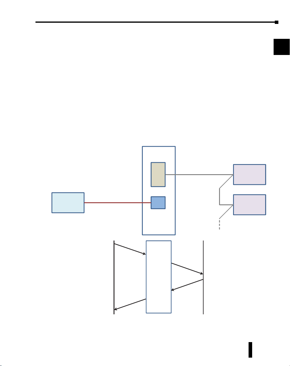
The Modbus TCP side of the Gateway functions as a TCP Server (slave) while the Modbus
RTU side functions as a serial Client (master). The serial side physical interface is
RS-422/485 2 or 4 wire so up to 128 Modbus RTU devices can be accessed by a Modbus
TCP Client device (up to 12 simultaneous connections). The actual number of Modbus
RTU slaves will depend on their individual transceiver loads.
Gateway Modbus
Address = 255
Serial
RS-485
Modbus
TCP Client
device
Ethernet
Modbus
RTU slave
device 1
Modbus
RTU slave
device 5
1
2
3
4
5
6
7
8
9
10
11
Other
Modbus Query
Client
The MB-GATEWAY User Manual describes the installation, configuration, and methods of
operation of the MB-GATEWAY Module.
MB-GATEWAY-USER-M Hardware User Manual, 1st Ed. Rev. H 02/21
MB-GATEWAY
Server
Modbus Query
Modbus Response
Master
Slave
1-2
12
13
14
A
B
C
D
Page 11

Chapter 1: Getting Started
Who Should Read This Manual
This manual contains important information for those who will install, maintain, and/or
operate The MB-GATEWAY Module.
1
Technical Support
We strive to make our manuals the best in the industry. We rely on your feedback to let us
know if we are reaching our goal. If you cannot find the solution to your particular application,
or, if for any reason you need technical assistance, please call us at:
770–844–4200
Our technical support group will work with you to answer your questions. They are available
Monday through Friday from 9:00 A.M. to 6:00 P.M. Eastern Time. We also encourage you
to visit our web site where you can find technical and non-technical information about our
products and our company.
http://www.automationdirect.com
2
3
4
5
6
7
8
9
10
11
12
MB-GATEWAY-USER-M Hardware User Manual, 1st Ed. Rev. H 02/21
13
14
A
B
C
D
1-3
Page 12

Conventions Used
Chapter 1: Getting Started
1
When you see the “notepad” icon in the left-hand margin, the paragraph to its immediate right will be a special
note. The word NOTE: in boldface will mark the beginning of the text.
When you see the “exclamation mark” icon in the left-hand margin, the paragraph to its immediate
right will be a warning. This information could prevent injury, loss of property, or even death (in
extreme cases). The word WARNING: in boldface will mark the beginning of the text.
Key Topics for Each Chapter
The beginning of each chapter will list the key topics that can be found in that chapter.
Getting Started
CHAPTER
1
In This Chapter...
General Information
.................................................................1-2
...........................................................................1-4Specifications
2
3
4
5
6
7
8
9
10
11
12
MB-GATEWAY-USER-M Hardware User Manual, 1st Ed. Rev. H 02/21
13
14
A
B
C
D
1-4
Page 13
Product Overview
Chapter 1: Getting Started
1
2
3
4
5
6
7
8
AutomationDirect’s MB-GATEWAY is a single port Modbus Gateway module that converts
Modbus TCP to Modbus RTU. It supports up to 12 simultaneous Modbus TCP Client
(master) Ethernet connections, and up to 128 RTU Server (slave) Serial connections.
MB-GATEWAY requires 10VDC to 36VDC from an external power supply. Each module
has one RJ45 10/100 Mbps Ethernet port and one RS-422/485 2 or 4 wire Serial Port. It
supports NetEdit (Ver 3.8 and later) or Web Browser based configuration tools.
Key features include:
• Automatic Read Function
• RJ45 10/100 Mbps Ethernet Port
• RS-422/485 2 or 4 wire Serial Port
• True failsafe receiver while maintaining EIA/TIA-485 compatibility
• Supports NetEdit and Web Browser configuration tools
• Autodetects Ethernet cable types (MDI/MDX)
• 35mm DIN rail mount
MB-GATEWAY-USER-M Hardware User Manual, 1st Ed. Rev. H 02/21
1-5
9
10
11
12
13
14
A
B
C
D
Page 14

What’s in the Box
Chapter 1: Getting Started
1
2
MB-GATEWAY
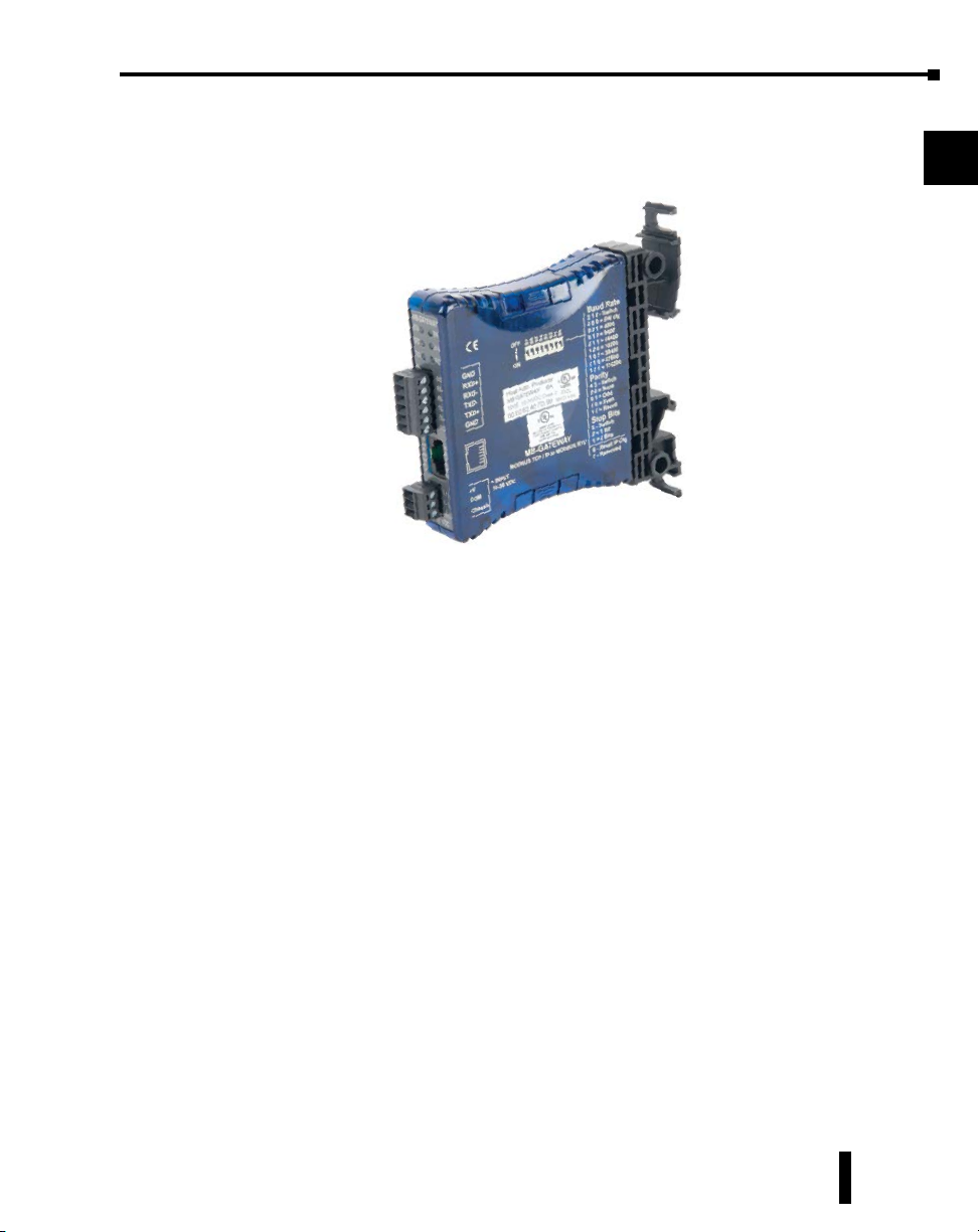
Mounting / Clearance Information
There are two options for mounting the MB-GATEWAY module.
Direct Mounting
The MB-GATEWAY module can be mounted in either a low-profile orientation or a slimmount orientation using screw holes on the provided mounting adapter. Screws are not
provided
DIN Rail Mounting
Adapter
Baud Rate
2 1 0 - Switch
0 0 0 = SW cfg
0 0 1 = 4800
0 1 0 = 9600
0 1 1 = 14400
1 0 0 = 19200
1 0 1 = 38400
1 1 0 = 57600
1 1 1 = 115200
Parity
4 3 - Switch
0 0 = None
0 1 = Odd
1 0 = Even
1 1 = Resvd
Stop Bits
5 - Switch
0 = 1 Bit
1 = 2 Bits
6 - Reset IP Cfg
7 - Reserved
3
4
5
6
7
8
9
10
11
12
13
14
A
B
MB-GATEWAY-USER-M Hardware User Manual, 1st Ed. Rev. H 02/21
C
D
1-6
Page 15
Chapter 1: Getting Started
C
US
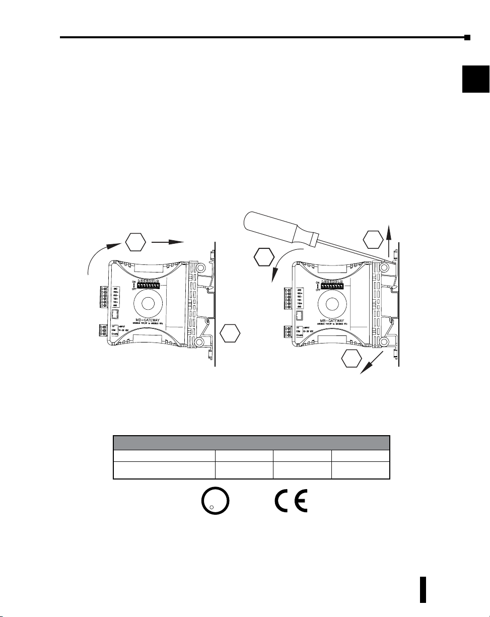
DIN Rail Mounting
The MB-GATEWAY module can be snapped onto a standard 35 mm x 7.5 mm height DIN
rail (Standard: CENELEC EN50022). They can be mounted either vertically or horizontally.
Refer to the mechanical drawings that follow for proper mounting.
DIN rail mounting steps:
1. Hook bottom back of unit over the DIN rail.
2. Push top back onto the DIN rail until it snaps into place.
DIN rail removal steps:
A. Pull up on tab at the top of the mounting adapter with a screwdriver.
B. Rotate the bottom of the unit away from the DIN rail.
C. Pull unit down and away from DIN rail.
1
2
3
4
5
Mounting
2
Agency Approvals
Name UL/CUL UL508 CE
MB-GATEWAY E185989 E185989 Yes
B
Baud Rate
2 1 0 - Switch
0 0 0 = SW cfg
0 0 1 = 4800
0 1 0 = 9600
0 1 1 = 14400
1 0 0 = 19200
1 0 1 = 38400
1 1 0 = 57600
1 1 1 = 115200
Parity
4 3 - Switch
0 0 = None
0 1 = Odd
1 0 = Even
1 1 = Resvd
Stop Bits
5 - Switch
0 = 1 Bit
1 = 2 Bits
6 - Reset IP Cfg
7 - Reserved
UL/CUL/CE Certification Numbers
U
R
1
L
Removal
Baud Rate
2 1 0 - Switch
0 0 0 = SW cfg
0 0 1 = 4800
0 1 0 = 9600
0 1 1 = 14400
1 0 0 = 19200
1 0 1 = 38400
1 1 0 = 57600
1 1 1 = 115200
Parity
4 3 - Switch
0 0 = None
0 1 = Odd
1 0 = Even
1 1 = Resvd
Stop Bits
5 - Switch
0 = 1 Bit
1 = 2 Bits
6 - Reset IP Cfg
7 - Reserved
C
A
6
7
8
9
10
11
12
13
14
A
B
C
MB-GATEWAY-USER-M Hardware User Manual, 1st Ed. Rev. H 02/21
D
1-7
Page 16

Chapter
Chapter
Chapter
speCifiCaTions
2
2
2
In this Chapter...
Specifications .................................................................................................................2-2
LED Indicators ................................................................................................................2-3
Dip Switch Information .................................................................................................2-4
Dimensional Drawing ....................................................................................................2-5
Page 17

Specifications
Chapter 2: Specifications
Port RJ-45
Speed 10/100 Mbps
Ethernet
Interface
Serial
Interface
Power Consumption
Wire Range
Wire Strip Length
Screw Torque
Operating Temperature Range
Storage Temperature Range
Humidity
Environmental Air
Vibration
Weight
Protection Built-in 1.5 KV magnetic isolation
Protocol Supported Modbus TCP/IP Server (Slave)
Clients (Masters)
Supported
Cable Type Autodetects Ethernet cable types (MDI/MDX)
Port 6-position terminal strip (Phoenix #1863194) provided
Supported Signal Lines
Supported Baud Rates
Parity Odd, Even, None
Data Bits 8
Stop Bits 1, 2
Protocol Supported Modbus RTU Client (Master)
Servers (Slaves)
Supported
Termination
Shock
Specifications
12 simultaneous Modbus TCP connections
RS-422 (5-wire) Signals: TX+, TX-, RX-, RX+, GND
RS-485 (3-wire) Signals: Data+, Data -, GND
300*, 600*, 1200*, 2400, 4800, 9600,
14.4k, 19.2k, 38.4k, 57.6k, 115.2k
* Cannot be set with DIP switches.
Must be set via web browser configuration.
128
Permanently installed 120ΩΩ resistor between
3-position terminal strip (Phoenix #1863165) provided
16 - 28 AWG Solid or Stranded Conductor (1.5 mm
For use in Pollution Degree 2 Environment. No corrosive gases
Data+ and Data -
Use Class 2 power supply
Use conductors rated 60/75 °C
0.24 - 0.27 in (6 - 7 mm)
0 to 60 °C (32 to 140 °F)
-20 to 70 °C (-4 to 158 °F)
5 to 95% RH (non-condensing)
2W
1.7 lb-in (0.2 Nm)
MIL STD 810C 514.2
MIL STD 810C 516.2
0.2 lbs (0.09 kg)
2
)
1
2
3
4
5
6
7
8
9
10
11
12
13
14
A
B
C
MB-GATEWAY-USER-M Hardware User Manual, 1st Ed. Rev. H 02/21
D
2-2
Page 18
LED Indicators
Chapter 2: Specifications
1
2
3
4
5
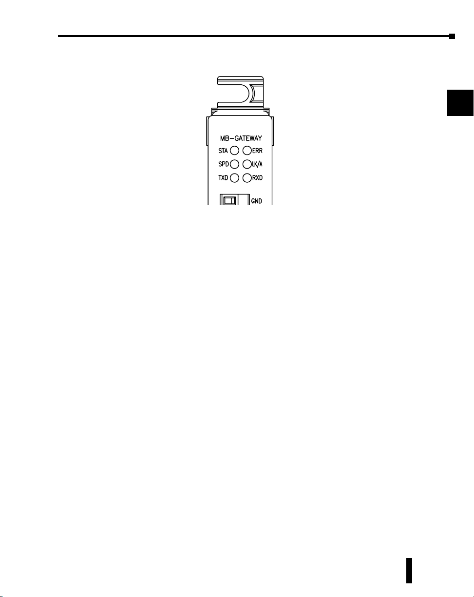
STA
The STA or STATUS LED is steady ON when the MB-GATEWAY has passed power-up
diagnostics and is ready for use.
SPD
The SPD or SPEED LED is used to represent the Ethernet speed. The LED will be ON
when the Ethernet speed is 100Mbps and OFF when the speed is 10Mbps.
TXD
The TXD or TRANSMIT DATA LED flashes to indicate that the MB-GATEWAY is
sending data through the serial port.
ERR
If the MB-GATEWAY’s ERR (ERROR) indicator is:
• ON - a critical error has occurred. The error may be in the card itself, or the result of a network
problem. The ERROR indication can be caused by a faulty ground, an electrical spike or other
types of electrical disturbances. Cycle power to the system to attempt clearing the error.
• Flashing once per second - a firmware update is in progress.
• Flashing randomly - a Modbus/RTU error. This could be a timeout or an actual error response.
Check the Gateway Device Status page on the MB-GATEWAY configuration web page to see the
quantity of Request Errors and the description of the Last Request Error.
A CRC error for an Automatic Reads table entry will flash the ERRor LED and set the Last
Request Error to: MODBUS_ERROR_MEMORY_PARITY_ERROR.
For a direct request from a Modbus TCP server, a Modbus RTU parity error will return the
error MODBUS_ERROR_MEMORY_PARITY_ERROR to the Modbus TCP server.
6
7
8
9
10
11
12
13
14
A
B
MB-GATEWAY-USER-M Hardware User Manual, 1st Ed. Rev. H 02/21
C
D
2-3
Page 19

Chapter 2: Specifications
LK/A
The LK/A or LINK GOOD/ACTIVITY LED flashes to indicate that the card sees data
traveling on the Ethernet network. If any network device is sending or receiving data, the
LK/A LED will be flashing. During heavy communication loads, this indicator will be steady
ON. If the LED is OFF, then a problem with the Ethernet connection has been detected.
RXD
The RXD or RECEIVE DATA LED flashes to indicate that the MB-GATEWAY is receiving
data through the serial port.
1
2
3
4
5
6
7
8
9
MB-GATEWAY-USER-M Hardware User Manual, 1st Ed. Rev. H 02/21
10
11
12
13
14
A
B
C
D
2-4
Page 20
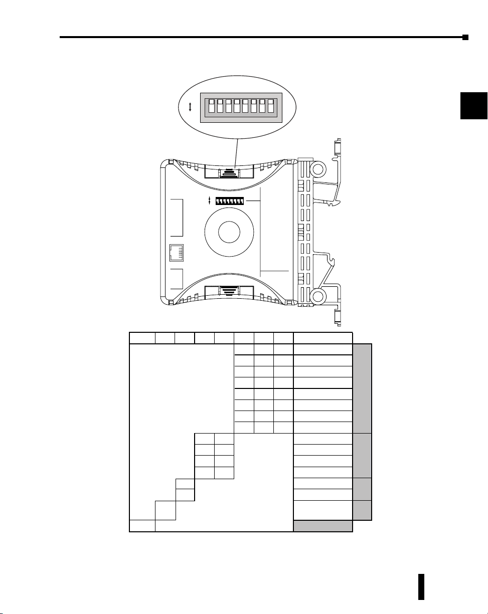
Dip Switch Information
01
12
and gateway address in the MB-GATEWAY to 0.0.0.0
Chapter 2: Specifications
S7S6S5S4S3S2S1
OFF
ON
OFF
S6S5S4S3S2S1S0
GND
RXD+
RXDTXDTXD+
GND
+V
+ INPUT
10-36 VDC
COM
Chasis
S7 S6 S5 S4 S3 S2 S1 S0 Switch seng
1
Rese rved
* Seng S6 to on will, on power cycle, set the IP address, subnet mask
S7
ON
MB-GATEWAY
MODBUS TCP/IP to MODBUS RTU
000Soware Config
001 4800
010 9600
011 14400
100 19200
101 38400
110 57600
111 115200
00 None
01 Odd
10 Even
11 Reserved
S0
Baud Rate
2 1 0 - Switch
0 0 0 = SW cfg
0 0 1 = 4800
0 1 0 = 9600
0 1 1 = 14400
1 0 0 = 19200
1 0 1 = 38400
1 1 0 = 57600
1 1 1 = 115200
Parity
4 3 - Switch
0 0 = None
0 1 = Odd
1 0 = Even
1 1 = Resvd
Stop Bits
5 - Switch
0 = 1 Bit
1 = 2 Bits
6 - Reset IP Cfg
7 - Reserved
Bit
Bits
*
S7 reserved
Baud Rate Parity
Bits
IP
1
2
3
4
5
6
7
8
9
10
11
12
13
14
A
Stop
B
Reset
C
D
MB-GATEWAY-USER-M Hardware User Manual, 1st Ed. Rev. H 02/21
2-5
Page 21
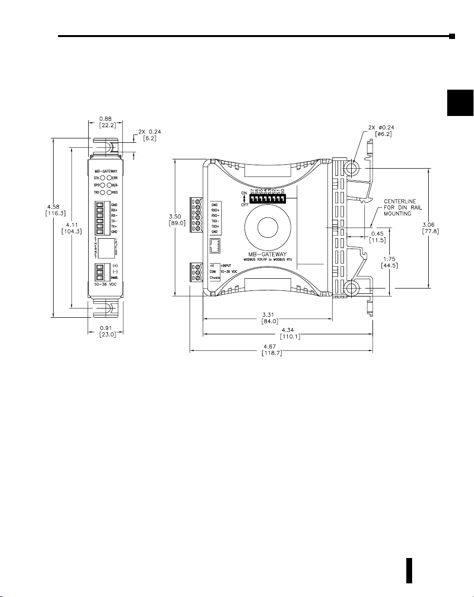
Dimensional Drawing
Chapter 2: Specifications
Inches [mm]
Baud Rate
2 1 0 - Switch
0 0 0 = SW cfg
0 0 1 = 4800
0 1 0 = 9600
0 1 1 = 14400
1 0 0 = 19200
1 0 1 = 38400
1 1 0 = 57600
1 1 1 = 115200
Parity
4 3 - Switch
0 0 = None
0 1 = Odd
1 0 = Even
1 1 = Resvd
Stop Bits
5 - Switch
0 = 1 Bit
1 = 2 Bits
6 - Reset IP Cfg
7 - Reserved
1
2
3
4
5
6
7
8
9
10
11
MB-GATEWAY-USER-M Hardware User Manual, 1st Ed. Rev. H 02/21
12
13
14
A
B
C
D
2-6
Page 22

Chapter
Chapter
Chapter
insTallaTion, WirinG
and ConfiGuraTion
3
3
2
In this Chapter...
Safety Guidelines ...........................................................................................................3-2
Plan for Safety ��������������������������������������������������������������������������������������������������������������3-2
Security Considerations ������������������������������������������������������������������������������������������������3-2
Wiring Diagrams ............................................................................................................3-3
MB-GATEWAY Configuration ........................................................................................3-4
NetEdit Configuration ��������������������������������������������������������������������������������������������������3-5
Function Codes Supported �������������������������������������������������������������������������������������������3-6
Log Modbus/TCP and/or RTU requests to SMTPViewer ������������������������������������������������3-6
Page 23

Safety Guidelines
Chapter 3: Installation, Wiring and Configuration
Warning: Providing a safe operating environment for personnel and equipment is your responsibility
and should be your primary goal during system planning and installation. Automation systems can
fail and may result in situations that can cause serious injury to personnel or damage to equipment.
Do not rely on the automation system alone to provide a safe operating environment. You should use
external electromechanical devices, such as relays or limit switches, that are independent of the PLC
application to provide protection for any part of the system that may cause personal injury or damage.
Every automation application is different, so there may be special requirements for your particular
application. Make sure you follow all national, state, and local government requirements for the proper
installation and use of your equipment.
Plan for Safety
The best way to provide a safe operating environment is to make personnel and equipment
safety part of the planning process. You should examine every aspect of the system to
determine which areas are critical to operator or machine safety. If you are not familiar with
control system installation practices, or your company does not have established installation
guidelines, you should obtain additional information from the following sources.
• NEMA — The National Electrical Manufacturers Association, located in Washington, D.C.
publishes many different documents that discuss standards for industrial control systems. You can
order these publications directly from NEMA. Some of these include:
ICS 1, General Standards for Industrial Control and Systems
ICS 3, Industrial Systems
ICS 6, Enclosures for Industrial Control Systems
• NEC — The National Electrical Code provides regulations concerning the installation and use of
various types of electrical equipment. Copies of the NEC Handbook can often be obtained from
your local electrical equipment distributor or your local library.
• Local and State Agencies — many local governments and state governments have additional
requirements above and beyond those described in the NEC Handbook. Check with your local
Electrical Inspector or Fire Marshall office for information.
Security Considerations
When implementing any method of remote access to your equipment, you need to consider
the security exposure in order to minimize the risks to your processes and your equipment.
Security should always be carefully evaluated for each installation. Refer to “Appendix C:
Security Considerations for Control Systems Networks” for more information.
1
2
3
4
5
6
7
8
9
10
11
12
13
14
A
MB-GATEWAY-USER-M Hardware User Manual, 1st Ed. Rev. H 02/21
B
C
D
3-2
Page 24
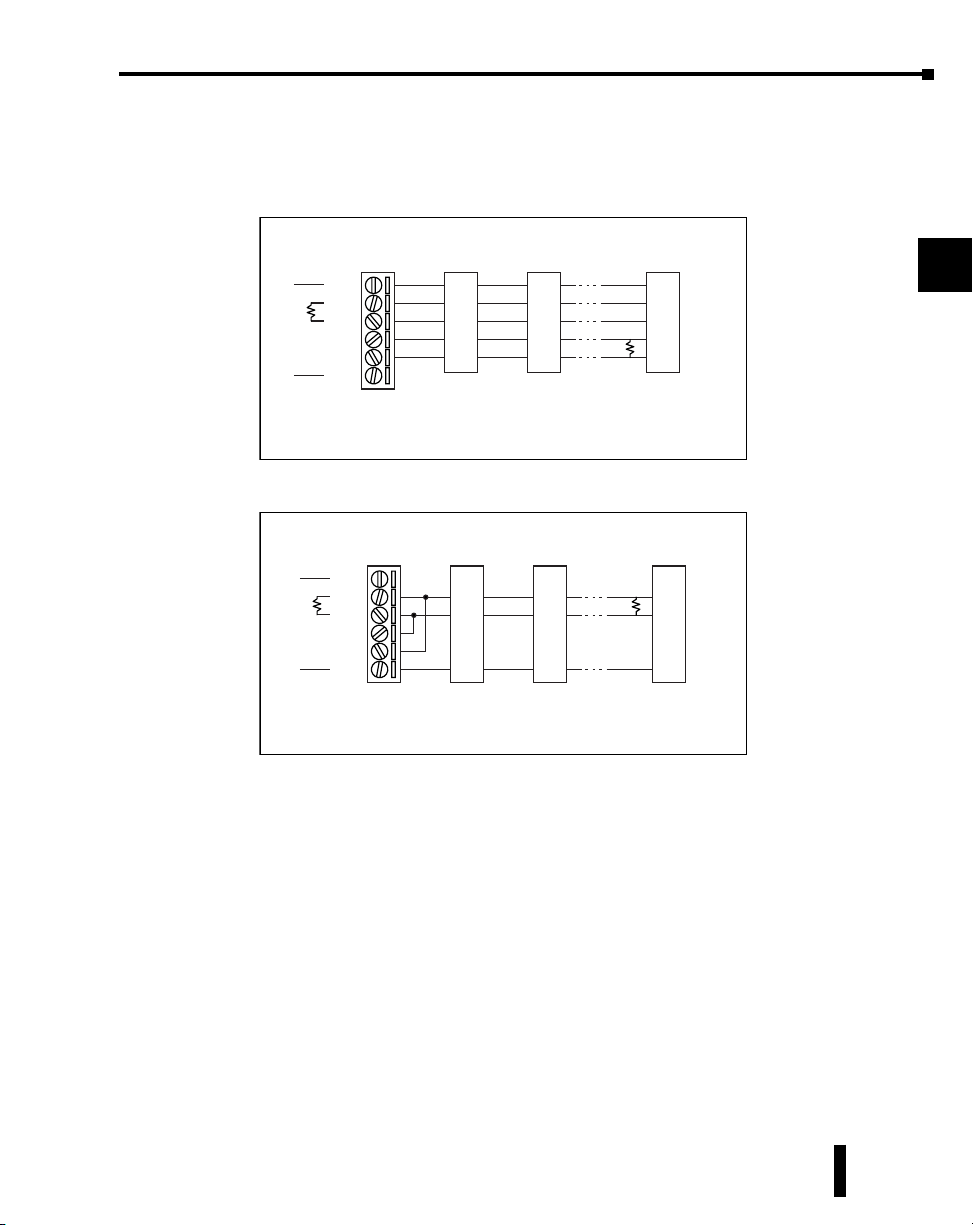
Wiring Diagrams
The MB-GATEWAY module can be wired in either 4-wire or 2-wire mode.
Chapter 3: Installation, Wiring and Configuration
1
Gateway Slave 1Slave 2Last Slave
GND
RX+
RXTXTX+
Internally Connected
GND
(Gateway contains a
120Ω Termination Resistor
between RX+ and RX-)
Recommended Cable - AutomationDirect L19773 shielded cable or equivalent
GND
TX+
TX-
RX-
RX+
GND
TX+
TXRXRX+
GND
TX+
TX-
RX-
*
RX+
* User Supplied
120Ω Termination
Resistor
RS-485
Gateway Slave 1Slave 2Last Slave
GND
RS-422/RS-485
RX+
RX-
TX-
TX+
Internally Connected
GND
(Gateway contains a
120Ω Termination Resistor
between RX+ and RX-)
Recommended Cable - AutomationDirect L19954 shielded cable or equivalent
D+
D-
GND
D+
D-
GND
D+
*
D-
GND
* User Supplied
120Ω Termination
Resistor
2
3
4
5
6
7
8
9
10
11
12
MB-GATEWAY-USER-M Hardware User Manual, 1st Ed. Rev. H 02/21
13
14
A
B
C
D
3-3
Page 25

MB-GATEWAY Configuration
The MB-GATEWAY supports 128 Modbus RTU nodes on the serial side. The RS-485
specification supports up to 32 devices before a repeater device is required. Proper cabling and
termination is required. For RS-485 4-wire installations , a cable with the proper shielding
and impedance should be used such as a Belden model 9843. For RS-485 2 wire installations,
a cable such as the Belden model 9842 should be used. A 120 ohm resistor should be used
for termination on each end of the network as shown in the previous wiring diagrams. The
GATEWAY module has a termination resistor pre-installed so only one resistor needs to be
added to the opposite end of the network away from the Gateway module.
The MB-GATEWAY module supports up to 12 simultaneous Modbus TCP connections.
The MB-GATEWAY’s TCP listening port is the standard Modbus TCP port 502 (not
configurable).
One of the major features of the MB-GATEWAY module is the “Automatic Read” function.
This feature utilizes the ‘idle’ time of the module while it is waiting for Ethernet requests.
The Automatic Read function can be configured to poll specific Modbus data points of the
serial nodes and place that data into a local ‘data buffer’. If a Modbus Ethernet request comes
in for one of those data points, the MB-GATEWAY module will immediately respond with
the data from local buffer and thereby respond much faster than it would if it had to generate
a new serial request. See Chapter 5 for more information.
The factory IP setting of the MB-GATEWAY module is to retrieve an IP address via
DHCP. In order to see what IP address has been assigned and/or to change that setting the
NetEdit software tool will be required to discover and configure the MB-GATEWAY TCP/
IP settings. NetEdit is a free tool that is accessible at AutomationDirect’s website or HOST
engineering’s website (http://www.hosteng.com/SW-Products/SP_Demo_Utilites.htm#NetEdit3).
Chapter 3: Installation, Wiring and Configuration
1
2
3
4
5
6
7
8
9
10
NOTE: NetEdit version 3.8 or later is required to support MB-GATEWAY
MB-GATEWAY Configuration continued on the next page
MB-GATEWAY-USER-M Hardware User Manual, 1st Ed. Rev. H 02/21
11
12
13
14
A
B
C
D
3-4
Page 26
Chapter 3: Installation, Wiring and Configuration
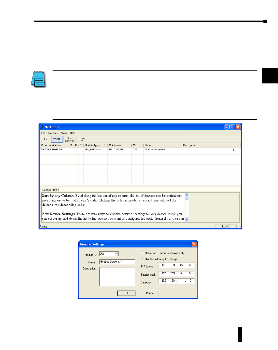
NetEdit Configuration
Using NetEdit is very simple. Once the software has been installed, follow the steps below to
configure the settings of your MB-GATEWAY module.
• Start the software. It will scan automatically when you start it but if your MB-GATEWAY is
inaccessible at the point of starting the software, you can press the “Scan Network” button at the
top to make it scan again once the MB-GATEWAY has become accessible.
1
2
NOTE: If you are unable to see the MB-GATEWAY...
1) If your PC has more than one NIC (Network Interface Card), e.g. a wireless and a wired, then
you may need to either disable the NIC(s) you are not using, or re-prioritize them such that the
NIC you are using is top priority.
2) Verify the Network Interface on your PC is functioning properly
3) Verify all connections between the PC and the MB-GATEWAY are properly made
4) Disable your firewall or open TCP port 28787 to allow NetEdit.
5) NetEdit version 3.8 or later is required to support MB-GATEWAY.
• In the Main window, double click on the MB-GATEWAY module that you want to configure.
3
4
5
6
7
8
9
10
11
12
13
• Select “Use the following IP settings”.
• Type in the settings that are compatible with your network and press the OK button and the
MB-GATEWAY module’s IP settings are now configured.
MB-GATEWAY-USER-M Hardware User Manual, 1st Ed. Rev. H 02/21
14
A
B
C
D
3-5
Page 27

Chapter 3: Installation, Wiring and Configuration
After the MB-GATEWAY module’s IP settings have been configured to be compatible
with the subnet of your PC, you can open Internet Explorer (or the Web browser of your
choice) and continue the configuration for your application. You can also right click on the
MB-GATEWAY in the main NetEdit window and choose “Start Web based config…” to
start your default Web browser with the correct IP address pre-configured for you.
Function Codes Supported
The function codes supported by the MB-GATEWAY differ based upon whether the target
from the Modbus Client is the MB-GATEWAY directly by utilizing the Gateway Modbus
ID and the Automatic Read function or direct access to a Modbus serial slave by specifying
the Unit ID of the Modbus Slave node itself.
1
2
3
4
Target = MB-GATEWAY Module (using Gateway Modbus ID and Automatic Read
Function):
• Function Code 1 (Read Coils 0xxxxx)
• Function Code 2 (Read Input Bits 1xxxxx)
• Function Code 3 (Read Holding Registers 4xxxxx)
• Function Code 4 (Read Input Registers 3xxxxx)
• Function Code 8 (Read Diagnostics <Read Query Data Function>)
Target = MB-GATEWAY Modbus Slave Node (using Unit ID of Slave Node):
• Any function code supported by the Modbus Slave device
Log Modbus/TCP and/or RTU requests to SMTPViewer
Available in firmware 1.0.679 and later
Using the SMTPViewer (download from HostEng.com and install it in the \HAPTools
folder), you can see the TCP and RTU requests that are being processed by the
MB-GATEWAY. This logging feature will only send packets to the PC that requested the
logging; therefore it is not using broadcast packets, and each Gateway can only log data to 1
PC at a time.
To use logging, connect to MB_GATEWAY with SMTPViewer (UDP only; port
0x7272) and issue the following command:
‘Log [req] [rsp] [rtu] [tcp] [dev #] [raw]’
req = Log requestsrsp = Log responsesrtu = Log RTU transactionstcp = Log TCP
transactionsraw = Show raw bytes instead of decoding transactionsdev # = Ex ‘dev 1’ would
show only transactions for device 1
For example, to see all Modbus/RTU transactions (requests and responses) to/from device 1
in a decoded form, the command is:‘Log rtu req rsp dev 1’
The command ‘log’ by itself defaults to ‘log req rsp rtu tcp’ which will show all requests and
responses for all devices in a decoded form. All forms of the log command toggle from on to
off, so you can issue the same command again to turn logging off.
5
6
7
8
9
10
11
12
13
14
A
B
C
D
MB-GATEWAY-USER-M Hardware User Manual, 1st Ed. Rev. H 02/21
3-6
Page 28

Chapter
Chapter
Chapter
parameTers
4
4
4
In this Chapter...
Home Page ...................................................................................................................4-2
Gateway Modbus ID ..................................................................................................... 4-3
Module Name and Module Description ......................................................................4-4
IP Setup Configuration Page ........................................................................................4-5
Serial Port Configuration Page ....................................................................................4-6
Set Up Slave Timeout / Retries Page ........................................................................... 4-7
Gateway Device Status Page ........................................................................................ 4-8
1 Automatic Reads ����������������������������������������������������������������������������������������������������� 4-9
2 Last Modbus TCP Request ��������������������������������������������������������������������������������������4-9
3 Last Modbus RTU Request ������������������������������������������������������������������������������������4-10
4 Status Information ������������������������������������������������������������������������������������������������ 4-10
Setup Automatic Read Page ��������������������������������������������������������������������������������������4-10
Firmware Updates ......................................................................................................4-11
Page 29
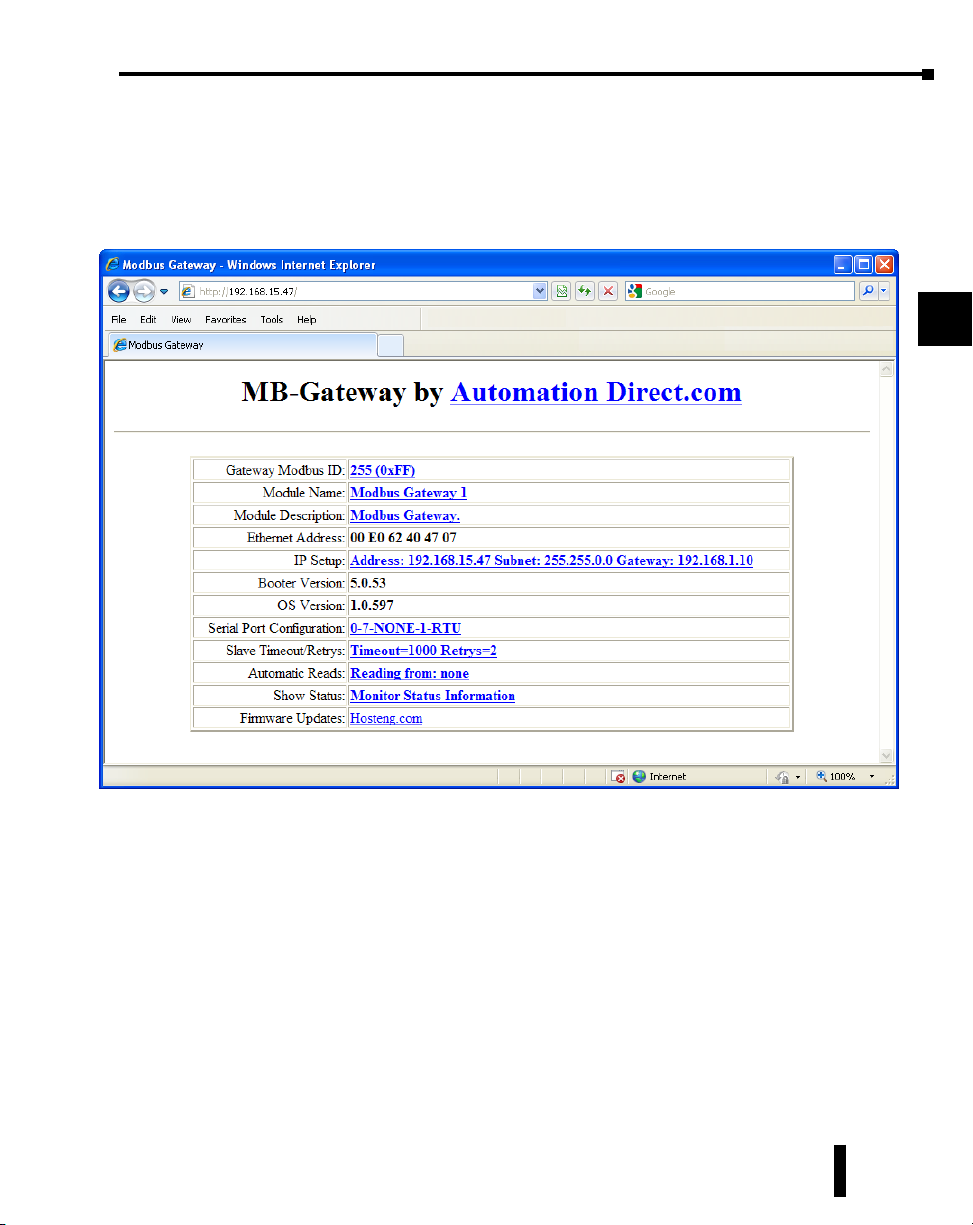
Home Page
The configuration of the MB-GATEWAY is accessed through a web browser at the wellknown HTTP port 80 (not configurable). The image below shows the home page that will
be displayed when the web server of the MB-GATEWAY module is accessed. From this
page, all of the different setup screens can be accessed.
Chapter 4: Parameters
1
2
3
4
5
6
7
8
9
MB-GATEWAY-USER-M Hardware User Manual, 1st Ed. Rev. H 02/21
10
11
12
13
14
A
B
C
D
4-2
Page 30

Gateway Modbus ID
The Gateway Modbus ID is used with the Automatic Read function. This is how the local
data buffer is accessed by the Modbus Client device. The usage of this field will be explained
in more detail in the Automatic Read Function section.
The Modbus ID used in this field should be unique to the serial network and not assigned to any real Modbus RTU
device.
Chapter 4: Parameters
1
2
3
4
5
6
7
8
9
The Back, Send and Reset buttons that appear on these pages have the following behavior:
The Back button will browse back to the previous page viewed without saving any changes
made on the current page.
The Send button will Send any changes made on this page to the MB-GATEWAY,
effectively saving those changes.
The Reset button will undo any changes made on this page, back to the values that have been
Sent to the MB-GATEWAY previously.
MB-GATEWAY-USER-M Hardware User Manual, 1st Ed. Rev. H 02/21
4-3
10
11
12
13
14
A
B
C
D
Page 31

Module Name and Module Description
These fields are used only for reference and identification when managing several different
MB-GATEWAY modules on a network.
Chapter 4: Parameters
1
2
3
4
5
6
7
8
9
MB-GATEWAY-USER-M Hardware User Manual, 1st Ed. Rev. H 02/21
10
11
12
13
14
A
B
C
D
4-4
Page 32

IP Setup Configuration Page
The IP address, Subnet Mask and Default Gateway address can be configured on this page.
Chapter 4: Parameters
1
You may lose communications with the MB-GATEWAY module if you configure an IP address and/or
Subnet Mask that is not compatible with the subnet of your PC’s Network Interface Card. You may be
required to change the subnet settings of your PC or use the NetEdit tool to regain communications in
this situation.
2
3
4
5
6
7
8
9
10
11
12
MB-GATEWAY-USER-M Hardware User Manual, 1st Ed. Rev. H 02/21
13
14
A
B
C
D
4-5
Page 33

Serial Port Configuration Page
This page is used to configure the serial port parameters if you do not want to use the
dipswitch settings or if baud rates different than the dipswitch settings range are desired. The
serial port settings should match the settings of the Modbus RTU serial nodes connected to
the MB-GATEWAY module. In some situations, such as a high amount of electrical noise,
poor cabling, etc., it may be necessary to reduce the baud rate on the MB-GATEWAY
module AND serial devices on the network.
Chapter 4: Parameters
1
2
3
In order to use the software based configuration, switches S0, S1, and S2 must be turned OFF.
4
5
6
7
8
9
10
11
12
13
14
MB-GATEWAY-USER-M Hardware User Manual, 1st Ed. Rev. H 02/21
A
B
C
D
4-6
Page 34

Set Up Slave Timeout / Retries Page
The “Set Up Slave Timeout/Retries” page is used to configure the timing on the serial side of
the MB-GATEWAY module. By default, all serial requests will use the “Default Timeout”
value and “Default Retries” value. If there are devices on the serial network that require
different timing adjustments, those exception cases can be added to the table below. Simply
specify the node ID, the timing value and retry count necessary for that device.
The way that the timeout and retry field is utilized is:
The MB-GATEWAY will send a request to the serial device, if there is no reply from the
device within the Timeout value specified, the MB-GATEWAY will send another request
and wait again. It will do this for the number of times specified in the Retry field. Once the
MB-GATEWAY has attempted to access the device for the number of retry counts specified
and no reply is forthcoming, the MB-GATEWAY will respond with an exception error: 04
(Slave device failure).
The “Inter-packet TX Delay” field specifies how long between serial requests the
MB-GATEWAY module should wait . This applies to all serial requests to all serial devices
on the serial side of the module.
Chapter 4: Parameters
1
2
3
4
5
6
7
8
9
MB-GATEWAY-USER-M Hardware User Manual, 1st Ed. Rev. H 02/21
10
11
12
13
14
A
B
C
D
4-7
Page 35

Gateway Device Status Page
The Gateway Device Status page contains statistical information about the MB-GATEWAY
module that can be used to gauge the performance of the communications and to
troubleshoot communications.
Chapter 4: Parameters
1
2
3
4
5
6
7
8
9
MB-GATEWAY-USER-M Hardware User Manual, 1st Ed. Rev. H 02/21
10
11
12
13
14
A
B
C
D
4-8
Page 36

Chapter 4: Parameters
1 Automatic Reads
This table shows statistical information about the requests being sent when the Automatic
Read function is being utilized. This information can help to indicate whether this table has
been configured correctly or not.
Table Item: Corresponds to the position in the table of the “Set Up Automatic Reads” page.
Error Count: Indicates how many error requests have occurred for that table item. This could be a
timeout error or an exception response.
Last Error: Indicates the error code from the last error request. If the device fails to respond
(Timeout), the error “Slave Device Failure” will be shown in this field.
Retries: Indicates how many retries have occurred. It is a cumulative value and does not reset unless
the module has been power cycled or the “Clear Values” button at the bottom has been
pressed.
Timeout: Indicates how many times a request has not received a reply within the specified timeout
period. It is a cumulative value and does not reset unless the module has been power
cycled or the “Clear Values” button at the bottom has been pressed.
Number Completed: Indicates how many requests have been sent for that table item.
2 Last Modbus TCP Request
This table shows statistical information about the last request that was received on the
Modbus TCP side from a Modbus TCP Client device.
Slave Number: Indicates the “Unit ID” number within the Modbus TCP header of the Modbus
TCP request.
Function: Indicates the Modbus function requested within the Modbus TCP request.
Reference: Indicates the starting address requested within the Modbus TCP request. The
“Reference” value is the offset from 0. More information will be explained in the
Automatic Read Function section as to how this Reference value corresponds to a
Modicon style address that is found in many Modbus devices.
Count: Indicates the number of Registers, Coils or Bits requested within the Modbus TCP request.
Data: This field indicates the Data values written to the MB-GATEWAY module when a Write
function has been sent from the Modbus TCP Client device.
Status: Indicates the action taken by the MB-GATEWAY module upon receiving the Modbus TCP
Client request.
Found in cache = If the Modbus TCP Client request is targeted to the MB-GATEWAY
Module’s Modbus ID and the request corresponds with an address mapped
in the Automatic Read Function, the MB-GATEWAY module will respond
with the data from its local cache. The MB-GATEWAY module will also
return the data from its local cache if the TCP Client request corresponds
with a node number and address that has been configured in the Automatic
Read function table.
Completed = If the request does not meet the criteria explained above, a serial request is created.
Return: This field will indicate whether an error has occurred or not. If this field displays “No
Error”, the request was successful. Otherwise, the Modbus error text will be shown. Refer
to the Modbus specifications error code lists for detailed explanations of each error code.
1
2
3
4
5
6
7
8
9
10
11
12
13
14
A
B
C
D
MB-GATEWAY-USER-M Hardware User Manual, 1st Ed. Rev. H 02/21
4-9
Page 37

Chapter 4: Parameters
3 Last Modbus RTU Request
This table shows the last Modbus RTU request formed by the MB-GATEWAY module
based upon the Modbus TCP Client request received on the Ethernet side.
Slave Number: This is the Node number that was targeted in the last Modbus RTU serial request.
Function: Indicates the Function Code sent to the Modbus serial device in the last request.
Reference: Indicates the starting address requested within the Modbus RTU request. The
“Reference” value is the offset from 0. More information will be explained in the
Automatic Read Function section as to how this Reference value corresponds to a
Modicon style address that is found in many Modbus devices.
Count: Indicates the number of Registers, Coils or Bits requested within the Modbus RTU request.
Data: This field indicates the Data values written to the Modbus RTU device when a Write function
has been sent.
Status: Indicates the action taken by the MB-GATEWAY module on the Modbus RTU side.
Waiting for Header = This indicates that the MB-GATEWAY module has sent a request and is
waiting for the Reply.
Timeout = If a request was sent to a Modbus RTU device and no reply is received, this message
will appear.
Completed = If the request was sent and a reply was received, this message will show in the
Status field.
Return: This field will indicate whether an error has occurred or not. If this field displays “No
Error”, the request was successful. Otherwise, the Modbus error text will be shown. Refer to
the Modbus specifications error code lists for detailed explanations of each error code.
4 Status Information
This table shows a summary of the current session (since power cycle or Clear Values button
selected). Comparing Requests to Cache Hits can help indicate whether the Automatic Reads
are configured to maximize efficient communications. And total Error, Retry and Timeout
data can indicate health of communications.
A CRC error for an Automatic Reads table entry will flash the ERRor LED and set the Last
Request Error to: MODBUS_ERROR_MEMORY_PARITY_ERROR.
For a direct request from a Modbus TCP server, a Modbus RTU parity error will return the
error MODBUS_ERROR_MEMORY_PARITY_ERROR to the Modbus TCP server.
Setup Automatic Read Page
The Automatic Read Feature is explained in detail in Chapter 5: Automatic Read Feature.
1
2
3
4
5
6
7
8
9
10
11
12
13
14
A
MB-GATEWAY-USER-M Hardware User Manual, 1st Ed. Rev. H 02/21
B
C
D
4-10
Page 38

Firmware Updates
This link sends you to Host Engineering’s website to retrieve the latest firmware for the
MB-GATEWAY module. The NetEdit tool is required to upgrade firmware in the
MB-GATEWAY module. The steps are shown below:
Open the NetEdit software. You may allow the NetEdit software to download the latest
firmware for the MB-GATEWAY module by clicking on File-> Live Update.
Once you have the firmware file to load into the MB-GATEWAY module, click on the Scan
Network button at the top left to browse for the MB-GATEWAY module that is in the
subnet of the PC.
Chapter 4: Parameters
1
2
3
4
5
6
7
8
9
Click on the GATEWAY module that you wish to upgrade and then select the “General
Settings” tab at the bottom of the screen. Click on the “Update Firmware” button in the
“General Settings” tab. You will get a dialog box to select the firmware file that you wish to
upgrade to. Select the correct file and click on the “Open” button.
Firmware Updates continued on the next page.
MB-GATEWAY-USER-M Hardware User Manual, 1st Ed. Rev. H 02/21
4-11
10
11
12
13
14
A
B
C
D
Page 39

Chapter 4: Parameters
1
2
Confirm that you wish to perform the upgrade by clicking on the “Yes” button.
Once the process is complete, you will receive a dialog confirming success.
3
4
5
6
7
8
9
10
11
12
13
MB-GATEWAY-USER-M Hardware User Manual, 1st Ed. Rev. H 02/21
14
A
B
C
D
4-12
Page 40

Chapter
Chapter
Chapter
auTomaTiC read
feaTure
5
5
5
In this Chapter...
Automatic Read Feature ............................................................................................... 5-2
Situation 1:������������������������������������������������������������������������������������������������������������������5-3
Situation 2:������������������������������������������������������������������������������������������������������������������5-6
Additional Optimization ............................................................................................... 5-8
Automatic Read Status Data ���������������������������������������������������������������������������������������� 5-9
Page 41

Automatic Read Feature
The Automatic Read Feature allows the MB-GATEWAY module to utilize some of the idle
time that usually occurs between Modbus TCP requests from the Client device. Note that
this feature only allows the reading of data from the serial devices and not writing to them.
Up to 16 automatic read requests can be configured.
Chapter 5: Automatic Read Feature
1
2
3
4
5
6
7
8
9
MB-GATEWAY-USER-M Hardware User Manual, 1st Ed. Rev. H 02/21
10
11
12
13
14
A
B
C
D
5-2
Page 42

Chapter 5: Automatic Read Feature
The MB-GATEWAY module can be assigned a Modbus Node address that corresponds with
the “Unit ID” number that is sent within the Modbus TCP header that is typically used to
target a Modbus RTU node that is on the serial side of the MB-GATEWAY. Therefore, the
Node number that is assigned to the MB-GATEWAY module should be unique from any
Modbus RTU nodes on the serial network. The Automatic Read function reads the specified
registers, bits or coils from the Modbus RTU nodes and places that data into the specified
MB-GATEWAY addresses that can be retrieved on the Ethernet side by specifying the
MB-GATEWAY’s Modbus address in the Unit ID field of the Modbus TCP client request.
An example is shown below:
1
2
3
Situation 1:
Modbus TCP Client device sends a request for a device not configured in the Automatic
Read table. This will, in turn, generate a fresh new request on the serial side of the
MB-GATEWAY module.
Memory
To Read
3- Holding
Regs.
Request:
Slave Num = 5,
Modbus
TCP Client
device
Step 1: Modbus TCP request is generated to Serial Slave Num 5 at Starting Address 10, size 1
Start Addr = 10,
Num of Elements = 1
Slave
Number
RTU
Number
Start
Address
Elements
1010
MB-GATEWAY
Gateway Modbus
Address = 255
Serial
RS-485
Ethernet
Gateway
of
Memory
Address
Other
devices
Modbus
RTU slave
device 1
Modbus
RTU slave
device 5
4
5
6
7
8
9
10
11
12
13
14
MB-GATEWAY-USER-M Hardware User Manual, 1st Ed. Rev. H 02/21
A
B
C
D
5-3
Page 43

Chapter 5: Automatic Read Feature
Modbus
TCP Client
device
Memory
To Read
3- Holding
Regs.
Slave
Number
RTU
Number
Start
Address
Elements
1010
MB-GATEWAY
Gateway Modbus
Address = 255
Serial
RS-485
Ethernet
of
Request:
Slave Num = 5,
Start Addr = 10,
Num of Elements = 1
Gateway
Memory
Address
RTU slave
RTU slave
Other
devices
Step 2: Request is then generated on the Serial side of the MB-GATEWAY.
Memory
To Read
3- Holding
Regs.
Slave
Number
RTU
Number
Start
Address
Elements
1010
Gateway
of
Memory
Address
1
2
3
Modbus
4
device 1
5
Modbus
6
device 5
7
8
9
10
Modbus
TCP Client
device
MB-GATEWAY
Gateway Modbus
Address = 255
Serial
RS-485
Modbus
RTU slave
device 1
Reply with data
Ethernet
Modbus
RTU slave
device 5
Other
devices
Step 3: Serial Node replies with data
MB-GATEWAY-USER-M Hardware User Manual, 1st Ed. Rev. H 02/21
11
12
13
14
A
B
C
D
5-4
Page 44

Chapter 5: Automatic Read Feature
Modbus
TCP Client
device
Memory
To Read
3- Holding
Regs.
Reply with data
Step 4: Gateway generates TCP reply and sends back to Client device.
Slave
Number
RTU
Number
Start
Address
Elements
1010
MB-GATEWAY
Gateway Modbus
Address = 255
Serial
RS-485
Ethernet
Gateway
of
Memory
Address
Other
devices
Modbus
RTU slave
device 1
Modbus
RTU slave
device 5
1
2
3
4
5
6
7
8
9
10
MB-GATEWAY-USER-M Hardware User Manual, 1st Ed. Rev. H 02/21
11
12
13
14
A
B
C
D
5-5
Page 45

Chapter 5: Automatic Read Feature
Situation 2:
In this example, the Modbus TCP Client device is sending a request directly to the
MB-GATEWAY itself that spans multiple entries in the Automatic Read table.
Memory
To Read
3- Holding
Regs.
3- Holding
Regs.
Modbus
TCP Client
device
Step 1: Before a request even comes in on the Ethernet side, the MB-GATEWAY is reading data from the
serial slaves at the “Inter-packet TX Delay” rate and placing that data into its local cache.
Slave
Number
RTU
Number
Start
Address
Elements
1010
5011
MB-GATEWAY
Gateway Modbus
Address = 255
Serial
RS-485
Ethernet
Cache:
Register 0
Register 1
data
Gateway
of
Request:
Slave Num = 1,
Start Addr = 0,
Num of Elements = 1
Request:
Slave Num = 5,
Start Addr = 0,
Num of Elements = 1
Memory
Address
Reply with data
Reply with data
Other
devices
Modbus
RTU slave
device 1
Modbus
RTU slave
device 5
1
2
3
4
5
6
7
8
9
10
11
MB-GATEWAY-USER-M Hardware User Manual, 1st Ed. Rev. H 02/21
12
13
14
A
B
C
D
5-6
Page 46

Chapter 5: Automatic Read Feature
Memory
To Read
3- Holding
Regs.
3- Holding
Regs.
Request:
Slave Num = 255,
Modbus
Start Addr = 0,
Num of Elements = 2
TCP Client
device
Step 2: Modbus TCP Request is generated to Serial Slave Num 255 at Starting Address 0, size 2.
Memory
To Read
3- Holding
Regs.
3- Holding
Regs.
Slave
Number
Slave
Number
RTU
Number
Start
Address
Elements
1010
5011
MB-GATEWAY
Gateway Modbus
Address = 255
Serial
RS-485
Ethernet
Cache:
Register 0
Register 1
data
RTU
Number
Start
Address
Elements
1010
5011
MB-GATEWAY
Gateway Modbus
Address = 255
Serial
RS-485
Gateway
of
Memory
Address
Gateway
of
Memory
Address
Other
devices
Modbus
RTU slave
device 1
Modbus
RTU slave
device 5
Modbus
RTU slave
device 1
Modbus
TCP Client
device
Step 3: MB-GATEWAY immediately generates TCP reply and sends back to Client device from local cache
without generating a new serial request.
Reply with data
Ethernet
Cache:
Register 0
Register 1
data
Other
devices
Modbus
RTU slave
device 5
The response time for the TCP request will be significantly faster when the request is targeted
at an address in the Automatic Read table. This can be advantageous if the Modbus TCP
Client is a device that is busy doing numerous other tasks, such as a PLC.
1
2
3
4
5
6
7
8
9
10
11
12
13
14
A
B
C
D
MB-GATEWAY-USER-M Hardware User Manual, 1st Ed. Rev. H 02/21
5-7
Page 47

Additional Optimization
An additional method of optimization is used in the MB-GATEWAY. If a request is sent to
the MB-GATEWAY from the Modbus TCP Client targeted at a Node number and starting
address that is equivalent to an entry in the Automatic Read table, the MB-GATEWAY will
treat the request as if it had been targeted at the MB-GATEWAY Modbus address and will
respond from its local data cache since the data is the same.
Shown below are some more detailed explanations of the different fields that can be
configured in the Automatic Read Function table.
Memory to Read:
There are 5 options:
0 – Unused Entry = Disables this entry in the table.
1 – Coils = Configures this entry to read “Modbus Coils” (Read/Write bits).
2 – Discrete Inputs = Configures this entry to read “Modbus Input Bits” (Read Only bits).
3 – Holding Regs = Configures this entry to read “Modbus Holding Registers” (Read/Write 16
4 – Input Regs = Configures this entry to read “Modbus Input Registers” (Read Only 16 bit
Slave Number:
The network address of the Modbus RTU device to be read on the serial network.
RTU Start Address:
The starting address (based at 0) to be read in the targeted Modbus RTU device on the serial
network.
Number of Elements:
The Number of elements to read from the targeted Modbus RTU device on the serial network.
If the Read is from Coils or Discrete Inputs, the number specified will be the number of bits
from 1 - 2000. If the Read is from Holding or Input Registers, the number specified will be the
number of words (16 bit) from 1 - 125.
Gateway Memory Address:
The starting address in the GATEWAY module’s local data cache to place the data that has been
read from the Modbus RTU device on the serial network.
Gateway Modbus Address:
Displays the Modbus address that the GATEWAY module has been configured for (done in the
“Gateway Modbus ID” section of the home page).
Auto Assign Gateway Addresses:
Selecting this option will allow the configuration software to automatically choose the best local
addresses to place the data that has been read from the Modbus RTU devices.
When the Auto Assign Gateway Addresses option is NOT selected, care must be taken so the
data from different Automatic Reads doesn’t overlap in the Gateway’s internal memory. If you
specify an Automatic Read that will create overlapping data, the value in the Gateway Memory
Address field for that Read will be red.
By default the Gateway will store the data from the individual automatic reads for the same
memory types in consecutive locations in the Gateway’s internal memory. Storing this data in
consecutive data locations in the Gateway’s internal memory allows reads to be optimized into
as few requests as possible.
bit registers).
registers).
Chapter 5: Automatic Read Feature
1
2
3
4
5
6
7
8
9
10
11
12
13
14
A
B
C
D
MB-GATEWAY-USER-M Hardware User Manual, 1st Ed. Rev. H 02/21
5-8
Page 48

Chapter 5: Automatic Read Feature
There are several different ways of addressing when communicating to Modbus devices.
The method of specifying a Function Code and offset that is utilized in the Automatic Read
function is a very common way. Another way that is very common and is seen often in
AutomationDirect products is the use of the Modicon style addressing. This method employs
a PLC style address that contains a Modbus memory type in the highest digit of the address
followed by the offset from 1. A table is provided below that shows comparable addresses for
both of these addressing styles.
Equivalent
*Modbus Function Type Address Range
1. Coils 0 - 65535 00001 - 065536 1 - 2000
2. Discrete Inputs 0 - 65535 100001 - 165536 1 - 2000
3. Holding Regs 0 - 65535 400001 - 465536 1 - 125
4. Input Regs 0 - 65535 300001 - 365536 1 - 125
* NOTE: “Memory to Read” column on Setup Automatic Reads web page
Automatic Read Status Data
Available in firmware 1.0.679 and later
The final selection on this page is the Status Data (Holding Register) Address which allows
the user to map a data area into the Gateway’s Modbus Holding Register memory which will
report the health of each of the automatic read operations. These 17 consecutive Holding
Registers area can then be read from the Modbus Gateway (using the Gateway Modbus
Address as Unit ID in the MRX instruction) to monitor the Automatic reads by the Modbus/
TCP Client.
Modicon Style
Addressing
Number of
Elements
1
2
3
4
5
6
7
8
9
10
11
Click the “show status data format” link to display a page that explains the layout of the
data. The first register contains 1 Bit for each of the possible 16 Automatic Reads. Bit 0 =
1st Automatic Read Operation, Bit 1 = 2nd Automatic Read Operation, ... Bit 15 = 16th
Automatic Read Operation.
A value of 1 in a Bit location means the last Automatic Read operation that corresponds to
that Bit worked and the resulting data is valid.
A Value of 0 in a Bit location means the last Automatic Read operation that corresponds to
that Bit DID NOT work, and the Error Count for that Read Operation was incremented.
MB-GATEWAY-USER-M Hardware User Manual, 1st Ed. Rev. H 02/21
12
13
14
A
B
C
D
5-9
Page 49

Chapter 5: Automatic Read Feature
For example, if the Status Data Address is set to 4000, the data layout will be:
Holding Register Description
Bit 0 If set, 1st auto read entry is valid and communicating.
4000
4001 Error count for 1st auto read entry
4002
... ...
4016
Bit 1 If set, 2nd auto read entry is valid and communicating.
... ...
Bit 15 If set, 16th auto read entry is valid and communicating.
Error count for 2nd auto read entry
Error count for 16th auto read entry
1
2
3
4
5
6
7
8
9
10
11
MB-GATEWAY-USER-M Hardware User Manual, 1st Ed. Rev. H 02/21
12
13
14
A
B
C
D
5-10
Page 50

appendix
appendix
appendix
appliCaTion examples
A
A
A
In this Appendix...
Example 1: Using Modbus Poll to MB-GATEWAY with DL06 Slave ............................ A-2
Items needed for this example: ����������������������������������������������������������������������������������� A-2
Step 1: Connect the MB-GATEWAY serial port to the DL06 secondary
communications port� ������������������������������������������������������������������������������������� A-2
Step 2: Configure the DL06 PLC serial port and MB-GATEWAY serial port� ����������������� A-3
Step 3: Connect to the MB-GATEWAY using the Modbus Poll simulator software� ������ A-7
Example 2: Using Modbus Poll to MB-GATEWAY with CLICK Slave ........................ A-11
Items needed for this example: ��������������������������������������������������������������������������������� A-11
Step 1: Connect the MB-GATEWAY serial port to Port 3 of the CLICK PLC� ��������������� A-11
Step 2: Configure the CLICK serial port and MB-GATEWAY serial port� ��������������������� A-12
Step 3: Connect to the MB-GATEWAY using the Modbus Poll simulator software� ���� A-18
Example 3: Using P3000 as Master (Client) to MB-GATEWAY with CLICK Slave. ... A-24
Step 1: Connect CLICK to the MB-GATEWAY as shown in example 2� ���������������������� A-24
Step 2: Connect P3000 CPU (P3-550) to MB-GATEWAY via Ethernet Switch and
Two Ethernet Cables� ������������������������������������������������������������������������������������ A-24
Step 3: Configure the MRX instruction to read data from the MB-GATEWAY� ����������� A-28
Example 4: DirectLogic 06 (H0-ECOM100) as Master (Client) to
MB-GATEWAY with Mulitple GS Drives as Slaves. .................................................... A-29
Step 1: Set up Peer to Peer Configuration ����������������������������������������������������������������� A-30
Step 2: Set the Serial Port Configuration ������������������������������������������������������������������� A-31
Step 3: Set the Communication Parameters �������������������������������������������������������������� A-31
Step 4: Using Automatic Reads ���������������������������������������������������������������������������������� A-32
Step 5: Access the Automatic Read Data ������������������������������������������������������������������� A-33
Step 6: Read and Write from the DL06 ��������������������������������������������������������������������� A-36
Page 51

Example 1:
Internally Connected
Ready to send (+) (RS-422/485)
Appendix A: Application Examples
Using Modbus Poll to MB-GATEWAY with DL06 Slave
This example will illustrate how to use Modbus Poll, which is a PC based Modbus Master
simulator tool, to connect through the MB-GATEWAY to a DL06 PLC via 2 wire RS-485.
Items needed for this example:
• MB-GATEWAY
• DirectLogic 06 PLC (any model)
• PC with Modbus Poll installed (free demo is available at www.modbustools.com)
• Small length of Belden 9842 or equivalent cable
• ZL-CMA15 ZipLink communication port adapter, 15-pin high density female to terminal block
• Ethernet switch and cables to connect from the PC to MB-GATEWAY
A
2
3
4
5
6
Step 1: Connect the MB-GATEWAY serial port to the DL06 secondary
communications port.
Using the short length of Belden 9842, connect the MB-GATEWAY to the DL06 Port 2 as
shown:
RS-422/RS-485
Gateway
GND
RX+
RX-
TX-
TX+
GND
(Gateway contains a
120Ω Termination Resistor
between RX+ and RX-)
GND
ZL-CMA15
to DL06 Port2
TX+
RX+
TX-
RX-
NOTE: If using a connector
other than ZL-CM15 or
ZL-CMA15L, jumpers must
be installed on the
PLC side:
Pin 11 to 14
Pin 12 to 15
DL06 Port 2 Pin Descriptions
1
5V Power (+) connection
2
TXD
3
RXD
4
RTS
5
CTS
6
RXD
7
0V
8
0V
9
TXD+
10
TXD-
11
RTS+
12
RTS-
13
RXD+
14
CTS+
15
CTS-
6
1
11
10
5
15
15-pin Female
D Connector
Transmit data (RS-232C)
Receive data (RS-232C)
Ready to send (RS-232C)
Clear to send (RS-232C)
Recieve data (-) (RS-422/485)
Power (-) connection (GND)
Power (-) connection (GND)
Transmit data (+) (RS-422/485)
Transmit data (-) (RS-422/485)
Ready to send (-) (RS-422/485)
Recieve data (+) (RS-422/485)
Clear to send (+) (RS-422/485)
Clear to send (-) (RS-422/485)
7
8
9
10
11
12
13
14
A
B
C
MB-GATEWAY-USER-M Hardware User Manual, 1st Ed. Rev. H 02/21
D
A-2
Page 52

Appendix A: Application Examples
Step 2: Configure the DL06 PLC serial port and MB-GATEWAY serial port.
Connect to the DL06 PLC with DirectSoft. Go to the PLC pulldown and select Setup >
Setup Secondary Comm. Port as shown:
A
2
3
4
5
6
7
8
9
MB-GATEWAY-USER-M Hardware User Manual, 1st Ed. Rev. H 02/21
10
11
12
13
14
A
B
C
D
A-3
Page 53

Appendix A: Application Examples
Setup the port as shown for Modbus protocol, 38400 baud rate, Odd parity, 1 Stop bit and
Station Number 1. Match everything else as shown. Note the Station Number configured in
the PLC. Once this has been done, click on the icon on the upper right hand side with the
arrow pointing to the PLC to save the settings in the PLC.
A
2
3
4
5
6
7
8
9
MB-GATEWAY-USER-M Hardware User Manual, 1st Ed. Rev. H 02/21
10
11
12
13
14
A
B
C
D
A-4
Page 54

Appendix A: Application Examples
In order to match the serial port settings of the DL06 to the MB-GATEWAY open up a web
browser, such as Internet Explorer, and enter in the IP address of the MB-GATEWAY to
access the main screen as shown:
A
2
3
4
5
6
7
8
9
For instructions on connecting with a web browser see NetEdit Configuration section in Chapter 3.
MB-GATEWAY-USER-M Hardware User Manual, 1st Ed. Rev. H 02/21
10
11
12
13
14
A
B
C
D
A-5
Page 55

Appendix A: Application Examples
Click on the link to the right of “Serial Port Configuration” and set up the window to match
the DL06 PLC port and then click on the Send button to save the settings:
A
2
3
4
5
6
7
8
9
MB-GATEWAY-USER-M Hardware User Manual, 1st Ed. Rev. H 02/21
10
11
12
13
14
A
B
C
D
A-6
Page 56

Appendix A: Application Examples
Step 3: Connect to the MB-GATEWAY using the Modbus Poll simulator
software.
Once the software has been obtained from www.modbustools.com and installed according to
the directions provided from their website, open up the Modbus Poll software.
Click on the Setup pulldown menu and select Read/Write Definition as shown:
A
2
3
4
5
6
7
8
9
MB-GATEWAY-USER-M Hardware User Manual, 1st Ed. Rev. H 02/21
10
11
12
13
14
A
B
C
D
A-7
Page 57

Appendix A: Application Examples
Configure the Read/Write definition for a simple read of the register 400001, which equates
to V0 in the DirectLogic PLCs.
(see http://support.automationdirect.com/docs/Modbus_xref.pdf for more information on
Modbus addressing to DirectLogic PLC addressing equivalents).
Enter in 1 for the Slave ID. This matches the Unit ID in the protocol that will determine which Modbus Serial Slave
will be targeted on the serial side of the MB-GATEWAY. Entering 1 here will match up to the Station Number
configured above in DirectSoft for the DL06 PLC.
A
2
3
4
5
6
7
8
Choosing Function 3 sets up the read for 4xxxxx registers. Checking the “PLC Addresses (Base 1)” in the lower
right corner matches the addressing to the cross reference chart mentioned above. Once this windows has been
configured as shown above, click on OK.
Now click on the Connection pulldown menu and select Connect:
MB-GATEWAY-USER-M Hardware User Manual, 1st Ed. Rev. H 02/21
9
10
11
12
13
14
A
B
C
D
A-8
Page 58

Appendix A: Application Examples
In the Connection Setup window, choose the Modbus TCP/IP connection type. Enter the
IP address of your MB-GATEWAY module in the lower left hand corner. Match everything
else as shown:
Click on OK to connect to the MB-GATEWAY.
If everything has been configured correctly, the counter next to “TX =” will increment rapidly
and the counter next to “Err =” will not increment. If the Error counter is incrementing,
go back and verify that all the steps prior to this one have been followed. If you get an error
that says, “Modbus TCP connection failed”, verify that the IP address of the PC and the IP
address of the GATEWAY are in compatible subnets and can communicate.
A
2
3
4
5
6
7
8
9
10
MB-GATEWAY-USER-M Hardware User Manual, 1st Ed. Rev. H 02/21
11
12
13
14
A
B
C
D
A-9
Page 59

Appendix A: Application Examples
Once Modbus Poll is communicating to the PLC, go into DirectSoft, open up a Data View
window and enter in V0 and change the display type to “Decimal” to match the Modbus Poll
software:
A
2
3
4
5
6
7
8
9
Change the value in data view for V0 to various values and watch the value change in
Modbus Poll to match.
MB-GATEWAY-USER-M Hardware User Manual, 1st Ed. Rev. H 02/21
10
11
12
13
14
A
B
C
D
A-10
Page 60

Example 2:
RS-485
Appendix A: Application Examples
Using Modbus Poll to MB-GATEWAY with CLICK Slave
This example will illustrate how to use Modbus Poll, which is a PC based Modbus Master
simulator tool, to connect through the MB-GATEWAY to a CLICK PLC via 2 wire RS-485.
Items needed for this example:
• MB-GATEWAY
• CLICK PLC (any C0-01xx-x or C0-02xx-x PLC with 3 pin terminal RS-485 port)
• PC with Modbus Poll installed (free demo is available at www.modbustools.com)
• Small length of Belden 9842 or equivalent cable
• Ethernet switch and cables to connect from the PC to MB-GATEWAY
Step 1: Connect the MB-GATEWAY serial port to Port 3 of the CLICK PLC.
Using the short length of Belden 9842, connect the MB-GATEWAY to CLICK’s Port 3 as
shown:
Gateway
GND
RX+
RX-
TX-
TX+
Internally Connected
GND
(Gateway contains a
120Ω Termination Resistor
between RX+ and RX-)
Port 3
3 Pin
Terminal Block
+
-
LG
Port 3 Pin Descriptions
+
Signal A (RS-485)
1
(plus)
-
2
Signal B (RS-485)
(minus)
3
Logic Ground (0V)
LG
A
2
3
4
5
6
7
8
9
10
11
MB-GATEWAY-USER-M Hardware User Manual, 1st Ed. Rev. H 02/21
12
13
14
A
B
C
D
A-11
Page 61

Appendix A: Application Examples
Step 2: Configure the CLICK serial port and MB-GATEWAY serial port.
Connect to the CLICK PLC with CLICK programming software. Go to the Setup pulldown
and select Com Port Setup... as shown:
A
2
3
4
5
6
7
8
9
MB-GATEWAY-USER-M Hardware User Manual, 1st Ed. Rev. H 02/21
10
11
12
13
14
A
B
C
D
A-12
Page 62

Appendix A: Application Examples
Click the Port 3: Setup... button to configure Port 3 of the PLC.
A
2
3
4
5
6
7
Configure the port for 38400 baud rate, Odd parity, 1 Stop Bit and Node Address 1. Leave
the other settings as shown below. Note the Node Address number configured here. Once the
settings are configured, Click on the Ok button.
8
9
10
11
12
13
14
A
B
C
D
MB-GATEWAY-USER-M Hardware User Manual, 1st Ed. Rev. H 02/21
A-13
Page 63

Appendix A: Application Examples
Next, transfer the project to the PLC for the Port 3 settings to take effect. Select the PLC
pulldown menu and choose Write Project into PLC...
A
2
3
4
5
6
7
8
9
MB-GATEWAY-USER-M Hardware User Manual, 1st Ed. Rev. H 02/21
10
11
12
13
14
A
B
C
D
A-14
Page 64

Appendix A: Application Examples
Choose Ok and follow the steps when prompted to transfer the project to the PLC.
A
2
3
4
5
6
7
8
9
MB-GATEWAY-USER-M Hardware User Manual, 1st Ed. Rev. H 02/21
10
11
12
13
14
A
B
C
D
A-15
Page 65

Appendix A: Application Examples
Now go into the MB-GATEWAY configuration and match the serial port settings to the
PLC Port 3 settings.
Open up a web browser, such as Internet Explorer, and enter in the IP address of the
MB-GATEWAY to access the main screen as shown.
A
2
3
4
5
6
7
8
9
MB-GATEWAY-USER-M Hardware User Manual, 1st Ed. Rev. H 02/21
10
11
12
13
14
A
B
C
D
A-16
Page 66

Appendix A: Application Examples
Click on the link to the right of “Serial Port Configuration” and set up the window to match
the CLICK PLC port and then click on the Send button to save the settings:
A
2
3
4
5
6
7
8
9
MB-GATEWAY-USER-M Hardware User Manual, 1st Ed. Rev. H 02/21
10
11
12
13
14
A
B
C
D
A-17
Page 67

Appendix A: Application Examples
Step 3: Connect to the MB-GATEWAY using the Modbus Poll simulator
software.
Once the software has been obtained from www.modbustools.com and installed according to
the directions provided from their website, open up the Modbus Poll software.
Click on the Setup pulldown menu and select Read/Write Definition as shown:
A
2
3
4
5
6
7
8
9
MB-GATEWAY-USER-M Hardware User Manual, 1st Ed. Rev. H 02/21
10
11
12
13
14
A
B
C
D
A-18
Page 68

Appendix A: Application Examples
Configure the Read/Write definition for a simple read of the register 400001, which equates
to DS1 in the CLICK PLC as shown.
A
2
3
4
5
6
7
8
9
MB-GATEWAY-USER-M Hardware User Manual, 1st Ed. Rev. H 02/21
10
11
12
13
14
A
B
C
D
A-19
Page 69

Appendix A: Application Examples
A
2
3
4
5
6
7
8
9
MB-GATEWAY-USER-M Hardware User Manual, 1st Ed. Rev. H 02/21
10
11
12
13
14
A
B
C
D
A-20
Page 70

Appendix A: Application Examples
Enter in 1 for the Slave ID. This matches the Unit ID in the protocol that will determine which Modbus
Serial Slave will be targeted on the serial side of the MB-GATEWAY. Entering 1 here will match up to the
Node Address configured above in the CLICK programming software for Port 3.
A
2
3
4
5
6
7
Enter in 1 for the Slave ID. This matches the Unit ID in the protocol that will determine which Modbus
Serial Slave will be targeted on the serial side of the MB-GATEWAY. Entering 1 here will match up to the
Station Number configured above in the CLICK software.
Choosing Function 3 sets up the read for 4xxxxx registers. Checking the “PLC Addresses (Base 1)” in
the lower right corner matches the addressing to the cross reference chart mentioned above. Once this
windows has been configured as shown above, click on OK.
Now click on the Connection pulldown menu and select Connect:
8
9
10
11
12
13
14
A
B
C
D
MB-GATEWAY-USER-M Hardware User Manual, 1st Ed. Rev. H 02/21
A-21
Page 71

Appendix A: Application Examples
In the Connection Setup window, choose the Modbus TCP/IP connection type. Enter the
IP address of your MB-GATEWAY module in the lower left hand corner. Match everything
else as shown:
Click on OK to connect to the MB-GATEWAY.
If everything has been configured correctly, the counter next to “TX =” will increment rapidly
and the counter next to “Err =” will not increment. If the Error counter is incrementing,
go back and verify that all the steps prior to this one have been followed. If you get an error
that says, “Modbus TCP connection failed”, verify that the IP address of the PC and the IP
address of the GATEWAY are in compatible subnets and can communicate.
A
2
3
4
5
6
7
8
9
10
MB-GATEWAY-USER-M Hardware User Manual, 1st Ed. Rev. H 02/21
11
12
13
14
A
B
C
D
A-22
Page 72

Appendix A: Application Examples
Once Modbus Poll is communicating to the PLC, go into the CLICK programming
software, open up a Data View window and enter in DS1 as shown.
A
2
3
4
5
Change the value in data view for DS1 to various values and watch the value change in
Modbus Poll to match.
6
7
8
9
10
11
12
13
14
A
B
MB-GATEWAY-USER-M Hardware User Manual, 1st Ed. Rev. H 02/21
C
D
A-23
Page 73

Example 3:
Appendix A: Application Examples
Using P3000 as Master (Client) to MB-GATEWAY with CLICK
Slave.
Step 1: Connect CLICK to the MB-GATEWAY as shown in example 2.
Step 2: Connect P3000 CPU (P3-550) to MB-GATEWAY via Ethernet Switch
and Two Ethernet Cables.
Configure the IP address of the P3 CPU and the MB-GATEWAY to be compatible subnets.
Steps to configure the IP address of the P3-550 CPU areas follows:
Click on Setup on the top menu bar and choose “Hardware Configuration”.
A
2
3
4
5
6
7
8
9
10
11
MB-GATEWAY-USER-M Hardware User Manual, 1st Ed. Rev. H 02/21
12
13
14
A
B
C
D
A-24
Page 74

Appendix A: Application Examples
Double click on the image of the P3-550 in the center of the hardware configuration.
A
2
3
4
5
6
7
8
9
MB-GATEWAY-USER-M Hardware User Manual, 1st Ed. Rev. H 02/21
10
11
12
13
14
A
B
C
D
A-25
Page 75

Appendix A: Application Examples
Click on the “Ethernet Ports” tab and configure the IP address in the “Use the Following:”
IP address field. Once the correct IP address and Subnet Mask is entered, click on the OK
button and close the hardware configuration window.
A
2
3
4
5
6
7
8
9
MB-GATEWAY-USER-M Hardware User Manual, 1st Ed. Rev. H 02/21
10
11
12
13
14
A
B
C
D
A-26
Page 76

Appendix A: Application Examples
Transfer the project to the PAC in order to have the new settings take effect. To do this,
select File from the pulldown menu and then Transfer Project >To PAC…
A
2
3
4
5
6
7
8
9
MB-GATEWAY-USER-M Hardware User Manual, 1st Ed. Rev. H 02/21
10
11
12
13
14
A
B
C
D
A-27
Page 77

Appendix A: Application Examples
Step 3: Configure the MRX instruction to read data from the MB-GATEWAY.
Double click on the instruction MRX Read to configure the MRX instruction as shown.
A
2
3
4
5
6
7
8
9
IP Address: address of the GATEWAY.
TCP Port Number: Leave at default 502.
Slave Node Number: This should match the Node address of Port 3 of the CLICK PLC.
Leave at 1 in this case.
Slave Modbus Starting Address: Set to 1 to read address DS1 in the CLICK PLC.
Tag Name Mapping: Create a Tag called CLICK_DS1 as an Signed Int 16 Tag to read in
DS1 from the CLICK PLC.
Use the status bits and Exception Response String to verify whether communications were
successful or not. If the Error bit comes on, look at the Exception Response String to see
which error occurred. If the Timeout Bit comes on, check the IP address settings of the
P3-550 and the GATEWAY and make sure that they are in compatible subnets.
If the Successful Status bit comes on, add the CLICK_DS1 tag to the Data View at the
bottom of the Productivity Suite Programming Software and check the values. Change the
values in the CLICK data view for DS1 and verify that the CLICK_DS1 tag matches.
MB-GATEWAY-USER-M Hardware User Manual, 1st Ed. Rev. H 02/21
A-28
10
11
12
13
14
A
B
C
D
Page 78

Example 4:
Appendix A: Application Examples
DirectLogic 06 (H0-ECOM100) as Master (Client) to
MB-GATEWAY with Mulitple GS Drives as Slaves.
DirectLOGIC
DL06 PLC
w/ ECOM100
10.11.0.221
Ethernet Cat5e
Stride Ethernet
Switch
Ethernet
PC
10.11.0.10
Cat5e
MB-GATEWAY
10.11.0.233
Unit ID 1
RS-485 Cable
MB-GATEWAY
6-Pin
GND
RX+
RX–
TX–
TX+
GND
ZL-CDM-RJ12X4
shield
Cable end marked
“Drive Side”
ZL-CDM-RJ12X4
6-Pin
1
2
3
4
5
6
Cable end
“Drive Side”
GS Drive
Node ID 2
RS-485
GS-RJ12-CBL-2*
*Caution - Wire ONLY the pins connected by
the cable. The drives DC power available at
the RJ12 pins will affect other drives if other
pins are connected.
marked
GS Drive
Node ID 3
A
2
3
4
5
6
7
8
9
10
11
12
MB-GATEWAY-USER-M Hardware User Manual, 1st Ed. Rev. H 02/21
13
14
A
B
C
D
A-29
Page 79

Appendix A: Application Examples
Step 1: Set up Peer to Peer Configuration
In NetEdit, Scan Network to find your H0-ECOM100.
Set the Module ID, IP address and Subnet Mask as appropriate for your network. In our
example, we use 7, 10.11.0.221 and 255.255.255.0 respectively.
In the ECOM Settings tab, click the Peer to Peer Config button. Add the Devices
appropriate for your project.
A
2
3
4
5
6
7
8
9
In our example we have added three devices that are the MB-GATEWAY:
Device 1 is the Automatic Reads table that resides in the MB-GATEWAY, so it is configured
with the MB-GATEWAY IP address and the MB-GAEWAY Unit ID.
Device 2 is the first drive. It is configured with the MB-GATEWAY IP address and the first
drive Unit ID.
Device 3 is the second drive. It is configured with the MB-GATEWAY IP address and the
second drive Unit ID.
MB-GATEWAY-USER-M Hardware User Manual, 1st Ed. Rev. H 02/21
A-30
10
11
12
13
14
A
B
C
D
Page 80

Appendix A: Application Examples
Step 2: Set the Serial Port Configuration
In the NetEdit Module List, select your MB-GATEWAY. Set the IP address and
subnet mask as appropriate for your network. In our example, we use 10.11.0.233 and
255.255.255.0.
Click Start Web Based Config... To set the Gateway Modbus ID as appropriate for your
network. In our example, we use 1.
Set the Serial Port Configuration as appropriate for your network. For our example, we use:
Baud rate = 19200
Parity = Odd
Stop bit = 1
Step 3: Set the Communication Parameters
Set the communication parameters in the drives as appropriate for your network.
In our example:
Parameter
Number
P9.00 Drive ID 02 03
P9.01 Baud Rate 02 02
P9.02 Modbus RTU, 8-Odd-1 05 05
P3.00
P4.00
Parameter
Description
RS-485 interface,
Keypad STOP disabled
Frequency determined by
RS-485 interface
First Drive Second Drive
04 04
05 05
A
2
3
4
5
6
7
8
9
10
MB-GATEWAY-USER-M Hardware User Manual, 1st Ed. Rev. H 02/21
11
12
13
14
A
B
C
D
A-31
Page 81

Appendix A: Application Examples
Step 4: Using Automatic Reads
In the MB-GATEWAY browser configuration utility, click the Automatic Reads link. Slave
number 2 is the first drive and Slave number 3 is the second drive in our example. Configure
the lines as appropriate.
For our example, we will read the status registers for each drive:
A
2
3
4
5
6
7
8
9
MB-GATEWAY-USER-M Hardware User Manual, 1st Ed. Rev. H 02/21
10
11
12
13
14
A
B
C
D
A-32
Page 82

Appendix A: Application Examples
Step 5: Access the Automatic Read Data
The ECRX iBox is used since the data will be read by the ECOM100, rather than a serial
connection
A
2
3
4
5
6
7
8
9
MB-GATEWAY-USER-M Hardware User Manual, 1st Ed. Rev. H 02/21
10
11
12
13
14
A
B
C
D
A-33
Page 83

Appendix A: Application Examples
A
2
3
4
5
6
7
8
9
ECOM100# = defined for this DL program in the ECOM100 iBox in our Rung 1
Workspace = an internal, private register used by this iBox and MUST BE UNIQUE in this
one instruction and MUST NOT be used anywhere else in your program.
Slave ID = The MB-GATEWAY Modbus Gateway ID, 1, since we are reading the
Automatic Read data stored in the MB-GATEWAY
From Slave Element (Src) = the Gateway Memory Address identified on the
MB-GATEWAY Setup Automatic Reads config page. Note that the address in the
MB-GATEWAY, “0” should be entered here as “V0” and DirectSoft software will change the
name to TA0. This is a naming convention for addresses internal to the PLC and will not
MB-GATEWAY-USER-M Hardware User Manual, 1st Ed. Rev. H 02/21
A-34
10
11
12
13
14
A
B
C
D
Page 84

Appendix A: Application Examples
affect either the targeted address or the use of Timer 0 in the DL program.
Number of Bytes = 20. Since our addresses for both example drives are contiguous, we can
read all 10 elements with one iBox. Each element is a word, 2 bytes, so we want to read 20
bytes to get all 10 elements.
To Master Element (Dest) = the location where the slave data will be placed in the master
ECOM100 PLC
Success = a bit that will turn on once the request is completed successfully
Error = a bit that will turn on if the instruction is not successfully completed
A
2
3
4
5
6
7
8
9
MB-GATEWAY-USER-M Hardware User Manual, 1st Ed. Rev. H 02/21
10
11
12
13
14
A
B
C
D
A-35
Page 85

Appendix A: Application Examples
Step 6: Read and Write from the DL06
To Read data from a drive instead of using of the Automatic Read feature of the
MB-GATEWAY, and to Write data to the drive, the Slave ID in the ECRX and/or ECWX
iBoxes will be the Drive ID. The From Slave Element and/or To Slave Element values will be
the addresses in the drive
A
2
3
4
5
6
7
8
9
continued
MB-GATEWAY-USER-M Hardware User Manual, 1st Ed. Rev. H 02/21
10
11
12
13
14
A
B
C
D
A-36
Page 86

Appendix A: Application Examples
A
2
3
4
5
6
7
8
9
MB-GATEWAY-USER-M Hardware User Manual, 1st Ed. Rev. H 02/21
10
11
12
13
14
A
B
C
D
A-37
Page 87

Appendix A: Application Examples
A
2
3
In our example ECRX boxes:
ECOM100# = defined for this DL program in the ECOM100 iBox in our Rung 1.
Workspace = an internal, private register used by this iBox and MUST BE UNIQUE in this
one instruction and MUST NOT be used anywhere else in your program.
Slave ID = The GS Drive Node ID, 2 or 3, depending on which drive we target
From Slave Element (Src) = V20400 equates to Status Monitor 1 in the GS Drive (Hex 2100
and Modbus Decimal 48449). See GS Drive manual for details.
Number of Bytes = Each Modbus register (element) that we want to read is a word, 2 bytes;
in our example we will read 3 status registers.
To Master Element (Dest) = the location where the slave data will be placed in the master
ECOM100 PLC
Success = a bit that will turn on once the request is completed successfully
Error = a bit that will turn on if the instruction is not successfully completed
In our example ECWX boxes:
ECOM100# = Module ID, set in NetEdit and defined for the DL program in the
ECOM100 iBox in our Rung 1
Workspace = an internal, private register used by this iBox and MUST BE UNIQUE in this
one instruction and MUST NOT be used anywhere else in your program.
Slave ID = The GS Drive Node ID, 2 or 3, depending on which drive we target
From Master Element (Src) = the location of data in the Master PLC that will be written to
the drive
4
5
6
7
8
9
10
11
12
13
14
A
B
C
D
MB-GATEWAY-USER-M Hardware User Manual, 1st Ed. Rev. H 02/21
A-38
Page 88

Appendix A: Application Examples
Number of Bytes = 4. In our example, we will write the speed (2 bytes) to the Comm Speed
Reference register and set the next register to RUN (2 bytes)
To Slave Element (Dest) = the Modbus register where the data will be written in the drive.
In this case, V4432 equates to P9.26 Comm Speed Reference. See GS Drive manual for
more details.
Success = a bit that will turn on once the instruction is completed successfully
Error = a bit that will turn on if the instruction is not successfully completed
A
2
3
4
5
6
7
8
9
MB-GATEWAY-USER-M Hardware User Manual, 1st Ed. Rev. H 02/21
10
11
12
13
14
A
B
C
D
A-39
Page 89

appendix
appendix
appendix
modbus error Codes
B
B
B
In this Appendix...
Modbus Error Codes ..................................................................................................... B-2
Page 90

Modbus Error Codes
Appendix B: Modbus Error Codes
MB-GATEWAY Modbus Error Codes
Error Code Name Explanation
01 ILLEGAL FUNCTION
ILLEGAL DATA
02
ADDRESS
03 ILLEGAL DATA VALUE A value contained in the query data field is not an allowable value for the slave.
SLAVE DEVICE
04
FAILURE
05 ACKNOWLEDGE
06 SLAVE DEVICE BUSY
NEGATIVE
07
ACKNOWLEDGE
MEMORY PARITY
08
ERROR
The function code received in the query is not an allowable action for the slave. If a Poll
Program Complete command was issued, this code indicates that no program function
preceded it.
The data address received in the queryis not an allowable address for the slave.
An unrecoverable error occurred while the slave was attempting to perform the requested
action.
The slave has accepted the request and is processing it, but a long duration of time will be
required to do so. This response is returned to prevent a timeout error from occurring in
the master. The master can next issue a Poll Program Complete message to determine if
processing is completed.
The slave is engaged in processing a long–duration program command. The master should
retransmit the message later when the slave is free.
The slave cannot perform the program function received in the query. This code is returned
for an unsuccessful programming request using function code 13 or 14 decimal. The master
should request diagnostic or error information from the slave.
The slave attempted to read extended memory, but detected a parity error in the memory. The
master can retry the request, but service may be required on the slave device.
1
B
3
4
5
6
7
8
9
10
11
MB-GATEWAY-USER-M Hardware User Manual, 1st Ed. Rev. H 02/21
12
13
14
A
B
C
D
B-2
Page 91

appendix
appendix
Security conSiderationS
seCuriTy ConsideraTions
for control SyStemS
for ConTrol sysTems
networkS
neTWorks
In this Appendix...
Security Considerations for Control Systems Networks.............................................. C-2
appendix
C
C
C
Page 92

Appendix C: Security Considerations for Control Systems Networks
Security Considerations for Control Systems Networks
Manufacturers are realizing that to stay competitive, their Automation and Control Systems
need to be more integrated within their plant. The systems often need to be integrated with
upstream Enterprise Data Systems, and even further integrated to allow information to be
accessible across multiple plants, or even through the Internet. This convergence of the IT
world with the Automation World creates challenges in maintaining secure systems and
protecting your investments in processes, personnel, data and intellectual property.
While Automation Networks and Systems have built-in password protection schemes, this
is only one very small step in securing your systems. Automation Control System Networks
need to incorporate data protection and security measures that are at least as robust as a
typical business computer system. We recommend that users of PLCs, HMI products and
SCADA systems perform your own network security analysis to determine the proper level
of security required for you application. However, the Department of Homeland Security’s
National Cybersecurity and Communications Integration Center (NCCIC) and Industrial
Control Systems Cyber Emergency Response Team (ICS-CERT) has provided direction
related to network security and safety under an approach described as “Defense in Depth”,
which is published at https://www.us-cert.gov/sites/default/files/recommended_practices/
NCCIC_ICS-CERT_Defense_in_Depth_2016_S508C.pdf.
This comprehensive security strategy involves physical protection methods, as well as process
and policy methods. This approach creates multiple layers and levels of security for industrial
automation systems. Such safeguards include the location of control system networks behind
firewalls, their isolation from business networks, the use of intrusion detection systems,
and the use of secure methods for remote access such as Virtual Private Networks (VPNs).
Further, users should minimize network exposure for all control system devices and such
control systems and these systems should not directly face the internet. Following these
procedures should significantly reduce your risks both from external sources as well as internal
sources, and provide a more secure system.
It is the user’s responsibility to protect such systems, just as you would protect your computer
and business systems. AutomationDirect recommends using one or more of these resources in
putting together a secure system:
• ICS-CERT’s Control Systems recommended practices at the following web address:
https://ics-cert.us-cert.gov/Recommended-Practices
• Special Publication 800-82 of the National Institute of Standards and Technology – Guide to
Industrial Control Systems (ICS) Security
https://csrc.nist.gov/publications/detail/sp/800-82/rev-2/final
• ISA99, Industrial Automation and Control Systems Security
http://www.isa.org/MSTemplate.cfm?MicrositeID=988&CommitteeID=6821
(please note this is a summary and these standards have to be purchased from ISA )
The above set of resources provides a comprehensive approach to securing a control system
network and reducing risk and exposure from security breaches. Given the nature of any
system that accesses the internet, it is incumbent upon each user to assess the needs and
requirements of Security Considerations for Control Systems Networks their application,
and take steps to mitigate the particular security risks inherent in their control system.
1
B
C
4
5
6
7
8
9
10
11
12
13
14
A
B
C
D
MB-GATEWAY-USER-M Hardware User Manual, 1st Ed. Rev. H 02/21
C-2
Page 93

index
A
Additional Optimization, 5–8
Agency Approvals, 1–7
Automatic Read Feature, 5–2
for a device not configured in the Automatic Read table, 5–3
for a device within the Automatic Read table, 5–6
C
Conventions Used, 1–4
D
Dimensional Drawing, 2–5
Dip Switch Information, 2–4
F
Firmware Updates, 4–11
Function Codes Supported, 3–6
I
Introduction, 1–2
M
MB-GATEWAY Configuration, 3–4
Modbus Error Codes, B–2
Mounting / Clearance Information, 1–6
DIN Rail Mounting, 1–7
Direct Mounting, 1–6
Page 94

N
NetEdit Configuration, 3–5
P
Parameters, 4–2
Gateway Device Status Page, 4–8
Automatic Reads, 4–9
Last Modbus RTU Request, 4–10
Last Modbus TCP Request, 4–9
Status Information, 4–10
Gateway Modbus ID, 4–3
Home Page, 4–2
IP Setup Configuration Page, 4–5
Module Name and Module Description, 4–4
Serial Port Configuration Page, 4–6
Setup Slave Timeout / Retries Page, 4–7
Product Overview, 1–5
S
Safety Guidelines, 3–2
Security Considerations for Control Systems Networks, C–2
Specifications, 2–2
Index
T
Technical Support, 1–3
U
Using Modbus Poll to MB-GATEWAY with CLICK Slave, A–11
Step 1: Connect the MB-GATEWAY serial port to Port 3 of the CLICK PLC., A–11
Step 2: Configure the CLICK serial port and MB-GATEWAY serial port., A–12
Step 3: Connect to the MB-GATEWAY using the Modbus Poll simulator software., A–18
Using Modbus Poll to MB-GATEWAY with DL06 Slave, A–2
Step 1: Connect the MB-GATEWAY serial port to the DL06 secondary communications port., A–2
Step 2: Configure the DL06 PLC serial port and MB-GATEWAY serial port., A–3
Step 3: Connect to the MB-GATEWAY using the Modbus Poll simulator software., A–7
MB-GATEWAY-USER-M Hardware User Manual, 1st Ed. Rev. H 02/21
i-2
Page 95

Using P3000 as Master (Client) to MB-GATEWAY with CLICK Slave, A–24
Step 1: Connect CLICK to the MB-GATEWAY as shown in example 2., A–24
Step 2: Connect P3000 CPU (P3-550) to MB-GATEWAY via Ethernet Switch and Two Ethernet Cables., A–24
Step 3: Configure the MRX instruction to read data from the MB-GATEWAY., A–28
W
What’s in the Box, 1–6
Wiring Diagrams, 3–3
Index
MB-GATEWAY-USER-M Hardware User Manual, 1st Ed. Rev. H 02/21
i-3
 Loading...