

Page 1

HX-ECOM Manual
Manual Number: HX-ECOM-M
Page 2

Notes
Page 3

~ WARNING ~
Thank you for purchasing automation equipment from AutomationDirect.com®, doing business as,
AutomationDirect. We want your new automation equipment to operate safely. Anyone who installs or
uses this equipment should read this publication (and any other relevant publications) before installing or
operating the equipment.
To minimize the risk of potential safety problems, you should follow all applicable local and national
codes that regulate the installation and operation of your equipment. These codes vary from area to area
and usually change with time. It is your responsibility to determine which codes should be followed, and
to verify that the equipment, installation, and operation is in compliance with the latest revision of these
codes.
At a minimum, you should follow all applicable sections of the National Fire Code, National Electrical
Code, and the codes of the National Electrical Manufacturer’s Association (NEMA). There may be local
regulatory or government offices that can also help determine which codes and standards are necessary for
safe installation and operation.
Equipment damage or serious injury to personnel can result from the failure to follow all applicable
codes and standards. We do not guarantee the products described in this publication are suitable for
your particular application, nor do we assume any responsibility for your product design, installation, or
operation.
Our products are not fault-tolerant and are not designed, manufactured or intended for use or resale as
on-line control equipment in hazardous environments requiring fail-safe performance, such as in the
operation of nuclear facilities, aircraft navigation or communication systems, air traffic control, direct life
support machines, or weapons systems, in which the failure of the product could lead directly to death,
personal injury, or severe physical or environmental damage (“High Risk Activities”). AutomationDirect
specifically disclaims any expressed or implied warranty of fitness for High Risk Activities.
For additional warranty and safety information, see the Terms and Conditions section of our catalog.
If you have any questions concerning the installation or operation of this equipment, or if you need
additional information, please call us at 770-844-4200.
This publication is based on information that was available at the time it was printed. At
AutomationDirect we constantly strive to improve our products and services, so we reserve the right to
make changes to the products and/or publications at any time without notice and without any obligation.
This publication may also discuss features that may not be available in certain revisions of the product.
Trademarks
This publication may contain references to products produced and/or offered by other companies. The
product and company names may be trademarked and are the sole property of their respective owners.
AutomationDirect disclaims any proprietary interest in the marks and names of others.
Copyright 2020, AutomationDirect.com Incorporated
No part of this manual shall be copied, reproduced, or transmitted in any way without the prior, written
consent of AutomationDirect.com Incorporated. AutomationDirect retains the exclusive rights to all
information included in this document.
All Rights Reserved
Page 4

~ ADVERTENCIA ~
Gracias por comprar equipo de automatización de Automationdirect.com®. Deseamos que su nuevo equipo
de automatización opere de manera segura. Cualquier persona que instale o use este equipo debe leer esta
publicación (y cualquier otra publicación pertinente) antes de instalar u operar el equipo.
Para reducir al mínimo el riesgo debido a problemas de seguridad, debe seguir todos los códigos de seguridad
locales o nacionales aplicables que regulan la instalación y operación de su equipo. Estos códigos varian de
área en área y usualmente cambian con el tiempo. Es su responsabilidad determinar cuales códigos deben ser
seguidos y verificar que el equipo, instalación y operación estén en cumplimiento con la revisión mas reciente
de estos códigos.
Como mínimo, debe seguir las secciones aplicables del Código Nacional de Incendio, Código Nacional Eléctrico,
y los códigos de (NEMA) la Asociación Nacional de Fabricantes Eléctricos de USA. Puede haber oficinas de
normas locales o del gobierno que pueden ayudar a determinar cuales códigos y normas son necesarios para una
instalación y operación segura.
Si no se siguen todos los códigos y normas aplicables, puede resultar en daños al equipo o lesiones serias a
personas. No garantizamos los productos descritos en esta publicación para ser adecuados para su aplicación
en particular, ni asumimos ninguna responsabilidad por el diseño de su producto, la instalación u operación.
Nuestros productos no son tolerantes a fallas y no han sido diseñados, fabricados o intencionados para uso
o reventa como equipo de control en línea en ambientes peligrosos que requieren una ejecución sin fallas,
tales como operación en instalaciones nucleares, sistemas de navegación aérea, o de comunicación, control de
tráfico aéreo, máquinas de soporte de vida o sistemas de armamentos en las cuales la falla del producto puede
resultar directamente en muerte, heridas personales, o daños físicos o ambientales severos (“Actividades de Alto
Riesgo”). Automationdirect.com específicamente rechaza cualquier garantía ya sea expresada o implicada
para actividades de alto riesgo.
Para información adicional acerca de garantía e información de seguridad, vea la sección de Términos
y Condiciones de nuestro catálogo. Si tiene alguna pregunta sobre instalación u operación de este equipo, o
si necesita información adicional, por favor llámenos al número 770-844-4200 en Estados Unidos.
Esta publicación está basada en la información disponible al momento de impresión. En Automationdirect.
com nos esforzamos constantemente para mejorar nuestros productos y servicios, así que nos reservamos el
derecho de hacer cambios al producto y/o a las publicaciones en cualquier momento sin notificación y sin
ninguna obligación. Esta publicación también puede discutir características que no estén disponibles en ciertas
revisiones del producto.
Marcas Registradas
Esta publicación puede contener referencias a productos producidos y/u ofrecidos por otras compañías. Los nombres de las
compañías y productos pueden tener marcas registradas y son propiedad única de sus respectivos dueños. Automationdirect.com,
renuncia cualquier interés propietario en las marcas y nombres de otros.
PROPIEDAD LITERARIA 2020, AUTOMATIONDIRECT.COM® INCORPORATED
No se permite copiar, reproducir, o transmitir de ninguna forma ninguna parte de este manual sin previo consentimiento por escrito
de Automationdirect.com
este documento. Los usuarios de este equipo pueden copiar este documento solamente para instalar, configurar y mantener el equipo
correspondiente. También las instituciones de enseñanza pueden usar este manual para propósitos educativos.
®
Incorprated. Automationdirect.com retiene los derechos exclusivos a toda la información incluida en
Todos los derechos reservados
Page 5

~ AVERTISSEMENT ~
Nous vous remercions d’avoir acheté l’équipement d’automatisation de Automationdirect.comMC, en faisant des
affaires comme, AutomationDirect. Nous tenons à ce que votre nouvel équipement d’automatisation fonctionne en
toute sécurité. Toute personne qui installe ou utilise cet équipement doit lire la présente publication (et toutes les
autres publications pertinentes) avant de l’installer ou de l’utiliser.
Afin de réduire au minimum le risque d’éventuels problèmes de sécurité, vous devez respecter tous les codes locaux
et nationaux applicables régissant l’installation et le fonctionnement de votre équipement. Ces codes diffèrent d’une
région à l’autre et, habituellement, évoluent au fil du temps. Il vous incombe de déterminer les codes à respecter et
de vous assurer que l’équipement, l’installation et le fonctionnement sont conformes aux exigences de la version la
plus récente de ces codes.
Vous devez, à tout le moins, respecter toutes les sections applicables du Code national de prévention des incendies,
du Code national de l’électricité et des codes de la National Electrical Manufacturer’s Association (NEMA). Des
organismes de réglementation ou des services gouvernementaux locaux peuvent également vous aider à déterminer
les codes ainsi que les normes à respecter pour assurer une installation et un fonctionnement sûrs.
L’omission de respecter la totalité des codes et des normes applicables peut entraîner des dommages à l’équipement
ou causer de graves blessures au personnel. Nous ne garantissons pas que les produits décrits dans cette publication
conviennent à votre application particulière et nous n’assumons aucune responsabilité à l’égard de la conception, de
l’installation ou du fonctionnement de votre produit.
Nos produits ne sont pas insensibles aux défaillances et ne sont ni conçus ni fabriqués pour l’utilisation ou la revente
en tant qu’équipement de commande en ligne dans des environnements dangereux nécessitant une sécurité absolue,
par exemple, l’exploitation d’installations nucléaires, les systèmes de navigation aérienne ou de communication, le
contrôle de la circulation aérienne, les équipements de survie ou les systèmes d’armes, pour lesquels la défaillance du
produit peut provoquer la mort, des blessures corporelles ou de graves dommages matériels ou environnementaux
(«activités à risque élevé»). La société AutomationDirect nie toute garantie expresse ou implicite d’aptitude à
l’emploi en ce qui a trait aux activités à risque élevé.
Pour des renseignements additionnels touchant la garantie et la sécurité, veuillez consulter la section Modalités et
conditions de notre documentation. Si vous avez des questions au sujet de l’installation ou du fonctionnement de cet
équipement, ou encore si vous avez besoin de renseignements supplémentaires, n’hésitez pas à nous téléphoner au
770-844-4200.
Cette publication s’appuie sur l’information qui était disponible au moment de l’impression. À la société
AutomationDirect, nous nous efforçons constamment d’améliorer nos produits et services. C’est pourquoi nous
nous réservons le droit d’apporter des modifications aux produits ou aux publications en tout temps, sans préavis ni
quelque obligation que ce soit. La présente publication peut aussi porter sur des caractéristiques susceptibles de ne
pas être offertes dans certaines versions révisées du produit.
Marques de commerce
La présente publication peut contenir des références à des produits fabriqués ou offerts par d’autres entreprises. Les
désignations des produits et des entreprises peuvent être des marques de commerce et appartiennent exclusivement à
leurs propriétaires respectifs. AutomationDirect nie tout intérêt dans les autres marques et désignations.
Copyright 2020, Automationdirect.com Incorporated
Nulle partie de ce manuel ne doit être copiée, reproduite ou transmise de quelque façon que ce soit sans le
consentement préalable écrit de la société Automationdirect.com Incorporated. AutomationDirect conserve les
droits exclusifs à l’égard de tous les renseignements contenus dans le présent document.
Tous droits réservés
Page 6
Manual Revisions
Please include the Manual Number and the Manual Issue, both shown below, when
communicating with Technical Support regarding this publication.
Manual Number: HX-ECOM-M
Issue: 3rd Edition Rev. E
Issue Date: 02/20
Issue Date Description of Changes
Original 4/98 Original Issue
Added DL250-1 and DL260 references
1st Edition, Rev A 8/02
2nd Edition 6/03 Added H0-ECOM module, changed manual part number
2nd Edition, Rev A 6/03 Corrected Special Purpose Communication Relays
3rd Edition 11/04 Added H2-ECOM100 module Updates for NetEdit3
3rd Edition, Rev A 04/05 Added H0-ECOM100 module
3rd Edition, Rev B 04/06 Added H4-ECOM100 module
3rd Edition, Rev C 06/11
3rd Edition, Rev D 12/18 General update of manual. Added references to D2-262 and D4-454 CPUs.
3rd Edition, Rev E 02/20 Added Appendix C for network security considerations.
Removed DL250 references and made minor changes
(Note: DL250 has the same functionality as the DL250-1 except for local
expansion capability.)
Updated manual and made change to Module ID DIP switch and corrected
tables in Chapter 5.
Page 7

Table of ConTenTs
Chapter 1 - Introduction
Introduction ............................................................................................................... 1–2
The Purpose of this Manual ...................................................................................... 1–2
Other Reference Materials ........................................................................................1–2
Who Should Read this Manual .................................................................................1–2
Quality Technical Support ........................................................................................ 1–3
Conventions Used ...................................................................................................... 1–3
Key Topics for Each Chapter ..................................................................................... 1–3
ECOM Module Introduction ..................................................................................... 1–4
ECOM Communication Possibilities .......................................................................... 1–4
Your Network PC ......................................................................................................1–5
Frequently Asked Questions ...................................................................................... 1–6
Chapter 2 - Setup and Installation
ECOM Network Identifiers ........................................................................................2–2
Module ID ................................................................................................................ 2–3
Name ....................................................................................................................... 2–3
Example: ................................................................................................................. 2–4
Ethernet (MAC) Address ........................................................................................... 2–4
Using Multiple Network Identifies ............................................................................2–4
Setting the Module ID with the DIP Switch ............................................................. 2–5
H0 / H2 Series ECOM DIP Switch ............................................................................. 2–6
H4 Series ECOM DIP Switch ..................................................................................... 2–7
Inserting the ECOM Module in the PLC Base ...........................................................2–8
H0 Series ECOM Module Installation ........................................................................ 2–8
DL205 Slot Choices ................................................................................................. 2–8
H2 Series ECOM Module .......................................................................................... 2–9
DL405 Slot Choices ................................................................................................ 2–10
H4 Series ECOM ..................................................................................................... 2–11
Page 8

Table of Contents
ECOM Network Layouts ..........................................................................................2–11
Network Cabling ......................................................................................................2–13
ECOM Supports Two Standards .............................................................................2–13
10/100BaseT Networks .........................................................................................2–13
10/100BaseT Connections ...................................................................................... 2–14
UTP Cable .. .......................................................................................................... 2–14
10BaseFL Connections ............................................................................................2–14
Fiber Optic Cable ...................................................................................................2–14
Fiber Optic Module ST Connector .......................................................................... 2–14
Maximum Cable Length .......................................................................................... 2–15
10/100BaseT Distance Limitations .......................................................................... 2–15
10BaseFL Distance Limitations ................................................................................ 2–15
Maximum Number of ECOM Modules on the Network ........................................2–16
Chapter 3 - Configuring ECOMs Using NetEdit3
NetEdit3 Software .....................................................................................................3–2
Installing NetEdit3 .................................................................................................... 3–2
Launching NetEdit3 ..................................................................................................3–3
The NetEdit3 Screen.................................................................................................3–3
Adding Network Protocol Support to the NetEdit3 PC ............................................ 3–4
Using NetEdit3 ......................................................................................................... 3–5
Ethernet Communication Protocol ...........................................................................3–5
Ethernet Address ......................................................................................................3–6
Module Type, IP Address and ID ..............................................................................3–6
Module Info> General Information ........................................................................... 3–7
Module Info> Ethernet Stats ..................................................................................... 3–7
ECOM Settings ......................................................................................................... 3–7
ECOM Settings> Configuration> General .................................................................3–8
ECOM Settings> Configuration> Advanced .............................................................. 3–9
ECOM Settings> Configuration> Peer to Peer .........................................................3–10
ECOM Settings> Utils>Test CPU Access .................................................................. 3–12
ECOM Settings> Firmware .....................................................................................3–12
FileMenu> Live Update ........................................................................................... 3–13
F / B / C Columns ..................................................................................................3–13
ii
Ethernet Communications Modules, 3rd Edition, Rev. E
Page 9

Table of Contents
Chapter 4 - RLL Programming for Communications
PLC-to-PLC Communications .....................................................................................4–2
How RLL is Used for Communications ...................................................................... 4–2
Network Instructions ................................................................................................. 4–3
Read (RX) and Write (WX) Instructions ..................................................................... 4–3
Building the Read (RX) and Write (WX) Routine .......................................................4–3
The First LD Instruction ............................................................................................4–3
The Second LD Instruction .......................................................................................4–4
The LDA Instruction .................................................................................................4–4
Read (WX) Instruction ..............................................................................................4–5
Write (WX) Instruction..............................................................................................4–5
Addressing the Different Memory ........................................................................... 4–6
Bit Memory ............................................................................................................. 4–6
Word Memory and Aliases ........................................................................................ 4–6
DirectSOFT is Flexible ..............................................................................................4–7
DL05 CPU ................................................................................................................4–7
DL06 CPU ................................................................................................................4–7
D2-240 CPU ............................................................................................................. 4–8
D2-250-1 CPU ..........................................................................................................4–8
D2-260/D2-262 CPU ................................................................................................ 4–9
D4-430 CPU ............................................................................................................. 4–9
D4-440 CPU ........................................................................................................... 4–10
D4-450/D4-454 CPU .............................................................................................. 4–10
Special Relays for Communications ........................................................................4–11
Program with One Read Instruction ....................................................................... 4–13
Program for the Initiating PLC ................................................................................ 4–13
Program for the Responding PLC ...........................................................................4–13
Example Program with One Write Instruction .......................................................4–15
Program for the Initiating PLC ................................................................................ 4–15
Program for the Responding PLC ...........................................................................4–15
Integrating Multiple Read and Write Instructions .................................................4–17
Interlocking Relays ..................................................................................................4–17
First RX/WX Instruction ..........................................................................................4–18
Ethernet Communications Modules, 3rd Edition, Rev. E
iii
Page 10

Table of Contents
Second RX/WX Instruction .....................................................................................4–19
Third RX/WX Instruction ........................................................................................4–19
Shift Register .......................................................................................................... 4–20
Store If Equal .......................................................................................................... 4–20
First RX/WX Instruction ..........................................................................................4–21
Second RX/WX Instruction .....................................................................................4–21
Third RX/WX Instruction ........................................................................................4–21
Chapter 5 - Modbus TCP for H0/H2/H4-ECOM100
Modbus TCP .............................................................................................................. 5-2
Client / Server Model ............................................................................................... 5-2
Protocol Description ................................................................................................. 5-2
Supported Modbu Function Codes ........................................................................... 5-4
Network Server (Slave) Operation ............................................................................ 5-5
Modbus Function Codes Supported ......................................................................... 5-5
Determining the Modbus Address ............................................................................ 5-5
If Your Host Software or Client Requires the Data Type and Address ........................ 5-6
Example 1: V2100 .................................................................................................. 5-11
Example 2: Y20 ...................................................................................................... 5-11
Example 3: T10 Current Value ................................................................................ 5-11
Example 4: C54 ...................................................................................................... 5-12
If the Host Software or Client Requires an Address ONLY ....................................... 5-12
Example 1: V2100 .................................................................................................. 5-14
Example 2: Y20 ...................................................................................................... 5-14
Example 3: C54 ...................................................................................................... 5-14
Network Client (Master) Operation ....................................................................... 5-15
PLC Memory Supported for Client Operation ......................................................... 5-17
Example 1: Calculating Word PLC Address ............................................................. 5-18
Example 2: Calculating Discrete Input PLC Address ................................................ 5-18
Building the Read (RX) or Write (WX) Routine ........................................................ 5-19
Step 1: Identify ECOM Slot Location and Server Node # ........................................ 5-19
Step 2: Load Number of Bytes to Transfer .............................................................. 5-20
Step 3: Specify Master Memory Area...................................................................... 5-20
Step 4: Specify Slave Memory Area ........................................................................ 5-20
Communications from a Ladder Program ............................................................... 5-21
iv
Ethernet Communications Modules, 3rd Edition, Rev. E
Page 11

Table of Contents
Multiple Read and Write Interlocks ......................................................................... 5-21
ECOM100 IBOX .................................................................................................... 5-22
Modbus TCP Setup ................................................................................................ 5-24
Example Modbus TCP Program .............................................................................. 5-26
Troubleshooting: .................................................................................................... 5-26
H0/H2/H4 -ECOM100 System Memory .................................................................. 5-30
Chapter 6 - H0/H2/H4-ECOM100 DHCP & HTML Configuration
H0/H2/H4 -ECOM100 DHCP ..................................................................................... 6-2
DHCP Issues ............................................................................................................. 6-2
Disabling DHCP and Assigning a Static IP Address ................................................... 6-2
Using HTML Configuration ....................................................................................... 6-3
Connecting to the H0/H2/H4 -ECOM100 ................................................................ 6-3
H0/H2/H4-ECOM100 Client Peer to Peer Configuration ........................................... 6-5
Chapter 7 - Maintenance and Troubleshooting
Isolating a Communication Problem ........................................................................ 7-2
Diagnostic Tools and Techniques ............................................................................. 7-2
Troubleshooting Chart .............................................................................................. 7-2
ECOM Module Diagnostic LEDs ................................................................................ 7-4
H0 Series Indicators .................................................................................................. 7-4
OK Indicator ............................................................................................................. 7-4
LINK Indicator .......................................................................................................... 7-4
ACT Indicator ........................................................................................................... 7-4
ERR Indicator ............................................................................................................ 7-4
100MBIT Indicator ................................................................................................... 7-4
Network Server (Slave) Operation ............................................................................ 7-5
H24-ECOM-(F) Indicators ......................................................................................... 7-5
LINKGD Indicator ..................................................................................................... 7-5
ACT Indicator ........................................................................................................... 7-5
ERROR Indicator ....................................................................................................... 7-5
H2/H4-ECOM100 Indicators ..................................................................................... 7-6
STATUS ..................................................................................................................... 7-6
LINKGD Indicator ..................................................................................................... 7-6
Ethernet Communications Modules, 3rd Edition, Rev. E
v
Page 12

Table of Contents
ACTIVE Indicator ...................................................................................................... 7-6
ERROR Indicator ....................................................................................................... 7-6
100MBIT Indicator ................................................................................................... 7-6
Using NetEdit3 for Troubleshooting ......................................................................... 7-7
Select a Module ....................................................................................................... 7-7
Module Information ................................................................................................. 7-7
Change Protocol ...................................................................................................... 7-8
Ethernet Stats ........................................................................................................... 7-8
RX/WX Settings ........................................................................................................ 7-9
Record the Module Settings ..................................................................................... 7-9
Replacing the ECOM Module .................................................................................. 7-10
Diagnosing Network Cable Problems ..................................................................... 7-11
Appendix A - General Specifications
General Specifications ............................................................................................... A-2
ECOM Specifications ............................................................................................... A-2
Ethernet Standards .................................................................................................... A-4
Appendix B - Peerlink Specifications
Peerlink Function for ECOM100 ............................................................................... B-2
Peerlink Data-Sharing Network ................................................................................ B-3
Configuration ........................................................................................................... B-4
Parameters: .............................................................................................................. B-5
DL05 ........................................................................................................................ B-6
DL06 ........................................................................................................................ B-7
DL205 ...................................................................................................................... B-8
DL405 ...................................................................................................................... B-9
Do-more ................................................................................................................ B-10
Block Summary ...................................................................................................... B-11
Appendix C - Security Considerations for Control Systems
Networks
Security Considerations for Control Systems Networks ......................................... C-2
vi
Ethernet Communications Modules, 3rd Edition, Rev. E
Page 13

Chapter
Chapter
Chapter
IntroductIon
1
1
1
In This Chapter...
Introduction ............................................................................................................... 1–2
Conventions Used ...................................................................................................... 1–3
Frequently Asked Questions ...................................................................................... 1–6
Page 14

Chapter 1: Introduction
Introduction
The Purpose of this Manual
This manual describes how to use the Ethernet
Communication (ECOM) Modules. You will find
information about:
• Setting up the ECOM module
• Network layouts
• PC-to-PLC communications
• PLC-to-PLC communications
• RLL programming examples
• Maintenance and troubleshooting
Other Reference Materials
Other DirectLOGIC manuals may be useful for your application.
User Manuals:
• DL05 User Manual (ADC p/n D0-USER-M)
• DL06 User Manual (ADC p/n D0-06USER-M)
• DL205 User Manual (ADC p/n D2-USER-M)
• DL405 User Manual (ADC p/n D4-USER-M)
• D4-454 User Manual (ADC p/n D4-454-M)
• DirectSOFT User Manual (ADC p/n PC-DSOFT6-M, for version 6)
• KEPDirect for PLCs (with part number DA-KEPPLC-M)
1–2
Who Should Read this Manual
If you need a high-speed communications link between your DirectLOGIC PLC and PCs or
other DirectLOGIC PLCs and you understand the basics of installing and programming PLCs,
this is the right manual for you. This manual gives you the information you need to set up and
install a communication link to an ECOM module.
Ethernet Communications Modules, 3rd Edition, Rev. E
Page 15

Quality Technical Support
Getting Started
CHAPTER
1
In This Chapter...
.................................................................1-2
...........................................................................1-4Specifications
General Information
We strive to make our manuals the best in the industry. We rely on your feedback to let
us know if we are reaching our goal. If you cannot find the solution to your particular
application, or, if for any reason you need technical assistance, please call us at:
770–844–4200
Our technical support group will work with you to answer your questions. They are available
Monday through Friday from 9:00 A.M. to 6:00 P.M. Eastern Time. We also encourage you
to visit our web site where you can find technical and non-technical information about our
products and our company.
http://www.automationdirect.com
If you have a comment, question or suggestion about any of our products, services, or
manuals, please fill out and return the Suggestions card that was included with this manual.
Conventions Used
When the “notepad” icon is in the left–hand margin, the paragraph to its immediate right
will be a special note. The word NOTE in boldface will mark the beginning of the text.
When the “exclamation mark” icon is in the left–hand margin, the paragraph to its immediate
right will be a warning. This information could prevent injury, loss of property, or even death
(in extreme cases). The word WARNING in boldface will mark the beginning of the text
which will also be in boldface..
Chapter 1: Introduction
Key Topics for Each Chapter
The beginning of each chapter will list the key topics that can be
found in that chapter.
Ethernet Communications Modules, 3rd Edition, Rev. E
1–3
Page 16
Chapter 1: Introduction
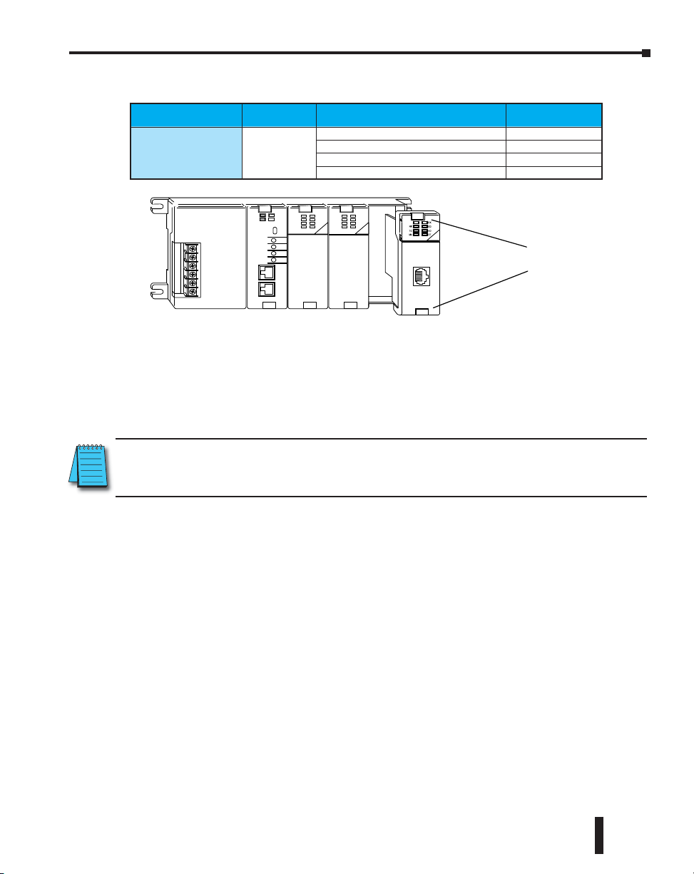
ECOM Module Introduction
Several Ethernet Communication (ECOM) modules are currently available for use with
DL05/06, DL205 and DL405 PLC systems. The ECOM modules are shown below. These
modules provide a low-cost, high-speed Ethernet link for PLC systems. The modules are easy
to set up and install on 10/100BaseT (twisted pair, copper wire) or 10BaseFL (fiber optic)
Ethernet networks.
LEDs on the face of each module give vital information about the status of the module and the
communication link. The 10/100BaseT modules use standard RJ45 modular connectors, and
the 10BaseFL modules use ST style bayonet connectors.
DL05/06 ECOM Modules
H0-ECOM
H0-ECOM100
H0-ECOM100
NOTE: If you are using a D0-06LCD in your DL06 PLC, the date code for the display unit must be 032A_ or
later to be compatible with the H0 series ECOM modules.
DL205 ECOM Modules
H2-ECOM
H2-ECOM100
H2-ECOM-F
H2-ECOM100
DL405 ECOM Modules
H4-ECOM
H4-ECOM100
H4-ECOM-F
H4-ECOM100
ECOM Communication Possibilities
You can use the ECOM modules to share data between two or more DirectLOGIC PLCs
or between DirectLOGIC PLCs and personal computers. The H0/H2/H4 -ECOM100
additionally allows client/server communications with other Ethernet devices using the
MODBUS TCP protocol. Communication between PLCs/MODBUS TCP devices is
accomplished by using the Read/Write (RX/WX) instructions which are available in the
DirectSOFT Programming Software Users Manual. Chapters 4 and 5 explain the use of the
RX/WX instructions.
1–4
NOTE: Please review intelligent instructions (IBox) in Chapter 5 of the user manual for the PLC you are
using, which simplify this and other functions.
Ethernet Communications Modules, 3rd Edition, Rev. E
Page 17
Chapter 1: Introduction
You can also use a personal computer running DirectSOFT Programming Software to program
your PLCs over the Ethernet network. It is just like programming through the programming
port on the CPU, but with the convenience of doing it from a single location.
Use DirectSOFT programming software to program the complete DirectLOGIC family of PLCs
(the DL105 and DL305 series are the only PLCs that cannot be programmed over Ethernet).
Chapter 2 will indicate the CPUs which can be used with the ECOM modules.
NOTE: We recommend using a dedicated network for your PLC control applications. For more information
see Chapter 2, Setup and Installation
Your Network PC
PCs running our KEPDirect for PLCs software can establish Ethernet links for exchanging
information with DirectLOGIC 05/06/205/405 PLCs.
You can use a personal computer equipped with a 10/100BaseT or 10BaseFL network adapter
card and NetEdit3 software to configure the ECOM module over the network. You can also use
NetEdit3 for troubleshooting certain communication problems. The NetEdit3 utility is available
for download at http://www.automationdirect.com.
Ethernet Communications Modules, 3rd Edition, Rev. E
1–5
Page 18

Chapter 1: Introduction
Frequently Asked Questions
.Q How can I speed up my ECOM communications?
.A Try shortening the scan time of the PLC (the PLC allows
only one ECOM transaction per scan).
.Q What causes “Task code error response” with extended E353 error?
.A Error is from the PLC and means “timeout in the background communications”.
Error is due to a backplane communication problem (ECOM, DCM, etc.).
.Q Can an ECOM be configured to talk through a gateway?
.A Yes. You configure the gateway to reroute traffic to
and from the ECOM via port 7070 (hex).
.Q When using a DL205 with an ECOM, is there a way to turn on the PLC
outputs from a computer using a non- Windows operating system?
.A Host Engineering has what is called an Ethernet SDK (software developers
kit) which can normally be downloaded (free) from their website. However,
this will be useless for your system, but to accommodate your operating
system, you can fill out a form located on the Host Engineering website
and request the source code for the Ethernet SDK. This is necessary
so that Host Engineering will know who is using their source code.
The source code can then be recompiled to work on your system.
With the SDK recompiled for your system, you can use CCM (i.e.
DirectNET) protocol to turn on PLC outputs by simply knowing
the memory types and ranges as required for syntax.
The request form and details about the SDK can be found on the Host
Engineering homepage (www.hosteng.com). Once there, click on “EBC/
ECOM/EDRV” under “S/W Developer Kits” in the left- hand column.
.Q What is the fastest way to get data from PLC to PLC?
.A Install ECOM in both PLCs and use the RX/WX commands is the quickest
way to do this. It is much faster that using serial communication.
.Q Can the ECOM do a broadcast message to multiple slave devices?
.A No.
.Q Can the MAC address be changed?
.A The MAC address is burned into ROM on the module and is set just before it
leaves the factory. There is no logical way for any protocol to change this address.
Host Engineering’s range for Ethernet (MAC) addresses is 00.E0.62.xx.xx.xx.
1–6
Ethernet Communications Modules, 3rd Edition, Rev. E
Page 19

Chapter
Chapter
Chapter
Setup and InStallatIon
2
2
1
In This Chapter...
ECOM Network Identifiers ........................................................................................2–2
Setting the Module ID with the DIP Switch ............................................................. 2–5
Inserting the ECOM Module in the PLC Base ...........................................................2–7
ECOM Network Layouts ..........................................................................................2–10
Network Cabling ......................................................................................................2–12
Maximum Cable Length .......................................................................................... 2–14
Maximum Number of ECOM Modules on the Network ........................................2–15
Page 20

Chapter 2: Setup and Installation
ECOM Network Identifiers
This section describes network identifiers that can be assigned to the ECOM module. Each
module must be assigned at least one unique identifier to make it possible for PCs or other
ECOMs to recognize it on the network. Four methods of identifying the ECOM module give
it the flexibility to fit most networking schemes.
The four ECOM identifiers are:
• Module ID
• Name
• IP (Internet Protocol) Address
• Ethernet (MAC) Address
The first three are user-selectable. The last one is set at the factory. Each of the identifiers is
discussed in this chapter. If you have more than a few ECOMs on your network, consider
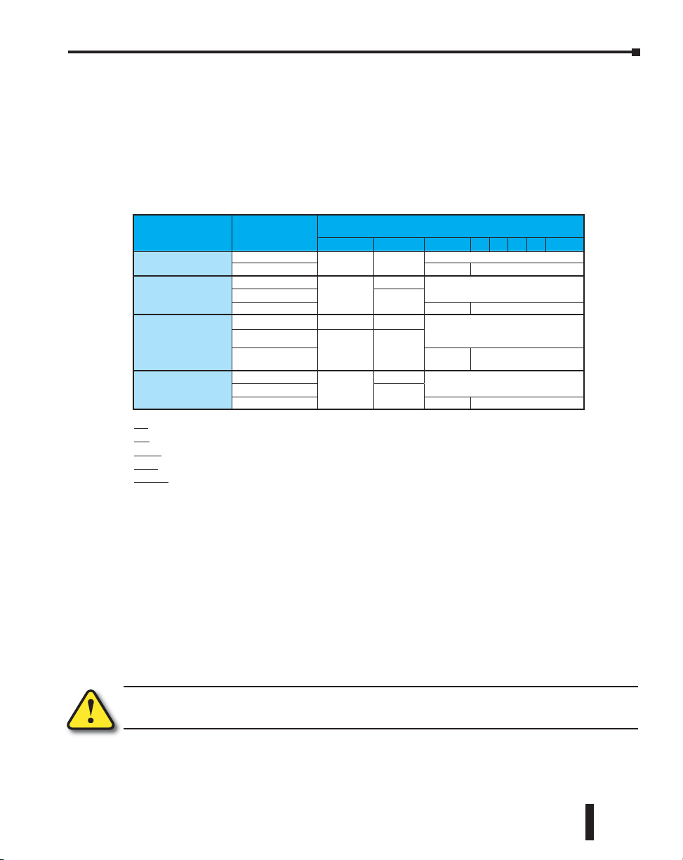
making a chart or spreadsheet of network IDs, as shown below:
Ethernet (MAC) Address Module ID Name IP Address
00 E0 62 20 01 20
00 E0 62 20 01 58
00 E0 62 20 01 8D
00 E0 62 20 01 94
00 E0 62 20 01 DE
00 E0 62 20 01 F1
00 E0 62 20 01 FB
00 E0 62 20 01 F0
The decision about which type of identifier to use is an important one. Much of the decision
depends on the requirements of your particular application. PC-to-PLC communications are
generally better accommodated with one type of identifier while PLC-to-PLC communications
require a different type. Ease of maintenance and troubleshooting also must be considered
before deciding which type to use.
The identifiers are used to link your PC to your PLC or one PLC to another PLC. The flexible
design of the module allows you to use different identifiers for different links to the same
module. This is particularly important if you require both PC-to-PLC and PLC-to-PLC
communications on the same network.
The following table summarizes Network Identifiers and their uses:
17 BldgThree 192.168.100.001
61 192.168.100.003
33 192.168.100.004
3 PumpStationTwo 192.168.100.005
8 Effluent 255.255.255.255
2 PumpStationOne 192.168.100.002
1 Control Room 255.255.255.255
5 Mixer 192.168.100.006
2–2
How to Set Format Communication Restrictions/Notes
Module ID
Name
IP Address
Ethernet (MAC)
Address
DIP Switch Number 1–63
NetEdit3 Number 1–90
NetEdit3 Number 1–999,999,999
NetEdit3
NetEdit3
Set at Factory 12 Hex digits PC to PLC only Factory assigned, for IPX
32 Alphanumeric
Characters
4 Three-digit Numbers,
xxx.xxx.xxx.xxx
(See page 2-4)
PLC to PLC or
PC to PLC
PC to PLC only
PC to PLC; (PLC to PLC
- Client/Server using
TCP/IP or Modbus TCP
protocol)
Ethernet Communications Modules, 3rd Edition, Rev. E
Disables Module ID in
NetEdit3
DIP switch must be set
to “0”
>90 (Not for PLC to PLC)
HMI software may have
restrictions
See you network
administrator for IP address;
(refer to pages 3-10 to 3-11,
chapters 5 & 6)
Page 21

Chapter 2: Setup and Installation
Module ID
A Module ID is required for PLC-to-PLC communications, and it can be set either of two
ways. You can assign the Module ID:
• Using the DIP switches on the module.
• Using the configuration tools in NetEdit3
• HTML Configuration (after IP address is assigned to module using
NetEdit3; described in Chapter 5; H0/H2/H4- ECOM100 only)
Use the DIP switch if you want the ability to install or change modules without using a PC to
set the Module ID. Set the module’s DIP switch, insert the module in the base, and connect the
network cable. Your Module ID is set on powerup, and your ECOM is ready to communicate
on the network. We step through setting the DIP switch on pages 2-5 and 2-6.
8 7 6 5 4 3 2 1
ON
7 6 5 4 3 2 1 0
Name
If you prefer to be able to set or change all Module IDs on your network from a single PC, use
the tools in NetEdit3, discussed in chapter 3.
A Name makes it easy to recognize the PLC by its function. An example of a Name is
“PumpStationOne.” The Name can be up to 32 alphanumeric characters in length. A Name
can be assigned using NetEdit3.
Pump Station One
PUMP STATION ONE
NOTE: Some HMI software products will not accept Names with numbers as the first character, spaces or
certain other non-alphanumeric ASCII characters. Also, your HMI product may not accept Names longer
than 16 characters. Consult your HMI product documentation about its naming conventions
Ethernet Communications Modules, 3rd Edition, Rev. E
2–3
Page 22
Chapter 2: Setup and Installation
An IP Address can be assigned to the ECOM module if your network requires one. Usually, the
IP Address is required in cases where PLCs are sharing the same network with PCs, and some of
the PCs are carrying out functions unrelated to PLC control. Normally, a network administrator
will assign an IP Address to each device on the network. If you have a separate dedicated
network for your PLCs, you can use the Module ID or a Name for each communication link.
You must use an IP Address, if you are using the UDP/IP or MODBUS TCP protocol.
Use NetEdit3 to assign an IP address to the ECOM (refer to chapter 3).
The module ships from the factory with an IP Address of 0.0.0.0. This is not a usable IP
Address for normal communications. It only serves as a default setting which can be changed
using NetEdit3. Valid settings are 1 through 254. You do not have to change the default IP
Address unless you are using the IP Address to link to your ECOM module. The default setting
does not cause conflicts with other network communications.
If you change the default IP Address for linking to other network devices, you must change all
four “0” fields. If any field contains the number 255 and other fields have been changed, the
module will not be recognized on the network.
Example:
Client (PC/ECOM) Subnet Mask: 255.255.0.0
Valid Client (PC/ECOM) IP Address: 192.168.50.2
Valid Server ECOM IP Address: 192.168.55.5
Valid Server ECOM IP Address: 192.168.70.15
1–254 Valid settings for Bold number
fields (Do not duplicate).
2–4
WARNING: It is extremely important not to have duplicate IP Addresses on your network. If you are
using the IP Address to link the ECOM to any network devices (PCs or PLCs), the ECOM must have a
unique number.
Ethernet (MAC) Address
A unique Ethernet (MAC) Address is assigned to each module at the factory and will not
change. It is printed on a label attached to each ECOM module. The Ethernet (MAC) Address
is recognized by NetEdit3. The Ethernet (MAC) Address is a twelve digit number with no
deliberate relationship to your network or functional areas of your plant. It does not usually
serve as a convenient and easily remembered identifier for your ECOM.
Using Multiple Network Identifies
You can use the IP Address to satisfy network requirements, a Name for PCs running HMI
software and the Module ID for PLCs to share data among themselves. Using one type of
identifier does not limit your use of the other identifier types.
Ethernet Communications Modules, 3rd Edition, Rev. E
Page 23
Chapter 2: Setup and Installation
Setting the Module ID with the DIP Switch
The ECOM’s DIP switches contain eight individual slide switches, but not all of these are
active. The individual slide switches are labeled 1 through 8 on the body of the DIP switch
(upside down in the following figures).
You will find that the printed circuit board is labeled 0 (zero) through 7. We use the labeling
on the printed circuit board in describing how to set the switch. The table below shows the
meaning of each dipswitch based on the version of the module being used.
Module Type
H0-ECOM
H0-ECOM100
H2-ECOM
H2-ECOM-F
H4-ECOM
H4-ECOM-F
H2-ECOM100
H4-ECOM100
RBE (Report by Exception) - Dipswitch must be ON for this function.
IBox (Intelligent Boxes) - Dipswitch must be ON for the ECxxxxx IBoxes to Function.
Recover - Dipswitch used to reset IP settings back to factory default on power-up in case device is lot on network.
Protect - Dipswitch must be ON to write protect firmware and network, node, peer-to-peer, SMTP (email) configurations.
Module ID - Bit-weighted for manual setting of this parameter.
Release
Version
v1.0.354
v1.0.364 Protect Module ID
v4.0.49
v4.0.167
v4.0.320 Protect Module ID
v1.0.7
v1.0.147
v1.0.227 Protect Module ID
v4.0.877
v4.0.1237
v4.0.1735 Protect Module ID
7 6 5 4 3 2 1 0
RBE
RBE/IBox
RBE
RBE/IBox
Recover
Recover
Dipswitch
Module ID
Module ID
Module ID
Module ID
The dipswitch numbers on the printed circuit board indicate the power of 2 represented by
each slide switch. For example, switch 0 represents 20 (or 1), switch 1 is 21 (or 2), switch 2 is 22
(or 4), and so on. The following figures show the binary value of each switch in parentheses ( ).
You can use the DIP switch on the ECOM module to set the Module ID to a number from
1 to 63. Each module on a given network must be assigned a unique Module ID if the Module
ID is to be used for communications. Do not use Module ID “0” for communications.
If the DIP switch is set to a number greater than 0, the software tools are disabled from setting
the Module ID. The software tools will only allow changes to the Module ID if the DIP switch
setting is 0 (zero, all switches OFF). The DIP switch settings are read at powerup. You can use
the software tools to set the Name and IP Address even if you use the DIP switch for setting
the Module ID.
WARNING: Using duplicate Module IDs on a single network will cause unreliable PLC-to-PLC
communications.
Ethernet Communications Modules, 3rd Edition, Rev. E
2–5
Page 24
Chapter 2: Setup and Installation
H0 / H2 Series ECOM DIP Switch
If using the ECOM/ECOM100 module with Dataworx software, or the ECOM100 with
IBox Communication instructions, then dipswitch 7 must be set to ON.
The Module ID equals the sum of the binary values of the slide switches set in the ON position.
For example, if you set slide switches 1, 2, and 3 to the ON position, the Module ID will be
14. This is found by adding 8+4+2=14. The maximum value you can set on the DIP switch
is 32+16+8+4+2+1=63. This is achieved by setting switches 0 through 5 to the ON position.
2–6
Ethernet Communications Modules, 3rd Edition, Rev. E
Page 25
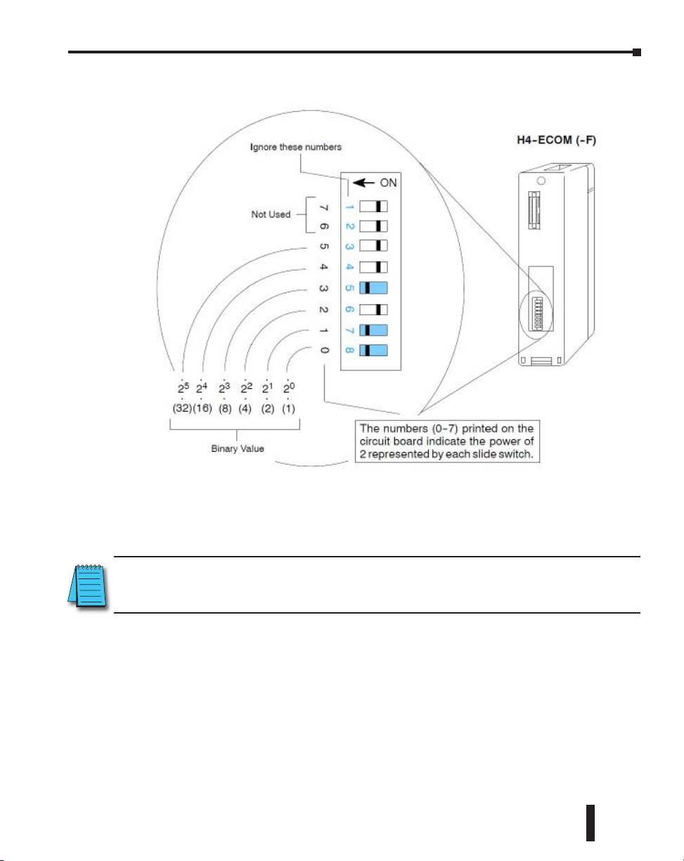
H4 Series ECOM DIP Switch
Chapter 2: Setup and Installation
The Module ID equals the sum of the binary values of the slide switch set in the ON position.
For example, if you set slide switches 0, 1, and 3 to the ON position, the Module ID will be
11. This is found by adding 8+2+1=11. The maximum value you can set on the DIP switch
is 32+16+8+4+2+1=63. This is achieved by setting switches 0 through 5 to the ON position.
NOTE: When all the switches are set to OFF (Module ID = 0), the Module ID can be set using the software
utilities in NetEdit and DirectSOFT. Do not use Module ID “0” for normal communications. It is okay to
leave the Module ID set at zero if you are using the Name or IP Address for communications
Ethernet Communications Modules, 3rd Edition, Rev. E
2–7
Page 26
Chapter 2: Setup and Installation
Setup and
Installation
2--7
Setup and Installation
Setup and
Installation
Installation and
Safety Guidelines
2--7
Setup and Installation
Pinch Tabs
C0 C4C2X1 X3 X4 X6 X11X13X14 X16 X21X23N.C.
C1 C3X2 X5 X7 X10 X12 X15X17 X20X22X 0 N.C.
AC(N)24V
0V
N.C.
C1 C3Y0 Y15Y12Y10 Y17Y7Y5Y2
C0 C2 Y16Y14Y13Y 11Y6Y4Y3Y1
LGG
AC(L
)
2.0AOUTPUT:6--240V
50 --60Hz2.0A,6 -- 27V
INPUT:12 -- 24V3 --15mA
Y
X
40VA50--60HzPWR: 100--240V
0 1 2 3 4 5 6 7 10 11 12 13 14 15 16 17 20 2122 23
PORT1 RUN STOP
PWR
RUN
CPU
TX1
RX1
TX2
RX2
D0--06DR
PORT2
TERM
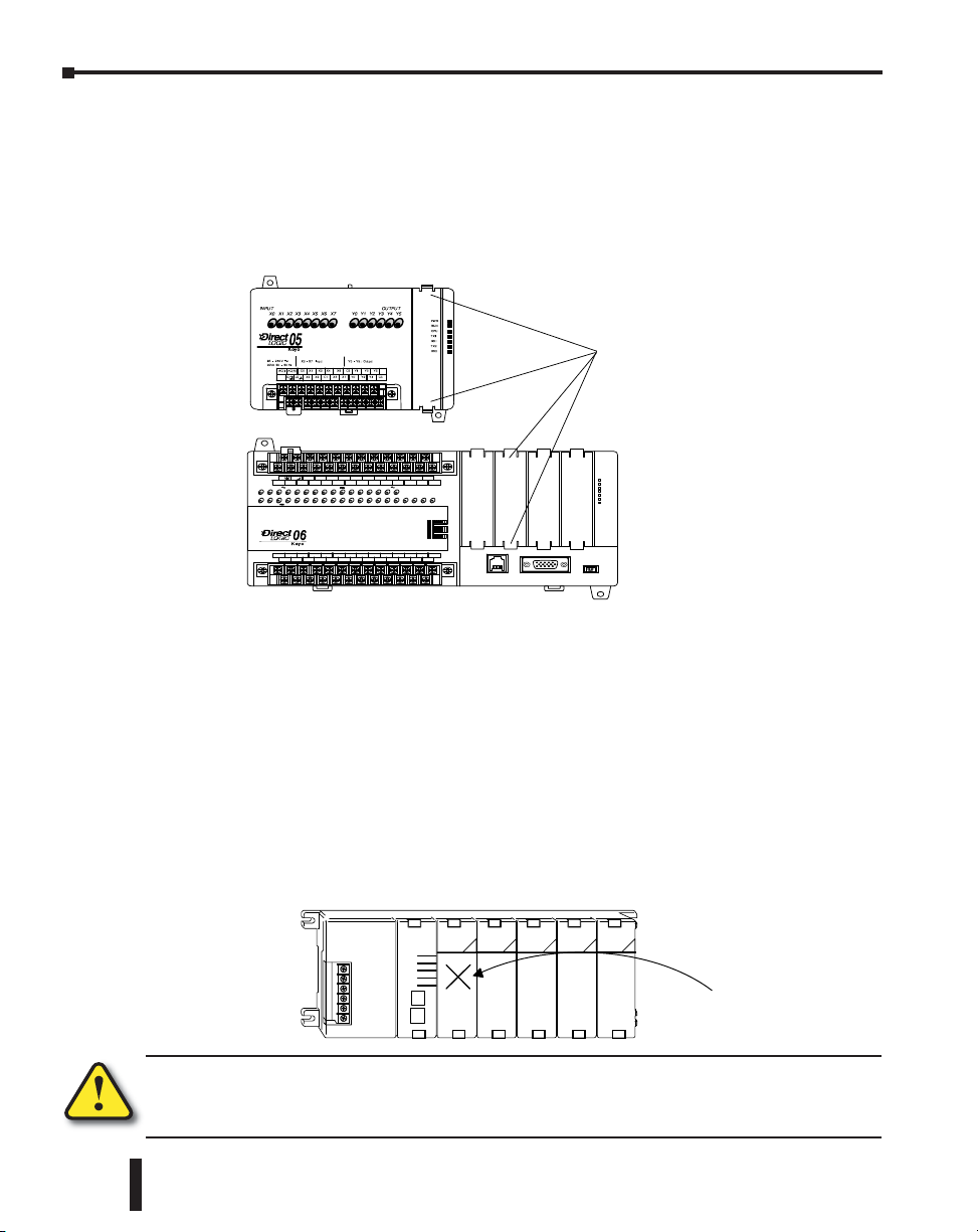
Inserting the ECOM Module in the PLC Base
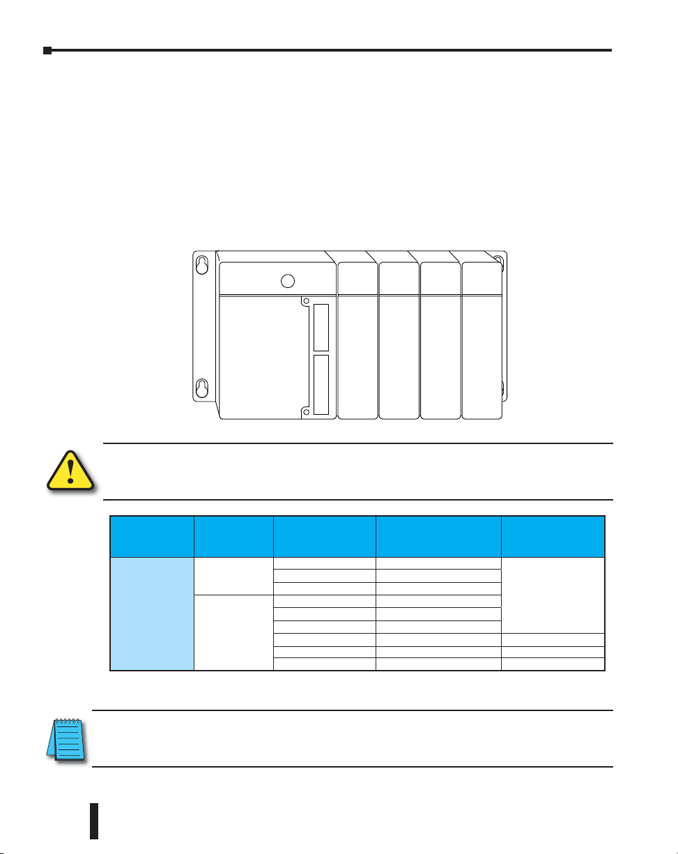
H0 Series ECOM Module Installation
Before installing the option module in the DL05 option slot or any of the DL06 option slots,
set the Module ID dip switch (if your application requires this) on the H0 Series ECOM
module. Verify power to the PLC is turned off. The next step is to remove the protective option
slot cover. Remove the cover by squeezing the pinch tabs and lifting the cover off
Pinch Tabs
DL205 Slot Choices
C1 C3Y0 Y15Y12Y10 Y17Y7Y5Y2
LGG
0V
)
C0 C2 Y16Y14Y13Y11Y6Y4Y3Y1
AC(N)24V
AC(L
Y
0 1 2 3 4 5 6 7 10 11 12 13 14 15 16 17 20 21 22 23
X
INPUT:12 --24V3-- 15mA
C0 C4C2X1 X3 X4 X6 X11X13X14 X16 X21X23 N.C.
Now, insert the module into the open slot on the DL05 or into any one of the four slots in the
2.0AOUTPUT:6 --240V
50 -- 60Hz2.0A,6 -- 27V
C1 C3X2 X5 X7 X10 X12 X15X17X20 X22X 0 N.C.
N.C.
40VA50--60HzPWR: 100--240V
D0--06DR
PORT1 RUN STOP
PORT2
DL06. Locate the module so the printed information is oriented in the same direction as the
markings on the PLC. Be careful to align the female connector on the printed circuit board of
the module with the male connector on the PLC mother board. Press the module into the slot
until the front of the module is flush with the front of the PLC. Check the DL06 power budget
to be sure that it remains within the power supply limits before installing more modules.
The DL205 system supports placement of the ECOM module in the CPU-base only, not in
local expansion bases or remote I/O bases. The number of usable slots depends on how many
slots your base has. The module does not work in slot 0 of the DL205 series PLCs, the slot
next to the CPU. The D2-240, D2-250-1, D2-260 and D2-262 CPUs support the ECOM
modules. The D2-230 CPU does not support the ECOM modules.
CPU
205
PWR
RUN
CPU
TX1
RX1
TX2
RX2
TERM
2–8
Slot 0 Slot 1 Slot 2 Slot 3 Slot 4
No!
WARNING: Your system can be damaged if you install or remove system components before disconnecting
the system power. To minimize the risk of equipment damage, electrical shock, or personal injury,
always disconnect the system power before installing or removing any system
Ethernet Communications Modules, 3rd Edition, Rev. E
Page 27
Chapter 2: Setup and Installation
H2 Series ECOM Module
Module Type CPU CPU - Base Usuable Slots
H2-ECOM
H2-ECOM100
H2-ECOM-F
D2-240 D2-03B-1, D2-03BDC1-1, D2-03BDC-2 1
D2-250-1 D2-04B-1, D2-04BDC1-1, D2-04BDC-2 1, 2
D2-260 D2-06B-1, D2-06BDC1-1, D2-06BDC-1 1, 2, 3, 4
D2-262 D2-09B-1, D2-09BDC1-1, D2-09BDC-1 1, 2, 3, 4, 5, 6, 7
205
Retaining Clips
Before installing the module, verify power to the PLC is turned off. To install the ECOM
module, line up the module’s printed circuit board with the grooves in the base and push
the module until it is flush with face of the DL205 base power supply. If you feel more than
moderate resistance when you push the module into the base, the circuit board may not be
aligned with the grooves in the base. When the module is firmly seated in the slot, depress the
top and bottom retaining clips to lock the module in place.
NOTE: When adding modules to your PLC always confirm that your power budget will accommodate the
added module. See the User Manual for your PLC for more information about calculating the power budget.
See Appendix A for the power consumption of the ECOM modules.
Ethernet Communications Modules, 3rd Edition, Rev. E
2–9
Page 28
Chapter 2: Setup and Installation
DL405 Slot Choices
For PLC systems with D4-430 and D4-440 CPUs, the ECOM modules can reside in any I/O
slot but only in the CPU-base. The D4-450 and D4-454 CPUs allows the installation of the
ECOM module in the CPU-base or in local expansion bases. However, it is still recommended
the ECOM be installed on the CPU base.
If the ECOM module is used in a local expansion base, all bases in the system must be the “-1”
type bases. The valid part numbers for these bases are D4-04B-1, D4-06B-1, and D4-08B-1.
The “-1” on the end of the part number indicates that the base supports specialty modules
including the ECOM. The “-1” bases can be connected as local expansion bases or remote
bases. They are not the same thing. Remote bases do not support the ECOM modules.
405
CPU
Slot 0 Slot 1 Slot 2
Slot 3
2–10
WARNING: Your system can be damaged if you install or remove system components before disconnecting
the system power. To minimize the risk of equipment damage, electrical shock, or personal injury,
always disconnect the system power before installing or removing any system component.
Module Type CPU Base
D4-04B, D4-04B-1 0, 1, 2, 3
D4-430/D4-440
H2-ECOM
H2-ECOM100
H2-ECOM-F
* You must use the “- 1” base for the CPU-base and all local expansion bases.
NOTE: Before installing the ECOM module, confirm that your power budget will accommodate the added
module. See the DL205 or DL405 User Manual for your PLC for more information about calculating the
power budget. See Appendix A for the power consumption of the ECOM modules.
D4-450/D4-454
D4-06B, D4-06B-1 0, 1, 2, 3, 4, 5
D4-08B, D4-08B-1 0, 1, 2, 3, 4, 5, 6, 7
D4-04B 0, 1, 2, 3
D4-06B 0, 1, 2, 3, 4, 5
D4-08B 0, 1, 2, 3, 4, 5, 6, 7
D4-04B 0, 1, 2, 3 0, 1, 2, 3*
D4-06B 0, 1, 2, 3, 4, 5 0, 1, 2, 3, 4, 5*
D4-08B 0, 1, 2, 3, 4, 5, 6, 7 0, 1, 2, 3, 4, 5, 6, 7*
Available
CPU-Base Slots
Available
Expansion Base
Slots
N/A
Ethernet Communications Modules, 3rd Edition, Rev. E
Page 29
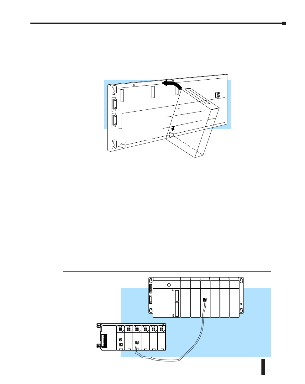
H4 Series ECOM
Before installing the ECOM module, verify power to the PLC is turned off. To insert the
ECOM module in a DL405 base, place the bottom tab of the module into Module Installation
the notch at the bottom of the base. Pivot the module toward the base as shown below. Ensure
that each module is tightly seated and secured with the captive screw at the top of the module.
DL405 Base
Disconnect power before installing module!
ECOM Network Layouts
The ECOM Ethernet network is a peer-to-peer network. Using Read (RX) or Write (WX)
instructions, any PLC on the network can initiate communications with any other PLC on the
network. A PC running our KEPDirect for PLCs software can also initiate communications
with any ECOM that is on the same network, but a PLC cannot initiate communication with
the PC. A PLC cannot literally broadcast to all other PLCs at the same time, but a PLC can
sequence through communication connections with other PLCs on the network, one at a time.
The ECOM products inherently support two network layouts: point-to-point and star. The
point-to-point layout can be used to link together two PLCs or a PC and a PLC. A hub or
repeater connects multiple network capable devices into a star topology. Multiple hubs or
repeaters are used to modify the star topology so that it becomes a star-bus-star topology. See
the figures below and on the next page.
Chapter 2: Setup and Installation
Point-to-Point
Point-to-Point
Ethernet Communications Modules, 3rd Edition, Rev. E
2–11
Page 30
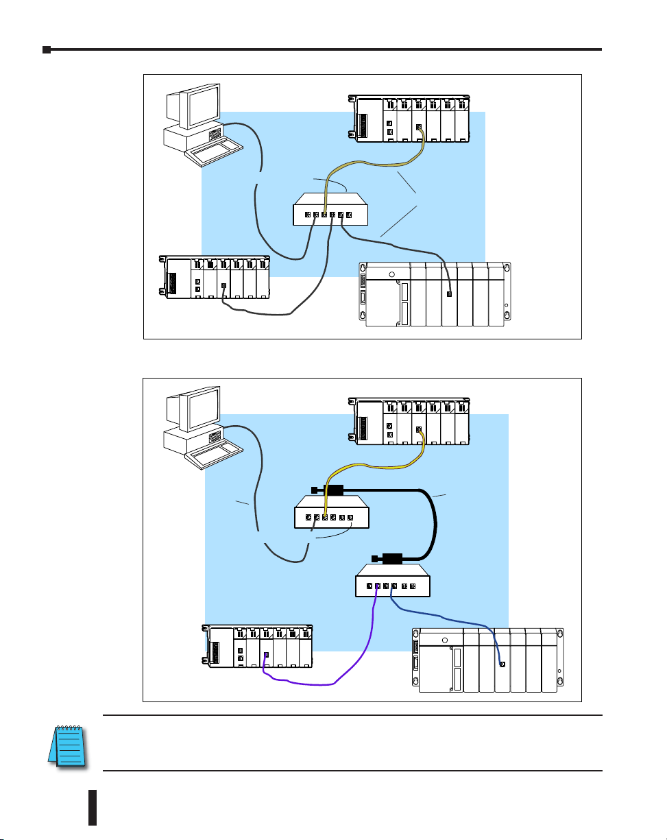
Chapter 2: Setup and Installation
Hub or Repeater
Star Topology
10/100BaseT
or
10BaseFL
Hubs or repeaters can connect together to make it possible to connect more devices to the
network or to extend the range of the network
10BaseT
or
10BaseFL
Hub or Repeater
Star-Bus-Star Topology
Any Backbone
10Base2
10Base5
10BaseT
100BaseT
10BaseFL
2–12
NOTE: Hubs or repeaters often designate one port for uplink to another hub. This port may not be able
to be used to connect to a PLC. If the uplink port is used to connect to another hub, it may disable the
adjacent port. Use of the uplink port may require the use of a crossover cable.
Ethernet Communications Modules, 3rd Edition, Rev. E
Page 31

Network Cabling
ECOM Supports Two Standards
Two types of ECOMs are available. One type supports the 10/100BaseT cabling standard, and
the other supports the 10BaseFL connection standard. The 10/100BaseT standard uses twisted
pairs of copper wire conductors, and the 10BaseFL standard is for fiber optic cabling.
Chapter 2: Setup and Installation
10/100BaseT
Unshielded
Twisted-Pair
cable with RJ45
connectors
10BaseFL
62.5/125 MMF
fiber optics cable
with ST-style
connectors
10/100BaseT Networks
The cable used to connect a PLC (or PC) to a hub or repeater is called a patch (straightthrough) cable. The cable used to connect together two PLCs, or a PC and a PLC or two hubs
is a crossover cable. We recommend that you purchase cables pre-assembled with connectors for
convenient and reliable networking.
The above diagrams illustrate the standard wire positions in the RJ45 connector. We recommend
all ECOM 10/100BaseT cables to be Category 5, UTP cable.
Ethernet Communications Modules, 3rd Edition, Rev. E
2–13
Page 32

Chapter 2: Setup and Installation
Ferrule
10/100BaseT Connections
Most 10/100BaseT hubs or repeaters use a patch (straight-through) cable for connecting the
network devices (PLCs or PCs). For hub-to-hub connections a crossover type cable is commonly
required. The figures on the previous page show pin assignments and insulation color codes for
patch (straight-through) and crossover type Ethernet cables.
UTP Cable
The ECOM has an eight-pin modular port that accepts RJ45 type connectors. UTP (Unshielded
Twisted-Pair) cable is rated according to its data-carrying ability (bandwidth) and is given a
“category” number. We strongly recommend using a category 5 cable for all ECOM connections.
NOTE: See page 2-14 for 10/100BaseT cable distance limitations.
10BaseFL Connections
Each module has two bayonet ST-style connectors. The ST-style connector uses a quick
release coupling which requires a quarter turn to engage or disengage. The connectors provide
mechanical and optical alignment of fibers.
Each cable segment requires two strands of fiber: one to transmit data and one to receive data.
The ST-style connectors are used to connect the H2-ECOM-F or H4-ECOM-F module to
another H2-ECOM-F or H4-ECOM-F module or a fiber optic hub or repeater.
Fiber Optic Cable
The H2-ECOM-F and H4-ECOM-F modules accept 62.5/125 multimode fiber optic (MMF)
cable. The glass core diameter is 62.5 micrometers and the glass cladding is 125 micrometers.
The fiber optic cable is highly immune to noise and permits communications over much greater
distances than 10BaseT.
Fiber Optic Module ST Connector
Multimode Fiber Optic (MMF) Cable
Transmit
Fiber Cross-section
Sheathing
2–14
Receive
NOTE: See page 2-14 for 10BaseFL distance limitations
62.5/125 MMF cable with
bayonet ST-style connectors
Connecting Two
Transmit
Receive
Fiber Optic ECOMs
Ethernet Communications Modules, 3rd Edition, Rev. E
Core
Cladding
Transmit
Receive
Page 33

Maximum Cable Length
The maximum distance per 10/100BaseT cable segment is 100 meters or 328 feet. Repeaters
extend the distance. Each cable segment attached to a repeater can be 100 meters. Two repeaters
connected together extend the total range to 300 meters.
10/100BaseT Distance Limitations
Chapter 2: Setup and Installation
100 meters
(328 feet)
100 meters
(328 feet)
100 meters
(328 feet)
100 meters
(328 feet)
100 meters
(328 feet)
Between
Repeaters
The maximum distance per 10BaseFL cable segment is 2,000 meters or 6,560 feet. Repeaters
extend the distance. Each cable segment attached to a repeater can be 2,000 meters. Two
repeaters connected together extend the total range to 6,000 meters.
10BaseFL Distance Limitations
2,000 meters
(6,560 feet)
2,000 meters
(6,560 feet)
2,000 meters
(6,560 feet)
2,000 meters
2,000 meters
(6,560 feet)
Between
Repeaters
(6,560 feet)
Ethernet Communications Modules, 3rd Edition, Rev. E
2–15
Page 34

Chapter 2: Setup and Installation
Maximum Number of ECOM Modules on the Network
The maximum number of nodes that can be connected to a 10/100BaseT or 10BaseFL network
is a function of the topology used in constructing the network. Therefore, it is not possible to
state an absolute maximum number of nodes that would apply in all cases.
The IEEE 802.3 specification defines the maximum node limit for an Ethernet segment in
terms of the ability to detect and avoid data collisions. A “legal” network can have any number
of devices provided that they can:
• Detect all data collisions that may occur during the communication process and
• Respond to these collisions appropriately.
You must take into consideration the network limitations imposed by all cabling and network
devices. Consider the limitations imposed on your network if your network uses:
• A combination of cabling standards, such as 10/100 BaseT and 10Base2, or
• Intermediate devices, such as switches or routers.
Each ECOM module can be assigned a Module ID ranging from 1 to 999,999,999.
Theoretically, you could have this many Ethernet modules coexisting on a single network. Other
network limitations would restrict the network size before reaching this limit. For the majority
of network PLC applications there is practically no limit to the number of ECOM modules
you can access from the NetEdit3, DirectSOFT Programming Software or the KEPDirect for
PLCs software.
There is a node limit for PLC-to-PLC communications. The network Read and Write
instructions performed by the initiating (master) PLC are only capable of accessing PLCs with
Module IDs of 1 through 90. This effectively sets the maximum number of nodes available for
PLC-to-PLC communications at 90.
2–16
WARNING: We recommend against connecting Ethernet modules to the same network that serves as your
primary office network. While Ethernet networks can handle a very large number of data transmissions,
and normally handle them very quickly, heavy Ethernet traffic can adversely affect the reliability and
speed of the network.
Ethernet Communications Modules, 3rd Edition, Rev. E
Page 35

Configuring ECoMs
Chapter
Chapter
Chapter
using nEtEdit3
In This Chapter...
NetEdit3 Software .....................................................................................................3–2
NOTE: Please reference the BRX MPU system user manual (BX-USER-M) Appendix E for an updated guide
to using the NetEdit utility. This manual can be downloaded at www.automationdirect.com. For the latest
version and information on NetEdit, please visit www.hosteng.com, under the Utilities and FAQs sections.
3
3
3
Page 36

Chapter 3: Configuring ECOMs Using NetEdit3
NetEdit3 Software
NetEdit3 is a software utility which can be used to set network identifiers (Module ID or IP
Address), perform diagnostic and troubleshooting tasks and upgrade the firmware in the ECOM
module if necessary. The H0/H2/H4 -ECOM100 requires NetEdit 3.5 or later.
Installing NetEdit3
You can install NetEdit3 on Windows98/ME/2000/XPt or Windows NT4t. NetEdit3 is
available online at www.automationdirect.com. After loading the software the following window
will appear.
Click on Install NetEdit3. A series of windows will step you through the installation process.
3–2
Click on the Essential Tools button. The following window will be displayed.
Fill in the necessary information as the installation wizard prompts through the install. In the
Setup Type window, select Typical setup. This setup type is recommended for most users. The
installation process places NetEdit3 in the C:\HAPTools directory (default).
Ethernet Communications Modules, 3rd Edition, Rev. E
Page 37

Chapter 3: Configuring ECOMs Using NetEdit3
Launching NetEdit3
There are three methods to launch NetEdit3. The three methods are:
• using the Windows Start menu Programs>AutomationDirect Tools> NetEdit3
as shown below
• launching DirectSoft (if installed), from the programming window, select
PLC>Tools>NetEdit3
• launching DirectSoft (if installed), then select Utilities>NetEdit3
The NetEdit3 Screen
Starting NetEdit3 brings up the screen below. All NetEdit3 functions are accessed
from this screen.
Ethernet Communications Modules, 3rd Edition, Rev. E
3–3
Page 38

Chapter 3: Configuring ECOMs Using NetEdit3
Adding Network Protocol Support to the NetEdit3 PC
You may have already set up your PC with selected networking protocols for Ethernet
communications. If not, you will need to select the protocols now for communication with the
Ethernet modules. We strongly recommend that you include the IPX protocol. For Windows
2000, go from My Computer on your Windows desktop to Control Panel. Double click on
Network and Dial- up Connections, then double click on the desired Network Device to see
the installed Protocols. If IPX is not listed among the protocols already loaded, add it now by
clicking on the Install button. For Windows XP, go from Start>Settings>Control Panel. The
steps are the same as Windows 2000 from this point.
Add the TCP/IP protocol if it is necessary for your application. The TCP/IP selection will give
you support for the UDP/IP protocol. Also, add the IPX protocol if it is not already active.
3–4
NOTE: We strongly recommend you load IPX protocol on your PC for the connection from your PC to
the Ethernet modules. Use UDP/IP in your application, if required, but also add IPX to your list of active
protocols. Having IPX loaded on your PC gives you a backup for troubleshooting communication problems.
Ethernet Communications Modules, 3rd Edition, Rev. E
Page 39

Chapter 3: Configuring ECOMs Using NetEdit3
Using NetEdit3
This section steps through the features and uses of NetEdit3. We will describe the individual
segments of the NetEdit3 screen and the function of each.
NOTE: Your PC-based Control software may be capable of configuring the EBC module. If so, please refer to
the appropriate documentation for that software product to determine the best method to configure the EBC.
Depending on which software you are using, it may not be necessary to use NetEdit3.
Ethernet Communication Protocol
In the upper left corner of the NetEdit3 screen, you will find buttons labeled IPX and TCP/IP.
The ECOM module understands these protocols. Both protocols are permanently resident in
the firmware of the module.
When you click on one of these buttons, you are selecting the protocol you want your PC to use
to communicate with the ECOM module. You are not telling the module which protocol to use,
because it is using both protocols all the time. IPX is a Novell standard in widespread use, and
UDP/IP is a popular protocol supported by the TCP/IP suite of protocols in your PC.
The figure to the right shows the Protocol
selection buttons in the upper left corner
of the NetEdit3 screen. The choice you
make here tells your PC which protocol to
send to the ECOM to link NetEdit3 to the
module.
Some PC-based control software products
may support only one of these protocols.
Read the documentation for your software
to be sure the protocol you select is
supported.
Ethernet Communications Modules, 3rd Edition, Rev. E
3–5
Page 40

Chapter 3: Configuring ECOMs Using NetEdit3
Ethernet Address
The upper left section of the NetEdit3 screen displays
the Ethernet Address of the modules currently on the
network.
If modules are added or removed from the network,
click on the Scan Network button to update the list.
Notice that the MAC Address is the factory-assigned
address that is on the permanent label on the module.
Select a specific module here by clicking on the MAC
Address or by using the arrow keys. The selected
module is highlighted.
NOTE: The Module window may list the MAC Addresses of devices not covered by this manual.
Module Type, IP Address and ID
The upper mid section of the NetEdit3 screen displays the Module Type, IP Address, module
ID, Name and Description of the modules currently on the network.
A new ECOM will have an IP Address of 0.0.0.0, a Module ID of 0 (zero), and no Module
Name or Description. To assign or change a module an IP address, ID, name or description
refer to the EBC Settings>General Information description later in this section.
Right clicking on an ECOM module listed on the NetEdit3 screen will display the window
to the right. This is an alternative to using the Module
Info or ECOM settings tabs (shown below) to access
the module’s configuration settings. The settings are
discussed later in this section.
General...
Advanced...
RX/WX Node Map...
3–6
Test CPU Access!
Update Firmware...
Update Booter...
Restore Factory Settings...
Ethernet Communications Modules, 3rd Edition, Rev. E
Page 41

Chapter 3: Configuring ECOMs Using NetEdit3
Module Info> General Information
When the Module Info tab is selected, the General Info box lists the selected module’s
Firmware Revision, Booter Revision, DIP Switch Setting, PWB Revision, PLD Revision and
CPU Revision.
This box is in the lower left section of the NetEdit3 screen.
Module Info> Ethernet Stats
When the Module Info tab is selected, the Ethernet Stats box displays statistics related to the
selected module’s communication errors. Click on the Reset Stats button to reset all categories
to 0 (zero).
This box is in the lower middle section of the NetEdit3 screen.
ECOM Settings
When the ECOM Settings tab is selected, the selected module’s Configuration, Utilities and
Firmware tools can be accessed.
This box is in the lower middle section of the NetEdit3 screen
Ethernet Communications Modules, 3rd Edition, Rev. E
3–7
Page 42

Chapter 3: Configuring ECOMs Using NetEdit3
ECOM Settings> Configuration> General
Clicking the General button in the ECOM
Settings>Configuration box brings up the General Settings
window below.
The General Settings box allows you to assign a Module ID. Module IDs must be unique for
each ECOM, but they do not have to be in sequence. The module’s DIP switches must be set
to zero to allow NetEdit3 to set a Module ID. Do not use address zero for communications.
The Name field and Description field are optional.
To set an IP Address, highlight the number in each of the four boxes, and overwrite the number.
Use the twelve-digit number assigned to the ECOM module by your network administrator.
If you change the IP Address, do not use the number “255” in any field. Doing so will cause
communication problems. The OK button sends all the entries to the module’s flash memory.
The following table summarizes NetEdit3’s Network Identifiers and their uses:
3–8
How to Set Format Communication Restrictions/Notes
Module ID
Name
IP Address
Ethernet (MAC)
Address
DIP Switch Number 1–63
NetEdit3 Number 1–90
NetEdit3 Number 1–999,999,999
NetEdit3
NetEdit3
Set at Factory 12 Hex digits PC to PLC only Factory assigned, for IPX
32 Alphanumeric
Characters
4 Three-digit Numbers,
xxx.xxx.xxx.xxx
(See page 2-4)
PLC to PLC or
PC to PLC
PC to PLC only
PC to PLC; (PLC to PLC
- Client/Server using
TCP/IP or Modbus TCP
protocol)
Ethernet Communications Modules, 3rd Edition, Rev. E
Disables Module ID in
NetEdit3
DIP switch must be set
to “0”
>90 (Not for PLC to PLC)
HMI software may have
restrictions
See you network
administrator for IP address;
(refer to pages 3-10 to 3-11,
chapters 5 & 6)
Page 43

Chapter 3: Configuring ECOMs Using NetEdit3
ECOM Settings> Configuration> Advanced
Clicking the Advanced button in the ECOM
Settings>Configuration box brings up the ECOM Advanced
Settings window below.
RX/WX - Settings box in this window provides a place to
make changes that affect PLC-to-PLC communications.
ACK Timeout - sets the time limit for receiving
the acknowledge (ACK) response to an RX or WX
instruction. The ECOM sends a message across the
LAN. The acknowledge response comes back directly
from the ECOM module receiving the transmission.
This timeout is the maximum for transmission and
acknowledgement from ECOM to ECOM across the
LAN. It is not dependent on the PLC scan time.
Resp. Timeout - sets the maximum time for the receiving
PLC CPU to respond to the ECOM that initiated the
communication. The instruction has travelled from the
initiating PLC CPU to the initiating ECOM, across
the Ethernet LAN to the receiving ECOM, then to the
receiving PLC CPU, and back again to the initiating ECOM. Multiple PLC scans may be
required to execute an RX/WX instruction so the Resp. Timeout should allow for multiple
scans. Also, communication errors may result in retries which require more time. Your response
timeout setting must accommodate retries as well.
The WX/RX Retries field shows the number of times the ECOM will retry transmissions to
the network.
The K- Sequence Retries field shows the number of times the backplane transmission between
ECOM and CPU is to be retried.
The OK button loads the communication settings in the ECOM module’s flash memory.
Ethernet Communications Modules, 3rd Edition, Rev. E
3–9
Page 44

Chapter 3: Configuring ECOMs Using NetEdit3
ECOM Settings> Configuration> Peer to Peer
This function allows you to configure the client H0/H2/H4 -ECOM(100) module to use an
IP protocol packet to perform the RX/WX instruction, as opposed to a broadcast packet to
locate the slave ECOM or MODBUS TCP server.
Chosing Peer to Peer: The following are reasons or conditions of when to configure the H0/
H2/H4 -ECOM(100) for peer to peer communications with a TCP/IP server device:
• To eliminate network broadcast traffic when the ECOM(100)
is a client executing RX/WX network instructions.
• When an ECOM(100) is an “ECOM protocol client” and
needs to access other server ECOMs through a router.
• When an ECOM100 needs to serve as MODBUS TCP client
Clicking the Peer to Peer Config button in the ECOM
Settings>Configuration box brings up the Peer to Peer
Configuration window shown below. Any previous peer to
peer configurations will be listed in the table.
The RX and WX ladder logic
instructions used by the PLC
allow you specify a Node
(Device) Number as the
slave identifer in the range
of 1- 87. The Peer to Peer
Configuration information
is stored in the ECOM(100)
module’s flash memory. This
basically associates a Device
Number (that is used by the
RX/WX instructions) with a
server’s IP address.
Clicking on the Add button in the Peer to Peer
Configuration window will display the Add Device
Address window shown to the right. Enter the
necessary server’s network information (i.e. Device
Number, server’s IP address and protocol). You can
manually enter the information or you can click on the
Find Hx-ECOM button to display all local ECOMs
currently on the network. MODBUS TCP device’s
network information will have to be entered manually.
Refer to page 6- 6 for information on Port and Unit
ID Numbers. Clicking the OK button adds the Device
Configuration to the main peer to peer configuration
screen. Be certain not to duplicate Device Numbers.
3–10
Ethernet Communications Modules, 3rd Edition, Rev. E
Page 45

Chapter 3: Configuring ECOMs Using NetEdit3
Clicking on the Find Hx-ECOM
button in the Add Device Address
window will display the Select
ECOM window shown to the right.
Highlight the server ECOM that you
intend to communicate with peer
to peer via the client ECOM(100)
module. Then click the OK button.
This will add the ECOM’s Device
Configuration information to
the previous Add Device Address
window.
Once the module’s network information is in the Add Device Address window (previous page),
click the OK button to add the information to the main Peer to Peer Configuration window.
Repeat the steps to add other ECOMs to the configuration. Clicking the OK button on the
main screen window writes the module(s) network information to the ECOM(100)’s flash
memory.
Ethernet Communications Modules, 3rd Edition, Rev. E
3–11
Page 46

Chapter 3: Configuring ECOMs Using NetEdit3
ECOM Settings> Utils>Test CPU Access
Clicking the Test CPU Access button in the ECOM
Settings>Utilities box brings up the window shown below.
The ECOM has two distinct “sides”, the network side, which contains the network
configuration settings, and the backplane side, which the ECOM uses to communicate with
the PLC CPU. It is possible that only one side could be operating correctly, while the other
side is not. The Test CPU Access function will test the connection from your PC to the ECOM
module through the network side, across the backplane to the PLC CPU and back to your PC.
ECOM Settings> Firmware
The functions in the Firmware box are used to update
the selected module’s Firmware and Booter versions. The
Restore Factory Settings buttons resets the selected module’s
IP address, ID, Name and Description to factory defaults.
Refer the sections on the next page to determine if updates
are necessary.
3–12
Clicking on the either of the Update buttons opens the
appropriate ECOM folder within the Images folder, which is created during the install of
NetEdit3. The Images folder is located in the same folder as NetEdit3.exe. Each module folder
contains the module’s firmware and boot loader files. The next section discusses keeping the
firmware files up to date.
Ethernet Communications Modules, 3rd Edition, Rev. E
Page 47

Chapter 3: Configuring ECOMs Using NetEdit3
FileMenu> Live Update
The Live Update will retrieve the latest firmware
and boot loader files from the Host Engineering web
site and place them in the NetEdit3 Images folder
that was created during the install of NetEdit3. The
feature requires that you have a functional Internet
connection (dial- up or broadband). If the Images
folder does not exist on your PC, it will be created as
part of the retrieval process.
When you click the Go! button
on the Live Update window,
NetEdit3 will compare the
version information of the files
on the Host Engineering web
site against the files you have
locally on your PC, and it will
download any newer files.
Once this process is complete,
NetEdit3 will rescan the devices
on your network and refresh the
“F” and “B” columns next to the
listed devices.
F / B / C Columns
The F, B, and C columns are provided
to signify potential issues with devices
on the network.
The “F” column will display an
asterisk beside any device whose
firmware is older than its firmware file
in your Images folder.
The “B” column will display an asterisk beside any device whose boot loader is older than its
boot loader file in your Images folder.
The “C” column will display an asterisk beside any device that has a configuration conflict with
another device on the network. Duplicate module IDs (that are non- zero) and duplicate IP
Addresses (that are not 255.255.255.255) will report as conflicts.
Ethernet Communications Modules, 3rd Edition, Rev. E
3–13
Page 48

RLL PRogRamming foR
Chapter
Chapter
Chapter
CommuniCations
In This Chapter...
PLC-to-PLC Communications .....................................................................................4–2
How RLL is Used for Communications ...................................................................... 4–2
Network Instructions ................................................................................................. 4–3
Addressing the Different Memory ........................................................................... 4–6
Special Relays for Communications ........................................................................4–11
Program with One Read Instruction ....................................................................... 4–13
Example Program with One Write Instruction .......................................................4–15
Integrating Multiple Read and Write Instructions .................................................4–17
1
4
4
Page 49

Chapter 4: RLL Programming for Communications
PLC-to-PLC Communications
This chapter steps you through the development of a Relay Ladder Logic (RLL) program
to enable one PLC to communicate with another PLC. For the experienced programmer of
DirectLOGIC PLCs, the communication programs presented in this chapter will be simple
to follow. If you have never programmed a DirectLOGIC PLC, you may want to refer to
the DirectSOFT Programming Software User Manual and the User Manual for your PLC for
additional information.
NOTE: The programs described in this chapter are not used for communication between a PC and a PLC.
For PC-to-PLC communications, please see the product documentation for the PC software you are using. If
you are using our DSData Server software, the manual you will need is the KEPDirect for PLCs User Manual.
How RLL is Used for Communications
DirectSOFT Programming Software provides Read and Write instructions (RX/WX) for PLCto-PLC communication over a network. The Read and Write instructions are part of the ladder
logic program running in the CPU of the initiating, or master, PLC. These instructions tell the
initiating CPU to send a message over the Ethernet network to a responding, or slave, PLC.
The ECOM module is the connecting point to the network for each PLC. The initiating PLC’s
Read or Write communication finds its destination by the Module ID of the responding PLC’s
ECOM module. See Chapter 2 and 3 for information about assigning Module IDs.
4–2
Ethernet Communications Modules, 3rd Edition, Rev. E
Page 50

Network Instructions
Read (RX) and Write (WX) Instructions
The Read (RX) and Write (WX) instructions are used by the initiating PLC to Read a block of
data from another PLC or Write a block of data to another PLC. To perform their functions, the
RX and WX boxes must be preceded in the ladder logic program by two Load instructions and
one Load Address instruction.
The Load and Load Address instructions load communication parameters into the accumulator
and the first and second level of the accumulator stack. The RX or WX instruction takes these
parameters from the stack and the accumulator and prepares the data to be sent over the network.
If you need to know more about the function of the accumulator and the accumulator stack,
refer to the User Manual for your PLC.
NOTE: Please review intelligent instructions (IBOX) in Chapter 5 of the user manual for the PLC you are
using, which simplify this and other functions.
Consider the following IBOX instructions: ECOM100, ECRX and ECWX. Building the Read (RX) or Write
(WX) Routine
Building the Read (RX) and Write (WX) Routine
For network communications, you build the Read (RX) or Write
(WX) instructions into a routine which requires the four instructions
you see to the right. The function of each of these instructions is
explained below or on the next page. They must be used in the
sequence shown.
Chapter 4: RLL Programming for Communications
LD
A aaa
LD
A aaa
The First LD Instruction
LDA
The first Load (LD) instruction accepts either a constant or a
variable. Use a “K” to designate the number as a constant. Use a
“V” if you are entering the address of a register. The contents of that
RX or WX
register perform the same function as the constant shown below. For
example, you could use V2000 in place of K0114. If the contents of
V2000 is the number “114,” the function would be the same. Using a variable allows changing
parameters while the program is running. It is recommended, however, to use a constant when
possible.
LD
Initiating PLC
(Master)
Base Number
CPU Base = 0
Expansion Base = 1, 2 or 3
See page 2-7 and 2-9 about using
ECOMs in local expansion or in
remote I/O bases.
Upper Byte Lower Byte
Responding PLC
K 0 1 1 4
ECOM Slot Number ECOM Module ID
Initiating PLC
Expansion Base = 1, 2 or 3
See page 2-7 and 2-9 about
slot numbers.
(Slave)
Responding PLC
Expansion Base = 1, 2 or 3
See page 2-3 and 3-8 about
setting the Module ID.
Ethernet Communications Modules, 3rd Edition, Rev. E
O aaa
A aaa
K114
4–3
Page 51

Chapter 4: RLL Programming for Communications
PLCMemory
PLCMemory
The Second LD Instruction
The second Load (LD) instruction determines the length of
the data block to be transmitted during the Read or Write
communication. This instruction will also accept two data
types. Use a “K” to designate the number as a constant. Use a
“V” if you are entering the address of a register.
For Word Memory data, you must use a multiple of two
bytes between 2 and 128. For Bit Memory data, you can
use any multiple of one byte between 1 and 128. For more
information about addressing Word and Bit Memory, see page 4-6.
The LDA Instruction
The Load Address (LDA) instruction specifies the V-memory
address of the beginning memory register in the initiating,
or master, PLC. The data block to be transmitted will begin
at this address and extend the number of bytes specified in
the preceding LD instruction. The leading “O” indicates this
is an octal number. Simply substitute the letter “O” for the
“V” in the V-memory designation. For example, V40600
becomes O40600.
Read instructions copy the data block from the responding
PLC memory into the initiating PLC memory.
Write instructions copy the data block from the initiating
PLC memory into the responding PLC memory.
LD
K114
LD
K8
4 words = 8 bytes
LD
K114
LD
K8
LDA
O40600
4–4
InitiatingPLC
Ethernet Communications Modules, 3rd Edition, Rev. E
V40577
V40600
V40601
V40602
V40603
V40604
Page 52

Chapter 4: RLL Programming for Communications
4
5
6
7
3
0
V40600
V40601
V40602
V40603
V40577
V40604
Initiating PLC
V40604
V40605
V40606
V40607
V40603
V40610
Responding PLC
R
e
ad
byte
byte
word 4words =8bytes
C100C177
bit
bit
4words =8bytes
Read (WX) Instruction
The Read (RX) instruction specifies the memory location to
be read from the responding PLC.
A block of data is read that begins at the specified memory
location and extends the number of bytes specified in the
second LD instruction.
In this example, the 8-byte block of data beginning at C100
and ending at C177 in the responding, or slave, PLC is read
(copied) into the initiating PLC’s memory beginning at
V40600.
ad
e
R
Initiating PLC
byte
byte
word 4words =8bytes
V40577
V40600
V40601
V40602
V40603
V40604
Write (WX) Instruction
The Write (WX) instruction specifies the memory location to
be written to in the responding PLC.
A block of data is written that begins at the specified memory
location and extends the number of bytes specified in the
second LD instruction.
In the example, the 8-byte block of data beginning at V40600
and ending at V40603 in the initiating, or master, PLC is
written (copied) into the memory of the responding PLC,
beginning at C100 and ending at C177.
Initiating PLC
byte
word
byte
r
i
W
V40577
V40600
V40601
V40602
V40603
V40604
t
e
Responding PLC
bit
Responding PLC
bit
LD
K114
LD
K8
LDA
O40600
RX
C100
V4060
V4060
V4060
V4060
V4060
V4061
C100C177
bit
LD
K114
LD
K8
LDA
O40600
WX
C100
V40603
V40604
V40605
V40606
V40607
V40610
C100C177
bit
Ethernet Communications Modules, 3rd Edition, Rev. E
4–5
Page 53

Chapter 4: RLL Programming for Communications
Word Memory AddressV40600
Addressing the Different Memory
Some data types are inherently 16 bits long, for example timer and counter current values.
Other data types are 1 bit long, for example: discrete inputs and outputs. Word-length and
bit-length data are mapped into Word Memory, also known as V-memory, which allows you to
address any of the different memory types as 16-bit words.
Bit Memory
Bit memory can be addressed in Read and Write instructions by the name of the first bit of any
byte. If your second LD instruction contains the constant K8, eight bytes will be transmitted. If
you use C0 in your RX or WX instruction, you will transmit the eight bytes from C0 through
C77.
Word Memory and Aliases
In the example below, V40600 is the V-memory designation for the sixteen bits from C0
through C17. Aliases are a convenient substitute for V-memory designations, and can be
used interchangeably in Read and Write instructions. VC0 is the alias for V40600. Either
nomenclature addresses the same 16 bits.
The alias is simply the name of the first bit in a group of sixteen bits, with V added as a prefix.
For example, VC0 represents the 16 bits beginning with C0. Word Memory, Bit Memory and
Aliases all use the octal numbering system.
The following Write routines are all equivalent. DirectSOFT gives you the flexibility to identify
the responding PLC’s memory area in three different ways, as shown below.
=VC0 (Alias)
V40601 =VC20
V40602 =VC40
V40603 =VC60
LD
LD
LDA
WX
K114
K8
O40600
C100
C1C2C3C4C5C6C7C10C11C12C13C14C15C16C17 C0
C37 C36 C35 C34 C33 C32 C31 C30 C27 C26 C25 C24 C23 C22 C21 C20
C57 C56 C55 C54 C53 C52 C51 C50 C47 C46 C45C44 C43 C42 C41 C40
C74C73 C72 C71 C70 C67 C66 C65 C64 C63 C62 C61 C60C75C76C77
LD
K114
LD
K8
LDA
O40600
WX
VC100
LD
K114
LD
K8
LDA
O40600
WX
V40600
4–6
Ethernet Communications Modules, 3rd Edition, Rev. E
Page 54

Chapter 4: RLL Programming for Communications
DirectSOFT is Flexible
You can address the different data types by any available convention shown in the tables that
follow. The largest block of data that can be sent in a single Read or Write operation is 128
bytes. The smallest block of data is one byte for Bit Memory types and two bytes, or one word
for Word Memory types. The octal numbering system is used for all addresses in these tables.
DL05 CPU
DL05 CPU
Data Type Bit Memory Word Memory Alias
Timer Current Values
Counter Current Values V1000 – V1177 CTA0 – CTA177
User Data Words V1200 – V7377 None
Input Points (See Note 1) X0 – X377 V40400 – V40417 VX0 – VX360
Output Points (See Note 1) Y0 – Y377 V40500 – V40517 VY0 – VY360
Control Relays C0 – C777 V40600 – V40677 VC0 – VC760
Special Relays SP0 – SP777 V41200 – V41237 VSP0 – VSP760
Timer Status Bits T0 – T177 V41100 – V41107 VT0 – VT160
Counter Status Bits CT0 – CT177 V41140 – V41147 VCT0 – VCT160
Stages S0 – S377 V41000 – V41017
1 - The DL05 systems are limited to 8 discrete inputs and 6 discrete outputs with the present available hardware, but 256
point addresses exist.
None
V0 – V177 TA0 – TA177
VS0 – VS360
DL06 CPU
DL06 CPU
Data Type Bit Memory Word Memory Alias
Timer Current Values
Counter Current Values V1000 – V1177 CTA0 – CTA177
None
User Data Words
Input Points (See Note 1) X0 – X777 V40400 – V40437 VX0 – VX760
Output Points (See Note 1) Y0 – Y777 V40500 – V40537 VY0 – VY760
Control Relays C0 – C1777 V40600 – V40677 VC0 – VC1760
Special Relays SP0 – SP777 V41200 – V41237 VSP0 – VSP760
Timer Status Bits T0 – T377 V41100 – V41117 VT0 – VT160
Counter Status Bits CT0 – CT177 V41140 – V41147 VCT0 – VCT160
Stages S0 – S1777 V41000 – V41077 VS0 – VS1760
Remote I/O
1 - The DL06 systems are limited to 20 discrete inputs and 16 discrete outputs with the present available hardware, but 512
point addresses exist.
GX0 – GX3777
GY0 – GY3777
Ethernet Communications Modules, 3rd Edition, Rev. E
V0 – V377 TA0 – TA377
V400 – V677
V1200 – V7377
V10000–V17777
V40000 – V40177
V40200 – V40377
None
VGX0 – VGX3760
VGY0 – VGY3760
4–7
Page 55

Chapter 4: RLL Programming for Communications
NOTE: The D2-230 CPU does not support the ECOM modules.
D2-240 CPU
D2-240 CPU
Data Type Bit Memory Word Memory Alias
Timer Current Values
Counter Current Values V1000 – V1177 CTA0 – CTA177
User Data Words
Input Points X0 – X477 V40400 – V40423 VX0 – VX460
Output Points Y0 – Y477 V40500 – V40523 VY0 – VY460
Control Relays C0 – C377 V40600 – V40617 VC0 – VC360
Special Relays
Timer Status Bits T0 – T177 V41100 – V41107 VT0 – VT160
Counter Status Bits CT0 – CT177 V41040 – V41147 VCT0 – VCT160
Stages S0 – S377 V41000 – V41037
None
SP0 – SP137
SP540 – SP617
V0 – V177 TA0 – TA177
V2000 – V3777
V4000 – V4377
V41200 – V41205
V41226 – V41230
D2-250-1 CPU
D2-250-1 CPU
Data Type Bit Memory Word Memory Alias
Timer Current Values
Counter Current Values V1000 – V1377 CTA0 – CTA377
User Data Words
Input Points (See Note 1) X0 – X777 V40400 – V40437 VX0 – VX760
Output Points (See Note 1) Y0 – Y777 V40500 – V40537 VY0 – VY760
Control Relays C0 – C1777 V40600 – V40677 VC0 – VC1760
Special Relays SP0 – SP777 V41200 – V41237 VSP0 – VSP1760
Timer Status Bits T0 – T377 V41100 – V41147 VT0 – VT360
Counter Status Bits CT0 – CT177 V41140 – V41077 VCT0 – VCT160
Stages S0 – S1777 V41000 – V41077
None
V0 – V377 TA0 – TA377
V1000 – V7377
V10000 – V17777
None
VSP0 – VSP120
VSP540 – VSP600
VS0 – VS760
None
VS0 – VS1760
4–8
Ethernet Communications Modules, 3rd Edition, Rev. E
Page 56

D2-260/D2-262 CPU
Data Type Bit Memory Word Memory Alias
Timer Current Values
Counter Current Values V1000 – V1377 CTA0 – CTA377
User Data Words
Input Points X0 – X1777 V40400 – V40477 VX0 – VX1760
Output Points Y0 – Y1777 V40500 – V40577 VY0 – VY1760
Control Relays C0 – C3777 V40600 – V40777 VC0 – VC3760
Special Relays
Timer Status Bits T0 – T377 V41100 – V41117 VT0 – VT360
Counter Status Bits CT0 – CT377 V41000 – V41157 VCT0 – VCT360
Stages S0 – S1777 V41000 – V41077 VS0 – VS1760
Remote I/O
D4-430 CPU
Data Type Bit Memory Word Memory Alias
Timer Current Values
Counter Current Values V1000 – V1177 CTA0 – CTA377
User Data Words V1400 – V7377 None
Input Points X0 – X477 V40400 – V40423 VX0 – VX460
Output Points Y0 – Y477 V40500 – V40577 VY0 – VY460
Control Relays C0 – C737 V40600 – V40777 VC0 – VC720
Special Relays
Timer Status Bits T0 – T177 V41100 – V41117 VT0 – VT160
Counter Status Bits CT0 – CT177 V41000 – V41157 VCT0 – VCT160
Stages S0 – S577 V41000 – V41077 VS0 – VS560
Remote I/O
Chapter 4: RLL Programming for Communications
D2-260/D2-262 CPU
V0 – V377 TA0 – TA377
None
SP0 – SP137
SP320 – SP717
GX0 – GX3777
GY0 – GY3777
D4-430 CPU
None
SP0 – SP137
SP320 – SP617
GX0 – GX777
GY0 – GY777
V400 – V777
V1400 – V7377
V10000 – V37777
V41200 – V41205
V41215 – V41234
V40000 – V40177
V40200 – V40377
V0 – V177 TA0 – TA377
V41200 – V41205
V41215 – V41234
V40000 – V40077
V40200 – V40377
None
VSP0 – VSP120
VSP320 – VSP700
VGX0 – VGX3760
VGY0 – VGY3760
VSP0 – VSP120
VSP320 – VSP600
VGX0 – VGX760
VGY0 – VGY760
Ethernet Communications Modules, 3rd Edition, Rev. E
4–9
Page 57

Chapter 4: RLL Programming for Communications
D4-440 CPU
D4-440 CPU
Data Type Bit Memory Word Memory Alias
Timer Current Values
Counter Current Values V1000 – V1177 CTA0 – CTA177
User Data Words
Input Points X0 – X477 V40400 – V40423 VX0 – VX460
Output Points Y0 – Y477 V40500 – V40523 VY0 – VY460
Control Relays C0 – C1777 V40600 – V40677 VC0 – VC1760
Special Relays
Timer Status Bits T0 – T377 V41100 – V41117 VT0 – VT360
Counter Status Bits CT0 – CT177 V41140 – V411417 VCT0 – VCT160
Stages S0 – S1777 V41000 – V41077 VS0 – VS1760
Remote I/O
None
SP0 – SP137
SP320 – SP717
GX0 – GX1777
GY0 – GY1777
V0 – V377 TA0 – TA377
V1400 – V7377
V10000 – V17777
V41200 – V41205
V41215 – V41234
V40000 – V40077
V40200 – V40377
D4-450/D4-454 CPU
D4-450/D4-454 CPU
Data Type Bit Memory Word Memory Alias
Timer Current Values
Counter Current Values V1000 – V1377 CTA0 – CTA377
User Data Words
Input Points X0 – X1777 V40400 – V40477 VX0 – VX1760
Output Points Y0 – Y1777 V40500 – V40577 VY0 – VY1760
Control Relays C0 – C3777 V40600 – V40777 VC0 – VC3790
Special Relays
Timer Status Bits T0 – T377 V41100 – V41117 VT0 – VT360
Counter Status Bits CT0 – CT377 V41140 – V41157 VCT0 – VCT360
Stages S0 – S1777 V41000 – V41077 VS0 – VS1760
Remote I/O
None
SP0 – SP137
SP320 – SP717
GX0 – GX3777
GY0 – GY3777
V0 – V377 TA0 – TA377
V1400 – V7377
V10000 – V37777
V41200 – V41205
V41215 – V41234
V40000 – V40177
V40200 – V40377
None
VSP0 – VSP120
VSP320 – VSP700
VGX0 – VGX1760
VGY0 – VGY1760
None
VSP0 – VSP120
VSP320 – VSP700
VGX0 – VGX3760
VGY0 – VGY3760
4–10
Ethernet Communications Modules, 3rd Edition, Rev. E
Page 58

Chapter 4: RLL Programming for Communications
Special Relays for Communications
The DirectLOGIC PLCs provide internal contacts (bits) for monitoring the status of
communications. The internal contacts are called Special Relays (there are other Special Relays
used for other purposes). There are two Special Relays for each slot in the base that will accept
the ECOM module. The two relays perform the following functions:
• Communication Busy – This bit is on when the communication module
is busy transmitting or receiving. You must use this bit, or relay contact,
to prevent overwriting your Read or Write (RX/WX) instructions.
• Communication Error – This bit is on when an error occurred in the
last RX or WX communication. This error automatically clears (the bit
resets to zero) when another RX or WX instruction executes.
For example, Special Relays SP124 and SP125
correspond to an ECOM module in slot 3 of the PLC
base.
The Special Relay SP125 is used in the example to
energize the output Y50, indicating a communication
error has occurred. This Special Relay must appear
earlier in the program than your RX or WX
instruction because it is turned off (reset to zero) when
a subsequent Read or Write instruction is executed.
The Special Relay SP124 indicates the ECOM is busy.
When SP124 is on, the normally closed contact opens
to prevent executing another RX or WX instruction
until the last one is completed. The appropriate busy
bit must be used as a NC contact on every RX/WX
instruction rung in the program.
SP124
Y50SP125
SET
LD
K204
LD
LDA
RX
DL05 Special Purpose Communication
Relays
CPU Base Option Slot
Communication Busy SP120
Communication Error
SP121
DL06 Special Purpose Communication Relays
CPU Base Slot 1 Slot 2 Slot 3 Slot 4
Communication Busy SP120 SP122 SP124 SP126
Communication Error
SP121 SP123 SP125 SP127
Ethernet Communications Modules, 3rd Edition, Rev. E
4–11
Page 59

Chapter 4: RLL Programming for Communications
No ECOM permitted in slot 0!
CPUSlot
D2-- 240
No ECOM permitted in slot 0!
01234 567
CPUSlot
D2-- 250--1
D2-- 260
D2-- 262
D2-240, D2-250-1, D2-260 and D2-262 Special Purpose Communication Relays
CPU Base Slot 1 Slot 2 Slot 3 Slot 4 Slot 5 Slot 6 Slot 7
Communication Busy SP122 SP124 SP126 SP130 SP132 SP134 SP136
Communication Error
D2-- 240
D2-- 250--1
D2-- 260
D2-- 262
CPU Base Slot 0 Slot 1 Slot 2 Slot 3 Slot 4 Slot 5 Slot 6 Slot 7
Communication Busy SP120 SP122 SP124 SP126 SP130 SP132 SP134 SP136
Communication Error
SP123 SP125 SP127 SP131 SP133 SP135 SP137
01234 567
D4-430, D4-440 and D4-454 Special Purpose Communication Relays
SP121 SP123 SP125 SP127 SP131 SP133 SP135 SP137
4–12
DL405
Slot
01234567
D4-430, D4-440 and D4-454 Special Purpose Communication Relays
CPU Base Slot 0 Slot 1 Slot 2 Slot 3 Slot 4 Slot 5 Slot 6 Slot 7
Communication Busy SP120 SP122 SP124 SP126 SP130 SP132 SP134 SP136
Communication Error SP121 SP123 SP125 SP127 SP131 SP133 SP135 SP137
Expansion Base 1
Communication Busy SP140 SP142 SP144 SP146 SP150 SP152 SP154 SP156
Communication Error SP141 SP143 SP145 SP147 SP151 SP153 SP155 SP157
Expansion Base 2
Communication Busy SP160 SP162 SP164 SP166 SP170 SP172 SP174 SP176
Communication Error SP161 SP163 SP165 SP167 SP171 SP173 SP175 SP177
Expansion Base 3
Communication Busy SP200 SP202 SP204 SP206 SP210 SP212 SP214 SP216
Communication Error
Ethernet Communications Modules, 3rd Edition, Rev. E
SP201 SP203 SP205 SP207 SP211 SP213 SP215 SP217
Page 60

Chapter 4: RLL Programming for Communications
Initiatin
(master)
LC
(slave)
Program with One Read Instruction
The Ladder View screen below is the program development screen in DirectSOFT Programming
Software. This four-rung program is explained in detail on page 4-14. This is a complete
program although its function is very limited. There is also a two-rung program that runs in the
responding PLC, and it is also explained on page 4-14.
Program for the Initiating PLC
Program for the Responding PLC
When the toggle switch input to the responding PLC is turned on (transitions from 0 to 1), the
C0 bit in the initiating PLC transitions from 0 to 1. The program in the initiating PLC causes
Y0 to turn on in response to the C0 bit.
ad
e
R
ModuleID3 ModuleID14
E
CPU CPU
C
O
M
gPLC
U
N
T
P
P
U
U
T
T
Y0
Off
X0
On
Hub
Ethernet Communications Modules, 3rd Edition, Rev. E
O
I
I
N
P
U
T
RespondingP
O
E
U
C
T
O
P
M
U
T
4–13
Page 61

Chapter 4: RLL Programming for Communications
OUT
Y0
C0
SET
SP123
Y1
Rung 1
In our example, the normally open contact labeled C0
is an internal control relay. When C0 is on, discrete
output Y0 is energized.
Rung 2
The second rung uses a Special Relay to identify a
communication error. In the example, SP123 is on
if a communication error is present for slot one. Use
different Special Relays if your ECOM module is in a
different slot (see page 4-11 and 4-12). We use SP123
to turn on an indicator light connected to a discrete
output.
Rung 3
The Special Relay labeled SP122 is on when slot 1 is
busy transmitting or receiving. The Read instruction
may take longer than one PLC scan to complete.
Use this Special Relay to prevent overwriting the
previous Read instruction with each PLC scan.
C0
SP123
SP122
LD
K0114
Y0
OUT
Y1
SET
Initiating PLC
Base Number
ECOM Slot Number
UpperByte
K
1140
LowerByte
Responding PLC
ECOM ModuleID
Number of bytes to be transferred. Max = 128 bytes
Beginning address in the initiating PLC, expressed as
an octal number.
Beginning address in the responding PLC.
Rung 4
All DirectLOGIC PLCs use an END statement
to identify the final rung of the main body of the
program.
Program for the Responding PLC
This two-rung program resides in the responding
PLC’s CPU. Its function is simply to use the X0
contact to turn on the internal control relay, C100.
BCD
LD
K2
)evalS()retsaM(
LDA
O40600
RX
VC100
END
X0
C100
OUT
END
4–14
Ethernet Communications Modules, 3rd Edition, Rev. E
Page 62

Chapter 4: RLL Programming for Communications
C
Example Program with One Write Instruction
The Ladder View screen below is the program development screen in DirectSOFT Programming
Software. This four-rung program is explained in detail on page 4-16. This is a complete
program although its function is very limited. There is also a two-rung program that runs in the
responding PLC. It is also explained on page 4-16.
Program for the Initiating PLC
Program for the Responding PLC
When the toggle switch input to the initiating PLC is turned on (transitions from 0 to 1), the
C100 bit in the responding PLC also transitions from 0 to 1. The program in the responding
PLC causes Y0 to turn on in response to the C100 bit.
ModuleID3 ModuleID14
O
I
E
CPU CPU
C
O
M
Initiating PLC
(master)
U
N
T
P
P
U
U
T
T
Off
X0
On
Y0
Hub
For the purpose of these example programs, both the initiating PLC and the responding PLC
must be in RUN Mode.
Ethernet Communications Modules, 3rd Edition, Rev. E
I
N
C
P
O
U
M
T
Responding PL
(slave)
E
O
U
T
P
U
T
4–15
Page 63

Chapter 4: RLL Programming for Communications
OUT
Y0
C0
SET
SP123
Y1
Rung 1
In our example, the normally open contact labeled X0
is a toggle switch input to a discrete input module.
When X0 is on, Control Relay C0 is energized.
Rung 2
The second rung uses a Special Relay to identify a
communication error. In the example, SP123 is on
if a communication error is present for slot one. Use
different Special Relays if your ECOM module is in a
different slot (see page 4-11 and 4-12). We use SP123
to turn on an indicator light connected to a discrete
output.
Rung 3
The Special Relay labeled SP122 is on when slot 1 is
busy transmitting or receiving. The Write instruction
may take longer than one PLC scan to complete. Use
this Special Relay to prevent overwriting the previous
Write instruction with each PLC scan.
X0
SP123
SP122
LD
K0114
C0
OUT
Y1
SET
Initiating PLC
Base Number
ECOM Slot Number
UpperByte
K
1140
LowerByte
Responding PLC
ECOM ModuleID
Number of bytes to be transferred. Max = 128 bytes
Beginning address in the initiating PLC, expressed as
an octal number.
Beginning address in the responding PLC.
Rung 4
All DirectLOGIC PLCs use an END statement
to identify the final rung of the main body of the
program.
Program for the Responding PLC
This two-rung program resides in the responding
PLC’s CPU. Its function is simply to take the C100
contact and convert it to a real output, Y0.
BCD
LD
K2
)evalS()retsaM(
LDA
O40600
RX
VC100
END
C100
Y0
OUT
END
4–16
Ethernet Communications Modules, 3rd Edition, Rev. E
Page 64

Chapter 4: RLL Programming for Communications
Integrating Multiple Read and Write Instructions
Multiple Read and Write instructions require interlocks for sequencing because only one RX/
WX instruction can be processed per CPU scan. Using interlocks, one RX/WX instruction
is processed in each scan until all RX/WX instructions have been executed. After the last
instruction, the sequence then begins again at the first RX/WX instruction.
Without interlocks, the RX/WX instructions would be executed in an unpredictable order,
and some might be executed many times before others are executed once. The interlocks serve
to open (disconnect) the ladder circuits for all Read and Write instructions except the one that
should be processed on the current CPU scan.
Note: To simplify programming when using an ECOM100 module, consider using IBOX instructions
ECOM100, ECRX, ECWX. These instructions handle the interlocking for the user.
Please reference Chapter 5 of the user manual for the PLC you are using.
We show two methods of creating the interlocks necessary for sequencing multiple Read and
Write instructions:
• Sequenced Internal Control Relays
• Shift Register
We will step you through the development of the interlocks using both methods. The two
examples shown perform the same function. Only the interlocks are different.
NOTE: To fully understand the material in this section, you will first need to understand the Example
Programs on pages 4-13 and 4-15, as well as the material in the Network Instructions section, beginning on
page 4-3.
The following program segment sequences through three RX/WX instructions (two Write
instructions and one Read instruction). You can develop your own program incorporating
either of the two interlocking control strategies and expanding the number of interlocks to
accommodate the number of RX/WX instructions in your program.
Interlocking Relays
It is easy to see the function of the interlocking relays if we construct a truth table first.
Across the top of the truth table we show
internal control relays that we are considering
using for our sequencing strategy. We have
used C50 through C52 for our chart, but any
contacts that are not used for other purposes in
your program will work just as well.
Down the left side of the chart, we list the
number of RX/WX instructions we may want
to use in our RLL program.
The three contacts in this truth table will
accommodate as many as eight Read or Write instructions. Our program only has three RX/
WX instructions so we only need to use two contacts (see why on page 4-18). We will use C50
and C51. One additional contact (C53) would give us 32 combinations since the number of
combinations expands as the power of 2.
Ethernet Communications Modules, 3rd Edition, Rev. E
Truth Table C52 C51 C50
First RX/WX 0 0 0
Second RX/WX 0 0 1
Third RX/WX 0 1 0
Fourth RX/WX 0 1 1
Fifth RX/WX 1 0 0
Sixth RX/WX 1 0 1
Seventh RX/WX 1 1 0
Eighth RX/WX
1 1 1
4–17
Page 65

Chapter 4: RLL Programming for Communications
RST
Our three RX/WX instructions can be
sequenced by the two contacts C50 and C51.
Two contacts provide four different binary
states:
• Both off
• C50 on and C51 off
• C50 off and C51 on
• Both on
We only need to use three of the four binary
states (circled) since we only have three RX/WX
instructions to sequence.
First RX/WX Instruction
Truth Table C52 C51 C50
First RX/WX 0 0 0
Second RX/WX 0 0 1
Third RX/WX 0 1 0
Fourth RX/WX 0 1 1
Fifth RX/WX 1 0 0
Sixth RX/WX 1 0 1
Seventh RX/WX 1 1 0
Eighth RX/WX
1 1 1
C50 and C51 are interlocking
contacts. They are normally closed in
this rung to permit power flow to the
first WX instruction. Both bits are
off, corresponding to the first row of
the truth table.
After the WX instruction is executed
C50 is SET (turned on) which opens
the contact in this rung and closes the
C50 contact in the next rung.
C51 is RESET (turned off) which
leaves the C51 contact closed for the
next rung.
SP122
C51
C50
LD
K114
LD
K2
LDA
O40600
WX
VC100
C50
SET
C51
4–18
Ethernet Communications Modules, 3rd Edition, Rev. E
Page 66

Second RX/WX Instruction
Chapter 4: RLL Programming for Communications
C50 is normally open and C51 is normally
closed. For this rung to be executed, the
C50 bit must be on and the C51 bit must
be off, corresponding to the second row of
the truth table. C50 was turned on in the
previous rung. C51 was turned off in the
previous rung.
After the WX instruction is executed C50
is RESET (turned off) which opens the
C50 contact in this rung and closes it in
the next rung.
C51 is SET (turned on), which closes the
normally open C51 contact in the next
rung.
Third RX/WX Instruction
In this last rung, C50 is normally closed
and C51 is normally open. For this rung to
be executed, the C50 bit must be off and
the C51 bit must be on, corresponding to
the third row of the truth table. C51 was
turned on in the previous rung.
SP122
SP122
C51
C51
C50
C50
LD
K109
LD
K2
LDA
O40601
WX
VC0
C50
RST
C51
SET
LD
K114
LD
K2
After the RX instruction is executed,
C50 is RESET which opens the C50
contact in this rung and allows it to close
in preparation for repeating the first
communication rung on the next CPU
scan (page 4-18).
C51 is also RESET, which allows the
C51 contact to close in preparation for
C50
C51
repeating the first communication rung
on the next CPU scan (page 4-18).
Returning to the First RX/WX Instruction
At the end of the third RX/WX instruction, we cycle back to the top row of the truth table
on page 4-18. Both C50 and C51 are off, and the next CPU scan executes the first RX/WX
instruction.
Ethernet Communications Modules, 3rd Edition, Rev. E
LDA
O40602
RX
VC20
RST
RST
4–19
Page 67
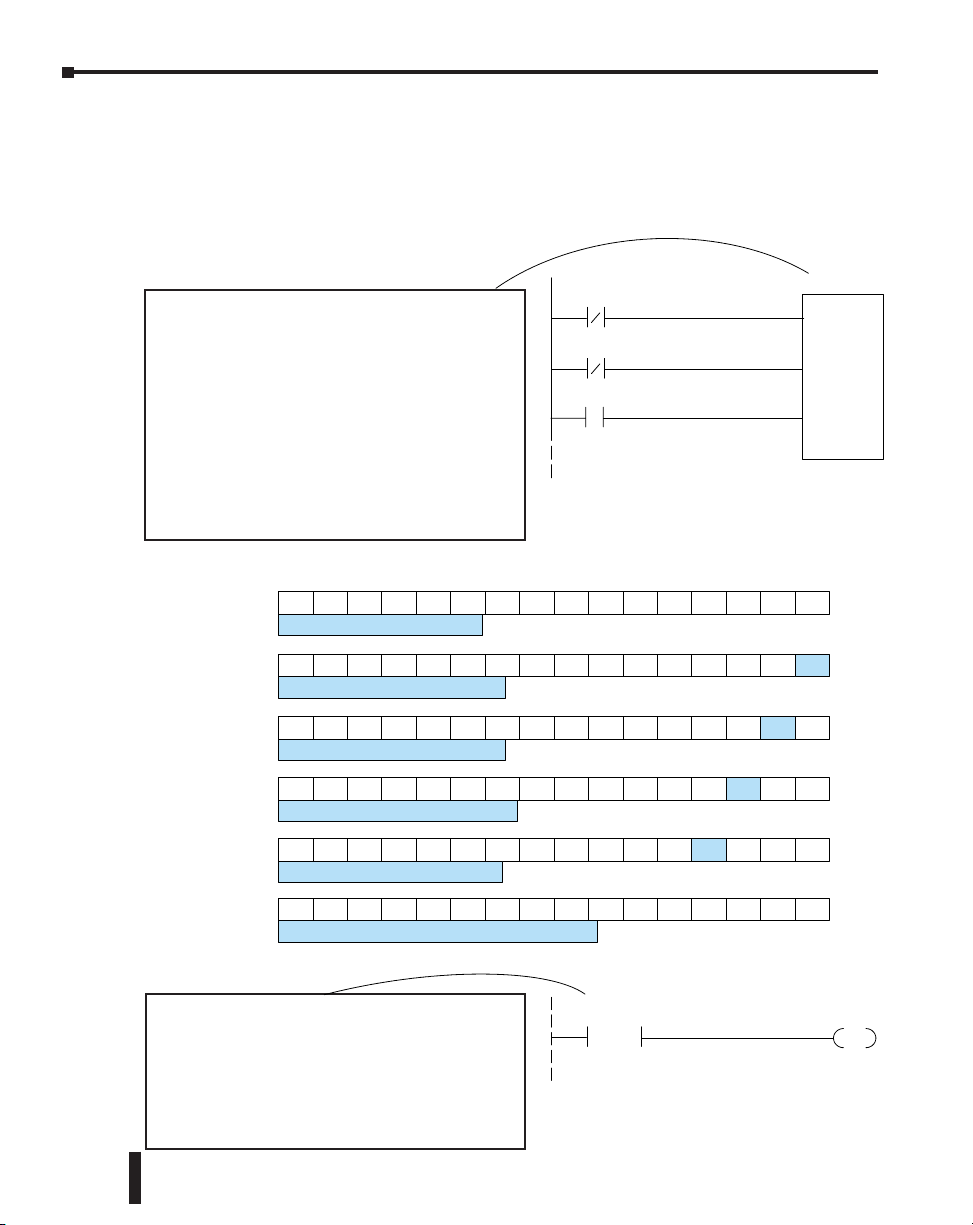
Chapter 4: RLL Programming for Communications
Shift Register
The Shift Register can be used for creating interlocks, as an alternative to using control relays.
For a complete explanation of the function of the Shift Register, see the User Manual for
your PLC. If you have more than a few RX/WX instructions, using control relays can become
cumbersome. The Shift Register allows a single contact to be used in each communication rung
as an interlock.
The data input to the Shift Register (SR) is
Special Relay SP1. SP1 is the always-on bit.
Combined with a normally closed contact it
sends zeros to the Shift Register data input.
The clock input to the Shift Register is SP122,
the communication busy bit. Each time one
of the RX/WX instructions executes, the Shift
Register moves the set bit over one place.
C63 is used in this example to reset the Shift
Register to all zeros.
C74C73 C72C71 C70C67 C66C65 C64C63 C62C61 C60C75C76C77
ShiftRegisterafter first scan.
C74C73 C72C71 C70C67 C66C65 C64C63 C62C61 C60C75C76C77
ShiftRegister aftersecond scan.
C74C73 C72C71 C70C67 C66C65 C64C63 C62C61 C60C75C76C77
ShiftRegister after firstRX/WX.
C74C73 C72C71 C70C67 C66C65 C64C63 C62C61 C60C75C76C77
ShiftRegisterafter second RX/WX.
C74C73 C72C71 C70C67 C66C65 C64C63 C62C61 C60C75C76C77
ShiftRegister after thirdRX/WX.
SP1
SP122
C63
SR
C60
C77
4–20
ShiftRegister afterthird RX/WXplus one scan.
C74C73 C72C71 C70C67 C66C65 C64C63 C62C61 C60C75C76C77
Store If Equal
The Store If Equal instruction detects when
the Shift Register is reset to zeros. When
that condition is true the C60 bit is SET by
this rung. The C60 bit becomes the high bit
shifted by the Shift Register until each RX/WX
instruction is executed in turn.
Ethernet Communications Modules, 3rd Edition, Rev. E
V40603
K0
=
C60
SET
Page 68

First RX/WX Instruction
Chapter 4: RLL Programming for Communications
C60 is the interlocking contact. It is
turned on by the Store If Equal rung
preceding this one.
Second RX/WX Instruction
C61 is the interlocking contact. It is
turned on by the sequencing steps of
the Shift Register in a preceding rung.
SP122
SP122
C60
C61
LD
K114
LD
K2
LDA
O40600
WX
VC100
LD
K109
LD
K2
LDA
O40601
WX
VC0
Third RX/WX Instruction
C62 is the interlocking contact. It is
SP122
turned on by the sequencing steps
of the Shift Register in a preceding
rung.
After this rung is executed, the Shift Register shifts the high bit from C62 to C63 on the next
CPU scan. C63 resets the Shift Register to zeros, the Store If Equal sets the C60 bit, and the
CPU executes the first RX/WX instruction.
Ethernet Communications Modules, 3rd Edition, Rev. E
C62
LD
K114
LD
K2
LDA
O40602
RX
VC20
4–21
Page 69

Chapter
Chapter
MODBUS TCP fOr
H0/H2/H4-ECOM100
In This Chapter...
Modbus TCP .............................................................................................................. 5-2
Supported Modbus Function Codes ......................................................................... 5-4
Network Server (Slave) Operation ............................................................................ 5-5
Network Client (Master) Operation ....................................................................... 5-15
H0/H2/H4 -ECOM100 System Memory .................................................................. 5-22
Chapter
5
5
5
Page 70

Chapter 5: MODBUS TCP for H0/H2/H4-ECOM100
Modbus TCP
Modbus TCP is essentially the serial Modbus RTU protocol encapsulated in a TCP/IP wrapper.
Modbus RTU is used for serial communications between a master and slave(s) devices. Modbus
TCP is used for TCP/IP communications between client and server devices on an Ethernet
network. The TCP version of Modbus follows the OSI Network Reference Model.
NOTE: You must configure the peer to peer configuration as shown in Chapter 3 (page 3-10) to use Modbus
TC/P. If the peer to peer configuration is not configured the ECOM100 will use Host Protocol instead of
Modbus TC/P.
Client / Server Model
The Modbus messaging service provides a Client/Server communication between devices
connected on an Ethernet TCP/IP network. This client / server model is based on four types of
messages:
• Modbus Request - the message sent on the network by the Client to initiate a transaction
• Modbus Confirmation - the Response Message received on the Client side
• Modbus Indication - the Request message received on the Server side
• Modbus Response - the Response message sent by the Server
Client / Server Model
Request Indication
Client Server
Confirmation Response
The H0/H2/H4 - ECOM100 can
act as a Client or Server
5-2
Protocol Description
A typical Modbus TCP frame consists of the following fields:
TCP HEADER MBAP HEADER FUNCTION DATA
The MBAP header (Modbus Application Protocol header) is seven bytes long. It consists of the
following fields.
• Transaction Identifier - It is used for transaction pairing, the Modbus server
copies in the response the transaction identifier of the request. (2 bytes)
• Protocol Identifier - It is used for intra- system multiplexing. The
Modbus protocol is identified by the value 0. (2 bytes)
• Length - The length field is a byte count of the following fields,
including the Unit Identifier and data fields. (2 bytes)
• Unit Identifier - This field is used for intra- system routing purpose. It is
typically used to communicate to a Modbus or a Modbus+ serial line slave
through a gateway between an Ethernet TCP/IP network and a Modbus
serial line. This field is set by the Modbus Client in the request and must be
returned with the same value in the response by the server. (1 byte)
Ethernet Communications Modules, 3rd Edition, Rev. E
Page 71

Chapter 5: MODBUS TCP for H0/H2/H4-ECOM100
This header provides some differences compared to the Modbus RTU application data unit
used on serial line:
• The Modbus “slave address” field usually used on Modbus Serial Line is replaced
by a single byte “Unit Identifier” within the MBAP Header. The “Unit Identifier”
is used to communicate via devices such as bridges, routers and gateways that
use a single IP address to support multiple independent Modbus end units.
• All Modbus requests and responses are designed in such a way that the recipient can
verify that a message is finished. For function codes where the Modbus PDU has a
fixed length, the function code alone is sufficient. For function codes carrying a variable
amount of data in the request or response, the data field includes a byte count.
• Protocol Identifier - It is used for intra- system multiplexing. The
Modbus protocol is identified by the value 0. (2 bytes)
The function code field of a message contains 8 bits. Valid function codes are in the range of 1
- 255 decimal. The function code instructs the slave what kind of action to take. Some examples
are to read the status of a group of discrete inputs; to read the data in a group of registers; to
write to an output coil or a group of registers; or to read the diagnostic status of a slave.
When a slave responds to the master, it uses the function code field to indicate either a normal
response or that some type of error has occurred. For a normal response, the slave echoes the
original function code. In an error condition, the slave echoes the original function code with
its MSB set to a logic 1.
The data field is constructed using sets of two hexadecimal digits in the range of 00 to FF.
According to the network’s serial transmission mode, these digits can be made of a pair of
ASCII characters or from one RTU character.
The data field also contains additional information that the slave uses to execute the action
defined by the function code. This can include internal addresses, quantity of items to be
handled, etc.
The data field of a response from a slave to a master contains the data requested if no error
occurs. If an error occurs, the field contains an exception code that the master uses to determine
the next action to be taken. The data field can be nonexistent in certain types of messages.
Ethernet Communications Modules, 3rd Edition, Rev. E
5-3
Page 72

Chapter 5: MODBUS TCP for H0/H2/H4-ECOM100
NOTE: ModScan32 is a Windows based application program that can be used as a Modbus master to
access and change data points in a connected device (H0/H2/H4- ECOM100) The utility is ideally suited for
quick and easy testing of Modbus TCP network slave devices. Visit www.win- tech.com to download a free
ModScan32 trial demo and for more information on ModScan32.
Supported Modbu Function Codes
The following Modbus function codes are supported by the H0/H2/H4- ECOM100. Not all
function codes are supported when the ECOM100 serves as a network client. The “Network
Client Operation” section later in this chapter lists the function codes that are supported in
client mode.
Modbus
Function Code
01 Read Discrete Output Table
02 Read Discrete Input Table
03
04
05 Force Single Discrete Output
08 Loop Back / Maintenance
15 Force Multiple Discrete Outputs
16 Preset Multiple Holding Registers
Read Holding registers (when addressing mode
is 584/984, this function is used to access
analog output registers)
Read Input Registers (when addressing mode is
584/984, this function is used to access analog
input registers)
Function
Server
Mode
Yes
Client
Mode
Yes
No06 Preset Single Holding Registers
Yes
5-4
Ethernet Communications Modules, 3rd Edition, Rev. E
Page 73

Chapter 5: MODBUS TCP for H0/H2/H4-ECOM100
Network Server (Slave) Operation
This section describes how other Modbus TCP clients on a network can communicate with an
H0/H2/H4 -ECOM100 that you have configured for Modbus TCP protocol. A network client
must send a Modbus function code and Modbus address to specify a PLC memory location
the DL05/06/205/405 CPU. No CPU ladder logic is required to support Modbus TCP server
operation.
Modbus Function Codes Supported
The H0/H2/H4 -ECOM100 supports the following Modbus function codes when acting as a
Modbus TCP server.
Modbus
Function Code
01 Read Discrete Output Table Y, C, T, CT
02 Read Discrete Input Table X, SP
03
04
05 Force Single Discrete Output Y, C, T, CT
06 Preset Single Holding Registers V
08 Loop Back / Maintenance
15 Force Multiple Discrete Outputs Y, C, T, CT
16 Preset Multiple Holding Registers
Read Holding registers (when addressing mode
is 584/984, this function is used to access
analog output registers)
Read Input Registers (when addressing mode is
584/984, this function is used to access analog
input registers)
Function
DL05/06/205/405
Data Types Available
V
V
V
Determining the Modbus Address
There are typically two ways that most Modbus addressing conventions allow you to specify a
PLC memory location. These are:
• By specifying the Modbus data type and address
• By specifying a Modbus address only.
Ethernet Communications Modules, 3rd Edition, Rev. E
5-5
Page 74

Chapter 5: MODBUS TCP for H0/H2/H4-ECOM100
If Your Host Software or Client Requires the Data Type and Address
Many Modbus TCP clients allow you to specify the Modbus data type and the Modbus address
that corresponds to the PLC memory location. This is the easiest method, but not all packages
allow you to do it this way.
The actual equation used to calculate the address depends on the type of PLC data you are using.
The PLC memory types are split into two categories for this purpose.
• Discrete – X, SP, Y, C, S, T(contacts), CT (contacts)
• Word – V-Memory, Timer current value, Counter current value
In either case, you basically convert the PLC octal address to decimal and add the appropriate
Modbus starting address (as required). The following tables show the exact range used for each
group of data.
NOTE: For an automated Modbus/Koyo address conversion utility, download the file
Modbus_conversion.xls from the www.automationdirect.com technical support website.
DL05 Memory Type
For Discrete Data Types... Convert PLC Addr. to Dec. + Start of Range
Inputs (X)
Special Relays (SP)
Outputs (Y)
Control Relays (C)
Timer Contacts (T)
Counter Contacts (CT)
Stage Status Bits (S)
For Word Data Types ... Convert PLC Addr. to Dec. + Data Type
Timer Current Values (V)
Counter Current Values (V)
V-Memory, user data (V)
Qty
(Dec.)
256 X0 – X377 2048 – 2303
512 SP0 – SP777 3072 – 3583 Input
256 Y0 – Y377 2048 – 2303 Coil
512 C0 –C777 3072 – 3583 Coil
128 T0 – T177 6144 – 6271 Coil
128 CT0 – CT177 6400 – 6527 Coil
256 S0 – S377 5120 – 5375 Coil
128 V0 – V177 0 – 127
128 V1000 – V1177 512 – 639 Input Register
3072 V1400 – V7377 768 – 3839
PLC Range
(Octal)
Modbus
Address Range
Input Register
Holding Register
Modbus
Data Type
+ Data Type
Input
5-6
Ethernet Communications Modules, 3rd Edition, Rev. E
Page 75

Chapter 5: MODBUS TCP for H0/H2/H4-ECOM100
DL06 Memory Type
For Discrete Data Types... Convert PLC Addr. to Dec. + Start of Range
Inputs (X)
Special Relays (SP)
Outputs (Y)
Control Relays (C)
Timer Contacts (T)
Counter Contacts (CT)
Stage Status Bits (S)
Global Inputs (GX)
Global Outputs (GY)
For Word Data Types ... Convert PLC Addr. to Dec. + Data Type
Timer Current Values (V)
Counter Current Values (V)
V-Memory, user data (V)
D2-240 Memory Type
For Discrete Data Types... Convert PLC Addr. to Dec. + Start of Range
Inputs (X)
Special Relays (SP)
Outputs (Y)
Control Relays (C)
Timer Contacts (T)
Counter Contacts (CT)
Stage Status Bits (S)
For Word Data Types ... Convert PLC Addr. to Dec. + Data Type
Timer Current Values (V)
Counter Current Values (V)
V-Memory, user data (V)
V-Memory, user data (V)
non-volatile
V-Memory, system (V)
Qty
(Dec.)
512 X0 – X777 2048 – 2559
512 SP0 – SP777 3072 – 3583 Input
512 Y0 – Y777 2048 – 2559 Coil
1024 C0 –C1777 3072 – 4095 Coil
256 T0 – T377 6144 – 6399 Coil
128 CT0 – CT177 6400 – 6527 Coil
1024 S0 – S1777 5120 – 6143 Coil
2048 GX0 – GX3777 0 – 2047 Input
2048 GY0 – GY3777 0 – 2047 Coil
128 V0 – V177 0 – 127
128 V1000 – V1177 512 – 639 Input Register
256
3072
4096
Qty
(Dec.)
320 X0 – X477 2048 – 2559
144
320 Y0 – Y477 2048 – 2367 Coil
256 C0 –C377 3072 – 3551 Coil
128 T0 – T177 6144 – 6271 Coil
128 CT0 – CT177 6400 – 6527 Coil
512 S0 – S777 5120 – 5631 Coil
128 V0 – V177 0 – 127
128 V1000 – V1177 512 – 639 Input Register
1024 V2000 – V3777 1024 – 2047 Holding Register
256 V4000 – V4377 2048 – 2303 Holding Register
106
PLC Range
(Octal)
V400 – V677
V1400 – V7377
V10000 – V17777
PLC Range
(Octal)
SP0 – SP137
SP540 – SP617
V7620 – V7737
V7746 – V7777
Modbus
Address Range
256 – 511
768 – 3839
4096 – 8191
Modbus
Address Range
3072 – 3167
3280 – 3471
V3984 – V4063
V4070 – V4095
Input Register
Holding Register
Input Register
Holding Register
Modbus
Data Type
+ Data Type
Input
Modbus
Data Type
+ Data Type
Input
Input
Ethernet Communications Modules, 3rd Edition, Rev. E
5-7
Page 76

Chapter 5: MODBUS TCP for H0/H2/H4-ECOM100
D2-250-1 Memory Type
For Discrete Data Types... Convert PLC Addr. to Dec. + Start of Range
Inputs (X)
Special Relays (SP)
Outputs (Y)
Control Relays (C)
Timer Contacts (T)
Counter Contacts (CT)
Stage Status Bits (S)
For Word Data Types ... Convert PLC Addr. to Dec. + Data Type
Timer Current Values (V)
Counter Current Values (V)
V-Memory, user data (V)
V-Memory, system (V)
D2-260/D2-262
Memory Type
For Discrete Data Types... Convert PLC Addr. to Dec. + Start of Range
Inputs (X)
Special Relays (SP)
Outputs (Y)
Control Relays (C)
Timer Contacts (T)
Counter Contacts (CT)
Stage Status Bits (S)
Global Inputs (GX)
Global Outputs (GY)
For Word Data Types ... Convert PLC Addr. to Dec. + Data Type
Timer Current Values (V)
Counter Current Values (V)
V-Memory, user data (V)
V-Memory, system (V)
Qty
(Dec.)
512 X0 – X777 2048 – 2560
512
512 Y0 – Y777 2048 – 2560 Coil
1024 C0 –C1777 3072 – 4095 Coil
256 T0 – T377 6144 – 6399 Coil
128 CT0 – CT177 6400 – 6527 Coil
1024 S0 – S1777 5120 – 6143 Coil
256 V0 – V377 0 – 255
128 V1000 – V1177 512 – 639 Input Register
3072
4096
256 V7400 – V7777 3840 – 4095
Qty
(Dec.)
1024 X0 – X777 2048 – 3071
512
1024 Y0 – Y1777 2048 – 3071 Coil
2048 C0 –C3777 3072 – 5119 Coil
256 T0 – T377 6144 – 6399 Coil
256 CT0 – CT377 6400 – 6655 Coil
1024 S0 – S1777 5120 – 6143 Coil
2048 GX0 – GX3777 0 – 2047 Input
2048 GY0 – GY3777 0 – 2047 Coil
256 V0 – V377 0 – 255
256 V1000 – V1377 512 – 639 Input Register
256
3072
11264
256
PLC Range
(Octal)
SP0 – SP137
SP320 – SP777
V1400 – V7377
V10000 – V17777
PLC Range
(Octal)
SP0 – SP137
SP320 – SP717
V400 – V777
V1400 – V7377
V10000 – V35777
V7600 – V7777
V36000 – V37777
Modbus
Address Range
3072 – 3167
3280 – 3583
768 – 3839
4096 – 8191
Modbus
Address Range
3072 – 3167
3280 – 3535
256 – 511
768 – 3839
4096 – 15359
3968 – 4095
15360 – 16383
Holding Register
Holding Register
Holding Register
Holding Register
Modbus
Data Type
+ Data Type
Input
Input
Input Register
Modbus
Data Type
+ Data Type
Input
Input
Input Register
5-8
Ethernet Communications Modules, 3rd Edition, Rev. E
Page 77

Chapter 5: MODBUS TCP for H0/H2/H4-ECOM100
D4-430
Memory Type
For Discrete Data Types... Convert PLC Addr. to Dec. + Start of Range
Inputs (X)
Special Relays (SP)
Outputs (Y)
Control Relays (CR)
Timer Contacts (T)
Counter Contacts (CT)
Stage Status Bits (S)
Global I/O (GX)
For Word Data Types ... Convert PLC Addr. to Dec. + Data Type
Timer Current Values (V)
Counter Current Values (V)
V-Memory, user data (V)
V-Memory, system (V)
D4-440
Memory Type
For Discrete Data Types... Convert PLC Addr. to Dec. + Start of Range
Inputs (X)
Special Relays (SP)
Outputs (Y)
Control Relays (CR)
Timer Contacts (T)
Counter Contacts (CT)
Stage Status Bits (S)
Global I/O (GX)
For Word Data Types ... Convert PLC Addr. to Dec. + Data Type
Timer Current Values (V)
Counter Current Values (V)
V-Memory, user data (V)
V-Memory, system (V)
Qty
(Dec.)
320 X0 – X477 2048 – 3071
288
320 Y0 – Y477 2048 – 2367 Coil
512 C0 –C737 3072 – 3583 Coil
128 T0 – T177 6144 – 6271 Coil
128 CT0 – CT177 6400 – 6527 Coil
384 S0 – S577 5120 – 5503 Coil
512 GX0 – GX777 0 – 2047 Input
128 V0 – V377 0 – 255
128 V1000 – V1377 512 – 639 Input Register
3072 V1400 – V7377 768 – 3839 Holding Register
256 V7400 – V7777 3840 – 4095
Qty
(Dec.)
320 X0 – X477 2048 – 2367
352
320 Y0 – Y477 2048 – 2367 Coil
1024 C0 –C1777 3072 – 4095 Coil
256 T0 – T377 6144 – 6399 Coil
128 CT0 – CT177 6400 – 6527 Coil
1024 S0 – S1777 5120 – 6143 Coil
1024 GX0 – GX1777 0 – 1023 Input
256 V0 – V377 0 – 255
128 V1000 – V1377 512 – 639 Input Register
3072
4096
268
PLC Range
(Octal)
SP0 – SP137
SP320 – SP617
PLC Range
(Octal)
SP0 – SP137
SP320 – SP717
V1400 – V7377
V10000 – V17777
V700 – V737
V7400 – V7777
Modbus
Address Range
(Decimal)
3072 – 3167
3280 – 3471
Modbus
Address Range
(Decimal)
3072 – 3167
3280 – 3535
768 – 3839
4096 – 8191
448 – 479
3840 – 4095
Input Register
Holding Register
Input Register
Holding Register
Holding Register
Modbus
Data Type
+ Data Type
Input
Input
Modbus
Data Type
+ Data Type
Input
Input
Ethernet Communications Modules, 3rd Edition, Rev. E
5-9
Page 78

Chapter 5: MODBUS TCP for H0/H2/H4-ECOM100
D4-450/D4-454
Memory Type
For Discrete Data Types... Convert PLC Addr. to Dec. + Start of Range
Inputs (X)
Special Relays (SP)
Outputs (Y)
Control Relays (C)
Timer Contacts (T)
Counter Contacts (CT)
Stage Status Bits (S)
Global Inputs (GX)
Global Outputs (GY)
For Word Data Types ... Convert PLC Addr. to Dec. + Data Type
Timer Current Values (V)
Counter Current Values (V)
V-Memory, user data (V)
V-Memory, system (V)
Qty
(Dec.)
1024 X0 – X777 2048 – 3071
512
1024 Y0 – Y1777 2048 – 3071 Coil
2048 C0 –C3777 3072 – 5119 Coil
256 T0 – T377 6144 – 6399 Coil
256 CT0 – CT377 6400 – 6655 Coil
1024 S0 – S1777 5120 – 6143 Coil
1536 GX0 – GX2777 0 – 1535 Input
1536 GY0 – GY2777 0 – 1535 Coil
256 V0 – V377 0 – 255
256 V1000 – V1377 512 – 767 Input Register
3072
12288
320
PLC Range
(Octal)
SP0 – SP137
SP320 – SP717
V1400 – V7377
V10000 – V37777
V700 – V777
V7400 – V7777
Modbus
Address Range
3072 – 3167
3280 – 3535
768 – 3839
4096 – 16383
448 – 768
3968 – 4095
Holding Register
Holding Register
Modbus
Data Type
+ Data Type
Input
Input
Input Register
5-10
Ethernet Communications Modules, 3rd Edition, Rev. E
Page 79

Chapter 5: MODBUS TCP for H0/H2/H4-ECOM100
The following examples show how to generate the Modbus address and data type for hosts
which require this format.
Example 1: V2100
Find the Modbus address for User V location V2100.
1. Find V- Memory in the table.
2. Convert V2100 into decimal (1088).
3. Use the Modbus data type from the table.
PLC Addr. (Dec.) + Data Type
V2100 = 1088 decimal
1088 + Hold. Reg. =
Holding Reg.
Timer Current Values (V)
Counter Current Values (V)
V-Memory, user data (V)
128 V0 – V177 0 – 127
128 V1000 – V1177 512 – 639 Input Register
1024 V2000 – V3777 1024 – 2047
Example 2: Y20
Find the Modbus address for output Y20.
1. Find Y outputs in the table.
2. Convert Y20 into decimal (16).
3. Add the starting address for the range (2049).
4. Use the Modbus data type from the table.
Outputs (Y)
Control Relays (C)
320 Y0 – Y477 2049 – 2367
256 C0 –C377 3072 – 3551
Example 3: T10 Current Value
Find the Modbus address to obtain the current value
from Timer T10.
1. Find Timer Current Values in the table.
2. Convert T10 into decimal (8).
3. Use the Modbus data type from the table.
Timer Current Values (V)
Counter Current Values (V)
128 V0 – V177 0 – 127
128 V1000 – V1177 512 – 639
Input Register
Holding Register
PLC Addr.(Dec.) + Start Addr. + Data Type
Y20 = 16 decimal
16 + 2049 + Coil =
Coil 2065
Coil
Coil
PLC Addr.(Dec.) + Data Type
T10 = 8 decimal
8 + Input Reg. =
Input Reg. 8
Input Register
Input Register
Ethernet Communications Modules, 3rd Edition, Rev. E
5-11
Page 80

Chapter 5: MODBUS TCP for H0/H2/H4-ECOM100
Example 4: C54
Find the Modbus address for Control Relay C54
1. Find Control Relays in the table.
2. Convert C54 into decimal (44).
3. Add the starting address for the range (3072).
4. Use the Modbus data type from the table.
Outputs (Y)
Control Relays (CR)
320 Y0 – Y477 2049 – 2367
256 C0 –C377 3072 – 3551
PLC Addr.(Dec.) + Start Addr. + Data
If the Host Software or Client Requires an Address ONLY
Some Modbus TCP clients do not allow you to specify the Modbus data type and address.
Instead, you specify an address only. This method requires another step to determine the
address, but it is not difficult. Basically, Modbus also separates the data types by address ranges
as well. This means an address alone can actually describe the type of data and location. This is
often referred to as “adding the offset”.
The actual equation used to calculate the address depends on the type of PLC data you are
using. The PLC memory types are split into two categories for this purpose.
• Discrete – X, GX, SP, Y, CR, S, T, C (contacts)
• Word – V-memory , Timer current value, Counter current value
In either case, you basically convert the PLC octal address to decimal and add the appropriate
Modbus starting address (as required). The following tables show the exact range used for each
group of data.
C54= 44 decimal
44 + 3072 + Coil =
Coil 3117
Coil
Coil
5-12
NOTE: For an automated Modbus/Koyo address conversion utility, download the file
Modbus_conversion.xls from the www.automationdirect.com website.
Discrete Data Types*
PLC Memory Type
Global Inputs (GX)
Inputs (X)
Special Relays (SP)
Reserved
Global Outputs (GY)
Outputs (Y)
Control Relays (CR)
Timer Contacts (T)
Counter Contacts (CT)
Stage Status Bits (S)
Reserved
* Refer to your PLC user manual for the correct memory mapping size of your PLC. Some of the addresses shown above might not pertain
to your particular CPU.
Qty
(Dec.)
2048
1024 X0 – X1777 2048 – 2367
512 SP0 – SP777 13073 – 13584
– – 13585 – 20000
2048 GY0 – GY3777 0 – 2048
1024 Y0 – Y1777 2049 – 3072
2048 C0 –C3777 3073 – 5012
256 T0 – T377 6145 – 6400
256 CT0 – CT377 6401 – 6656
1024 S0 – S1777 5121 – 6144
–– –– 6657 – 10000
PLC Range
(Octal)
GX0 – GX1746
GX1747 – GX3777
Modbus
Address Range
0 – 1023
Access
Read Only
Read/Write
Ethernet Communications Modules, 3rd Edition, Rev. E
Page 81

Chapter 5: MODBUS TCP for H0/H2/H4-ECOM100
Word Data Types*
Registers (Word)
(V-Memory)
Timers
Counters
Data Words
System Parameters
Remote Inputs
Remote Outputs
Input Points
Output Points
Control Relays
Timer Status Bits
Counter Status Bits
Special Relays
* Refer to your PLC user manual for the correct memory mapping size of your PLC. Some of the addresses shown above might not pertain to your particular CPU.
Qty
(Dec.)
256 V0 – V377 40001 – 40256 30001 – 30256
256 V1000 – V1377 40513 – 40768 30513 – 30768
256 V400 – V777 40257 – 40512 30257 – 30512
3072 V1400 – V7377 40769 – 43840 30769 – 33840
5906 V10000 – V23416 44097 – 49999 34097 – 39999
5361 V23417 – V35777 410000 – 415360 310000 – 315360
128
1024
128 V40000 – V40177 416385 – 416512 316385 – 316512 Read Only
128 V40200 – V40377 416513 – 416640 316513 – 316640 Read/Write
64 V40400 – V40477 416641 – 416704 316641 – 316704 Read Only
64 V40500 – V40577 416705 – 416768 316705 – 316768
128 V40600 – V40777 416769 – 416896 316769 – 316896
16 V41100 – V41117 416961 – 416976 316961 – 316976
16 V41140 – V41157 416993 – 417008 316993 – 317008
32 V41200 – V41237 417025 – 417056 317025 – 317056
PLC Range
(Octal)
V7600 – V7777
V36000 – V37777
Modbus 40001
Address Range
43969 – 44096
415361 – 416384
Modbus 30001
Address Range
33969 – 34096
315361 – 316384
Access
Read/Write
Read/Write
Read Only
Ethernet Communications Modules, 3rd Edition, Rev. E
5-13
Page 82

Chapter 5: MODBUS TCP for H0/H2/H4-ECOM100
The following examples show how to generate the Modbus address and data type for hosts
which require this format.
Example 1: V2100
Find the Modbus address for User V location V2100.
1. Find V-memory in the table.
2. Convert V2100 into decimal (1088).
3. Add the Modbus starting address for the mode (40001).
For Word Data Types ... PLC Address Dec. + Appropriate Mode Address
Timer Current Values (V)
Counter Current Values (V)
V-Memory, user data (V)
128 V0 – V177 0 – 127 3001 30001 Input Reg.
128 V1000 – V1177 512 – 639 3001 30001 Input Reg.
1024 V2000 – V3777 1024 – 2047 4001 40001
Example 2: Y20
Find the Modbus address for output Y20.
1. Find Y outputs in the table.
2. Convert Y20 into decimal (16).
3. Add the starting address for the range (2048).
4. Add the Modbus address for the mode (1).
PLC Addr.(Dec.) + Start Address + Mode
PLC Addr. (Dec.) + Mode Address
V2100 = 1088 decimal
1088 + 40001 =
41089
Holding Reg.
Y20 = 16 decimal
16 + 2048 + 1 =
2065
5-14
Outputs (Y)
Control Relays (CR)
Timer Contacts (T)
320 Y0 – Y477 2048 – 2367 1 1
256 C0 –C377 3072 – 3551 1 1 Coil
128 T0 –T177 6144 – 6271 1 1
Example 3: C54
Find the Modbus address for Control Relay
C54.
1. Find Control Relays in the table.
2. Convert C54 into decimal (44).
3. Add the starting address for the range (3072).
4. Add the Modbus address for the mode (1).
Outputs (Y)
Control Relays (CR)
Timer Contacts (T)
Ethernet Communications Modules, 3rd Edition, Rev. E
320 Y0 – Y477 2048 – 2367 1 1
256 C0 –C377 3072 – 3551 1 1 Coil
128 T0 –T177 6144 – 6271 1 1
Coil
Coil
PLC Addr.(Dec.) + Start Address + Mode
C54 = 44 decimal
44 + 3072 + 1 =
3117
Coil
Coil
Page 83

Chapter 5: MODBUS TCP for H0/H2/H4-ECOM100
Network
Network Client (Master) Operation
This section describes how the DL05/06/205/405 CPU can serve as a client on a Modbus TCP
network using the H0/H2/H4 -ECOM100. This section discusses how to design the required
ladder logic for network client operation.
Client
MODBUS TCPServers
Slave #1 Slave#3
MODBUS TCP Protocol
When using the ECOM100 as a client on the
network, you use simple RLL instructions to
initiate the requests. The WX instruction initiates
network write operations, and the RX instruction
initiates network read operations. Before executing
either the WX or RX commands, we need to load
data related to the read or write operation onto the
CPU’s accumulator stack. When the WX or RX
instruction executes, it uses the information on the
stack combined with data in the instruction box to
completely define the task.
Slave#2
Client
Slave
WX (write)
RX (read)
Ethernet Communications Modules, 3rd Edition, Rev. E
5-15
Page 84

Chapter 5: MODBUS TCP for H0/H2/H4-ECOM100
Modbus Function Codes Supported
The H0/H2/H4 -ECOM100 supports the following Modbus function codes when acting as a
Modbus TCP client.
ECOM100 as Modbus TCP Client
PLC
Instruction
RX
WX
Operand
GY0 – GY3777
Y0 – Y1777 2049 – 3072
C0 –C3777 3073 – 5120
S0 – S1777 5121 – 6144
T0 –T377 6144 – 6400
CT0 – CT377 6401 – 6656
GX0 – GX3777
SP0 – SP777 3073 – 3584
V0 – V41117
V41200 – V41237 17025 – 17056
GY0 – GY3777
Y0 – Y1777 2049 – 3072
C0 –C3777 3073 – 5120
S0 – S1777 5121 – 6144
T0 –T377 6145 – 6400
CT0 – CT377 6401 – 6656
GX0 – GX3777
SP0 – SP777 3073 – 3584
V0 – V41117
V41200 – V41237 17025 – 17056
V0 – V41117 (odd length)
V41200 – V41237 (odd length) 17025 – 17056
Base Offset
00000
10000
40000
00000
10000
40000
30000
Modbus
1 – 16976
1 – 16976
1 – 16976
1 – 2048
1 – 2048
1 – 2048
1 – 2048
FC Description
01
02 Read InputsX0 – X1777 2049 – 3072
03 Read Holding RegistersV41140 – V41157 16993 – 17008
15 Force Multiple Coils
– –X0 – X1777 2049 – 3072
16 Preset Multiple RegistersV41140 – V41157 16993 – 17008
– –V41140 – V41157 (odd length) 16993 – 17008
Read Coils
5-16
NOTE: The H0/H2/H4- ECOM100, as a client/master, supports function code 4. Thus, 30001 address
ranges can be read from a server/slave device.
This is done by specifying an odd number of bytes transfered instead of the normal even number of bytes.
Thus: Even number of bytes to transfer: RX/WX for the Holding Registers (400001+ address range).
Odd number of bytes to transfer: RX for the Input Registers (30001+ address range). It is not possible to
use WX on 30001 address ranges because by definition Input Registers are "read-only."
Ethernet Communications Modules, 3rd Edition, Rev. E
Page 85

Chapter 5: MODBUS TCP for H0/H2/H4-ECOM100
PLC Memory Supported for Client Operation
The actual equation used to calculate the address depends on the type of PLC data you are
using. The PLC memory types are split into three categories for this purpose.
• Discrete Inputs - GX, X, SP
• Discrete Outputs - GY, Y, CR, T, CT, S
• Word - Timer current value, Counter current value, Data Words
In either case, you basically take the Modbus address you are trying to target, subtract the
starting Modbus of that range, convert the result to octal and add the octal number to the
begining PLC address in the appropriate PLC range. See the conversion examples on the
following page. The following tables show the exact range used for each group of data.
NOTE: For an automated Modbus/Koyo address conversion utility, download the file
Modbus_conversion.xls from the www.automationdirect.com website.
Discrete Data Types*
PLC Memory Type
Global Inputs (GX)
Inputs (X)
Special Relays (SP)
Reserved
Global Outputs (GY)
Outputs (Y)
Control Relays (CR)
Timer Contacts (T)
Counter Contacts (CT)
Stage Status Bits (S)
Reserved
Qty
(Dec.)
2048
1024 X0 – X1777 12049 – 13072
512 SP0 – SP777 13073 – 13584
– – 13585 – 20000
2048 GY0 – GY3777 1 – 2048
1024 Y0 – Y1777 2049 – 3072
2048 C0 –C3777 3073 – 5120
256 T0 – T377 6145 – 6400
256 CT0 – CT377 6401 – 6656
1024 S0 – S1777 5121 – 6144
–– –– 6657 – 10000
PLC Range
(Octal)
GX0 – GX1746
GX1747 – GX3777
Modbus
Address Range
10001 – 10999
11000 – 12048
Access
Read Only
Read/Write
Word Data Types*
Registers (Word)
(V-Memory)
Timers
Counters
Data Words
System Parameters
* Refer to your PLC user manual for the correct memory mapping size of your PLC. Some of the addresses shown above might not
pertain to your particular CPU.
Qty
(Dec.)
256 V0 – V377 40001 – 40256
256 V1000 – V1377 40513 – 40768
256 V400 – V777 40257 – 40512
3072 V1400 – V7377 40769 – 43840
5903 V10000 – V23416 44097 – 49999
5361 V23417 – V35777 410000 – 415360
128
1024
PLC Range
(Octal)
V7600 – V7777
V36000 – V37777
Modbus
Address Range
43969 – 44096
415361 – 416384
Access
Read/Write
Ethernet Communications Modules, 3rd Edition, Rev. E
5-17
Page 86

Chapter 5: MODBUS TCP for H0/H2/H4-ECOM100
NOTE: Your PC’s Windows calculator can be used for number conversions (i.e. decimal to octal). The
Windows calculator must be in Calculator>View>Scientific mode to enable number conversions capability.
Example 1: Calculating Word PLC Address
Find the PLC address to use to target Modbus
address 41025 in a server device.
1. Subtract the beginning of the Modbus word
address range (40001) from the desired
Modbus address to target.
2. Convert decimal result into octal.
3. Add octal result to beginning PLC range
(Input, Output or Word).
Example 2: Calculating Discrete Input PLC Address
Find the PLC address to use to target Modbus
address 12060 in a server device.
1. Subtract the beginning of the Modbus Input
address range (12049) from the desired
Modbus address to target.
2. Convert decimal result into octal.
3. Add octal result to beginning PLC range
(Input, Output or Word).
1. 41025 - 40001 = 1024 decimal
2. 1024 decimal = 2000 octal
3. V0 (octal) + 2000 (octal) = V2000 octal
1. 12060 - 12049 = 11 decimal
2. 11 decimal = 13 octal
3. X0 (octal) + 13 octal = X13 octal
5-18
Ethernet Communications Modules, 3rd Edition, Rev. E
Page 87

Chapter 5: MODBUS TCP for H0/H2/H4-ECOM100
Building the Read (RX) or Write (WX) Routine
For network communications, you build the Read (RX) or
Write (WX) instructions into a routine which requires the
four instructions you see to the right. They must be used in
the sequence shown. The following step-by-step procedure
will provide you the information necessary to set up your
ladder program to receive data from a network server.
NOTE: Please review intelligent instructions (IBOX) in Chapter 5 of the user manual for the PLC you are
using, which simplifies this and other functions.
Consider the following IBOX instructions: ECOM100, ECRX and ECWX.
LD
Aaaa
LD
Aaaa
LDA
Oaaa
RX or WX
Aaaa
Step 1: Identify ECOM Slot Location and Server Node #
The first Load (LD) instruction accepts either a constant or a variable. Use a “K” to designate
the number as a constant. Use a “V” if you are entering the address of a register. The contents
of that register perform the same function as the constant shown below. For example, you could
use V2000 in place of K0114. If the contents of V2000 is the number “114,” the function
would be the same. Using a variable allows changing parameters while the program is running.
InitiatingPLC/ECOM
(Client)
Base Number
CPUBase=0
ExpansionBase=1, 2or3
Seepage 2-7 and2-- 9about usingECOMs in localexpansion or
in remoteI/O bases.
UpperByte
K
Initiating PLC
Seepage2-7 and 2-8 about
slot numbers.
Lower Byte
1140
ECOM Slot Number
Responding
device
(Server)
ServerNode#
Responding Device on Network
Seepage 3--10or6-- 4about
assigning a node number to a
server’sIP address
LD
Ethernet Communications Modules, 3rd Edition, Rev. E
K114
5-19
Page 88

Chapter 5: MODBUS TCP for H0/H2/H4-ECOM100
Step 2: Load Number of Bytes to Transfer
1 2 8
The second Load (LD) instruction determines the
number of bytes which will be transferred between
the master and slave in the subsequent WX or RX
#ofbytes to transfer
instruction. The value to be loaded is in BCD format
(decimal), from 1 to 128 bytes. Requesting an even
number of bytes, generates a Modbus message using
LD
K128
Function 03, Read Holding Registers. If you need
to Read Input Registers, Function Code 04, enter an
4
6 0 00
odd number of bytes. For example, to read 10 Input
Holding Registers, enter 2 (bytes/word) X 10 registers
+ 1, 21 bytes. This will request ten 30001 range
addresses from the Modbus server (slave) device.
Step 3: Specify Master Memory Area
Starting addressof
client transferarea
LDA
O40600
The third instruction in the RX or WX sequence is
a Load Address (LDA) instruction. Its purpose is to
V40600
load the starting address of the memory area to be
transferred. Entered as an octal number, the LDA
instruction converts it to hex and places the result in
V40601
the accumulator.
For a WX instruction, the CPU sends the number
of bytes previously specified from its memory area
beginning at the LDA address specified.
For an RX instruction, the CPU reads the number of bytes previously specified from the
server, placing the received data into its memory area beginning at the LDA address specified.
(BCD)
(octal)
BSLBSM
015
BSLBSM
015
5-20
NOTE: Since V-memory words are always 16 bits, you may not always use the whole word. For example, if
you only specify to read 3 bytes, you will only get 24 bits of data. In this case, only the 8 least significant
bits of the last word location will be modified. The remaining 8 bits are not affected.
Step 4: Specify Slave Memory Area
The last instruction in our sequence is the WX or RX
instruction itself. Use WX to write to the server, and
RX to read from the server. All four of our instructions
are shown to the right. In the last instruction, you must
specify the starting address and a valid data type for the
server.
Ethernet Communications Modules, 3rd Edition, Rev. E
SP122
LD
K114
LD
K128
LDA
O40600
RX
V0
Page 89

Chapter 5: MODBUS TCP for H0/H2/H4-ECOM100
Interlocking Relay
RST
Communications from a Ladder Program
SP123
Typically network communications will last longer than
1 scan. The program must wait for the communications
to finish before starting the next transaction.
ECOM Communication
Error
SP122
ECOM Port Busy
ECOM Port Busy
Depending on which slot the ECOM is in, it has two
Special Relay contacts associated with it (see page 4-11
to 4-12 for special relays). One indicates “Port busy”,
and the other indicates “Port Communication Error”.
The example at right shows the use of these contacts for
an ECOM that is in slot 1. The “Port Busy” bit is on
while the PLC communicates with the slave. When the
bit is off the program can initiate the next network request.
The “Port Communication Error” bit turns on when the PLC has detected an error. Use of this
bit is optional. When used, it should be ahead of any network instruction boxes since it will be
reset when an RX or WX instruction is executed.
Multiple Read and Write Interlocks
If you are using multiple reads and writes in the RLL
program, you have to interlock the routines to make
sure all the routines are executed. If you don’t use the
interlocks, then the CPU will only execute the first
routine. This is because each port can only handle one
transaction at a time.
In the example to the right, after the RX instruction
is executed, C100 is set. When the port has finished
the communication task, the second routine is executed
and C100 is reset.
If your are using RLL
PLUS
Stage Programming, you
can put each routine in a separate program stage to
ensure proper execution and switch from stage to stage
allowing only one of them to be active at a time.
SP122
Interlocking
Relay
SP122
C100
C100
LD
K114
LD
K3
LDA
O40600
RX
V0
LD
K114
LD
K3
LDA
O40600
RX
V0
LD
K114
Y1
SET
C100
SET
Ethernet Communications Modules, 3rd Edition, Rev. E
LD
K3
LDA
O40400
WX
V0
C100
5-21
Page 90

Chapter 5: MODBUS TCP for H0/H2/H4-ECOM100
Network #1 uses the Hx-ECOM100 in Slot 1. This would be the only slot in 05, first slot in
06, and second slot in 205/405 models.
It will use the range of V-memory from V400 - V502 as the working status, workspace and
buffer. These locations must not be used anywhere else.
Make sure Dipswitch 7 is turned ON in the ECOM100.
The Modbus converter spreadsheet from ADC Tech Support site will be extremely useful
to convert Modbus addresses into the octal-based addressing required in the instructions.
NOTE: NetEdit 3 MUST be used to setup the ECOM100 "Peer-to-Peer Config" table in
the ECOM100. This is what determines if the communications are ModbusTCP or ECOM.
ECOM100 IBOX
The following information is an explanation of how to use IBox instructions when using
ECOM100s for Modbus TCP. There are 2 specific IBOX's that can help with Modbus TCP
communications (ECRX and ECWX) and another IBOX (ECOM100) that must be used to
sequence these instructions. Use this information in conjunction with the material covered
earlier in this chapter on Modbus functionality.
The ECOM100 IBOX must be placed at the top of ladder, with no input logic. You will need
one box for each ECOM100 you wish to use. The slot location of the ECOM100 is assigned
to an ECOM # here, as well as the address ranges needed by the instruction. This range MUST
1
ECOM100
ECOM100#
Slot
Status
Workspace
Msg Buffer (65 WORDs)
be unique and cannot be used for any other purpose. The same is true for ANY workspace
V-memory assignment in any IBOX used.
These instructions auto-sequence themselves, but DirectLogic octal addressing still must be
used. There is a Modbus spreadsheet located on our Tech Support site that can be used to
convert the Modbus addresses in the slaves to octal addressing that is required in the ECRX and
ECWX boxes.
Follow this link: http://support.automationdirect.com/docs/modbus_conversion.xls, or
use this application note AN-MISC-010, which is located https://support.automationdirect.
com/technotes.html and select AN-MISC-010 to download the spreadsheet.
Once you have used the spreadsheet to determine the appropriate DL address to use for your
desired Modbus address, place this value into the “From Slave Element” field. Enter the # of
bytes you wish to retrieve, and enter the appropriate DL address you want to receive this data.
The “Slave ID” at this time has no bearing to the actual slave, it will be tied to the IP address of
the Modbus device in the NetEdit and Peer-Peer setup below.
For example, if you want to read the first Modbus coils, you would place “GY1” in “From Slave
Address”, the # of bytes, and you could place the data into C400, for example. For Holding
Registers, you would place the data into V-memory locations. The example program at the
bottom will READ V40001 and V40002 from the Modbus slave, and immediately WRITE
V7766 and V7767 ( RTC Seconds and Minutes) to 40003 and 40004. So if the slave has no
data there, the PLC will send Seconds and Minutes values (except the DL05 which will send 0
unless it has the Real-Time Clock module installed).
ECOM100 Config
ECOM100
V400
V401
V402–V502
K1
K1
5-22
Ethernet Communications Modules, 3rd Edition, Rev. E
Page 91

Chapter 5: MODBUS TCP for H0/H2/H4-ECOM100
For the final steps, you must setup the ECOM100 IP settings and “Peer-Peer” table with
NetEdit3.
In the graphic above, double-click the ECOM100 desired. This will pull up the following
General Settings box. Here, you can assign the IP address and subnet mask for his network.
The Modbus slaves will need to have compatible settings of course. When finished , click OK
to go back to NetEdit main screen.
Ethernet Communications Modules, 3rd Edition, Rev. E
5-23
Page 92

Chapter 5: MODBUS TCP for H0/H2/H4-ECOM100
Modbus TCP Setup
To begin the Modbus TCP setup, highlight the desired ECOM100 module, and select the
“ECOM Settings” tab in lower frame of NetEdit3 window, then click the button marked
“Peer to Peer Config”.
You will get the popup screen seen below:
5-24
To add an entry, click the “Add” button, or “Edit” button to make changes to the existing
settings. Here we will choose “Add”. The Add Device Address popup will open.
Ethernet Communications Modules, 3rd Edition, Rev. E
Page 93

Chapter 5: MODBUS TCP for H0/H2/H4-ECOM100
Make sure to check the box for “ModbusTCP” and
make “Device #” equal to the “Slave ID” that was
used in the ECxX box(s), and enter the IP address
of the Modbus slave. Leave the UnitID at 255 and
port at 502 unless your slave documentation instructs
otherwise.
NOTE: UnitID is normally used with ethernet-serial gateways,
where one IP address (the gateway) may be used for many
serial slaves. Here, the UnitID would represent the serial slave
address, and would need to be changed to match the various
slaves.
So the IP address might be 10.1.45.34 for a Modbus
gateway and the UnitID would be “1” for the first
serial slave,“2” for the second, and so on.
Once you click “OK”, the ECOM100 will be updated, there is no further action to take place
with NetEdit until you are ready to add additional information to the table.
Ethernet Communications Modules, 3rd Edition, Rev. E
5-25
Page 94

Chapter 5: MODBUS TCP for H0/H2/H4-ECOM100
Example Modbus TCP Program
On the following pages is an example RLL program using Device ID 1 from the Peer to Peer
Configuration box. The user could easily add additional IBOXs to implement other devices.
After creating your program, ensure your program has an END statement. Select “Accept”
( F8), and write the project to the PLC (Shift+F9). Make sure after you have written the
project, that the PLC is placed into Program mode, then back into Run mode (many IBOXs
are only processed after a Program-to-Run transition). If everything is correct, V505 ( RX/
WX OK Count) using the Success bit, should be incrementing very fast.
Troubleshooting:
Modbus Addressing: You must know the addressing of your device. Some devices give addresses
in hex values, which can often appear like a decimal value (310 is a valid hex or decimal value).
Asian drives often use hex. You can use Windows calculator “scientific” view to convert the
addresses.
Also, many devices use addresses as “offsets”, particularly Holding Registers. The address
40001 means the first Holding Register, but your device may term this as Holding Register 0
or 1 (the 40000 is assumed). Whether this is actually an address of 0 or 1 is hard to predict.
An excellent method of troubleshooting is to try to only read from the middle of a known
address range, that will have non-zero values. If you know the device has 10 Holding registers
starting at 1, try to read #3, and compare that to the values in the device. If that is one more
or one less than you expect, then that is the offset you will have to use in the DirectLogic
numeric conversion.
• Make sure you can ping your device
• Make sure the PLC has made a Program-to-Run transition
• Make sure the LinkGood light is ON, on the ECOM100 module
• Make sure Dipswitch 7 is ON, on the ECOM100 module
On rare occasions, and almost exclusively with Festo or Numatics devices, their Holding
Registers start at a VERY high number, around 45,000. There isn't an equivalent octal address
to convert that high a value, so a Z constant was introduced that allows the use of a hex
value in the “From Slave Element” field. So a 45,392 address is actually the offset added to
40,000...45,392 = B150 hex, so the entry in the “From Slave Element” field would be ZB150.
There are 3rd party Modbus shareware programs available on the internet, and we have a free
ModbusTCP tester at the link below. You might need to use one of these programs to test to
your device, to make sure they can work successfully to the expected addressing.
http://ftp.automationdirect.com/pub/Modbus_TCP_Master.zip
To read Modbus Input Registers, you must change the number of bytes in any instruction to
the next odd number. For example, if you are reading 16 bytes (8 Registers), then you would
increase the number by 1 to 17 bytes, and the instruction will then be trying to read Modbus
30000 addresses.
5-26
Ethernet Communications Modules, 3rd Edition, Rev. E
Page 95

Chapter 5: MODBUS TCP for H0/H2/H4-ECOM100
Network #1 uses the Hx-ECOM100 in Slot 1. This would be the only slot in 05, first slot in
06, and second slot in 205/405 models.
It will use the range of V-memory from V400 - V502 as the working status, workspace and
buffer. These locations must not be used anywhere else.
Make sure Dipswitch 7 is turned ON in the ECOM100.
The Modbus converter spreadsheet from ADC Tech Support site will be extremely useful
to convert Modbus addresses into the octal-based addressing required in the instructions.
NOTE: NetEdit 3 MUST be used to setup the ECOM100 "Peer-to-Peer Config" table in
the ECOM100. This is what determines if the communications are ModbusTCP or ECOM.
1
On the first PLC scan, set the Comm Success & Comm Error count registers to 0.
Also SETS C106, which is the enable logic to the ECxX boxes.
ECOM100
ECOM100#
Slot
Status
Workspace
Msg Buffer (65 WORDs)
_FirstScan
SPO
2
Once the ECRX and ECWX IBoxes are enabled, the ECOM100 IBox will automatically
sequence them, no manual control of the port busy bits is required.
This example uses C106 with a SET on First Scan, it could be changed to whatever logic
the user desires such as SP1.
ECOM100 Config
LD
OUT
OUT
ECOM100
V402–V502
K0
RX/WX Ok Count
V505
RX/WX Fail Count
V506
C106
SET
V400
V401
K1
K1
3
Ethernet Communications Modules, 3rd Edition, Rev. E
NOP
5-27
Page 96
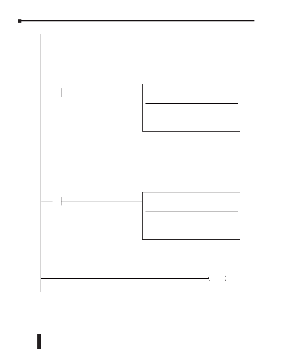
Chapter 5: MODBUS TCP for H0/H2/H4-ECOM100
The ECRX will read from Slave ID "1", and will target address TA0 (V0) which is the
Modbus equvalent address 40001 ( first Holding Register).
It will get 4 bytes ( 2 registers) and place the data in V2000-2001. This data will likely be in
decimal format if coming from 3rd party devices. The DataView window at left has V2000
-2001 set for Decimal format.
Note that Workspace V location must be unique.
C106
4
The ECWX will write to Slave ID "1", and will target address TA2 ( V2) which is the
Modbus equivalent of 40003 ( third Holding Register).
It will write 4 bytes (2 registers) from the PLC addresses V7766-V7767 . These 2
addresses are the Seconds and Minutes from the PLC RealTime Clock, so they are nonzero
most of the time. Note the data will be in BCD/Hex format.
The DL05 will only have data here if using the Option module D0-01MC, otherwise it will
be zeroes.
Note that Workspace location must be unique.
ECRX
ECOM100#
Workspace
Slave ID
From Slave Element (Src)
Number of Bytes
To Master Element (Dest)
Success
Error
C106
5
NOTE: If trying to read Modbus Input Registers ( Function Code 4 or 30001 addressing),
the # of bytes must be increased by 1 to the next odd number. This is how the
DirectLogic and ECOM100 recognize the Modbus address is an Input Register.
ECWX
ECOM100#
Workspace
Slave ID
From Slave Element (Src)
Number of Bytes
To Slave Element (Dest)
Success
Error
ECOM100 RX Network Read
ECOM100 WX Network Write
IB–740
V503
TA 0
V2000
C100
C101
IB–741
V504
V7766
TA 2
C102
C103
K1
K1
K4
K1
K1
K2
5-28
6
Ethernet Communications Modules, 3rd Edition, Rev. E
NOP
Page 97

Chapter 5: MODBUS TCP for H0/H2/H4-ECOM100
The next 2 rungs will count the Success and Errors of the IBOX's. V505 and V506 will
contain the total count of each, respectively.
SP1_ECRX_7_Ok
C100
7
SP1_ECWX_7_Ok
C102
Count failed ECRX and ECWX transactions.
SP1_ECRX_7_Fail
C101
8
SP1_ECWX_7_Fail
C103
9
INCB
RX/WX Ok Count
OUT
RX/WX Fail Count
V505
V506
END
10
Ethernet Communications Modules, 3rd Edition, Rev. E
NOP
5-29
Page 98

Chapter 5: MODBUS TCP for H0/H2/H4-ECOM100
H0/H2/H4 -ECOM100 System Memory
H0/H2/H4 - ECOM100
Modbus
Address Range
(Decimal)
317501 – 317506
Module Version
(417501 – 417506)*
Information
317507 – 317510
(417507 – 417510)
317511 – 317600
Device Data
(417511 – 417600)*
317601 – 318500
(417601 – 418500)
418001 – 418020 20
Dynamic Module Data
418021 – 419250 – Reserved
*For clients that only support function code 3 to read word data.
Words
Word Descriptions Access
(16-bit)
1 - OS Major Version
2 - OS Minor Version
3 - OS Build Version
6
4 - Booter Major Version
5 - Booter Minor Version
6 - Booter Build Version
– Reserved
1 - Version of Device
2 - Family
3 - Processor
4 - Module Type
5 - Status Code
(6 – 8) - Ethernet Address 9 - RAM
Size
10 - Flash Size
11 - Batt RAM Size
90
12 - DIP Settings
13 - Media Type
(14 – 15) - EPF Count (if supported)
16 - Run Relay State (if supported)
17 - Batt Low (if supported)
18 - Model Number
19 - Ethernet Speed
(20 – 90) - Reserved
– Reserved
(1–3) -- Reserved
4 - Flags:
Bit 0: If 1, module has rebooted
since this bit was cleared, a write
to the Flags word with this bit set
will clear this reboot bit.
Bit (1–7) -- Reserved
5 - Reboot Count (LSW) - Read Only
6 - Reboot Count (MSW) - Read Only
(7–20) - Reserved
Read Only
–
Read Only
–
Read/Write
–
5-30
Ethernet Communications Modules, 3rd Edition, Rev. E
Page 99

H0/H2/H4-ECOM100
DHCP & HTML
Chapter
Chapter
Chapter
COnfiguraTiOn
In This Chapter...
H0/H2/H4 -ECOM100 DHCP ..................................................................................... 6-2
Using HTML Configuration ....................................................................................... 6-3
6
6
6
Page 100

Chapter 6: H0/H2/H4-ECOM100 DHCP & HTML Configuration
H0/H2/H4 -ECOM100 DHCP
DHCP Issues
The H0/H2/H4- ECOM100 is configured at the factory to look for a DHCP (Dynamic
Host Configuration Protocol) server at power up. DHCP provides a way to allocate IP address
dynamically to devices on a local area network (LAN). A system or network administrator
configures a DHCP server with a range of IP addresses that can be assigned to DHCP enabled
clients/servers (i.e. H0/H2/H4 -ECOM100).
In addition to an IP address, a DHCP server can provide other information such as DNS
domain or a gateway IP address.
DHCP uses the concept of a “lease” or amount of time that an assigned IP address will be
valid for a client. The lease time can vary depending on how long a user is likely to require the
network connection at a particular location. Since the TCP/IP configuration is “leased” to the
client, that is, it’s not a permanent configuration. This information can change from one power
up session to the next. While this is an acceptable solution for the initial testing and setup of
your H0/H2/H4 -ECOM100 device, we do not recommend that you use DHCP to assign IP
addresses for your runtime operation. Use NetEdit3 or the H0/H2/H4 -ECOM100’s HTML
Configuration page to assign a static IP address to the module (shown below).
NetEdit3 can be used to connect to a H0/H2/H4 -ECOM100 using the IPX protocol, regardless
of the IP address that was assigned to it by a DHCP server.
Disabling DHCP and Assigning a Static IP Address
You can use NetEdit3 or the H0/H2/H4 -ECOM100’s HTML Configuration page to disable
DHCP and assign a static IP address to the module. Click on the Use the following IP Address
button and enter a valid IP address for your network application.
6-2
NetEdit3 (refer to chapter 3 of this manual)
HTML Conguration
Ethernet Communications Modules, 3rd Edition, Rev. E
 Loading...