

Page 1
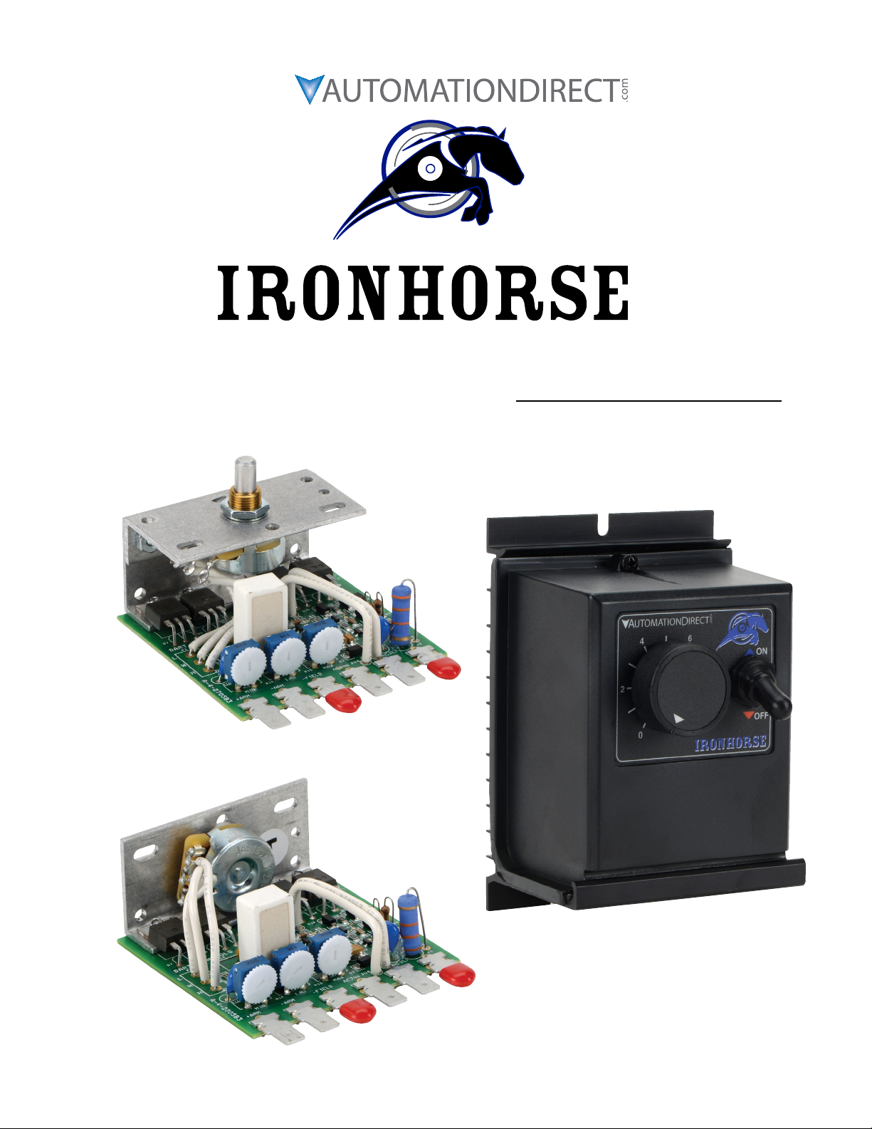
™
GSD3 Series DC Drives User Manual
User Manual Number: IH-GSD3-User-M
Page 1IronHorse GSD3 DC Drives User Manual – 1st Ed, Rev C – 10/15/2019
Page 2

~ WARNING ~
Thank you for purchasing automation equipment from Automationdirect.com®, doing business as AutomationDirect. We want your new automation equipment to operate safely. Anyone who installs or uses this equipment
should read this publication (and any other relevant publications) before installing or operating the equipment.
To minimize the risk of potential safety problems, you should follow all applicable local and national codes that
regulate the installation and operation of your equipment. These codes vary from area to area and usually change
with time. It is your responsibility to determine which codes should be followed, and to verify that the equipment,
installation, and operation is in compliance with the latest revision of these codes.
At a minimum, you should follow all applicable sections of the National Fire Code, National Electrical Code,
and the codes of the National Electrical Manufacturer’s Association (NEMA). There may be local regulatory or
government offices that can also help determine which codes and standards are necessary for safe installation and
operation.
Equipment damage or serious injury to personnel can result from the failure to follow all applicable codes
and standards. We do not guarantee the products described in this publication are suitable for your particular
application, nor do we assume any responsibility for your product design, installation, or operation.
Our products are not fault-tolerant and are not designed, manufactured or intended for use or resale as on-line
control equipment in hazardous environments requiring fail-safe performance, such as in the operation of
nuclear facilities, aircraft navigation or communication systems, air traffic control, direct life support machines,
or weapons systems, in which the failure of the product could lead directly to death, personal injury, or severe
physical or environmental damage (“High Risk Activities”). AutomationDirect specifically disclaims any
expressed or implied warranty of fitness for High Risk Activities.
For additional warranty and safety information, see the Terms and Conditions section of our catalog. If you have
any questions concerning the installation or operation of this equipment, or if you need additional information,
please call us at 770-844-4200.
This publication is based on information that was available at the time it was printed. At AutomationDirect we
constantly strive to improve our products and services, so we reserve the right to make changes to the products
and/or publications at any time without notice and without any obligation. This publication may also discuss
features that may not be available in certain revisions of the product.
Trademarks
This publication may contain references to products produced and/or offered by other companies. The product
and company names may be trademarked and are the sole property of their respective owners. AutomationDirect
disclaims any proprietary interest in the marks and names of others.
Copyright © 2013-2019 Automationdirect.com® Incorporated
All Rights Reserved
No part of this manual shall be copied, reproduced, or transmitted in any way without the prior, written consent of
Automationdirect.com® Incorporated. AutomationDirect retains the exclusive rights to all information included
in this document.
Page 2 IronHorse GSD3 DC Drives User Manual – 1st Ed, Rev C – 10/15/2019
Page 3
Contents
WARNING � � � � � � � � � � � � � � � � � � � � � � � � � � � � � � � � � � � � � � � � � � � � � � � � � � � � � � � � � � � � � � � � � 2
Trademarks � � � � � � � � � � � � � � � � � � � � � � � � � � � � � � � � � � � � � � � � � � � � � � � � � � � � � � � � � � � � � � � � 2
GSD3 DC Drives User Manual Overview� � � � � � � � � � � � � � � � � � � � � � � � � � � � � � � � � � � � � � � � � � � � � � � � 3
IronHorse GSD3 Series DC Drives General Information � � � � � � � � � � � � � � � � � � � � � � � � � � � � � � � � � � � � � � 4
Selection and Specifications � � � � � � � � � � � � � � � � � � � � � � � � � � � � � � � � � � � � � � � � � � � � � � � � � � � � � � 5
Dimensions � � � � � � � � � � � � � � � � � � � � � � � � � � � � � � � � � � � � � � � � � � � � � � � � � � � � � � � � � � � � � � � � 6
Installation and Wiring� � � � � � � � � � � � � � � � � � � � � � � � � � � � � � � � � � � � � � � � � � � � � � � � � � � � � � � � � 7
Trim Pot Adjustments � � � � � � � � � � � � � � � � � � � � � � � � � � � � � � � � � � � � � � � � � � � � � � � � � � � � � � � � � � 8
GSD3 DC Drives User Manual Overview
Overview of this Publication
The IronHorse GSD3 Series DC Drives User Manual describes the installation, configuration, and
methods of operation of the GSD3 Series DC Drives.
All information contained in this manual is intended to be correct. However, information and data in this
manual are subject to change without notice. AutomationDirect (ADC) makes no warranty of any kind
with regard to this information or data. Further, ADC is not responsible for any omissions or errors or
consequential damage caused by the user of the product. ADC reserves the right to make manufacturing
changes which may not be included in this manual.
Who Should Read This User Manual
This manual contains important information for those who will install, maintain, and/or operate any of the
GSD3 Series DC Drives.
Technical Support
By Telephone: 770-844-4200 (Mon.–Fri., 9:00 a.m.–6:00 p.m. ET)
On the Web: www.automationdirect.com
Our technical support group is glad to work with you in answering your questions. If you cannot find
the solution to your particular application, or, if for any reason you need additional technical assistance,
please call Technical Support at 770-844-4200. We are available weekdays from 9:00 a.m. to 6:00 p.m.
Eastern Time.
We also encourage you to visit our web site where you can find technical and non-technical information
about our products and our company. Visit us at www.automationdirect.com.
Special Symbols
When you see the “notepad” icon in the left-hand margin, the paragraph to its
immediate right will be a special note.
When you see the “exclamation mark” icon in the left-hand margin, the paragraph to its immediate right
Will be a Warning. this information could prevent injury, loss of property, or even death (in extreme
cases).
Page 3IronHorse GSD3 DC Drives User Manual – 1st Ed, Rev C – 10/15/2019
Page 4

IronHorse GSD3 Series DC Drives General Information
Carefully check the DC Drive for shipping damage. Report any damage to the
carrier immediately. Do not attempt to operate the drive if visible damage is
evident to either the circuit or to the electronic components.
Standard Features
• Dual voltage models of 12/24 VAC or 120/240 VAC input.
• Full wave bridge power supply.
• Adjustable minimum and maximum speeds.
• Adjustable IR Compensation.
• Fixed Acceleration (0.5 seconds).
• 5kΩ speed potentiometer with leads, knob & dial included.
• 25:1 speed range; 1% speed regulation.
• Shunt eld supply provided.
• Overload capacity of 200% for 1 minute.
• Transient voltage protection.
• Power on/off switch (enclosed models only).
• AC line fuse (120/240 VAC enclosed model GSD3-240-3N4 only)
• Enclosed models (GSD3-xxx-3N4) are rated NEMA 4.
Page 4 IronHorse GSD3 DC Drives User Manual – 1st Ed, Rev C – 10/15/2019
Page 5

Selection and Specifications
GSD3 Series DC Drives – Selection & Specifications
Model
Package Configuration open frame NEMA 4 open frame NEMA 4
Power Quality Form Factor 1.4
Input Voltage (@ 50/60 Hz) 12 or 24 VAC ±10% 120 or 240 VAC ±10%
Output Voltage 0–12 or 0–24 VDC 0–90 or 0–180 VDC
Shunt Field Voltage & Current
Output Rating (hp)
Output Current (continuous) 150 mA to 2A (DC) 150 mA to 3A (DC) 150 mA to 2A (DC) 150 mA to 3A (DC)
Current Overload Capacity 200% for 60s
Current Limit n/a
Transient Protection Metal Oxide Varistor (MOV)
I.R. Compensation adjustable – full range
Speed Adjustment 5kΩ potentiometer
Speed Range 25:1
Speed Regulation ±1% of base speed
Maximum Speed adjustable from 40% to 120% of base speed
Minimum Speed adjustable from 0% to 30% of maximum speed
Acceleration 0.5s (fixed)
Deceleration 0.5s (fixed)
Dynamic Braking no
Plugging Capability ** no
Electrical Connections spade connector lugs
External Fusing Required
Operating Temperature
Thermal Protection none
Mounting Orientation can be mounted in any orientation
Corrosive Gases NOT compatible with any corrosive gases
Weight
Agency Approvals RoHS
Replacement Potentiometer GSDA-5K
Manual Reverse Switch GSDA-MREV***
* For accessories details, please visit www.AutomationDirect.com.
** Plugging is a method of rapidly changing motor direction by reversing motor armature polarity, while the motor is still running.
*** To meet NEMA4 requirements, GSDA-MREV requires a user provided external exclosure.
GSD3-
24A-2CJ
10 VDC @ 12 VAC
20 VDC @ 24 VAC
1/50 – 1/40 @ 12V
1/25 – 1/20 @ 24V
Internal fusing is included which is adequate for GSD3-240-3N4 120 VAC line and neutral inputs.
Refer to “Fusing” (page 7) and “Wiring Diagrams” (page 7) for external fusing requirements for
-10 to 45 °C
[14 to 113 °F]
2.9 oz
[83g]
(1A max)
GSD3-
24A-2CL
2.6 oz
[75g]
Optional Accessories *
GSD3-24A-3N4
10 VDC @ 12 VAC
20 VDC @ 24 VAC
1/50 – 1/25 @ 12V
1/25 – 1/12 @ 24V
20.3 oz [575g]
(0.75A max)
other wiring configurations.
-10 to 40 °C
[14 to 104 °F]
GSD3-
240-2CJ
100 VDC @ 120 VAC
200 VDC @ 240 VAC
1/50 – 1/6 @ 90V
1/25 – 1/3 @ 180V
-10 to 45 °C
[14 to 113 °F]
2.9 oz
[83g]
GSD3-
240-2CL
(1A max)
2.6 oz
[75g]
Listed (E333109), RoHS
CULUS
GSD3-240-3N4
100 VDC @ 120 VAC
200 VDC @ 240 VAC
(0.75A max)
1/50 – 1/3 @ 90V
1/25 – 2/3 @ 180V
-10 to 40 °C
[14 to 104 °F]
20.3 oz [575g]
Page 5IronHorse GSD3 DC Drives User Manual – 1st Ed, Rev C – 10/15/2019
Page 6

Dimensions
GSD3-24x-2CJ (dimensions = in [mm])
GSD3-24x-2CL (dimensions = in [mm])
GSD3-24x-3N4 (dimensions = in [mm])
Page 6 IronHorse GSD3 DC Drives User Manual – 1st Ed, Rev C – 10/15/2019
Page 7

Installation and Wiring
Install open-frame drives in an enclosure with a volume at least three
times the volume of the open-frame drive.
Do not mount GSD3-24x-2Cx DC drive where ambient temperature is outside
the range of -10 to 45 °C (14 to 113 °F).
Do not mount GSD3-24x-3N4 DC drive where ambient temperature is outside
the range of -10 to 40 °C (14 to 104 °F).
improper installation or operation of this dc drive may cause injury to personnel or drive
failure. the drive must be installed in accordance With local, state, and national safety codes.
make certain that the poWer supply is disconnected before attempting to service or remove any
components!!! if the poWer disconnect point is out of sight, lock it in disconnected position
and tag it to prevent unexpected application of poWer. only a qualified electrician or service
personnel should perform any electrical troubleshooting or maintenance. at no time should
circuit continuity be checked by shorting terminals With a screWdriver or other metal device.
before attempting to Wire the dc drive, make sure all poWer is disconnected.
recheck code designation to assure proper voltage is present for the dc drive.
carefully select proper Wire size for current and voltage drop.
limit the voltage drop through the Wiring to 5% of the line voltage at full load.
caution!! turn poWer off While making Wiring connections.
caution!! do not attempt to perform a hi-pot test across the ac lines With the dc drive in
the circuit. this Will result in immediate or long-term damage to the drive.
Fusing
Refer to the wiring diagram for fusing information.
Terminals
GSD Model Type Wire Range Tightening Torque
GSD3-xxx-xxx Spade connector lugs n/a n/a
GSD3 Wiring Terminals
Wiring Diagram
GSD3-xxx-xxx Wiring Diagram
GSD3-xxx-xxx
Enclosed models
GSD3-xxx-3N4
include prewiring
inside of front
cover.
MAX
Speed Pot
(prewired)
* For wiring connections, use customer-supplied Sta-Kon 0.25 in x 0.25 in spade connectors or similar.
** +F connection is only for Shunt Wound motor; NOT for Permanent Magnet motor.
For motors with dual voltage field, i.e. 50/100V or 100/200V, connect the highest value.
I.R.
MIN
* Spade connector lugs
+ F
AC1(L)
AC2(N)
- FIELD
- ARM
+ ARM
motor plus (+) Field wire (of Shunt Wound motor) **
incoming AC line *** ****
incoming AC line ***
motor minus (-) Field wire (of Shunt Wound motor)
motor minus (-) Armature wire
motor plus (+) Armature wire
*** Use normal-blow fuses in series with all ungrounded (hot) AC inputs, rated to 125% of motor current.
NOTE: Fuse both AC input lines for 240 VAC input, where both lines are hot. For line-to-neutral
circuits, fuse the hot input line and connect it to AC1.
**** GSD3-240-3N4 drives include a replaceable built-in fuse wired in line with AC1.
(Fuse is 250VAC, 6.3A Littlefuse 21606.30 or equivalent.)
Page 7IronHorse GSD3 DC Drives User Manual – 1st Ed, Rev C – 10/15/2019
Page 8

Trim Pot Adjustments
Before the power is applied, the speed potentiometer and trim pots should be preset as follows:
TRIM POT PRESET
1) Preset trim pots in the counter-clockwise position (CCW).
2) Apply power and set GSD3-24x-3N4 power ON/OFF switches to the ON position.
3) Turn the Speed pot fully CW.
4) Adjust the MAX trim pot in the CW direction until the maximum desired speed is obtained.
5) Turn the Speed pot fully CCW.
6) Adjust the MIN trim pot in the CW direction until deadband or the desired speed is obtained.
TRIM POT ADJUSTMENT
The IR COMP trim pot is used as a regulation adjustment. If better motor regulation is needed between
minimum and maximum loads, then adjust the IR COMP trim pot as follows:
1) Turn the Speed pot CW to the 50% position.
2) Turn the IR COMP trim pot CW as needed to increase regulation.
3) Recheck and readjust the trim pots if necessary. Trim pot interaction with each other will be minimal.
Page 8 IronHorse GSD3 DC Drives User Manual – 1st Ed, Rev C – 10/15/2019
Page 9

BLANK
PAGE
Page 9IronHorse GSD3 DC Drives User Manual – 1st Ed, Rev C – 10/15/2019
Page 10

BLANK
PAGE
Page 10 IronHorse GSD3 DC Drives User Manual – 1st Ed, Rev C – 10/15/2019
Page 11

BLANK
PAGE
Page 11IronHorse GSD3 DC Drives User Manual – 1st Ed, Rev C – 10/15/2019
Page 12

Literature Number: LT134
Drawing Number: A-5-3901C
Page 12 IronHorse GSD3 DC Drives User Manual – 1st Ed, Rev C – 10/15/2019
 Loading...