

Page 1

GS4 Basic PID Setup QSG
We'll use a one-horsepower GS4-21P0 drive to control a motor with PID. This QSG assumes you have
already tested basic functionality of your drive. Here is a video link for basic setup if you need to do this:
https://www.youtube.com/watch?time_continue=48&v=jeKrK87EkvA
Below are the parameters we're going to set, and the values we're going to use in this document.
This initial group sets up Analog Input 1 for a 0-10v input signal, and selects it for both Remote and Local
selections, to minimize confusion. The PID Setpoint will be entered thru the drive keypad. PID Feedback
is selected in P4.02. P4.05 is set for 0-10v function.
P4.00 = 0 Keypad function "Remote Freq/PID SP Src" (PID Setpoint Source)
P4.01 = 0 Keypad function "Local Freq/PID SP Src" (PID Setpoint Source)
The two parameters above are set to make sure the drive is always in PID Mode. When `a GS4
powers up, it ALWAYS goes into "Remote" mode, and there is no way to change this. So even if
an operator changes the keypad to Local mode, the PID will still be active. After you have
established PID functionality, adjust those (if needed) to the requirements of the application.
P4.02 = 5 PID Feedback funtion "Analog Input 1 Function"
P4.05 = 0 0-10v function "AI 1 -I/V Selection" ( Make sure to check AI 1 slider switch is in
0-10v position as well)
P7.00 = 2 Forward acting (heating) Local and Remote "PID Action mode"
Where the GS4 is substantially different from previous GS2 and GS3 drives, is setting up the range of
the sensor, and configuring the display for the PID Setpoint.
P8.00 = 30 User Defined "User Display"
P8.01 = 0 Freq Setpoint "Start-up Display function"
P8.02 = 01C1 "psi" units, with 1 decimal point, "User Defined Format". This parameter needs
some explanation. The 01C portion selects psi, there are many other unit
choices shown in the manual for this parameter, such as rpm, ft/min, Degree C
or F, etc. The "1" at the far right, selects how many decimal places. A value of
01C2 would give 2 decimal places for PSI.
P8.03 = 120.0 Represents a pressure sensor with upper range of 120 psi. "User Defined Max".
Set this number to the value of YOUR sensor.
Page 2
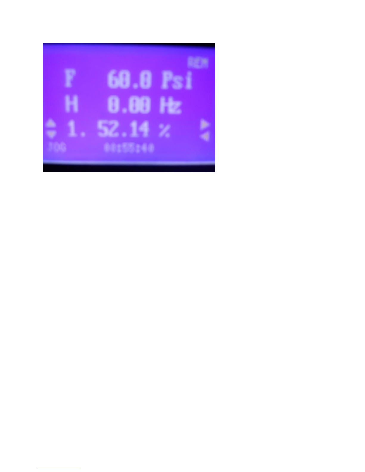
In the picture of the GS4 display above, the "F" represents the PID Setpoint ( there isn't any way to
display "PID Setpoint" unfortunately). In this case, the PID SP is exactly at the mid-point ( 60.0 Psi) of the
120 Psi range we set in the step above the picture.
The bottom row, with the arrows pointing up and down on the left, and another set of arrows on the
right, is the Status line. There are approx 40 status items you can scroll left to right thru, in this case, the
"1." represents the Analog In #1 value. Note that it's at 52.14% of its' range. so it's just above the 50%
setting of 60.0 Psi for F ( 60.0 psi is 50% of 120.0 psi we set as max range in P8.03).
So the H ( Output Frequency) is 0.0, since the PID PV is slightly above the PID SP represented by F, and
the PID is happy.
In the picture below, the Analog In #1 value "1." is lowered slightly to approx 38%, and the drive starts
ramping up the H Frequency Output (here at 31.41 Hz), to try to bring the PV "1." back up to the SP of
"F".
Page 3

 Loading...