

Page 1

DURApulse GS20 AC Drive Quick-Start Guide
R/L1
S/L2
T/L3*
R/L1
S/L2
T/L3*
U/T1
V/T2
W/T3
3
~
R1C
R1
R1C and R1 are the relay output terminals.
Input: one-phase / three-phase* power
DC reactor (optional)
Brake resistor (optional)
Jumper
Motor
Circuit Breaker or Fuse
MC
ON
MC
OFF
It is recommended that
you install a protective
circuit at R1C – R1 to
protect the drive from
damage.
When a fault occurs, the MC contactor
switches to OFF to shut off the drive input
power and protect the power system.
MC
DO
DCM
Multi-function output
frequency terminals
30 VDC / 30 mA 33 kHz
DO2
DOC
DO1
Multi-function output
terminal 48 VDC / 50 mA
Multi-function output
terminal 48 VDC / 50 mA
Multi-function output
common terminal (photocoupler)
USB Port
Communication card/
DC 24V external power supply card
Option Slot
250 VAC / 3 A (N.O.)
250 VAC / 3 A (N.C.)
R1O
R1C
R1
250 VAC / 1.2 A (N.O)
Multi-function relay output terminals
Estimate at COS (0.4)
Modbus RS-485
8
1
S
G
+
S
G
N
D
Control terminals
Shielded leads & Cable
Main circuit terminals
NOT
E
DI1/FWD
DI2/REV
DI3
DI4
DI5
DI6
DI7
DCM
+
24V
+
24V
Default
FWD/STOP
REV/STOP
Multi-step speed 1
Multi-step speed 2
Multi-step speed 3
Multi-step speed 4
N/A
Digital Signal Common
*DI7 can input 33 kHz pulses.
*Do NOT apply the mains voltage directly to
external terminals.
Default:
NPN (SINK) Mode (internal power)
Please refer to the wiring of NPN mode and PNP mode.
STO1
+24 V
STO2
ESTOP
+24 VDC
Safety PLC
NOT
E
SCM
*
1
It is a short circuiting jumper installed between
+24 V, S1 and S2 short when GS20 leaves the factory.
Remove this short circuiting jumper before using the
safety function while wiring.
*
1:
*
2:
The +24 V is for STO only, and cannot be used for any
other purpose.
2
*
AI1
ACM
+
10V
3
2
1
0 – 10 VDC
AI2
0 – 10 VDC
+
10 VDC / 20 mA
-10 VDC – 10 VDC
0 – 20 mA / 4
–
20 mA
Analog Signal common
Analog Multi-function output
terminal 0 – 10 VDC /
0 – 20 mA / 4 – 20 mA
Analog Signal common
+
5KΩ
P
N
P
NPN
P
N
P
N
P
N
0
-
1
0
V
AFM
–
0
-
1
0
V
AO1
0
–
20 mA
0
–
10 V
0
-
2
0
m
A
4
-
2
0
m
A
ACI
0 – 20 mA
4 – 20 mA
0
-
2
0
m
A
4
-
2
0
m
A
AI2
0
–
20 mA
4
–
20 mA
0
–
AO1
GS20 AC Drives Installation Instructions
Sensorless Vector Control Variable Frequency Micro-drive
• Please read this instruction sheet thoroughly before installation and retain for later
reference.
• To ensure the safety of operators and equipment, only qualified personnel familiar
with AC drives should install, wire, program, and operate the GS20 drive. Always read this instruction sheet
thoroughly before using the GS20 drive, especially the WARNING, DANGER and CAUTION notes. If you have any
questions, please contact AutomationDirect.
PLEASE READ PRIOR TO INSTALLATION FOR SAFETY
• The ground terminal of the GS20 drive must be grounded correctly. The grounding method
must comply with the laws of the country where the GS20 drive is to be installed.
• After power has been turned off, the capacitors in the GS20 drive may retain a charge for
several minutes. To prevent personal injury, visually verify that the “CHARGE” LED has
turned off. Then measure to confirm that the DC bus voltage level between terminals (+1)
and (-) is less than 25VDC before touching any terminals. (Capacitor discharge will take at
least 5 minutes for most GS20 models)
• The CMOS ICs on the internal circuit boards of the GS20 drive are sensitive to static
electricity. Please DO NOT touch the circuit boards with your bare hands before taking
DANGER
WARNING
CAUTION
anti-static measures. Never disassemble the internal components or circuits.
• If wiring changes must be made, turn off power to the GS20 drive before making those
changes. Allow the internal DC bus capacitors in the GS20 drive sufficient time to discharge
prior to making changes in power or control wiring. Failure to do so may result in short
circuit and fire. To ensure personal safety, allow DC bus voltage to discharge to a safe level
before making wiring changes to the GS20 drive.
• DO NOT install the GS20 drive in locations subject to high temperature, direct sunlight, or
flammable materials.
• Never apply power to the output terminals U/T1, V/T2, W/T3 of the GS20 drive. If a fault
occurs during operation of the GS20 drive, refer to the fault code descriptions and corrective
actions to reset the fault before attempting to operate the GS20 drive.
• DO NOT use Hi-pot test for internal components. The semi-conductors in the GS20 drive are
easily damaged by high voltage.
• Long motor lead lengths may result in reflective wave due to impedance mismatch between
the motor cable and the motor. Reflective wave may damage the insulation of the motor.
To avoid the possibility of reflective wave damage, use an inverter-rated motor with an
insulation rating of 1600 volts. A load reactor installed between the GS20 drive and motor
will help to mitigate reflective wave.
• Nominal supply voltage to the GS20 drive should be less than or equal to 120/240/480 volts
AC depending on GS20 model.
• Nominal supply current capacity should be less than or equal to 100kA for all GS20 models.
• The GS20 drive must be installed in a clean, well-ventilated and dry location, free from
corrosive gases or liquids.
• The GS20 drive must be stored within an ambient temperature range from –40°C to +85°C,
and relative humidity range of 0% to 90% without condensation.
• Do not apply AC power to the GS20 drive with the front cover removed. Following a fault of
the GS20 drive, wait 5 seconds before pressing the RESET key.
• To improve power factor, install a line reactor ahead of the GS20 drive. Do not install power
correction capacitors in the main AC supply circuit to the GS20 drive to prevent drive faults
due to over-current.
Wiring Diagrams
RFI Jumper Removal
If the power distribution system supplying the GS20 AC drive is a floating (IT) or an
asymmetric ground system (including most 120V inputs), the RFI jumper must be
removed.
Removing the RFI jumper uncouples the internal RFI capacitor (filter capacitor)
between the GS20 drive frame and circuitry to avoid damaging those circuits and
(according to IEC 61800-3) to reduce ground leakage current.
GS20 Frame A through F
Note: Remove Clip
Main Wiring (Power Circuit)
For main (power) wiring terminal specifications, Please refer to “Specifications for Wiring Terminals –
Main-Circuit Terminals” (page 2).
GS20 all Frames
*(Note that 1-phase drives do not have a T/L3 terminal)
GS20 Control Terminal Wiring
FWD (DI1)
REV (DI2)
DI7
FWD (DI1)
REV (DI2)
DI7
DCM
Minimum Wiring
• AC input power to R/L1, S/L2, T/L3 (for single-phase input, use two of the terminals) (For applicability of 1-phase
input power, please refer to Chapter 1 of the DURApulse GS20 AC Drives User Manual at AutomationDirect.com.)
• Ground from the power supply
• Drive power to the motor (U, V, W on T1, T2, T3) (For use with 3-phase motors only!)
• Ground to the motor
• STO1 and STO2 (both must be wired through appropriate N.C. safety-rated contacts to DCM or the
factory-installed jumpers must be left in place)
With this minimal wiring, the drive can be operated via the keypad to test the motor and drive installation.
See the “Parameter Set Up” (page 4) section to configure the drive for keypad operation.
Recommended Safety Wiring
We strongly recommend that customers use the STO safety feature.
The Safe Torque Off (STO) function turns off the power supplied to the motor through the hardware, so
that the motor cannot produce torque. This method of removing power from the motor is considered an
emergency stop, also known as “coast to stop.”
To use this feature, disconnect the appropriate factory-installed jumpers and wire a safety relay, safety PLC, or
E-Stop pushbutton as shown. See Main Wiring (Power Circuit) (page 1) for wiring the GS20.
GS20_QSP 1st Edition, Rev B 01/29/2021
DCM
FWD (DI1)
REV (DI2)
DI7
DCM
FWD (DI1)
REV (DI2)
DI7
DCM
DURApulse GS20 AC Drive Quick-Start Guide – 1st Ed, Rev B 01/29/2021
Page 1
Page 2

DURApulse GS20 AC Drive Quick-Start Guide
P02.00 External Terminal Control Circuits
Setting value: 1
Two-wire operation control
FWD / STOP
REV / STOP
Setting value: 2
Two-wire operation control
RUN / STOP
FWD / REV
FWD/DI1
REV/DI2
DCM
FWD/DI1
REV/DI2
DCM
FWD/DI1
Setting value: 3
Three-wire operation control
DI3
REV/DI2
DCM
Specifications for Wiring Terminals – Control Circuit
GS20-xxxx All Models; All Frame Sizes
Terminal Wire Gauge Torque
Control
Relay
24–18 AWG
[0.21–0.82 mm2]
24–16 AWG
[0.21–1.31 mm2]
GS20(X)
GS20(X)
GS20(X)
n/a (spring terminals)
5kg·cm
[4.3 lb·in]
Recommended models or dimensions for ferrule terminals
Wire Gauge Manufacturer Model Name A (MAX) B (MAX) D (MAX) W (MAX)
0.25 mm2
[24 AWG]
0.34 mm2
[22 AWG]
0.5 mm2
[20 AWG]
PHOENIX
CONTACT
PHOENIX
CONTACT
PHOENIX
CONTACT
Z+F V30AE000006 14 8 2.6 1.15
AI 0,25- 8 YE 12.5 8 2.6 1.1
AI 0,34- 8 TQ 12.5 8 3.3 1.3
AI 0,5 - 8 WH 14 8 3.5 1.4
Specifications for Wiring Terminals – Main-Circuit Terminals
Notes:
• If you install at Ta 45°C above environment, please use copper wire with a 600V voltage rating and
temperature resistance of 90°C or higher.
• For UL compliant installation, you must:
1) Use 75°C temperature resistant copper wire or better. Do not reduce wire gauge when using higher
temperature wire.
2) Use the specific ring lug part listed in the table below.
3) Use crimp tool KST2000D-1322 or IZUMI 5N18 for 22–8 AWG wire, or
IZUMI 9H-60 for 6–4 AWG wire.
Specifications for Wiring Terminals – Main-Circuit Terminals (continued)
Drive Models
GS21-11P0
GS21-22P0
GS21-23P0
GS23-23P0
GS23-25P0
Frame C
GS23-43P0
GS23-45P0
GS23-53P0
GS23-55P0
GS23-27P5
GS23-47P5
GS23-4010
Frame D
GS23-57P5
GS23-5010
Max Wire
Gauge
8AWG
[8.4 mm2]
8AWG
[8.4 mm2]
Min Wire
Gauge
10AWG
[5.3 mm2]
8AWG
[8.4 mm2]
12AWG
[3,3 mm2]
10AWG
[5.3 mm2]
14AWG
[2.1 mm2]
12AWG
[3,3 mm2]
8AWG
[8.4 mm2]
10AWG
[5.3 mm2]
Ring
Lug P/N
RNBS
5-4
RNBS
8-4
RNBS
5-4
RNBS
2-4
RNBS
5-4
RNBS 8-4
RNBS 5-4
Screw
M4
M4
Torque
(±10%)
20 kg-cm
[17,4 lb-in.]
[1.96 N·m]
20 kg-cm
[17,4 lb-in.]
[1.96 N·m]
Ring Lug Dimensions (mm)
Dimension Value Min/Max
A 17.8 Max
B 5.0 Max
C 6.1 Min
D 7.2 Max
d2 4.3 Min
E 13.0 Min
F 5.5 Min
W 8.0 Max
t 1.2 Max
Dimension Value Min/Max
A 17.8 Max
B 5.0 Max
C 6.1 Min
D 7.2 Max
d2 4.3 Min
E 13.0 Min
F 5.5 Min
W 8.0 Max
t 1.2 Max
PNP
AI2
DI6
4-20mA
0-20mA
SG+
AO1
DI7
SG-
NPN
SGND
DO1
+24V
DO2
+24V
DOC
USB
DATAMATRIX
24P
32637012
SLOT 1
RELAY
R1
R1C
R1O
RS485
Port
DO
DCM
DCM
4-20mA
0-20mA
AI2
+24V
Safety function
+10V
REV
FWD
0-10V
STO1
DI3
STO2
ACM
DI4
0-10V
AO1
SCM
AI1
DI5
Wiring Precautions
1) The factory default condition is +24 V/ S1/ S2 shorted by jumper, as shown in the block 1 of the figure above.
Refer to the wiring chapter of the User Manual for more details.
2) The +24 V power supply for safety function is only for STO use and cannot be used for other purposes.
3) The RELAY terminal uses the PCB terminal block:
• Tighten the wiring with a 3.5 mm width and 0.6 mm thickness slotted screwdriver.
• The ideal length of stripped wire at the connection side is 6–7 mm.
• When wiring bare wires, make sure they are perfectly arranged to go through the wiring holes.
4) The control circuit terminal uses a spring clamp terminal block:
• Tighten the wiring with a 2.5 mm width and 0.4 mm thickness slotted screwdriver.
• The ideal length of stripped wire at the connection side is 9 mm.
Drive Models
GS21-10P2
GS21-20P2
GS23-20P2
GS23-20P5
GS21-10P5
GS21-20P5
Frame A
GS23-40P5
GS23-21P0
GS23-41P0
GS23-51P0
GS23-22P0
GS23-42P0
Frame B
GS23-52P0
GS21-21P0
Max Wire
Gauge
14AWG
[2.1 mm2]
12AWG
[3,3 mm2]
Min Wire
Gauge
16AWG
[1.3 mm2]
18AWG
[0.82 mm2]
14AWG
[2.1 mm2]
18AWG
[0.82 mm2]
16AWG
[1.3 mm2]
18AWG
[0.82 mm2]
14AWG
[2.1 mm2]
Ring
Lug P/N
RNBS
2-3.7
RNBS
1-3.7
RNBS
2-3.7
RNBS
1-3.7
RNBS
2-3.7
RNBS
1-3.7
RNBS
2-4
Screw
M3.5
M4
Torque
(±10%)
9 kg-cm
[7,8 lb-in.]
[0.88 N·m]
15 kg-cm
[13,0 lb-in.]
[1.47 N·m]
Ring Lug Dimensions (mm)
Dimension Value Min/Max
A 9.8 Max
B 3.2 Max
C 4.8 Min
D 4.1 Max
d2 3.7 Min
E 13.0 Min
F 4.2 Min
W 6.6 Max
t 0.8 Max
Dimension Value Min/Max
A 12.1 Max
B 3.6 Max
C 6.1 Min
D 5.6 Max
d2 4.3 Min
E 13.0 Min
F 4.5 Min
W 7.2 Max
t 1 Max
GS23-2010
GS23-2015*
Frame E
GS23-4015
6AWG
[13.3 mm2]
4AWG
[21.2 mm2]
6AWG
[13.3 mm2]
6AWG
[13.3 mm2]
4AWG
[21.2 mm2]
8AWG
[8.4 mm2]
RNBS
14-5
RNBS
22-5
RNBS 8-5
M5
25 kg-cm
[21,7 lb-in.]
[2.45 N·m]
GS23-4020
GS23-2020
GS23-4025
Frame F
2AWG
[33.6 mm2]
GS23-4030
* The GS23-2015 drive must be wired with a ring terminal of the specified dimensions.
2AWG
[33.6 mm2]
6AWG
[13.3 mm2]
4AWG
[21.2 mm2]
RNBS
38-6
RNBS
14-6
RNBS
22-6
M6
40 kg-cm
[34,7 lb-in.]
[3.92 N·m]
Dimension Value Min/Max
A 27.1 Max
B 6.1 Max
C 10.5 Min
D 11.5 Max
d2 5.3 Min
E 13.0 Min
F 6.5 Min
W 12.2 Max
t 1.7 Max
Dimension Value Min/Max
A 35.0 Max
B 9.0 Max
C 13.3 Min
D 14.0 Max
d2 6.2 Min
E 13.0 Min
F 19.5 Min
W 18.0 Max
t 1.8 Max
GS20_QSP 1st Edition, Rev B 01/29/2021
DURApulse GS20 AC Drive Quick-Start Guide – 1st Ed, Rev B 01/29/2021
Page 2
Page 3
DURApulse GS20 AC Drive Quick-Start Guide
R
F
P
P
P
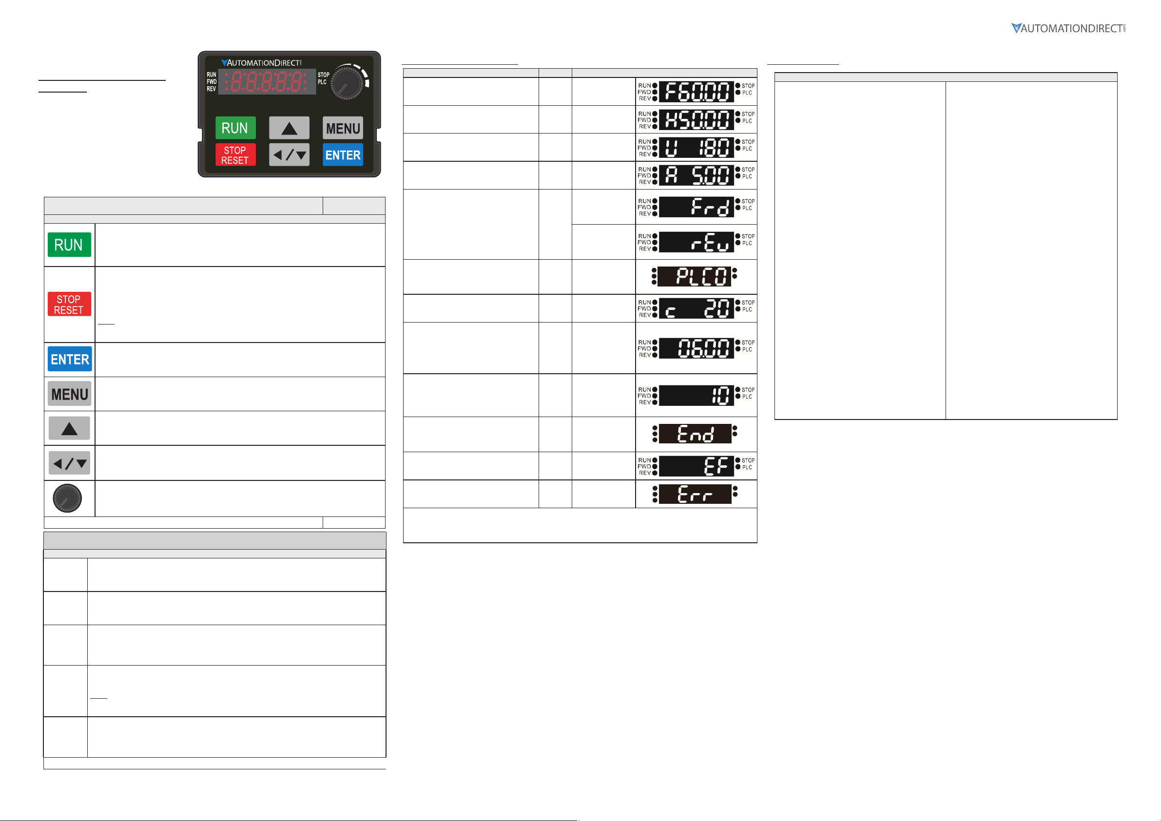
Digital Keypad Functions and
Indications
Description of the functions of the keys and
indicators of the GS20 AC Drive Keypad.
NOTE: Drive default is AUTO mode. There is
no indication from the keypad of the mode.
Local mode can be set with I/O configuration
or GS4-KPD only.
Descriptions of Keypad Functions (continued)
Descriptions of Keypad Functions
RUN Key
• Valid only when the source of operation command is from the keypad.
• RUN can be pressed even when drive is in process of stopping.
• When in “LOCAL” mode, RUN is valid only when the source of operation command is from
the keypad (drive default is Auto mode, Local mode can be set with I/O or GS4-KPD only).
STOP/RESET Key
This key has the highest processing priority in any situation.
• When the drive receives a STOP command, whether or not the drive is in operation or stop
status, the drive will execute a "STOP" command.
• The RESET key can be used to reset the drive after a fault occurs. For those faults that can't
be reset by the RESET key, see the fault records after pressing MENU key for details.
N OTE: The ability to STOP the drive from the keypad is effective ONLY if the drive is configured
to RUN and/or STOP from the keypad. Keypad STOP can be disabled by parameter 00.32,
Digital Keypad STOP Function.
ENTER Key
Press ENTER to go to the next menu level or accept parameter entry. If it is the last level, then
press ENTER to execute the command.
MENU Key
Press MENU to return to the Main Menu or cycle through the available menu options.
Direction: Up
Press to make the value set on the current menu/parameter higher.
Direction: Left/Down
• Press to make the value set on the current menu/parameter lower.
• In the menu/text selection mode, the arrows are used for item selection. Long press the
MENU key to use the left direction function.
Frequency Setting Dial (Potentiometer)
The dial can be set as the main frequency input. Set Parameter 00-20 or 00-30 to equal
‘7-Digital Keypad Dial’.
Continued on next page.
Descriptions of LED Functions (continued)
Descriptions of LED Functions
Steady ON: Drive is running.
RUN
Blinking: Drive is stopping or in base block.
Steady OFF: Drive is not running.
Keypad Navigation Example
Instruction Press Key Display Will Show
First menu to display after power up. n/a
Press MENU once from startup. MENU
Press MENU twice from startup. MENU
Press MENU three times from startup. MENU
Press MENU four times from startup.
Displays Frd if the drive is currently
configured for Forward operation. Press
the UP or DOWN key to change to Reverse.
Press ENTER to confirm the change.
Press MENU five times from startup.
Displays the current PLC setting. Press the
UP or DOWN arrow keys to change the
PLC setting, then press ENTER to confirm.
Enable the counter by setting parameter
00.04 to 1. See the user manual for full
instructions on using the counter.
After selecting the desired menu option,
press ENTER to bring up the parameter
number (Format XX.YY). Use the UP
and DOWN arrow keys to change the
parameter number as needed, then press
ENTER to adjust the parameter value.
From the parameter number screen, press
ENTER to bring up the current value of
the selected parameter. Use the UP and
DOWN arrows to adjust the value. Press
ENTER again to confirm the choice.
Once a desired parameter value has been
set using the UP and DOWN arrow keys,
press ENTER to save the choice and display
End message.
Displays when an external fault is detected. n/a
Displays when data is not accepted or the
value exceeded
Scroll sequentially through the rest of the parameters in the “Basic Configuration” Quick-Start group, and set those
parameters as needed for your application.
After changing all of the applicable parameters, press “MENU” key to return to the Menu screen, and then press
“ESC” key to return to the home screen.
DOWN
DOWN
ENTER,
DOWN,
ENTER,
DOWN
Displays the
present frequency
setting of the drive
Displays the actual
output frequency
of the drive
Displays user
defined output
Displays output
current
Displays the
Forward command
if configured for
MENU,
Forward operation.
UP/
Displays the
ENTER
Reverse command
if configured for
Reverse operation.
MENU,
Displays the
UP/
current PLC
setting.
ENTER
Displays the
MENU
counter value
UP/
Displays the
parameter number
ENTER
Displays the value
UP/
of the selected
parameter
End message.
Displays when data
ENTER
has been accepted
and stored
External fault
message
n/a Error message.
UN
WD
R EV
R UN
FWD
R EV
R UN
FWD
R EV
GS20 Fault Codes
STO
PL C
STO
PL C
STO
PL C
0: No Error
1: Overcurrent during Accel (ocA)
2: Overcurrent during Decel (ocd)
3: Overcurrent during constant speed (ocn)
4: Ground Fault (GFF)
6: Overcurrent during Stop (ocS)
7: Overvoltage during Accel (ovA)
8: Overvoltage during Decel (ovd)
9: Overvoltage during constant speed (ovn)
10: Overvoltage during Stop (ovS)
11: Low voltage during Accel (LvA)
12: Low voltage during Decel (Lvd)
13: Low voltage during constant speed (Lvn)
14: Low voltage during Stop (LvS)
15: Input phase loss (OrP)
16: IGBT Overheat 1 (oH1)
18: Thermister 1 open (tH1o)
21: Drive over-load (oL)
22: Electronics thermal relay protection 1 (EoL1)
23: Electronics thermal relay protection 2 (EoL2)
24: Motor Overheat-PTC (oH3)
26: Over Torque 1 (ot1)
27: Over Torque 2 (ot2)
28: Under current (uc)
31: Memory read-out error (cF2)
33: U phase current sensor detection error (cd1)
34: V phase current sensor detection error (cd2)
35: W phase current sensor detection error (cd3)
36: Clamp current detection error (Hd0)
37: Over-current detection error (Hd1)
40: Auto tuning error (AuE)
41: PID Feedback loss (AFE)
42: PG feedback error (PGF1)
43: PG feedback loss (PGF2)
44: PRG feedback stall (PGF3)
45: PG slip error (PGF4)
48: Analog current input loss (ACE)
49: External Fault input (EF)
50: Emergency Stop (EF1)
51: External Base Block (bb)
52: Password Error (Pcod)
Fault Codes
54: Communication Error (CE1)
55: Communication Error (CE2)
56: Communication Error (CE3)
57: Communication Error (CE4)
58: PC Communication Time Out (CE10)
61: Y-Delta connection Error (ydc)
62: Decel Energy Backup Error (dEb)
63: Slip Error (oSL)
72: Channel 1 (S1~DCM) safety loop error (STL1)
76: Safety Torque Off (STO)
77: Channel 2 (S2~DCM) safety loop error (STL2)
78: Internal loop error (STL3)
79: U Phase over current before run (Aoc)
80: V Phase over current before run (boc)
81: W Phase over current before run (coc)
82: U Phase output phase loss (oPL1)
83: V Phase output phase loss (oPL2)
84: W Phase output phase loss (oPL3)
87: Drive over load in low frequency (oL3)
89: Initial rotor position detection error (roPd)
121: Internal communication error (CP20)
123: Internal communication error (CP22)
124: Internal communication error (CP30)
126: Internal communication error (CP32)
127: Software version error (CP33)
128: Over-torque 3 (ot3)
129: Over-torque 4 (ot4)
134: Electronics thermal relay 3 protection (EoL3)
135: Electronics thermal relay 4 protection (EoL4)
140: GFF detected when power on (Hd6)
141: GFF occurs before run (b4GFF)
142: Auto tuning error 1 (DC test stage) (AUE1)
143: Auto tuning error 2 (High frequency test stage)
(AUE2)
144: Auto tuning error 3 (Rotary test stage) (AUE3)
Steady ON: Drive is operating in Forward mode.
FWD
REV
STOP
PLC
GS20_QSP 1st Edition, Rev B 01/29/2021
Blinking: Drive is changing direction.
Steady OFF: Drive is operating in Reverse mode.
Steady ON: Drive is operating in Reverse mode.
Blinking: Drive is changing direction.
Steady OFF: Drive is operating in Forward mode.
Steady ON: Drive is stopped or in the process of stopping.
Blinking: Drive is in standby (run but does not output).
Steady OFF: Drive is not currently executing an operational (STOP) command.
N OTE: The ability to STOP the drive from the keypad is effective ONLY if the drive is configured to
RUN and/or STOP from the keypad. Keypad STOP can be disabled by parameter 00.32, Digital
Keypad STOP Function.
Steady ON: PLC STOP (PLC 2) initiated.
Blinking: PLC Run (PLC1) inititated.
Steady OFF: No PLC functions implemented (PLC 0).
Continued on next page.
DURApulse GS20 AC Drive Quick-Start Guide – 1st Ed, Rev B 01/29/2021
Page 3
Page 4
DURApulse GS20 AC Drive Quick-Start Guide
Introduction – How To Get Started
Automationdirect.com would like to thank you for your purchase of the Durapulse GS20 AC drive. The GS20
drive is a state-of-the-art, full-featured AC drive. The Quick-Start Guide below will introduce you to many of
the GS20 drive features and help you configure the GS20 drive in a minimum amount of time.
STO (Safe Torque Off) / Emergency Stop
The GS20 drive offers Safe Torque Off (STO) functionality, instead of a standard Emergency Stop circuit. STO
provides the ability to immediately turn off the output of the GS20 drive in the event of an emergency, without
the need for an emergency stop contactor between the drive and motor.
Please see the Control-Circuit Wiring diagrams (page 1) for how to wire the STO circuit. From the factory,
the GS20 STO terminals are jumpered and the STO circuitry of the drive is bypassed. STO is recommended for
personnel safety.
After wiring the drive (but before applying power), the first thing you should do is press the E-stop button (or
otherwise break the safety circuit) and verify that the circuit between the STO1/STO2 terminals and the STO
+24V terminal is not connected. If these circuits are open, the STO feature will stop all power from going to the
motor and there will be no danger of unexpected movement when you power up the drive.
Powering Up the GS20 Drive
Apply AC line power to the GS20 drive, but don’t engage the safety circuit yet (keep the E-stop PB pushed in).
Starting, Stopping, and Controlling the Speed of the GS20 Drive
Out of the box GS20 drives are set to use the keypad buttons to RUN and STOP the drive and vary the drive
speed. The drive can also be configured to run from potentiometers, external pushbuttons, Ethernet
communication, etc.
Do not attempt to run the motor yet. Certain parameters (especially the motor protection parameters) must
be set first.
Configure the Drive
The tables below list those parameters typically used in most applications. You can navigate to any of these
parameters through the keypad. (Refer to page 3 for information and instructions for using the Digital
Keypad.)
All applications need to configure the parameters in the “Quick Configuration” table. At minimum, you MUST
configure these motor parameters before operating the drive:
• 01.02 Motor1 Max Output Voltage (this will typically be either 230V or 460V)
• 05.01 Motor1 Rated Amps (depends on the motor)
• 01.01 Motor1 Max Output Frequency (this will typically be 50Hz or 60Hz)
The main configuration parameters required to get your drive up and running are included in this guide.
For more advanced configuration options, please see the User Manual. Your application will dictate which
parameters need to be configured. It is NOT necessary to configure every parameter listed in the tables in the
User Manual, use only those you need.
Parameter Groups
Group Number Group Category
00 Drive Config
01 Basic Config
02 Digital I/O Config
03 Analog I/O Config
04 Multi-Step Speed Config
05 Motor Config
06 Protection Config
07 Special Parameters
08 PID Config
09 Communications Config
10 Speed Control Config
11 Advanced Config
13 Macro Config
14 Protection (2) Config
After configuring the minimum settings, you can now engage the safety circuit. The RUN and STOP/RESET
buttons should Start and Stop the drive. To adjust the output frequency, press the MENU button until the
frequency screen appears. Use the Up and Down arrow buttons to adjust the frequency, the press ENTER to
confirm. Press ENTER again to return to the main menu.
Parameter Set Up
DURApulse GS20 AC Drives offer parameter setup from the keypad for some of the most common drives
applications. Choose parameters from the table below, then set the applicable parameters for that
application as shown.
To Configure Parameters:
From the power up screen:
1) Press MENU until you see H 0.00 (this is the actual drive frequency) and press ENTER.
2) Use the UP/DWN arrows to select the parameter group you want and press ENTER.
3) Use the UP/DWN arrows to select the parameter number you want within that group and press ENTER.
4) Change the value of the parameter using the UP/DWN arrows and press ENTER.
5) Press MENU to exit back to the main menu.
6) Repeat as needed until all required parameters are configured.
Please refer to the user manual if you need more detailed information about the
parameters.
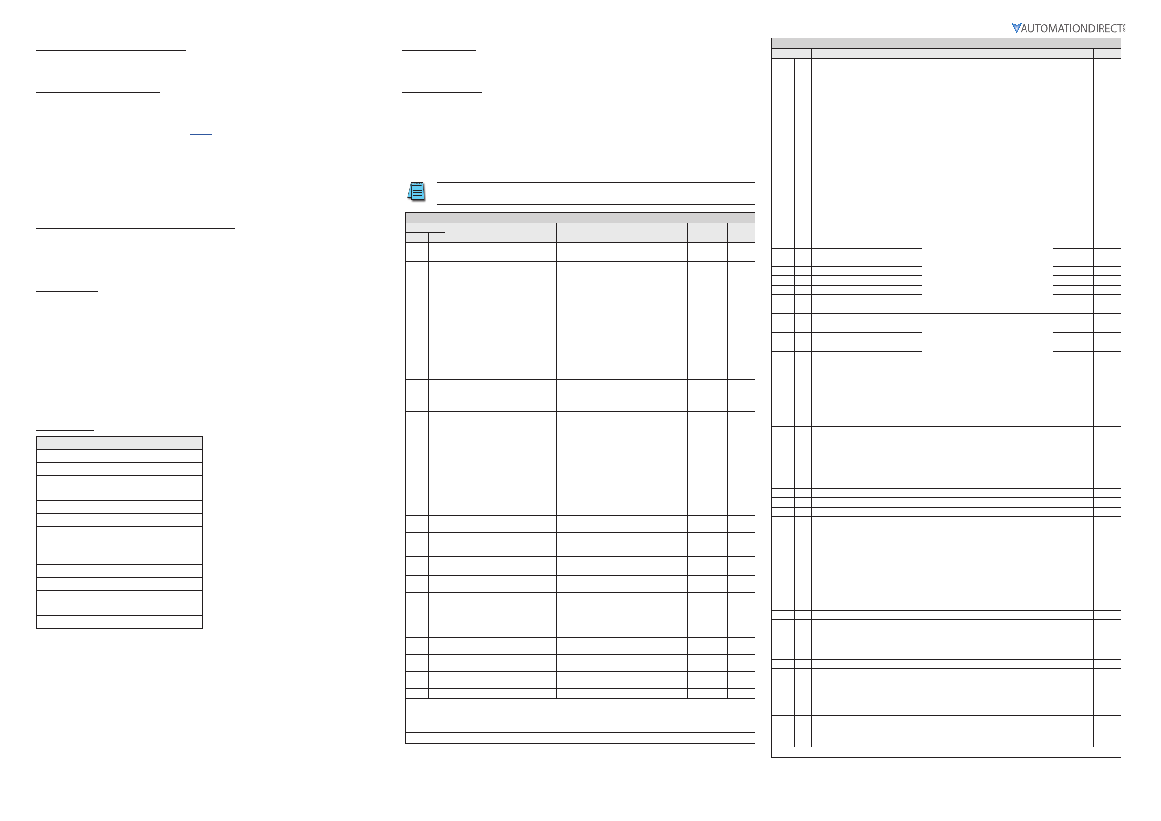
DURApulse GS20 Parameter Settings – Quick Configuration*
Parameter
Group #
* Assumes default V/Hz mode with no feedback. To change control modes see complete parameter listing in User manual.
** Reboot drive after resetting defaults.
Note: Drive default is Auto mode and cannot be changed from the keypad. For Local/Hand, use Discrete input configuration
settings (P02.00–P02.07) and P00.29–P00.31.
Description Range Default User
00 00 GS20 Model ID Read Only n/a
00 01 Displays AC drive rated current Displays value based on model n/a
00 02 Restore to default**
00 06 Firmware Version Read Only n/a
00 10 Control Mode
00 11 Speed Control Mode
00 16 Load Selection
00 20 Frequency Command Source (Auto)
00 21 Operation Command Source (Auto)
00 22 Stop Method
00 23 Motor Direction Control
01 00 Motor 1 Max Frequency 0.00-599.00 Hz 60
01 01 Motor 1 Base Frequency 0.00-599.00 Hz 60
01 02 Motor 1 Rated Voltage
01 09 Startup Frequency 0.00-599.0 Hz 0.5
01 10 Output Frequency Upper Limit 0.00-599.0 Hz 599.0
01 11 Output Frequency Lower Limit 0.00-5.99.0 Hz 0.00
01 12 Acceleration Time 1
01 13 Deceleration Time 1
01 20 Jog Acceleration Time
01 21 Jog Deceleration Time
01 22 Jog Frequency 0.00-599.0 Hz 0.5
0=No function
1=Parameter write protect
2=Reset to GS2 mode (1 of 2)
5=Reset kWH display to 0
6=Reset PLC
7=Reserved
8=Keypad doesn’t respond
9=Reset 50Hz defaults
10=Reset 60Hz defaults
11=Reset 50Hz defaults (keep user config)
12=Reset 60Hz defaults (keep user config)
20=Reset to GS2 mode (2 of 2)
0=Speed mode
2=Torque mode
0=VF (IM V/F control)
1=VFPG (IM V/F control + Encoder)
2=SVC (Parameter 05.33 set as IM or PM)
5=FOC (Field Oriented Control)
0=VT
1=CT
0=Digital keypad
1=Communication RS-485 input
2=External analog input (refer to parm 03.00)
3=External UP/DOWN terminal
4=Pulse input without direction command
(refer to parm 10.16 without direction)
7=Digital keypad dial
0=Digital keypad
1=External terminals
2=Communication RS-485 input
5=Communication card
0=Ramp to stop
1=Coast to stop
0=Enable forward/reverse
1=Disable reverse
2=Disable forward
110V/230V: 0.0~255.0
460V: 0.0~510.0V
P01.45=0: 0.00-600.00 sec
P01.45=1: 0.00-6000.00 sec
P01.45=0: 0.00-600.00 sec
P01.45=1: 0.00-6000.00 sec
P01.45=0: 0.00-600.00 sec
P01.45=1: 0.00-6000.00 sec
P01.45=0: 0.00-600.00 sec
P01.45=1: 0.00-6000.00 sec
0
0
0
1
0
0
0
0
220.0
440.0
10.00
10.00
10.00
10.00
10.00
10.00
10.00
10.00
(table continued next page)
DURApulse GS20 Parameter Settings – Quick Configuration (continued)
Parameter Description Settings Default User
02 00 2-wire / 3-wire Control
Multi-function Input Command 1
02 01
(FWD/DI1)
Multi-function Input Command 2
02 02
(REV/DI2)
02 03 Multi-function Input Command 3 (DI3) 1
02 04 Multi-function Input Command 4 (DI4) 2
02 05 Multi-function Input Command 5 (DI5) 3
02 06 Multi-function Input Command 6 (DI6) 4
02 07 Multi-function Input Command 7 (DI7) 0
02 13 Multi-function Output 1 (R1)
02 16 Multi-function Output 2 (DO1) 0
02 17 Multi-function Output 3 (DO2 0
03 00 Analog Input Selection (AI1)
03 01 Analog Input Selection (AI2) 0
03 20 Multi-function Output (AO1)
03 29 AI2 terminal input selection
00
04
to14Multi-step Speed Frequency 1–15 0.00-599.00 Hz 0.00
05 00 Motor Parameter Auto-tuning
05 01 Motor 1 Full Load Amps (FLA) 10-120% of drive rated current #.##
05 03 Motor 1 Rated RPM 0-65535 1710
05 04 Motor 1 Number of poles 2-20 4
Over-torque Detection Selection
06 06
(Motor 1)
06 07 Over-torque Detection Level (Motor 1)
06 08 Over-torque Detection Time (Motor 1) 0.1–60.0 seconds 0.1
Motor 1 Electronic Thermal Overload
06 13
Relay
06 14 Motor 1 Electronic Thermal Relay Time 30.0-600.0 60
06 55 Drive Derating Method
07 10 Restart after fault action
0=No function
1=2-wire mode 1, power on for operation
control (M1: FWD/STOP, M2: REV/STOP)
2=2-wire mode 2, power on for operation
control (M1: RUN/STOP, M2 REV/FWD)
3=3-wire, power on for operation control
(M1: RUN, M2: REV/FWD, M3: STOP)
4=2-wire mode 1, fast start up
(M1: FWD/STOP, M2: REV/STOP)
5=2-wire mode 2, fast start up
(M1: RUN/STOP, M2: REV/FWD)
6=3-wire, fast start up
(M1: RUN, M2: REV/FWD, M3: STOP)
Note:
In fast start up mode, the drive skips
detecting IGBT signal and will run
immediately. When using fast start up mode:
• Terminal output stays in ready status and
drive responds to commands immediately.
• The output terminal will have higher
voltage
• If the drive is short circuited an OC error
will display when running up
See “Multi-function Input Selections” on
page 5
See “Multi-function Output Selections” on
page 5
See “AI Multi-function Input Selections” on
page 5
See “AO1 Multi-function Output Selections”
on page 5
0=4-20 mA
1=0-10 V
2=0-20 mA
0=No function
1=Dynamic test for induction motor (IM)
2=Static test for induction motor (IM)
5=Rolling auto-tuning for PM (IPM /SPM)
6=Simple rolling auto-tuning for induction
motor (IM)
12=FOC sensorless inertia estimation
13=High frequency stall test for PM
0=No function
1=Continue operation after over-torque
detection during constant speed operation
2=Stop after over-torque detection during
constant speed operation
3=Continue operation after over-torque
detection during RUN
4=Stop after over-torque detection during
RUN
10–250%
(100% corresponds to the rated current of
the drive)
0=Inverter motor (with external forced
cooling)
1=Standard motor (motor with fan on the
shaft)
2=Disabled
0=Constant rated current and limit carrier
wave by load current and temperature
1=Constant carrier frequency and limit load
current by setting carrier wave
2=Constant rated current (same as setting 0)
but close current limit
0=Stop operation
1=Speed tracking by current speed
2=Speed tracking by minimum output
frequency
1
0
0
11
1
0
0
0
0
120
2
0
0
(table continued next page)
GS20_QSP 1st Edition, Rev B 01/29/2021
DURApulse GS20 AC Drive Quick-Start Guide – 1st Ed, Rev B 01/29/2021
Page 4
Page 5

DURApulse GS20 AC Drive Quick-Start Guide
DURApulse GS20 Parameter Settings – Quick Configuration (continued)
Parameter
Group #
Description Range Default User
07 11 Number of times of restart after fault 0–10 0
07 19 Fan cooling control
08 00 Terminal selection of PID feedback
08 01 Proportional gain (P)
08 02 Integral time (I) 0.00–100.00 sec. 1.00
08 03 Differential time (D) 0.00–1.00 sec. 0.00
08 04 Upper limit of integral control 0.0–100.0% 100.0
PID output command limit (positive
08 05
limit)
PID feedback value by communication
08 06
protocol
08 07 PID delay time 0.0–2.5 sec. 0.0
08 08 Feedback signal detection time 0.0–3600.0 sec. 0.0
08 09 Feedback signal fault treatment
08 65 PID target value source
13 00 Application Selection
0=Fan is always ON
1=Fan is OFF after the AC motor drive stops
for one minute
2=Fan is ON when the AC motor drive runs,
fan is OFF when the AC motor drive stops
3=Fan turns ON when temperature (IGBT)
reaches approximately 600°C
0=No function
1=Negative PID feedback: by analog input
(P03.00, P03.01)
2=Negative PID feedback: by single- phase
input (DI7), without direction (P10.16=5)
4=Positive PID feedback: by analog input
(P03.00, P03.01)
5=Positive PID feedback: by single- phase
input (DI7), without direction (P10.16=5)
7=Negative PID feedback: by communication
protocols
8=Positive PID feedback: by communication
protocols
0.0–1000.0 (When P08.23 bit 1=0)
0.00–100.00 (When P08.23 bit 1=1)
0.0–110.0% 100.0
-200.00–200.00% 0.00
0=Warn and continue operation
1=Fault and ramp to stop
2=Fault and coast to stop
3=Warn and operate at last frequency
0=Frequency command (P00.20, P00.30)
1=P08.66 setting
2=RS-485 communication input
3=External analog input (refer to P03.00,
P03.01)
6=Communication card
7=Digital keypad potentiometer dial (GS20
only)
00=Disabled
01=User parameter
02=Compressor
03=Fan
04=Pump
05=Conveyor
06=Machine tool
07=Packing
08=Textiles
Multi-function Input Selections
0=No function
1=Multi-step speed command 1 /
multi-step position command 1
2=Multi-step speed command 2 /
multi-step position command 2
3=Multi-step speed command 3 /
multi-step position command 3
4=Multi-step speed command 4 /
multi-step position command 4
5=Reset
6=JOG [by external control or GS4-KPD
(optional)]
7=Acceleration / deceleration speed
inhibit
8=1st and 2nd acceleration /
deceleration time selection
9=3rd and 4th acceleration /
deceleration time selection
10=External Fault (EF) Input (P07.20)
11=Base Block (B.B.) input from external
source
12=Output stop
13=Cancel the setting of auto-
acceleration / auto-deceleration
time
15=Rotating speed command from AI1
16=Rotating speed command from AI2
18=Force to stop (P07.20)
19=Digital up command
20=Digital down command
21=PID function disabled
22=Clear the counter
23=Input the counter value (DI6)
24=FWD JOG command
25=REV JOG command
26=TQC / Field Oriented Control (FOC)
mode selection
27=ASR1 / ASR2 selection
28=Emergency stop (EF1)
29=Signal confirmation for
Y-connection
30=Signal confirmation for
δ-connection
31=High torque bias (P11.30)
32=Middle torque bias (P11.31)
33=Low torque bias (P11.32)
38=Disable writing EEPROM function
39=Torque command direction
40=Force coasting to stop
41=HAND switch
42=AUTO switch
48=Mechanical gear ratio switch
49=Enable drive
50=Slave dEb action to execute
51=Selection for PLC mode bit 0
52=Selection for PLC mode bit 1
56=Local / Remote selection
58=Enable fire mode (with RUN
command)
59=Enable fire mode (without RUN
command)
70=Force auxiliary frequency return to 0
71=Disable PID function, force PID
output return to 0
72=Disable PID function, retain the
output value before disabled
73=Force PID integral gain return to 0,
disable integral
74=Reverse PID feedback
81=Simple positioning zero point
position signal input
82=OOB loading balance detection
83=Multi-motor (IM) selection bit 0
84=Multi-motor (IM) selection bit 1
1.00
Multi-function Output Selections
0=No function
1=Indication during RUN
2=Operation speed reached
3=Desired frequency reached 1 (P02.22)
4=Desired frequency reached 2 (P02.24)
5=Zero speed (Frequency command)
3
0
6=Zero speed including STOP
(Frequency command)
7=Over-torque 1 (P06.06–06.08)
8=Over-torque 2 (P06.09–06.11)
9=Drive is ready
10=Low voltage warning (Lv) (P06.00)
11=Malfunction indication
13=Overheat warning (P06.15)
14=Software brake signal indicator
(P07.00)
15=PID feedback error (P08.13, P08.14)
16=Slip error (oSL)
17=Count value reached, does not
return to 0 (P02.20)
18=Count value reached, return to 0
(P02.19)
19=External interrupt B.B. input (Base
Block)
20=Warning output
21=Over-voltage
22=Over-current stall prevention
23=Over-voltage stall prevention
24=Operation mode
25=Forward command
26=Reverse command
29=Output when frequency ≥ P02.34
30=Output when frequency < P02.34
31=Y-connection for the motor coil
32=δ-connection for the motor coil
33=Zero speed (actual output
frequency)
34=Zero speed including STOP (actual
output frequency)
35=Error output selection 1 (P06.23)
36=Error output selection 2 (P06.24)
37=Error output selection 3 (P06.25)
38=Error output selection 4 (P06.26)
40=Speed reached (including STOP)
42=Crane function
43=Motor speed detection
44=Low current output (use with
P06.71–06.73)
45=UVW output electromagnetic valve
switch
46=Master dEb output
51=Analog output control for RS-485
interface
52=Output control for communication
cards
53=Fire mode indication
66=SO output logic A
67=Analog input level reached
68=SO output logic B
73=Over-torque 3
74=Over-torque 4
75=Forward RUN status
76=Reverse RUN status
AI Multi-function Input Selections
0=No function
1=Frequency command
2=Torque command (torque limit under
speed mode)
3=Torque compensation command
4=PID target value
5=PID feedback signal
6=Thermistor (PTC) input value
7=Positive torque limit
8=Negative torque limit
9=Regenerative torque limit
10=Positive / negative torque limit
11=PT100 thermistor input value
12=Auxiliary frequency input
13=PID compensation value
AO1 Multi-function Output Selections
0=Output frequency (Hz)
1=Frequency command (Hz)
2=Motor speed (Hz)
0
0
3=Output current (rms)
4=Output voltage
5=DC bus voltage
6=Power factor
7=Power
OPTIONAL CONFIGURATION SETTING:
8=Output torque
9=AI1
10=AI2
12=Iq current command
13=Iq feedback value
14=Id current command
15=Id feedback value
16=Vq-axis voltage command
17=Vd-axis voltage command
18=Torque command
19=PG2 (DI7) frequency command
21=RS-485 analog output
22=Communication card analog output
23=Constant voltage output
GS2 mode is an optional setting for users who want the drive to operate in the legacy GS2 parameter
configuration. This mode changes the entire parameter structure of the drive. See the GS20 User Manual
Appendix G for more details.
Entering and Exiting “GS2” Mode
0
GS20 drives that have an equivalent GS2 model (same power and HP rating) have the option of being operated
in “GS2 Mode”. This allows you to use the new drive in exactly the same role as an older GS2 drive that needs
to be replaced, or in conjuction with existing GS2 drives.
Note that all drives will come factory standard with GS20 mode as the default setting.
Enter GS2 Mode
Note: To enter GS2 mode, parameters cannot be locked or set to read only, and the PLC must be disabled. If
any of these requirements are not met, you will be unable to set 00.02 to 20.
1) Set parameter 00.02=2, to reset to GS2 mode (1st parameter) and press ENTER.
2) Set parameter 00.02=20 to reset to GS2 mode (2nd parameter) and press ENTER.
3) Reboot the drive by cycling power.
4) Configure GS2 parameters.
Exit GS2 Mode
1) Set parameter 09.08=20 to reset to GS20 mode (parameters will reset). Press ENTER.
2) Reboot the drive by cycling power.
3) Configure GS20 parameters per the tables above and in the GS20 User Manual.
Cooling and Heat Dissipation
Airflow Rate for Cooling Power Dissipation (Watts)
Model
Number
GS21-10P2
GS21-10P5
GS21-11P0
GS21-20P2
GS21-20P5
GS21-21P0
GS21-22P0
GS21-23P0
GS23-2010
GS23-2015
GS23-2020
GS23-20P2
GS23-20P5
GS23-21P0
GS23-22P0
GS23-23P0
GS23-25P0
GS23-27P5
GS23-4010
GS23-4015
GS23-4020
GS23-4025
GS23-4030
GS23-40P5
GS23-41P0
GS23-42P0
GS23-43P0
GS23-45P0
GS23-47P5
GS23-5010
GS23-51P0
GS23-52P0
GS23-53P0
GS23-55P0
GS23-57P5
• External Flow Rate is across the heat sink.
• Internal Flow Rate is through the chassis.
• Published flow rates are the result of active
cooling using fans, factory installed in the
drive.
• Unpublished flow rates ( - ) are the result
of passive cooling in drives without factory
installed fans.
• The required airflow shown in the chart
is for installing a single GS20 drive in a
confined space.
• When installing multiple GS20 drives,
the required air volume would be the
required air volume for a single GS20 drive
multiplied by the number of GS20 drives.
Flow Rate
(cfm)
0.0 0.0
16.0 27.2 29.1 23.9 53.0
0.0 0.0
16.0 27.2
53.7 91.2
67.9 115.2 492.0 198.2 690.2
0.0 0.0
10.0 16.99 50.1 24.2 74.3
16.0 27.2
23.4 39.7
53.7 91.2
67.9 115.2
10.0 16.99
16.0 27.2
23.4 39.7
0.0 0.0 23.5 12.5 36
10.0 16.99 38.1 19 57.1
16.0 27.2
23.4 39.7 93.9 37 130.9
Flow Rate
(m3/hr)
Loss External
(Heat sink)
Internal Total
8.0 10.0 18.0
14.2 13.1 27.3
8.0 10.3 18.3
16.3 14.5 30.8
29.1 20.1 49.2
29.1 23.9 53.0
70.0 35 105
244.5 79.6 324.1
374.2 86.2 460.4
8.6 10.0 18.6
16.5 12.6 29.1
31.0 13.2 44.2
76.0 30.7 106.7
108.2 40.1 148.3
192.8 53.3 246.1
164.7 55.8 220.5
234.5 69.8 304.3
319.8 74.3 394.1
423.5 181.6 605.1
501.1 200.3 701.4
17.6 11.1 28.7
30.5 17.8 48.3
45.9 21.7 67.6
60.6 22.8 83.4
93.1 42 135.1
132.8 39.5 172.3
108.4 51 159.4
56.6 22.2 68.8
76.1 30 106.1
• When calculating power dissipation (Watt
Loss), use the Total value. Heat dissipation
shown in the chart is for installing a single
GS20 drive in a confined space.
• When installing multiple drives, the volume
of heat/power dissipation should be the
heat/power dissipated by a single GS20 drive
multiplied by the number of GS20 drives.
• Heat dissipation for each model is calculated
by rated voltage, current and default carrier
frequency.
GS20_QSP 1st Edition, Rev B 01/29/2021
DURApulse GS20 AC Drive Quick-Start Guide – 1st Ed, Rev B 01/29/2021
Page 5
Page 6

DURApulse GS20 AC Drive Quick-Start Guide
Environment for Operation, Storage, and Transportation
DO NOT expose the GS20 drive to environments that contain dust, direct sunlight, corrosive/inflammable
gases, high humidity, liquids, or high vibration. The salt in the air must be less than 0.01 mg/cm2 throughout
the year.
Installation Location IEC60364-1/IEC60664-1 Pollution degree 2, Indoor use only
Surrounding
Temperature
Rated Humidity
Air Pressure Operation/Storage: 86 to 106 kPa Transportation: 70 to 106 kPa
Pollution Level
Environment
Altitude Operation
Package
Drop
Vibration
Impact
Storage
Transportation
Operating
Non-operating 2.5 G peak, 5Hz~2kHz: 0.015” maximum displacement.
Operating IEC/EN60068-2-27: 15G, 11ms
Non-operating 30G
Protection Level
Storage: -40°C to +85°C Transportation: -20°C to +70°C
No condensation, non-frozen
Operation: Max. 90% Storage/Transportation: Max. 95%
No condensed water
IEC60721-3
Operation:
Class 3C2; Class 3S2
No concentrate
If the GS20 drive is installed at altitudes of 0~1000m, follow normal
operation restriction. If installed at altitudes of 1000~2000m, decrease
1% of rated current or lower 0.5°C of temperature for every 100m
increase in altitude. Maximum altitude for Corner Grounded is 2000m.
Contact ADC for more information if you need to use this motor drive at
an altitude of 2000m or higher.
ISTA procedure 1A (according to weight) IEC60068-2-31
1.0mm, peak-to-peak value range from 2Hz to 13.2 Hz; 0.7G~1.0G range from
13.2Hz to 55Hz; 2.0G range from 55Hz to 512 Hz. Comply with IEC 60068-2-6.
IP40 - main unit
IP20 - wiring area (main circuit terminals and control terminals (all frame types),
and the vent near the capacitor on frame C, D, E, and F types).
Storage:
Class 2C2; Class 2S2
Transportation:
Class 1C2; Class 1S2
To prevent personal injury, please make sure that the case and wiring are installed
according to these instructions. The figures in these instructions are only for reference.
They may be slightly different from the one you have, but it will not affect your
customer rights.
These installation instructions may be revised without prior notice. The most recent
edition can be downloaded from the AutomationDirect web site at any time:
http://www.automationdirect.com/static/manuals/index.html.
Minimum Mounting Clearances
When installing your GS20 drive, please keep the following in mind:
• Prevent fiber particles, scraps of paper, shredded wood, saw dust, metal particles, etc., from adhering to the
heat sink.
• Install the AC motor drive in a metal cabinet. When installing one drive below another one, use a metal
separation between the AC motor drives to prevent mutual heating and to prevent the risk of accidental fire.
• Install the AC motor drive in Pollution Degree 2 environments only: normally only nonconductive pollution
occurs and temporary conductivity caused by condensation is expected.
← (Blue Arrow) Inflow ← (Red Arrow) Outflow
Single drive Independent installation.
Side-by-side horizontal installation:
Installation Method
Single drive installation 50 30
Side-by-side horizontal installation 50 30 30 50 60
Zero stack installation 50 30 0 40 50
A
(mm)
B
(mm)C (mm)
–
Operation Temperature
Max
(w/out derating)
50 60
(Derating)
GS20_QSP 1st Edition, Rev B 01/29/2021
Max
DURApulse GS20 AC Drive Quick-Start Guide – 1st Ed, Rev B 01/29/2021
Page 6
Page 7

DURApulse GS20 AC Drive Quick-Start Guide
FRAME_A2
FRAME_A1
FRAME_A4
GS23-20P5
GS23-40P5
GS21-10P2
GS21-20P2
GS23-20P2
FRAME_A5
GS23-21P0
FRAME_A3
GS21-10P5
GS21-20P5
MODELS BY
FRAME SIZE:
68.0
MODELS BY
FRAME SIZE:
FRAME_B2
FRAME_B1
GS21-21P0
GS23-22P0
GS23-42P0
GS23-52P0
72.0
MODELS BY
FRAME SIZE:
FRAME_C1
GS21-11P0
GS21-22P0
GS21-23P0
GS23-23P0
GS23-25P0
GS23-43P0
GS23-45P0
GS23-53P0
GS23-55P0
87.0
157.0
[6.18]
152.0
MODELS BY
FRAME SIZE:
FRAME_D1
.
GS23-27P5
GS23-47P5
GS23-4010
GS23-57P5
GS23-5010
109.0
207.0
[8.15]
Dimension Diagrams
GS20 Frame A
Units = mm [in]
GS20 Frame C
Units = mm [in]
128.0
[5.04]
[2.68]
56.0
[2.20]
118.0
[4.65]
D
3.0
[0.12]
MOUNTING HOLE
DETAIL
5.2
[0.20]
5.2
[0.20]
Models by Frame Size
Model Frame
GS21-10P2
GS21-20P2
GS23-20P2
GS23-20P5 A2 110.0 [4.33]
GS21-10P5
GS21-20P5
GS23-40P5 A4 129.0 [5.08]
GS23-21P0
GS23-41P0
GS23-51P0
A1 96.0 [3.78]
A3 125.0 [4.92]
A5 143.0 [5.63]
D
mm [in]
[3.43]
73.0
[2.87]
144.5
[5.69]
[5.98]
[0.20]
MOUNTING HOLE
DETAIL
5.5
[0.22]
5.0
5.5
[0.22]
Models by Frame Size
Model Frame
GS21-11P0
GS21-22P0
GS21-23P0
GS23-23P0
GS23-25P0
GS23-43P0
GS23-45P0
GS23-53P0
GS23-55P0
C1
GS20 Frame B
Units = mm [in]
142.0
[5.59]
[2.83]
60.0
[2.36]
130.0
[5.12]
GS20 Frame D
Units = mm [in]
D
D1
Models by Frame Size
Model Frame
GS23-22P0
GS23-42P0
GS23-52P0
GS21-21P0 B2
D D1
mm [in]
143.0
[5.63]
143.0
[5.63]
6.4
[0.25]
3.0
[0.12]
B1
[4.29]
94.0
[3.70]
193.8
[7.63]
5.2
[0.20]
154.0
[6.06]
[0.24]
5.5
[0.22]
MOUNTING HOLE
DETAIL
6.0
Models by Frame Size
Model Frame
GS23-27P5
GS23-47P5
GS23-4010
GS23-57P5
GS23-5010
D1
GS20_QSP 1st Edition, Rev B 01/29/2021
MOUNTING HOLE
DETAIL
5.2
[0.20]
5.5
[0.22]
DURApulse GS20 AC Drive Quick-Start Guide – 1st Ed, Rev B 01/29/2021
Page 7
Page 8

DURApulse GS20 AC Drive Quick-Start Guide
MODELS BY
FRAME SIZE:
FRAME_E1
GS23-2010
GS23-2015
GS23-4015
GS23-4020
MODELS BY
FRAME SIZE:
FRAME_F1
GS23-2020
GS23-4025
GS23-4030
[11.81]
[2.81]
[2.83]
[3.43]
[4.08]
[4.90]
GS20 Frame E
Units = mm [in]
250.0
[9.84]
130.0
[5.12]
115.0
[4.53]
236.8
[9.32]
185.0
[7.28]
6.0
[0.24]
5.5
[0.22]
MOUNTING HOLE
DETAIL
Models by Frame Size
Model Frame
GS23-2010
GS23-2015
GS23-4015
GS23-4020
E1
NEMA 1 Conduit Boxes
The GS20 drives can optionally be fitted to a NEMA1 conduit box, with one available box per frame size. The dimensional diagrams below show how the box will
change the dimensions of the GS20 unit.
GS20 Frame A Conduit Box
[4.02]
71.5
GS20 Frame C Conduit Box
102.1
Units = mm [in]
86.6
[3.41]
GS20 Frame B Conduit Box
87.0
[3.43]
87.7
[3.45]
72.0
GS20 Frame D Conduit Box
GS20 Frame F
Units = mm [in]
300.0
175.0
[6.89]
154.0
[6.06]
279.5
[11.00]
5.5
[0.22]
192.0
[7.56]
6.5
[0.26]
Models by Frame Size
Model Frame
GS23-2020
GS23-4025
GS23-4030
75.2
[2.06]
[2.96]
52.3
89.2
[3.51]
F1
GS20 Frame E Conduit Box
87.0
GS20 Frame F Conduit Box
58.4
[2.30]
103.7
72.6
[2.86]
88.5
[3.48]
GS20_QSP 1st Edition, Rev B 01/29/2021
8.4
[0.33]
8.4
[0.33]
MOUNTING HOLE
DETAIL
124.5
87.1
[3.43]
168.5
[6.63]
DURApulse GS20 AC Drive Quick-Start Guide – 1st Ed, Rev B 01/29/2021
90.8
[3.57]
Page 8
 Loading...