

Page 1
GS1 SerieS AC DriveS USer MAnUAl
GS1_UMW
Page 2

BLANK
PAG E
Page CF–2 GS1 Series AC Drives User Manual
Page 3

Warnings and Trademarks
~ WARNING ~
Thank you for purchasing automation equipment from Automationdirect.com®, doing business as
AutomationDirect. We want your new automation equipment to operate safely. Anyone who installs or uses this
equipment should read this publication (and any other relevant publications) before installing or operating the
equipment.
To minimize the risk of potential safety problems, you should follow all applicable local and national codes that
regulate the installation and operation of your equipment. These codes vary from area to area and usually change
with time. It is your responsibility to determine which codes should be followed, and to verify that the equipment,
installation, and operation is in compliance with the latest revision of these codes.
At a minimum, you should follow all applicable sections of the National Fire Code, National Electrical Code, and the
codes of the National Electrical Manufacturer’s Association (NEMA). There may be local regulatory or government
offices that can also help determine which codes and standards are necessary for safe installation and operation.
Equipment damage or serious injury to personnel can result from the failure to follow all applicable codes and
standards. We do not guarantee the products described in this publication are suitable for your particular
application, nor do we assume any responsibility for your product design, installation, or operation.
Our products are not fault-tolerant and are not designed, manufactured or intended for use or resale as on-line
control equipment in hazardous environments requiring fail-safe performance, such as in the operation of nuclear
facilities, aircraft navigation or communication systems, air traffic control, direct life support machines, or weapons
systems, in which the failure of the product could lead directly to death, personal injury, or severe physical or
environmental damage (“High Risk Activities”). AutomationDirect specifically disclaims any expressed or implied
warranty of fitness for High Risk Activities.
For additional warranty and safety information, see the Terms and Conditions section of our catalog. If you have
any questions concerning the installation or operation of this equipment, or if you need additional information,
please call us at 770-844-4200.
This publication is based on information that was available at the time it was printed. At AutomationDirect we
constantly strive to improve our products and services, so we reserve the right to make changes to the products
and/or publications at any time without notice and without any obligation. This publication may also discuss
features that may not be available in certain revisions of the product.
TRAdemARks
This publication may contain references to products produced and/or offered by other companies. The product
and company names may be trademarked and are the sole property of their respective owners. AutomationDirect
disclaims any proprietary interest in the marks and names of others.
Copyright 2002, 2011, 2018, 2019, 2020 Automationdirect.com® Incorporated
All Rights Reserved
No part of this manual shall be copied, reproduced, or transmitted in any way without the prior, written consent of
Automationdirect.com® Incorporated. AutomationDirect retains the exclusive rights to all information included in
this document.
Page W–1GS1 Series AC Drives User Manual – 3rd Ed., Rev.B
Page 4

~ AVeRTIssemeNT ~
Nous vous remercions d’avoir acheté l’équipement d’automatisation de Automationdirect.com®, en faisant des
affaires comme AutomationDirect. Nous tenons à ce que votre nouvel équipement d’automatisation fonctionne en
toute sécurité. Toute personne qui installe ou utilise cet équipement doit lire la présente publication (et toutes les
autres publications pertinentes) avant de l’installer ou de l’utiliser.
Afin de réduire au minimum le risque d’éventuels problèmes de sécurité, vous devez respecter tous les codes
locaux et nationaux applicables régissant l’installation et le fonctionnement de votre équipement. Ces codes
diffèrent d’une région à l’autre et, habituellement, évoluent au fil du temps. Il vous incombe de déterminer les
codes à respecter et de vous assurer que l’équipement, l’installation et le fonctionnement sont conformes aux
exigences de la version la plus récente de ces codes.
Vous devez, à tout le moins, respecter toutes les sections applicables du Code national de prévention des
incendies, du Code national de l’électricité et des codes de la National Electrical Manufacturer’s Association
(NEMA). Des organismes de réglementation ou des services gouvernementaux locaux peuvent également vous
aider à déterminer les codes ainsi que les normes à respecter pour assurer une installation et un fonctionnement
sûrs.
L’omission de respecter la totalité des codes et des normes applicables peut entraîner des dommages à
l’équipement ou causer de graves blessures au personnel. Nous ne garantissons pas que les produits décrits dans
cette publication conviennent à votre application particulière et nous n’assumons aucune responsabilité à l’égard
de la conception, de l’installation ou du fonctionnement de votre produit.
Nos produits ne sont pas insensibles aux défaillances et ne sont ni conçus ni fabriqués pour l’utilisation ou la
revente en tant qu’équipement de commande en ligne dans des environnements dangereux nécessitant une
sécurité absolue, par exemple, l’exploitation d’installations nucléaires, les systèmes de navigation aérienne ou de
communication, le contrôle de la circulation aérienne, les équipements de survie ou les systèmes d’armes, pour
lesquels la défaillance du produit peut provoquer la mort, des blessures corporelles ou de graves dommages
matériels ou environnementaux («activités à risque élevé»). La société AutomationDirect nie toute garantie
expresse ou implicite d’aptitude à l’emploi en ce qui a trait aux activités à risque élevé.
Pour des renseignements additionnels touchant la garantie et la sécurité, veuillez consulter la section Modalités
et conditions de notre documentation. Si vous avez des questions au sujet de l’installation ou du fonctionnement
de cet équipement, ou encore si vous avez besoin de renseignements supplémentaires, n’hésitez pas à nous
téléphoner au 770-844-4200.
Cette publication s’appuie sur l’information qui était disponible au moment de l’impression. À la société
AutomationDirect, nous nous efforçons constamment d’améliorer nos produits et services. C’est pourquoi nous
nous réservons le droit d’apporter des modifications aux produits ou aux publications en tout temps, sans préavis
ni quelque obligation que ce soit. La présente publication peut aussi porter sur des caractéristiques susceptibles
de ne pas être offertes dans certaines versions révisées du produit.
mARques de commeRce
La présente publication peut contenir des références à des produits fabriqués ou offerts par d’autres entreprises.
Les désignations des produits et des entreprises peuvent être des marques de commerce et appartiennent
exclusivement à leurs propriétaires respectifs. AutomationDirect nie tout intérêt dans les autres marques et
désignations.
Copyright 2002, 2011, 2018, 2019 Automationdirect.com® Incorporated
Tous droits réservés
Nulle partie de ce manuel ne doit être copiée, reproduite ou transmise de quelque façon que ce soit sans le
consentement préalable écrit de la société Automationdirect.com® Incorporated. AutomationDirect conserve les
droits exclusifs à l’égard de tous les renseignements contenus dans le présent document.
Page W–2 GS1 Series AC Drives User Manual – 3rd Ed., Rev.B
Page 5

WARNINGs
Warning: read this manual thoroughly before using gs1 series aC motor drives.
Warning: aC input poWer must be disConneCted before performing any maintenanCe. do not ConneCt or
disConneCt Wires or ConneCtors While poWer is applied to the CirCuit. maintenanCe must be performed
only by a qualified teChniCian.
Warning: there are highly sensitive mos Components on the printed CirCuit boards, and these
Components are espeCially sensitive to statiC eleCtriCity. to avoid damage to these Components, do not
touCh these Components or the CirCuit boards With metal objeCts or your bare hands.
Warning: a Charge may still remain in the dC-link CapaCitor With hazardous voltages, even if the
poWer has been turned off. to avoid personal injury, do not remove the Cover of the aC drive until
all “display led” lights on the digital keypad are off. please note that there are live Components
exposed Within the aC drive. do not touCh these live parts.
Warning: ground the gs1 aC drive using the ground terminal. the grounding method must Comply
With the laWs of the Country Where the aC drive is to be installed. refer to “basiC Wiring diagram” in
Chapter 2.
Warning: the mounting enClosure of the aC drive must Comply With en50178. live parts shall be
arranged in enClosures or loCated behind barriers that meet at least the requirements of the proteCtive
type ip20. the top surfaCe of the enClosures or barrier that is easily aCCessible shall meet at least
the requirements of the proteCtive type ip40. users must provide this environment for gs1 series aC
drive.
Warning: the aC drive may be destroyed beyond repair if inCorreCt Cables are ConneCted to the input/
output terminals. never ConneCt the aC drive output terminals t1, t2, and t3 direCtly to the aC main
CirCuit poWer supply.
Page W–3GS1 Series AC Drives User Manual – 3rd Ed., Rev.B
Page 6

BLANK
PAG E
Page W–4 GS1 Series AC Drives User Manual – 3rd Ed., Rev.B
Page 7

User ManUal revision History
Please include the Manual nuMber and the Manual issue, both shown below, when
coMMunicating with technical suPPort regarding this Publication.
Manual nuMber: gs1_uMw
issue: third edition, revision b
issue date: 03/25/2020
Publication History
Issue Date Description of Changes
First Edition 06/07/2002 Original
Numerous changes throughout; especially:
Ch2 (Installation and Wiring) – storage conditions and circuit protection
Second Edition 07/06/2011
Third Edition 11/09/2018
3rd Ed., Rev. A 01/25/2019 Appx A: Single-phase 2-pole fuse block note and wiring diagram
3rd Ed., Rev. B 03/25/2020 Appx A: LR(2) line reactors, VTF drive output filters
Ch4 (AC Drive Parameters) – parameter descriptions and explanations
Ch5 (GS1 Modbus Communications) – PLC connections, programming, and communications delays
Ch6 (Maintenance and Troubleshooting) – recharge capacitors
AppxA (Accessories) – new accessories
AppxB (Using GS1 AC Drives with AutomationDirect PLCs) – CLICK PLCs
User manual reformatted, recreated, name changed (was GS1-M)
Ch1: “Selecting the Proper Drive Rating,” spec table symmetrical power note
Ch2: Fusing, wiring, accessories, line reactor explanation
Ch3: Notes re LED display and power cycling
Ch4: Analog Input Examples, parameter explanations
Ch5: Communications cables, numeric data formatting note
Appx A: Fusing, output line reactor PWM carrier frequency note
Appx B: DL05/06 F0 modules
Page H–1GS1 Series AC Drives User Manual – 3rd Ed., Rev.B
Page 8

User Manual Revision History
BLANK
PAG E
Page H–2 GS1 Series AC Drives User Manual – 3rd Ed., Rev.B
Page 9

User ManUal Table of ConTenTs
GS1 AC D
Warnings and Trademarks � � � � � � � � � � � � � � � � � � � � � � � � � � � � � � � � � � � � � � � � W–1
~ WARNING ~� � � � � � � � � � � � � � � � � � � � � � � � � � � � � � � � � � � � � � � � � � � � � � � � W–1
Trademarks� � � � � � � � � � � � � � � � � � � � � � � � � � � � � � � � � � � � � � � � � � � � � � � � � � W–1
~ AVERTISSEMENT ~ � � � � � � � � � � � � � � � � � � � � � � � � � � � � � � � � � � � � � � � � � � � � W–2
Marques de commerce � � � � � � � � � � � � � � � � � � � � � � � � � � � � � � � � � � � � � � � � � � � W–2
Warnings � � � � � � � � � � � � � � � � � � � � � � � � � � � � � � � � � � � � � � � � � � � � � � � � � � � W–3
GS1 User Manual Revision History � � � � � � � � � � � � � � � � � � � � � � � � � � � � � � � � � � � H–1
Chapter 1: Getting Started � � � � � � � � � � � � � � � � � � � � � � � � � � � � � � � � � � � � � � � �1–1
Manual Overview � � � � � � � � � � � � � � � � � � � � � � � � � � � � � � � � � � � � � � � � � � � � � � 1–2
GS1 AC Drive Introduction � � � � � � � � � � � � � � � � � � � � � � � � � � � � � � � � � � � � � � � � � 1–2
GS1 AC Drive Specifications � � � � � � � � � � � � � � � � � � � � � � � � � � � � � � � � � � � � � � � � 1–6
riveS USer MAnUAl
Overview of This Publication � � � � � � � � � � � � � � � � � � � � � � � � � � � � � � � � � � � �1–2
Who Should Read This Manual � � � � � � � � � � � � � � � � � � � � � � � � � � � � � � � � � � �1–2
Supplemental Publications � � � � � � � � � � � � � � � � � � � � � � � � � � � � � � � � � � � � �1–2
Technical Support � � � � � � � � � � � � � � � � � � � � � � � � � � � � � � � � � � � � � � � � � �1–2
Special Symbols � � � � � � � � � � � � � � � � � � � � � � � � � � � � � � � � � � � � � � � � � � �1–2
Purpose of AC Drives� � � � � � � � � � � � � � � � � � � � � � � � � � � � � � � � � � � � � � � � �1–2
Selecting the Proper Drive Rating� � � � � � � � � � � � � � � � � � � � � � � � � � � � � � � � � �1–3
Nameplate Information � � � � � � � � � � � � � � � � � � � � � � � � � � � � � � � � � � � � � � �1–4
Model Explanation � � � � � � � � � � � � � � � � � � � � � � � � � � � � � � � � � � � � � � � � � �1–4
Drive Package Contents � � � � � � � � � � � � � � � � � � � � � � � � � � � � � � � � � � � � � � �1–4
External Parts and Labels � � � � � � � � � � � � � � � � � � � � � � � � � � � � � � � � � � � � � �1–5
GS1 Model-Specific Specifications � � � � � � � � � � � � � � � � � � � � � � � � � � � � � � � � �1–6
GS1 General Specifications � � � � � � � � � � � � � � � � � � � � � � � � � � � � � � � � � � � � �1–7
Page TOC–1GS1 Series AC Drives User Manual – 3rd Ed., Rev.B
Page 10

User Manual Table of Contents
Chapter 2: Installation and Wiring � � � � � � � � � � � � � � � � � � � � � � � � � � � � � � � � � � � �2–1
Ambient Conditions � � � � � � � � � � � � � � � � � � � � � � � � � � � � � � � � � � � � � � � � � � � � � 2–2
Storage Conditions � � � � � � � � � � � � � � � � � � � � � � � � � � � � � � � � � � � � � � � � � � � � � 2–2
Installation � � � � � � � � � � � � � � � � � � � � � � � � � � � � � � � � � � � � � � � � � � � � � � � � � � 2–3
Minimum Clearances and Air Flow � � � � � � � � � � � � � � � � � � � � � � � � � � � � � � � � �2–3
GS1 AC Drive Dimensions � � � � � � � � � � � � � � � � � � � � � � � � � � � � � � � � � � � � � � � � � 2–4
GS1 Circuit Connections � � � � � � � � � � � � � � � � � � � � � � � � � � � � � � � � � � � � � � � � � � 2–5
Danger!� � � � � � � � � � � � � � � � � � � � � � � � � � � � � � � � � � � � � � � � � � � � � � � � � � � � 2–5
Wiring Notes: PLEASE READ PRIOR TO INSTALLATION�� � � � � � � � � � � � � � � � � � � � � �2–5
Motor Operation Precautions � � � � � � � � � � � � � � � � � � � � � � � � � � � � � � � � � � � �2–6
Short Circuit Withstand � � � � � � � � � � � � � � � � � � � � � � � � � � � � � � � � � � � � � � �2–6
Applicable Codes� � � � � � � � � � � � � � � � � � � � � � � � � � � � � � � � � � � � � � � � � � �2–6
Circuit Protection Devices � � � � � � � � � � � � � � � � � � � � � � � � � � � � � � � � � � � � � � � � � 2–6
Maximum Recommended Circuit Protection Devices � � � � � � � � � � � � � � � � � � � � � � �2–6
Main Circuit Wiring � � � � � � � � � � � � � � � � � � � � � � � � � � � � � � � � � � � � � � � � � � � � � 2–7
Input Power Connections � � � � � � � � � � � � � � � � � � � � � � � � � � � � � � � � � � � � � �2–7
Output Power Connections � � � � � � � � � � � � � � � � � � � � � � � � � � � � � � � � � � � � �2–8
Control Terminal Wiring� � � � � � � � � � � � � � � � � � � � � � � � � � � � � � � � � � � � � � � � � � � 2–8
Basic Wiring Diagram � � � � � � � � � � � � � � � � � � � � � � � � � � � � � � � � � � � � � � � � � � � � 2–9
External Wiring and Accessories � � � � � � � � � � � � � � � � � � � � � � � � � � � � � � � � � � � � � �2–10
Chapter 3: Keypad Operation and Quick-Start� � � � � � � � � � � � � � � � � � � � � � � � � � � � � �3–1
The GS1 Digital Keypad � � � � � � � � � � � � � � � � � � � � � � � � � � � � � � � � � � � � � � � � � � � 3–2
LED Display � � � � � � � � � � � � � � � � � � � � � � � � � � � � � � � � � � � � � � � � � � � � � �3–2
Function Keys � � � � � � � � � � � � � � � � � � � � � � � � � � � � � � � � � � � � � � � � � � � � �3–2
Displaying the Status of the GS1 AC Drive � � � � � � � � � � � � � � � � � � � � � � � � � � � � �3–3
Programming the GS1 AC Drive� � � � � � � � � � � � � � � � � � � � � � � � � � � � � � � � � � �3–4
GS1 Quickstart � � � � � � � � � � � � � � � � � � � � � � � � � � � � � � � � � � � � � � � � � � � � � � � � 3–5
Example 1: Constant torque (e�g� conveyors, compressors, etc�) � � � � � � � � � � � � � � � � �3–5
Example 2: Variable torque (e�g� fans, centrifugal pumps, etc�) � � � � � � � � � � � � � � � � �3–8
Chapter 4: AC Drive Parameters � � � � � � � � � � � � � � � � � � � � � � � � � � � � � � � � � � � � �4–1
GS1 Parameter Summary � � � � � � � � � � � � � � � � � � � � � � � � � � � � � � � � � � � � � � � � � � 4–2
GS1 Detailed Parameter Listings � � � � � � � � � � � � � � � � � � � � � � � � � � � � � � � � � � � � � � 4–8
Explanation of Parameter Details Format� � � � � � � � � � � � � � � � � � � � � � � � � � � � � �4–8
Motor Parameters � � � � � � � � � � � � � � � � � � � � � � � � � � � � � � � � � � � � � � � � � �4–8
Ramp Parameters� � � � � � � � � � � � � � � � � � � � � � � � � � � � � � � � � � � � � � � � � � �4–9
Volts/Hertz Parameters � � � � � � � � � � � � � � � � � � � � � � � � � � � � � � � � � � � � � � 4–14
Digital Parameters � � � � � � � � � � � � � � � � � � � � � � � � � � � � � � � � � � � � � � � � � 4–16
Analog Parameters � � � � � � � � � � � � � � � � � � � � � � � � � � � � � � � � � � � � � � � � � 4–22
Analog Input Examples � � � � � � � � � � � � � � � � � � � � � � � � � � � � � � � � � � � � � � 4–24
Presets Parameters � � � � � � � � � � � � � � � � � � � � � � � � � � � � � � � � � � � � � � � � � 4–31
Protection Parameters � � � � � � � � � � � � � � � � � � � � � � � � � � � � � � � � � � � � � � � 4–32
Display Parameters� � � � � � � � � � � � � � � � � � � � � � � � � � � � � � � � � � � � � � � � � 4–37
Communications Parameters � � � � � � � � � � � � � � � � � � � � � � � � � � � � � � � � � � � 4–38
Page TOC–2 GS1 Series AC Drives User Manual – 3rd Ed., Rev.B
Page 11

User Manual Table of Contents
Chapter 5: GS1 Modbus Communications � � � � � � � � � � � � � � � � � � � � � � � � � � � � � � � �5–1
Communications Parameters Summary (P9�xx) � � � � � � � � � � � � � � � � � � � � � � � � � � � � � � 5–2
GS1 Parameter Memory Addresses � � � � � � � � � � � � � � � � � � � � � � � � � � � � � � � � � � � � 5–3
GS1 Status Addresses � � � � � � � � � � � � � � � � � � � � � � � � � � � � � � � � � � � � � � � � � � � � 5–7
Block Transfer Parameters for Modbus Programs � � � � � � � � � � � � � � � � � � � � � � � � � � � � 5–9
Communicating with AutomationDirect PLCs� � � � � � � � � � � � � � � � � � � � � � � � � � � � � � � 5–9
Step 1: Choose the Appropriate CPU � � � � � � � � � � � � � � � � � � � � � � � � � � � � � � �5–9
Step 2: Make the Connections � � � � � � � � � � � � � � � � � � � � � � � � � � � � � � � � � � �5–9
Step 3: Set AC Drive Parameters � � � � � � � � � � � � � � � � � � � � � � � � � � � � � � � � � 5–13
Step 4: Configure the PLC CPU � � � � � � � � � � � � � � � � � � � � � � � � � � � � � � � � � � 5–13
CLICK Modbus Ladder Programming � � � � � � � � � � � � � � � � � � � � � � � � � � � � � � � � � � �5–17
Separate Run Command Write Instruction� � � � � � � � � � � � � � � � � � � � � � � � � � � � 5–17
CLICK Communication Program Example – (for CLICK PLCs) � � � � � � � � � � � � � � � � � � 5–18
DirectLOGIC Modbus Ladder Programming � � � � � � � � � � � � � � � � � � � � � � � � � � � � � � �5–32
Separate Run Command Write Instruction� � � � � � � � � � � � � � � � � � � � � � � � � � � � 5–32
Block Transfer Parameters for Modbus Programs � � � � � � � � � � � � � � � � � � � � � � � � 5–32
DirectLOGIC Basic Communication Program – start with this code � � � � � � � � � � � � � � 5–33
Programming Differences for DirectLOGIC PLCs� � � � � � � � � � � � � � � � � � � � � � � � � 5–34
DL MRX/MWX Communication Program – for DL06 & D2-260 PLCs � � � � � � � � � � � � � 5–35
DL RX/WX Communication Program – for DL05, D2-250(-1), D4-450 PLCs� � � � � � � � � � 5–48
Communicating with Third-Party Devices � � � � � � � � � � � � � � � � � � � � � � � � � � � � � � � � �5–61
Common Third-Party MODBUS RTU Masters � � � � � � � � � � � � � � � � � � � � � � � � � � 5–61
Using Modbus ASCII � � � � � � � � � � � � � � � � � � � � � � � � � � � � � � � � � � � � � � � � 5–62
Comm Delay – Optimizing Communications � � � � � � � � � � � � � � � � � � � � � � � � � � � � � � �5–68
Optimizing Communications to GS Drives � � � � � � � � � � � � � � � � � � � � � � � � � � � � 5–68
Types of Messages Sent to GS Drives� � � � � � � � � � � � � � � � � � � � � � � � � � � � � � � 5–69
Format of “Read Registers” Messages: � � � � � � � � � � � � � � � � � � � � � � � � � � � � � � 5–69
Format of “Write Multiple Registers” Messages:� � � � � � � � � � � � � � � � � � � � � � � � � 5–69
Format of “Write Single Register” Messages: � � � � � � � � � � � � � � � � � � � � � � � � � � 5–69
Example Message: � � � � � � � � � � � � � � � � � � � � � � � � � � � � � � � � � � � � � � � � � 5–69
Additional Message Delay Times � � � � � � � � � � � � � � � � � � � � � � � � � � � � � � � � � 5–70
Communication Delay Summary � � � � � � � � � � � � � � � � � � � � � � � � � � � � � � � � � 5–72
Chapter 6: Maintenance and Troubleshooting� � � � � � � � � � � � � � � � � � � � � � � � � � � � � �6–1
Maintenance and Inspection � � � � � � � � � � � � � � � � � � � � � � � � � � � � � � � � � � � � � � � � 6–2
Monthly Inspection: � � � � � � � � � � � � � � � � � � � � � � � � � � � � � � � � � � � � � � � � �6–2
Annual Inspection � � � � � � � � � � � � � � � � � � � � � � � � � � � � � � � � � � � � � � � � � �6–2
Recharge Capacitors (for unused drives) � � � � � � � � � � � � � � � � � � � � � � � � � � � � � �6–2
Troubleshooting � � � � � � � � � � � � � � � � � � � � � � � � � � � � � � � � � � � � � � � � � � � � � � � 6–3
Fault Codes � � � � � � � � � � � � � � � � � � � � � � � � � � � � � � � � � � � � � � � � � � � � � �6–3
Warning Messages � � � � � � � � � � � � � � � � � � � � � � � � � � � � � � � � � � � � � � � � � �6–4
Page TOC–3GS1 Series AC Drives User Manual – 3rd Ed., Rev.B
Page 12

User Manual Table of Contents
Appendix A: Accessories� � � � � � � � � � � � � � � � � � � � � � � � � � � � � � � � � � � � � � � � � A–1
Accessories Part Numbering � � � � � � � � � � � � � � � � � � � � � � � � � � � � � � � � � � � � � � � � A–2
Line Reactors� � � � � � � � � � � � � � � � � � � � � � � � � � � � � � � � � � � � � � � � � � � � � � � � � A–2
Line Reactor Specifications – LR(2) Series � � � � � � � � � � � � � � � � � � � � � � � � � � � � A–3
Line Reactor Dimensions – LR(2) Series� � � � � � � � � � � � � � � � � � � � � � � � � � � � � � A–4
Line Reactor Applications and Connections � � � � � � � � � � � � � � � � � � � � � � � � � � � A–10
Drive Output Filter� � � � � � � � � � � � � � � � � � � � � � � � � � � � � � � � � � � � � � � � � � � � � A–13
Drive Output Filter Dimensions – VTF Series� � � � � � � � � � � � � � � � � � � � � � � � � � � A–14
RF Filter� � � � � � � � � � � � � � � � � � � � � � � � � � � � � � � � � � � � � � � � � � � � � � � � � � � A–15
RF Filter Dimensions � � � � � � � � � � � � � � � � � � � � � � � � � � � � � � � � � � � � � � � � A–15
RF Filter Wiring � � � � � � � � � � � � � � � � � � � � � � � � � � � � � � � � � � � � � � � � � � � A–15
Fuses and Fuse Kits � � � � � � � � � � � � � � � � � � � � � � � � � � � � � � � � � � � � � � � � � � � � A–16
Fuse Block Dimensions� � � � � � � � � � � � � � � � � � � � � � � � � � � � � � � � � � � � � � � A–16
Fuse Block Single-Phase 115VAC Wiring � � � � � � � � � � � � � � � � � � � � � � � � � � � � � A–16
Ethernet Interface � � � � � � � � � � � � � � � � � � � � � � � � � � � � � � � � � � � � � � � � � � � � � A–17
ZIPLink™ Cables for RS-485 Modbus RTU� � � � � � � � � � � � � � � � � � � � � � � � � � � � � � � � A–18
GS Drive Configuration Software� � � � � � � � � � � � � � � � � � � � � � � � � � � � � � � � � � � � � A–19
Software Functions � � � � � � � � � � � � � � � � � � � � � � � � � � � � � � � � � � � � � � � � � A–19
System Requirements � � � � � � � � � � � � � � � � � � � � � � � � � � � � � � � � � � � � � � � A–19
Configuration Cable � � � � � � � � � � � � � � � � � � � � � � � � � � � � � � � � � � � � � � � � A–19
Appendix B: Using GS1 AC Drives with AutomationDirect PLCs � � � � � � � � � � � � � � � � � � � �B–1
Compatible AutomationDirect PLCs and Modules � � � � � � � � � � � � � � � � � � � � � � � � � � � � B–2
Typical PLC Connections to GS1 Series AC Drives � � � � � � � � � � � � � � � � � � � � � � � � � � � � B–6
CLICK CPU and DC Output Modules (Sinking) � � � � � � � � � � � � � � � � � � � � � � � � � � �B–6
CLICK CPU Modules with Non-isolated Analog Outputs � � � � � � � � � � � � � � � � � � � � �B–7
DirectLOGIC DC Output Modules (Sinking) � � � � � � � � � � � � � � � � � � � � � � � � � � � �B–8
DirectLOGIC Isolated Analog Output Modules � � � � � � � � � � � � � � � � � � � � � � � � � �B–9
DirectLOGIC Non-isolated Voltage or Sourcing Current Analog Output Modules � � � � � � B–10
Page TOC–4 GS1 Series AC Drives User Manual – 3rd Ed., Rev.B
Page 13

Chapter
Chapter
Chapter
GettinG Started
1
1
1
C
ontentS of thiS ChApter
Manual Overview � � � � � � � � � � � � � � � � � � � � � � � � � � � � � � � � � � � � � � � � � � � �1–2
Overview of This Publication � � � � � � � � � � � � � � � � � � � � � � � � � � � � � � � � � � � � � � � � � 1–2
Who Should Read This Manual� � � � � � � � � � � � � � � � � � � � � � � � � � � � � � � � � � � � � � � � 1–2
Supplemental Publications � � � � � � � � � � � � � � � � � � � � � � � � � � � � � � � � � � � � � � � � � � 1–2
Technical Support � � � � � � � � � � � � � � � � � � � � � � � � � � � � � � � � � � � � � � � � � � � � � � � 1–2
Special Symbols � � � � � � � � � � � � � � � � � � � � � � � � � � � � � � � � � � � � � � � � � � � � � � � � 1–2
GS1 AC Drive Introduction � � � � � � � � � � � � � � � � � � � � � � � � � � � � � � � � � � � � � � �1–2
Purpose of AC Drives � � � � � � � � � � � � � � � � � � � � � � � � � � � � � � � � � � � � � � � � � � � � � 1–2
Selecting the Proper Drive Rating � � � � � � � � � � � � � � � � � � � � � � � � � � � � � � � � � � � � � � 1–3
Nameplate Information � � � � � � � � � � � � � � � � � � � � � � � � � � � � � � � � � � � � � � � � � � � � 1–4
Model Explanation� � � � � � � � � � � � � � � � � � � � � � � � � � � � � � � � � � � � � � � � � � � � � � � 1–4
Drive Package Contents� � � � � � � � � � � � � � � � � � � � � � � � � � � � � � � � � � � � � � � � � � � � 1–4
External Parts and Labels � � � � � � � � � � � � � � � � � � � � � � � � � � � � � � � � � � � � � � � � � � � 1–5
GS1 AC Drive Specifications � � � � � � � � � � � � � � � � � � � � � � � � � � � � � � � � � � � � � �1–6
GS1 Model-Specific Specifications � � � � � � � � � � � � � � � � � � � � � � � � � � � � � � � � � � � � � � 1–6
GS1 General Specifications � � � � � � � � � � � � � � � � � � � � � � � � � � � � � � � � � � � � � � � � � � 1–7
Page 1–1GS1 Series AC Drives User Manual – 3rd Ed., Rev.B
Page 14

Chapter 1: Getting Started
mANuAl oVeRVIeW
overview of this Publication
The GS1 AC Drive User Manual describes the installation, configuration, and methods of operation of the
GS1 Series AC Drive.
who should read this Manual
This manual contains important information for those who will install, maintain, and/or operate any of the
GS1 Series AC Drives.
suPPleMental Publications
The National Electrical Manufacturers Association (NEMA) publishes many different documents that
discuss standards for industrial control equipment. Global Engineering Documents handles the sale of
NEMA documents. For more information, you can contact Global Engineering Documents at:
NEMA documents that might assist with your AC drive systems are:
•
Application Guide for AC Adjustable Speed Drive Systems
•
Safety Standards for Construction and Guide for Selection, Installation, and Operation of
Adjustable Speed Drive Systems�
15 Inverness Way East
Englewood, CO 80112-5776
1-800-854-7179 (within the U.S.)
303-397-7956 (international)
www.global.ihs.com
technical suPPort
•
By Telephone: 770-844-4200
(Mon�-Fri�, 9:00 a�m�-6:00 p�m� E�T�)
•
On the Web: www�automationdirect�com
Our technical support group is glad to work with you in answering your questions. If you cannot find
the solution to your particular application, or, if for any reason you need additional technical assistance,
please call technical support at 770-844-4200. We are available weekdays from 9:00 a.m. to 6:00 p.m.
Eastern Time.
We also encourage you to visit our web site where you can find technical and non-technical information
about our products and our company. Visit us at www.automationdirect.com.
sPecial syMbols
NOTE: When you see the “notepad” icon in the left-hand margin, the paragraph to its immediate right will
be a special note.
Warning: When you see the “exClamation mark” iCon in the left-hand margin, the paragraph to its
immediate right Will be a Warning. this information Could prevent injury, loss of property, or even
death (in extreme Cases).
Gs1 Ac dRIVe INTRoducTIoN
PurPose of ac drives
AC drives are generally known by many different names: Adjustable Frequency Drives (AFD), Variable
Frequency Drives (VFD), and Inverters. Drives are used primarily to vary the speed of three phase AC
induction motors, and they also provide non-emergency start and stop control, acceleration and
deceleration, and overload protection. By gradually accelerating the motor, drives can reduce the amount
of motor startup inrush current.
AC drives function by converting incoming AC power to DC, which is then synthesized back into three
phase output power. The voltage and frequency of this synthesized output power is directly varied by the
drive, where the frequency determines the speed of the three phase AC induction motor.
Page 1–2 GS1 Series AC Drives User Manual – 3rd Ed., Rev.B
Page 15

Chapter 1: Getting Started
selecting the ProPer drive rating
a. deterMine Motor full-load aMPerage (fla)
Motor FLA is located on the nameplate of the motor.
NOTE: FLA of motors that have been rewound may be higher than stated.
b. deterMine Motor overload requireMents
Many applications experience temporary overload conditions due to starting requirements or impact
loading. Most AC drives are designed to operate at 150% overload for 60 seconds. If the application
requires an overload greater than 150% or longer than 60 seconds, the AC drive must be oversized.
NOTE: Applications that require replacement of existing motor starters with AC drives may require up to
600% overload.
c. installation altitude
AC drives rely upon the cooling properties of air for cooling. As the altitude increases, the air becomes less
dense, and this decrease in air density decreases the cooling properties of the air. Therefore, the AC drive
must be oversized to compensate for the decrease in cooling. Most AC drives are designed to operate at
100% capacity up to altitudes of 1000 meters. Above 1000m, the AC drive must be derated.
d. deterMine Max enclosure internal teMP
AC drives generate a significant amount of heat and will cause the internal temperature of an enclosure to
exceed the rating of the AC drive, even when the ambient temperature is less than 104 °F (40 °C). Enclosure
ventilation and/or cooling may be required to maintain a maximum internal temperature of 104 °F (40 °C)
or less. Ambient temperature measurements/calculations should be made for the maximum expected
temperature.
e. calculate required outPut aMPerage
Use the chart below to calculate the required FLA of the AC drive, as shown by the following examples.
Select the rating that equals the motor’s voltage and equals or exceeds the calculated amperage.
•
Example 1 (GS1 or GS2 drive):
Motor FLA = 6A; Overload = 200% @ 45s; Altitude = 800m; MEIT = 45°C
•
Example 2 (DURA
Motor FLA = 8A; Overload = 135% @ 75s; Altitude = 1100m; MEIT = 35°C
If overload is < 150% and < 60 seconds 1
If overload is > 60 seconds (overload / 100)%
Overload Result Multiply FLA x overload entry 8.0 10.8
Altitude is < 1,000m 1
Altitude is > 1,000m and < 3,000m 1 + ((altitude - 1,000m) x 0�0001)
Altitude Result Multiply overload result x altitude entry 8.0 10.91
Maximum enclosure internal
temperature (MEIT) is < 40°C
40°C < MEIT < 50° and
GS1/2 AC drive up to 5hp
40°C < MEIT < 50° and GS1/2
AC drive > 5hp or DURApulse AC drive
Required Drive FLA Multiply altitude result x MEIT entry 8.0 10.91
pUlSe
GS3 drive):
Calculating Required Drive Current
If Then Enter
Overload Derate (overload %)
Altitude Derate (meters)
Ambient Temperature (°C)
1
1
1�2
Example 1
GS1 or GS2
1�33If overload is > 150% and < 60 seconds (overload / 150)%
1 1�01
1 1
Example 2
GS3 DURAPulse
Page 1–3GS1 Series AC Drives User Manual – 3rd Ed., Rev.B
Page 16
Chapter 1: Getting Started
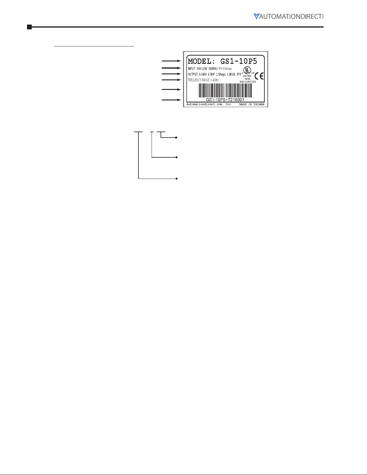
GS1 - 1 0P5
Series Name
naMePlate inforMation
Example of 0.5 hp 115 VAC drive
Output Frequency Range
Model exPlanation
AC Drive Model
Input Specification
Output Specification
Barcode
Serial Number
Applicable Motor Capacity
0P2: 1/4HP 0P5: 1/2HP
1P0: 1HP 2P0: 2HP
Input Voltage
1: 100–120VAC
2: 200–240VAC
drive Package contents
After receiving the AC motor drive, please check for the following:
•
Make sure that the package includes an AC drive and the GS1 Series AC Drive Quick Reference�
•
Inspect the unit to insure it was not damaged during shipment�
•
Make sure that the part number indicated on the nameplate corresponds with the part number of
your order�
Page 1–4 GS1 Series AC Drives User Manual – 3rd Ed., Rev.B
Page 17
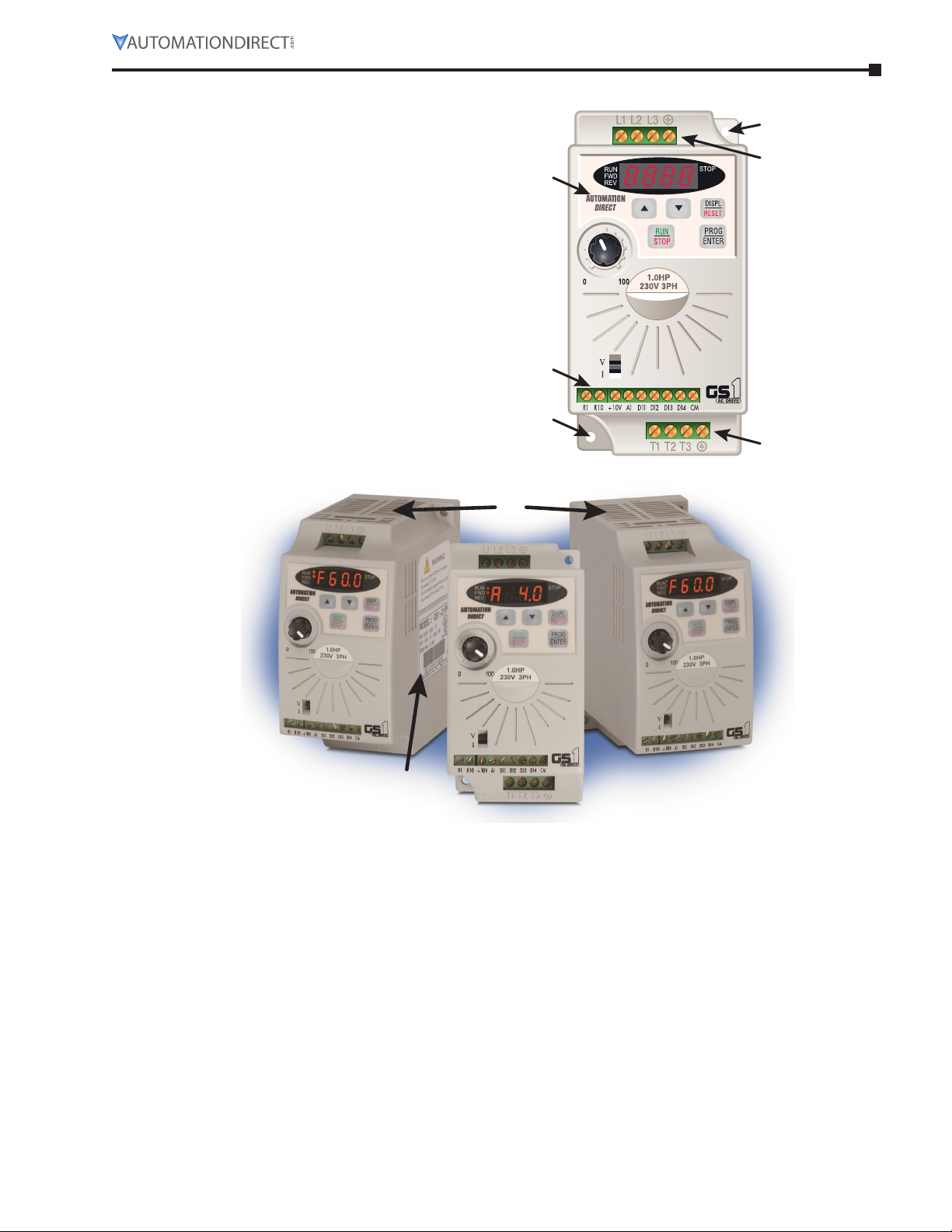
external Parts and labels
Chapter 1: Getting Started
a Digital Keypad
b Ventilation Slots
c Mounting Screw Holes
d Nameplate Label
e Input Power Terminals
f Control Input/Output Terminals
g Output Power Terminals
Page 1–5GS1 Series AC Drives User Manual – 3rd Ed., Rev.B
Page 18
Chapter 1: Getting Started
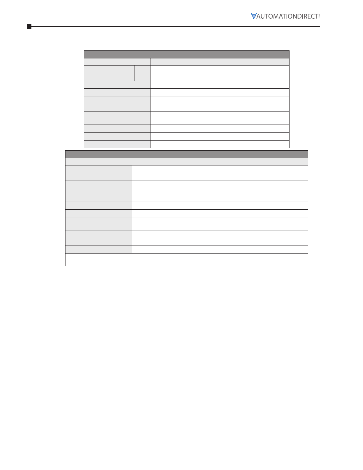
Gs1 Ac dRIVe specIfIcATIoNs
gs1 Model-sPecific sPecifications
Model Name GS1-10P2 GS1-10P5
Motor Rating
Rated Input Voltage
Maximum Output Voltage
Rated Input Current (A)
Rated Output Current (A)
Short Circuit Withstand
(A, rms symmetrical)
Watt Loss 100% I (W)
Weight (lb)
Dimensions (HxWxD)
Model Name GS1-20P2 GS1-20P5 GS1-21P0 GS1-22P0
Motor Rating
Rated Input Voltage *
Maximum Output Voltage
Rated Input Current (A)
Rated Output Current (A)
Short Circuit Withstand
(A, rms symmetrical)
Watt Loss 100% I (W)
Weight (lb)
Dimensions (HxWxD)
* All 3-phase power sources must be symmetrical. Do NOT connect GS1 drives to grounded, center-tapped,
delta transformers (which are typically used for lighting circuits).
HP
kW
115V Class GS1 Specifications
HP
kW
132�0 mm [5�20 in] x 68�0 mm [2�68 in] x 128�1 mm [5�04 in]
1/4 hp 1/2 hp
0�2 kW 0�4 kW
Single-phase: 100–120 VAC ±10%, 50/60 Hz, ±5%
Three-phase: 200–240 VAC ( x2 of input voltage)
6 9
1�6 2�5
5kA @ 120 VAC
19�2 19�2
2�16 2�24
230V Class GS1 Specifications
1/4 hp 1/2 hp 1 hp 2 hp
0�2 kW 0�4 kW 0�7 kW 1�5 kW
Single/three-phase:
200–240 VAC ±10%, 50/60 Hz ±5%
Three-phase: 200–240VAC (proportional to input voltage)
4�9/1�9 6�5/2�7 9�7/5�1 9
1�6 2�5 4�2 7�0
5kA @ 240 VAC
18�4 26�8 44�6 73
2�06 2�2 2�26 2�2
132�0 mm [5�20 in] x 68�0 mm [2�68 in] x 128�1 mm [5�04 in]
200–240VAC ±10%, 50/60Hz ±5%
Three-phase*:
Page 1–6 GS1 Series AC Drives User Manual – 3rd Ed., Rev.B
Page 19

gs1 general sPecifications
Control System
Rated Output Frequency
Output Frequency Resolution
Overload Capacity
Torque Characteristics
DC Braking
Acceleration/Deceleration Time
Voltage/Frequency Pattern
Stall Prevention Level
Frequency
Setting
Operation
Setting
Inputs
Input
Terminals
Output
Terminals
Outputs
Operating Functions
Protective Functions
Operator Devices
Operator
Interface
Environment
Programming
Status Display
Key Functions
Enclosure Rating
Ambient Temperature
Ambient Humidity
Vibration
Installation Location
Keypad
External
Signal
Keypad
External
Signal
Digital
Analog
Digital
Chapter 1: Getting Started
General Specifications
Control Characteristics
Sinusoidal Pulse Width Modulation, carrier frequency 3–10 kHz
1�0 to 400�0 Hz
0�1 Hz
150% of rated current for 1 minute
Includes auto-slip compensation and starting torque 150% @ 5�0 Hz
Operation frequency: 0 to 60 Hz, 0–30% rated voltage�
Start time 0�0–5�0 seconds� Stop time 0�0–25�0 seconds
0�1 to 600 seconds (can be set individually)
V/F pattern adjustable� Settings available for Constant Torque - low and high
starting torque, Variable Torque - low and high starting torque, and user
configured
20 to 200% or rated current
Operation Specifications
Setting by <UP> or <DOWN> buttons or potentiometer
Potentiometer-3to5kΩ,0.5W;0to10VDC(inputimpedance10kΩ);0to20
mA/4to20mA(inputimpedance250Ω);
Mu lti-function inputs 3 and 4 (3 steps, JOG, UP/DOWN command); RS-485
communication setting
Setting by <RUN>, <STOP> buttons
DI1, DI2, DI3, DI4 can be combined to offer various modes of operation, RS-485
communication port
4 user-programmable: FWD/STOP, REV/STOP, RUN/STOP, REV/FWD, RUN
momentary (N�O�), STOP momentary (N�C�), External Fault (N�O�/N�C�), External
Reset, Multi-Speed Bit (1and 2), Jog, External Base Block (N�O�/N�C�), Second
Accel/Decel Time, Speed Hold, Increase Speed, Decrease Speed, Reset Speed to
Zero, Input Disable
1 user-configurable, 10 bit resolution
0to10VAC,(inputimpedance10kΩ),
0to20mA,(inputimpedance250Ω)
4to20mA,(inputimpedance250Ω)
1 user programmable: AC drive Running, AC drive Fault, At Speed, Zero Speed,
Above Desired Frequency (P 3-16), Below Desired Frequency (P 3-16), At
Maximum Speed, Over-torque Detected, Above Desired Current (P3-17), Below
Desired Current (P 3-17)
Automatic voltage regulation, S-curve, Over-voltage stall prevention, DC braking,
Fault records, Adjustable carried frequency, Starting frequency setting of DC
braking, Over-current stall prevention, Momentary power loss restart, Reverse
inhibition, Frequency limits, Parameter lock/reset
Overcurrent, Overvoltage, Undervoltage, Electronic thermal motor overload,
Overheating, Overload, Self testing
5-key, 4-digit, 7-segment LED, 4 status LEDs, potentiometer
Parameter values for setup and review, fault codes
Master Frequency, Output Frequency, Scaled Output Frequency, Output Voltage,
DC Bus Voltage, Output Direction, Trip Event Monitor, Trip History Monitor
RUN/STOP, DISPLAY/RESET, PROGRAM/ENTER, <UP>, <DOWN>
Protected chassis, IP20
-10° to 40°C (14°F to 104°F) w/o derating
0 to 90% RH (non-condensing)
9�8 m/s2(1G), less than 10 Hz; 5�88 m/s2 (0�6G) 20 to 50 Hz
Altitude 1000m or lower above sea level, keep from corrosive gas, liquid and
dust
Page 1–7GS1 Series AC Drives User Manual – 3rd Ed., Rev.B
Page 20

Chapter 1: Getting Started
BLANK
PAG E
Page 1–8 GS1 Series AC Drives User Manual – 3rd Ed., Rev.B
Page 21

Chapter
Chapter
Chapter
InstallatIon and WIrIng
2
2
2
C
ontentS of thiS ChApter
Ambient Conditions . . . . . . . . . . . . . . . . . . . . . . . . . . . . . . . . . . . . . . . . . . .2–2
Storage Conditions . . . . . . . . . . . . . . . . . . . . . . . . . . . . . . . . . . . . . . . . . . .2–2
Installation . . . . . . . . . . . . . . . . . . . . . . . . . . . . . . . . . . . . . . . . . . . . . . . .2–3
Minimum Clearances and Air Flow . . . . . . . . . . . . . . . . . . . . . . . . . . . . . . . . . . . . . . 2–3
GS1 AC Drive Dimensions. . . . . . . . . . . . . . . . . . . . . . . . . . . . . . . . . . . . . . . .2–4
GS1 Circuit Connections . . . . . . . . . . . . . . . . . . . . . . . . . . . . . . . . . . . . . . . .2–5
Danger!. . . . . . . . . . . . . . . . . . . . . . . . . . . . . . . . . . . . . . . . . . . . . . . . . .2–5
Wiring Notes: PLEASE READ PRIOR TO INSTALLATION. . . . . . . . . . . . . . . . . . . . . . . . . . . 2–5
Motor Operation Precautions. . . . . . . . . . . . . . . . . . . . . . . . . . . . . . . . . . . . . . . . . 2–6
Short Circuit Withstand . . . . . . . . . . . . . . . . . . . . . . . . . . . . . . . . . . . . . . . . . . . . 2–6
Applicable Codes . . . . . . . . . . . . . . . . . . . . . . . . . . . . . . . . . . . . . . . . . . . . . . . 2–6
Circuit Protection Devices. . . . . . . . . . . . . . . . . . . . . . . . . . . . . . . . . . . . . . . .2–6
Maximum Recommended Circuit Protection Devices . . . . . . . . . . . . . . . . . . . . . . . . . . . 2–6
Main Circuit Wiring . . . . . . . . . . . . . . . . . . . . . . . . . . . . . . . . . . . . . . . . . . .2–7
Input Power Connections . . . . . . . . . . . . . . . . . . . . . . . . . . . . . . . . . . . . . . . . . . . 2–7
Output Power Connections . . . . . . . . . . . . . . . . . . . . . . . . . . . . . . . . . . . . . . . . . . 2–8
Control Terminal Wiring. . . . . . . . . . . . . . . . . . . . . . . . . . . . . . . . . . . . . . . . .2–8
Basic Wiring Diagram . . . . . . . . . . . . . . . . . . . . . . . . . . . . . . . . . . . . . . . . . .2–9
External Wiring and Accessories . . . . . . . . . . . . . . . . . . . . . . . . . . . . . . . . . . . 2–10
Page 2–1GS1 Series AC Drives User Manual – 3rd Ed., Rev.B
Page 22

Chapter 2: Installation and Wiring
AmbIeNT coNdITIoNs
Ambient environmental conditions for use:
Ambient Temperature
Storage Temperature
Relative Humidity
Atmosphere Pressure
Vibration
Installation Location
Enclosure Rating
-10° to 40°C (14°F to 104°F) w/o derating
-20° to 60° C (-4°F to 140°F) during short-term transportation period)
0 to 90% RH (non-condensing)
86 kPA to 106 kPA
9.8 m/s2(1G) @ less than 10 Hz; 5.88 m/s2 (0.6G) @ 10 to 50 Hz
Altitude 1000m or lower above sea level, keep from corrosive gas, liquid and dust
Protected chassis, IP20
sToRAGe coNdITIoNs
GS1 AC drives should be kept in their shipping carton or crate until they are installed. In order to retain
their warranty coverage, they should be stored as described below if they are not to be installed and used
within three months.
•
Store in a clean and dry location free from direct sunlight and corrosive fumes.
•
For storage of longer than 3 months, store within an ambient temperature range of -20°C to 30°C
(-4°F to 86°F).
•
For storage of 3 months or less, store within an ambient temperature range of -20°C to 60°C (-4°F
to 140°F).
•
Store within a relative humidity range of 0% to 90% and non-condensing environment.
•
Store within an air pressure range of 86 kPA to 106 kPA.
•
DO NOT store in an area with rapid changes in temperature. (It may cause condensation and
frost.)
•
DO NOT place directly on the ground.
Ambient Conditions
NOTE: If the drive is stored or is otherwise unused for more than a year, the drive’s internal DC link
capacitors should be recharged before use. Otherwise, the capacitors may be damaged when the drive starts
to operate. We recommend recharging the capacitors of any unused drive at least once per year. (Refer to
Chapter 6, “Maintenance and Troubleshooting” for information about recharging DC link capacitors.)
Page 2–2 GS1 Series AC Drives User Manual – 3rd Ed., Rev.B
Page 23
INsTAllATIoN
Fan
Motor
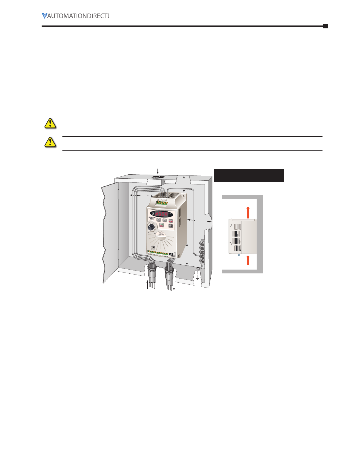
Install the AC drive in an enclosure that is specifically designed to house electrical and electronic control
equipment. Provide proper spacing within the enclosure to allow the dissipation of heat produced by the
drive and any other included electrical and electronic equipment. Ventilation or air conditioning may also
be required, depending upon the application.
Improper installation of the AC drive will greatly reduce its life. Be sure to observe the following
precautions when selecting a mounting location:
•
Do not mount the AC drive near heat-radiating elements or in direct sunlight.
•
Do not install the AC drive in a place subjected to high temperature, high humidity, excessive
vibration, corrosive gases or liquids, or airborne dust or metallic particles.
•
Mount the AC drive vertically and do not restrict the air flow to the heat sink fins.
Warning: failure to observe these preCautions may damage the drive and void the Warranty!
Warning: aC drives generate a large amount of heat WhiCh may damage the aC drive. auxiliary Cooling
methods are typiCally required in order not to exCeed maximum ambient temperatures.
MiniMuM clearances and air flow
2 in
[50mm]
min.
6 in [150mm] min.
[50mm]
Chapter 2: Installation and Wiring
MaxiMuM aMbient teMperatures
Must not exceed 40°c (104°F)!
Air Flow
2 in
min.
Input
Power
6 in
[150mm]
min.
To
Page 2–3GS1 Series AC Drives User Manual – 3rd Ed., Rev.B
Page 24
Chapter 2: Installation and Wiring
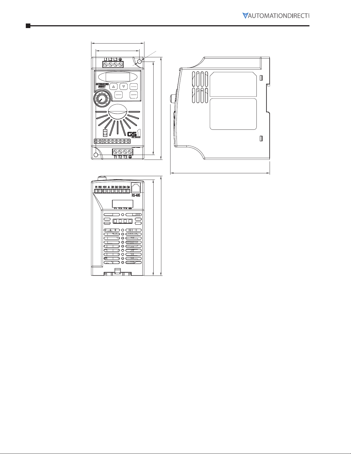
68.0 (2.68)
Gs1 Ac dRIVe dImeNsIoNs
56.0 (2.20)
dia. 5.0 (0.20)
RUN
STOP
DI4AIR1OR1 +10V DI2DI1DI3 CM
STOP
DISPL
RESET
PROG
ENTER
120.0 (4.72)
132.0 (5.20)
RUN
FWD
REV
1000
V
I
128.1 (5.04)
123.4 (4.86)
128.1 (5.04)
Unit: mm (in)
Page 2–4 GS1 Series AC Drives User Manual – 3rd Ed., Rev.B
Page 25
Gs1 cIRcuIT coNNecTIoNs
running
dANGeR!
hazardous voltage! before making any ConneCtion to the aC drive, disConneCt all poWer to the aC
drive, and Wait five minutes for dC bus CapaCitors to disCharge.
Warning: any eleCtriCal or meChaniCal modifiCation to this equipment Without prior Written Consent
of automationdireCt.Com inC. Will void all Warranties, may result in a safety hazard, and may void the
ul listing.
wiring notes: Please read Prior to installation.
Warning: do not ConneCt the aC input poWer to the t1, t2, and t3 output terminals. this Will
damage the aC drive.
Warning: tighten all sCreWs to the proper torque rating. see “main CirCuit Wiring” later in this
Chapter.
1) During installation, follow all local electrical, construction, and safety codes for the country in which
the AC drive is to be installed.
2) Make sure the appropriate protective devices (circuit breaker or fuses) are connected between the
power supply and AC drive.
3) Make sure that the leads are connected correctly and the AC drive is properly grounded.
4) Use ground leads that comply with AWG/MCM standards, and keep them as short as possible.
5) The use of contactors or disconnect switches for run/stop control of the AC drive and motor will
reduce the operating life cycle of the AC drive.
Cycling a power circuit switching device while the AC drive is in run mode should be done only in
emergency situations.
The installation of contactors or disconnects to isolate the motor during maintenance, though
permissible, is not recommended. Opening contactors or disconnects while the drive is running will
reduce the life cycle of the drive and may immediately damage the inverter section of the drive!
6) Multiple GS1 units can be installed in one location. All the units should be grounded directly to a
common ground terminal. The GS1 ground terminals may also be connected in parallel, as shown
in the figure below. Make sure there are no ground loops.
Chapter 2: Installation and Wiring
Correct Incorrect
Forward
7) When the AC drive output terminals T1, T2, and T3 are connected to the motor terminals T1, T2, and
T3, respectively, the motor will rotate counterclockwise (as viewed from the shaft end of the motor)
when a forward operation command is received. To reverse the direction of motor rotation, switch
the connections of any of the two motor leads.
8) Make sure that the power source is capable of supplying the correct voltage and required current to
the AC drive.
9) Do not attach or remove wiring when power is applied to the AC drive.
10) Do not monitor the signals on the circuit board while the AC drive is in operation.
11) For single-phase, 115V class AC drives, AC power must be connected to terminals L1 and L2. For the
single-phase, 230V class AC drives, the AC power can be connected to any two of the three input
terminals L1, L2, or L3.
NOTE: This AC drive is not intended for use with single-phase motors.
12) Route the power and control wires separately, or at 90 degree angle to each other.
13) When using a GFCI (Ground Fault Circuit Interrupt), select current sensor with sensitivity of 200mA,
and not less than 0.1-second detection to avoid nuisance tripping.
Page 2–5GS1 Series AC Drives User Manual – 3rd Ed., Rev.B
Page 26

Chapter 2: Installation and Wiring
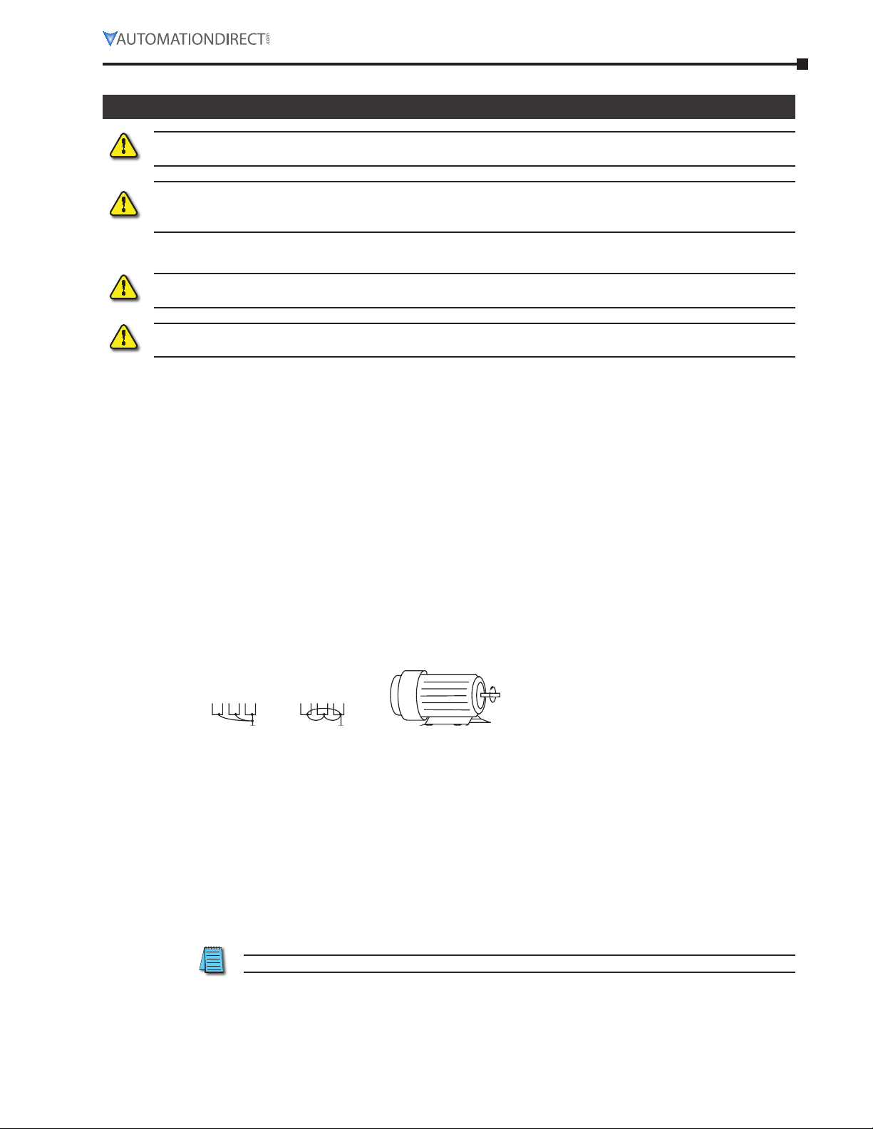
Motor oPeration Precautions
1) When using the AC drive to operate a standard 3-phase induction motor, the energy loss is greater
than for an inverter duty motor.
2) Avoid running a standard induction motor at low speed, which may cause the motor temperature to
exceed the motor rating due to limited airflow produced by the motor’s fan.
3) When the standard motor operates at low speed, the output load must be decreased.
4) If 100% output torque is desired at low speed, it may be necessary to use a special “inverter-duty”
rated motor.
short circuit withstand
Suitable for use on a circuit capable of delivering not more than 5,000 rms symmetrical amperes.
•
For all 115V models, the maximum is 120 Volts.
•
For all 230V Models, the maximum is 240 Volts.
aPPlicable codes
All GS1 Series AC drives are Underwriters Laboratories, Inc. (UL) and Canadian Underwriters Laboratories
(cUL) listed, and therefore comply with the requirements of the National Electrical Code (NEC) and the
Canadian Electrical Code (CEC).
Installation intended to meet the UL and cUL requirements must follow the instructions provided in
“Wiring Notes” as a minimum standard. Follow all local codes that exceed UL and cUL requirements. Refer
to the technical data label affixed to the AC drive and the motor nameplate for electrical data.
The “Fuses and Fuse Kits” section in Appendix A lists the recommended fuse part number for each GS1
Series part number. These fuses (or equivalent) must be used on all installations where compliance with
U.L. standards is required.
cIRcuIT pRoTecTIoN deVIces
Short-circuit and ground-fault protection devices are essential to prevent costly damage to your AC Drive.
Fuse kits, which include fuses and fuse blocks, are available from AutomationDirect for the GS1 Series AC
Drives.
MaxiMuM recoMMended circuit Protection devices
The chart below gives the maximum recommended fuses and circuit breakers for short-circuit and
ground-fault protection of GS1 Series AC Drives. Fuses and circuit breakers smaller than those shown are
permitted.
Maximum Recommended Circuit Protection Devices
Drive
Part #
GS1-10P2 115 / 0.25 / 0.2 1 6A 20A type A3T (300V) 20A
GS1-10P5 115 / 0.5 / 0.4 1 9A 30A type A3T (300V) 30A
GS1-20P2 230 / 0.25 / 0.2
GS1-20P5 230 / 0.5 / 0.4
GS1-21P0 230 / 1 / 0.7
GS1-22P0 230 / 2 / 1.5 3 9.0A 25A type A3T (300V) 25A
Re commended fuses are required for UL applications, and the specific fuses are available as
shown in “Appendix A: Accessories”.
Re commended maximum fuses and circuit breakers are for protection of the AC drive.
They may or may not also provide required motor branch circuit protection, depending upon
the electrical code applicable to the installation.
V/HP/kW
Input
Phases
1 4.9A 15A type A3T (300V) 15A
3 1.9A 10A type A3T (300V) 10A
1 6.5A 25A type A3T (300V) 25A
3 2.7A 10A type A3T (300V) 10A
1 9.7A 45A type A3T (300V) 45A
3 5.1A 20A type A3T (300V) 20A
Input
Current
Fuse
Inverse-Time
Circuit Breaker
Page 2–6 GS1 Series AC Drives User Manual – 3rd Ed., Rev.B
Page 27
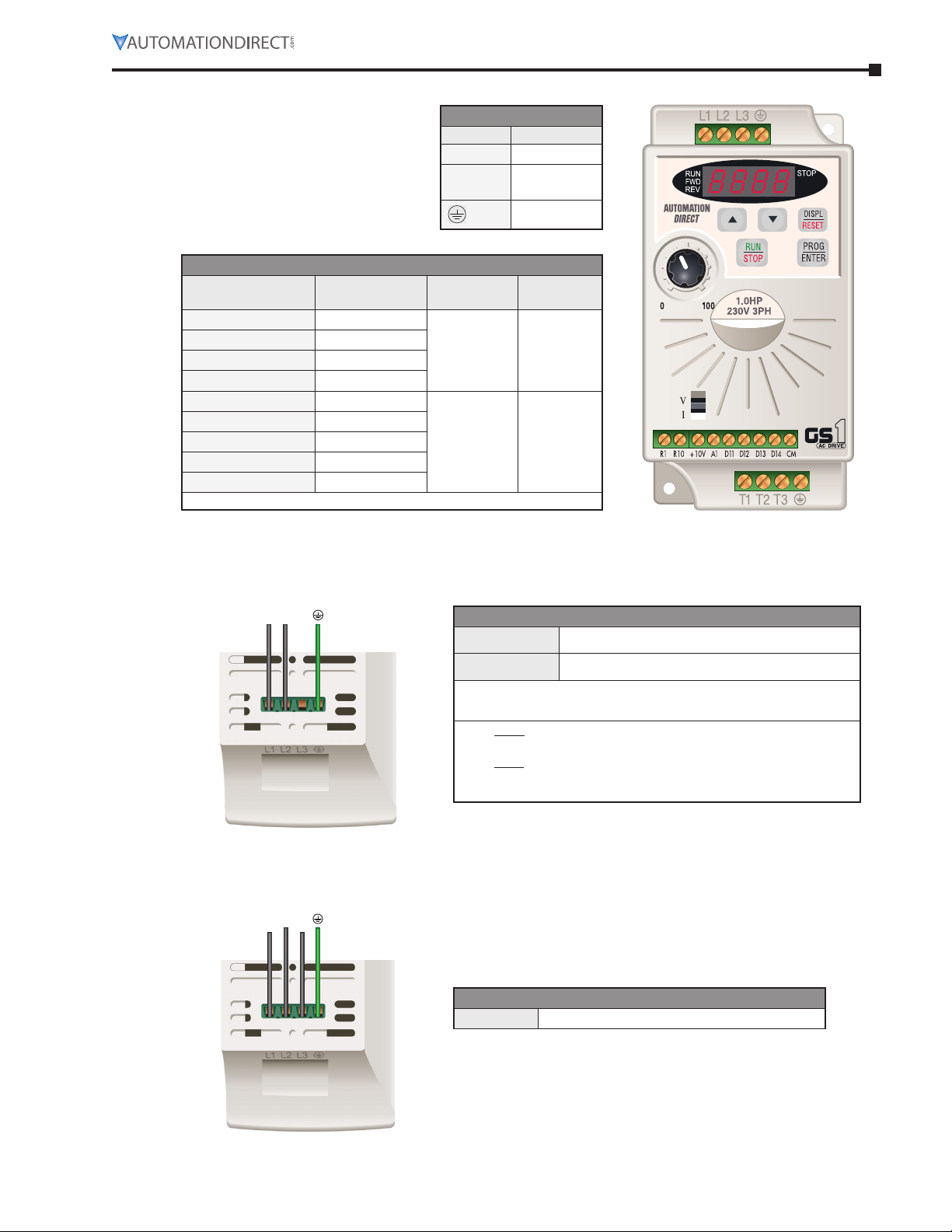
mAIN cIRcuIT WIRING
Main Circuit Wiring Specifications
AC Drive Model
GS1-10P2 6A / 1.6A
GS1-10P5 9A / 2.5A
GS1-20P2 (1-phase) 4.9A / 1.6A
GS1-20P2 (3-phase) 1.9A / 1.6A
GS1-20P5 (1-phase) 6.5A / 2.5A
GS1-20P5 (3-phase) 2.7A / 2.5A
GS1-21P0 (1-phase) 9.7A / 4.2A
GS1-21P0 (3-phase) 5.1A / 4.2A
GS1-22P0 9A / 7.0A
Wire Type: 75°C, copper only
Max. Current
(Input/Output)
Main Circuit Terminals
Terminal Description
L1, L2, L3 Input Power
T1, T2, T3
Wire Gauge Torque
12–16 AWG 5.5 kgf·cm
12–14 AWG 5.5 kgf·cm
AC Drive
Output
Ground
Chapter 2: Installation and Wiring
inPut Power connections
1-Phase inPut Power connections* **
GS1 Top View (input power terminals)
L1 L2
3-Phase inPut Power connections
GS1 Top View (input power terminals)
L1L2L3
1-Phase Input Power*
115V Class**
230V Class**
* Only models GS1-10P2, GS1-10P5, GS1-20P2, GS1-20P5,
and GS1-21P0 are rated for single-phase input power.
** For 115V class single phase drives,
AC power must be connected to terminals L1 and L2.
For 230V class single phase drives,
AC power can be connected to any two of the three terminals L1,
L2 or L3.
Single-phase: 100–120VAC ± 10%, 50/60Hz, ±5%
Single-phase: 200–240VAC ± 10%, 50/60Hz ±5%
230V Class
3-Phase Input Power
Three-phase: 200–240VAC ±10%, 50/60Hz ±5%
Page 2–7GS1 Series AC Drives User Manual – 3rd Ed., Rev.B
Page 28
Chapter 2: Installation and Wiring
outPut Power connections
GS1 Bottom View
(output power terminals)
T1 T2 T3
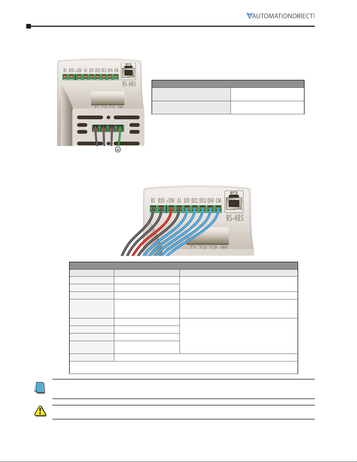
coNTRol TeRmINAl WIRING
Output Power
115V Class Max Output Voltage
230V Class Max Output Voltage
GS1 Bottom View (control terminals)
Three phase 200–240VAC
(input voltage x2)
Three phase 200–240VAC
(proportional to input voltage)
Control Circuit Terminals
Terminal Symbol Description Remarks
R1 Relay Output Common
R1O Relay Output Normally Open
+10V Internal Power Supply +10VDC (10mA maximum load)
AI Analog Input
DI1 Digital Input 1 Input voltage: Internally supplied (see Warning below)
DI2 Digital Input 2
DI3 Digital Input 3
DI4 Digital Input 4
CM Common
Control Terminal Wire Range: 24–12 AWG
Control Terminal Tightening Torque: 5kgf·cm [4lbf·in]
120VAC/24VDC @5A; 230VAC @2.5A
0 to +10 V (Max. Output Frequency) Input
0 to 20mA (Max. Output Frequency) Input
4 to 20mA (Max, Output Frequency) Input
Maximum ON Voltage: 6V
Minimum OFF Voltage: 11V
Minimum ON Current: 2.5 mA
Maximum OFF Current: 1mA
(See “Basic Wiring Diagram” on next page.)
NOTE: Use twisted-shielded, twisted-pair or shielded-lead wires for the control signal wiring. Run all signal
wiring in a separate steel conduit. The shield wire should only be connected at the AC drive. Do not connect
shield wire on both ends.
Warning:
do not ConneCt external voltage sourCes to the digital inputs. permanent damage may result.
Page 2–8 GS1 Series AC Drives User Manual – 3rd Ed., Rev.B
Page 29
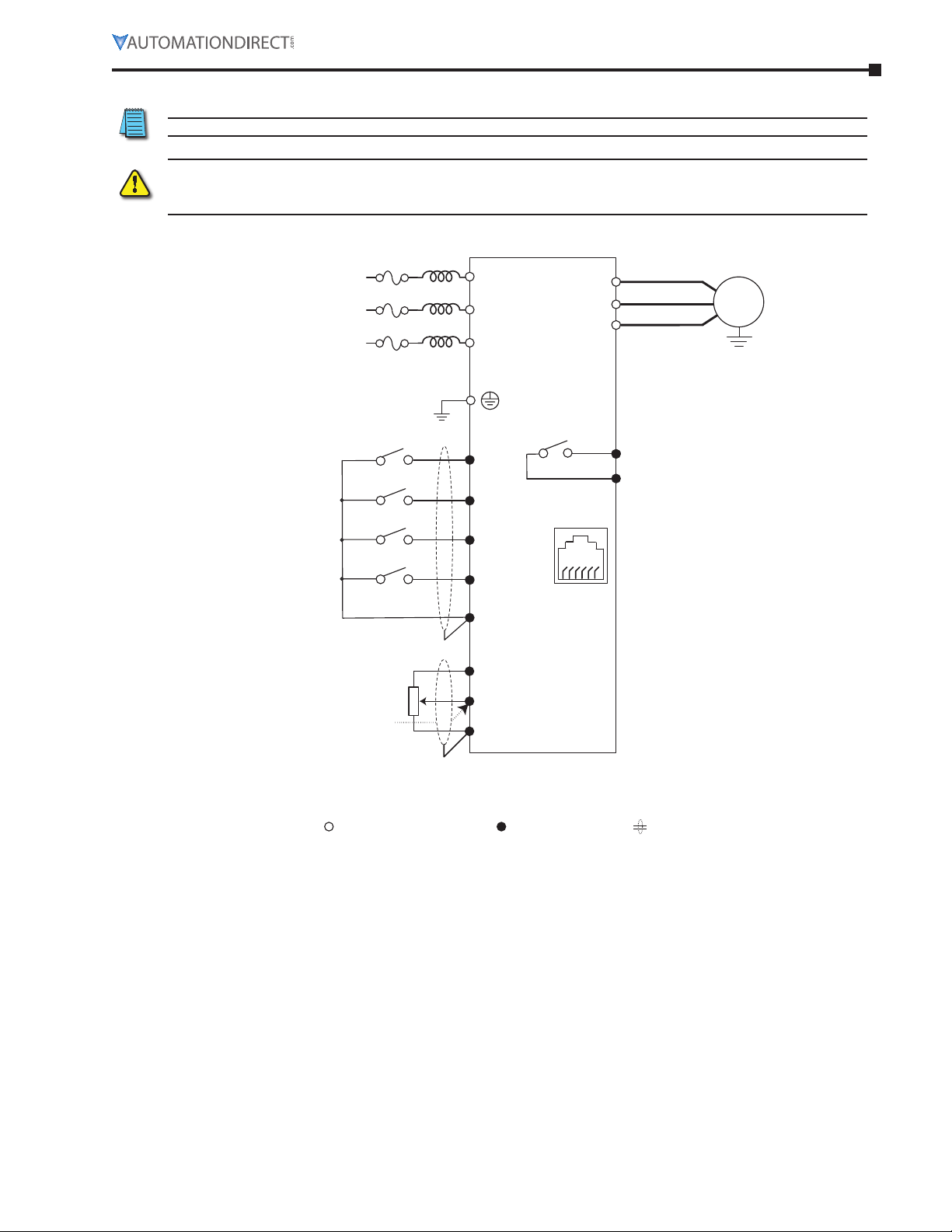
bAsIc WIRING dIAGRAm
Control circuit terminal Shielded leadsMain circuit (power) terminals
Multi-function output contacts
Power Source 3-phase*
NOTE: Users must connect wiring according to the circuit diagram shown below.
Warning: do not plug a modem or telephone into the gs1 rj-12 serial Comm port, or permanent
damage may result. terminals 1 and 2 must not be used as a poWer sourCe for your CommuniCation
ConneCtion.
Chapter 2: Installation and Wiring
100–120V±10%
(50/60Hz ±5%)
200–240V±10%
(50/60Hz±5%)
* Use terminals L1 and L2 for 115V, or
select any two of the power terminals
for 230V single-phase models
Grounding resistance
less than 0.1
Forward/Stop
Reverse/Stop
External Fault (NO)
Jog
Common Signal
Analog voltage
0–10VDC
Potentiometer
3–5k
Analog current
0–20mA; 4–20mA
L1
GS1-xxxx
L2
L3
DI1
DI2
DI3
DI4
Communication
CM
+10V 10mA
(max)
AI
CM
T1
T2
T3
R1O
R1
RJ-12 (6P6C)
16
Port
AC Motor
IM
120VAC/24VDC @5A
230VAC @2.5A
AC Drive Running
RJ-12 Serial Comm Port
RS-485
1: +17V
2: GND
3: SG4: SG+
5: +5V
Factory default setting
Factory default source of frequency command is via the keypad potentiometer
Page 2–9GS1 Series AC Drives User Manual – 3rd Ed., Rev.B
Page 30
Chapter 2: Installation and Wiring
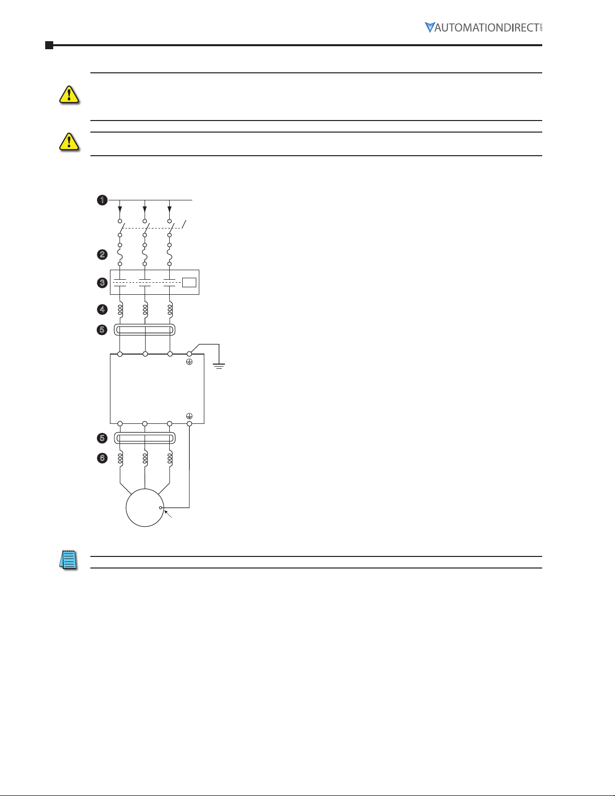
exTeRNAl WIRING ANd AccessoRIes
Warning: the installation of ContaCtors or disConneCts to isolate the motor during maintenanCe,
though permissible, is not reCommended. opening ContaCtors or disConneCts While the drive is
running Will reduCe the life CyCle of the drive and may immediately damage the inverter seCtion of the
drive!
Warning: We strongly reCommend that you do not use a ContaCtor betWeen the aC drive and the
motor, unless there is an interloCk to open the ContaCtor When the drive is not running.
From power supply
1
Disconnect
Switch
2
3
4
5
L1L3L2
GS1-xxxx
AC Drive
T1
5
6
Motor
T3T2
Motor grounding
terminal
1 Power Supply
Please follow the specific power supply requirements shown in
Chapter 1.
2 Fuses
Input fuses protect the AC drive from excessive input current
due to line surges, short circuits, and ground faults. They are
recommended for all installations and may be required for
UL-listed installations.
3 Contactor (Optional)
Do NOT use a contactor or disconnect switch for run/stop control
of the AC drive and motor. This will reduce the operating life
cycle of the AC drive. Cycling a power circuit switching device
while the AC drive is in run mode should be done only in
emergency situations.
4 AC Line Reactor – Input Side (Optional)
Input line reactors protect the AC drive from transient
overvoltage conditions typically caused by utility capacitor
switching. Input line reactors also reduce harmonics associated
with AC drives, and are recommended for all installations.
5 RF Filter (Optional)
RF filters reduce the radio frequency interference or noise on the
input or output side of the inverter.
6 AC Line Reactor – Output Side (Optional)
Output line (load) reactors protect the motor insulation against
AC drive short circuits and IGBT reflective wave damage, and also
“smooth” the motor current waveform, allowing the motor to
run cooler. They are recommended for operating “non-inverter-
duty” motors, and when the length of wiring between the AC
drive and motor exceeds 75ft.
Please refer to Appendix A for specifications on GS1 AC Drive Accessories.
Page 2–10 GS1 Series AC Drives User Manual – 3rd Ed., Rev.B
Page 31

chapter
chapter
chapter
Keypad OperatiOn and QuicK-Start
3
3
3
C
ontentS of thiS ChApter
The GS1 Digital Keypad . . . . . . . . . . . . . . . . . . . . . . . . . . . . . . . . . . . . . . . . .3–2
LED Display. . . . . . . . . . . . . . . . . . . . . . . . . . . . . . . . . . . . . . . . . . . . . . . . . . . 3–2
Function Keys . . . . . . . . . . . . . . . . . . . . . . . . . . . . . . . . . . . . . . . . . . . . . . . . . 3–2
Displaying the Status of the GS1 AC Drive. . . . . . . . . . . . . . . . . . . . . . . . . . . . . . . . . . 3–3
Programming the GS1 AC Drive . . . . . . . . . . . . . . . . . . . . . . . . . . . . . . . . . . . . . . . 3–4
GS1 Quickstart . . . . . . . . . . . . . . . . . . . . . . . . . . . . . . . . . . . . . . . . . . . . . .3–5
Example 1: Constant torque (e.g. conveyors, compressors, etc.). . . . . . . . . . . . . . . . . . . . . . 3–5
Example 2: Variable torque (e.g. fans, centrifugal pumps, etc.) . . . . . . . . . . . . . . . . . . . . . . 3–8
Page 3–1GS1 Series AC Drives User Manual – 3rd Ed., Rev.B
Page 32

Chapter 3: Keypad Operation and Quick-Start
The Gs1 dIGITAl keypAd
The digital keypad includes a 4-digit LED display, 4 LED indicators, 5 function keys, and a potentiometer.
The diagram below shows all of the features of the digital keypad and an overview of their functions.
LED Display with
RUN, FWD, REV, STOP
indicators
Up Key
Down Key
Display/Reset Key
Program/Enter Key
Potentiometer
RUN/STOP Key
led disPlay
The LED Display shows the operation values and parameter settings of the AC drive. The display also has
four LED Indicators that show the RUN, STOP, FWD, and REV status of the AC drive.
A solid RUN LED and blinking STOP LED indicate an active RUN command with a speed reference of
zero hertz.
function keys
Program/Enter Key
Press the PROGRAM/ENTER key to view parameters and store parameter settings.
Display/Reset Key
Press the DISPL/RESET key to cycle through the operational values (Status Display) of
the AC drive. This key will also reset the AC drive when a fault has occurred.
Run/Stop Key
Press the RUN/STOP key to start or stop the AC drive operation.
Up/Down Keys
Press the UP/DOWN keys to scroll through the parameter set or to change parameter
settings. Press the “Up” or “Down” key momentarily to change the parameter settings in
single-unit increments. To quickly run through the range of settings, press and hold the
“Up” or “Down” key.
Potentiometer
The potentiometer is used to set the AC drive operation frequency.
Page 3–2 GS1 Series AC Drives User Manual – 3rd Ed., Rev.B
Page 33

Chapter 3: Keypad Operation and Quick-Start
disPlaying the status of the gs1 ac drive
Press the DISPL/RESET button on the keypad repeatedly to cycle through the status messages on the AC
drive. The diagram below shows the order of the status messages and their definitions. The status of the
AC drive can be shown in RUN or STOP mode.
↓
0
1
2
3
4
5
6
K60.0
↓
1750
↓
90.0
↓
A 0.9
↓
o18.0
↓
U230
↓
d328
Actual Operating Frequency
0
Displays the actual operating frequency present at the T1, T2, and T3 terminals. Example: 60.0Hz
RPM
1
Displays the present estimated speed of the motor. Example: 1750 rpm
Scaled Frequency
2
Displays the result of output frequency x P8.01. Example: 60Hz x 1.5 = 90.0
Amps
3
Displays the output current present at the T1, T2, and T3 terminals. Example: 0.9A
% Load
4
Displays the amount of load on the AC drive. Example: (Output Current ÷ Drive Rated Current) x 100
Output Voltage
5
Displays the output voltage present at the T1, T2, and T3 terminals. Example: 230V
DC Bus Voltage
6
Displays the DC Bus Voltage. Example: 328 VDC
7
↓
F60.0
Setpoint Frequency
7
Displays the frequency setting of the AC drive. Example: 60.0 Hz
Page 3–3GS1 Series AC Drives User Manual – 3rd Ed., Rev.B
Page 34

Chapter 3: Keypad Operation and Quick-Start
PrograMMing the gs1 ac drive
The GS1 AC Drive parameters are organized into 10 different groups according to their functions. The
illustration below shows you how to navigate through the parameter groups and parameter settings. For a
complete list of parameters, see Chapter 4.
1
2
Program
Mode
Select
Parameter
Group
0-
1-
2-
1 Press the PROG/ENTER key to enter program mode. Only the parameter
groups will be displayed.
2 Use the UP/DOWN keys to cycle through the available parameter groups.
Press the PROG/ENTER key to select the desired parameter group.
3 Use the UP/DOWN keys to cycle through the parameters in the selected
parameter group.
4 When you reach your desired parameter, press the PROG/ENTER key to
select the parameter.
5 Use the UP/DOWN keys to select the desired parameter setting.
6 Press the PROG/ENTER key to store the parameter setting into memory.
“End” will display on the digital display to signal that the parameter value
has been changed.
7 After the parameter value has been set, the AC drive will cycle to the next
parameter in the selected group. Repeat steps 3 through 6 to change
another parameter setting.
8 Press the DISPL/RESET key if you need to change from the parameter
selection menu to the parameter group menu.
3-
Select
3
Parameter
4- 0-00
5- 0-01
5
6- 0-02 50
4
Select
Parameter
Value
6
8- 0-03 60
9-
8
0-04 400 End
7
Page 3–4 GS1 Series AC Drives User Manual – 3rd Ed., Rev.B
Page 35

Chapter 3: Keypad Operation and Quick-Start
Gs1 quIcksTART
The following examples will help you quickly set up your GS1 AC Drive for two common applications. The
first example applies to an application that requires constant torque, and the second example requires
variable torque in its application.
For a complete list and description of the parameters for the GS1 Series AC drives, refer to Chapter 4, AC
Drive Parameters.
exaMPle 1: constant torque (e.g. conveyors, coMPressors, etc.)
In this example, the AC drive needs to operate a motor that is connected to a conveyor. In order to decide
which parameters need modifications, we will make a list of the needs for the application.
aPPlication needs
•
The AC drive must control a 230V, 1hp motor. The AC drive model that we will use for this
application is a GS1-21P0. An example of the motor nameplate is shown below.
INVeRTeR duTy moToR
hp 1 VolTs 230 phAse 3 Type p
Rpm 1725 Amps 4.2 hZ 60 sf 1.15
desIGN b Amb 40°c INsul clAss f
duTy coNT eNcl Tefc code k
•
The maximum speed for the motor is 2000 rpm.
•
The motor should accelerate to maximum speed in 5 seconds.
•
The motor should decelerate from maximum speed in 5 seconds.
•
The motor will require a high torque when starting.
•
The operation of the motor (start, stop, etc.) will be controlled by external control terminals. All
keys on the GS1 keypad should be disabled.
•
The frequency of the AC drive will be determined by a remote potentiometer that provides a 0 to
+10V signal.
•
The display of the AC drive should show the motor speed (rpm) when running.
Page 3–5GS1 Series AC Drives User Manual – 3rd Ed., Rev.B
Page 36

Chapter 3: Keypad Operation and Quick-Start
ParaMeter setuP (for exaMPle 1)
In order to meet the needs of this application, the parameters should be set as follows:
P0.00 Motor Nameplate Voltage Setting: 230
Range: 200V series: 200/208/220/230/240 Default: 240
This parameter setting is determined by the motor nameplate data.
P0.01 Motor Nameplate Amps Setting: 4.2
Range: Drive Rated Amps x 0.3 to Drive Rated Amps x 1.0
This parameter setting is determined by the motor nameplate data.
P0.02 Motor Base Frequency Setting: 60
Range: 50/60/400 Default: 60
This parameter setting is determined by the motor nameplate data.
P0.03 Motor Base RPM Setting: 1725
Range: 375 to 9999 rpm Default: 1750
This parameter setting is determined by the motor nameplate data.
P0.04 Motor Maximum RPM Setting: 2000
Range: P0.03 to 9999 rpm Default: P0.03
This parameter setting is determined by the needs of the application.
Default: Drive Rating (A)
Warning: the motor maximum rpm parameter (p0.04) should never exCeed the maximum rpm
rating for the motor you are using. if this information is not readily available, Consult your motor
manufaCturer.
P1.00 Stop Methods Setting: 0
Range: 0 – Ramp to Stop
1 – Coast to stop
Default: 0
The application requires that this parameter be set to Ramp to Stop because the motor needs to stop
under power. If the AC drive was set for Coast to Stop, the AC drive would ignore the Deceleration Time
setting.
Warning: if the stop method for the gs1 aC drive is set for Coast to stop, the aC drive Will ignore
any setting you have for deCeleration time (p1.02).
P1.01 Acceleration Time Setting: 5.0
Range: 0.1 to 600 sec Default: 10 sec
The motor should accelerate from 0 rpm to Base RPM (P0.03) in 5 seconds.
P1.02 Deceleration Time Setting: 5.0
Range: 0.1 to 600 sec Default: 30 sec
The motor should decelerate from Maximum RPM (P0.04) to 0 rpm in 5 seconds.
P2.00 Volts/Hertz Settings Setting: 1
Settings: 0 – General Purpose
1 – High Starting Torque
2 – Fans and Pumps
3 – Custom
Default: 0
The GS1 Series AC drive has some predefined torque settings that meet the needs of most applications. A
custom setting is available if needed. In this example, the application requires a high starting torque.
Page 3–6 GS1 Series AC Drives User Manual – 3rd Ed., Rev.B
Page 37

Chapter 3: Keypad Operation and Quick-Start
P3.00 Source of Operation Command Setting: 2
Settings:
0 – Operation Determined by Digital Keypad.
1 – Operation determined by external control terminals. Keypad STOP is enabled.
2 – Operation determined by external control terminals. Keypad STOP is disabled.
3 – Operation determined by RS-485 interface. Keypad STOP is enabled.
4 – Operation determined by RS-485 interface. Keypad STOP is disabled.
The AC drive operation will be determined by external control terminals and the keypad stop will be
disabled.
P4.00 Source of Frequency Command Setting: 2
Settings:
0 – Frequency determined by keypad potentiometer.
1 – Frequency determined by digital keypad up/down.
2 – Frequency determined by 0 to +10V input on AI terminal. AI switch must be set to “V.”
AI switch must be set to “V” in order to use 0 to +10V input.
←
3 – Frequency determined by 4 to 20mA input on AI terminal. AI switch must be set to “I.”
4 – Frequency determined by 0 to 20mA input on AI terminal. AI switch must be set to “I.”
5 – Frequency determined by RS-485 communication interface.
The frequency of the AC drive will be determined by an external potentiometer with a 0 to +10V signal.
Default: 0
Default: 0
When configured for “Frequency determined by digital keypad Up/Down, the drive will reset the
commanded frequency to zero hertz on a power cycle. This happens only if the drive faults when it
powers down (if its running when it loses power). If the drive is stopped when it loses power (and
doesn’t trigger a Low Voltage Fault), the drive will retain the last set speed when powered back up.
P8.00 User Defined Display Function Setting: 1
Settings:
0 – Output Frequency (Hz)
1 – Motor Speed (rpm)
2 – Output Frequency x P8.01
3 – Output Current (A)
4 – Motor Output Current (%)
5 – Output Voltage (V)
6 – DC Bus Voltage (V)
9 – Frequency Setpoint
Default: 0
The AC drive display will show motor speed (rpm) when running.
Page 3–7GS1 Series AC Drives User Manual – 3rd Ed., Rev.B
Page 38

Chapter 3: Keypad Operation and Quick-Start
exaMPle 2: variable torque (e.g. fans, centrifugal PuMPs, etc.)
In this example, the AC drive needs to operate a motor that is connected to a centrifugal pump. As in
Example 1, we will make a list of the needs for the application in order to decide which parameters need
modifications.
aPPlication needs
•
The AC drive must control a 208V, 1/2hp motor. The AC drive model we will be use for this
application is a GS1-20P5. An example of the motor nameplate is shown below.
INVeRTeR duTy moToR
hp 0.5 VolTs 208 phAse 3 Type p
Rpm 3525 Amps 2.5 hZ 60 sf 1.15
desIGN b Amb 40°c INsul clAss f
duTy coNT eNcl Tefc code k
•
The maximum speed for the motor is 3600 rpm.
•
The motor should accelerate to maximum speed in 20 seconds.
•
The motor should coast to stop when operation is terminated.
•
The motor will be turning a centrifugal pump.
•
The operation of the motor (start, stop, etc.) will be controlled by the GS1 digital keypad.
•
The frequency of the AC drive will be determined by the GS1 keypad potentiometer.
•
The display of the AC drive should show output current (A) when running.
ParaMeter setuP (for exaMPle 2)
In order to meet the needs of this application, the parameters should be set as follows:
P0.00 Motor Nameplate Voltage Setting: 208
Range: 200V series: 200/208/220/230/240 Default: 240
This parameter setting is determined by the motor nameplate.
P0.01 Motor Nameplate Amps Setting: 2.5
Range: Drive Rated Amps x 0.3 to Drive Rated Amps x 1.0 Default: Drive Rating (A)
This parameter setting is determined by the motor nameplate.
P0.02 Motor Base Frequency Setting: 60
Range: 50/60/400 Default: 60
This parameter setting is determined by the motor nameplate data.
P0.03 Motor Base RPM Setting: 3525
Range: 375 to 9999 rpm Default: 1750
This parameter setting is determined by the motor nameplate data.
P0.04 Motor Maximum RPM Setting: 3600
Range: P0.03 to 9999 rpm Default: P0.03
This parameter setting is determined by the needs of the application.
Warning: the motor maximum rpm parameter (p0.04) should never exCeed the maximum rpm rating for
the motor you are using. if this information is not readily available, Consult your motor manufaCturer.
P1.00 Stop Methods Setting: 1
Settings: 0 – Ramp to Stop
1 – Coast to stop
Default: 0
The application requires that this parameter be set to Coast to Stop.
Warning: if the stop method for the gs1 aC drive is set for Coast to stop, the aC drive Will ignore
any setting you have for deCeleration time (p1.02).
Page 3–8 GS1 Series AC Drives User Manual – 3rd Ed., Rev.B
Page 39

Chapter 3: Keypad Operation and Quick-Start
P1.01 Acceleration Time Setting: 20.0
Range: 0.1 to 600 sec Default: 10 sec
The motor should accelerate from 0 rpm to Base RPM (P0.03) 20 seconds.
P2.00 Volts/Hertz Settings Setting: 2
Settings: 0 – General Purpose
1 – High Starting Torque
2 – Fans and Pumps
3 – Custom
The GS1 Series AC drive has some predefined torque settings that meet the needs of most applications. A
custom setting is available if needed. In this example, the motor will be running a pump.
P3.00 Source of Operation Command Setting: 0
Settings:
0 – Operation Determined by Digital Keypad.
1 – Operation determined by external control terminals. Keypad STOP is enabled.
2 – Operation determined by external control terminals. Keypad STOP is disabled.
3 – Operation determined by RS-485 interface. Keypad STOP is enabled.
4 – Operation determined by RS-485 interface. Keypad STOP is disabled.
The AC drive operation will be determined by the digital keypad.
P4.00 Source of Frequency Command Setting: 0
Settings:
0 – Frequency determined by keypad potentiometer.
1 – Frequency determined by digital keypad up/down.
2 – Frequency determined by 0 to +10V input on AI terminal. AI switch must be set to “V.”
3 – Frequency determined by 4 to 20mA input on AI terminal. AI switch must be set to “I.”
4 – Frequency determined by 0 to 20mA input on AI terminal. AI switch must be set to “I.”
5 – Frequency determined by RS-485 communication interface.
The frequency of the AC drive will be determined by the keypad potentiometer.
Default: 0
Default: 0
Default: 0
When configured for “Frequency determined by digital keypad Up/Down, the drive will reset the
commanded frequency to zero hertz on a power cycle. This happens only if the drive faults when it
powers down (if its running when it loses power). If the drive is stopped when it loses power (and
doesn’t trigger a Low Voltage Fault), the drive will retain the last set speed when powered back up.
P6.00 Electronic Thermal Overload Relay Setting: 1
Settings: 0 – Constant Torque
1 – Variable Torque
2 – Inactive
Default: 0
This function is used to limit the output power of the AC drive when powering a “self-cooled” motor at low
speed.
P8.00 User Defined Display Function Setting: 03
Settings:
00 – Output Frequency (Hz)
01 – Motor Speed (rpm)
02 – Output Frequency x P8.01
03 – Output Current (A)
04 – Motor Output Current (%)
05 – Output Voltage (V)
06 – DC Bus Voltage (V)
09 – Frequency Setpoint
Default: 00
The AC drive display will show output current (A) when running.
For a complete list and description of the parameters for the GS1 Series AC drives, refer to Chapter 4, AC
Drive Parameters.
Page 3–9GS1 Series AC Drives User Manual – 3rd Ed., Rev.B
Page 40

Chapter 3: Keypad Operation and Quick-Start
BLANK
PAG E
Page 3–10 GS1 Series AC Drives User Manual – 3rd Ed., Rev.B
Page 41

ChAPter
ChAPter
ChAPter
AC Drive PArAmeters
4
4
4
C
ontentS of thiS ChApter
GS1 Parameter Summary � � � � � � � � � � � � � � � � � � � � � � � � � � � � � � � � � � � � � � � �4–2
GS1 Detailed Parameter Listings � � � � � � � � � � � � � � � � � � � � � � � � � � � � � � � � � � � �4–8
Explanation of Parameter Details Format � � � � � � � � � � � � � � � � � � � � � � � � � � � � � � � � � � 4–8
Motor Parameters � � � � � � � � � � � � � � � � � � � � � � � � � � � � � � � � � � � � � � � � � � � � � � � 4–8
Ramp Parameters � � � � � � � � � � � � � � � � � � � � � � � � � � � � � � � � � � � � � � � � � � � � � � � 4–9
Volts/Hertz Parameters � � � � � � � � � � � � � � � � � � � � � � � � � � � � � � � � � � � � � � � � � � � �4–14
Digital Parameters � � � � � � � � � � � � � � � � � � � � � � � � � � � � � � � � � � � � � � � � � � � � � � �4–16
Analog Parameters � � � � � � � � � � � � � � � � � � � � � � � � � � � � � � � � � � � � � � � � � � � � � � 4–22
Analog Input Examples � � � � � � � � � � � � � � � � � � � � � � � � � � � � � � � � � � � � � � � � � � � � 4–24
Presets Parameters � � � � � � � � � � � � � � � � � � � � � � � � � � � � � � � � � � � � � � � � � � � � � � 4–31
Protection Parameters� � � � � � � � � � � � � � � � � � � � � � � � � � � � � � � � � � � � � � � � � � � � � 4–32
Display Parameters � � � � � � � � � � � � � � � � � � � � � � � � � � � � � � � � � � � � � � � � � � � � � �4–37
Communications Parameters � � � � � � � � � � � � � � � � � � � � � � � � � � � � � � � � � � � � � � � � �4–38
Page 4–1GS1 Series AC Drives User Manual – 3rd Ed., Rev.B
Page 42

Chapter 4: AC Drive Parameters
Gs1 pARAmeTeR summARy
Parameter Summary – Motor Parameters (P0.xx)
GS1
Parameter
P0�00 Motor Nameplate Voltage 200/208/220/230/240 240
P0�01 Motor Nameplate Amps Drive Rated Amps x 0�3 to 1�0 Drive Rated Amps x 1�0
P0�02 Motor Base Frequency 50/60/400 60
P0�03 Motor Base RPM 375 to 9999 RPM 1750
P0�04 Motor Maximum RPM P0�03 to 9999 RPM P0�03
GS1
Parameter
P1�00 Stop Methods
♦ P1.01 Acceleration Time 1 0�1 to 600�0 sec 10�0
♦ P1.02 Deceleration Time 1 0�1 to 600�0 sec 30�0
P1�03 Accel S-curve 0 to 7 0
P1�04 Decel S-curve 0 to 7 0
♦ P1.05 Acceleration Time 2 0�1 to 600�0 sec 10�0
♦ P1.06 Deceleration Time 2 0�1 to 600�0 sec 30�0
P1�07
P1�08
P1�09
P1�10 Skip Frequency 1 0�0 to 400�0 Hz 0�0
P1�11 Skip Frequency 2 0�0 to 400�0 Hz 0�0
P1�12 Skip Frequency 3 0�0 to 400�0 Hz 0�0
P1�17 Skip Frequency Band 0�0 to 20�0 Hz 0�0
P1�19 DC Injection Voltage Level 0 to 30% 0
P1�20 DC Injection during Start-up 0�0 to 5�0 sec 0�0
P1�21 DC Injection during Stopping 0�0 to 25�0 sec 0�0
P1�22 Start-point for DC Injection 0�0 to 60�0 Hz 0�0
♦ Parameter can be set during RUN Mode.
Description Range Default Setting
Parameter Summary – Ramp Parameters (P1.xx)
Description Range Default Setting
Select method to use
2nd Accel/Decel
Accel 1 to Accel 2
frequency transition
Decel 1 to Decel 2
frequency transition
0: Ramp to Stop
1: Coast to Stop
0: RMP2 from terminal
1: Transition Frequencies P1�08 & P1�09
0�0 to 400�0 Hz 0�0
0�0 to 400�0 Hz 0�0
0
0
User
Setting
User
Setting
Parameter Summary – Volts/Hertz Parameters (P2.xx)
GS1
Parameter
P2�00 Volts/Hertz Settings
♦ P2.01 Slip Compensation 0�0 to 10�0 0�0
♦ P2.03 Manual Torque Boost 0 to 10% 1
P2�04 Mid-point Frequency 1�0 to 400 Hz 1�5
P2�05 Mid-point Voltage 2�0 to 255V 10�0
P2�06 Min� Output Frequency 1�0 to 20�0 Hz 1�5
P2�07 Min� Output Voltage 2�0 to 50V 10�0
P2�08 PWM Carrier Frequency 03 to 10 kHz 10
Description Range
0: General Purpose
1: High Starting Torque
2: Fans and Pumps
3: Custom
♦ Parameter can be set during RUN Mode.
Default
Setting
0
User
Setting
Page 4–2 GS1 Series AC Drives User Manual – 3rd Ed., Rev.B
Page 43

Chapter 4: AC Drive Parameters
Parameter Summary – Digital Parameters (P3.xx)
GS1
Parameter
P3�00 Source of Operation Command
P3�01 Multi-function Inputs 1 & 2 (DI1 & DI2)
P3�02 Multi-function Input 3 (DI3) 0: External Fault (N�O�)
P3�03 Multi-function Input 4 (DI4) 3
P3�11 Multi-Function Output Terminal
♦ P3.16 Desired Frequency 0�0 to 400Hz 0�0
♦ P3.17 Desired Current 0�0 to Drive Rated Amps 0�0
Description Range
0: Operation determined by digital keypad
1: Operation determined by external control
terminals, keypad STOP is enabled
2: Operation determined by external control
terminals, keypad STOP is disabled
3: Operation determined by RS-485 interface,
keypad STOP is enabled
4: Operation determined by RS-485 interface,
keypad STOP is disabled
0: DI1 - FWD / STOP, DI2 - REV / STOP
1: DI1 - RUN / STOP, DI2- REV / FWD
2: DI1 - RUN momentary (N�O�)
DI2 - REV / FWD
DI3 - STOP momentary (N�C�)
1: External Fault (N�C�)
2: External Reset
3: Multi-Speed Bit 1
4: Multi-Speed Bit 2
9: Jog
10: External Base Block (N�O�)
11: External Base Block (N�C�)
12: Second Accel/Decel Time
13: Speed Hold
14: Increase Speed
15: Decrease Speed
16: Reset Speed to Zero
99: Input Disable
0: AC Drive Running
1: AC Drive Fault
2: At Speed
3: Zero Speed
4: Above Desired Frequency (P3�16)
5: Below Desired Frequency (P3�16)
6: At Maximum Speed (P0�04)
7: Over torque detected
8: Above Desired Current (P3�17)
9: Below Desired Current (P3�17)
♦ Parameter can be set during RUN Mode.
Default
Setting
0
0
0
0
User
Setting
Page 4–3GS1 Series AC Drives User Manual – 3rd Ed., Rev.B
Page 44

Chapter 4: AC Drive Parameters
Parameter Summary – Analog Parameters (P4.xx)
GS1
Parameter
P4�00
P4�01
♦ P4.02 Analog Input Offset 0�0 to 100�0% 0�0
♦ P4.03 Analog Input Gain 0�0 to 300�0% 100�0
P4�04
P4�05
♦ Parameter can be set during RUN Mode.
GS1
Parameter
♦ P5.00 Jog 0�0 to 400Hz 6�0
♦ P5.01 Multi-Speed 1 0�0 to 400Hz 0�0
♦ P5.02 Multi-Speed 2 0�0 to 400Hz 0�0
♦ P5.03 Multi-Speed 3 0�0 to 400Hz 0�0
♦ Parameter can be set during RUN Mode.
Description Range
Source of Frequency
Command
Analog Input Offset
Polarity
Analog Input Reverse
Motion Enable
Loss of ACI Signal
(4–20mA)
Parameter Summary – Presets Parameters (P5.xx)
Description Range
0: Frequency determined by keypad potentiometer
1: Frequency determined by digital keypad up/down
2: Frequency determined by 0 to +10V input on AI terminal
(switch set to “V”)
3: Frequency determined by 4 to 20mA input on AI terminal
(switch set to “I”)
4: Frequency determined by 0 to 20mA input on AI terminal
(switch set to “I”)
5: Frequency determined by RS-485 communication interface
0: No Offset
1: Positive Offset
2: Negative Offset
0: Forward Motion Only
1: Reverse Motion Enable
0: Decelerate to 0Hz
1: Stop immediately and display error code “EF”
2: Continue operation by the last frequency command
Default
Setting
0
0
0
0
Default
Setting
User
Setting
User
Setting
Page 4–4 GS1 Series AC Drives User Manual – 3rd Ed., Rev.B
Page 45

Chapter 4: AC Drive Parameters
Parameter Summary – Protection Parameters (P6.xx)
GS1
Parameter
P6�00 Electronic Thermal Overload Relay
P6.01 Auto Restart after Fault 0 to 10 0
P6.02 Momentary Power Loss
P6�03 Reverse Operation Inhibit
P6�04 Auto Voltage Regulation
P6�05 Over-Voltage Trip Prevention
P6�06 Auto Adjustable Accel/Decel
P6�07 Over-Torque Detection Mode
P6�08 Over-Torque Detection Level 30 to 200% 150
P6�09 Over-Torque Detection Time 0�1 to 10�0 0�1
P6�10
P6�11
P6�12 Maximum Allowable Power Loss Time 0�3 to 5�0 sec 2�0
P6�13 Base-Block Time for Speed Search 0�3 to 5�0 sec 0�5
P6�14 Maximum Speed Search Current Level 30 to 200% 150
P6�15 Upper Bound of Output Frequency 0�1 to 400�0Hz 400�0
P6�16 Lower Bound of Output Frequency 0�0 to 400�0Hz 0�0
P6.30 * Line Start Lockout
P6�31 Present Fault Record 0: No Fault occurred
P6�32 Second Most Recent Fault Record 00
P6�33 Third Most Recent Fault Record 00
P6�34 Fourth Most Recent Fault Record 00
P6�35 Fifth Most Recent Fault Record 00
P6�36 Sixth Most Recent Fault Record 00
Description Range
0: Constant Torque (inverter/vector duty motors)
1: Variable Torque (fan cooled standard motors)
2: Inactive
0: Stop operation after momentary power loss
1: Continue operation after momentary power
loss, speed search from Speed Reference
2: Continue operation after momentary power
loss, speed search from Minimum Speed
0: Enable Reverse Operation
1: Disable Reverse Operation
0: AVR enabled
1: AVR disabled
2: AVR disabled during decel
3: AVR disabled during stop
0: Enable Over-voltage Trip Prevention
1: Disable Over-voltage Trip Prevention
0: Linear Accel/Decel
1: Auto Accel, Linear Decel
2: Linear Accel, Auto Decel
3: Auto Accel/Decel
4: Auto Accel/Decel Stall Prevention
(limited by P1-01, P1-02, P1-05 and P1-06)
0: Disabled
1: Enabled during constant speed operation
2: Enabled during acceleration
Over-Current Stall Prevention during
Acceleration
Over-Current Stall Prevention during
Operation
0 to 200% (0 = disable) 130
0 to 200% (0 = disable) 130
00: Enable Line Start Lockout
01: Disable Line Start Lockout
1: Over-current (oc)
2: Over-voltage (ov)
3: Overheat (oH)
4: Overload (oL)
5: Overload 1 (oL1)
6: Overload 2 (oL2)
7: External Fault (EF)
8: CPU failure 1 (CF1)
9: CPU failure 2 (CF2)
10: CPU failure 3 (CF3)
11: Hardware Protection Failure (HPF)
12: Over-current during accel (OCA)
13: Over-current during decel (OCd)
14: Over-current during steady state (OCn)
18: External Base-Block (bb)
19: Auto Adjust accel/decel failure (cFA)
20: Software protection code (codE)
* This parameter is available only with AC drive firmware v1.07 or higher (refer to P9.39).
Default
Setting
0
0
0
0
0
0
0
00
00
User
Setting
Page 4–5GS1 Series AC Drives User Manual – 3rd Ed., Rev.B
Page 46

Chapter 4: AC Drive Parameters
Parameter Summary – Display Parameters (P8.xx)
GS1
Parameter
♦ P8.00 User Defined Display Function
♦ P8.01 Frequency Scale Factor 0�1 to 160�0 1�0
♦ Parameter can be set during RUN Mode.
Description Range
0: Output Frequency (Hz)
1: Motor Speed (RPM)
2: Output Freq� x P8�01
3: Output Current (A)
4: Motor Output Current (%)
5: Output Voltage (V)
6: DC Bus Voltage (V)
9: Frequency Setpoint
Default
Setting
0
User
Setting
Page 4–6 GS1 Series AC Drives User Manual – 3rd Ed., Rev.B
Page 47

Chapter 4: AC Drive Parameters
Parameter Summary – Communications Parameters (P9.xx)
GS1
Parameter
P9�00 Communication Address 1 to 254 1
P9�01 Transmission Speed
P9�02 Communication Protocol
P9�03 Transmission Fault Treatment
P9�04 Time Out Detection
P9�05 Time Out Duration 0�1 to 60�0 seconds 0�5
♦ P9.07 Parameter Lock
P9.08 Restore to Default 99: Restores all parameters to factory defaults 0
♦ P9.11 Block Transfer Parameter 1 Parameters 0�00 to 8�01, 9�99 9�99
♦ P9.12 Block Transfer Parameter 2 Parameters 0�00 to 8�01, 9�99 9�99
♦ P9.13 Block Transfer Parameter 3 Parameters 0�00 to 8�01, 9�99 9�99
♦ P9.14 Block Transfer Parameter 4 Parameters 0�00 to 8�01, 9�99 9�99
♦ P9.15 Block Transfer Parameter 5 Parameters 0�00 to 8�01, 9�99 9�99
♦ P9.16 Block Transfer Parameter 6 Parameters 0�00 to 8�01, 9�99 9�99
♦ P9.17 Block Transfer Parameter 7 Parameters 0�00 to 8�01, 9�99 9�99
♦ P9.18 Block Transfer Parameter 8 Parameters 0�00 to 8�01, 9�99 9�99
♦ P9.19 Block Transfer Parameter 9 Parameters 0�00 to 8�01, 9�99 9�99
♦ P9.20 Block Transfer Parameter 10 Parameters 0�00 to 8�01, 9�99 9�99
♦ P9.26
♦ P9.27 Serial Comm RUN Command
♦ P9.28
♦ P9.29 Serial Comm External Fault
♦ P9.30 Serial Comm Fault Reset
♦ P9.31 Serial Comm JOG Command
P9.39 * Firmware Version #�## #�##
P9�41 GS Series Number
P9�42
Description Range
0: 4800 baud
1: 9600 baud
2: 19200 baud
0: MODBUS ASCII mode, 7 data bits, no parity, 2 stop bits
1: MODBUS ASCII mode, 7 data bits, even parity, 1 stop bit
2: MODBUS ASCII mode, 7 data bits, odd parity, 1 stop bit
3: MODBUS RTU mode, 8 data bits, no parity, 2 stop bits
4: MODBUS RTU mode, 8 data bits, even parity, 1 stop bit
5: MODBUS RTU mode, 8 data bits, odd parity, 1 stop bit
0: Display fault and continue operating
1: Display fault and RAMP to stop
2: Display fault and COAST to stop
3: No fault displayed and continue operating
0: Disable
1: Enable
0: All parameters can be set and read
1: All parameters are read-only
Serial Comm Speed
Reference
Serial Comm Direction
Command
Manufacturer Model
Information
0�0 to 400�0 Hz 60�0
0: Stop
1: Run
0: Forward
1: Reverse
0: No fault
1: External fault
0: No action
1: Fault Reset
0: Stop
1: Jog
1: GS1
2: GS2
3: GS3
4: GS4
0: GS1-10P2 (120V, 1ph, 0�25HP)
1: GS1-10P5 (120V, 1ph, 0�5HP)
2: GS1-20P2 (230V, 1ph/3ph, 0�25HP)
3: GS1-20P5 (230V, 1ph/3ph, 0�5HP
4: GS1-21P0 (230V, 1ph/3ph, 1HP)
5: GS1-22P0 (230V, 3ph, 2HP)
* This parameter is available only with AC drive firmware v1.07 or higher.
♦ Parameter can be set during RUN Mode.
Default
Setting
1
0
0
0
0
0
0
0
0
0
##
##
User
Setting
Page 4–7GS1 Series AC Drives User Manual – 3rd Ed., Rev.B
Page 48

Chapter 4: AC Drive Parameters
Gs1 deTAIled pARAmeTeR lIsTINGs
exPlanation of ParaMeter details forMat
Px.xx Parameter Name
Range: xxx Default: xxx
This parameter...
Where:
•
Px�xx = the parameter number
•
Parameter Name = the descriptive name of the parameter
If the diamond symbol (♦) appears next to the parameter name, the parameter can be edited
when the AC drive is in RUN Mode.
•
Range = the range or listing of the possible parameter settings
•
Default = the factory default setting of the parameter
•
This parameter��� = an explanation of the parameter function
Motor ParaMeters
P0.00 Motor Nameplate Voltage
Range: 115/230V series: 200/208/220/230/240 Default Setting: 240
This parameter determines the Maximum Output Voltage of the AC drive. The Maximum Output Voltage
setting must be less than or equal to the rated voltage of the motor as indicated on the motor nameplate.
The setting value must be equal to or greater than the Mid-Point Voltage (P2.05).
P0.01 Motor Nameplate Amps
Range: Drive Rated Amps x 0�3 to Drive Rated Amps x 1�0 Default Setting: Drive Rating (A)
This parameter sets the output current to the motor. The value is determined by the value found on the
motor nameplate.
P0.02 Motor Base Frequency
Range: 50/60/400 Default Setting: 60
This value should be set according to the base frequency of the motor as indicated on the motor
nameplate. It sets the Maximum Voltage Frequency and determines the volts per hertz ratio.
P0.03 Motor Base RPM
Range: 375 to 9999 rpm Default Setting: 1750
This value should be set according to rated Base RPM of the motor as indicated on the motor nameplate.
P0.04 Motor Maximum RPM
Range: P0�03 to 9999 rpm Default Setting: P0�03
•
This value should be set according to the desired maximum speed of the motor�
•
This value cannot be set lower than Motor Base RPM (P0�03)�
Warning: the motor maximum rpm parameter (p0.04) should never exCeed the maximum safe
rpm rating for the motor you are using. if this information is not readily available, Consult
your motor manufaCturer.
This parameter, along with P 0.02 and P 0.03, determines the desired Maximum Output Frequency of the AC
Drive. The Maximum Output Frequency can be calculated as follows:
•
Max� Out� Freq� = ( P0�04 Motor Max� RPM ÷ P0�03 Motor Base RPM ) x ( P0�02 Motor Base Freq� )
If an output limit based on Maximum Output Frequency is desired, use the following equation to determine
the corresponding value for Motor Maximum RPM:
•
P0�04 Motor Max� RPM = ( Max� Out� Freq� ÷ P0�02 Motor Base Freq� ) x ( P0�03 Motor Base RPM )
Page 4–8 GS1 Series AC Drives User Manual – 3rd Ed., Rev.B
Page 49

raMP ParaMeters
P1.00 Stop Methods
Settings: 0 Ramp to Stop
1 Coast to stop
This parameter determines how the motor is stopped when the AC drive receives a valid stop command.
•
Ramp: The AC drive decelerates the motor to Minimum Output Frequency (P2�06) according to
the deceleration time set in P1�02 or P1�06�
•
Coast: The AC drive stops output instantly upon command, and the motor free runs until it comes
to a complete stop�
The drive application or system requirements will determine which stop method is needed.
Frequency
Motor
Speed
Operation
Command
Hz Hz
Stops according
to deceleration
time
decel
time
ON OFF
Ramp
Frequency
Motor
Speed
time time
Chapter 4: AC Drive Parameters
Default Setting: 0
Free running to stop
?
ON OFF
Coast
P1.01 ♦ Acceleration Time 1
Range: 0�1 to 600�0 sec Default Setting: 10 sec
This parameter is used to determine the rate of acceleration for the AC drive to reach Maximum Motor RPM
(P0.04). The rate is linear unless Accel S-Curve (P1.03) is “Enabled.”
P1.02 ♦ Deceleration Time 1
Range: 0�1 to 600�0 sec Default Setting: 30�0 sec
This parameter is used to determine the time required for the AC drive to decelerate from the Maximum
Motor RPM (P0.04) down to 0Hz. The rate is linear unless Decel S-Curve (P1.04) is “Enabled.”
Bus over-voltage trips may be caused by motor regeneration during rapid deceleration. If this
tripping occurs, increase the deceleration time.
Page 4–9GS1 Series AC Drives User Manual – 3rd Ed., Rev.B
Page 50

Chapter 4: AC Drive Parameters
Decel Time
1 or 2
Accel Time
1 or 2
S-curve
S-curve
Time
Time
Frequency
Time
S curve is disabled in (1), (2)
(4)
(3)
(4)
(3)
(2)
(1)
(2)
(1)
P1.03
P1.04
P1.03 Accel S-Curve
P1.04 Decel S-Curve
Range: 0 to 7 Default Setting: 0
Parameter P1.03 is used whenever the motor and load need to be accelerated more smoothly. The Accel
S-Curve may be set from 0 to 7 to select the desired acceleration S Curve.
Parameter P1.04 is used whenever the motor and load need to be decelerated more smoothly. The Decel
S-Curve may be set from 0 to 7 to select the desired deceleration S-Curve.
From the diagrams shown below, the original setting accel/decel time will be for reference when
the function of the S-curve is enabled. The actual accel/decel time will be determined based on the
S-curve selected (1 to 7).
P1.03 = 00
Accel S curve Disabled
P1.05 ♦ Acceleration Time 2
Range: 0�1 to 600�0 sec Default Setting: 10�0
The Second Acceleration Time determines the time for the AC drive to accelerate from 0 rpm to Maximum
Motor RPM (P0.04). Acceleration Time 2 (P1.05) can be selected using a multi-function input terminal or
frequency transition (P1.07).
Frequency
characteristics
Time
P1.03 sets S curve for (3)
P1.04 sets S curve for (4)
characteristics
Time
P1.04 = 00
Decel S curve Disabled
P1.06 ♦ Deceleration Time 2
Range: 0�1 to 600�0 sec Default Setting: 30�0
The Second Deceleration Time determines the time for the AC drive to decelerate from Maximum Motor
RPM (P0.04) to 0 rpm. Deceleration Time 2 (P1.06) can be selected using a multi-function input terminal or
frequency transition (P1.07).
Page 4–10 GS1 Series AC Drives User Manual – 3rd Ed., Rev.B
Page 51

P1.07 Select method for 2nd Accel/Decel
Range: 0: Second Accel/Decel from terminal
1: Frequency Transition P1�08 & P1�09
The second set of acceleration and deceleration times P1.05 and P1.06 can be selected either with a
multi-function input terminal programmed to Second Accel/Decel, or by the values of the transition
frequencies P1.08 and P1.09.
Refer to diagrams following P1.08 and P1.09.
P1.08 Accel 1 to Accel 2 Frequency Transition
P1.09 Decel 1 to Decel 2 Frequency Transition
Range: 0�0 to 400�0 Hz Default Setting: 0�0
Second Accel/Decel Times selected with Multi-Function Input Terminal
Frequency
Maximum Output
Frequency (P1.04)
Chapter 4: AC Drive Parameters
Default Setting: 0
Multi-function
Input Terminal
On
Off
Accel 1
P1.01
Accel 2
P1.05
Decel 2
Second Accel/Decel Times selected with Frequency Transition
Frequency
Maximum Output
Frequency (P1.04)
Accel 1 to Accel 2
Frequency Transition
(P1.08)
Accel 2
P1.05
Accel 1
P1.01
Decel 2
P1.06
Decel 1
P1.02
P1.06
Decel 1
P1.02
Time
Decel 2 to Decel 1
Frequency Transition
(P1.09)
Time
Page 4–11GS1 Series AC Drives User Manual – 3rd Ed., Rev.B
Page 52

Chapter 4: AC Drive Parameters
P1.10 Skip Frequency 1
P1.11 Skip Frequency 2
P1.12 Skip Frequency 3
Range: 0�0 to 400�0Hz Default Setting: 0�0
P1.10, P1.11, and P1.12 determine the location of the frequency bands that will be skipped during AC drive
operation.
P1.17 Skip Frequency Band
Range: 0�0 to 20�0 Hz Default Setting: 0�0
This parameter determines the frequency band for a given Skip Frequency (P1.10, P1.11, or P1.12). Half of
the Skip Frequency Band is above the Skip Frequency and the other half is below.
Setting this parameter to 0.0 disables all skip frequencies.
Output frequency
Skip Frequency 3
P1.12
Skip Frequency 2
P1.11
Skip Frequency 1
P1.10
Skip Frequency
Set Point
Skip Frequency Band
P1.17
Page 4–12 GS1 Series AC Drives User Manual – 3rd Ed., Rev.B
Page 53

P1.19 DC Injection Voltage Level
Range: 0 to 30% Default Setting: 0
This parameter determines the amount of DC Braking Voltage applied to the motor during start-up and
stopping. When setting DC Braking Voltage, please note that the setting is a percentage of the rated
voltage of the drive. It is recommended to start with a low DC Braking Voltage Level and then increase until
proper holding torque has been attained.
P1.20 DC Injection during Start-up
Range: 0�0 to 5�0 sec Default Setting: 0�0
This parameter determines the duration of time that the DC Braking Voltage will be applied to the motor
during the AC drive start-up. DC Braking will be applied for the time set in this parameter until the
Minimum Frequency is reached during acceleration.
P1.21 DC Injection during Stopping
Range: 0�0 to 25�0 sec Default Setting: 0�0
This parameter determines the duration of time that the DC braking voltage will be applied to the motor
during stopping. If stopping with DC Braking is desired, then P1.00 must be set to Ramp to Stop (00).
P1.22 Start-point for DC Injection
Range: 0�0 to 60�0 Hz Default Setting: 0�0
This parameter determines the frequency at which DC Braking will begin during deceleration.
Master
Frequency
Chapter 4: AC Drive Parameters
Min. Output
Frequency
Operation
Command
P1.20
ON OFF
DC Injection Voltage Level
P1.19
Start-Point for DC Braking
P1.22
time
P1.21
Page 4–13GS1 Series AC Drives User Manual – 3rd Ed., Rev.B
Page 54

Chapter 4: AC Drive Parameters
volts/hertz ParaMeters
P2.00 Volts/Hertz Settings
Settings: 0 - General Purpose (constant torque)
1 - High Starting Torque
2 - Fans and Pumps (variable torque)
3 - Custom
P2.04 through P2.07 are only used when the Volts/Hertz parameter (P2.00) is set to 3.
P2.00 = 0: General Purpose (constant torque) P2.00 = 1: High Starting Torque
Default Setting: 0
Volts
P0.00
10
1.5
60/400
60/400Hz Base Frequency 50Hz Base Frequency
P2.00 = 2: Fans and Pumps (variable torque) P2.00 = 3: Custom
Volts
P0.00
50
10
1.5 30
60/400
60/400Hz Base Frequency 50Hz Base Frequency
P2.01 ♦ Slip Compensation
Range: 0�0 to 10�0 Default Setting: 0�0
When controlling an asynchronous induction motor, an increase in load on the motor will result in an
increase in slip within the motor. This parameter may be used to compensate the nominal slip within a
range of 0 to 10. When the output current of the AC drive is greater than 40% of the Motor Nameplate Amps
(P0.01), the AC drive will adjust its output frequency according to this parameter.
Hz
Hz
P0.00
P0.00
Volts
10
Volts
50
10
1.5
1.3 25
Hz
P0.00
Volts
23
14
1.3 2.2
Hz
50
Volts
P0.00
23
Hz
50
18
1.5 3
60/400
60/400Hz Base Frequency 50Hz Base Frequency
Voltage
P0.00
P2.05
P2.07
Hz
50
P2.06
P2.04
P2.02 P0.04
P0.03
Frequency
x
P0.02
P2.03 ♦ Manual Torque Boost
Range: 0 to 10% Default Setting: 1
This parameter provides a gain that increases the output voltage command to enhance output torque.
Page 4–14 GS1 Series AC Drives User Manual – 3rd Ed., Rev.B
Page 55

P2.04 through P2.07 are used only when the Volts/Hertz parameter (P2.00) is set to 3.
P2.04 Mid-point Frequency
Range: 1�0 to 400 Hz Default Setting: 1�5
This parameter sets the Mid-Point Frequency of V/F curve. With this setting, the V/F ratio between Minimum
Frequency and Mid-Point frequency can be determined.
•
This parameter must be greater than or equal to the Minimum Output Frequency (P2�06), and less
than or equal to the Maximum Voltage Frequency (P0�02)�
•
This parameter is active only if Volts/Hertz Settings (P2�00) is set to 3�
P2.05 Mid-point Voltage
Range: 2�0 to 255�0V Default Setting: 10�0
This parameter sets the Mid-Point Voltage of any V/F curve. With this setting, the V/F ratio between
Minimum Frequency and Mid-Point Frequency can be determined.
•
This parameter must be equal to or greater than the Minimum Output Voltage (P2�07), and equal
to or less than the Maximum Output Voltage (P0�00)�
•
This parameter is active only if Volts/Hertz Settings (P2�00) is set to 3�
P2.06 Minimum Output Frequency
Range: 1.0 to 20.0 Hz
This parameter sets the Minimum Output Frequency of the AC drive.
•
This parameter must be less than or equal to the Mid-Point Frequency (P2�04)�
•
This parameter is active only if Volts/Hertz Settings (P2�00) is set to 3�
Chapter 4: AC Drive Parameters
Default Setting: 1�5
P2.07 Minimum Output Voltage
Range: 2�0 to 50�0V Default Setting: 10�0
This parameter sets the Minimum Output Voltage of the AC drive.
•
This parameter must be equal to or less than Mid-Point Voltage (P2�05)�
•
This parameter is active only if Volts/Hertz Settings (P2�00) is set to 3�
P2.08 PWM Carrier Frequency
Range: 3 to 10 kHz Default Setting: 10
This parameter sets the carrier frequency of PWM (Pulse-Width Modulated) output.
The table below shows that the carrier frequency of PWM output has a significant influence on the
electromagnetic noise, leakage current, heat dissipation of the AC drive, and the acoustic noise to the
motor.
Carrier Frequency Acoustic Noise
3kHz significant minimal minimal
10kHz minimal moderate moderate
Electromagnetic Noise,
Leakage Current
Heat Dissipation
Page 4–15GS1 Series AC Drives User Manual – 3rd Ed., Rev.B
Page 56

Chapter 4: AC Drive Parameters
FWD/STOP
digital ParaMeters
P3.00 Source of Operation Command
Settings:
0 – Operation Determined by Digital Keypad�
1 – Operation determined by external control terminals� Keypad STOP is enabled�
2 – Operation determined by external control terminals� Keypad STOP is disabled�
3 – Operation determined by RS-485 interface� Keypad STOP is enabled�
4 – Operation determined by RS-485 interface� Keypad STOP is disabled�
This parameter sets the input source for the AC drive operation commands.
•
Refer to P3�01 and P3�03 for more details�
P3.01 Multi-function Inputs 1 & 2 (DI1-DI2)
Settings:
0 – DI1 = FWD/STOP
DI2 = REV/STOP
1 – DI1 = RUN/STOP
DI2 = REV/FWD
2 – DI1 = RUN (N�O� latching input)
DI2 = REV/FWD
DI3 = STOP (N�C� latching input)
Multi-function Input Terminals DI1 and DI2 do not have separate parameter designations. DI1 and DI2
must be used in conjunction with each other to operate two and three wire control.
Default Setting: 0
Default Setting: 0
P3.01: Setting 0
DI1 DI2 Result
OFF OFF STOP
ON OFF FWD
OFF ON REV
ON ON STOP
REV/STOP
DI1
DI2
CM
P3.01: Setting 1 P3.01: Setting 2
RUN/STOP
FWD/REV
DI1
DI2
CM
DI1- RUN/STOP select
"Open" : Stop
"Close" : Run
DI2- FWD/REV select
"Open" : FWD
"Close" : REV
STOP RUN
FWD/REV
The external STOP and RUN pushbuttons are momentary.
The circuit latches as does a typical 3-wire control circuit.
DI1
DI3
DI2
CM
DI1- RUN command
Latching input (N.O.)
Runs when closed
DI2- FWD/REV select
"Open" : FWD
"Close" : REV
DI3- STOP command
Latching input (N.C.)
Stops when open
Page 4–16 GS1 Series AC Drives User Manual – 3rd Ed., Rev.B
Page 57

Chapter 4: AC Drive Parameters
P3.02 Multi-Function Input 3 (DI3)
P3.03 Multi-Function Input 4 (DI4)
Settings: 0 – External Fault (N�O�)
1 – External Fault (N�C�)
2 – External Reset
3 – Multi-Speed Bit 1
4 – Multi-Speed Bit 2
9 – Jog
10 – External Base Block (N�O�)
11 – External Base Block (N�C�)
12 – Second Accel/Decel Time
13 – Speed Hold
14 – Increase Speed (P4�00 must be set to 1)
15 – Decrease Speed (P4�00 must be set to 1)
16 – Reset Speed to Zero (P4�00 must be set to 1)
99 – Input Disable
setting exPlanations for ParaMeters P3.02 and P3.03
Setting 0: External Fault (N.O.)
When an External Fault input signal is received, the AC drive output will turn off, the drive will display
“EF” on the LED Display, and the motor will Coast to Stop� To resume normal operation, the external
fault must be cleared, and the drive must be reset�
Default Setting: 0
Default Setting: 3
External Fault (N.O)
Setting 1: External Fault (N.C.)
External Fault (N.C)
Setting 2: External Reset
DI3-DI4
CM
DI3-DI4
CM
DI3-DI4: External Fault (N.O.)
"Close": Drive receives external fault input signal
DI3-DI4: External Fault (N.C.)
"Open": Drive receives external fault input signal
An External Reset has the same function as the Reset key on the digital keypad� Use an External Reset to
reset the drive after a fault�
External Reset (N.O.)
DI3-DI4
CM
DI3-DI4: External Reset
"Close": Drive receives external reset input signal
Page 4–17GS1 Series AC Drives User Manual – 3rd Ed., Rev.B
Page 58

Chapter 4: AC Drive Parameters
Settings 3 and 4: Multi-Speed Bits 1 and 2
The three Multi-Speed Bits are used to select the multi-speed settings defined by parameters P5�01 to
P5�03� (DI3 or DI4 can be assigned as Multi-Speed Bit 1 or as Multi-Speed Bit 2�)
03: Mult-speed Bit 1
04: Mult-speed Bit 2
DI3-DI4
DI3-DI4
CM
Multi-Speed Bits
Bit 2 Bit 1
OFF OFF P4�00: Source of Frequency
OFF ON P5�01: Multi-Speed 1
ON OFF P5�02: Multi-Speed 2
ON ON P5�03: Multi-Speed 3
Speed Selection
In order to use the Multi-Speed settings, parameters P5.01 to P5.03 must be set.
When all multi-speed inputs are off, the AC drive reverts back to the Command Frequency
(P4.00).
Setting 9: Jog Command
This setting configures a Multi-function Input Terminal to give the Jog Command when activated�
P5�00 sets the Jog Speed�
Jog Command
DI3-DI4
CM
DI3-DI4: Jog Command
"Close": Drive receives Jog Command signal
The Jog Command cannot be used when the motor is running.
The motor must be stopped to initiate this command.
Page 4–18 GS1 Series AC Drives User Manual – 3rd Ed., Rev.B
Page 59

Chapter 4: AC Drive Parameters
Setting 10 and 11: External Base Block (N.O.) and External Base Block (N.C.)
Value 10 is for a normally open (N�O) input and value 11 is for a normally closed (N�C�) input�
DI3-DI4: Base Block Input
Base Block (N.O.)
DI3-DI4
CM
Base Block (N.C)
DI3-DI4
CM
When an External Base Block is activated, the LED display shows “bb”, the AC drive stops all output, and
the motor will free run�
When the External Base Block is deactivated, the AC drive will start the speed search function and
synchronize with the motor speed� The AC drive will then accelerate to the Master Frequency�
Min. Base Block
Time P6.13
Refer also to P6�13 (Base-Block Time for Speed Search) and P6�14 (Maximum Speed Search Current
Level)�
Setting 12: Second Accel/Decel Time
Multi-function Input Terminals DI3 and DI4 can be set to select between Accel/Decel times 1 and 2�
Parameters 1�01 and 1�02 set times for Accel 1 and Decel 1, and parameters 1�05 and 1�06 set times for
Accel 2 and Decel 2�
Accel/Decel 2
Maximum Output
Frequency (P0.04)
Multi-function
Input TerminalOnOff
DI3-DI4
CM
Frequency
DI3-DI4: Accel/Decel Time 2 Command
"Close": Drive receives Accel/Decel 2 Command signal
Accel 1
P1.01
Accel 2
P1.05
Decel 2
P1.06
Decel 1
P1.02
Time
Page 4–19GS1 Series AC Drives User Manual – 3rd Ed., Rev.B
Page 60

Chapter 4: AC Drive Parameters
ONONONONON
Accel inhibit
Decel inhibit
Actual Operation Freqency
Setting 13: Speed Hold
When the Speed Hold command is received, the drive acceleration or deceleration is stopped and the
drive maintains a constant speed�
Freqency
Speed Hold
Run
Command
Settings 14 and 15: Increase and Decrease Speed (Electronic Motor Operated Potentiometer)
Settings 14 and 15 allow the Multi-function terminals to be used to increase or decrease speed
incrementally� The Master Frequency will increase/decrease by one unit each time an increase/decrease
speed input is received�
Master Freqency
Accel inhibit
Decel inhibit
Actual Operation Freq.
Time
OFF
Setting 14: Increase
DI3-DI4
DI3-DI4: Increase or Decrease Frequency
Setting 15: Decrease
DI3-DI4
"Close": Drive receives Increase or Decrease Frequency Input
CM
In order to use these settings, P4.00 must be set to 1.
Setting 16: Reset Speed to Zero
Reset Speed to Zero
Setting 99: Multi-Function Input Disable
DI3-DI4
CM
DI3-DI4: Reset Speed to Zero
"Close": Drive receives Reset Speed to Zero signal
Setting a Multi-Function Input to 99 will disable that input� The purpose of this function is to provide
isolation for unused Multi-Function Input Terminals� Any unused terminals should be programmed to
99 to make sure they have no effect on drive operation�
Any unused terminals should be programmed to 99 to make sure that they have no effect on drive
operation.
Page 4–20 GS1 Series AC Drives User Manual – 3rd Ed., Rev.B
Page 61

P3.11 Multi-function Output Terminal
Time
Time
Settings: Default Setting: 0
0: AC Drive Running
The terminal will be activated when there is an output from the drive�
1: AC Drive Fault
The terminal will be activated when one of the faults listed under parameters P6�31 through P6�36
occurs�
2: At Speed
The terminal will be activated when the AC drive attains the Command Frequency (P4�00)�
3: Zero Speed
The output will be activated when Command Frequency (P4�00) is lower than the Minimum Output
Frequency (P2�06)�
4: Above Desired Frequency
The output will be activated when the AC drive is above the Desired Frequency (P3�16)�
5: Below Desired Frequency
The output will be activated when the AC drive is below the Desired Frequency (P3�16)�
6: At Maximum Speed
The output will be activated when the AC drive reaches Motor Maximum RPM (P0�04)�
7: Over Torque Detected
The output will be activated when the AC drive reaches the Over-torque Detection Level (P6�08) and
exceeds this level for a time greater than the Over-torque Detection Time (P6�09)�
8: Above Desired Current
The output will be activated when the AC drive is above the Desired Current (P3�17)�
9: Below Desired Current
The output will be activated when the AC drive is below the Desired Current (P3�17)�
Chapter 4: AC Drive Parameters
P3.16 ♦ Desired Frequency
Range: 0�0 to 400�0Hz Default Setting: 0�0
If the Multi-function output terminal is set to function as Desired Frequency Attained (P3.11 = 04 or 05),
then the output will be activated when the programmed frequency is attained.
•
Max� Out� Freq� = ( P0�04 Motor Max� RPM ÷ P0�03 Motor Base RPM ) x ( P0�02 Motor Base Freq� )
P3.17 ♦ Desired Current
Range: 0�0 to <Drive Rated Amps> Default Setting: 0�0
If the Multi-function output terminal is set to function as Desired Current Attained (P3.11 = 08 or 09), then
the output will be activated when the programmed current is attained.
Maximum Output Frequency
Desired Frequency P3.16
Desired Frequency Attained
Indication P3.11
Maximum Output Current
Desired Current P3.17
Frequency
Current
ON
OFF
Desired Current Attained
Indication P3.11
ON
OFF
Page 4–21GS1 Series AC Drives User Manual – 3rd Ed., Rev.B
Page 62

Chapter 4: AC Drive Parameters
analog ParaMeters
P4.00 Source of Frequency Command
Settings: Default Setting: 0
0 – Frequency determined by keypad potentiometer�
1 – Frequency determined by digital keypad up/down�
2 – Frequency determined by 0 to +10V input on AI terminal� (Analog input switch must be set to “V.”)
AI switch must be set to “V” in order to use a 0 to +10V input.
←
3 – Frequency determined by 4 to 20mA input on AI terminal� (Analog input switch must be set to “I.”)
AI switch must be set to “I” in order to use a 4 to 20mA input.
←
4 – Frequency determined by 0 to 20mA input on AI terminal� (Analog input switch must be set to “I.”)
AI switch must be set to “I” in order to use a 0 to 20mA input.
←
5 – Frequency determined by RS-485 communication interface�
When configured for “Frequency determined by digital keypad Up/Down, the drive will reset the
commanded frequency to zero hertz on a power cycle. This happens only if the drive faults when it
powers down (if its running when it loses power). If the drive is stopped when it loses power (and
doesn’t trigger a Low Voltage Fault), the drive will retain the last set speed when powered back up.
Page 4–22 GS1 Series AC Drives User Manual – 3rd Ed., Rev.B
Page 63

P4.01 to P4.04 are used when the source of frequency command is the analog signal (0 to +10VDC, 4 to 20mA,
or 0 to 20mA). Refer to the Analog Input Examples later in this section.
P4.01 Analog Input Offset Polarity
Settings: 0 – Offset disabled
1 – Positive Offset
2 – Negative Offset
This parameter sets the potentiometer Bias Frequency to be positive or negative.
•
The Analog Input Offset calculation will also define the Offset Polarity� See the note after P4�02�
•
P4�01 to P4�04 are used when the source of frequency command is the analog signal (0 to
+10VDC, 4 to 20mA, or 0 to 20mA)�
P4.02 ♦ Analog Input Offset
Range: 0�0 to 100% Default Setting: 0�0
This parameter provides a frequency offset for an analog input.
Use the equation below to determine the Analog Input Offset. For this equation, you will need to know the
necessary Minimum and Maximum Frequency References needed for your application.
The result of the Analog Input Offset calculation will also define the Analog Input Offset Polarity
(P4.01). A positive answer means you should have a positive offset. A negative answer means you
should have a negative offset.
Chapter 4: AC Drive Parameters
Default Setting: 0
•
Analog Offset % = ( Min Frequency Reference ÷ Max Frequency Reference ) x 100
•
P4�01 to P4�04 are used when the source of frequency command is the analog signal (0 to
+10VDC, 4 to 20mA, or 0 to 20mA)�
P4.03 ♦ Analog Input Gain
Range: 0�0 to 300�0% Default Setting: 100�0
This parameter sets the ratio of analog input vs frequency output.
Use the equation below to calculate the Analog Input Gain. For this equation, you will need to know the
minimum and maximum set-point frequencies needed for your application.
•
Analog Gain % = ( ( Max Frequency Ref - Min Frequency Ref ) ÷ Max Output Frequency ) x 100
•
P4�01 to P4�04 are used when the source of frequency command is the analog signal (0 to
+10VDC, 4 to 20mA, or 0 to 20mA)�
P4.04 Analog Input Reverse Motion Enable
Settings: 0 – Forward Motion Only
1 – Reverse Motion Enable
•
P4�01 to P4�04 are used when the source of frequency command is the analog signal (0 to
+10VDC, 4 to 20mA, or 0 to 20mA)�
Default Setting: 0
P4.05 Loss of ACI Signal (4–20mA)
Settings: 0 – Decelerate to 0Hz
1 – Stop immediately and display “EF”
2 – Continue operation by the last frequency command
This parameter determines the operation of the drive when the ACI frequency command is lost.
Default Setting: 0
Page 4–23GS1 Series AC Drives User Manual – 3rd Ed., Rev.B
Page 64

Chapter 4: AC Drive Parameters
analog inPut exaMPles
Use the equations below when calculating the values for the maximum output frequency, Analog Input
Offset, Analog Input Gain, and the Mid-point frequency.
A) Max output frequency =
( P0.04 Motor Max RPM ÷ P0.03 Motor Base RPM ) x ( P0.02 Motor Base Frequency )
This maximum output frequency calculation is NOT a parameter setting, but is needed in
order to calculate the Analog Gain. The default maximum output frequency for the GS1
drive is 60Hz. If parameters P0.02, P0.03, or P0.04 are changed, then the maximum output
frequency will change accordingly.
B) P4.02 Analog Offset % = ( min frequency reference ÷ max frequency reference ) x 100
C) P4.03 Analog Gain % =
( ( max frequency reference - min frequency ref ) ÷ max output frequency ) x 100
D) Mid-point frequency =
( ( max frequency reference - min frequency ref ) ÷ 2 ) + min frequency reference
This mid-point frequency calculation is NOT a parameter setting, but it shows the frequency
reference of the drive when the potentiometer or other analog device is at its mid-point.
exaMPle 1: standard oPeration
This example illustrates the default operation of the drive. The example is given to further illustrate the
use of the analog calculations. The full range of the analog input signal corresponds to the full forward
frequency range of the AC drive.
•
Minimum frequency reference = 0Hz
•
Maximum frequency reference = 60Hz
Calculations
A) Max output frequency = ( 1750rpm ÷ 1750rpm ) x ( 60Hz ) = 60Hz
B) P4.02 Analog Offset % = ( 0Hz ÷ 60Hz ) x 100 = 0%
C) P4.03 Analog Gain % = ( ( 60Hz - 0Hz ) ÷ 60Hz ) x 100 = 100%
D) Mid-point frequency = ( ( 60Hz - 0Hz ) ÷ 2 ) + 0Hz = 30Hz
Parameter Settings
•
P4�01: 00 (default) [Offset disabled]
•
P4�02: 00 (default) [0% Analog Input Offset]
•
P4�03: 100 (default) [100% Analog Input Gain]
•
P4�04: 00 (default) [Forward Motion Only]
Results
Maximum
Output
Frequency
60Hz
30Hz
0Hz
0V 5V 10V
0mA 10mA 20mA
4mA 12mA 20mA
Page 4–24 GS1 Series AC Drives User Manual – 3rd Ed., Rev.B
Page 65

Chapter 4: AC Drive Parameters
exaMPle 2: standard oPeration with increased MaxiMuM outPut frequency
This example illustrates how to run the motor faster than its base speed. For this purpose, the only
required parameter change is P0.04, Motor Maximum RPM. (Motors produce reduced output torque when
running above their base speed.)
Warning: the motor maximum rpm parameter (p0.04) should never exCeed the maximum speed
rating for the motor you are using. if this information is not readily available, Consult your motor
manufaCturer.
The analog input adjustment parameters P4.01 through P4.04 can remain defaulted, as determined by
the analog input calculations shown below. The increased Maximum Output Frequency can be obtained
regardless of whether the Source of Frequency Command is an analog input or one of the other sources,
such as the keypad, RS-485 communication interface, jog, or multi-speed settings.
•
Minimum frequency reference = 0Hz
•
Maximum frequency reference = 70Hz
•
P0�04 Motor Maximum RPM = 2042rpm
Calculations
A) Max output frequency = ( 2042rpm ÷ 1750rpm ) x ( 60Hz ) = 70Hz
B) Analog Offset % = ( 0Hz ÷ 70Hz ) x 100 = 0%
C) Analog Gain % = ( ( 70Hz - 0Hz ) ÷ 70Hz ) x 100 = 100%
D) Mid-point frequency = ( ( 70Hz - 0Hz ) ÷ 2 ) + 0Hz = 35Hz
Parameter Settings
•
P0�04: 2042 [2042rpm Motor Maximum RPM]
•
P4�01: 00 (default) [Offset disabled]
•
P4�02: 00 (default) [0% Analog Input Offset]
•
P4�03: 100 (default) [100% Analog Input Gain]
•
P4�04: 00 (default) [Forward Motion Only]
Results
Max. Output Frequency
Motor Base Frequency
Mid-Point Frequency
70Hz
60Hz
35Hz
0Hz
0V 5V 10V
0mA 10mA 20mA
4mA 12mA 20mA
Page 4–25GS1 Series AC Drives User Manual – 3rd Ed., Rev.B
Page 66

Chapter 4: AC Drive Parameters
exaMPle 3: Positive offset
In this example, the Analog Input will have a positive offset while still using the full scale of the
potentiometer or other analog signal device. When the analog signal is at its lowest value (0V, 0mA, or
4mA), the set-point frequency will be at 10Hz. When analog signal is at its maximum value (10V or 20mA),
the set-point frequency will be 60Hz.
•
Minimum frequency reference = 10Hz
•
Maximum frequency reference = 60Hz
Calculations
A) Max output frequency = ( 1750rpm ÷ 1750rpm ) x ( 60Hz ) = 60Hz
B) Analog Offset % = ( 10Hz ÷ 60Hz ) x 100 = 16.7%
C) Analog Gain % = ( ( 60Hz - 10Hz ) ÷ 60Hz ) x 100 = 83.3%
D) Mid-point frequency = ( ( 60Hz - 10Hz ) ÷ 2 ) + 10Hz = 35Hz
Parameter Settings
•
P4�01: 01 [Positive Input Offset Polarity]
•
P4�02: 16�7 [16�7% Analog Input Offset]
•
P4�03: 83�3 [83�3% Analog Input Gain]
•
P4�04: 00 (default) [Forward Motion Only]
Results
Maximum Output
Frequency
Positive Offset
60Hz
35Hz
10Hz
0Hz
0V 5V 10V
0mA 10mA 20mA
4mA 12mA 20mA
Page 4–26 GS1 Series AC Drives User Manual – 3rd Ed., Rev.B
Page 67

Chapter 4: AC Drive Parameters
exaMPle 4: forward and reverse oPeration
In this example, the potentiometer (or other analog signal device) is programmed to run a motor full-speed
in both forward and reverse directions. The frequency reference will be 0Hz when the potentiometer is
positioned at mid-point of its scale. Parameter P4.04 must be set to enable reverse motion.
When calculating the values for the Analog Input using reverse motion, the reverse frequency reference
should be shown using a negative (-) number. Pay special attention to signs (+/-) for values representing
reverse motion.
•
Minimum frequency reference = -60Hz (reverse)
•
Maximum frequency reference = 60Hz
Calculations
A) Max output frequency = ( 1750rpm ÷ 1750rpm ) x ( 60Hz ) = 60Hz
B) Analog Offset % = ( -60Hz ÷ 60Hz ) x 100 = -100%
The negative (-) value for the Analog Offset % shows that a negative offset is needed for
P4.01.
C) Analog Gain % = ( ( 60Hz - (-60Hz) ) ÷ 60Hz ) x 100 = 200%
D) Mid-point frequency = ( ( 60Hz - (-60Hz) ) ÷ 2 ) + (-60Hz) = 0Hz
Parameter Settings
•
P4�01: 02 [Negative Input Offset Polarity]
•
P4�02: 100 [100% Analog Input Offset]
•
P4�03: 200 [200% Analog Input Gain]
•
P4�04: 01 [Reverse Motion Enable]
Results
Maximum Output
Frequency
60Hz
Forward
0Hz
Reverse
-60Hz
0V 5V 10V
0mA 10mA 20mA
4mA 12mA 20mA
Page 4–27GS1 Series AC Drives User Manual – 3rd Ed., Rev.B
Page 68

Chapter 4: AC Drive Parameters
exaMPle 5: forward run/reverse Jog
This example shows an application in which the drive runs full-speed forward and jogs in reverse. The full
scale of the potentiometer (or other analog signal device) will be used.
When calculating the values for the Analog Input using reverse motion, the reverse frequency reference
should be shown using a negative (-) number. Pay special attention to signs (+/-) for values representing
reverse motion.
•
Minimum frequency reference = -15Hz (reverse)
•
Maximum frequency reference = 60Hz
Calculations
A) Max output frequency = ( 1750rpm ÷ 1750rpm ) x ( 60Hz ) = 60Hz
B) Analog Offset % = ( -15Hz ÷ 60Hz ) x 100 = -25%
The negative (-) value for the Analog Offset % shows that a negative offset is needed for
P4.01.
C) Analog Gain % = ( ( 60Hz - (-15Hz) ) ÷ 60Hz ) x 100 = 125%
D) Mid-point frequency = ( ( 60Hz - (-15Hz) ) ÷ 2 ) + (-15Hz) = 22.5Hz
Parameter Settings
•
P4�01: 02 [Negative Input Offset Polarity]
•
P4�02: 25 [25% Analog Input Offset]
•
P4�03: 125 [125% Analog Input Gain]
•
P4�04: 01 [Reverse Motion Enable]
Results
Maximum Output
Frequency
60Hz
22.5Hz
0Hz
-15Hz
0V 5V 10V
0mA 10mA 20mA
4mA 12mA 20mA
Forward
Reverse
Page 4–28 GS1 Series AC Drives User Manual – 3rd Ed., Rev.B
Page 69

Chapter 4: AC Drive Parameters
exaMPle 6: reduced analog gain
This example shows how to limit the Maximum Frequency Reference by reducing the Analog Input
Gain. When the Analog Input is at its maximum value (10V or 20mA), the set-point frequency will be
50Hz. However, this reduced maximum frequency applies only to an Analog Input Source of Frequency
Command. The Maximum Output Frequency can still can still go to 60Hz if controlled from the Keypad,
RS-485 interface, Jog Command, or Multi-Speed settings.
•
Minimum frequency reference = 0Hz
•
Maximum frequency reference = 50Hz
Calculations
A) Max output frequency = ( 1750rpm ÷ 1750rpm ) x ( 60Hz ) = 60Hz
B) Analog Offset % = ( 0Hz ÷ 50Hz ) x 100 = 0%
C) Analog Gain % = ( ( 50Hz - 0Hz ) ÷ 60Hz ) x 100 = 83.3%
D) Mid-point frequency = ( ( 50Hz - 0Hz ) ÷ 2 ) + (0Hz) = 25Hz
Parameter Settings
•
P4�01: 00 (default) [Negative Input Offset Polarity]
•
P4�02: 00 (default) [0% Analog Input Offset]
•
P4�03: 83�3 [83�3% Analog Input Gain]
•
P4�04: 00 (default) [Forward Motion Only]
Results
Max. Output Frequency
Max. Frequency Reference
60Hz
50Hz
25Hz
0Hz
0V 5V 10V
0mA 10mA 20mA
4mA 12mA 20mA
Page 4–29GS1 Series AC Drives User Manual – 3rd Ed., Rev.B
Page 70

Chapter 4: AC Drive Parameters
exaMPle 7: Positive offset with reduced analog gain
This example illustrates how to provide a positive offset of the Analog Input, while using the full scale of the
potentiometer or other analog device. At the same time, the Maximum Frequency Reference is limited by
reducing the Analog Input Gain.
When the analog signal is at its lowest value, the set-point frequency will be at 11.5Hz. When the analog
signal is at its maximum value, the set-point frequency will be 39.6Hz.
•
Minimum frequency reference = 11�5Hz
•
Maximum frequency reference = 39�6Hz
Calculations
A) Max output frequency = ( 1750rpm ÷ 1750rpm ) x ( 60Hz ) = 60Hz
B) Analog Offset % = ( 11.5Hz ÷ 60Hz ) x 100 = 19.2%
C) Analog Gain % = ( ( 39.6Hz – 11.5Hz ) ÷ 60Hz ) x 100 = 46.8%
D) Mid-point frequency = ( ( 39.6Hz – 11.5Hz ) ÷ 2 ) + (11.5Hz) = 25.6Hz
Parameter Settings
•
P4�01: 01 [Positive Input Offset Polarity]
•
P4�02: 19�2 [19�2% Analog Input Offset]
•
P4�03: 46�8 [46�8% Analog Input Gain]
•
P4�04: 00 (default) [Forward Motion Only]
Results
Maximum Output Frequency
60Hz
Maximum Frequency Reference
Positive Offset
39.6Hz
30Hz
25.6Hz
11.5Hz
0Hz
0V
0mA
4mA
5V
10mA
12mA
10V
20mA
20mA
exaMPle 8: invert the analog inPut signal
This example illustrates how to invert the analog input signal so that the drive is at 0Hz output at full
analog signal, and full output at 0 analog signal.
Parameter Settings
•
P4�01: 02 [Negative Input Offset Polarity]
•
P4�02: 100�0 [100�0% Analog Input Offset]
•
P4�03: 100�0 [100�0% Analog Input Gain]
•
P4�04: 01 (default) [Forward Motion Only]
This change might require two of the motor leads to be swapped at the T terminals of the drive.
Page 4–30 GS1 Series AC Drives User Manual – 3rd Ed., Rev.B
Page 71

Presets ParaMeters
Time
P5.00 ♦ Jog
Range: 0�0 to 400�0 Hz Default Setting: 6�0
The Jog Command is selected by a Multi-Function Input Terminal (P3.02 and P3.03) set to the Jog Function
(9).
Chapter 4: AC Drive Parameters
Frequency
Jog Frequency
P5.00
DecelAccel
P5.01 ♦ Multi-Speed 1
P5.02 ♦ Multi-Speed 2
P5.03 ♦ Multi-Speed 3
Range: 0�0 to 400�0 Hz Default Setting: 0�0
The Multi-Function Input Terminals are used to select one of the AC drive Multi-Step speeds. (DI3 or DI4
can be assigned as Multi-Speed Bit 1 or as Multi-Speed Bit 2; refer to P3.02 and P3.03)
The speeds (frequencies) are determined by P5.01 to P5.03.
When all Multi-Speed Inputs are off, the AC drive reverts to the Command Frequency P4.00.
Jog Operation
Command
DIx = 9
(P3.02 – P3.03)
Multi-Speed Bits
P1.01 / P1.05
ON
Bit 2 Bit 1
OFF OFF P4�00: Source of Frequency
OFF ON P5�01: Multi-Speed 1
ON OFF P5�02: Multi-Speed 2
ON ON P5�03: Multi-Speed 3
Speed Selection
P1.02 / P1.06
OFF
Page 4–31GS1 Series AC Drives User Manual – 3rd Ed., Rev.B
Page 72

Chapter 4: AC Drive Parameters
Protection ParaMeters
P6.00 Electronic Thermal Overload Relay
Settings: 00 – Constant Torque
01 – Variable Torque
02 – inactive
This parameter determines the drive’s motor overload protection characteristic. The Variable Torque
setting (01) allows less motor current at lower speeds than does the Constant Torque setting (00).
P6.00 = 00: Constant Torque (Recommended for inverter/vector duty motors)
Use this setting when using the drives with motors
designed specifically for AC drive outputs and for running
at low speeds with high currents. Motor currents will
be 100% throughout the speed range, and can be up to
150% for one minute.
P6.00 = 01: Variable Torque (Recommended for fan-cooled standard motors)
Use this setting when using the drives with motors which
are NOT designed specifically for AC drive outputs.
Motors with shaft mounted fans offer poor cooling at low
speeds; therefore the output can be derated at lower
output frequencies. This derated current is for protecting
the motor at lower speeds.
The output current is derated as follows:
•
I
(%) = [ ƒ
output
Example: If the rated motor current is 5A, and the output frequency is 25Hz, the derating will be
70%, and the overload will be 5.25A (150%) for one minute.
•
I
(%) = [ (25Hz) (1�2 %/Hz) ] + 40% = 70%
output
•
5A x 70% = 3�5A
•
3�5A x 150% = 5�25A
output
(Hz) x 1�2 (%/Hz) ] + 40%
100%
100%
70%
40%
Default Setting: 00
I
Output (Hz)
I
25
Output (Hz)50
P6.00 = 02: inactive
P6.01 Auto Restart after Fault
Range: 0 to 10 Default Setting: 0
After fault occurs (allowable faults: over-current OC, over-voltage OV), the AC drive can be reset/restarted
automatically up to 10 times. Setting this parameter to 0 will disable the reset/restart operation after any
fault has occurred. When enabled, the AC drive will restart with speed search, which starts at the previous
Frequency. To set the fault recovery time after a fault, please see (P6.13) base-block time for speed search.
P6.02 Momentary Power Loss
Settings: Default Setting: 0
0 – Stop operation after momentary power loss�
1 – Continue operation after momentary power loss, speed search from Speed Reference�
2 – Continue operation after momentary power loss, speed search from Minimum Speed�
This parameter will only work if the Source of Operation (P3.00) is set to something other than 0
(Operation determined by digital keypad).
•
Refer also to P6�12 (Maximum Allowable Power Loss Time)�
Page 4–32 GS1 Series AC Drives User Manual – 3rd Ed., Rev.B
Page 73

P6.03 Reverse Operation Inhibit
DC bus voltage
Over-voltage
Output Frequency
time
time
Settings: 0 – Enable Reverse Operation
1 – Disable Reverse Operation
This parameter determines whether or not the AC Motor Drive can operate in the reverse direction.
P6.04 Auto Voltage Regulation
Settings: 0 – AVR enabled
1 – AVR disabled
2 – AVR disabled during Decel
3 – AVR disabled during Stop
AVR function automatically regulates the AC drive output voltage to the Maximum Output Voltage (P0.00).
For instance, if P0.00 is set at 200VAC and the input voltage is at 200V to 264 VAC, then the Maximum Output
Voltage will automatically be regulated to 200VAC.
Without AVR function, the Maximum Output Voltage may vary between 180V to 264 VAC, due to the input
voltage varying between 180V to 264 VAC.
Selecting program value 2 enables the AVR function, but also disables the AVR function during
deceleration. AVR improves regulation of the DC bus voltage. With lower DC bus voltage, regeneration and
overvoltage faults are reduced, therefore allowing quicker deceleration.
P6.05 Over-Voltage Trip Prevention
Settings: 0 Enable Over-voltage Trip Prevention
1 Disable Over-voltage Trip Prevention
During deceleration, the AC drive DC bus voltage may exceed its Maximum Allowable Value due to motor
regeneration. When this function is enabled, the AC drive will stop decelerating, and maintain a constant
output frequency. The drive will resume deceleration when the voltage drops below the factory-preset
value.
Chapter 4: AC Drive Parameters
Default Setting: 0
Default Setting: 0
Default Setting: 0
Detection Level
With moderate inertial loads, over-voltage during deceleration will not occur. For applications with
high inertia loads, the AC drive will automatically extend the deceleration time.
P6.06 Auto Adjustable Accel/Decel
Settings: Default Setting: 0
0: Linear Accel/Decel – Linear Acceleration and deceleration
(Operation by P1�01, P1�02 or P1�05, P1�06 acceleration/deceleration time)�
1: Auto Accel, Linear Decel – Automatic acceleration, linear deceleration
(Operation by automatic acceleration time; P1�02 or P1�06 deceleration time)�
2: Linear Accel, Auto Decel – Linear acceleration and automatic deceleration
(Operation by automatic deceleration time; P1�01 or P1�05 acceleration time)�
3: Auto Accel/Decel – Automatic acceleration, deceleration
(Operation by AC drive auto adjustable control)�
4: Auto Accel/Decel Stall Prevention – Auto acceleration, deceleration� The auto accel/decel will not
be quicker than the settings for acceleration (P1�01 or P1�05) or deceleration (P1�02 or P1�06)� The
operation is specific to preventing a stall�
If the Auto Accel/Decel is selected, the AC drive will accel/decel in the fastest and smoothest means
possible by automatically adjusting the time of accel/decel.
Page 4–33GS1 Series AC Drives User Manual – 3rd Ed., Rev.B
Page 74

Chapter 4: AC Drive Parameters
Over-current Stall Prevention
during Operation
Over-current Stall Prevention
during Acceleration
P6.07 Over-Torque Detection Mode
Settings: 0 – Disabled
1 – Enabled during constant speed operation
2 – Enabled during acceleration
P6.08 Over-Torque Detection Level
Range: 30 to 200% Default Setting: 150
This parameter sets the Over-Torque Detection level in 1% increments. (The AC drive rated current is equal
to 100%.)
•
A setting of 100% is proportional to the Rated Output Current of the drive�
P6.09 Over-Torque Detection Time
Range: 0�1 to 10�0 Default Setting: 0�1
This parameter sets the Over-Torque Detection Time in units of 0.1 seconds.
P6.10 Over-current Stall Prevention during Acceleration
P6.11 Over-current Stall Prevention during Operation
Range: 0 to 200% Default Setting: 130
•
A setting of 0% disables the functionality of this parameter�
•
A setting of 100% is equal to the Rated Output Current of the drive�
P6.10: Under certain conditions, the AC drive output current may increase abruptly, and exceed the value
specified by P6.10. This is commonly caused by rapid acceleration or excessive load on the motor. When
this function is enabled, the AC drive will stop accelerating and maintain a constant output frequency. The
AC drive will only resume acceleration when the current drops below the maximum value.
P6.11: During steady-state operation with motor load rapidly increasing, the AC drive output current may
exceed the limit specified in P6.11. When this occurs, the output frequency will decrease to maintain
a constant motor speed. The drive will accelerate to the steady-state output frequency only when the
output current drops below the level specified by P6.11.
Output Current
Over-current
detection level
P6.10
Default Setting: 0
Output Current
Over-current
detection level
P6.11
Output
frequency
P6.12 Maximum Allowable Power Loss Time
Range: 0�3 to 5�0 sec Default Setting: 2�0
During a power loss, if the power loss time is less than the time defined by this parameter, the AC drive will
resume operation. If the Maximum Allowable Power Loss Time is exceeded, the AC drive output is turned
off.
Time
Time
Time
Output
frequency
Time
Page 4–34 GS1 Series AC Drives User Manual – 3rd Ed., Rev.B
Page 75

P6.13 Base-Block Time for Speed Search
Baseblock
P6-13
Range: 0�3 to 5�0 sec Default Setting: 0�5
When a momentary power loss is detected, the AC drive turns off for a specified time interval determined
by P6.13 before resuming operation. This time interval is called Base-Block. This parameter should be set
to a value where the residual output voltage due to regeneration is nearly zero, before the drive resumes
operation.
•
This parameter also determines the searching time when performing external Base-Block and
Fault Reset (P6�01)�
P6.14 Maximum Speed Search Current Level
Range: 30 to 200% Default Setting: 150
Following a power failure, the AC drive will start its speed search operation only if the output current is
greater than the value determined by P6.14. When the output current is less than that of P6.14, the AC
drive output frequency is at a “speed synchronization point.” The drive will start to accelerate or decelerate
back to the operating frequency at which it was running prior to the power failure.
Max. Allowable Power Loss Time
Input
Power
Output
Frequency
Output
Voltage
P6-12
P6-02 = 1
Speed Search starts with
the previous Frequency
Time
speed synchronization
detection
Chapter 4: AC Drive Parameters
Max. Allowable Power Loss Time
P6-12
P6-02 = 2
Speed Search starts with
Minimum Output Frequency
Baseblock
Time
P6-13
P6.15 Upper Bound of Output Frequency
Range: 0�1 to 400 Hz Default Setting: 400�0
P6.16 Lower Bound of Output Frequency
Range: 0�0 to 400 Hz Default Setting: 0�0
The Upper/Lower Bound is to prevent operation error and machine damage.
•
The Upper Bound parameter (P6�15) must be greater than or equal to the Lower Bound of Output
Frequency (P6�16)�
•
If the Upper Bound of Output Frequency is 50Hz and the Maximum Output Frequency is 60Hz,
then any command frequency above 50 Hz will generate a 50Hz output from the drive�
•
The Lower Bound parameter (P6�16) must be less than or equal to the Upper Bound of Output
Frequency (P6�15)�
•
If the Lower Bound of Output Frequency is 10Hz, and the Minimum Output Frequency (P2�06) is
set at 1�0Hz, then any Command Frequency between 1–10 Hz will generate a 10Hz output from
the drive�
•
The Output Frequency is also limited by the Motor Maximum RPM (P0�04)�
Maximum Ou tp u t Frequ e ncy
Speed Search
P6-15
P6-16
Input fre que n cy
Page 4–35GS1 Series AC Drives User Manual – 3rd Ed., Rev.B
Page 76

Chapter 4: AC Drive Parameters
P6.30 Line Start Lockout
Settings: 0 – Enable Line Start Lockout
1 – Disable Line Start Lockout
When this parameter is enabled, the AC Drive will not start the motor when powered up with a RUN
command already applied. The drive must see the RUN command change from STOP to RUN before it will
start.
When this parameter is disabled, the AC Drive will start the motor when powered up with a RUN command
already applied.
•
This parameter is available only with AC drive firmware v1�07 or higher�
Refer to P9�39 to determine the drive’s firmware version�
P6.31 Present Fault Record
P6.32 Second Most Recent Fault Record
P6.33 Third Most Recent Fault Record
P6.34 Fourth Most Recent Fault Record
P6.35 Fifth Most Recent Fault Record
P6.36 Sixth Most Recent Fault Record
Settings: 0 – No Fault occurred
1 – Over-current (oc)
2 – Over-voltage (ov)
3 – Overheat (oH)
4 – Overload (oL)
5 – Overload 1 (oL1)
6 – Overload 2 (oL2)
7 – External Fault (EF)
8 – CPU failure 1 (CF1)
9 – CPU failure 2 (CF2)
10 – CPU failure 3 (CF3)
11 – Hardware Protection Failure (HPF)
12 – Over-current during accel (OCA)
13 – Over-current during decel (OCd)
14 – Over-current during steady state (OCn)
18 – External Base Block (bb)
19 – Auto Adjust Accel/decel failure (cFA)
20 – Software protection code (co)
Default Setting: 0
Default Setting: 0
Page 4–36 GS1 Series AC Drives User Manual – 3rd Ed., Rev.B
Page 77

disPlay ParaMeters
P8.00 ♦ User Defined Display Function
Settings:
0 – Output Frequency (Hz)
1 – Motor Speed (RPM)
2 – Output Frequency x P8�01
3 – Output Current (A)
4 – Motor Output Current (%)
5 – Output Voltage(V)
6 – DC Bus Voltage (V)
9 – Frequency Setpoint
P8.01 ♦ Frequency Scale Factor
Range: 0�1 to 160�0 Default Setting: 1�0
The coefficient K determines the multiplying factor for the user-defined unit.
The display value is calculated as follows:
•
Display value = output frequency x K
The display window is only capable of showing four digits, but P8.01 can be used to create larger numbers.
The display window uses decimal points to signify numbers up to three digits as explained below:
DISPLAY NUMBER REPRESENTED
9999 The absence of a decimal point indicates a four digit integer�
999�9 A single decimal point between the middle and the right-most numbers is a true decimal point; it
9999� A single decimal point after the right-most number is not a true decimal point; instead it indicates that
separates ones and tenths as in “30�5 (thirty and one-half)�”
a zero follows the right-most numbers� For example, the number 1230 would be displayed as “123�”
Chapter 4: AC Drive Parameters
Default Setting: 0
Page 4–37GS1 Series AC Drives User Manual – 3rd Ed., Rev.B
Page 78

Chapter 4: AC Drive Parameters
coMMunications ParaMeters
P9.00 Communication Address
Range: 1 to 254 Default Setting: 1
If the AC drive is controlled by RS-485 serial communication, the communication address must be set via
this parameter.
Modbus Master Device
0V
C1 C3Y0 Y15Y12Y10 Y17Y7Y5Y2
LGG
)
AC(L
Y
0 1 2 3 4 5 6 7 10 11 12 13 14 15 16 17 20 21 22 23
X
INPUT: 12 - 24V 3 - 15mA
LOGIC
P9.01 Transmission Speed
Settings: 0 – 4800 baud data transmission speed
1 – 9600 baud data transmission speed
2 – 19200 baud data transmission speed
Users can set parameters and control the operation of the AC drive via the RS-485 serial interface of a
Modbus master. This parameter is used to set the transmission speed between the master and AC drive.
AC(N)24V
C0 C2 Y16Y14Y13Y11Y6Y4Y3Y1
06
Koyo
C0 C4C2X1 X3 X4 X6 X11 X13 X14 X16 X21 X23 N.C.
C1 C3X2 X5 X7 X10 X12 X15 X17 X20 X22X0 N.C.
N.C.
2.0AOUTPUT: 6-240V 50 - 60Hz 2.0A, 6 - 27V
40VA50-60HzPWR: 100-240V
D0-06DR
PORT1 PORT2
RUN STOP
RS–485
. . .
01 02 03
PWR
RUN
CPU
TX1
RX1
TX2
RX2
TERM
Default Setting: 1
P9.02 Communication Protocol
Settings: Default Setting: 0
0 – MODBUS ASCII mode <7 data bits, no parity, 2 stop bits>
1 – MODBUS ASCII mode <7 data bits, even parity, 1 stop bit>
2 – MODBUS ASCII mode <7 data bits, odd parity, 1 stop bit>
3 – MODBUS RTU mode <8 data bits, no parity, 2 stop bits>
4 – MODBUS RTU mode <8 data bits, even parity, 1 stop bit>
5 – MODBUS RTU mode <8 data bits, odd parity, 1 stop bit>
P9.03 Transmission Fault Treatment
Settings: 0 – Display fault and continue operating
1 – Display fault and RAMP to stop
2 – Display fault and COAST to stop
3 – No fault displayed and continue operating
P9.04 Time Out Detection
Settings: 0 – Disable
1 – Enable
When this parameter is set to 01, the communications Time Out Detection is Enabled. If a delay in
communications for more than the Time Out Duration (P9.05) is detected, the action selected by the
Transmission Fault Treatment (P9.03) will be used. The separation between characters within a message
cannot exceed 500ms.
P9.05 Time Out Duration
Range: 0�1 to 60�0 seconds Default Setting: 0�5
Default Setting: 0
Default Setting: 0
P9.07 ♦ Parameter Lock
Settings: 0 – All parameters can be set and read
Default Setting: 0
1 – All parameters are read-only
P9.08
Restore to Default
Range: 0 to 99 Default Setting: 0
•• Setting 99 restores all parameters to factory defaults. ••
Page 4–38 GS1 Series AC Drives User Manual – 3rd Ed., Rev.B
Page 79

P9.11 ♦ Block Transfer Parameter 1
P9.12 ♦ Block Transfer Parameter 2
P9.13 ♦ Block Transfer Parameter 3
P9.14 ♦ Block Transfer Parameter 4
P9.15 ♦ Block Transfer Parameter 5
P9.16 ♦ Block Transfer Parameter 6
P9.17 ♦ Block Transfer Parameter 7
P9.18 ♦ Block Transfer Parameter 8
P9.19 ♦ Block Transfer Parameter 9
P9.20 ♦ Block Transfer Parameter 10
Range: P0�00 to P8�01, and 9�99 Default Setting: 9�99
Range: Default Setting:
•
Setting 9�99 disables this parameter�
The block transfer parameters (P9.11~P9.20) are used to read and write to and from non-consecutive drive
addresses via Modbus.
For writing to any of the parameters from P0.00 to P8.01, a group of 10 block transfer parameters (P9.11 to
P9.20) is available in the GS1 AC drive. This sequential block of parameters can be used to “group” various
miscellaneous non-sequential parameters, so that you can update the parameters in one programming
write block instead of having to use multiple write commands.
For example, it would typically take three different write commands to change the three non-sequential
parameters Accel Time 1 (P1.01), Accel S-curve (P1.03), and Multi-speed 1 (P5.01).
However, you could make the same three changes using one write command by setting P9.11 to P1.01,
P9.12 to P1.03, and P9.13 to P5.01, so that the parameters become sequential.
Chapter 4: AC Drive Parameters
P9.26 ♦ Serial Comm Speed Reference
Range: 0�0 to 400�0 Hz Default Setting: 60�0
This parameter is used to set the Master Frequency when the AC drive is controlled by communication
interface.
In order for this parameter to function, the Source of Frequency Command
(P4.00) must be set to 5.
P9.27 ♦ Serial Comm RUN Command
Settings: 0 – Stop
1 – Run
•
Do not attempt to both Run and Jog (P9�27 & P9�31) in one Modbus write command�
P9.28 ♦ Serial Comm Direction Command
Settings: 0 – Forward
1 – Reverse
P9.29 ♦ Serial Comm External Fault
Settings: 0 – No fault
1 – External fault
P9.30 ♦ Serial Comm Fault Reset
Settings: 0 – No action
1 – Fault Reset
Default Setting: 0
Default Setting: 0
Default Setting: 0
Default Setting: 0
P9.31 ♦ Serial Comm JOG Command
Settings: 0 – Stop
1 – Jog
•
Do not attempt to both Run and Jog (P9�27 & P9�31) in one Modbus write command�
Default Setting: 0
Page 4–39GS1 Series AC Drives User Manual – 3rd Ed., Rev.B
Page 80

Chapter 4: AC Drive Parameters
P9.39 Firmware Version
Settings: Read Only Default Setting: Factory Set
•
This parameter is available only with AC drive firmware v1�07 or higher�
P9.41 GS Series Number
Settings: 1 – GS1
2 – GS2
3 – GS3
4 – GS4
P9.42 Manufacturer Model Information
Settings: 0 – GS1-10P2 (115V, 1ph, 0�25hp)
1 – GS1-10P5 (115V, 1ph, 0�5hp)
2 – GS1-20P2 (230V, 1ph/3ph, 0�25hp)
3 – GS1-20P5 (230V, 1ph/3ph, 0�5hp)
4 – GS1-21P0 (230V, 1ph/3ph, 1hp)
5 – GS1-22P0 (230V, 3ph, 2hp)
Default Setting: ##
Default Setting: ##
Page 4–40 GS1 Series AC Drives User Manual – 3rd Ed., Rev.B
Page 81

Chapter
Chapter
Chapter
GS1 ModbuS CoMMuniCationS
5
5
5
C
ontentS of thiS ChApter
Communications Parameters Summary (P9.xx) . . . . . . . . . . . . . . . . . . . . . . . . . . . .5–2
GS1 Parameter Memory Addresses . . . . . . . . . . . . . . . . . . . . . . . . . . . . . . . . . .5–3
GS1 Status Addresses . . . . . . . . . . . . . . . . . . . . . . . . . . . . . . . . . . . . . . . . . .5–7
Block Transfer Parameters for Modbus Programs. . . . . . . . . . . . . . . . . . . . . . . . . . .5–9
Communicating with AutomationDirect PLCs. . . . . . . . . . . . . . . . . . . . . . . . . . . . .5–9
Step 1: Choose the Appropriate CPU . . . . . . . . . . . . . . . . . . . . . . . . . . . . . . . . . . . . 5–9
Step 2: Make the Connections . . . . . . . . . . . . . . . . . . . . . . . . . . . . . . . . . . . . . . . . 5–9
Step 3: Set AC Drive Parameters . . . . . . . . . . . . . . . . . . . . . . . . . . . . . . . . . . . . . . .5–13
Step 4: Configure the PLC CPU. . . . . . . . . . . . . . . . . . . . . . . . . . . . . . . . . . . . . . . .5–13
CLICK Modbus Ladder Programming . . . . . . . . . . . . . . . . . . . . . . . . . . . . . . . . 5–17
Separate Run Command Write Instruction . . . . . . . . . . . . . . . . . . . . . . . . . . . . . . . . . 5–17
CLICK Communication Program Example – (for CLICK PLCs) . . . . . . . . . . . . . . . . . . . . . . . 5–18
DirectLOGIC Modbus Ladder Programming. . . . . . . . . . . . . . . . . . . . . . . . . . . . . 5–32
Separate Run Command Write Instruction . . . . . . . . . . . . . . . . . . . . . . . . . . . . . . . . . 5–32
Block Transfer Parameters for Modbus Programs. . . . . . . . . . . . . . . . . . . . . . . . . . . . . . 5–32
DirectLOGIC Basic Communication Program – start with this code . . . . . . . . . . . . . . . . . . . . 5–33
Programming Differences for DirectLOGIC PLCs . . . . . . . . . . . . . . . . . . . . . . . . . . . . . . 5–34
DL MRX/MWX Communication Program – for DL06 & D2-260 PLCs . . . . . . . . . . . . . . . . . . .5–35
DL RX/WX Communication Program – for DL05, D2-250(-1), D4-450 PLCs . . . . . . . . . . . . . . .5–48
Communicating with Third-Party Devices . . . . . . . . . . . . . . . . . . . . . . . . . . . . . . 5–61
Common Third-Party MODBUS RTU Masters . . . . . . . . . . . . . . . . . . . . . . . . . . . . . . . . 5–61
Using Modbus ASCII. . . . . . . . . . . . . . . . . . . . . . . . . . . . . . . . . . . . . . . . . . . . . .5–62
Comm Delay – Optimizing Communications . . . . . . . . . . . . . . . . . . . . . . . . . . . . 5–68
Optimizing Communications to GS Drives . . . . . . . . . . . . . . . . . . . . . . . . . . . . . . . . .5–68
Types of Messages Sent to GS Drives . . . . . . . . . . . . . . . . . . . . . . . . . . . . . . . . . . . . 5–69
Format of “Read Registers” Messages: . . . . . . . . . . . . . . . . . . . . . . . . . . . . . . . . . . . .5–69
Format of “Write Multiple Registers” Messages: . . . . . . . . . . . . . . . . . . . . . . . . . . . . . .5–69
Format of “Write Single Register” Messages: . . . . . . . . . . . . . . . . . . . . . . . . . . . . . . . .5–69
Example Message: . . . . . . . . . . . . . . . . . . . . . . . . . . . . . . . . . . . . . . . . . . . . . . .5–69
Additional Message Delay Times. . . . . . . . . . . . . . . . . . . . . . . . . . . . . . . . . . . . . . . 5–70
Communication Delay Summary . . . . . . . . . . . . . . . . . . . . . . . . . . . . . . . . . . . . . . .5–72
Page 5–1GS1 Series AC Drives User Manual – 3rd Ed., Rev.B
Page 82

Chapter 5: Communications
Unless otherwise stated, numeric data is in the unsigned decimal data format.
commuNIcATIoNs pARAmeTeRs summARy (p9.xx)
A summary of the GS1 Communications Parameters is listed below. For a complete listing of the GS1
Parameters, refer to Chapter 4.
GS1 Parameter Summary – Communications Parameters (P9.xx)
Parameter Description Range Default
P9.00 Communication Address 1 to 254 1
P9.01 Transmission Speed
P9.02 Communication Protocol
P9.03 Transmission Fault Treatment
P9.04 Time Out Detection
P9.05 Time Out Duration 0.1 to 60.0 seconds 0.5
♦ P9.07 Parameter Lock
P9.08 Restore to Default
♦ P9.11 Block Transfer Parameter 1 Parameters 0.00 to 8.01, 9.99 9.99
♦ P9.12 Block Transfer Parameter 2 Parameters 0.00 to 8.01, 9.99 9.99
♦ P9.13 Block Transfer Parameter 3 Parameters 0.00 to 8.01, 9.99 9.99
♦ P9.14 Block Transfer Parameter 4 Parameters 0.00 to 8.01, 9.99 9.99
♦ P9.15 Block Transfer Parameter 5 Parameters 0.00 to 8.01, 9.99 9.99
♦ P9.16 Block Transfer Parameter 6 Parameters 0.00 to 8.01, 9.99 9.99
♦ P9.17 Block Transfer Parameter 7 Parameters 0.00 to 8.01, 9.99 9.99
♦ P9.18 Block Transfer Parameter 8 Parameters 0.00 to 8.01, 9.99 9.99
♦ P9.19 Block Transfer Parameter 9 Parameters 0.00 to 8.01, 9.99 9.99
♦ P9.20 Block Transfer Parameter 10 Parameters 0.00 to 8.01, 9.99 9.99
♦ P9.26 Serial Comm Speed Reference
♦ P9.27 Serial Comm RUN Command
♦ P9.28 Serial Comm Direction Command
♦ P9.29 Serial Comm External Fault
♦ P9.30 Serial Comm Fault Reset
♦ P9.31 Serial Comm JOG Command
P9.39 * Firmware Version
P9.41 GS Series Number
P9.42 Manufacturer Model Information
* This parameter is available only with AC drive firmware v1.07 or higher.
♦ Parameter can be set during RUN Mode.
0: 4800 baud
1: 9600 baud
2: 19200 baud
0: MODBUS ASCII mode, 7 data bits, no parity, 2 stop bits
1: MODBUS ASCII mode, 7 data bits, even parity, 1 stop bit
2: MODBUS ASCII mode, 7 data bits, odd parity, 1 stop bit
3: MODBUS RTU mode, 8 data bits, no parity, 2 stop bits
4: MODBUS RTU mode, 8 data bits, even parity, 1 stop bit
5: MODBUS RTU mode, 8 data bits, odd parity, 1 stop bit
0: Display fault and continue operating
1: Display fault and RAMP to stop
2: Display fault and COAST to stop
3: No fault displayed and continue operating
0: Disable
1: Enable
0: All parameters can be set and read
1: All parameters are read-only
99: Restores all parameters to factory defaults 0
0.0 to 400.0 Hz 60.0
0: Stop
1: Run
0: Forward
1: Reverse
0: No fault
1: External fault
0: No action
1: Fault Reset
0: Stop
1: Jog
#.## #.##
1: GS1
2: GS2
3: GS3
4: GS4
0: GS1-10P2 (120V, 1ph, 0.25HP)
1: GS1-10P5 (120V, 1ph, 0.5HP)
2: GS1-20P2 (230V, 1ph/3ph, 0.25HP)
3: GS1-20P5 (230V, 1ph/3ph, 0.5HP
4: GS1-21P0 (230V, 1ph/3ph, 1HP)
5: GS1-22P0 (230V, 3ph, 2HP)
1
0
0
0
0
0
0
0
0
0
##
##
Page 5–2 GS1 Series AC Drives User Manual – 3rd Ed., Rev.B
Page 83

Gs1 pARAmeTeR memoRy AddResses
The octal address also can be used in the WX / RX instruction of the DL-250-1, DL-450, and DL05.
Parameter Memory Addresses – Motor Parameters (P0.xx)
GS1
Parameter
P0.00 Motor Nameplate Voltage 0000 40001 0
P0.01 Motor Nameplate Amps 0001 40002 1
P0.02 Motor Base Frequency 0002 40003 2
P0.03 Motor Base RPM 0003 40004 3
P0.04 Motor Maximum RPM 0004 40005 4
* For Modbus Decimal addresses used with CLICK PLCs, insert another zero as the next-to-most-significant
digit, e.g., 402333 instead of 42333.
GS1
Parameter
P1.00 Stop Methods 0100 40257 400
♦ P1.01 Acceleration Time 1 0101 40258 401
♦ P1.02 Deceleration Time 1 0102 40259 402
P1.03 Accel S-curve 0103 40260 403
P1.04 Decel S-curve 0104 40261 404
♦ P1.05 Acceleration Time 2 0105 40262 405
♦ P1.06 Deceleration Time 2 0106 40263 406
P1.07 Select method to use 2nd Accel/Decel 0107 40264 407
P1.08 Accel 1 to Accel 2 frequency transition 0108 40265 410
P1.09 Decel 1 to Decel 2 frequency transition 0109 40266 411
P1.10 Skip Frequency 1 010A 40267 412
P1.11 Skip Frequency 2 010B 40268 413
P1.12 Skip Frequency 3 010C 40269 414
P1.17 Skip Frequency Band 0111 40274 421
P1.19 DC Injection Voltage Level 0113 40276 423
P1.20 DC Injection during Start-up 0114 40277 424
P1.21 DC Injection during Stopping 0115 40278 425
P1.22 Start-point for DC Injection 0116 40279 426
♦ Parameter can be set during RUN Mode.
* For Modbus Decimal addresses used with CLICK PLCs, insert another zero as the next-to-most-significant
digit, e.g., 402333 instead of 42333.
Description Hexadecimal
Parameter Memory Addresses – Ramp Parameters (P1.xx)
Description Hexadecimal
Chapter 5: Communications
Modbus
Decimal *
Modbus
Decimal *
Octal
Octal
Parameter Memory Addresses – Volts/Hertz Parameters (P2.xx)
GS1
Parameter
P2.00 Volts/Hertz Settings 0200 40513 1000
♦ P2.01 Slip Compensation 0201 40514 1001
♦ P2.03 Manual Torque Boost 0203 40516 1003
P2.04 Mid-point Frequency 0204 40517 1004
P2.05 Mid-point Voltage 0205 40518 1005
P2.06 Min. Output Frequency 0206 40519 1006
P2.07 Min. Output Voltage 0207 40520 1007
P2.08 PWM Carrier Frequency 0208 40521 1010
♦ Parameter can be set during RUN Mode.
* For Modbus Decimal addresses used with CLICK PLCs, insert another zero as the next-to-most-significant
digit, e.g., 402333 instead of 42333.
Description Hexadecimal
Modbus
Decimal *
Octal
Page 5–3GS1 Series AC Drives User Manual – 3rd Ed., Rev.B
Page 84

Chapter 5: Communications
Parameter Memory Addresses – Digital Parameters (P3.xx)
GS1
Parameter
P3.00 Source of Operation Command 0300 40769 1400
P3.01 Multi-function Inputs 1 & 2 (DI1 & DI2) 0301 40770 1401
P3.02 Multi-function Input 3 (DI3) 0302 40771 1402
P3.03 Multi-function Input 4 (DI4) 0303 40772 1403
P3.11 Multi-Function Output Terminal 030B 40780 1413
♦ P3.16 Desired Frequency 0310 40785 1420
♦ P3.17 Desired Current 0311 40786 1421
♦ Parameter can be set during RUN Mode.
* For Modbus Decimal addresses used with CLICK PLCs, insert another zero as the next-to-most-significant
digit, e.g., 402333 instead of 42333.
GS1
Parameter
P4.00 Source of Frequency Command 0400 41025 2000
P4.01 Analog Input Offset Polarity 0401 41026 2001
♦ P4.02 Analog Input Offset 0402 41027 2002
♦ P4.03 Analog Input Gain 0403 41028 2003
P4.04 Analog Input Reverse Motion Enable 0404 41029 2004
P4.05 Loss of ACI Signal (4–20mA) 0405 41030 2005
♦ Parameter can be set during RUN Mode.
* For Modbus Decimal addresses used with CLICK PLCs, insert another zero as the next-to-most-significant
digit, e.g., 402333 instead of 42333.
Description Hexadecimal
Parameter Memory Addresses – Analog Parameters (P4.xx)
Description Hexadecimal
Modbus
Decimal *
Modbus
Decimal *
Octal
Octal
Parameter Memory Addresses – Presets Parameters (P5.xx)
GS1
Parameter
♦ P5.00 Jog 0500 41281 2400
♦ P5.01 Multi-Speed 1 0501 41282 2401
♦ P5.02 Multi-Speed 2 0502 41283 2402
♦ P5.03 Multi-Speed 3 0503 41284 2403
♦ Parameter can be set during RUN Mode.
* For Modbus Decimal addresses used with CLICK PLCs, insert another zero as the next-to-most-significant
digit, e.g., 402333 instead of 42333.
Description Hexadecimal
Modbus
Decimal *
Octal
Page 5–4 GS1 Series AC Drives User Manual – 3rd Ed., Rev.B
Page 85

Chapter 5: Communications
Parameter Memory Addresses – Protection Parameters (P6.xx)
GS1
Parameter
P6.00 Electronic Thermal Overload Relay 0600 41537 3000
P6.01 Auto Restart after Fault 0601 41538 3001
P6.02 Momentary Power Loss 0602 41539 3002
P6.03 Reverse Operation Inhibit 0603 41540 3003
P6.04 Auto Voltage Regulation 0604 41541 3004
P6.05 Over-Voltage Trip Prevention 0605 41542 3005
P6.06 Auto Adjustable Accel/Decel 0606 41543 3006
P6.07 Over-Torque Detection Mode 0607 41544 3007
P6.08 Over-Torque Detection Level 0608 41545 3010
P6.09 Over-Torque Detection Time 0609 41546 3011
P6.10 Over-Current Stall Prevention during Acceleration 060A 41547 3012
P6.11 Over-Current Stall Prevention during Operation 060B 41548 3013
P6.12 Maximum Allowable Power Loss Time 060C 41549 3014
P6.13 Base-Block Time for Speed Search 060D 41550 3015
P6.14 Maximum Speed Search Current Level 060E 41551 3016
P6.15 Upper Bound of Output Frequency 060F 41552 3017
P6.16 Lower Bound of Output Frequency 0610 41553 3020
P6.30 ** Line Start Lockout 061E 41567 3036
P6.31 Present Fault Record 061F 41568 3037
P6.32 Second Most Recent Fault Record 0620 41569 3040
P6.33 Third Most Recent Fault Record 0621 41570 3041
P6.34 Fourth Most Recent Fault Record 0622 41571 3042
P6.35 Fifth Most Recent Fault Record 0623 41572 3043
P6.36 Sixth Most Recent Fault Record 0624 41573 3044
Description Hexadecimal
♦ Parameter can be set during RUN Mode.
* For Modbus Decimal addresses used with CLICK PLCs, insert another zero as the next-to-most-significant
digit, e.g., 402333 instead of 42333.
** This parameter is available only with AC drive firmware v1.07 or higher (refer to P9.39 for firmware
version).
Modbus
Decimal *
Octal
Parameter Memory Addresses – Display Parameters (P8.xx)
GS1
Parameter
♦ P8.00 User Defined Display Function 0800 42049 4000
♦ P8.01 Frequency Scale Factor 0801 42050 4001
Description Hexadecimal
♦ Parameter can be set during RUN Mode.
* For Modbus Decimal addresses used with CLICK PLCs, insert another zero as the next-to-most-significant
digit, e.g., 402333 instead of 42333.
Modbus
Decimal *
Octal
Page 5–5GS1 Series AC Drives User Manual – 3rd Ed., Rev.B
Page 86

Chapter 5: Communications
Parameter Memory Addresses – Communications Parameters (P9.xx)
GS1
Parameter
P9.00 Communication Address 0900 42305 4400
P9.01 Transmission Speed 0901 42306 4401
P9.02 Communication Protocol 0902 42307 4402
P9.03 Transmission Fault Treatment 0903 42308 4403
P9.04 Time Out Detection 0904 42309 4404
P9.05 Time Out Duration 0905 42310 4405
♦ P9.07 Parameter Lock 0907 42312 4407
P9.08 Restore to Default 0908 42313 4410
♦ P9.11 Block Transfer Parameter 1 090B 42316 4413
♦ P9.12 Block Transfer Parameter 2 090C 42317 4414
♦ P9.13 Block Transfer Parameter 3 090D 42318 4415
♦ P9.14 Block Transfer Parameter 4 090E 42319 4416
♦ P9.15 Block Transfer Parameter 5 090F 42320 4417
♦ P9.16 Block Transfer Parameter 6 0910 42321 4420
♦ P9.17 Block Transfer Parameter 7 0911 42322 4421
♦ P9.18 Block Transfer Parameter 8 0912 42323 4422
♦ P9.19 Block Transfer Parameter 9 0913 42324 4423
♦ P9.20 Block Transfer Parameter 10 0914 42325 4424
♦ P9.26 Serial Comm Speed Reference 091A 42331 4432
♦ P9.27 Serial Comm RUN Command 091B 42332 4433
♦ P9.28 Serial Comm Direction Command 091C 42333 4434
♦ P9.29 Serial Comm External Fault 091D 42334 4435
♦ P9.30 Serial Comm Fault Reset 091E 42335 4436
♦ P9.31 Serial Comm JOG Command 091F 42336 4437
P9.39 ** Firmware Version 0927 42344 4447
P9.41 GS Series Number 0929 42346 4451
P9.42 Manufacturer Model Information 092A 42347 4452
♦ Parameter can be set during RUN Mode.
* For Modbus Decimal addresses used with CLICK PLCs, insert another zero as the next-to-most-significant
digit, e.g., 402333 instead of 42333.
** This parameter is available only with AC drive firmware v1.07 or higher.
Description Hexadecimal
Modbus
Decimal *
Octal
Page 5–6 GS1 Series AC Drives User Manual – 3rd Ed., Rev.B
Page 87

Gs1 sTATus AddResses
The GS1 Series AC drive has status memory addresses that are used to monitor the AC drive. The status
addresses and value definitions are listed below.
status addresses (read only)
Description Hexadecimal Modbus Decimal Octal
Status Monitor 1 2100 48449 20400
Status Monitor 2 2101 48450 20401
Frequency Command F 2102 48451 20402
Output Frequency H 2103 48452 20403
Output Current A 2104 48453 20404
DC Bus Voltage d 2105 48454 20405
Output Voltage U 2106 48455 20406
Motor RPM 2107 48456 20407
Scale Frequency (Low Word) 2108 48457 20410
Scale Frequency (High Word) 2109 48458 20411
% Load 210B 48460 20413
Firmware Version 2110 48465 20420
Status Monitor 1 – Error Codes h2100
00: No fault occurred
01: Over-current(oc)
02: Over-voltage(ov)
03: Overheat (oH)
04: Overload (oL)
05: Overload 1 (oL1)
06: Overload 2 (oL2)
07: External Fault (EF)
08: CPU Failure 1 (cF1)
09: CPU Failure 2 (cF2)
10: CPU Failure 3 (cF3)
Chapter 5: Communications
GS1 Status Addresses
11: Hardware Protection Failure (HPF)
12: Over-current during accel (ocA)
13: Over-current during decel (ocd)
14: Over-current during steady state (ocn)
16: Low Voltage (Lv)
18: External Base-Block (bb)
19: Auto Adjust accel/decel Failure (cFA)
20: Software Protection Code (codE)
Some error codes will not display under status address if only a warning message. The drive must
have a hard trip. To manually check this, set “External Fault” to Terminal Control, and trip. This
will simulate the result of a hard trip.
Page 5–7GS1 Series AC Drives User Manual – 3rd Ed., Rev.B
Page 88

Chapter 5: Communications
Status Monitor 2 h2101
GS1 Memory Address
(hexadecimal)
2101
15 01234567891011121314
0 010001000000000
32768
16384
8192
GS1 Memory Data (binary)
256
1024
512
4096
2048
128
64
32
16
Bits
2
4
8
1
Bit Values
(decimal)
Address Bit(s)
0 and 1 00 (0) Drive operation stopped (STOP)
2 1 (4) JOG active
3 and 4 00 (0) Rotational direction forward (FWD)
5 1 (32) Source of frequency determined by serial comm interface (P4.00 = 5)
6 1 (64) Source of frequency determined by AI terminal (P4.00 = 2, 3, or 4)
7 1 (128) Source of operation determined by serial comm interface (P3.00 = 3 or 4)
8 1 (256) Parameters have been locked (P9.07 = 1)
9 ~ 15 N/A Reserved
Bit(s) Value
Binary (Decimal)
01 (1) Run to Stop transition
10 (2) Standby
11 (3) Drive operation running (RUN)
01 (8) REV to FWD transition
10 (16) FWD to REV transition
11 (24) Rotational direction reverse (REV)
AC Drive Status
Frequency Command F (xxx.x) h2102
Status location for the frequency setting of the AC drive.
Output Frequency H (xxx.x) h2103
Status location for the actual operating frequency present at terminals T1, T2, and T3.
Output Current A (xxx.x) h2104
Status location for the output current present at terminals T1, T2, and T3.
DC BUS Voltage d (xxx.x) h2105
Status location for the DC Bus Voltage.
Output Voltage U (xxx.x) h2106
Status location for the output voltage present at terminals T1, T2, and T3. (This is the RMS voltage
between phases.)
Motor RPM h2107
Status location for the present estimated speed of the motor.
Scale Frequency (Low word) h2108
Status location for result of output frequency x P8.01 (low word).
Scale Frequency (High word) h2109
Status location for result of output frequency x P8.01 (high word).
% Load h210B
Status location for the amount of load on the AC drive. (Output Current ÷ Drive Rated Current) x 100.
Firmware Version h2110
Status location for firmware version of the AC drive.
Page 5–8 GS1 Series AC Drives User Manual – 3rd Ed., Rev.B
Page 89

block TRANsfeR pARAmeTeRs foR modbus pRoGRAms
1: +17V
6: reserved
GS1 Serial Comm Port
For writing to any of the parameters from P0.00 to P8.01, a group of 10 block transfer parameters (P9.11 to
P9.20) is available in the GS1 AC drive. This sequential block of parameters can be used to “group” various
miscellaneous non-sequential parameters, so that you can update the parameters in one programming
write block instead of having to use multiple write commands.
For example, it would typically take three different write commands to change the three non-sequential
parameters Accel Time 1 (P1.01), Accel S-curve (P1.03), and Multi-speed 1 (P5.01).
However, you could make the same three changes using one write command by setting P9.11 to P1.01,
P9.12 to P1.03, and P9.13 to P5.01, so that the parameters become sequential.
commuNIcATING WITh AuTomATIoNdIRecT plcs
The following steps explain how to connect and communicate with GS1 AC drives using AutomationDirect
PLCs.
GS1 drives have a provision for shutting down control or power to the inverter in the event of a
communications time out. This feature can be set up through parameters P9.03, P9.04, and P9.05.
steP 1: choose the aPProPriate cPu
The GS1 AC drives will communicate with the following AutomationDirect PLCs using Modbus
communications.
•
Modbus control is easier to accomplish from a DirectLOGIC PLC with an RS-485 port and MRX/
MWX, or from a CLICK PLC using Send/Receive instructions.
Choose Your CPU
Primary Choices
Secondary Choices
CLICK Analog CPU with Send/Receive instructions & RS-485 comm port
D2-260 or DL06 with MRX / MWX instructions & RS-485 comm port
CLICK Basic CPU with Send/Receive instructions & RS-232 comm port
DL05, D2-250(-1), or D4-450 with RX / WX instructions & RS-232 comm port
Chapter 5: Communications
steP 2: Make the connections
gs1 rs-485 serial coMM Port
1 6
2: GND
3: SG4: SG+
5: nc
RS-485 Interface
RJ12 (6P4C)
The GS1 Comm Port requires an RS-485 input. RS-232 signals can be converted to RS-485 by using a
separate converter.
PLC Connections for RS-485 Modbus RTU Control of GS1 Drive
Drive PLC * PLC Port * Communication Direct Cable Length
CLICK 3 RS-485 ZL-RJ12-CBL-2P *** 2m [6.6 ft] ***
DL05 2 ** RS-232 – RS-485 ** N/A **
DL06
D0-DCM
GS1
D2-DCM
D2-250(-1)
D2-260 2 RS-485 GS-485HD15-CBL-2 *** 2m [6.6 ft] ***
D4-450 3 ** RS-232 – RS-485 ** N/A **
* If a PLC type or port is not listed in this chart, it cannot function as a Modbus RTU master.
** Requires RS-232–RS-485 converter & generic cabling options described later in this chapter.
*** Termination resistors not required due to short cable length.
2 RS-485 GS-485HD15-CBL-2 *** 2m [6.6 ft] ***
2 ** RS-232 – RS-485 ** N/A **
Page 5–9GS1 Series AC Drives User Manual – 3rd Ed., Rev.B
Page 90

Chapter 5: Communications
120 Termination Resistor
For Single Cable Runs of 2m (6.6 ft) or less to only one AC Drive: Use pre-terminated cable GS-485HD15-CBL-2 for easy wiring.
rs-485 connections for MultiPle drives
ZIPLink™ RS-485 communication boards (ZL-CDM-RJ12X4 or ZL-CDM-RJ12X10) provide an easy means to
break out the RS-485 signal to several drives at one location, which creates a star configuration. However,
the transmission errors are negligible, so this configuration is acceptable for proper operation of the VFDs.
rs-485 direct connections
Termination Resistors are required on both ends of RS-485 networks; especially on long runs.
Select resistors that match the impedance rating of the cable (between 100 and 500W).
Recommended RS-485 cable: Belden 9842 or equivalent.
CLICK C0-02: RS-485 Connection Wiring
1
2
3
CLICK C0-02
CPU Port 3
+
–
LG
120 Termination Resistor
at both ends of network
TXD+ / RXD+
TXD– / RXD–
Signal GND
Connect shield
to signal ground
at one end only
4 SG +
3 SG -
2 GND
4 SG +
3 SG -
2 GND
GS1
Comm Port
Node 1
GS1
Comm Port
Node 2
D0-DCM/DL06/DL260: RS-485 Connection Wiring
at both ends of network
TXD+ / RXD+
Signal GND
RXD–
1
11
6
0V
TXD+
RXD+
10
CTS–
15
D0-DCM/DL06/DL260 Port 2 **
* Consider using ZIPLink RJ12 Feedthrough Modules ZL-RTB-RJ12 for easy wiring termination.
** Consider using ZIPLink 15-pin high-density Comm Port Adapter, ZL-CMA15 or ZL-CMA15L, for easy wiring termination.
5
TXD–
TXD– / RXD–
RTS+
RTS–
CTS+
Connect shield to signal ground at one end only
4 SG +
3 SG –
2 GND
4 SG +
3 SG –
2 GND
GS1
Comm Port *
Node 1
GS1
Comm Port *
Node 2
Page 5–10 GS1 Series AC Drives User Manual – 3rd Ed., Rev.B
Page 91

Chapter 5: Communications
FA-ISOCON RJ-12 Serial Comm Port A
120 Termination Resistor at both ends of network
120 Termination Resistor
rs-232c to rs-485 conversion
An RS-485 network cable can span up to 1000 meters (4000 feet). However, most DirectLOGIC PLCs have
only RS-232C communication ports, and require an FA-ISOCON (RS-232C to RS-422/485 network adapter)
in order to make an RS-485 connection.
If an FA-ISOCON module is used, set the module DIP switches as required.
Refer to the FA-ISOCON manual for more detailed information.
FA-ISOCON Switch Settings:
S21~S23 OFF, ON, ON (19200 baud)
S24~S27 OFF (Automatic Network Transmit Enable)
Terminate ON (end of run term resistors)
Bias (2) ON (end of run bias resistors)
1/2 DPX (2) ON (RS-485 TXD/RXD jumpers)
RS-232 Input Port
1: Signal Ground
2: CTS (input)
3: RXD (input)
16
4: TXD (output)
5: +5VDC in
6: Signal Ground
Use the following wiring diagrams to connect DirectLOGIC RS-232C PLCs to a GS1 Series AC drive with an
FA-ISOCON network adapter module:
Recommended cable for RS-232: Belden 8102 or equivalent.
Recommended cable for RS-485: Belden 9842 or equivalent.
Va rious pre-terminated cables for specific wiring connections are available from AutomationDirect, as listed
in applicable individual wiring sections of this chapter.
DL05: RS-232C to RS-485 Connection Wiring
at both ends of network
C
DL05
PORT 2
1 0V 6 COM A
2 5V
3 RXD
4 TXD
5 RTS
6 0V 1 COM A
Connect shield
to signal ground
at one end only
5 +5VDC
4 TXD
3 RXD
2 CTS
RS-232 to RS-485 converter with ANTE
A
D
FA-ISOCON
Connect shield
to signal ground
at one end only
+V
COM A
TXD+
TXD-
RXD-
RXD+
COM B
No connection
(for DL05)
4 SG +
3 SG -
2 GND
4 SG +
3 SG 2 GND
GS1
Comm Port
Node 1
GS1
Comm Port
Node 2
Cable D0-DSCBL (12ft; 3.7m) is available for connecting the DL05 to the FA-ISOCON.
For a single run to only one AC Drive, cable GS-ISOCON-CBL-2 (2m; 6.6ft) is available for directly
connecting the FA-ISOCON to the GS1 Com Port.
Page 5–11GS1 Series AC Drives User Manual – 3rd Ed., Rev.B
Page 92

Chapter 5: Communications
120 Termination Resistor at both ends of network
120 Termination Resistor
120 Termination Resistor at both ends of network
120
Termination Resistor
D0-DCM/DL250(-1): RS-232C to RS-485 Connection Wiring
D0-DCM/DL250(-1)
PORT 2
6
1
15
2 TXD
3 RXD
5 CTS
4 RTS
3 RXD
4 TXD
2 CTS
6 GND7 GND
A
C
D
FA-ISOCON
RS-232 to RS-485 converter with ANTE
Connect shield
to signal ground
at one end only
A cable that will connect the D0-DCM or DL250(-1) to the FA-ISOCON can be constructed using the FA15HD adapter and the D0-CBL cable. A cable can also be constructed using the FA-15HD adapter and
RJ12-6P6C cable from the FA-CABKIT.
DL350/DL450: RS-232C to RS-485 Connection Wiring
DL350 PORT 2
DL450 PORT 1
1
2 TXD
3 RXD
5 CTS
4 RTS
25
3 RXD
4 TXD
2 CTS
6 GND 7 GND
A
RS-232 to RS-485 converter with ANTE
C
D
FA-ISOCON
Connect shield
to signal ground
at one end only
+V
COM A
TXD+
TXD-
RXD-
RXD+
COM B
Connect shield
to signal ground
at one end only
+V
COM A
TXD+
TXD-
RXD-
RXD+
COM B
24VDC +
24VDC -
24VDC +
24VDC -
at both ends of network
GS1
Comm Port
4 SG +
3 SG -
2 GND
Node 1
GS1
Comm Port
4 SG +
3 SG 2 GND
Node 2
at both ends of network
GS1
Comm Port
4 SG +
3 SG -
2 GND
Node 1
GS1
Comm Port
4 SG +
3 SG 2 GND
Node 2
A cable that will connect the DL450 to the FA-ISOCON can be constructed using the DB25-pin-maleto-RJ12 adapter and the RJ12-6P6C cable from the FA-CABKIT.
ethernet connection using gs-edrv(100)
The GS-EDRV(100) provides an Ethernet link between a control system and a GS1 AC drive. It mounts
on DIN rail and connects a drive to an Ethernet hub/switch or PC. The GS-EDRV(100) processes signals
to and from the drive. It formats the signals to conform with the Ethernet standard to the H2-ERM(100)
or H4-ERM(100), KEPdirect EBC I/O server, or independent controller with a MODBUS TCP/IP driver. This
Ethernet interface allows for great connectivity to many control system architectures. An additional feature
is the built-in web browser which allows users to configure and control the drive from any web browser via
the IP address of the GS-EDRV(100) card.
Page 5–12 GS1 Series AC Drives User Manual – 3rd Ed., Rev.B
Page 93

Chapter 5: Communications
steP 3: set ac drive ParaMeters
The following parameters need to be set as shown in order to communicate properly.
•
P3.00: 03 or 04 Operation Determined by RS-485 interface.
Keypad STOP is enabled (03) or disabled (04).
•
P4.00: 05 Frequency determined by RS-485 communication interface.
•
P9.00: xx Communication address 1-254 (unique for each device, see P9.00).
•
P9.01: 01 9600 baud data transmission speed (higher baud rate setting may be
required with FA-ISOCON network adapter; set adapter DIP switches
accordingly).
•
P9.02: 05 MODBUS RTU mode <8 data bits, odd parity, 1 stop bit>.
This list of parameter settings is the minimum required to communicate with a DirectLOGIC
PLC. There may be other parameters that need to be set to meet the needs of your particular
application.
steP 4: configure the Plc cPu
The PLC CPUs must be configured to communicate with the GS1 AC drives. This configuration includes
setting up the communication port and adding instructions to your logic program.
The set up for all of the AutomationDirect PLC CPUs is very similar, although there are some subtle
differences between CPUs. Refer to the appropriate CPU User Manual for the specifics on your specific PLC
CPU if more details are needed.
For instructions on Modbus Configuration for your specific PLC CPU, refer to the appropriate PLC
User Manual.
Page 5–13GS1 Series AC Drives User Manual – 3rd Ed., Rev.B
Page 94

Chapter 5: Communications
configure the click Plc
Configure the CLICK CPU communication port before writing communication instructions into your logic
program.
For more detailed instructions on Modbus Configuration for your CLICK, refer to the CLICK PLC
Hardware User Manual, C0-USER-M, or to the CLICK software help file.
CLICK Port 3 MODBUS Configuration for RS-485
The following configuration example is specific for CLICK PLC CPUs.
•
Configure the communication port before writing communication instructions into the logic
program.
•
In CLICK programming software, open the “Comm Port Details Setup” dialog box by choosing the
Setup menu, then Comm Port Setup, then Port 2 Setup.
•
From the “Port:” list box, choose “Port 3.”
•
For the “Protocol:” list box, select “Modbus.”
•
Set the “Node Address” to “1” to make the CLICK PLC a MODBUS master.
•
Set the “Baud Rate” to “19200.”
•
Set the “Parity” to “Odd.”
•
Set the “Stop Bit” to “1.”
•
Set the “Time-out Setting” to “500ms.”
•
Set the “Response Delay Time” to “0ms.”
The communication port settings are saved in the project file. The project must be transferred to the CLICK
PLC in order for any port setting changes to take effect.
Page 5–14 GS1 Series AC Drives User Manual – 3rd Ed., Rev.B
Page 95

Chapter 5: Communications
configure the directlogic cPus
DirectLOGIC MODBUS Port Configuration for D2-260 and DL06
The following configuration example is specific to the D2-260 and DL06. Refer to the appropriate CPU User
Manual for the specifics on your DirectLOGIC CPU.
•
In DirectSOFT, choose the PLC menu, then Setup, then ”Secondary Comm Port.”
•
From the Port number list box at the top, choose “Port 2.”
•
For the Protocol, select ONLY “MODBUS.” (Do not select multiple protocols.)
•
Response Delay Time should be “0ms.” Both RTS on and off delay times must be set to 0ms.
•
The Station Number should be set to “1” to make the D2-260 or DL06 CPU a MODBUS master.
•
The Baud Rate should be set at “9600.”
•
In the Stop Bits list box, Choose “1.”
•
In the Parity list box, choose “Odd.”
Page 5–15GS1 Series AC Drives User Manual – 3rd Ed., Rev.B
Page 96

Chapter 5: Communications
configure the directlogic cPus (continued)
DirectLOGIC MODBUS Port Configuration for DL05, D2-250(-1), and D4-450
The following configuration example is specific to the D2-250(-1) and DL05. Refer to the appropriate CPU
User Manual for the specifics on your DirectLogic CPU.
•
In DirectSOFT, choose the PLC menu, then Setup, then “Secondary Comm Port.”
•
From the Port list box, choose “Port 2.”
•
For the Protocol, select ONLY “MODBUS.” (Do not select multiple protocols.)
•
In the Timeout list box, select “800ms.”
•
Response Delay Time should be “0ms.”
•
The Station Number should be set to “1” to make the D2-250(-1) or DL05 CPU a MODBUS Master.
•
The Baud Rate should be set at “9600” (or higher, if using an FA-ISOCON network adapter
module).
•
In the Stop Bits list box, choose “1.”
•
In the Parity list box, choose “Odd.”
The DL250 network instructions used in Master mode will access only slaves 1 to 90. Each slave must
have a unique number.
Page 5–16 GS1 Series AC Drives User Manual – 3rd Ed., Rev.B
Page 97

clIck modbus lAddeR pRoGRAmmING
The set up for all of the CLICK CPUs is very similar. However, there may be some subtle differences
between CPUs, or for the requirements of your particular program. Refer to the CLICK programming
software internal help file for more information regarding CLICK programming.
The following ladder program shows some examples of how to control the GS1 AC drive through Modbus
RTU. The drive should be set up and tested for communications before it is connected to a load.
Warning: a drive should never be ConneCted to a load until any appliCable CommuniCation programs
have been proven.
Warning: Write programs in suCh a Way that the program does not erroneously overWrite a remote stop
Command With a run Command, suCh as When p3.00 is set to 03. this example program prevents suCh an
aCCidental overWrite.
These programs are for illustrational purposes only, and are not intended for a true application.
seParate run coMMand write instruction
Why do we write the Run Command with a separate write instruction? If we write the Run Command to
the drive along with the Speed Reference, Direction, External Fault, and Fault Reset Commands, we can
keep the parameter addresses in sequence, and we can update all five of the commands with one write
instruction. This method is valid only if we disable the drive’s keypad STOP button (P3.00 = 04).
Typically, the keypad STOP button will be enabled (P3.00 = 03), and we need to prevent a change in one
of the other commands from overriding a keypad Stop Command by causing a previous Run Command
to be rewritten to the drive. By using a separate Run Command write instruction, only a deliberate Run
Command change by the program will run the drive again after a stop.
Chapter 5: Communications
Page 5–17GS1 Series AC Drives User Manual – 3rd Ed., Rev.B
Page 98

Chapter 5: Communications
This rung counts the number of times the PLC attempts to communicate with the drives.
click coMMunication PrograM exaMPle – (for click Plcs)
This program is for illustrational purposes only, and is not intended for a true application.
_Port_3_Ready_Flag
Counter CT1
bSC102
1
bCT1
SetPoint i9999
Up
Current ICTD1
Reset
This rung counts the number of comm attempts that failed.
_Port_3_Error_Flag
Counter CT2
bSC103
2
SetPoint i9999
Up
Current ICTD2
bCT2
Reset
Read Drive #1 Error
bC202
Read Drive #2 Error
bC205
bCT1
Complete
bCT2
Complete
This rung acts as an alternator, allowing the following logic to alternate between Drive #1 and
Drive #2. If there were additional drives, the Setpoint for the counter would simply be increased to
match the number of drives.
_Port_3_Ready_Flag
Counter CT3
bSC102
3
(Coordinates the Receive boxes,
so they toggle back and forth.)
Comm Interlock Counter
SetPoint i2
Up
Current ICTD3
bCT3
Reset
(continued next page – CLICK PLC communication program example)
(Coordinates the
Receive boxes, so they
toggle back and forth.)
Comm Interlock
Counter
bCT3
Complete
Page 5–18 GS1 Series AC Drives User Manual – 3rd Ed., Rev.B
Page 99

Drive #2. If there were additional drives, the Setpoint for the counter would simply be increased to
match the number of drives.
_Port_3_Ready_Flag
bSC102
Up
Complete
Reset
Counter CT3
Current ICTD3
SetPoint i2
bCT3
bCT3
(Coordinates the
Receive boxes, so they
toggle back and forth.)
(Coordinates the Receive boxes,
so they toggle back and forth.)
Read Drive #2
3
Comm Interlock
Counter
Comm Interlock Counter
(continued froM Previous Page – click Plc coMMunication PrograM exaMPle)
This program is for illustrational purposes only, and is not intended for a true application.
This rung checks to see if it is time to communicate to Drive #1, and also if there are no current
Write requests to that drive. If not, it reads data from Drive #1.
_Port_3_Ready_Flag
bSC102
ICTD3 i0
4
Chapter 5: Communications
Drive #1 Speed Ref Write-Enable
bC10
Drive #1 Direction,
Fault, Reset,
Write-Enable
bC11
Drive #1 CMD
Write-Enable
bC12
Receive (Port3)
Slave ID
Modbus Function Code
Slave Addr
NO. of Master Addresses
Word Swap
MODBUS
03
408449
12
OFF
1
Receiving
Read Drive #1
Status from Drive #1
Master
iDS1
Success
Read Drive #1
Error
ErrC...
This rung checks to see if it is time to communicate to Drive #2, and also if there are no current
Write requests to that drive. If not, it reads data from Drive #2.
_Port_3_Ready_Flag
bSC102
ICTD3 i1
Drive #2 Speed Ref Write Enable
bC30
5
bC200
Success
bC201
Error
bC202
iDS100
Drive #2 Direction,
Fault, Reset,
Write-Enable
bC31
(continued next page – CLICK PLC communication program example)
Drive #2 Run CMD
Write-Enable
bC32
Receive (Port3)
Slave ID
Modbus Function Code
Slave Addr
NO. of Master Addresses
Word Swap
Status from Drive #2
Master
iDS20
MODBUS
03
408449
12
OFF
2
bC203
Receiving
Read Drive #2
Success
bC204
Success
bC205
Error
iDS103
ErrC...
Error
Page 5–19GS1 Series AC Drives User Manual – 3rd Ed., Rev.B
Page 100

Status from Drive #2
iDS20
Write-Enable
bC31
Write-Enable
bC32
Receiving
Success
Error
ErrC...
Slave Addr
NO. of Master Addresses
Word Swap
408449
12
OFF
Master
bC204
bC205
iDS103
Read Drive #2
Success
Read Drive #2
Error
Chapter 5: Communications
(continued froM Previous Page – click Plc coMMunication PrograM exaMPle)
This program is for illustrational purposes only, and is not intended for a true application.
This rung resets all the Receive status coils if either comm event is successful.
Read Drive #1 Success
6
Read Drive #2 Success
bC201
bC204
** The following rungs are used for Drive #1 communications, through rung #27 **
Status from Drive #1
iDS1
i1
Drive #1 Fault
7
bC1
SET
bC200 bC206
RST
Drive #1 Fault Indication
8
Status from Drive #1
iDS1
9
Drive #1 Overload Indicator
10
bC100
i4
bC101
Drive #1 Fault
bC1
RST
Drive #1 Overload
bC2
SET
Drive #1 Overload
bC2
SET
This rung determines if the Speed, Direction, Ext Fault, or Fault Reset
words have changed and need to be written.
Drive #1 Speed
Ref New
iDS300
Drive #1 Speed
Ref Retain
iDS310
Drive #1 Speed Ref Write Enable
11
Drive #1
Direction New
iDS302
Drive #1 Ext
Fault New
iDS303
Drive #1
Direction Retain
iDS312
Drive #1 Ext
Fault Retain
iDS313
Drive #1 Run CMD
bC10
Write Enable
bC12
Drive #1 Speed
Ref Write Enable
bC10
SET
Drive #1 Fault
Reset New
iDS304
(continued next page – CLICK PLC communication program example)
Drive #1 Fault
Reset Retain
iDS314
Page 5–20 GS1 Series AC Drives User Manual – 3rd Ed., Rev.B
 Loading...