

Page 1

Hardware User Manual
®
EA9-RHMI-USER-M
Page 2

Page 3

~ WARNING ~
Thank you for purchasing automation equipment from Automationdirect.com®, doing business as
AutomationDirect. We want your new automation equipment to operate safely. Anyone who installs or
uses this equipment should read this publication (and any other relevant publications) before installing or
operating the equipment.
To minimize the risk of potential safety problems, you should follow all applicable local and national
codes that regulate the installation and operation of your equipment. These codes vary from area to area
and usually change with time. It is your responsibility to determine which codes should be followed and
to verify that the equipment, installation, and operation are in compliance with the latest revision of these
codes.
At a minimum, you should follow all applicable sections of the National Fire Code, National Electrical
Code, and the codes of the National Electrical Manufacturer’s Association (NEMA). There may be local
regulatory or government offices that can also help determine which codes and standards are necessary for
safe installation and operation.
Equipment damage or serious injury to personnel can result from the failure to follow all applicable
codes and standards. We do not guarantee the products described in this publication are suitable for
your particular application, nor do we assume any responsibility for your product design, installation, or
operation.
Our products are not fault-tolerant and are not designed, manufactured or intended for use or resale as
on-line control equipment in hazardous environments requiring fail-safe performance, such as in the
operation of nuclear facilities, aircraft navigation or communication systems, air traffic control, direct life
support machines, or weapons systems, in which the failure of the product could lead directly to death,
personal injury, or severe physical or environmental damage (“High Risk Activities”). AutomationDirect
specifically disclaims any expressed or implied warranty of fitness for High Risk Activities.
For additional warranty and safety information, see the Terms and Conditions section of our catalog.
If you have any questions concerning the installation or operation of this equipment, or if you need
additional information, please call us at 770-844-4200.
This publication is based on information that was available at the time it was printed. At
AutomationDirect we constantly strive to improve our products and services, so we reserve the right to
make changes to the products and/or publications at any time without notice and without any obligation.
This publication may also discuss features that may not be available in certain revisions of the product.
Trademarks
This publication may contain references to products produced and/or offered by other companies. The
product and company names may be trademarked and are the sole property of their respective owners.
AutomationDirect disclaims any proprietary interest in the marks and names of others.
Copyright 2021, Automationdirect.com® Incorporated
No part of this manual shall be copied, reproduced, or transmitted in any way without the prior, written
consent of Automationdirect.com® Incorporated. AutomationDirect retains the exclusive rights to all
information included in this document.
All Rights Reserved
Page 4

~ ADVERTENCIA ~
Gracias por comprar equipo de automatización de Automationdirect.com®. Deseamos que su nuevo equipo de
automatización opere de manera segura. Cualquier persona que instale o use este equipo debe leer esta publicación
(y cualquier otra publicación pertinente) antes de instalar u operar el equipo.
Para reducir al mínimo el riesgo debido a problemas de seguridad, debe seguir todos los códigos de seguridad
locales o nacionales aplicables que regulan la instalación y operación de su equipo. Estos códigos varian de área
en área y usualmente cambian con el tiempo. Es su responsabilidad determinar cuales códigos deben ser seguidos
y verificar que el equipo, instalación y operación estén en cumplimiento con la revisión mas reciente de estos
códigos.
Como mínimo, debe seguir las secciones aplicables del Código Nacional de Incendio, Código Nacional Eléctrico,
y los códigos de (NEMA) la Asociación Nacional de Fabricantes Eléctricos de USA. Puede haber oficinas de
normas locales o del gobierno que pueden ayudar a determinar cuales códigos y normas son necesarios para una
instalación y operación segura.
Si no se siguen todos los códigos y normas aplicables, puede resultar en daños al equipo o lesiones serias a personas.
No garantizamos los productos descritos en esta publicación para ser adecuados para su aplicación en particular, ni
asumimos ninguna responsabilidad por el diseño de su producto, la instalación u operación.
Nuestros productos no son tolerantes a fallas y no han sido diseñados, fabricados o intencionados para uso o
reventa como equipo de control en línea en ambientes peligrosos que requieren una ejecución sin fallas, tales
como operación en instalaciones nucleares, sistemas de navegación aérea, o de comunicación, control de
tráfico aéreo, máquinas de soporte de vida o sistemas de armamentos en las cuales la falla del producto puede
resultar directamente en muerte, heridas personales, o daños físicos o ambientales severos (“Actividades de Alto
Riesgo”). Automationdirect.com específicamente rechaza cualquier garantía ya sea expresada o implicada para
actividades de alto riesgo. Para
información adicional acerca de garantía e información de seguridad, vea la sección de Términos y Condiciones de
nuestro catálogo. Si tiene alguna pregunta sobre instalación u operación de este equipo, o si necesita información
adicional, por favor llámenos al número 770-844-4200 en Estados Unidos. Esta publicación está basada en la
información disponible al momento de impresión. En Automationdirect.com nos esforzamos constantemente
para mejorar nuestros productos y servicios, así que nos reservamos el derecho de hacer cambios al producto y/o
a las publicaciones en cualquier momento sin notificación y sin ninguna obligación. Esta publicación también
puede discutir características que no estén disponibles en ciertas revisiones del producto.
Esta publicación puede contener referencias a productos producidos y/u ofrecidos por otras compañías. Los nombres de las compañías y
Marcas Registradas
productos pueden tener marcas registradas y son propiedad única de sus respectivos dueños. Automationdirect.com, renuncia cualquier
interés propietario en las marcas y nombres de otros.
PROPIEDAD LITERARIA 2021, AUTOMATIONDIRECT.COM® INCORPORATED
No se permite copiar, reproducir, o transmitir de ninguna forma ninguna parte de este manual sin previo consentimiento por escrito
de Automationdirect.com® Incorprated. Automationdirect.com retiene los derechos exclusivos a toda la información incluida en
este documento. Los usuarios de este equipo pueden copiar este documento solamente para instalar, configurar y mantener el equipo
correspondiente. También las instituciones de enseñanza pueden usar este manual para propósitos educativos.
Todos los derechos reservados
Page 5

~ AVERTISSEMENT ~
Nous vous remercions d’avoir acheté l’équipement d’automatisation de Automationdirect.com®, en faisant des affaires
comme, AutomationDirect. Nous tenons à ce que votre nouvel équipement d’automatisation fonctionne en toute
sécurité. Toute personne qui installe ou utilise cet équipement doit lire la présente publication (et toutes les autres
publications pertinentes) avant de l’installer ou de l’utiliser.
Afin de réduire au minimum le risque d’éventuels problèmes de sécurité, vous devez respecter tous les codes locaux
et nationaux applicables régissant l’installation et le fonctionnement de votre équipement. Ces codes diffèrent d’une
région à l’autre et, habituellement, évoluent au fil du temps. Il vous incombe de déterminer les codes à respecter et de
vous assurer que l’équipement, l’installation et le fonctionnement sont conformes aux exigences de la version la plus
récente de ces codes.
Vous devez, à tout le moins, respecter toutes les sections applicables du Code national de prévention des incendies,
du Code national de l’électricité et des codes de la National Electrical Manufacturer’s Association (NEMA). Des
organismes de réglementation ou des services gouvernementaux locaux peuvent également vous aider à déterminer les
codes ainsi que les normes à respecter pour assurer une installation et un fonctionnement sûrs.
L’omission de respecter la totalité des codes et des normes applicables peut entraîner des dommages à l’équipement
ou causer de graves blessures au personnel. Nous ne garantissons pas que les produits décrits dans cette publication
conviennent à votre application particulière et nous n’assumons aucune responsabilité à l’égard de la conception, de
l’installation ou du fonctionnement de votre produit.
Nos produits ne sont pas insensibles aux défaillances et ne sont ni conçus ni fabriqués pour l’utilisation ou la revente en
tant qu’équipement de commande en ligne dans des environnements dangereux nécessitant une sécurité absolue, par
exemple, l’exploitation d’installations nucléaires, les systèmes de navigation aérienne ou de communication, le contrôle
de la circulation aérienne, les équipements de survie ou les systèmes d’armes, pour lesquels la défaillance du produit
peut provoquer la mort, des blessures corporelles ou de graves dommages matériels ou environnementaux («activités à
risque élevé»). La société AutomationDirect nie toute garantie expresse ou implicite d’aptitude à l’emploi en ce qui a
trait aux activités à risque élevé.
Pour des renseignements additionnels touchant la garantie et la sécurité, veuillez consulter la section Modalités et
conditions de notre documentation. Si vous avez des questions au sujet de l’installation ou du fonctionnement de cet
équipement, ou encore si vous avez besoin de renseignements supplémentaires, n’hésitez pas à nous téléphoner au
770-844-4200.
Cette publication s’appuie sur l’information qui était disponible au moment de l’impression. À la société
AutomationDirect, nous nous efforçons constamment d’améliorer nos produits et services. C’est pourquoi nous nous
réservons le droit d’apporter des modifications aux produits ou aux publications en tout temps, sans préavis ni quelque
obligation que ce soit. La présente publication peut aussi porter sur des caractéristiques susceptibles de ne pas être
offertes dans certaines versions révisées du produit.
Marques de commerce
La présente publication peut contenir des références à des produits fabriqués ou offerts par d’autres entreprises. Les
désignations des produits et des entreprises peuvent être des marques de commerce et appartiennent exclusivement à
leurs propriétaires respectifs. AutomationDirect nie tout intérêt dans les autres marques et désignations.
Copyright 2021, Automationdirect.com® Incorporated
Nulle partie de ce manuel ne doit être copiée, reproduite ou transmise de quelque façon que ce soit sans le
consentement préalable écrit de la société Automationdirect.com® Incorporated. AutomationDirect conserve les
droits exclusifs à l’égard de tous les renseignements contenus dans le présent document.
Tous droits réservés
Page 6

Page 7
®
HARDWARE USER MANUAL
Please include the Manual Number and the Manual Issue, both shown below,
when communicating with Technical Support regarding this publication.
Manual Number: EA9-RHMI-USER-M
Issue: 1st Edition Revision G
Issue Date: 01/21
Publication History
Issue Date Description of Changes
First Edition 08/19 Original
1st Edition Rev. A 09/19 Revised touchscreen specification
1st Edition Rev. B 10/19 Revised system status LED information
1st Edition Rev. C 11/19 Revised system status LED information and Video Out Specifications
1st Edition Rev. D 12/19 Revised system status LED information
1st Edition Rev. E 04/20 Added Compatible Touch Screens and Troubleshooting
1st Edition Rev. F 06/20 Revised Appendix C
1st Edition Rev. G 01/21 Added support for pCap touch screens
Page 8

Page 9

Table of ConTenTs
Chapter 1: Getting Started
Introduction �������������������������������������������������������������������������������������������������������������������1-2
The Purpose of This Manual �����������������������������������������������������������������������������������������1-2
Supplemental Manuals �������������������������������������������������������������������������������������������������1-2
Technical Support ��������������������������������������������������������������������������������������������������������1-2
Conventions Used ����������������������������������������������������������������������������������������������������������1-3
Key Topics for Each Chapter �����������������������������������������������������������������������������������������1-3
Product Overview ����������������������������������������������������������������������������������������������������������1-4
Quick Start Steps �����������������������������������������������������������������������������������������������������������1-5
Step 1 – Unpack and Inspect ����������������������������������������������������������������������������������������1-5
Step 2 – Install Optional Hardware Accessories �������������������������������������������������������������1-6
Step 3 – Become Familiar with Available Communication Ports ������������������������������������1-7
Step 4 – Install the Programming Software and Develop a Project �������������������������������1-8
Step 5 – Connect HMI to Computer ����������������������������������������������������������������������������1-9
Step 6 – Provide Power to the HMI ����������������������������������������������������������������������������1-10
Step 7 – Access the EA9-RHMI Setup Screens �������������������������������������������������������������1-13
Step 8 – Choose HMI to Device Cable������������������������������������������������������������������������1-14
Step 9 – Connect HMI to PLC ������������������������������������������������������������������������������������1-17
Chapter 2: Specifications
Specifications �����������������������������������������������������������������������������������������������������������������2-2
Dimensions ��������������������������������������������������������������������������������������������������������������������2-4
Inches [mm] �����������������������������������������������������������������������������������������������������������������2-4
Communication Ports and Memory Expansion ������������������������������������������������������������2-5
Compatible Touch Screen Monitors �����������������������������������������������������������������������������2-7
Handling External Memory Devices ������������������������������������������������������������������������������2-8
Writing to External Memory Devices ����������������������������������������������������������������������������2-8
Page 10

Table of Contents
Memory Device Formatting ���������������������������������������������������������������������������������������� 2-8
Minimizing Data Errors ����������������������������������������������������������������������������������������������� 2-9
Monitoring Available Memory ����������������������������������������������������������������������������������� 2-9
File Name Limitations ����������������������������������������������������������������������������������������������� 2-10
Power Loss Retention ����������������������������������������������������������������������������������������������� 2-10
Chapter 3: Accessories
Accessories Overview ��������������������������������������������������������������������������������������������������� 3-2
EA-ECOM Ethernet Communication Module �������������������������������������������������������������� 3-3
D-SUB 15-pin to Terminal Block Adapter ������������������������������������������������������������������� 3-4
SD Card ������������������������������������������������������������������������������������������������������������������������ 3-5
USB FLASH Drive ��������������������������������������������������������������������������������������������������������� 3-5
Chapter 4: Installation and Wiring
Safety Guidelines ��������������������������������������������������������������������������������������������������������� 4-2
Introduction ����������������������������������������������������������������������������������������������������������������� 4-3
Mounting ��������������������������������������������������������������������������������������������������������������������� 4-4
DIN Rail Mounting ����������������������������������������������������������������������������������������������������� 4-4
Panel Mounting���������������������������������������������������������������������������������������������������������� 4-4
Mounting Clearances ������������������������������������������������������������������������������������������������� 4-5
Wiring Guidelines �������������������������������������������������������������������������������������������������������� 4-6
Agency Approvals ������������������������������������������������������������������������������������������������������� 4-6
Providing Power to the HMI ��������������������������������������������������������������������������������������� 4-7
C-more LED Status Indicators ������������������������������������������������������������������������������������� 4-8
Reset Button ��������������������������������������������������������������������������������������������������������������� 4-9
RUN/STOP switch ������������������������������������������������������������������������������������������������������� 4-9
Chapter 5: System Setup Screens
Introduction ����������������������������������������������������������������������������������������������������������������� 5-2
Accessing the System Setup Screens �������������������������������������������������������������������������� 5-3
With no project loaded ���������������������������������������������������������������������������������������������� 5-3
With project loaded���������������������������������������������������������������������������������������������������� 5-4
Using RHMI USB Remote �������������������������������������������������������������������������������������������� 5-5
®
ii
EA9-RHMI-USER-M Hardware User Manual, 1st Ed. Rev. G
Page 11

Table of Contents
System Setup Screens – Enable Password in Software ���������������������������������������������� 5-8
System Setup Screens Flowchart ������������������������������������������������������������������������������ 5-14
Main Menu����������������������������������������������������������������������������������������������������������������� 5-15
Information Menu ����������������������������������������������������������������������������������������������������� 5-16
Setting Menu ������������������������������������������������������������������������������������������������������������� 5-20
Test Menu ������������������������������������������������������������������������������������������������������������������ 5-26
Memory Menu ����������������������������������������������������������������������������������������������������������� 5-36
Chapter 6: PLC Communications
Introduction ����������������������������������������������������������������������������������������������������������������� 6-2
DirectLOGIC PLCs Password Protection���������������������������������������������������������������������� 6-2
PLC Protocols ������������������������������������������������������������������������������������������������������������� 6-3
PLC Communication Cables & Wiring Diagrams �������������������������������������������������������� 6-5
AutomationDirect PLCs RS-232C Serial ����������������������������������������������������������������������� 6-7
AutomationDirect PLCs RS-422A/RS-485A ���������������������������������������������������������������� 6-10
DirectLOGIC Universal Isolated Network Adapter, p/n FA-ISOCON: ������������������������ 6-16
DirectLOGIC Universal Converter, p/n F2-UNICON: ������������������������������������������������ 6-17
RS-422A/RS-485A Multi-Drop Wiring Diagram Examples ����������������������������������������� 6-18
Allen-Bradley ������������������������������������������������������������������������������������������������������������ 6-22
GE ���������������������������������������������������������������������������������������������������������������������������� 6-27
GE VersaMax Micro �������������������������������������������������������������������������������������������������� 6-27
Mitsubishi����������������������������������������������������������������������������������������������������������������� 6-28
Omron ��������������������������������������������������������������������������������������������������������������������� 6-30
Modicon Modbus RS-232 ����������������������������������������������������������������������������������������� 6-31
Modicon Micro Series����������������������������������������������������������������������������������������������� 6-31
Modicon Modbus with RJ45 ������������������������������������������������������������������������������������� 6-31
Siemens �������������������������������������������������������������������������������������������������������������������� 6-32
Chapter 7: Maintenance
Project Backup ����������������������������������������������������������������������������������������������������������� 7-2
Check Operating Environment ����������������������������������������������������������������������������������� 7-2
Check Operating Voltage ������������������������������������������������������������������������������������������� 7-2
Check Status Indicators ���������������������������������������������������������������������������������������������� 7-2
Check Physical Conditions ������������������������������������������������������������������������������������������ 7-3
EA9-RHMI-USER-M Hardware User Manual, 1st Ed. Rev. G
®
iii
Page 12

Table of Contents
Run Tests under System Setup Screens ����������������������������������������������������������������������� 7-3
Check Memory Usage ������������������������������������������������������������������������������������������������ 7-3
Check Error Log �������������������������������������������������������������������������������������������������������� 7-4
Check Project Functionality ���������������������������������������������������������������������������������������� 7-4
Checks from C-more Programming Software ������������������������������������������������������������� 7-5
Notes: ��������������������������������������������������������������������������������������������������������������������������� 7-6
Chapter 8: Troubleshooting
Common Problems ���������������������������������������������������������������������������������������������������� 8-2
Troubleshooting Flow Chart ��������������������������������������������������������������������������������������� 8-3
HMI Does Not Power Up �������������������������������������������������������������������������������������������� 8-4
C-more LED Status Indicators ������������������������������������������������������������������������������������� 8-5
General Errors and Warnings �������������������������������������������������������������������������������������� 8-6
Display is Blank ���������������������������������������������������������������������������������������������������������� 8-7
No User Program ������������������������������������������������������������������������������������������������������� 8-8
Touch Screen Does Not Work ������������������������������������������������������������������������������������ 8-9
Firmware Recovery Tool ������������������������������������������������������������������������������������������� 8-10
No System Found ����������������������������������������������������������������������������������������������������� 8-11
No Communications Between Panel and PC (Personal Computer) via USB �������������� 8-12
USB Driver Troubleshooting ������������������������������������������������������������������������������������� 8-14
No Communications Between Panel and PC (Personal Computer) via Ethernet ������� 8-16
No Communications Between Panel and PLC ���������������������������������������������������������� 8-21
IP Address in System Setup Screens Displays 0�0�0�0 ������������������������������������������������ 8-24
Difficulty Connecting to the Panel over the Internet (Web Server and Remote Access
Features) ������������������������������������������������������������������������������������������������������������������ 8-25
PLC Protocol Error Codes ����������������������������������������������������������������������������������������� 8-26
HMI Runtime Errors �������������������������������������������������������������������������������������������������� 8-27
Panel Constantly Displays “Initializing” when Powering Up �������������������������������������� 8-28
Data Not Logging Problems ������������������������������������������������������������������������������������� 8-28
Electrical Noise Problems ������������������������������������������������������������������������������������������ 8-29
Touch Screen Not Working �������������������������������������������������������������������������������������� 8-29
Chapter 9: Replacement Parts
Replacement Parts Overview �������������������������������������������������������������������������������������� 9-2
3-wire Communications Terminal Block – EA9-3TB ���������������������������������������������������� 9-3
®
iv
EA9-RHMI-USER-M Hardware User Manual, 1st Ed. Rev. G
Page 13

Table of Contents
DC Power Connector Replacement – C0-4TB ������������������������������������������������������������� 9-3
Appendix A: HMI and PLC Error Code Tables
Introduction �����������������������������������������������������������������������������������������������������������������A-2
C-more HMI Error Code Table ������������������������������������������������������������������������������������A-3
DirectLOGIC – Panel Error Code PLC-499 Explanation ����������������������������������������������A-5
DirectLOGIC K-Sequence Protocol – PLC Error Code Table ���������������������������������������A-5
DirectLOGIC DirectNET Protocol – PLC Error Codes �������������������������������������������������� A-5
Modbus Protocols Error Code P499 Explanation �������������������������������������������������������A-6
AutomationDirect CLICK ��������������������������������������������������������������������������������������������A-6
AutomationDirect DirectLOGIC - Modbus (Koyo) ������������������������������������������������������ A-6
Modicon Modbus RTU �����������������������������������������������������������������������������������������������A-6
Entivity Modbus RTU �������������������������������������������������������������������������������������������������� A-6
DirectLOGIC ECOM Protocol – PLC Error Codes ��������������������������������������������������������A-6
Productivity Error Code P499 ��������������������������������������������������������������������������������������A-7
AutomationDirect Do-More Error Codes ��������������������������������������������������������������������A-8
Allen-Bradley – Panel Error Code PLC-499 Explanation ���������������������������������������������A-9
Allen-Bradley DF1 & DH485 Protocols – PLC Error Code Tables �����������������������������A-10
Allen-Bradley EtherNet/IP Protocol –
Panel Error Code PLC-496, 497 and 498 Explanation ����������������������������������������������A-12
Allen-Bradley – EtherNet/IP Protocol – PLC Error Code Tables ControlLogix,
CompactLogix, and FlexLogix �����������������������������������������������������������������������������������A-13
Allen-Bradley – Micro800 Serial and EtherNet/IP Tag Based PLC Error Code Tables
�����������������������������������������������������������������������������������������������������������������������������������A-17
Allen-Bradley – EtherNet/IP Protocol – PLC Error Code Tables SLC, MicroLogix and
ENI ������������������������������������������������������������������������������������������������������������������������������A-21
Generic EtherNet IP Protocol – PLC Error Codes �����������������������������������������������������A-26
GE 90-30 – Panel Error Code PLC-499 Explanation ��������������������������������������������������A-27
GE 90-30 SNPX Protocol – PLC Error Code Tables ���������������������������������������������������A-28
Mitsubishi FX Protocol – PLC Error Codes ����������������������������������������������������������������A-37
Omron – Panel Error Code PLC-499 Explanation �����������������������������������������������������A-37
Omron Host Link Protocol – PLC Error Code Table �������������������������������������������������A-38
EA9-RHMI-USER-M Hardware User Manual, 1st Ed. Rev. G
®
v
Page 14

Table of Contents
Omron FINS Protocol – PLC Error Code Table ���������������������������������������������������������A-39
Omron – Panel Error Code P495 Explanation ����������������������������������������������������������A-42
Omron CS/CJ FINS Ethernet Protocol – PLC Error Code Table ��������������������������������A-43
Siemens – Panel Error Code P499 Explanation���������������������������������������������������������A-44
Siemens PPI Protocol – PLC Error Code Table ����������������������������������������������������������A-45
Siemens ISO over TCP Protocol – PLC Error Code Table �����������������������������������������A-46
Appendix B: HMI Runtime Errors
Introduction ����������������������������������������������������������������������������������������������������������������� B-2
Runtime Errors ������������������������������������������������������������������������������������������������������������� B-3
Log File Naming ��������������������������������������������������������������������������������������������������������� B-4
Appendix C: Security Considerations for Control Systems Networks
Security Considerations for Control Systems Networks���������������������������������������������C-2
vi
®
EA9-RHMI-USER-M Hardware User Manual, 1st Ed. Rev. G
Page 15

Chapter
Chapter
Chapter
GettinG Started
1
1
1
In This Chapter...
Introduction ...................................................................................................................1-2
The Purpose of This Manual �����������������������������������������������������������������������������������������1-2
Supplemental Manuals �������������������������������������������������������������������������������������������������1-2
Technical Support ��������������������������������������������������������������������������������������������������������1-2
Conventions Used ..........................................................................................................1-3
Key Topics for Each Chapter �����������������������������������������������������������������������������������������1-3
Product Overview ..........................................................................................................1-4
Quick Start Steps ...........................................................................................................1-5
Step 1 – Unpack and Inspect ����������������������������������������������������������������������������������������1-5
Step 2 – Install Optional Hardware Accessories �������������������������������������������������������������1-6
Step 3 – Become Familiar with Available Communication Ports ������������������������������������1-7
Step 4 – Install the Programming Software and Develop a Project �������������������������������1-8
Step 5 – Connect HMI to Computer ����������������������������������������������������������������������������1-9
Step 6 – Provide Power to the HMI ����������������������������������������������������������������������������1-10
Step 7 – Access the EA9-RHMI Setup Screens �������������������������������������������������������������1-13
Step 8 – Choose HMI to Device Cable������������������������������������������������������������������������1-14
Step 9 – Connect HMI to PLC ������������������������������������������������������������������������������������1-17
Page 16

Chapter 1 - Getting Started
Introduction
1
2
3
4
5
6
7
8
9
10
11
12
13
14
The Purpose of This Manual
Thank you for purchasing our C-more® human-machine interface (HMI) family of products.
This manual describes AutomationDirect.com’s C-more headless HMI, its specifications,
included components and available accessories and provides you with important information
for installation, connectivity and setup. The manual shows you how to install, wire and use
the product. It also helps you understand how to interface the HMI to other devices in a
control system.
This user manual contains important information for personnel who will install the HMI
and accessories and for the personnel who will be programming the HMI. If you understand
control systems that make use of operating interfaces such as the C-more RHMI, our user
manuals will provide all the information you need to get and keep your system up and
running.
Supplemental Manuals
If you are familiar with industrial control type devices, you may be able to get up and running
with just the aide of the Quick Start Guide that is included with each HMI. You should also
refer to the On-line help that is available in the C-more programming software for more
information about programming the panel.
Technical Support
We strive to make our manuals the best in the industry. We rely on your feedback to let
us know if we are reaching our goal. If you cannot find the solution to your particular
application, or, if for any reason you need technical assistance, please call us at:
770–844–4200
Our technical support group will work with you to answer your questions. They are available
Monday through Friday from 9:00 A.M. to 6:00 P.M. Eastern Time. We also encourage you
to visit our web site where you can find technical and non-technical information about our
products and our company.
http://c-more.automationdirect.com
A
B
C
D
1-2
®
EA9-RHMI-USER-M Hardware User Manual, 1st Ed. Rev. G
Page 17
Conventions Used
Chapter 1 - Getting Started
1
When you see the “notepad” icon in the left-hand margin, the paragraph to its immediate right will be a special note.
The word NOTE: in boldface will mark the beginning of the text.
When you see the “exclamation mark” icon in the left-hand margin, the paragraph to its immediate
right will be a warning. This information could prevent injury, loss of property, or even death (in
extreme cases). The word Warning: will mark the beginning of the text.
Key Topics for Each Chapter
The beginning of each chapter will list the key topics
that can be found in that chapter.
Getting Started
In This Chapter...
General Information
.................................................................1-2
...........................................................................1-4Specifications
CHAPTER
2
3
4
5
6
7
8
9
1
10
11
12
EA9-RHMI-USER-M Hardware User Manual, 1st Ed. Rev. G
13
14
A
B
C
D
®
1-3
Page 18

Chapter 1 - Getting Started
Product Overview
1
2
3
4
5
6
7
8
9
10
11
12
13
Some of the features designed into the product to provide excellent hardware and software are
listed below.
• Drivers for ELO Single Touch Resistive/SAW, EETI eGalax Single Touch Resistive and singletouch Protected Capacitive touch screens that can be used with many touch capable industrial touch
monitors
• Plenty of memory and methods to get data in/out of the panel
• Overlapping active devices on the screen
• 65,536 colors for enhanced graphics
• HDMI Video Output supporting several resolutions including 720p (60Hz) and Audio
• Built-in FTP client/server, E-mail client, and Web server
• User configurable LED on the front of the unit
• Built-in project simulation; test on PC while developing
• Ethernet 10/100 Base-T communications
• 15-pin serial port with RS-232, RS422/485
• 3-wire terminal block RS-485 port
• Programming via USB or Ethernet
• Animation of bitmaps and objects
• Thousands of built-in symbols and Windows fonts
• PID face plate, trending, alarming and a recipe database
• Trend Data Logging
• Event Manager to trigger actions based on assigned state changes, schedules, PLC tag names, etc. set
up in a database environment. The event can also trigger a sound byte, initiate a screen capture, send
a data file (FTP), send an E-mail, etc.
• Internet Remote Access
14
A
B
C
D
1-4
®
EA9-RHMI-USER-M Hardware User Manual, 1st Ed. Rev. G
Page 19
Quick Start Steps
Chapter 1 - Getting Started
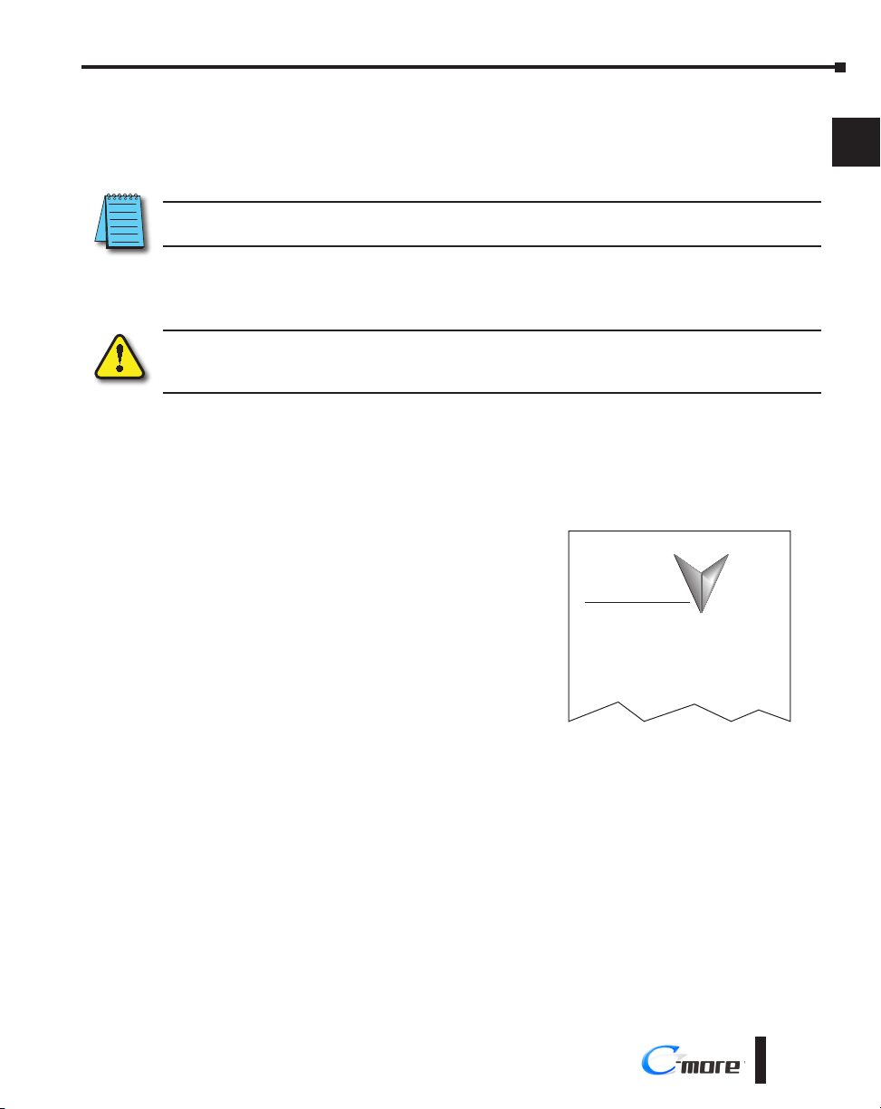
Step 1 – Unpack and Inspect
a.) Unpack the C-more RHMI from its shipping carton. A Quick Start Guide is included in
the carton.
b.) Unpack any accessories that have been ordered, such as programming cable,
communications cable, etc.
c.) Inspect all equipment for completeness. If anything is missing or damaged, immediately
call the AutomationDirect® returns department @ 1-800-633-0405.
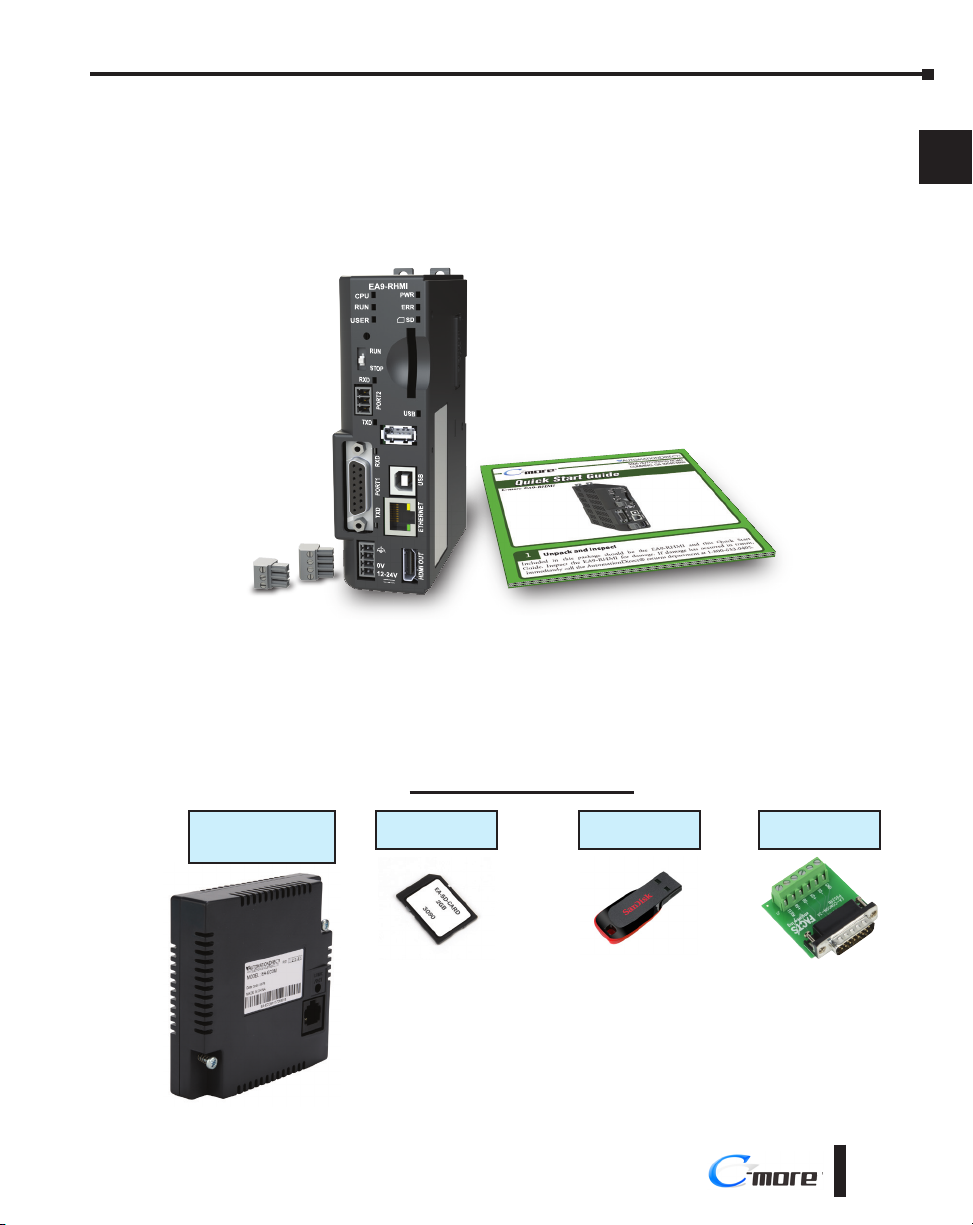
Optional Accessories
1
2
3
4
5
6
7
8
9
10
11
12
Communication
Expansion Module
EA-ECOM
EA9-RHMI-USER-M Hardware User Manual, 1st Ed. Rev. G
SD Memory Card
EA-SD-CARD
USB Pen Drive
USB-FLASH
DSUB Port Adapter
EA-COMCON-3A
®
13
14
A
B
C
D
1-5
Page 20
Chapter 1 - Getting Started
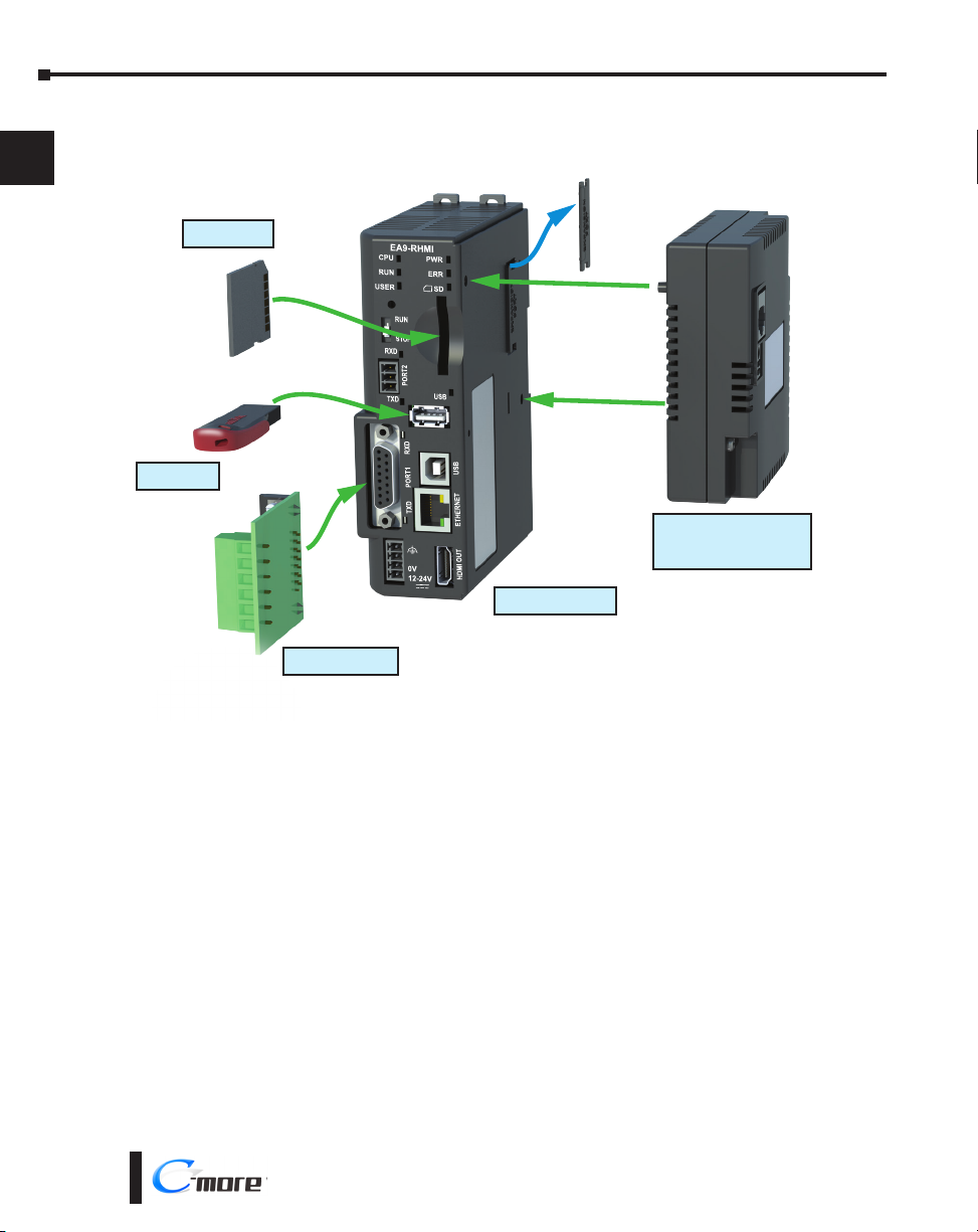
Step 2 – Install Optional Hardware Accessories
1
2
3
4
5
6
7
8
9
10
11
12
EA-SD-CARD
USB-FLASH
EA-ECOM
Ethernet Communication
Module
C-more EA9-RHMI
EA-COMCON-3A
13
14
A
B
C
D
1-6
®
EA9-RHMI-USER-M Hardware User Manual, 1st Ed. Rev. G
Page 21
Chapter 1 - Getting Started
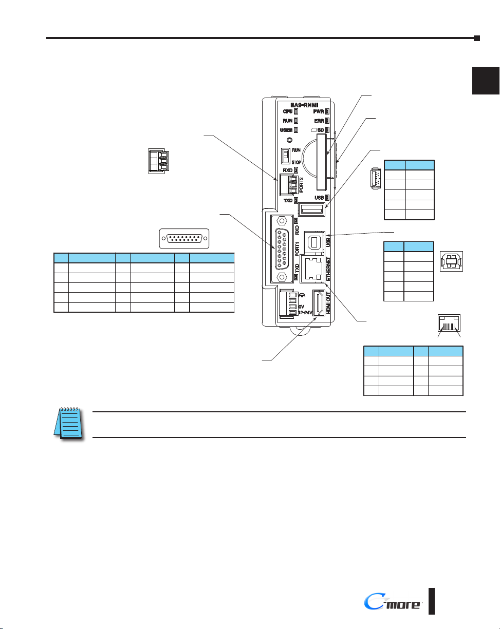
Step 3 – Become Familiar with Available Communication Ports
Pin Signal
1 Frame GND
TXD (232C)
2
RXD (232C)
3
N.C.
4
5 Logic GND
Port 2
Serial Communication
RS-485
Logic Ground
–
+
EA9-3TB
Port 1
PLC Serial Communications
RS-232C / RS-422 / RS-485
8 1
15 9
Pin Signal Pin Signal
6 LE (for DH485)
CTS (232C)
7
RTS (232C)
8
RXD+ (422/485)
9
10 RXD– (422/485)
11 TXD+ (422/485)
TXD– (422/485)
12
Term. Resistor
13
N.C.
14
15 N.C.
HDMI Port Video Out
SD Card Slot
Expansion Port
(Right Side)
USB Port - Type A
USB Device Options
Pin Signal
4
1 Vbus
3
21
Ethernet 10/100 Base-T
PLC Communications,
Programming/Download
Pin Signal
1 TD+
2
3
4
2
3
4
USB Port - Type B
Programming
Pin Signal
1 N.C.
2
3
4
TD–
RD+
do not use
D–
D+
GND
ShieldSHELL
D–
D+
GND
ShieldShell
Pin Signal
2
3
1 8
5 Do not use
RD–
6
N.C.
7
N.C.
8
1
2
3
4
5
6
7
1
4
8
9
10
11
12
NOTE: See Chapter 6: PLC Communications for additional details on the available communication ports, protocols
and cables.
EA9-RHMI-USER-M Hardware User Manual, 1st Ed. Rev. G
®
13
14
A
B
C
D
1-7
Page 22

Chapter 1 - Getting Started
Step 4 – Install the Programming Software and Develop a Project
1
2
3
4
5
6
7
8
9
10
11
Download the latest version of the C-more Programming Software, p/n EA9-PGMSW,
from the Automationdirect website. Alternately, if the C-more Programming Software CD is
available, you may install from the software CD. Refer to the AutomationDirect website for
current minimum system requirements for installation.
For software download installation, follow the screen prompts to download and install the
C-more Programming Software.
For CD installation, insert the supplied CD into the PC’s CD drive and navigate to the CD
drive location on the PC. Double-click on EA_Setup.exe and follow the instructions. If you
need assistance during the software installation, call the AutomationDirect Technical Support
team @ 770-844-4200.
NOTES: Regarding Ethernet access to a C-more panel.
If you intend to take advantage of the methods of remote access to the panel, including the web server, PC remote
access, FTP, iOS or Android app, you need to consider the security exposure in order to minimize the risks to your
process and your C-more panel.
Security measures may include password protection, changing the ports exposed on your network, including a VPN
in your network, and other methods. Security should always be carefully evaluated for each installation. Refer to
Appendix C - Security Considerations for Control Systems Networks.
12
13
14
A
B
C
D
1-8
®
EA9-RHMI-USER-M Hardware User Manual, 1st Ed. Rev. G
Page 23
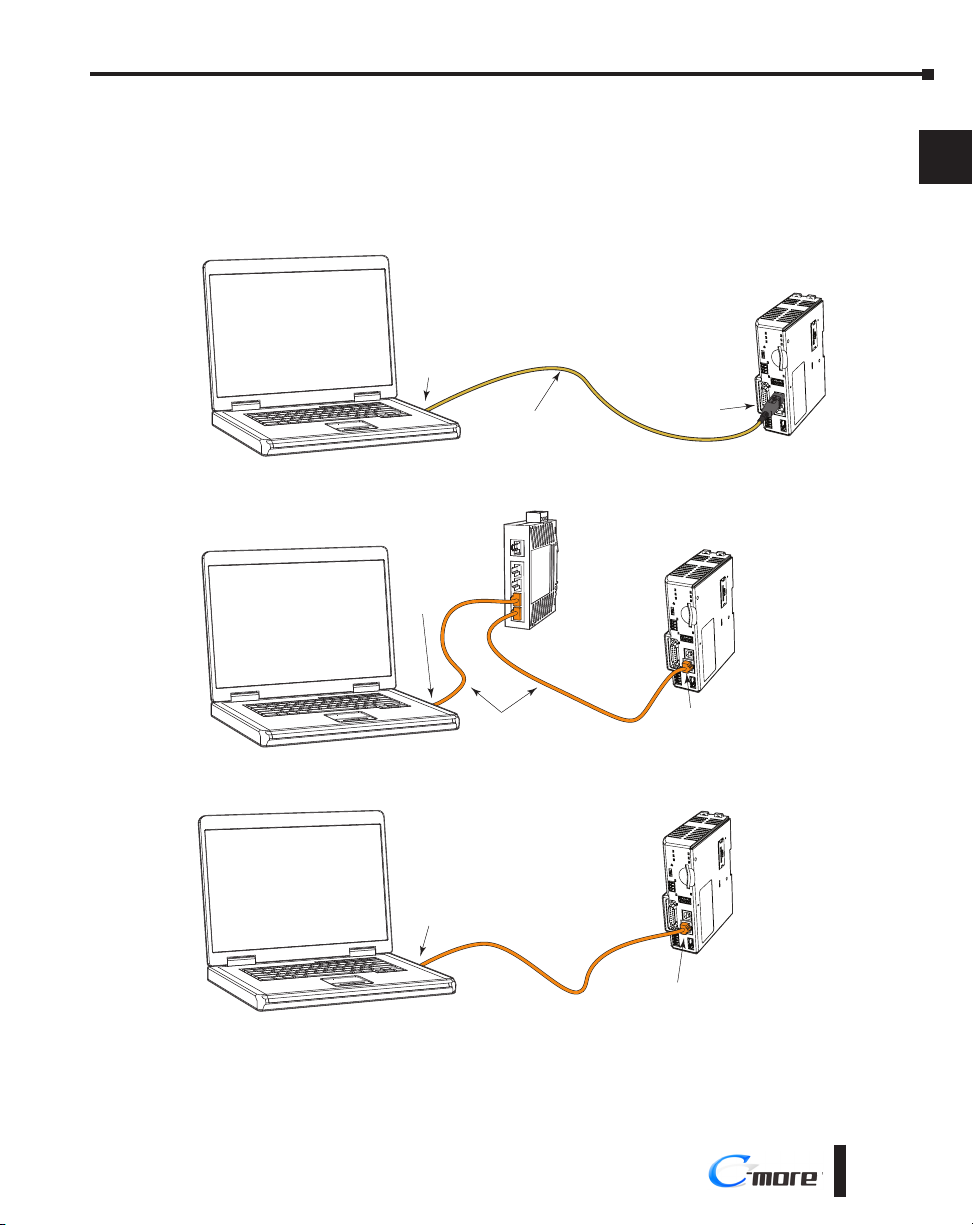
Step 5 – Connect HMI to Computer
• Connect a USB Programming Cable, such as p/n USB-CBL-AB15, from a USB type A port on the
PC to the USB type B programming port on the C-more HMI.
• Or connect the C-more EA9-RHMI and PC together either directly or via an Ethernet switch and
CAT5 Ethernet cables
PC
Chapter 1 - Getting Started
C-more
EA9-RHMI
1
2
3
PC
PC
USB
Port
Stride™
Ethernet Switch
10/100 Base-T
(such as SE2-SW5U)
Ethernet
Port
Ethernet
Port
USB-CBL-ABxx
USB Cable
Ethernet CAT5
Cable
Ethernet CAT5
Cable
USB
Port
C-more
EA9-RHMI
Auto MDI / MDI-X
Ethernet Port
C-more
EA9-RHMI
4
5
6
7
8
9
10
11
12
13
14
A
Auto MDI / MDI-X
Ethernet Port
EA9-RHMI-USER-M Hardware User Manual, 1st Ed. Rev. G
B
C
D
®
1-9
Page 24
Chapter 1 - Getting Started
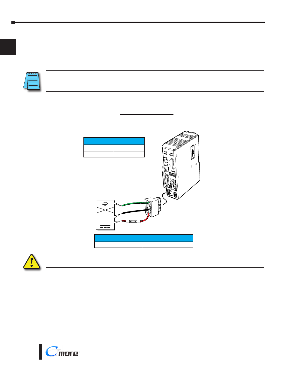
Step 6 – Provide Power to the HMI
• Connect a dedicated 12-24 VDC Class 2 power supply to the DC connector on the front of the
1
2
3
C-more EA9-RHMI. Make sure to connect the ground terminal to a proper equipment ground.
• Then turn on the power source and check the LED status indicators on the front of the C-more
EA9-RHMI for proper indication (see next page).
NOTE: A dedicated power supply is recommended. If the power supply also feeds inductive loads such as
solenoids or relays, the transients caused by these loads can affect the operation of or cause damage to HMI
components.
4
5
6
7
8
9
10
11
12
13
14
A
DC Power Wiring
Recommended Fuse
Rating ADC part number
2.5 A MDL2-5
Equipment
Ground
0V
12- 24 VDC
Tightening Torque
Power supply cable torque 32-35 oz-in (0.22-0.25 Nm)
Warning: Use 60/75 °C copper conductors only.
C0-4TB
Terminal Block
B
C
D
1-10
®
EA9-RHMI-USER-M Hardware User Manual, 1st Ed. Rev. G
Page 25
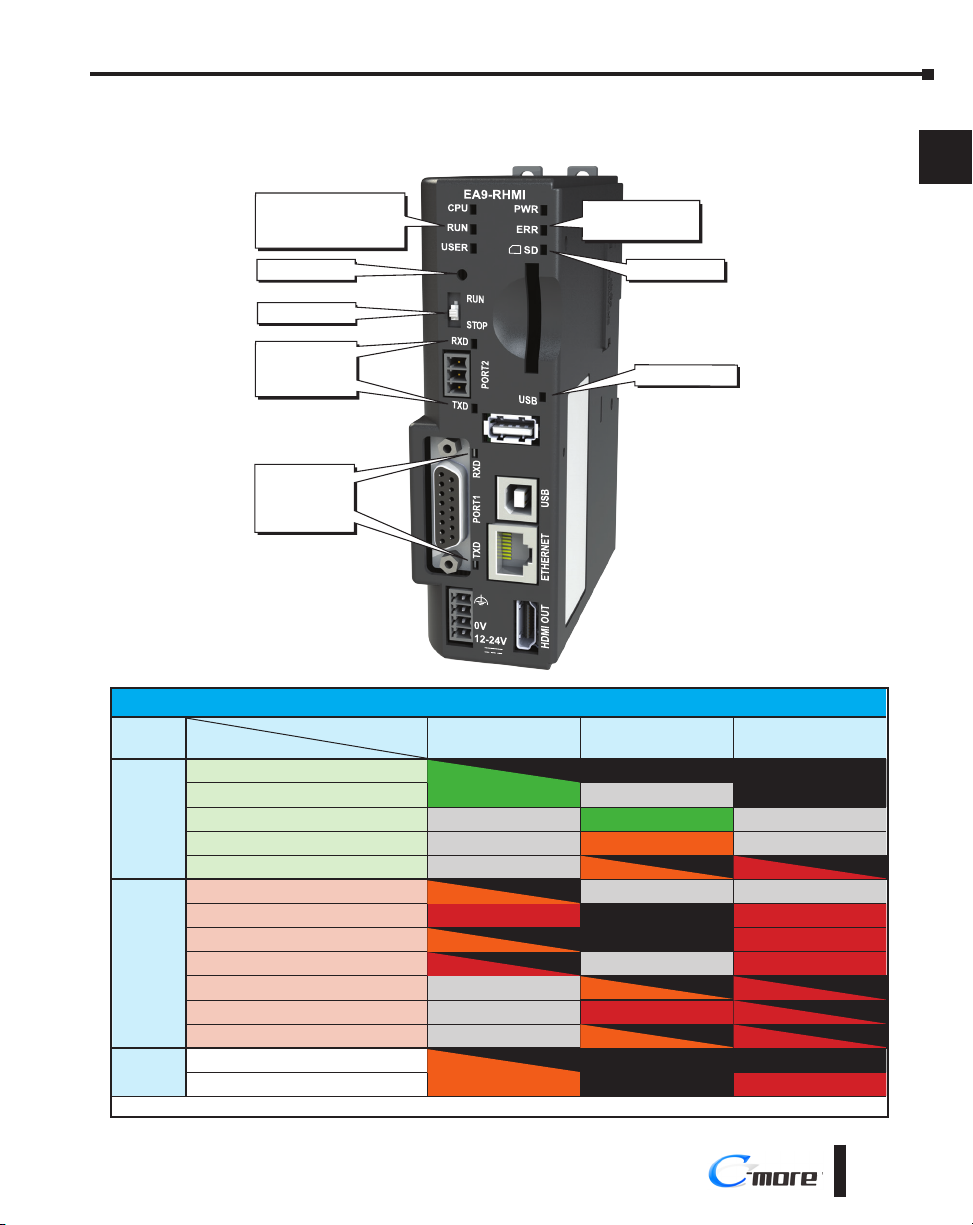
Step 6 – Provide Power to the HMI (cont’d)
C-more LED Status Indicators
System Status LEDs
- CPU Green/Red/Orange
- RUN Green/Red/Orange
- USER Green/Red/Orange
Reset Button
Chapter 1 - Getting Started
System Status LEDs
- PWR Green
- ERR Red
SD Status Green
1
2
3
RUN / STOP Switch
Receive Green
Port 2 Serial Port
Transmit Green
Receive Green
Port 1 Serial Port
Transmit Green
System Status LEDs
State
LED
Status Loading OS
CPU Running Normal
Project Loaded and Running
No User Project
Password Required
Errors Power Loss Detection
Memory Error
OS Error
Watch Dog Time Out
No Log Storage Found
General Error*
Warning*
Mode Recovery Mode
Safe Mode
*Note - See Chapter 8 - Troubleshooting for General Error and Warning explanations.
CPU RUN ERR
Blinking Green (0.5s) OFF OFF
Green – OFF
– Green –
– Orange –
– Blinking Orange (0.5s) Blinking Red (0.5s)
Blinking Orange (0.2s) – –
Red OFF Red
Blinking Orange (0.5s) OFF Red
Blinking Red (0.5s) – Red
– Blinking Orange (0.5s) Blinking Red (0.5s)
– Red (0.5s) Blinking Red (0.5s)
– Blinking Orange (0.5s) Blinking Red (0.5s)
Blinking Orange (0.5s) OFF OFF
Orange OFF Red
USB Status Green
4
5
6
7
8
9
10
11
12
13
14
A
B
C
D
EA9-RHMI-USER-M Hardware User Manual, 1st Ed. Rev. G
®
1-11
Page 26
Chapter 1 - Getting Started
EA9-RHMI Beep
1
2
3
4
5
6
Function Beep Pattern
Boot 1-long, 2-short
Boot Error* 3-long
HDMI Connected 3-short
Reset to Factory Defaults 14 short beeps progressively closer together followed by 1-long beep.
Blink Screen 5-long
*Boot Errors
Multiple Projects
Write Protected SD Card
No Log Storage Found
System Screen (RUN/STOP switch in STOP position)
Password Protected
Beep Functions
7
8
9
10
11
12
13
14
A
B
C
D
Reset Button
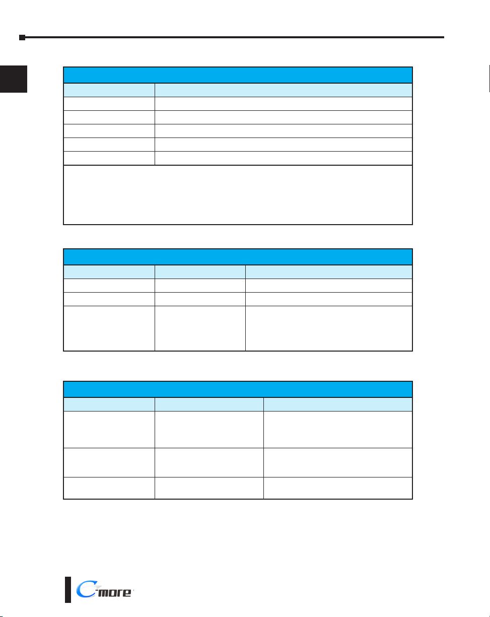
Reset Button
Push Action Behavior Note
Push for <15 seconds Reboot the EA9-RHMI
Push for >15 seconds Reset to factory default The project is cleared and all settings are initialized.
While holding down the
reset button, power on the
EA9-RHMI and continue
holding the button for
>15 seconds
RUN / STOP switch
Position Behavior Note
RUN
STOP
Power on the EA9-RHMI
while in the STOP position
System recovery mode
RUN / STOP Switch
Project will run if present and the
RUN LED will be green
The project and any logging
stops and the System Screen is
displayed.
The System Screen is displayed A System Screen password is ignored.
The CPU LED will blink ORANGE. See “No System
Found” in Chapter 8 - Troubleshooting
If no project is loaded in the HMI, the
message “No User Program” will be displayed
on a connected display. The RUN LED will be
orange.
If a password has been set up for the System
Screen, the RUN LED will blink orange.
User Defined LED
The user defined LED on the EA9-RHMI can be controlled from the project to illuminate
red, green or orange. It can also be configured to blink these colors. Refer to the online help
file provided with the programming software for details.
1-12
®
EA9-RHMI-USER-M Hardware User Manual, 1st Ed. Rev. G
Page 27
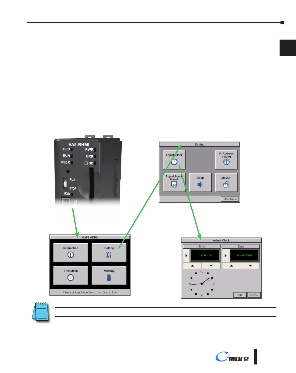
Step 7 – Access the EA9-RHMI Setup Screens
• Access the Main Menu of the EA9-RHMI System Setup Screens by changing the selector switch on
the front of the unit to STOP.
• Adjust the time and date for the panel by pressing the Setting button on the Main Menu. Then
press the Adjust Clock button on the Setting screen.
• Use the right-pointing arrows for the time or date display to select the unit to change. Use the up
and down arrows to increment or decrement the value for the selected unit.
• Press OK when done to accept the changes to the time and date in the HMI or press Cancel to exit
the Adjust Clock setup screen without making any changes.
• Press the Main Menu button on the Setting screen and then the Exit button on the Main Menu
screen to return to the application screen.
• Change the selector switch on the front of the unit to RUN.
Chapter 1 - Getting Started
1
2
3
4
5
6
7
8
9
NOTE: For more information on EA9-RHMI setup screens, see Chapter 5 - System Setup Screens.
EA9-RHMI-USER-M Hardware User Manual, 1st Ed. Rev. G
®
10
11
12
13
14
A
B
C
D
1-13
Page 28
Chapter 1 - Getting Started
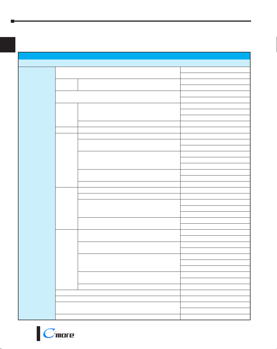
Step 8 – Choose HMI to Device Cable
The table below shows the PLCs, controllers and protocols supported by the EA9-RHMI.
1
2
Model Protocols
Ensure your controller and protocol are supported.
3
4
5
6
7
8
9
10
AutomationDirect
11
12
13
14
A
B
C
D
PLC Protocol Table
Productivity Series
Do-more
(BRX)
CLICK
DL05/DL06
DL105 all K-Sequence
DL205
DL305
DL405
H2-WinPLC (Think & Do) Live V5.2 or later and Studio any version Think & Do Modbus RTU (serial port)
H2-WinPLC (Think & Do) Live V5.5.1 or later and Studio V7.2.1 or later Think & Do Modbus TCP/IP (Ethernet port)
GS Drives
SOLO Temperature Controllers (models with serial communications) SOLO Temperature Controller
all
all
H0-ECOM/H0-ECOM100
D2-230 K-Sequence
D2-240
D2-250/D2-250-1/D2-260/D2-262
D2-240/D2-250-1/D2-260
Using DCM
H2-ECOM/H2-ECOM100
D3-330/330P (Requires the use of a Data Communications Unit)
D3-340
D3-350
D3-350 DCM
D4-430
D4-440
D4-450/D4-454
All with DCM
H4-ECOM/H4-ECOM100
Productivity Serial
Productivity Ethernet
Do-more Serial
Do-more Ethernet
Modbus (CLICK addressing)
Modbus TCP (CLICK addressing)
K-Sequence
Direct NET
Modbus (Koyo addressing)
Direct LOGIC Ethernet
K-Sequence
Direct NET
K-Sequence
Direct NET
Modbus (Koyo addressing)
Direct NET
Modbus (Koyo addressing)
Direct LOGIC Ethernet
Direct NET
Direct NET
K-Sequence
Direct NET
Modbus (Koyo addressing)
Direct NET
Modbus (Koyo addressing)
K-Sequence
Direct NET
K-Sequence
Direct NET
K-Sequence
Direct NET
Modbus (Koyo addressing)
Direct NET
Modbus (Koyo addressing)
Direct LOGIC Ethernet
GS Drives Serial
GS Drives TCP/IP (GS-EDRV)
1-14
®
EA9-RHMI-USER-M Hardware User Manual, 1st Ed. Rev. G
Page 29
Chapter 1 - Getting Started
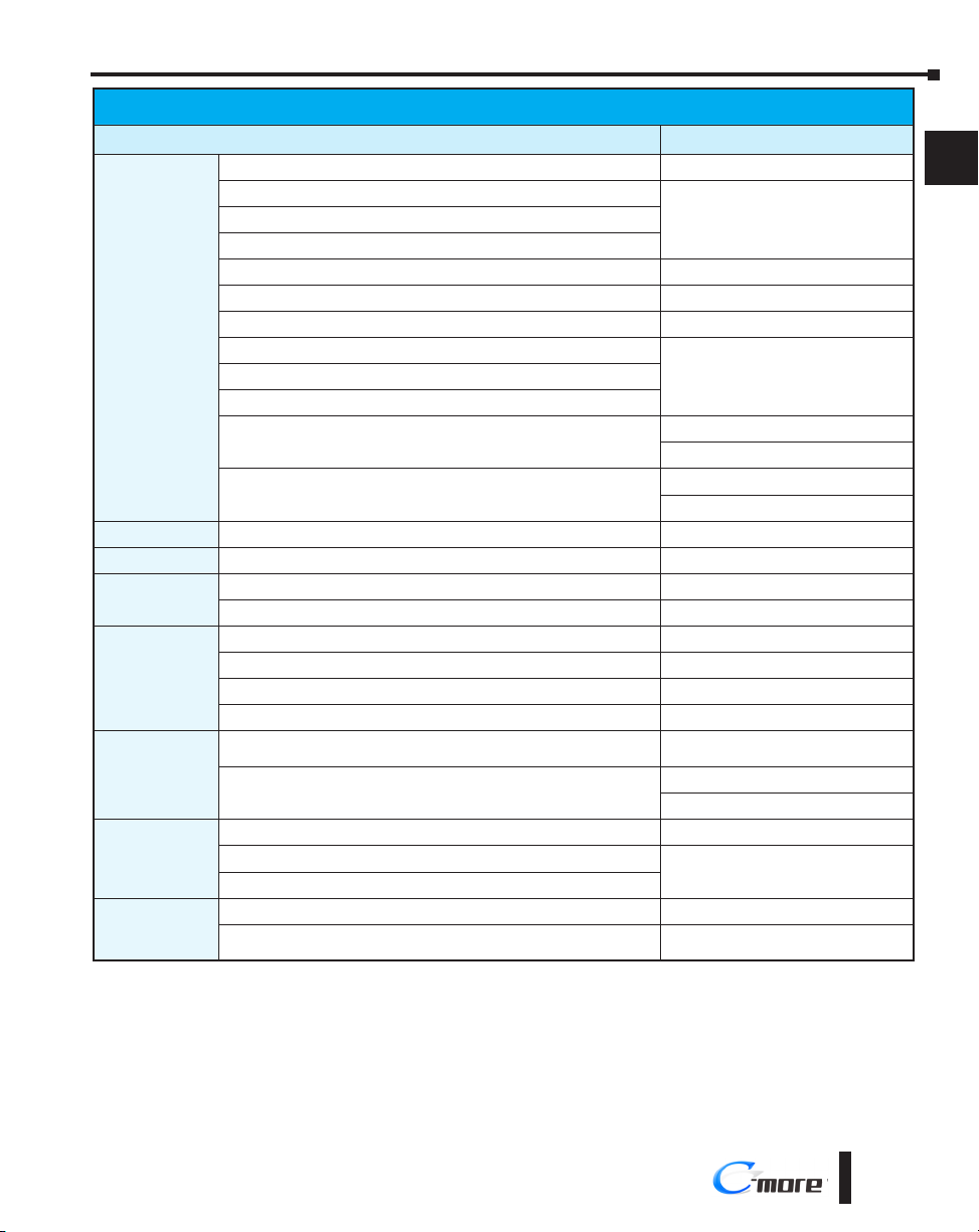
Step 8 – Choose HMI to Device Cable (cont’d)
Model Protocols
MicroLogix 1000, 1100, 1200, 1400, 1500, SLC 5-01/02/03 DH485/AIC/AIC+
MicroLogix 1000, 1100, 1200, 1400 and 1500
ControlLogix™, CompactLogix™, FlexLogix™
PLC-5 DF1 Full Duplex
ControlLogix, CompactLogix, FlexLogix - Tag Based DF1 Half Duplex; DF1 Full Duplex
Allen-Bradley
Modbus RTU
Modbus TCP/IP
GE
Mitsubishi
Modicon
Omron
Siemens
ControlLogix, CompactLogix, FlexLogix - Generic I/O Messaging EtherNet/IP Server
ControlLogix, CompactLogix, FlexLogix - Tag Based
MicroLogix 1100, 1400 and SLC 5/05, via native Ethernet port
MicroLogix 1000, 1100, 1200, 1400, 1500, SLC 5-03/04/05, all via ENI adapter
Micro 800 Series
Micro 800 Series - Tag Based
Modbus RTU devices Modbus RTU
Modbus TCP/IP devices Modbus TCP/IP
90/30, 90/70, Micro 90, VersaMax Micro SNPX
90/30, Rx3i SRTP Ethernet
FX Series FX Direct
Q02, Q02H, Q06H, Q12H, Q25H Q CPU
Q, QnA Serial QnA Serial
Q, QnA Ethernet QnA Ethernet
984 CPU, Quantum 113 CPU, AEG Modicon Micro Series 110 CPU: 311-xx, 411-xx,
512-xx, 612-xx
Other devices using Modicon Modbus addressing
C200 Adapter, C500 Host Link
CJ1/CS1 Serial
CJ1/CS1 Ethernet
S7-200 CPU, RS-485 Serial PPI
S7-200 CPU, S7-300 CPU, S7-400, S7-1200 CPU
Ethernet
PLC Protocol Table (cont’d)
DF1 Half Duplex; DF1 Full DuplexSLC 5-03/04/05
EtherNet/IP Client
Modbus RTU
Modbus TCP
DF1 Full Duplex
EtherNet/IP Client
Modbus RTU
Modbus RTU
TUModbus TCP/IP
FINS
Ethernet ISO over TCP
1
2
3
4
5
6
7
8
9
10
11
12
13
14
A
B
EA9-RHMI-USER-M Hardware User Manual, 1st Ed. Rev. G
®
C
D
1-15
Page 30
Chapter 1 - Getting Started
Step 8 – Choose HMI to Device Cable (cont’d)
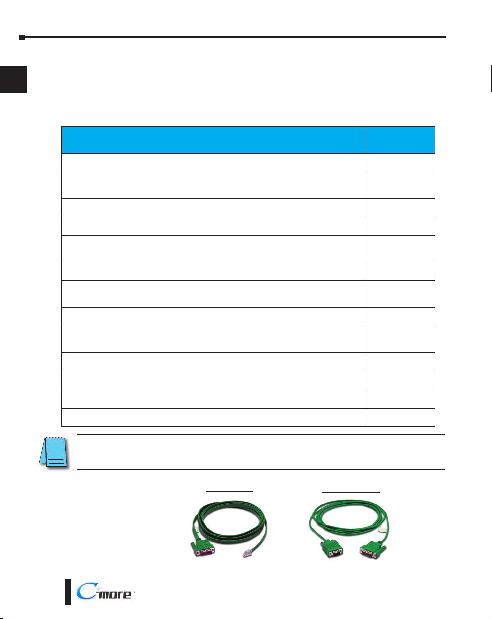
Available cables to connect from PLC to C-more serial Port 1
1
2
To use Serial communication through Port 1 of the EA9-RHMI, consult the chart below for
the proper cable. See Chapter 6: PLC Communications for wiring diagrams of additional user
contructed cables.
3
4
5
6
7
8
9
10
11
12
13
Cable
Description
Communication cable, 15-pin D-shell male to 6-pin RJ12, 9.8ft/3m cable length. For use with
C-more or C-more Micro panel and AutomationDirect PLCs with RJ12 ports.
Communication cable, 15-pin D-shell male to 15-pin D-sub HD15 male, 3m/9.8ft cable length.
For use with C-more or C-more Micro panel and a DL06, D2-250(-1), D2-260 or D2-262 (bottom
port) CPU.
Communication cable, 15-pin D-shell male to 6-pin RJ11, 3m/9.8ft cable length. For use with
C-more or C-more Micro panel and a D3-340 CPU top or bottom port.
Communication cable, 15-pin D-shell male to 15-pin D-shell male, 3m/9.8ft cable length. For use
with C-more or C-more Micro panel and a DL405 (top port) CPU.
Communication cable, 15-pin D-shell male to 25-pin D-shell male, 3m/9.8ft cable length. For
use with C-more or C-more Micro panel and a D2-DCM, D3-232-DCU, D3-350 (bottom port) or
DL405 (bottom port) CPU.
Communication cable, 15-pin D-shell male to 8-pin mini DIN male, 3m/9.8ft cable length. For use
with C-more or C-more Micro panel and an Allen-Bradley Micrologix CPU.
Communication cable, 15-pin D-shell male to 9-pin D-shell female, 3m/9.8ft cable length. For use
with C-more or C-more Micro panel and an Allen-Bradley SLC 5/03, 5/04 or 5/05 CPU with DF-1
port.
Communication cable, 15-pin D-shell male to 25-pin D-shell male, 3m/9.8ft cable length. For use
with C-more or C-more Micro panel and an Allen-Bradley PLC-5 CPU with a DF1 port.
Communication cable, 15-pin D-shell male to 6-pin RJ45, 3m/9.8ft cable length. For use with
C-more or C-more Micro panel and an Allen-Bradley SLC 5/01, 5/02 or 5/03 CPU with a DH485
port cable.
Communication cable, 15-pin D-shell male to 15-pin D-shell male, 3m/9.8ft cable length. For use
with C-more or C-more Micro and GE Fanuc Series 90/30 or 90/70 serial port.
Communication cable, 15-pin D-shell male to 25-pin D-shell male, 3m/9.8ft cable length. For use
with C-more or C-more Micro panel and a Mitsubishi FX Series CPU.
Communication cable, 15-pin D-shell male to 8-pin mini DIN male, 3m/9.8ft cable length. For use
with C-more or C-more Micro panel and a Mitsubishi FX Series CPU.
Communication cable, 15-pin D-shell male to 25-pin D-shell male, 3m/9.8ft cable length. For use
with C-more or C-more Micro panel and an Omron C200 or C500 CPU.
Cable
Part Number
EA-2CBL
EA-2CBL-1
EA-3CBL
EA-4CBL-1
EA-4CBL-2
EA-MLOGIX-CBL
EA-SLC-232-CBL
EA-PLC5-232-CBL
EA-DH485-CBL
EA-90-30-CBL
EA-MITSU-CBL
EA-MITSU-CBL-1
EA-OMRON-CBL
14
A
B
C
D
1-16
NOTE: The above list of pre-made communications cables may be purchased. See Chapter 6: PLC
Communications for wiring diagrams of additional user constructed cables. Chapter 6 also includes wiring diagrams
for the pre-made cables.
Pre-made cable
examples
®
EA-2CBL
EA9-RHMI-USER-M Hardware User Manual, 1st Ed. Rev. G
EA-2CBL-1
Page 31

Chapter 1 - Getting Started
Step 9 – Connect HMI to PLC
• Connect the serial communications cable between the C-more EA9-RHMI and the PLC
• Or connect the C-more EA9-RHMI and PLC together either directly or via an Ethernet switch and
CAT5 Ethernet cables.
For further information on setting up communications between the EA9-RHMI and a PLC, see the
C-more programming help file topic CM129: Creating a New Project.
Serial
C-more
DL-06 PLC
EA9-RHMI
1
2
3
4
Port 2
Ethernet via Switch
CLICK PLC
Ethernet CAT5
Cable
Ethernet
CLICK PLC
Serial Port
EA-2CBL-1
Stride™
Ethernet Switch
10/100 Base-T
(such as SE2-SW5U)
C-more
EA9-RHMI
EA9-RHMI
Auto MDI / MDI-X
Ethernet Port
C-more
5
6
7
8
9
10
11
12
13
14
A
Ethernet CAT5
Cable
EA9-RHMI-USER-M Hardware User Manual, 1st Ed. Rev. G
Auto MDI / MDI-X
Ethernet Port
®
B
C
D
1-17
Page 32

Page 33

Chapter
Chapter
Chapter
SpecificationS
2
2
2
In This Chapter...
Specifications .................................................................................................................2-2
Dimensions ....................................................................................................................2-4
Inches [mm] �����������������������������������������������������������������������������������������������������������������2-4
Communication Ports and Memory Expansion ............................................................2-5
Compatible Touch Screen Monitors .............................................................................2-7
Handling External Memory Devices ..............................................................................2-8
Writing to External Memory Devices ����������������������������������������������������������������������������2-8
Memory Device Formatting ������������������������������������������������������������������������������������������2-8
Minimizing Data Errors �������������������������������������������������������������������������������������������������2-9
Monitoring Available Memory �������������������������������������������������������������������������������������2-9
File Name Limitations �������������������������������������������������������������������������������������������������2-10
Power Loss Retention �������������������������������������������������������������������������������������������������2-10
Page 34

Chapter 2 - Specifications
Specifications
1
2
3
4
5
6
7
8
9
10
11
12
13
14
A
The C-more® RHMI Operator Interface is the next generation of HMI brought to you
by AutomationDirect. It has been designed to display and interchange graphical data from
a PLC by connecting a monitor and USB mouse or compatible touch screen or accessing
screens remotely from a PC or smart device app.
Operating Temperature
Altitude
Storage Temperature
Humidity
Environment
Noise Immunity
Withstand Voltage
Insulation Resistance
Vibration
Shock
Specifications continued on next page
EA9-RHMI Specifications
0 to 50°C (32 to 122°F); Maximum surrounding air temperature rating: 50°C (122°F)
For use in Pollution Degree 2 environment, no corrosive gases permitted
(EN61131-2)
EN61000-4-2 (ESD): 4kV (Contact Discharge)
EN61000-4-3 (RFI): 10V/m (80MHz-1GHz), 3V/m (1.4GHz-2.0GHz)
EN61000-4-4 (FTB): 2kV, positve/negative, 5kHz (DC power port)
EN61000-4-5 (Surge): 0.5kV line to line
EN61000-4-6 (Conducted): 10V, 0.15–80MHz
EN61000-4-8 (Power frequency magnetic field immunity): 30A/m
(Local test)
RFI, (145MHz, 440MHz 10W @10cm)
Impulse 1000V @ 1µs pulse
10 sweep cycles per axis on each of 3 mutually perpendicular axes
IEC 60068-2-14 (Test Nb, Thermal Shock)
Up to 2000m (6562ft)
–20 to +60°C (–4 to +140°F)
IEC 60068-2-1 (Test Ab, Cold)
IEC 60068-2-2 (Test Bb, Dry Heat)
IEC 60068-2-14 (Test Na, Thermal Shock)
5–95% RH (non-condensing)
2kV/4kV/8kV (Air Discharge)
1V/m (2.0GHz-2.7GHz)
0.5kV line to earth
1000VAC, 1 min. (FG to power supply )
> 10M ohm @ 500VDC (FG to power supply )
IEC60068-2-6 (Test Fc)
5-9Hz: 3.5mm amplitude, 9-150Hz 1.0G
IEC60068-2-27 (Test Ea)
15G peak, 11ms duration, 3 shocks in each direction per axis,
on 3 mutually perpendicular axes
B
C
D
2-2
NOTE: The touch screen driver is designed to respond to a single touch. If it is touched at multiple points at the
same time, an unexpected object may be activated.
®
EA9-RHMI-USER-M Hardware User Manual, 1st Ed. Rev. G
Page 35

Emission
Supply Power
Weight
Color Scale
Project Memory
Number of Screens
Realtime Clock
Calendar Month / Day / Year
Serial Port 1
Serial Port 2
USB Port - Type B
USB Port - Type A
Supported Touch Screen
Ethernet Port
SD Card Slot
HDMI Video Out
Power Consumption
Maximum Inrush Currnet
Recommended Fuse
Internal Fuse
(non-replaceable)
Agency Approvals
Chapter 2 - Specifications
EA9-RHMI Specifications (continued)
EN55011 Class A (Radiated RF emission)
10.2-26.4 VDC Class2 or SELV (Safety Extra-Low Voltage) Circuit or Limited Energy Circuit
Realtime Clock built into unit, backed up for 30 days at 25°C after power has been applied for
USB 2.0 High speed (480 Mbps) Type B - Download/Program
USB 2.0 High speed (480 Mbps) Type A - for USB device options
ELO™ Single Touch Resistive/SAW, EETI eGalax Single Touch Resistive and pCAP
Ethernet Port Ethernet 10/100 Base-T, auto MDI/MDI-X
UL61010 (E157382), CE (EN61131-2), cUL Canadian C22.2, RoHS (2011/65/EU)
(LEC), Reverse Polarity Protected
0.59 lb (269g)
65,536 colors
82MB
Up to 999 screens – limited by project memory
24 hours
Yes - monthly deviation 60 sec at 25°C
15-pin D-sub female - RS2342C, RS-422/485
3-wire terminal block - RS-485
Max cable length - 15 ft.
Max cable length - 15ft
Bus Power – Less than 500mA at 5VDC
1 slot. Supports max 2GB (SD,) max 32GB (SDHC)
HDMI Type A Port
12.0 W
1.0 A @ 12VDC
0.5 A @ 24VDC
15A @ 1ms
2.5 A (part no. MDL2-5)
4A
1
2
3
4
5
6
7
8
9
10
11
12
13
14
EA9-RHMI-USER-M Hardware User Manual, 1st Ed. Rev. G
A
B
C
D
®
2-3
Page 36

Chapter 2 - Specifications
Dimensions
1
2
3
4
5
6
7
8
9
10
11
Inches [mm]
12
13
14
A
B
C
D
2-4
®
EA9-RHMI-USER-M Hardware User Manual, 1st Ed. Rev. G
Page 37

Chapter 2 - Specifications
Communication Ports and Memory Expansion
Pin Signal
1 Frame GND
TXD (232C)
2
RXD (232C)
3
N.C.
4
5 Logic GND
Port 2
Serial Communication
RS-485
Logic Ground
–
+
EA9-3TB
Port 1
PLC Serial Communications
RS-232C / RS-422 / RS-485
8 1
15 9
Pin Signal Pin Signal
6 LE (for DH485)
CTS (232C)
7
RTS (232C)
8
RXD+ (422/485)
9
10 RXD– (422/485)
11 TXD+ (422/485)
TXD– (422/485)
12
Term. Resistor
13
N.C.
14
15 N.C.
HDMI Port Video Out
SD Card Slot
Expansion Port
(Right Side)
USB Port - Type A
USB Device Options
Pin Signal
4
1 Vbus
3
21
Ethernet 10/100 Base-T
PLC Communications,
Programming/Download
Pin Signal
1 TD+
2
3
4
2
3
4
USB Port - Type B
Programming
Pin Signal
1 N.C.
2
3
4
TD–
RD+
do not use
D–
D+
GND
ShieldSHELL
D–
D+
GND
ShieldShell
1 8
Pin Signal
5 Do not use
RD–
6
N.C.
7
N.C.
8
1
2
3
4
5
6
1
2
3
7
4
8
9
10
11
12
HDMI Port Video Out
Resolution
Output
Sound Pass Through
EA9-RHMI-USER-M Hardware User Manual, 1st Ed. Rev. G
EA9-RHMI Video Out Specifications
SD - 720 x 480
HD - 1280 x 720
VGA - 640 x 480
XGA - 1024 x 768
Video Data - Same Screen as Panel
Does not support Mic sound Pass Through
13
14
A
B
C
D
®
2-5
Page 38

Chapter 2 - Specifications
Ethernet Port
The Ethernet port can be used several ways: for programming the unit (downloading a
1
2
3
4
5
project), for PLC communication, and for the advanced features, such as sending e-mail, web
server, FTP access, and allowing users to access and control the HMI remotely.
The Ethernet connector is an RJ-45 Module jack.
Refer to http://c-more.automationdirect.com for the latest driver information.
USB Type B Port
Program C-more via the USB programming port. It’s fast and easy, with no baud rate settings,
parity, or stop bits to worry about. We stock standard USB cables for your convenience,
such as part no. USB-CBL-AB15. The USB type B port can be used to upload or download
projects to and from a PC (personal computer).
6
7
8
9
10
11
12
13
14
A
B
C
D
USB Type A Port
The USB type A port is a standard feature for all models and can be used to connect various
USB 2.0 HID (Human Input Device) devices to the HMI, such as:
• Industrial Monitor with a compatible touch screen or Mouse
• USB pen drives, (ADC p/n USB-FLASH)
• USB keyboards
• USB barcode scanners
• USB card scanners
C-more can log data to the USB pen drive as well as restore projects to the HMI from the pen
drive. You can also back up project files and HMI firmware.
NOTE: Output current is less than 500mA @ 5VDC.
Sound Interface (HDMI)
When connected to an HDMI device that supports audio over HDMI, C-more can play
warning sounds or pre-recorded messages such as “conveyor is jammed.” Various “Objects” in
the C-more programming software support sounds. C-more supports WAV type files. Sound
files are stored in the sound library.
Serial Communication Ports
Port 1
Connect to your serial controller network via Port 1. Port 1 is a 15-pin port that supports
RS-232 and RS-422/485.
Port 2
Connect your RS-485 network via Port 2. Port 2 is provided with a 3-wire removable
terminal block.
2-6
®
EA9-RHMI-USER-M Hardware User Manual, 1st Ed. Rev. G
Page 39

Compatible Touch Screen Monitors
The C-more EA9-RHMI supports both ELO Resistive and SAW touch screens and EETI
eGalax Resistive touch screens starting with firmware version 6.53. EETI eGalax single-touch
pCap touch screens are supported with firmware version 6.70.
NOTE: Check with the monitor manufacturer to make sure the monitor you purchase uses one of the drivers listed
below.
Chapter 2 - Specifications
1
2
3
Capactive, single or multi-touch touch screens are not supported
The manufacturers and models that have been tested at the time of firmware version 6.70
release are:
EA9-RHMI Compatible Touch Screen Monitors
Manufacturer / Distributor Models Driver
AutomationDirect
Hope Industrial Systems
ELO
Advantech
Tru-Vu
Dynics
Tru-Vu
Advantech
Atlas ELO 6.53 https://automationdirect.com
All Resistive Touch Screen Models ELO 6.53 https://www.hopeindustrial.com
All Resistive and SAW Touch Screen Models ELO 6.53 https://www.elotouch.com
IDS-3215R-40XGA1E Touch Screen Monitor
VMTR-15C-24 Touch Screen Monitor
FX15PTUMAD Touch Screen
ZBMT-18.5-R
FPM-221W-P4AE
eGalax -
Resistive
eGalax -
Resistive
eGalax -
Resistive
eGalax -
pCap
eGalax -
pCap
Minimum
Firmware
Version
6.53 https://www.advantech.com
6.53 https://tru-vumonitors.com
6.53 https://www.dynics.com
6.70 https://tru-vumonitors.com
6.70 https://www.advantech.com
Support Website
4
5
6
7
8
9
10
11
12
13
14
EA9-RHMI-USER-M Hardware User Manual, 1st Ed. Rev. G
A
B
C
D
®
2-7
Page 40

Chapter 2 - Specifications
Handling External Memory Devices
1
2
3
4
5
6
7
8
9
10
11
12
13
14
A
Writing to External Memory Devices
Different types of numeric and text data from the C-more HMI can be stored on an SD card
or a USB memory device. Numeric data from Line Trend Graph and PID Faceplate Trend
Graph objects may be stored. Text data from Lookup Text and Multi-state Text objects can
also be stored.
Up to 16 objects may be configured in the C-more programming software to log data. Along
with the 16 object limit, available storage on the external memory device is subject to the
memory capacity of the SD card or USB memory device. One log file is created in a 24 hour
period for each object. Additionally, logging data is initially stored in the buffer in the panel
MRAM and data is written to the external memory device when one of the following occurs:
• When 2kB of data is cached
• When 20 records have been stored
• Periodically, once every 1 minute
• When one of the “SYS Copy LogTo %device%” or “SYS %device% Eject” tags is turned on
• When there is an email or FTP action
• When the System Screen is called
• When the panel date is changed
Memory Device Formatting
Memory Devices should be formatted according to the following guidelines to ensure best
performance and integrity of logged data.
Item Capacity Supported Resolution Supported
up to 2GB FAT Yes
USB Memory Device
Type
SD Card
SD cards must be formatted using the SD formatter provided by the SD Association at
www.sdcard.org using the standard allocation unit size for best performance.
SD
SDHC
SDXC
4GB to 32GB FAT 32 Yes
64GB or larger exFAT Yes
up to 2GB FAT Yes
4GB to 32GB FAT 32 Yes
exFAT No
B
C
D
2-8
®
EA9-RHMI-USER-M Hardware User Manual, 1st Ed. Rev. G
Page 41

Chapter 2 - Specifications
Minimizing Data Errors
To minimize data errors when logging data to external memory, consider the following:
• Do not turn off power to the C-more HMI while the external memory device is being accessed.
• Do not remove any external memory device when the device is being accessed by the C-more panel.
The following internal tags should be used to monitor, access and safely remove external
memory devices:
SYS SD1 WriteStatus
SYS USB WriteStatus
SYS Copy LogToSD1
SYS Copy LogToUSB
SYS SD1 Eject
SYS USB Eject
SYS SD1 ReadyToUse
SYS USB ReadyToUse
• Be sure to back up the memory device at regular intervals.
• If you suspect the memory device is bad, you may want to use a PC to re-format the device, or use a
known good memory device.
• The number of times the memory device can be written to is limited. Consequently, logging
frequently will shorten the service life of the memory device. Using slower sample rates will increase
the life of the device.
Monitoring Available Memory
Each external memory device can be monitored and events can be configured to alert the user
when available memory is approaching the maximum capacity of the external memory device.
The following internal tags allow external memory devices data to be monitored:
SYS SD1 TotalMemory
SYS SD1 FreeMemory
SYS SD1 UsedMemory
SYS USB TotalMemory
SYS USB FreeMemory
SYS USB UsedMemory
Refer to the C-more programming software online help files for additional information on
system tags and managing data logging devices.
1
2
3
4
5
6
7
8
9
10
11
12
13
14
EA9-RHMI-USER-M Hardware User Manual, 1st Ed. Rev. G
A
B
C
D
®
2-9
Page 42

Chapter 2 - Specifications
File Name Limitations
There is a limit of 999 file names with the same first four characters. Internal file names
1
2
3
4
5
6
7
are restricted by the DOS 8-character-dot-3-character limit. Therefore trend log files are
identified internally by the first four characters of the object name plus tilde plus a three digit
number.
Examples are:
TREND GRAPH EAST CHILLER TEMP_130925.txt is saved internally as TREN~001.txt
TREND GRAPH WEST CHILLER TEMP_130925.txt is saved internally as TREN~002.txt
As new log files are created in each 24 hour period, these files count against the maximum of
999 files. If multiple graph objects appear on one screen, the files will be identified internally
by the first two characters of the screen name plus the first two characters of the object name
plus tilde plus three digit number.
To maximize storage capabilities on external memory devices, use screen names that have
unique characters in the first four digits and object names that are unique in the first two
characters.
NOTE: When the 999 filename limit is reached, the oldest files will automatically be deleted and logging will
continue.
8
9
10
11
12
13
14
A
B
C
D
Power Loss Retention
When a power loss is detected, the panel will attempt to complete all data logging operations
safely.
The power retention while using a DC power supply is not long enough to complete writes to
an SD Card or USB device. An Uninterruptable Power Supply (UPS) should be considered.
Power Loss Detection (at 25°C)
Power Supply Detect Loss
DC (Panel only) 8.9 VDC
2-10
®
EA9-RHMI-USER-M Hardware User Manual, 1st Ed. Rev. G
Page 43

Chapter
Chapter
Chapter
Accessories
3
3
3
In This Chapter...
Accessories Overview ................................................................................................. 3-2
EA-ECOM Ethernet Communication Module ............................................................ 3-3
D-SUB 15-pin to Terminal Block Adapter ................................................................. 3-4
SD Card ...................................................................................................................... 3-5
USB FLASH Drive ....................................................................................................... 3-5
Page 44

Chapter 3 - Accessories
Accessories Overview
1
2
3
4
5
6
7
8
9
10
11
12
EA-SD-CARD
USB-FLASH
C-more EA9-RHMI
EA-COMCON-3A
Part Number Description
EA-ECOM
EA-SD-CARD
USB-FLASH
Ethernet communication expansion module, (1) RJ45 10/100 Mbps Ethernet port.
SD memory card for non-volatile storage, 2GB industrial grade. 85°C maximum operating temperature
makes it suitable for data logging in industrial applications.
USB Flash drive, SanDisk, 32GB
EA-ECOM
13
14
A
B
C
D
EA-COMCON-3A
3-2
DSUB port adapter, 15-pin male to 6-pole RS-422/485 terminal block, straight cable entry
®
EA9-RHMI-USER-M Hardware User Manual, 1st Ed. Rev. G
Page 45
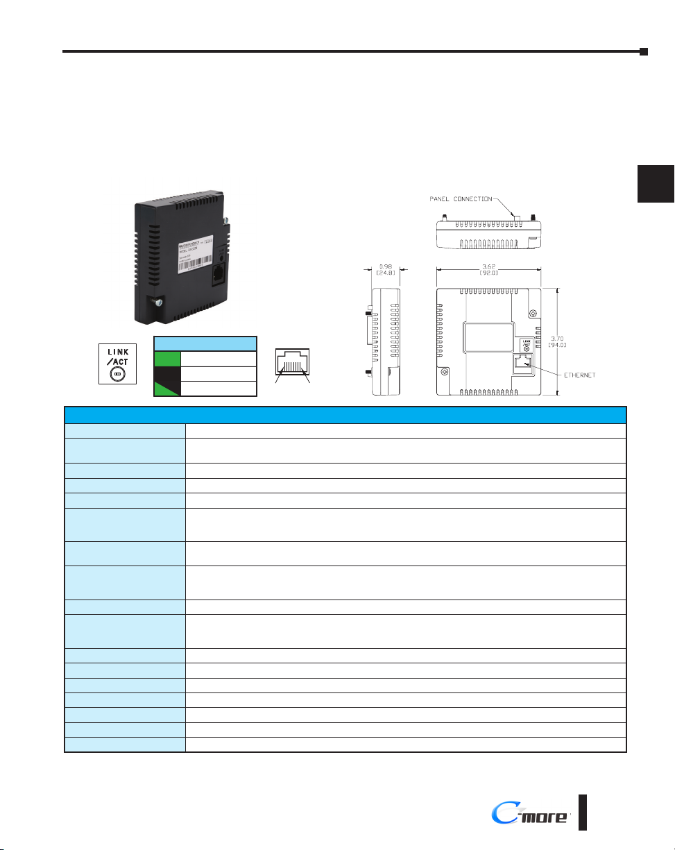
EA-ECOM Ethernet Communication Module
The EA-ECOM Ethernet Communication module plugs into the expansion port on the
C-more EA9-RHMI to allow a second Ethernet communication port for programming and
PLC communications at a speed of 10/100 Mbps.
EA-ECOM
Dimensions: Inches [mm]
Chapter 3 - Accessories
1
2
3
4
5
6
Blinking
Part Number
Operating Temperature
Storage Temperature
Humidity
Environmental Air
Vibration
Shock
Noise Immunity
Emission
Agency Approvals
Mounting Torque
Weight
Ethernet Specification
Communication Speed
Cable Specification
Auto MDI / MDI-X
Connector Type
Link Status LED (Green)
On Ethernet Linked
No Ethernet Comm.Off
Comm. Activity
Green
IEC60068-2-6 (Test Fc), 5-9 Hz: 3.5 mm amplitude, 9-150 Hz: 1.0 G, sweeping, at a rate of 1 octave/min.
1 8
EA-ECOM Specifications
EA-ECOM
Maximum surrounding air temperature rating: 50°C
10 sweep cycles per axis on each of 3 mutually perpendicular axes
IEC60068-2-27 (Test Ea), 15G peak, 11ms duration, three shocks in each direction
per axis, on 3 mutually perpendicular axes (total of 18 shocks)
CE (EN61131-2), UL508, CUL Canadian C22.2
see the Agency Approval Checklist section on the specific part number’s web page
To obtain the most current agency approval information,
0 to 50°C (32 to 122°F)
–20 to +60°C (–4 to +140°F)
5–95% RH (non-condensing)
For use in pollution degree 2 environment
(±10%),
RFI, (145MHz, 440MHz 10W @ 10cm)
EN55011 Class A (Radiated RF emission)
10/100 Base-T (Automatic Negotiation)
NEMA ICS3-304
Impulse 1000V @ 1µs pulse
50 oz·in [0.35 N·m]
0.23 lb [105g]
Conforms to IEEE802.3
Category 5
Yes
RJ45
7
8
9
10
11
12
13
14
A
B
C
D
EA9-RHMI-USER-M Hardware User Manual, 1st Ed. Rev. G
®
3-3
Page 46

Chapter 3 - Accessories
[17.4]
[43.2]
Units: inches [mm]
D-SUB 15-pin to Terminal Block Adapter
1
2
The EA-COMCON-3A adapter is plugged into the 15-pin serial port on the front of the
EA9-RHMI to allow wire terminal connections for RS-422/485 PLC communication cables.
EA-COMCON-3A is NOT UL Recognized or Listed.
3
EA-COMCON-3A
4
5
6
7
8
9
10
11
12
13
14
A
B
C
D
Dimensions
inches [mm]
0.60
[15.3]
0.68
Terminals
GND
SD–
SD+
RD–
2.07
[52.6]
1.70
D-SUB 15-pin to Terminal Block Adapters
(P/Ns EA-COMCON-3 & EA-COMCON-3A)
GND
RD+
TERM
SD–
SD+
RD–
RD+
TERM
Wiring Diagram
5
12
11
10
9
13
GND
TXD–
TXD+
RXD–
RXD+
TERM
15-pin
D-sub
(male)
15
1
3-4
®
EA9-RHMI-USER-M Hardware User Manual, 1st Ed. Rev. G
Page 47

SD Card
SD memory card for non-volatile storage, 2GB industrial grade. 85° C maximum operating
temperature makes it suitable for data logging in industrial applications. Recommended for
C-more EA9 series. The EA-SD-CARD utilizes SLC technology so it is the fastest option
for writing and storing data. If logged data is saved to external memory, AutomationDirect
recommends using an EA-SD-CARD.
Chapter 3 - Accessories
1
2
3
EA-SD-CARD
NOTE: SLC Flash memory utilized by EA-SD-CARD has the advantage of being the most accurate flash memory
type when reading and writing data. SLC flash has the longest lifespan of flash types and can operate in a broader
temperature range than other types.
EA-SD-CARD with SLC Flash memory is recommended for industrial workloads that require heavy read/write cycles.
USB FLASH Drive
USB-FLASH sold by AutomationDirect has been tested with C-more HMIs and is Hi-Speed
USB 2.0 certified. The EA-SD-CARD is the best option for logging data, but the USBFLASH is a high quality flash drive perfect for transferring log files, capturing screens, backing
up and restoring projects and storing images for the Image Viewer object.
USB-FLASH
4
5
6
7
8
9
10
11
12
13
14
A
B
C
EA9-RHMI-USER-M Hardware User Manual, 1st Ed. Rev. G
®
D
3-5
Page 48

Page 49

Chapter
Chapter
Chapter
InstallatIon and
WIrIng
4
4
4
In This Chapter...
Safety Guidelines ...........................................................................................................4-2
Introduction ...................................................................................................................4-3
Mounting .......................................................................................................................4-4
DIN Rail Mounting �������������������������������������������������������������������������������������������������������4-4
Panel Mounting������������������������������������������������������������������������������������������������������������4-4
Mounting Clearances ���������������������������������������������������������������������������������������������������4-5
Wiring Guidelines ..........................................................................................................4-6
Agency Approvals ���������������������������������������������������������������������������������������������������������4-6
Providing Power to the HMI �����������������������������������������������������������������������������������������4-7
C-more LED Status Indicators ���������������������������������������������������������������������������������������4-8
Reset Button �����������������������������������������������������������������������������������������������������������������4-9
RUN/STOP switch ���������������������������������������������������������������������������������������������������������4-9
Page 50
Chapter 4 - Installation and Wiring
Safety Guidelines
1
2
3
4
5
6
7
8
9
10
11
12
13
14
A
NOTE: Products with CE marks perform their required functions safely and adhere to relevant standards as
specified by CE directives provided they are used according to their intended purpose and that the instructions in
this manual are adhered to. The protection provided by the equipment may be impaired if this equipment is used in
a manner not specified in this manual. A listing of our international affiliates is available on our website: http://www.
automationdirect.com
WARNING: Providing a safe operating environment for personnel and equipment is your responsibility
and should be your primary goal during system planning and installation. Automation systems can
fail and may result in situations that can cause serious injury to personnel or damage to equipment.
Do not rely on the automation system alone to provide a safe operating environment. You should use
external electromechanical devices, such as relays or limit switches, that are independent of the PLC
application to provide protection for any part of the system that may cause personal injury or damage.
Every automation application is different, so there may be special requirements for your particular
application. Make sure you follow all national, state, and local government requirements for the proper
installation and use of your equipment.
Plan for Safety
The best way to provide a safe operating environment is to make personnel and equipment
safety part of the planning process. You should examine every aspect of the system to
determine which areas are critical to operator or machine safety. If you are not familiar with
control system installation practices, or your company does not have established installation
guidelines, you should obtain additional information from the following sources.
• NEMA — The National Electrical Manufacturers Association, located in Washington, D.C.
publishes many different documents that discuss standards for industrial control systems. You can
order these publications directly from NEMA. Some of these include:
ICS 1, General Standards for Industrial Control and Systems
ICS 3, Industrial Systems
ICS 6, Enclosures for Industrial Control Systems
• NEC — The National Electrical Code provides regulations concerning the installation and use of
various types of electrical equipment. Copies of the NEC Handbook can often be obtained from
your local electrical equipment distributor or your local library.
• Local and State Agencies — many local governments and state governments have additional
requirements above and beyond those described in the NEC Handbook. Check with your local
Electrical Inspector or Fire Marshall office for information.
B
C
D
4-2
®
EA9-RHMI-USER-M Hardware User Manual, 1st Ed. Rev. G
Page 51

Introduction
Chapter 4 - Installation and Wiring
The installation and wiring of the C-more® EA9-RHMI requires selecting an appropriate
location for the HMI in the control cabinet that it will be mounted in, securing the unit to
the DIN Rail or mounting it to the back panel of the enclosure with screws, and connecting
the appropriate power source to the HMI.
This chapter covers the proper mounting of the EA9-RHMI and connecting power. Once
power is applied to the unit, the user will want to read Chapter 5, System Setup Screens,
in order to set the internal time and date for the unit, become familiar with the HMI test
features, and check memory options.
1
2
3
4
5
6
7
8
9
10
11
EA9-RHMI-USER-M Hardware User Manual, 1st Ed. Rev. G
12
13
14
A
B
C
D
®
4-3
Page 52
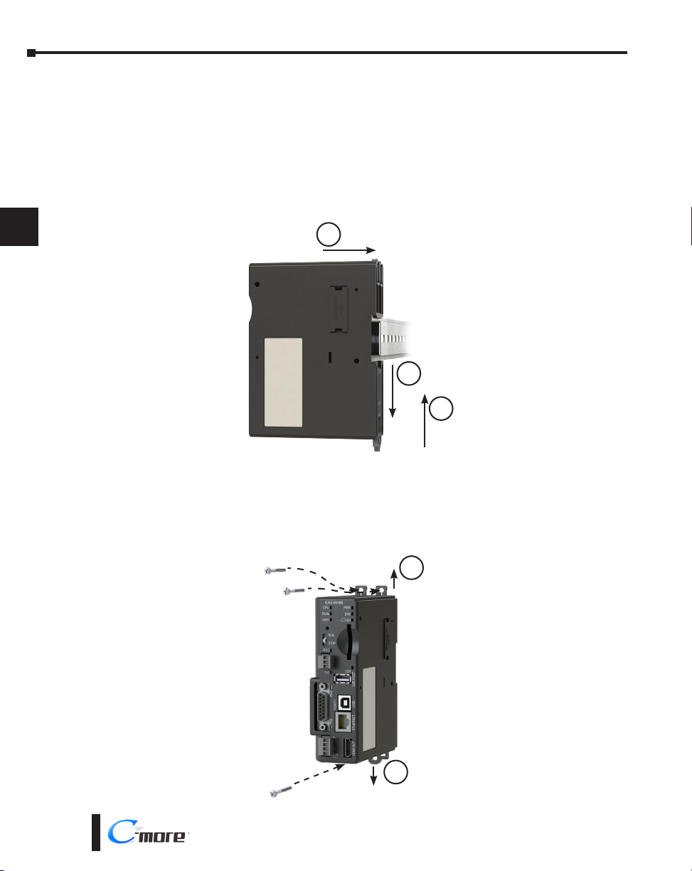
Chapter 4 - Installation and Wiring
Mounting
1
2
3
4
5
6
7
8
9
10
11
12
DIN Rail Mounting
EA9-RHMI can be mounted vertically on a standard 35mm x 7.5mm height DIN rail
(Standard: CENELEC EN50022).
1. Pull the bottom retaining tab of the EA9-RHMI down.
2. Position the EA9-RHMI on the DIN rail.
3. Push the retaining tab up until it clicks to secure the EA9-RHMI on the DIN rail.
2
1
3
Panel Mounting
EA9-RHMI can be mounted vertically on a panel using the tabs located on the back of the
unit.
1. Fully extend the three mounting tabs located on the top and bottom of the unit.
2. Secure to a panel using three #8 standard or M4 metric screws and appropriate hardware.
13
14
A
B
C
D
4-4
1
1
®
EA9-RHMI-USER-M Hardware User Manual, 1st Ed. Rev. G
Page 53

Chapter 4 - Installation and Wiring
CPU
RUN
USER
PWR
ERR
SD
RUN
STOP
PORT2PORT1
RXDTXD
USBETHERNET
HDMI OUT
USB
0V
12-24V
EA9-RHMI
RXD
TXD
Mounting Clearances
The following drawing shows the mounting clearances for the C-more RHMI. There should
be a minimum of 2 inches of space on top and sides and 3 inches on the bottom from the
nearest object or obstruction. There should also be a minimum of 1.75 inches of space in
front of the unit to allow for the bend radius of any cables attached.
1.75”
[44 mm]
2.0”
[51 mm]
2.0”
[51 mm]
[51 mm]
1
2
3
4
5
6
7
2.0”
8
9
10
11
3.0”
[76 mm]
12
13
14
A
EA9-RHMI-USER-M Hardware User Manual, 1st Ed. Rev. G
®
B
C
D
4-5
Page 54

Chapter 4 - Installation and Wiring
Wiring Guidelines
1
2
3
4
5
6
7
8
9
WARNING: To minimize the risk of potential safety problems, you should follow all applicable local
and national codes that regulate the installation and operation of your equipment. These codes vary
from area to area and it is your responsibility to determine which codes should be followed, and to
verify that the equipment, installation, and operation are in compliance with the latest revision of these
codes.
Equipment damage or serious injury to personnel can result from the failure to follow all applicable
codes and standards. We do not guarantee the products described in this publication are suitable for
your particular application, nor do we assume any responsibility for your product design, installation,
or operation.
If you have any questions concerning the installation or operation of this equipment, or if you need
additional information, please call technical support at 1-800-633-0405 or 770-844-4200.
This publication is based on information that was available at the time it was printed. At
Automationdirect.com® we constantly strive to improve our products and services, so we reserve
the right to make changes to the products and/or publications at any time without notice and without
obligation. This publication may also discuss features that may not be available in certain revisions of
the product.
Agency Approvals
Some applications require agency approvals for particular components. C-more agency
approvals are listed below:
• UL (Underwriters’ Laboratories, Inc.)
• cUL (Canadian Underwriters’ Laboratories, Inc.)
• CE (European Economic Union)
10
11
12
13
14
A
B
C
D
4-6
®
EA9-RHMI-USER-M Hardware User Manual, 1st Ed. Rev. G
Page 55

Wiring Guidelines (cont’d)
Providing Power to the HMI
• Connect a dedicated 12-24 VDC Class 2 power supply to the DC connector on the front of the
C-more EA9-RHMI, include wiring the ground terminal to a proper equipment ground
• Then turn on the power source and check the LED status indicators on the front of the C-more
EA9-RHMI for proper indication (see next page)
NOTE: A dedicated power supply is recommended. If the power supply also feeds inductive loads such as
solenoids or relays, the transients caused by these loads can affect the operation of the unit or damage HMI
components.
DC Power Wiring
Recommended Fuse
Rating ADC part number
2.5 A MDL2-5
Chapter 4 - Installation and Wiring
1
2
3
4
5
6
7
8
9
Equipment
Ground
0V
12- 24 VDC
Tightening Torque
Power supply cable torque 32-35 oz-in (0.22-0.25 Nm)
Warning: Use 60/75 °C copper conductors only.
EA9-RHMI-USER-M Hardware User Manual, 1st Ed. Rev. G
C0-4TB
Terminal Block
10
11
12
13
14
A
B
C
D
®
4-7
Page 56

Chapter 4 - Installation and Wiring
C-more LED Status Indicators
1
2
3
4
5
6
7
8
9
10
11
12
13
14
A
B
C
D
System Status LEDs
- CPU Green/Red/Orange
- RUN Green/Red/Orange
- USER Green/Red/Orange
Reset Button
RUN / STOP Switch
Receive Green
Port 2 Serial Port
Transmit Green
Receive Green
Port 1 Serial Port
Transmit Green
System Status LEDs
State
LED
Status Loading OS
CPU Running Normal
Project Loaded and Running
No User Project
Password Required
Errors Power Loss Detection
Memory Error
OS Error
Watch Dog Time Out
No Log Storage Found
General Error*
Warning*
Mode Recovery Mode
Safe Mode
*Note - See Chapter 8 - Troubleshooting for General Error and Warning explanations.
CPU RUN ERR
Blinking Green (0.5s) OFF OFF
Green – OFF
– Green –
– Orange –
– Blinking Orange (0.5s) Blinking Red (0.5s)
Blinking Orange (0.2s) – –
Red OFF Red
Blinking Orange (0.5s) OFF Red
Blinking Red (0.5s) – Red
– Blinking Orange (0.5s) Blinking Red (0.5s)
– Red (0.5s) Blinking Red (0.5s)
– Blinking Orange (0.5s) Blinking Red (0.5s)
Blinking Orange (0.5s) OFF OFF
Orange OFF Red
System Status LEDs
- PWR Green
- ERR Red
SD Status Green
USB Status Green
4-8
®
EA9-RHMI-USER-M Hardware User Manual, 1st Ed. Rev. G
Page 57

Chapter 4 - Installation and Wiring
Reset Button
Reset Button
Push Action Behavior Note
Push for <15 seconds Reboot the EA9-RHMI
Push for >15 seconds Reset to factory default The project is cleared and all settings are initialized.
Recovery tool installed with software and a USB
Hold down the button and
power on the EA9-RHMI
System recovery mode
connection is required to recover the panel.
The Error LED will be RED and the CPU LED will
blink ORANGE. See “No System Found” in Chapter
8 - Troubleshooting
1
2
3
4
RUN/STOP switch
RUN / STOP Switch
Position Behavior Note
RUN
STOP
Power on the EA9-RHMI
while in the STOP position
Project will run if present and the
RUN LED will be green
The project and any logging
stops and the System Screen is
displayed.
After the project is loaded into
memory the System Screen is
displayed
If no project is loaded in the HMI, the
message “No Program Found” will be
displayed. The RUN LED will blink orange.
If a password has been set up for the System
Screen, the RUN LED will blink orange.
A System Screen password is ignored.
User Defined LED
The user defined LED on the EA9-RHMI can be controlled from the project to illuminate
red, green or orange. It can also be configured to blink these colors. Refer to the online help
file provided with the programming software for details.
EA9-RHMI Beep
Beep Functions
Function Beep Pattern
Boot 1-long, 2-short
Boot Error* 3-long
HDMI Connected 3-short
Reset to Factory Defaults 14 short beeps progressively closer together followed by 1-long beep.
Blink Screen 5-long
*Boot Errors
Multiple Projects
Write Protected SD Card
No Log Storage Found
System Screen (RUN/STOP switch in STOP position)
Password Protected
5
6
7
8
9
10
11
12
13
14
A
B
C
D
EA9-RHMI-USER-M Hardware User Manual, 1st Ed. Rev. G
®
4-9
Page 58

Page 59

Chapter
Chapter
Chapter
SyStem Setup ScreenS
5
5
5
In This Chapter...
Introduction ...................................................................................................................5-2
Accessing the System Setup Screens ............................................................................5-3
With no project loaded ������������������������������������������������������������������������������������������������5-3
With project loaded������������������������������������������������������������������������������������������������������5-4
Using RHMI USB Remote ����������������������������������������������������������������������������������������������5-5
System Setup Screens – Enable Password in Software ................................................5-7
System Setup Screens Flowchart ................................................................................5-13
Main Menu...................................................................................................................5-14
Information Menu .......................................................................................................5-15
Setting Menu ...............................................................................................................5-19
Test Menu ....................................................................................................................5-25
Memory Menu .............................................................................................................5-35
Page 60

Chapter 5 - System Setup Screens
Introduction
1
2
3
4
5
6
7
8
9
10
11
The C-more EA9-RHMI includes a series of built-in System Setup Screens that allow
the user to view detailed information about the HMI; adjust certain features; configure
communications; test various functions of the HMI; backup and restore firmware, recipe, log
and project memory; clear memory and reset all values and conditions back to the original
factory defaults.
The four Main Menu selections are:
Information
The information tabs display details about the HMI model; the HMI’s
name; version information for the hardware, boot loader and firmware;
clock source, and beeper status. Other tabs display details on the
HMI’s internal memory and the status of any external memory devices.
Communication port details are available in this area, as well as an error log to help in
troubleshooting the system
Setting
This is the area for (1) making adjustments to the internal clock,
(2) setting the IP addresses (3) adjusting (calibrating) a connected touch
screen, (4) enabling or disabling the internal beep, and (5) enabling or
disabling a mouse pointer.
Test Menu
From this sub menu, the user can (1) test the a connected touch
screen, (2) test a connected display, (3) test the user LED (4) test the
communication ports, and (5) test both the internal beeper. A WAV
sound file is system provided for the audio output test.
12
13
14
A
B
C
D
5-2
Memory
Select the Memory menu item to either backup or restore your project,
log data, recipe data and/or system memory. Selections can be made to
backup to optional SD card memory or USB pen drive memory. The
menu selections also give the user the ability to clear the memory, and
there is also a selection to reset all of the HMI settings back to the original factory defaults.
®
EA9-RHMI-USER-M Hardware User Manual, 1st Ed. Rev. G
Page 61

Accessing the System Setup Screens
There are three ways to access the System Setup Screens in the EA9-RHMI.
1) On the HMI by moving the RUN/STOP switch to the STOP position
2) From a connected compatible touch screen using the Key Button Object
3) From the C-more Software and using the RHMI USB Remote utility
With no project loaded
To access the Main Menu of the HMI System Setup Screens prior to downloading a project,
move the RUN/STOP switch to the STOP position as shown below. If a display is attached
to the EA9-RHMI, the Main Menu will be displayed.
Chapter 5 - System Setup Screens
1
2
3
4
5
6
7
8
9
EA9-RHMI-USER-M Hardware User Manual, 1st Ed. Rev. G
10
11
12
13
14
A
B
C
D
®
5-3
Page 62

Chapter 5 - System Setup Screens
With project loaded
To access the Main Menu of the EA9-RHMI System Setup Screens with a project loaded into
1
memory, move the RUN/STOP switch to the STOP position.
2
3
4
5
6
7
8
9
10
11
12
13
14
A
B
C
If the RUN/STOP Switch is not accessible, a Key Button Object can be added to a screen
in the C-more HMI project to access the System Screens. See the C-more Programming
Software Help File Topic, “Key Button Object” for more information.
If the Key Button is used and no system screen password is enabled, the following
WARNING dialog box will appear on the connected screen:
• Pressing OK will display the system setup screen.
See the WARNING below!
System Screen Called
Activating System Screen will stop the
WARNING: This will STOP the PLC driver and therefore all communications between the EA9-RHMI
and PLC will cease. In addition, moving the RUN / STOP switch to the STOP position does not
display this warning. This is why it is strongly recommended that the password system tag “SYS
SYSTEMSCREENPW” be enabled to add a safeguard step in accessing the system setup screens. See
the next section for an overview of how to set the System Tags in the Event Manager Database.
Panel Run Mode.
Do you want to continue?
CancelOK
• Pressing Cancel will take you back to the project screen.
• Communication with the PLC is active while the
Warning is displayed.
• The dialog box will close if no action is taken for 60
seconds.
• The dialog box will not display if the HMI does not have
a project loaded.
• The dialog box will display after a valid password is
entered if the System Screen password is enabled.
D
5-4
®
EA9-RHMI-USER-M Hardware User Manual, 1st Ed. Rev. G
Page 63
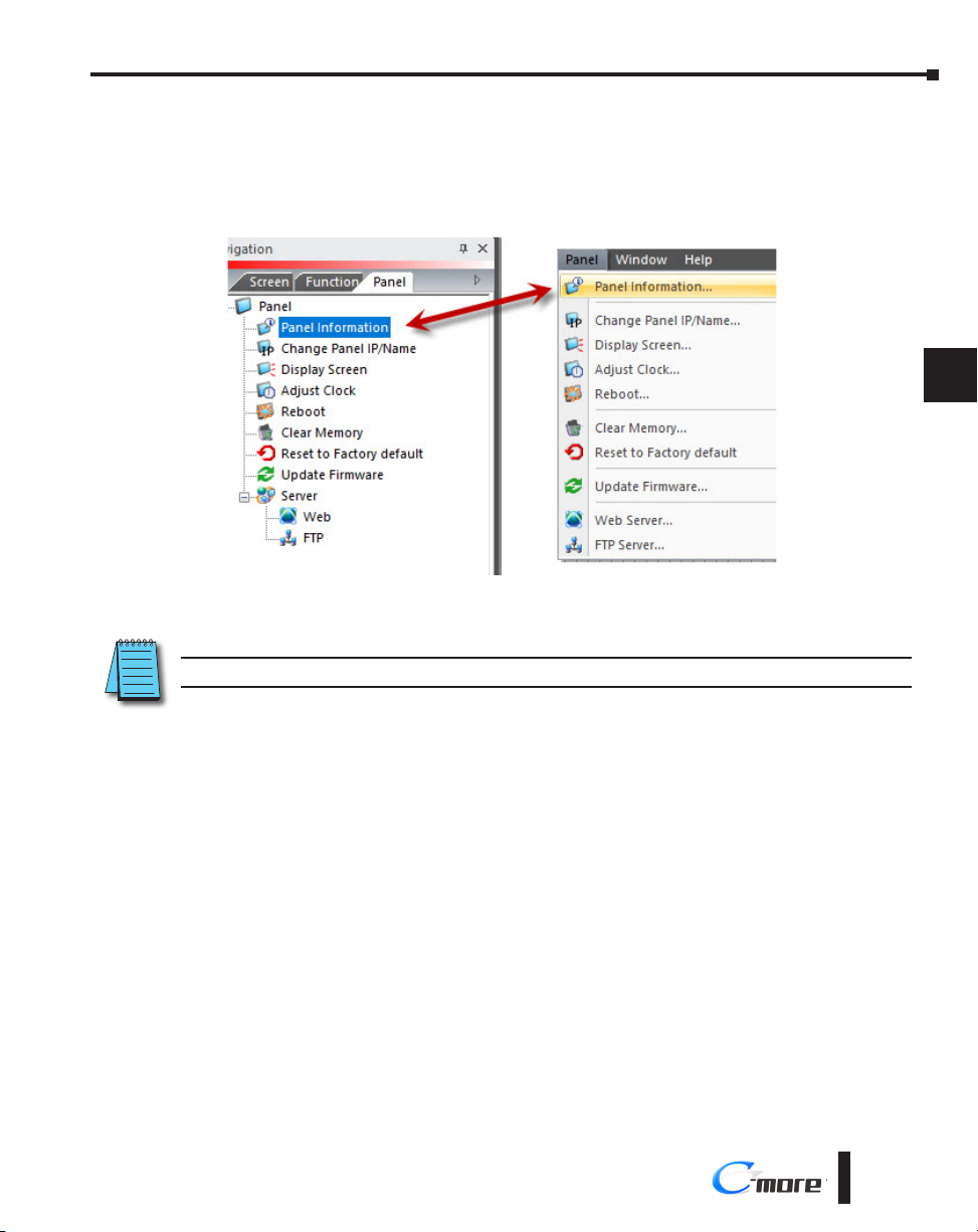
Chapter 5 - System Setup Screens
Using RHMI USB Remote
Another option for seeing the System Screens is through a PC connected by USB to the
EA9-RHMI.
In the C-more programming software, double click Panel Information in the Panel tab on the
navigation window as shown below or select Panel Information in the Panel menu.
1
2
3
4
5
6
7
8
Select RHMI USB Remote. The RHMI USB Remote displays the same screen that is shown
on a connected HMI monitor.
NOTE: The RHMI USB Remote selection is only available if the panel is connected to the PC by a USB cable.
EA9-RHMI-USER-M Hardware User Manual, 1st Ed. Rev. G
®
5-5
9
10
11
12
13
14
A
B
C
D
Page 64

Chapter 5 - System Setup Screens
Select Enable Panel Operation. This allows the screens to be clicked with a mouse and
operated as if you were touching a touch screen connected to the HMI.
1
2
If the HMI’s RUN/STOP Switch is in the RUN position, you can select STOP under Panel
Switch Position to see the System Screen. If the Switch is in the STOP position already, the
System Screen will already be displayed.
For more information see the Help File topic Panel Tab - Panel Information.
3
4
5
6
7
8
9
10
11
12
13
14
A
B
C
D
5-6
®
EA9-RHMI-USER-M Hardware User Manual, 1st Ed. Rev. G
Page 65

Chapter 5 - System Setup Screens
System Setup Screens
Clicking the OK button will open the Main Menu as shown below. You can then proceed to
the other system setup screens.
1
2
3
4
5
6
Password Protecting System Screen Access
NOTE: If the password system tag SYS SYSTEMSCREENPW is enabled, the Enter Security Code keypad shown
below will open. The procedure to enable the SYS SYSTEMSCREENPW is detailed below.
Entering the correct password will display the HMI Run Mode warning dialog described previously. PLC
communications continue while the keypad is displayed. The keypad will timeout after 60 seconds.
Enter Security Code
987
654
321
CL0–
Enter
Cancel
7
8
9
10
11
12
13
14
A
B
C
EA9-RHMI-USER-M Hardware User Manual, 1st Ed. Rev. G
D
®
5-7
Page 66

Chapter 5 - System Setup Screens
System Setup Screens – Enable Password in Software
1
2
3
4
5
6
7
8
9
10
11
Under the C-more Programming Software’s Navigation window, select the Function tab, then
double click on “Alarm Action” to display the Event Manager Database shown below:
Click on the Add button
to add an event to the
database that will be used
to enable the System
Screen Password.
1
2
12
13
14
A
B
C
D
5-8
®
EA9-RHMI-USER-M Hardware User Manual, 1st Ed. Rev. G
Page 67

Chapter 5 - System Setup Screens
System Setup Screens – Enable Password (cont’d)
The Event Add dialog box will be displayed as shown.
1
2
3
4
Click on the Tag Name: pull down menu and select the internal System Bit On
(SYS BIT ON) tag as shown. This will force the tag event type to be continuously active.
3
4
Tag Name: SYS BIT ON
5
6
7
8
9
10
11
12
13
14
A
EA9-RHMI-USER-M Hardware User Manual, 1st Ed. Rev. G
B
C
D
®
5-9
Page 68

Chapter 5 - System Setup Screens
System Setup Screens – Enable Password (cont’d)
1
2
3
4
5
6
7
8
9
10
11
Use the Event Name: text box to document the event as “System Screen PW” for record
keeping This is optional.
In the Action box, click once on the displayed 01-Alarm under the Sequence List: so that
01-Alarm is highlighted. Then click the Delete Action button to remove the 01-Alarm.
Event Name:
5
Delete Action
12
13
14
A
B
C
D
5-10
6
The Sequence List will
now be cleared out.
®
EA9-RHMI-USER-M Hardware User Manual, 1st Ed. Rev. G
Page 69

Chapter 5 - System Setup Screens
System Setup Screens – Enable Password (cont’d)
In the Action box, click on the Add Action... button. This will bring up the Add Action
dialog box as shown below:
1
2
3
4
7
Click on the Tag button.
8
Add Action
Tag
5
6
7
8
9
10
11
12
13
14
A
EA9-RHMI-USER-M Hardware User Manual, 1st Ed. Rev. G
®
B
C
D
5-11
Page 70

Chapter 5 - System Setup Screens
System Setup Screens – Enable Password (cont’d)
1
A 01-Tag action item will then be added to the Sequence List.
2
3
4
9
5
6
7
8
9
Click on the Tag Name: pull down list down arrow in the Action box’s Tag tab, select
10
SYS SYSTEMSCREENPW from the list, and click OK.
01-Tag
11
12
13
14
A
B
C
D
5-12
10
SYS SYSTEMSCREENPW
®
EA9-RHMI-USER-M Hardware User Manual, 1st Ed. Rev. G
Page 71

Chapter 5 - System Setup Screens
System Setup Screens – Enable Password (cont’d)
Enter a numeric value into the Value: box, such as “777”. This value becomes the Password
code to access the System Setup Screen’s Main Menu.
11
Click the Add button in the Event Add dialog box and then the Close button to return to
the Event Manager Database. You now will see that the first event in the database is for the
System Screen Password and it is enabled.
Password Value – 777
1
2
3
4
5
6
7
8
9
10
11
12
EA9-RHMI-USER-M Hardware User Manual, 1st Ed. Rev. G
®
12
13
14
A
B
C
D
5-13
Page 72

Chapter 5 - System Setup Screens
System Setup Screens Flowchart
1
2
3
4
5
6
7
8
9
10
11
Main Menu
Information
Setting Adjust Clock
Test Menu
General/Memory/Ethernet/
Error
IP Address Setting
Adjust Touch Panel
(Touch Screen Calibration)
Beep
Mouse
Test Touch Panel
Test Display
Test User LED
12
13
14
A
B
C
D
5-14
Test Communication Port
Test Beep/Sound
Memory
®
EA9-RHMI-USER-M Hardware User Manual, 1st Ed. Rev. G
Backup
Restore
Clear Memory
Reset to Factory Default
Page 73

Main Menu
Chapter 5 - System Setup Screens
The Main Menu system setup screen is the top layer in
the menu structure.
1
2
3
4
5
6
7
8
9
EA9-RHMI-USER-M Hardware User Manual, 1st Ed. Rev. G
®
10
11
12
13
14
A
B
C
D
5-15
Page 74

Chapter 5 - System Setup Screens
Information Menu
1
2
3
4
5
6
7
8
9
10
11
12
13
14
A
B
C
D
Information - General tab
1
2
The General tab under the Information
menu provides detailed information about
the C-more HMI.
3
4
5
8
6
7
Item No. Function Description Comments
EA9-T6CL-R
EA9-T6CL
EA9-T7CL-R
EA9-T7CL
EA9-T8CL
1 Panel Type
2 Panel Name
3 Version
4 Clock
5 Beep
6 Project Boot Storage
7 HDMI
8 Main Menu
EA9-T10CL
EA9-T10WCL
EA9-T12CL
EA9-T15CL-R
EA9-T15CL
EA9-RHMI
The panel name is configured in the
programming software and saved with a
project.
The version identifications provide
information on the components and
firmware in the panel
Internal/External clock selection.
Status of the internal beeper.
The location of the current project. Built-in flash, SD1
HDMI connection to an external screen.
Only models with HDMI port
Press to return to the Main Menu screen.
Model Number
The default panel name is the model
number plus the lower three bytes
of the panel MAC address, i.e. EA9T8CL-0022C4.
Files reside in the C-more HMI’s
memory.
Configured in the C-more
Programming Software.
Configurable in the Setting Menu –
Beeper shown on page 5-23 or in
the C-more Programming Software.
Connected, Not connected
Main Menu shown on previous
page.
5-16
®
EA9-RHMI-USER-M Hardware User Manual, 1st Ed. Rev. G
Page 75

Information - Memory tab
1
Chapter 5 - System Setup Screens
1. Memory components - Status of each memory
component - SDRAM, MRAM and Built-in Flash
are internal memory components. When external
memory devices are installed in the panel they will be
included in this list : SD and USB.
1
2
3
4
2
3
2. Resource Monitor - Selecting Resource Monitor
displays the CPU and runtime memory usage
percentage. This window will remain open after
exiting from the system screen. This allows for
monitoring the panel resources while the project
is running. Pressing the Error List button expands
the window to show the PLC communication error
list in real time. Press OK once to remove the Error
List. Press OK again to close the Resource Monitor
window.
3. Main Menu - Press to return to the Main Menu
screen - Main Menu shown previously
5
6
7
8
9
10
11
12
13
14
A
EA9-RHMI-USER-M Hardware User Manual, 1st Ed. Rev. G
®
B
C
D
5-17
Page 76

Chapter 5 - System Setup Screens
Information - Ethernet tab
1
2
3
4
5
6
7
8
9
10
11
12
13
14
1
3
2 4
Item No. Function Description Comment
Ethernet Settings:
MAC Address: 00 D0 7C XX XX XX
Ethernet
1
(Link: Online)
2 Option Unit
Option
3
(Link Online)
4 Main Menu
Address Type: DHCP/Static
IP Address:
Subnet Mask:
Default Gateway:
DNS: 1) Automatically
2) Use Designated Address
Opens Ethernet settings for optional
EA-ECOM if connected.
Ethernet Settings:
MAC Address: 00 D0 7C XX XX XX
Address Type: DHCP/Static
IP Address:
Subnet Mask:
Note: Option Unit uses the same Default
Gateways as Item 1 - Ethernet
Press to return to the Main Menu screen.
Configurable in the Setting Menu
– IP Address Setting shown in
this section or in the C-more
Programming Software.
A
B
C
D
5-18
®
EA9-RHMI-USER-M Hardware User Manual, 1st Ed. Rev. G
Page 77

Information - Error tab
Chapter 5 - System Setup Screens
21 3 4 5
Error message format
Navigation buttons
6 7 8
21 3 4
Error Message Format:
Item No. Function Description Comment
Order of error message functions:
Error Number, Date, Time, Error Port, Device Name, Error Type, PLC Address, Access Bytes, Error Message
1 Date
2 Time
3 Error Port
4 Device Name
5 Error Type
6 PLC Address
7 Access Bytes
8 Error Message
Error Message navigation buttons:
Format: MM/DD/YY Date error occurred.
Format: HH/MM/SS Time error occurred.
PLC Serial Communications Port:
Ethernet:
The name of the device reporting the error.
RD: Read
WT: Write
The assigned address of the PLC that caused
the error.
The number of access bytes.
The error message is the same as the
message displayed in the upper left of the
C-more HMI’s connected display.
Device names are configured in the
programming software, Panel Manager
A list of Error Massages is shown in
Appendix A
1
2
3
4
5
6
7
8
9
10
11
12
13
14
Item No. Function Description Comment
1 Clear
2 Page Down
3 Page Up
4 Main Menu
EA9-RHMI-USER-M Hardware User Manual, 1st Ed. Rev. G
Press to clear all error messages. This
button is grayed out when there are no error
messages to display.
Press to go to the next page. This button is
grayed out when there is no error messages
on the next page.
Press to go to the previous page. This
button is grayed out when there is no error
messages on the previous page.
Press to return to the Main Menu screen.
Errors are also cleared with firmware is
updated on the panel. Errors are not cleared
on power cycle or project transfer.
®
A
B
C
D
5-19
Page 78

Chapter 5 - System Setup Screens
Setting Menu
1
2
3
1
4
The Setting Menu is used to adjust the time & date,
adjust the contrast or brightness of the display, enter
the IP address settings, adjust (calibrate) the connected
touch screen, enable or disable the internal beep and
turn on and off the mouse cursor .
2
5
6
7
8
9
10
11
12
13
14
A
3 4
5
6
Item No. Function Description Comments
1 Adjust Clock
2 IP Address
3 Adjust Touch Panel
4 Beep
5 Mouse
6 Main Menu
Press to go to the Adjust Clock screen.
Press to go to the IP Address screen
Press to go to the Adjust Touch Panel screen.
Press to go to the Beep screen.
Press to go to the Mouse screen.
Press to return to the Main Menu screen.
The IP Address can also be set from
the programming software or by the
project.
B
C
D
5-20
®
EA9-RHMI-USER-M Hardware User Manual, 1st Ed. Rev. G
Page 79

Setting – Adjust Clock
1
2
3
Chapter 5 - System Setup Screens
1
2
3
4
4
Item No. Function Description Comments
1 Select
2 Up
3 Down
4 OK
5 Cancel
NOTE: The function buttons used to adjust the clock settings on the panel’s setup screen are disabled if an
External clock source is selected in the C-more programming software. The choice of an internal or external clock
source is available by selecting Clock Source in the C-more programming software under the Main Menu drop
down function Setup.
NOTE: The panel’s clock can also be adjusted from the C-more programming software. The Adjust Clock function
can be accessed in the software by selecting Adjust Clock under the Main Menu drop down function Panel or
selecting Adjust Clock under the Panel tab in the software’s Navigation window.
5
Time: Each press of the Select button will
cycle thru the following settings.
1) No Selection to Hours
2) Hours to Minutes
3) Minutes to Seconds
4) Seconds back to Hours
Date: Each press of the Select button will
cycle thru the following settings.
1) Month to Day
2) Day to Year
3) Year back to Month
Press to increment the value by “1” with
each press.
Press to decrement the value by “1” with
each press.
Press to accept the changes.
Press to return to the Setting Menu screen
without accepting the changes.
5
6
7
8
9
10
11
12
13
14
A
B
C
EA9-RHMI-USER-M Hardware User Manual, 1st Ed. Rev. G
®
D
5-21
Page 80

Chapter 5 - System Setup Screens
Setting – Adjust Touch Panel
A compatible touch screen can be attached to the EA9-RHMI through the USB Type A port.
1
2
This procedure is used to calibrate a connected touch screen to ensure accuracy of the touch
areas. There are three points on the touch screen that the calibration is based around. The
adjustment relies on very narrow areas for the calibration points.
3
4
5
6
7
8
9
10
11
12
13
3a
1
2
Item No. Function Description Comment
1 Start Calibration
2 Cancel
3 Points 3a thru 3c
Press to begin the touch screen calibration
Press to return to the Setting Menu screen.
The touch screen calibration crosshairs will
appear individually in the order of point 3a
thru 3c respectively as each proceeding
crosshair is pressed.
Once all three points are touched,
select Accept, Redo or Cancel.
3c
3b
14
A
B
C
D
5-22
®
EA9-RHMI-USER-M Hardware User Manual, 1st Ed. Rev. G
Page 81

Setting – Beep
Chapter 5 - System Setup Screens
This system setup screen function is used to enable or
disable the HMI’s internal beep function.
1
2
1
2
Item No. Function Description Comments
1 Enable Beep
2 OK
3 Cancel
NOTE: The project settings in the C-more programming software Panel Manager will override the HMI’s internal
setting upon initial download.
3
Check to enable the internal beep.
Press to accept the changes.
Press to return to the Setting Menu screen
without accepting the changes.
3
4
5
6
7
8
9
10
11
12
13
EA9-RHMI-USER-M Hardware User Manual, 1st Ed. Rev. G
®
14
A
B
C
D
5-23
Page 82

Chapter 5 - System Setup Screens
Setting – Mouse
1
2
3
4
This system setup screen function is used to enable/
disable the arrow mouse cursor on the connected screen.
It may be valuable to display the mouse cursor, for
example, when an external USB keyboard is connected
to the panel. The mouse cursor is enabled by default
when the EA9-RHMI panel is the panel used for a
project.
5
6
7
8
9
10
11
12
13
14
A
5
NOTE: The project settings in the C-more programming software Panel Manager will override the HMI’s internal
setting upon initial download.
B
C
D
5-24
®
EA9-RHMI-USER-M Hardware User Manual, 1st Ed. Rev. G
Page 83

Setting – IP Address Setting
1
3
Chapter 5 - System Setup Screens
1
2
3
2
4
5
7
6
Item No. Function Description Comment
“DHCP” is enabled as the default when this
1 DHCP
2 IP Address
IP Address
3
Subnet Mask
Default Gateway
4 Keypad
5 IP Address (Option unit)
6 OK
7 Cancel
system setup screen is first selected.
All of the other selections on this screen are
dimmed when “DHCP” is selected and are
not available.
The “Use the following IP Address” setting is
selected when its radio button is pressed.
Use the numerical keypad to assign the IP
address.
Select the field that needs to be assigned by
touching the entry value and use the keypad
to enter the desired address.
The keypad is used to enter the Address:
Use the numeric keys to enter the address,
e.g: 192.168.10.1
“CL” = Clear value entered
Opens Ethernet settings for optional
EA-ECOM if connected.
Press to accept the changes and return to the
Setting Menu screen.
Press to return to the Setting Menu screen
without accepting the changes.
Note: If an Ethernet cable is not
connected to the HMI from an
active Ethernet device, then the IP
Address will show as 0.0.0.0.
Each field can be independently
assigned.
4
5
6
7
8
9
10
11
12
13
14
NOTE: The project settings in the C-more programming software Panel Manager will override the HMI’s internal
setting upon initial download.
EA9-RHMI-USER-M Hardware User Manual, 1st Ed. Rev. G
®
A
B
C
D
5-25
Page 84

Chapter 5 - System Setup Screens
Test Menu
1
2
The Test Menu gives the user the ability to test the
operation of a connected touch screen, test the LCD
display, test the various communication ports, and also
test the internal beeper.
3
4
5
6
7
8
9
10
11
12
13
1
4
2
5
3
6
Item No. Function Description Comments
1 Test Touch Panel
2 Test Display
3 Test User LED
4 Test Communication Port
5 Test Beep/Sound
6 Main Menu
Press to go to the Test Touch Panel screen.
Press to go to the Test Display screen.
Tests the user configurable LED on the front
of the panel.
Refer to the online help file for details on the
configuration of this LED.
Press to go to the Test Communication Port
screen.
Press to go to the Test Beep/Sound screen.
Press to return to the Main Menu screen.
14
A
B
C
D
5-26
®
EA9-RHMI-USER-M Hardware User Manual, 1st Ed. Rev. G
Page 85

Test Menu – Test Touch Panel
1
2
Chapter 5 - System Setup Screens
Using this test, normal or unusual
operation of the connected analog touch
screen can be determined.
Testing:
If an area of the touch screen is suspected
to be inoperable, touch that area of the
screen while in the Test Touch Panel
screen mode. The screen pixels should
turn black in that area. If the screen pixels
do not turn black when touched, then
the touch screen is defective or needs to
be calibrated. See Setting - Adjust Touch
Screen
1
2
3
4
5
6
7
Item No. Function Description Comments
1 Touch area
2 Cancel
NOTE: The touch screen driver is designed to respond to a single touch. If it is touched at multiple points at the
same time, an unexpected object may be activated.
Touch to turn on pixels on the screen.
Press to return to the Test Menu screen.
Both the title bar (Test Touch Panel)
and Cancel button can be drawn
across to test the touch operation.
8
9
10
11
12
13
14
A
B
C
D
EA9-RHMI-USER-M Hardware User Manual, 1st Ed. Rev. G
®
5-27
Page 86

Chapter 5 - System Setup Screens
Test Menu – Test Display
1
2
3
4
5
6
7
8
9
10
11
12
13
14
A
B
1) Test LCD
There are two different test patterns that may be run on the display to allow the user to check
for display screen defects. If an attached touch screen is not touched or a connected mouse is
not clicked within 3 seconds of Test Pattern 1 being displayed, then Test Pattern 2 will be
displayed until the screen is touched or a connected mouse is clicked, otherwise Test Pattern
1 will remain until cancelled.
Test Pattern 1 displays a test pattern of 16 grayscale graduations and RGB colors.
1
2
C
D
5-28
®
EA9-RHMI-USER-M Hardware User Manual, 1st Ed. Rev. G
Page 87

Chapter 5 - System Setup Screens
Test Pattern 2 will follow the pattern as shown in the following chart with the color wiping
across the screen in the direction indicated by the arrows, then repeats:
Color 1st Time 2nd Time 3rd Time 4th Time
1
RED
3
GREEN
BLUE
Item No. Function Description Comments
Touch the Test Display
1
screen
2 Cancel (Test Pattern 1)
Touch Anywhere
3
(Test Pattern 2)
Test Results: If any pixels on the screen do not appear the same color as the surrounding
pixels, the screen may be defective.
2) Check Available Resolutions on External HDMI Display
This selection performs a check through the HDMI port and attempts to negotiate with a
connected display and determine all available resolutions.
NOTE: If the display is connected through a signal converter such as an HDMI-DVI converter, the negotiations may
not be sucessful and the available resolutions may not be correct.
Press the screen anywhere except the
Cancel button and the shown Test Pattern 1
remains.
Press to return to the Test Menu screen.
Touch the sceen anywhere during Test
Pattern 2 and return to the Test Menu
screen.
If the Test Display screen is not
touched, then in three seconds the
display will move to Test Pattern 2.
2
3
4
5
6
7
8
9
10
11
12
EA9-RHMI-USER-M Hardware User Manual, 1st Ed. Rev. G
®
13
14
A
B
C
D
5-29
Page 88

Chapter 5 - System Setup Screens
1
15
15-pin D-sub
(male)
2
3
TXD
RXD
7
8
CTS
RTS
RS-232 Loop-back Connector
Wiring Diagram
1
15
15-pin D-sub
(male)
7
8
CTS
RTS
9
11
RXD+
TXD+
10
12
RXD–
TXD–
RS-422/485 Loop-back Connector
Wiring Diagram
Test Menu – Test Communication Ports: Serial Ports
1
2
1
3
4
The following test can be used to check the operation
of the serial communication ports, with the use of
a loop back connector and can also check the serial
2
communications to any connected and configured PLC.
5
6
7
8
9
10
11
12
13
14
A
3
Item No. Function Description Comments
The loop back test may be performed
on Serial Port 1 or Serial Port 3. Each
tab shows diagrams to assist the user
in building the loop back connector.
The PLC must be configured for
the selected port in the C-more
programming software Panel
Manager and transferred to the HMI
before attempting the PLC Enquiry
test.
1 Loop Back Test
2 PLC Enquiry Test
3 Cancel
Serial Port 1
The loop back test checks the hardware
components of the selected port for proper
operation.
This function allows the ability to select any
PLC that that may be connected to the HMI
via a serial connection and checks to see if
the communications are working correctly.
Press to return to the Test Menu screen.
B
C
D
5-30
®
EA9-RHMI-USER-M Hardware User Manual, 1st Ed. Rev. G
Page 89

Chapter 5 - System Setup Screens
Test Menu – PLC Serial Comm Port – Loop Back Test
Test Results
1.) Bytes Sent:
The number of bytes sent after a test is started.
2.) Receive Counts:
The number of bytes which are received after the test is started.
3.) Error Counts:
The number of bytes which have not been received after the test is started.
4.) RTS/CTS Test: Pass/Fail
RTS is turned on and if CTS receives the signal then the test shows “Pass,” otherwise the
test shows “Fail.”
NOTE: The test will continue to run until the Cancel button is pressed. If there are any error counts, check the loop
back connector.
1
2
3
4
5
6
7
8
9
10
11
12
13
14
A
B
C
D
EA9-RHMI-USER-M Hardware User Manual, 1st Ed. Rev. G
®
5-31
Page 90

Chapter 5 - System Setup Screens
Test Menu – PLC Enquiry Test: Serial Connection
1
2
3
4
5
6
PLC Enquiry Test
7
Four test packets are sent to the selected PLC. The test result with return either Pass or Fail.
8
9
This function allows the ability to select any PLC that
may be connected to the HMI through the selected
serial comm port connection and checks to see if the
communications are working correctly.
NOTE: The communications protocol for the PLC
being selected must be configured the same as the
C-more HMI. The HMI’s PLC serial communications
are configured using the C-more Programming
Software’s Panel Manager.
10
11
12
13
14
A
B
C
D
5-32
®
EA9-RHMI-USER-M Hardware User Manual, 1st Ed. Rev. G
Page 91

Chapter 5 - System Setup Screens
Test Menu – Test Communication Ports: Ethernet
The following test feature can be used to check the
operation of the Ethernet communication port by
indicating if an Ethernet link has been established
2
1
3
Item No. Function Description Comments
This area displays information on whether
or not an Ethernet link has been established
1 Ethernet Connected
2 PLC Enquiry Test
3 Cancel
Example of displayed message when the HMI’s Ethernet port
is not connected. Note that the address resets to 0.0.0.0
even if it has previously been entered.
for the HMI’s Ethernet comm port. Displays
panel’s IP address and shows whether it is
static or assigned by a DHCP server.
This function allows the ability to select
any PLC configured in the project that may
be connected to the HMI via an Ethernet
connection and checks to see if the
communications are working correctly.
Press to return to the Test Menu screen.
or not. It can also check the status of the Ethernet
communications to any connected PLC.
Base featured models (-R) do not include an Ethernet
port. Therefore, this check is not displayed on -R
models.
NOTE: The communications protocol for the PLC
being selected must be configured the same as the
C-more HMI. The HMI’s PLC serial communications
are configured using the C-more Programming
Software’s Panel Manager...
The PLC must be configured for
the selected port in the C-more
programming software Panel
Manager and transferred to the panel
before attempting the PLC Enquiry
test.
1
2
3
4
5
6
7
8
9
10
11
12
Typical Ethernet connection
with Ethernet switch
CLICK PLC
Ethernet CAT5
Cable
EA9-RHMI-USER-M Hardware User Manual, 1st Ed. Rev. G
Stride™
Ethernet Switch
10/100 Base-T
(such as SE2-SW5U)
EA9-RHMI
Auto MDI / MDI-X
Ethernet Port
C-more
®
13
14
A
B
C
D
5-33
Page 92

Chapter 5 - System Setup Screens
Test Menu – PLC Enquiry Test: Ethernet Connection
1
2
3
2
1
4
This function allows the ability to select any PLC
configured in the project that may be connected to the
HMI through an Ethernet port connection and checks
to see if the communications are working correctly.
NOTE: The communications protocol for the PLC
being selected must be configured the same as the
C-more HMI. The HMI’s PLC serial communications
are configured using the C-more Programming
Software’s Panel Manager.
5
6
7
8
9
10
11
12
13
14
A
3
PLC Enquiry Test
Following are the steps that the Ethernet PLC Enquiry Test performs:
1) Ping the network 4 times for the PLC selected.
2) Four of the test read packets are sent to the selected PLC.
The test result will either be Pass or Fail. However, if the result of pinging the network shows
an error, the test is stopped.
B
C
D
5-34
®
EA9-RHMI-USER-M Hardware User Manual, 1st Ed. Rev. G
Page 93

Test Menu – Test Beep/Sound
Chapter 5 - System Setup Screens
The internal Beeper can be tested from this system
setup screen whether the Beeper is enabled or disabled.
After the Beep Test button is pressed and released, the
Beeper will sound for 500 msec.
1
2
1
2
3
4
5
6
7
8
9
10
11
12
13
EA9-RHMI-USER-M Hardware User Manual, 1st Ed. Rev. G
®
14
A
B
C
D
5-35
Page 94

Chapter 5 - System Setup Screens
Memory Menu
1
2
3
1
4
2
The user’s project, Firmware and OS, log and recipes
files can be backed up to or restored from an SD
memory card or a USB memory device. From this menu
the user can also clear the project log files. The user also
has the ability to clear the memory within the C-more
HMI.
5
6
7
8
9
10
11
12
13
14
A
B
C
D
3
4
5
Item No. Function Description Comments
Any USB 2.0 pen drive.
SD formats SD and SDHC are
supported. Capacity up to 32GB.
Backup project, Firmware and OS, log &
1 Backup
2 Restore
3 Clear Memory
4 Reset to Factory Default
5 Main Menu
NOTE: The Project is RESTORED to the panel from an external memory device. A project can be TRANSFERRED
to an SD card or USB memory from the programming software to be RESTORED to a panel that is not connected
to the programming software. This file has the .eas9 extension NOT the .eap9 extension of a projects SAVED from
the software.
recipe files to the following memory devices:
USB port - Type A: USB pen drive
SD Card Slot: SD card
Restore project, Firmware and OS, log &
recipe files to the internal memory from one
of the following memory devices:
USB port - Type A: USB pen drive
SD Card Slot: SD card
Clear selected data files from the memory
of the following internal memory or external
memory devices:
Built-in FLASH Memory
USB port - Type A: USB pen drive
SD Card Slot: SD card
The HMI’s internal memory is set to the
original factory defaults.
Press to return to the Main Menu screen.
The backup data files are created and
copied to a folder on the memory device
named “EA_Memory Copy.”
The project file is named
StartupStorage.eas9
“Log” and “Recipe” folders with the
appropriate data files are also created on
the memory device.
A folder on the memory device named
“EA_Memory Copy” must exist
containing a file named “StartupStorage.
eas9”. The project data file is stored
in this file, and if the system data file
was backed up, it also will be stored in
this file. Any backed up log or recipe
data files will be located under the
appropriate “Log” or “Recipe” folders.
Can only clear project, log and recipe
data files of the Built-in FLASH memory.
Can clear entire contents or individual
data files of external memory devices.
Clears all project memory.
5-36
®
EA9-RHMI-USER-M Hardware User Manual, 1st Ed. Rev. G
Page 95

Chapter 5 - System Setup Screens
Project Executed from SD Card Slot 1
If the Project Storage/Boot Location is set to Auto or SD1 in the C-more software Panel
Manager, and an SD memory card is located in the SD Card Slot 1 at the time a project is
transferred to the panel, the project will be stored on the SD card and the Internal Project
Memory will be cleared.
If Slot 1 contains an SD memory card with a project and the HMI’s power is cycled, then the
project file stored on the SD card is loaded into the HMI’s internal memory and executed.
Any project in the internal FLASH memory is cleared.
1
2
3
WARNING: During power up with an SD memory card plugged into an SD card slot, do not remove the
memory card from the slot. Damage to the SD memory card and possibly the HMI may result.
WARNING: After a firmware update, the project files which are located in either the HMI’s internal
FLASH memory or an SD memory card plugged into an SD card slot are cleared. The programming
software will need to be used to transfer the project file back into the panel. If you wish to retain the
project on the SD memory card, power down the HMI and remove the SD card before performing a
firmware upgrade.
Increasing Project Memory Size using an SD memory card:
If a project is transferred to the panel with an SD memory card in SD slot 1, the Font and
Recipe data files are not included in the 82MB project size. Therefore using an SD memory
card can allow a project to be loaded that is larger than 82MB if the excessive size is caused by
Fonts and/or Recipe Sheets.
4
5
6
7
8
9
10
11
12
13
14
EA9-RHMI-USER-M Hardware User Manual, 1st Ed. Rev. G
®
A
B
C
D
5-37
Page 96

Chapter 5 - System Setup Screens
Memory – Backup
1
2
3
4
5
The Memory - Backup selection allows you to backup
the panel’s Project, Log files, Recipe files or even
the Firmware files to either an SD memory card or
USB pen drive. The available memory devices will be
displayed with their total and free memory.
If the device is not available, it will be grayed out. The
Next button is grayed out until a device is selected.
The Cancel button can be pressed at any time to return
to the Memory Menu screen.
6
7
8
9
10
11
12
13
14
A
B
This is an example of selecting a USB memory device to
write the backed up files to.
The selected device is highlighted. Pressing again
deselects it.
Even if there is only one available memory device, it still
needs to be highlighted in order to go to the next step.
Press the Next button to continue to Step 2.
Please read the explanation for the availability of SD1 under different conditions that follow:
C
D
5-38
®
EA9-RHMI-USER-M Hardware User Manual, 1st Ed. Rev. G
Page 97

Memory – Backup (cont’d)
Chapter 5 - System Setup Screens
SD Card Slot1 Availability Explanation:
SD1 may be unavailable (grayed out) if there is no card
in SD Slot 1 or the card in SD slot 1 has the project
currently running on the panel stored on it.
The project will exist on SD1 if the SD card
was installed in SD1 when the project was
TRANSFERRED to the panel by the C-more
programming software.
If the panel is powered up or rebooted with an SD card
inserted into SD1 Slot, then the SD1 button’s Total
and Free memory will be displayed.
1
2
3
4
5
6
7
8
9
10
11
EA9-RHMI-USER-M Hardware User Manual, 1st Ed. Rev. G
®
12
13
14
A
B
C
D
5-39
Page 98
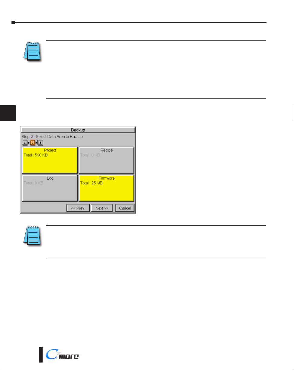
Chapter 5 - System Setup Screens
Memory – Backup (cont’d)
NOTE: The following definitions are for the various file types that can be backed up:
1
2
3
4
Project data – consists of the actual developed project data that is created in the C-more programming software
and includes all functionality, objects, screens, tag names, labels, comments, graphics, etc. Included in backup file
name StartupStorage.eas9.
Recipe data – consists of all the data values and labels that have been created for the various recipe sheets.
Includes all recipe sheets loaded to the panel. Only recipe sheets used in the project are loaded to the panel.
Firmware – consists of the operating system, firmware and run time files. Included in backup file name
StartupStorage.eas9.
Log data – consists of the Alarm Log, Message Log and Trend Data Logging files.
Select the data file(s) to be backed up by pressing the appropriate data file button. The
selection will be highlighted.
5
6
7
8
9
10
11
12
13
14
A
B
Pressing the highlighted data file button again will
turn it off.
The Next >> button will stay grayed out until at least
one data file is selected.
Any file type not available will be grayed out.
The Next >> button is now enabled.
Pressing Cancel will return to the previous menu.
Press the Next button to continue.
NOTE: In the case of the Project and Firmware files, these can be Restored later to another panel.
Recipe files can be edited externally from the panel and then Restored to the panel.
The Log files are for viewing purposes only.
See Memory - Restore later in this chapter for instructions on Restoring the Project, Firmware and/or Recipe files to
a Panel.
C
D
5-40
®
EA9-RHMI-USER-M Hardware User Manual, 1st Ed. Rev. G
Page 99

Memory – Backup (cont’d)
Chapter 5 - System Setup Screens
Backup Data Files Naming and Organization
The following graphic shows how the various data files are organized on the memory device
when doing a Backup and also the file naming convention that is used when viewed in
Windows® File Explorer on a PC.
Folders
Removable Disk (F:)
EA_MemoryCopy
StartupStorage.eas
EAS File
160 KB
Log
Alarm_080131.txt
Text Document
1 KB
Screen1.jpg
320 x 240
JPEG Image
Recipe
Steel.csv
Microsoft Office Excel Comma ...
1 KB
X
Backup memory device
Project & Firmware
backup file
Log backup files
Recipe Sheet backup
files
1
2
3
4
5
6
7
8
9
10
11
EA9-RHMI-USER-M Hardware User Manual, 1st Ed. Rev. G
®
12
13
14
A
B
C
D
5-41
Page 100

Chapter 5 - System Setup Screens
Memory – Backup (cont’d)
1
2
3
4
5
6
The next system setup screen allows the verification of
the data file selections. When the OK button is pressed,
the backup begins.
The user can return to the previous screen by pressing
the << Prev button.
7
8
9
10
11
12
13
14
A
B
C
This message is displayed during the Backup copying
process. Press the Cancel button to abort the backup.
The following text is shown in the copying progress
message box:
Copy to USB Memory:
“Please do not Power Off and Remove USB”
Copy to SD1:
“Please do not Power Off and Remove SD”
WARNING: During the copying process do
not power off the HMI or remove the memory
device.
This message is displayed to indicate the Backup is
complete. Press the OK button to return to the previous
menu selection.
D
5-42
®
EA9-RHMI-USER-M Hardware User Manual, 1st Ed. Rev. G
 Loading...