

Page 1
Digital Panel Meter
2
3
6
DPM3-E Series
Quick Start Guide
3505 HUTCHINSON ROAD
CUMMING, GA 30040-5860
Models:
DPM3-E-H DPM3-E-L
DPM3-E-A2R-H DPM3-E- A2R-L
This Quick Start Guide provides basic information for configuring the ProSense DPM3 series digital
panel meters. For more specific information and advanced configuration instructions please visit
www.AutomationDirect.com and download the free instruction manual for this DPM3 series.
Features
• 96 x 48mm 1/8 DIN
• 5 digit (-19999 to 19999) tri-color (red, green, amber)
LED display
• Selectable decimal point
• True RMS for AC voltage and current inputs
• AC/DC voltage input 600V, 200V, 20V, 2V
• AC/DC current input 200mA, 1A, 5A, shunt 50mV,
shunt 60mV, shunt 100 mV
• AC or DC powered
• Display scaling or teaching modes
• Optional 4-20mA analog output
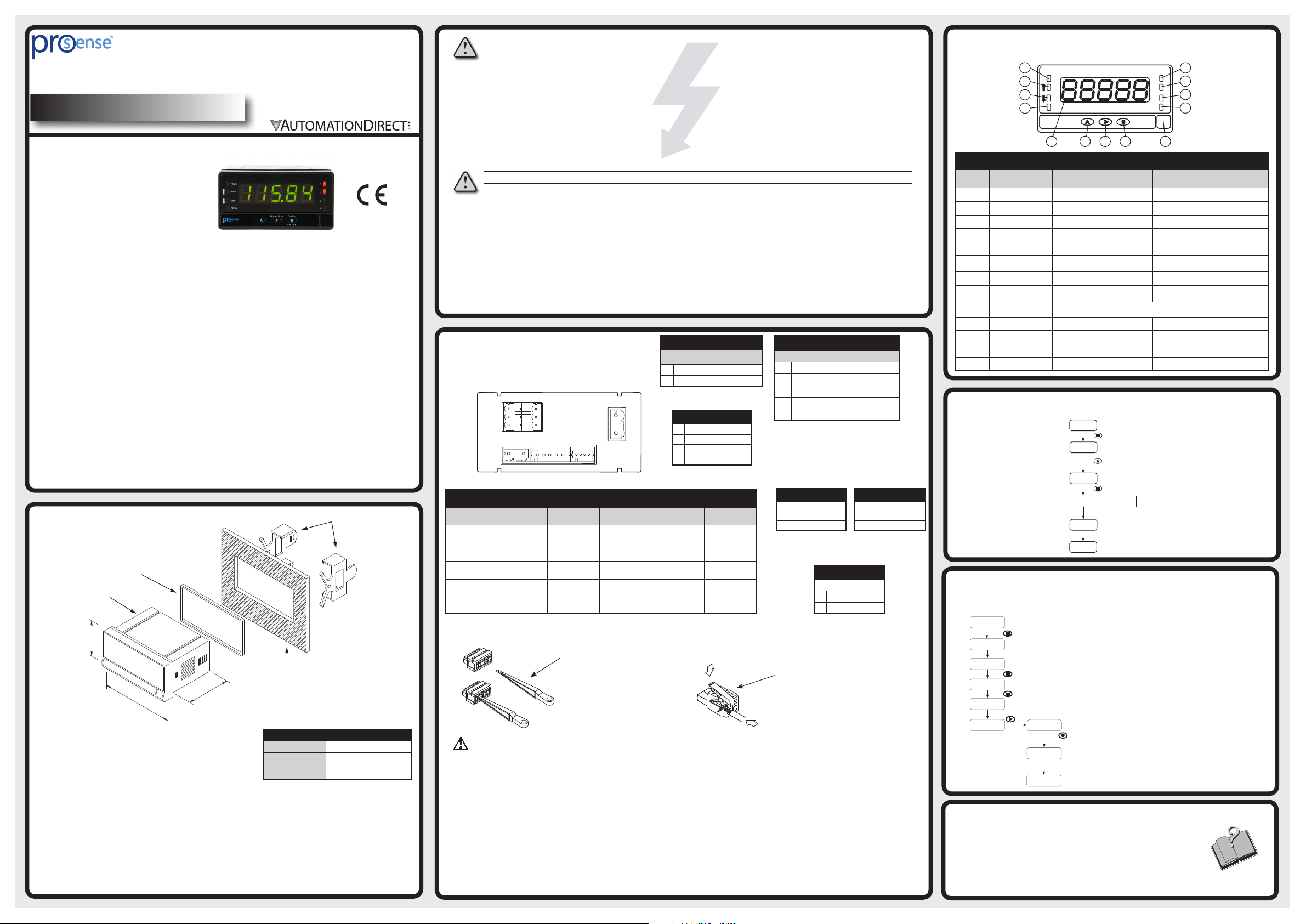
Dimensions and Mounting
Sealing gasket
DPM3 Meter
48mm
60mm
96mm
To install the instrument, prepare a 92mm x 45mm panel
cut-out and slide the unit inwards making sure to place the
sealing gasket between the front side panel and the front
bezel.
While holding the unit in place, put the fixing clips on both
sides of the case and slide them through the guide tracks
until they reach the panel at the rear side.
Press slightly to fasten the clips to the latching slots on the
case and get the unit fully assembled and close fitted to
achieve a good seal.
To remove the instrument from the panel, pull the rear
fixing clips latching tabs outwards until they are disengaged,
then slide the fixing clips back over the case.
• Optional (2) Form C SPDT
Activation on increasing or decreasing input
signal
Hysteresis or time delay operation
Display color change on relay operation
• Configuration for direct or reverse acting
• Total or selective configuration lock out
• Programmable functions include:
Minimum (valley) and maximum (peak) value
memory
Minimum (valley) and maximum (peak) value
reset
Hold
• Filtering to minimize display bounce
• Display brightness adjustment
(2) Fixing clips
Panel mounting surface
Installation
Dimensions
Panel Cutout
Case Material
96 x 48 x 60mm (1/8 DIN)
92 x 45mm
(Max. panel thickness 10mm)
Polycarbonate UL 94 V-0
WARNING: To minimize the risk of potential safety problems, you should follow all applicable local and national
codes that regulate the installation and operation of your equipment. These codes vary from area to area and it is
your responsibility to determine which codes should be followed, and to verify that the equipment, installation,
and operation are in compliance with the latest revision of these codes.
Equipment damage or serious injury to personnel can result from the failure to follow all applicable codes and
standards. We do not guarantee the products described in this publication are suitable for your particular application, nor do we assume any responsibility for your product design, installation, or operation.
If you have any questions concerning the installation or operation of this equipment, or if you need additional
information, please call us at 1-800-633-0405 or 770-844-4200.
This publication is based on information that was available at the time it was printed. At Automationdirect.com®
we constantly strive to improve our products and services, so we reserve the right to make changes to the products
and/or publications at any time without notice and without obligation. This publication may also discuss features
that may not be available in certain revisions of the product.
WARNING! Electric shock danger
1. Keep away from high-voltage and high-frequency environment during the installation to prevent interference.
Avoid using the device in environments which contain: (a) dust or corrosive gas; (b) high humidity or high
radiation; (c) shock or vibration
2. Make sure the input power is switched off when installing or uninstalling the DPM3 to prevent harm to
personnel or equipment.
3. Before switching on the input power, check the signal connection, e.g. the input voltage and polarity. Voltage
that is too high may cause damage to the DPM3.
4. Front cover should be cleaned only with a soft cloth soaked in neutral soap product. DO NOT USE
SOLVENTS.
5. Outputs remain active in Programming Mode.
Wiring Terminals
Note: For additional wiring information download
complete manual from www.AutomationDirect.com
CN5
CN4
1 2
1
4
2
5
6
3
CN1 CN2 CN3
1 2 3 4 5
1 2 3 4
CN6
CN1
AC Supply DC Supply
1 Line 1 VDC
2 Neutral 2 VDC
Polarity insensitive for
DC power
1
2
CN3
1 Common
2 Peak
3 Valley
4 Hold
1 Common
2 Shunt / 2V
3 200mA
4 1A / 5A
5 20 / 200 / 600V
CN2
Electrical Inputs
2 SPDT Relays (-A2R)
Terminals
Connector CN1 CN2 CN3 CN4 & CN5 CN6
Wire cross
section
Strip length 8 to 9mm 5 to 6mm 5 to 6mm 8 to 9mm 8 to 9mm
Manufacturer
Cage clamp
connection
CN2 and CN3 Terminals
0.08 to 2.5mm²
(28 to 12 AWG)
Wago 231202/026-000
Insertion tool or
screwdriver with
0.5 mm x 3.0 mm
blade
0.08 to 1.5mm²
(28 to 14 AWG)
Wago 734-105 Wago 733-104
Insertion tool or
screwdriver with
0.3 mm x 1.8 mm
blade
Insertion Tool (included with meter)
Insert wires into the proper terminal
while using the insertion tool to open
the clip inside the connector. Release
the insertion tool to fix wire to the
terminal.
0.08 to 0.5mm²
(28 to 20 AWG)
Insertion tool or
screwdriver with
0.3 mm x 1.8 mm
blade
0.08 to 2.5mm²
(28 to 12 AWG)
Wago 231303/026-000
Insertion tool or
screwdriver with
0.5 mm x 3.0 mm
blade
0.08 to 2.5mm²
(28 to 12 AWG)
Wago 231302/026-000
Insertion tool or
screwdriver with
0.5 mm x 3.0 mm
blade
CN1, CN4, CN5 and
CN6 Terminals
CN4 (Relay 2)
4 NO2
5 CM2
6 NC2
NO: Normally Open, CM: Common,
NC: Normally Closed
Analog Output
1 (-) 4-20mA
2 (+) 4-20mA
Insertion Tool (included with meter)
Insert wires into the proper terminal
while using the insertion tool to open
the clip inside the connector. Release
the insertion tool to fix wire to the
terminal.
CN5 (Relay 1)
1 NO1
2 CM1
3 NC1
CN6
Warning: If this instrument is not installed and used in accordance with these instructions, the protection provided by it
against hazards may be impared. To meet the requirements of EN 610101-1 standard, where the unit is permanently
connected to main supply, it is obligatory to install a circuit breaking device that is easily reachable by the operator and
clearly marked as the disconnecting device.
To guarantee electromagnetic compatibility, the following guidelines should followed:
• Power supply wires should be separately routed from
signal wires and never ran in the same conduit.
• Use shielded cable for signal wiring.
• Cable cross-section must be ≥0.25mm²
Before connecting signal wires, signal type and input range should be verified to be within the proper limits. Do not
connect more than one input signal to the meter simultaneously.
Programming Panel Keys
1
TRMS
MAX
MIN
PROG
4
MICRA
5
MAX/MIN
DATA
ENTER
8
7
Programming Panel
Description Run Mode Programming Mode
#
1 True RMS Indicates reading AC using true RMS ---
2 MAX Indicates peak displayed ---
3 MIN Indicates valley displayed ---
4 PROG --- Indicates programming mode
5 DISPLAY Displays the input variable Displays programming parameters
6 UP Direct access to setpoints Increments the value of the flashing digit
7 SHIFT/MAX/MIN KEY Recalls Max/Min values Moves to the right
8 ENTER KEY Enters in PROG mode. Displays data Accepts data. Advances program
Free space for units
9
label
10 LED Output 4 --- ---
11 LED Output 3 --- ---
12 LED Output 2 Activaton Output 2 Programming output 2
13 LED Output 1 Activation Output 1 Programming output 1
13
1
12
2
11
3
4
10
9
---
Return to Factory Configuration
Run mode
Programming mode
If parameter lock has been enabled,
dAtA will be displayed instead of Pro.
>3sec
Enter code 74
Save values
Run mode
Total Configuration Lock-out
Note: For selective lock-out configuration download complete manual from
www.AutomationDirect.com
Run Mode
>3s
Enter code (default code is 0000). If code is forgotten, perform
Return to Factory Configuration to again have access to parameters
lock out configuration.
Select LISt and totLC will momentarily display
Select 1 for complete lock out of all parameters.
When locked out, parameter values can be viewed but
not changed.
Save values
Run Mode
Additional Help and Support
• For additional information on this product download the complete manual
from www.AutomationDirect.com
• For additional technical support and questions, call our Technical Support
team @ 1-800-633-0405 or 770-844-4200
Page 2
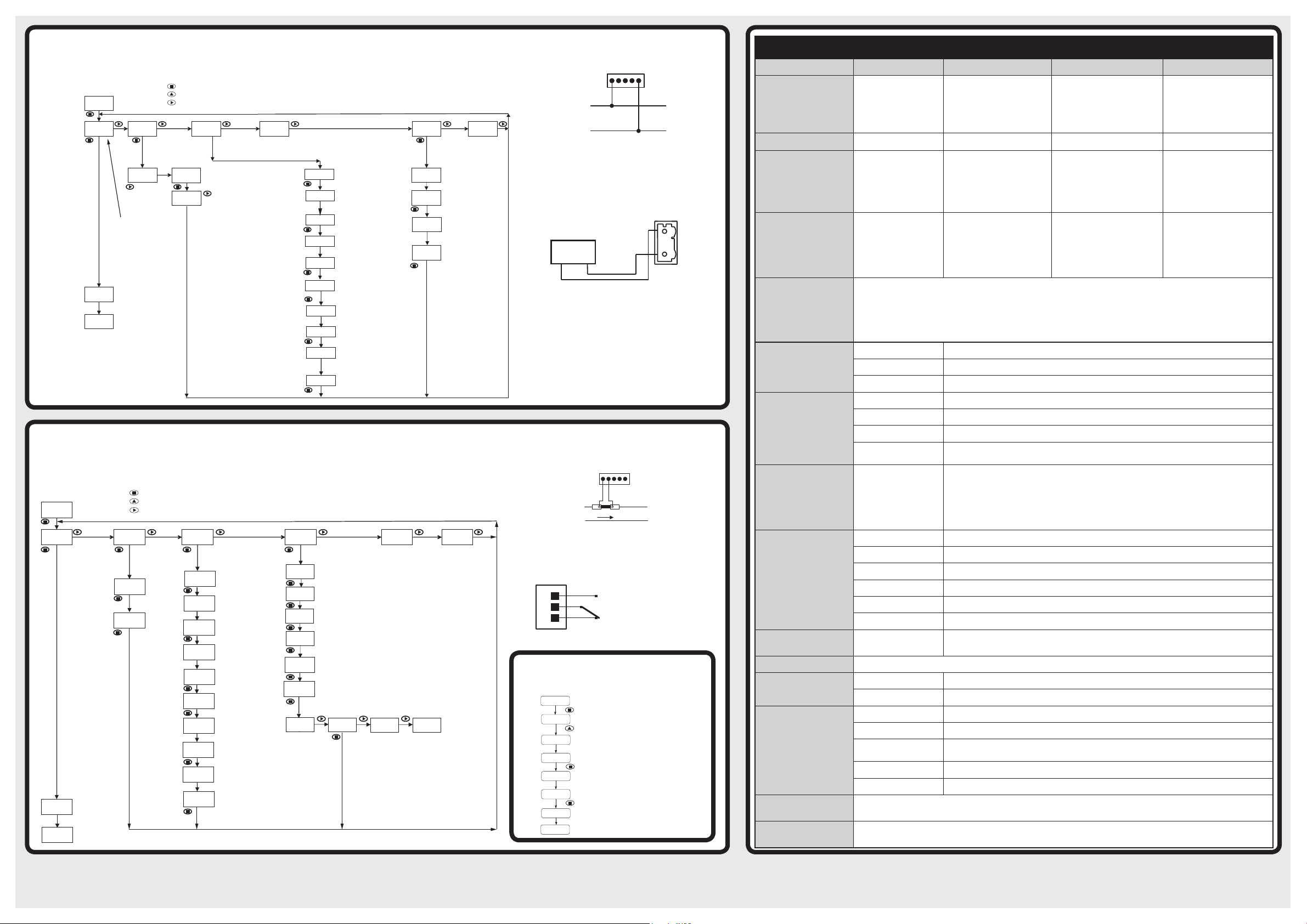
Model DPM3-E-A2R-H Example Application:
-
Pro
-
StorE
U-AC
outHI
±1
88.88
outLo
±1
88.88
600U
-
Pro-CnInP
StorE
CndSP
SEtP
Anout
LoGIn
±1
8888
dSP 2
-
on
-
±1
88.88
R
ed
Green
Am
ber
TERMINALS CN2
DC/ AC
TERMINALS
50/ 60/ 100mV
0-200 VAC input display range of 0-200 with a 4-20mA output scaled to match.
Note: For additional configuration information download the complete manual from www.AutomationDirect.com
ENTER: Vertical displacement.
8888
Pro: Programming Mode.
If total parameter lock
out has been enabled,
dAtA will be displayed
instead of Pro.
Run Mode
8888
Run Mode
CnInP
U-dC
UP: Changes active digit.
SHIFT: Horizontal displacement.
CndSP
Input
Display
Menu
Menu
Volts AC
Select
600V Input
SEtP
Relay
Configuration
Menu
InP1 value entered
manually using
programming keys
Scale
SCAL
Input signal value
corresponding to
InP 1
desired display value
dSP1
Enter 0 for
±18.888
this example
Display value
dSP 1
corresponding to InP1
Enter 0 for
±18888
this example
Select desired decimal
±188.88
point location. xxxx.x
for this example
Input signal value
InP 2
corresponding to desired
display value of dSP2
Enter 200 for this
±18.888
example
Display value
dSP 2
corresponding to InP2
Select desired decimal
±188.88
point location. xxx.xx
for this example
Anout
Analog
Output
Menu
LoGIn
Logic
Functions
Menu
Enter display value
corresponding to 20mA
output. Enter 200.0 for
this example.
Enter display value
corresponding to 4mA
output. Enter 0.0 for
this example.
Model DPM3-E-A2R-H Example Application:
0-250A DC input via a 250A/100mV DC shunt, 0.0 to 250.0 display, relay 1 set for N.O. operation activates on an increase
to a display value of 200.0 after a 5 sec. delay. Display turns red when relay activates.
Note: For additional configuration information download the complete manual from www.AutomationDirect.com
ENTER: Vertical displacement.
8888
Run Mode
Pro: Programming
Mode. If total parameter
lock out has been
enabled, dAtA
will be displayed
instead of Pro.
Save values
8888
Run Mode
UP: Changes active digit.
SHIFT: Horizontal displacement.
Input
Menu
DC
A-dC
Amperage
Input
Select
100nU
100mV
input
Display
Menu
InP1 and InP2 values
entered manually using
SCAL
programming keys
Input signal value
InP 1
corresponding to
desired display value
dSP1
±8
8.888
Enter 0 for this example
Display value
dSP 1
corresponding to InP1
Enter 0 for this example
Select desired decimal
point location. xxxx.x
±18.888
for this example
Input signal value
InP 2
corresponding to desired
display value dSP2
Enter 100.0 for this
±88888
example
Display value
corresponding
to InP2
±18888
Enter 250.00 for this example
Relay
Configuration
Menu
SEt 1
Relay 1 setpoint
Enable Relay 1 operation
Enter setpoint 200.00 for this example
Relay 1 activates on an increasing display value
-Hito setpoint.
dLy: Relay 1 changes state at SEt 1 setpoint
-dLyafter time delay
Enter delay time of 5 seconds for this
88
example.
no CH
ALArM
ALArM
Analog
Output
Menu
ALArM
Logic
Functions
Menu
Display turns
red in color
when Relay 1
activates for this
example.
Input Wiring:
12345
N
V
L
Voltmeter 20/ 200/ 600 V
Analog Output Wiring:
TERMINALS CN6
1
4-20mA Load,
PLC, Input, Etc
+
-
+4-20mA
2
-4-20mA
Input Wiring
12345
N
L
SHUNT
I
Ammeter with
Shunt
Relay output wiring
1
2
3
CM
NO
NC
RELAY 1
Terminals CN5
Direct Access to Relay Setpoints
(-A2R models only)
Run Mode
Programming Mode
.
Enter setpoint value for relay 1
.
Enter setpoint value for relay 2
Save values
Run Mode
Technical Specifications
Input DC Voltage AC Voltage DC Current AC Current
Range....Input Impedance
Input Frequency Range
Resolution
Accuracy
Accuracy Conditions
Conversion
Display
Relays
-A2R Only
Analog Output
-A2R Only
Power Supply and Fuses
Power Consumption
Filter
Environmental Conditions
Environmental Air
Agency Approvals
2V....100kΩ
20V....1MΩ
200V....1MΩ
600V....1MΩ
2V....75kΩ
20V....850kΩ
200V....850kΩ
600V....850kΩ
1A....0.014 Ω
5A....0.014 Ω
50mV.... 1.8 MΩ
60mV....1.8 MΩ
100mV....1.8 MΩ
– 40Hz to 10kHz True RMS Measurement – 40Hz to 10kHz True RMS Measurement
200mA....0.01 mA
200mA....0.75 Ω
2V....0.1 mV
±20V....1mV
±200V....10mV
±600V....0.1 V
2V....0.1 mV
20V....1mV
200V....10mV
600V....0.1 mV
1A....1mA
5A....1mA
50mV....0.01 mV
60mV....0.01 mV
100mV....0.01 mV
200mA.... 0.1 % rdg ± 0.05 mA
2V.... 0.05% rdg ± 0.3 mV
±20V....0.05% rdg ± 3mV
±200V....0.05% rdg ± 30mV
±600V....0.05% rdg ± 0.3 V
2V.... 0.3% rdg ± 0.3 mV
20V....0.3% rdg ± 3mV
200V....0.3% rdg ± 30mV
600V....0.3% rdg ± 0.3 V
1A....0.1 % rdg ± 5mA
5A....0.1 % rdg ± 5mA
50mV.... 0.1 % rdg ± 0.1 mV
60mV....0.1 % rdg ± 0.1 mV
100mV....0.1 % rdg ± 0.1 mV
AC or DC Input:
15 minutes warmup
25°C ± 5°C ambient temperature
100 ppm/°C temperature coefficient
10-75% RH non-condensing
Crest Factor: 3, Accuracy +/-(0.2% + 10 digits); 5, Accuracy +/-(1% + 20 digits)
40 Hz to 10 kHz Accuracy +/-(1% + 20 digits)
AC Input:
3% to 100% of input range
45 Hz to 400 Hz sine wave
Technique Sigma-Delta
Resolution ±15 bits
Conversion rate 20 times per second
Range -19999 / +19999, 5 LED digits 14mm (Programmable color Red, Green, Amber)
LEDs 8, functions and outputs status
Display refresh rate 20 times per second
Display / Input overrange
indication
"-oUEr” , “oUEr”
Nominal contact rating....................8A at 250VAC / 24VDC
Maximum switching current (resistive load)....................8A
(2) Relays, Form C SPDT
Maximum switching power.........................2000VA / 192W
Maximum switching voltage...................400VAC / 125VDC
Contact resistance...........................≤100mΩ at 6VDC at 1A
Operate time.................................................................≤10ms
Type 4-20 mA Sourcing
Maximum load ≤500Ω
Resolution 13 bits
Accuracy 0.1%FS ±1 bit
Response time 10ms
Thermal drift 0.5µA / ºC
-H High Voltage:
-L Low Voltage:
85-265 VAC 50/60 Hz (100-300 VDC), (recommended fusing 0.5A/250V, DIN 41661)
22-53 VAC 50/60 Hz (10.5 - 70 VDC), (recommended fusing 2A/250V, DIN 41661)
5W without options, 8W max.
Cutoff frequency 4Hz to 0.05Hz
Slope 20dB/Dec.
Operating temperature -10ºC to +60ºC (14ºF to 140ºF)
Storage temperature -25ºC to +85ºC (-13ºF to 185ºF)
Relative humidity
(non-condensing)
<95% @ 40ºC (104ºF)
Maximum altitude 2000m
Frontal protection degree IP65
No corrosive gases permitted
CE
200mA.... 0.75 Ω
1A....0.014 Ω
5A....0.014 Ω
50mV.... 1.5 MΩ
60mV....1.5 MΩ
100mV....1.5 MΩ
200mA....0.01 mA
1A....1mA
5A....1mA
50mV....0.01 mV
60mV....0.01 mV
100mV....0.01 mV
200mA.... 0.3 % rdg ± 0.05 mA
1A....0.3 % rdg ± 5mA
5A....0.3 % rdg ± 5mA
50mV.... 0.3 % rdg ± 0.1 mV
60mV....0.3 % rdg ± 0.1 mV
100mV....0.3 % rdg ± 0.1 mV
Copyright 2019, Automationdirect.com Incorporated/All Rights Reserved Worldwide
Quick Start Guide: DPM3-E-H, DPM3-E-2R-H, DPM3-E-L, DPM3-E-2R-L
 Loading...