

Page 1
Digital Panel Meter
CN4
(1
DPM1-P Series
Quick Start Guide
3505 HUTCHINSON ROAD
Models:
DPM1-P-A2R-H
DPM1-P-A2R-L
This Quick Start Guide provides basic information for configuring the ProSense DPM1-P series digital
panel meters. For more specific information and advanced configuration instructions please visit
www.AutomationDirect.com and download the free instruction manual for the DPM1-P series.
Features
• 48 x 24mm 1/32 DIN
• 4 digit (0 to 9999) red LED display
• Selectable decimal point
• Frequency/Tachometer/Rate/PWM Modes
- AC voltage
- Magnetic sensor
- NAMUR sensor
- NPN/PNP sensor
- TTL/24V encoder
- Switched contact
• AC or DC powered
• Sensor excitation voltage
• (2) Form A SPST normally open relays
Activation on increasing or decreasing input
signal
Hysteresis or time delay operation
• 0/4-20mA analog output
• Total or selective configuration lock out
• Minimum and maximum value memory
• Display brightness adjustment
Dimensions and Mounting
Sealing gasket
DPM1 Meter
24mm
Panel mounting surface
100mm
48mm
To install the instrument, prepare a 45mm x 22mm panel
cut-out and slide the unit inwards making sure to place the
sealing gasket between the front side panel and the front
bezel.
While holding the unit in place, put the fixing clip around
Dimensions
Panel Cutout
Case Material
CUMMING, GA 30040-5860
Fixing clip
Installation
48 x 24 x 100mm (1/32 DIN)
45 x 22mm
(Max. panel thickness 7mm)
Polycarbonate UL 94 V-0
WARNING: To minimize the risk of potential safety problems, you should follow all applicable local
and national codes that regulate the installation and operation of your equipment. These codes vary
from area to area and it is your responsibility to determine which codes should be followed, and to
verify that the equipment, installation, and operation are in compliance with the latest revision of
these codes.
Equipment damage or serious injury to personnel can result from the failure to follow all applicable
codes and standards. We do not guarantee the products described in this publication are suitable for
your particular application, nor do we assume any responsibility for your product design, installation,
or operation.
If you have any questions concerning the installation or operation of this equipment, or if you need
additional information, please call us at 1-800-633-0405 or 770-844-4200.
This publication is based on information that was available at the time it was printed. At
Automationdirect.com® we constantly strive to improve our products and services, so we reserve the
right to make changes to the products and/or publications at any time without notice and without
obligation. This publication may also discuss features that may not be available in certain revisions of
the product.
WARNING! Electric shock danger
1. Keep away from high-voltage and high-frequency environment during the installation to prevent interference.
Avoid using the device in environments which contain: (a) dust or corrosive gas; (b) high humidity or high
radiation; (c) shock or vibration
2. Make sure the input power is switched off when installing or uninstalling the DPM1 to prevent harm to
personnel or equipment.
3. Before switching on the input power, check the signal connection, e.g. the input voltage and polarity. Voltage
that is too high may cause damage to the DPM1.
4. Front cover should be cleaned only with a soft cloth soaked in neutral soap product. DO NOT USE
SOLVENTS.
5. Outputs remain active in Programming Mode.
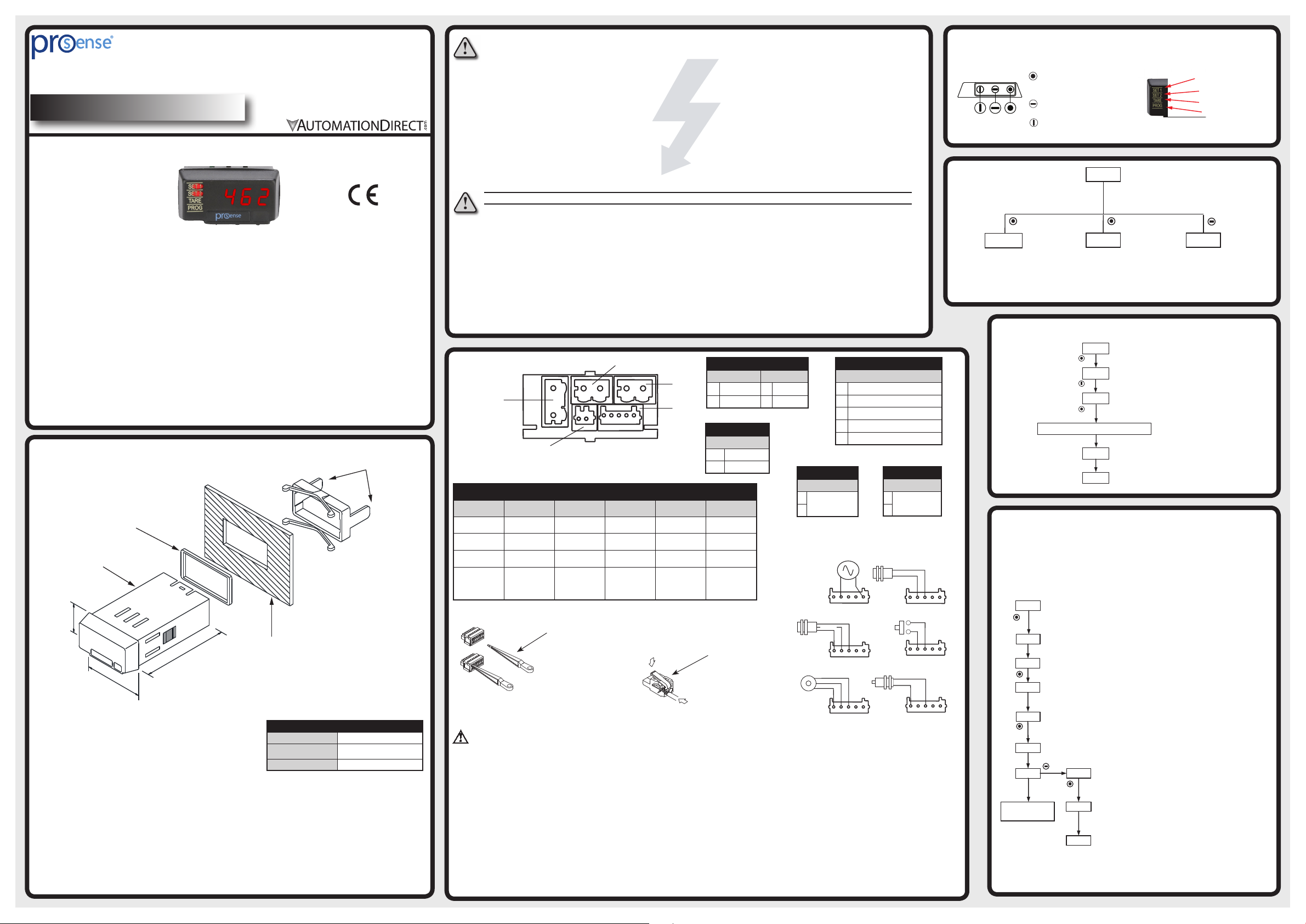
Wiring
Terminals
CN1
1
2
11122 2
125 34
CN5
CN2
CN3
Note: For additional wiring information download complete
manual from www.AutomationDirect.com
Terminals
Connector CN1 CN2 CN3 CN4 CN5
Wire cross section
Strip length 8 to 9mm 5 to 6mm 5 to 6mm 8 to 9mm 8 to 9mm
Manufacturer
Cage clamp
connection
0.08 to 2.5mm²
(28 to 12 AWG)
Wago 231202/026-000
Insertion tool or
screwdriver with
0.5 mm x 3.0 mm
blade
CN2 and CN3 Terminals
0.08 to 0.5mm²
(28 to 20 AWG)
Wago 733-105 Wago 733-102
Insertion tool or
screwdriver with
0.3 mm x 1.8 mm
blade
Insertion Tool (included with meter)
Insert wires into the
proper terminal while
using the insertion tool
to open the clip inside
the connector. Release
the insertion tool to fix
wire to the terminal.
0.08 to 0.5mm²
(28 to 20 AWG)
Insertion tool or
screwdriver with
0.3 mm x 1.8 mm
blade
0.08 to 2.5mm²
(28 to 12 AWG)
Wago 231102/026-000
Insertion tool or
screwdriver with
0.5 mm x 3.0 mm
blade
CN1, CN4 and CN5
Terminals
AC Supply DC Supply
1 Line 1 -VDC
2 Neutral 2 +VDC
Analog Output
1 -0/4-20mA
2 +0/4-20mA
0.08 to 2.5mm²
(28 to 12 AWG)
Wago 231302/026-000
Insertion tool or
screwdriver with
0.5 mm x 3.0 mm
blade
Insertion Tool (included with meter)
Insert wires into the
proper terminal while
using the insertion tool
to open the clip inside
the connector. Release
the insertion tool to fix
wire to the terminal.
CN3
CN1
CN2
Signal Input
1 10 - 600 VAC
2 Not used
3 + Input pulses
4 Common
5 + Excitation (5, 8, 12V) @ 60mA
CN4
Relay 2
1
2
1
2
Relay 1
N.O. Contact
Input Wiring Diagrams
10-600V AC Input
CN2
5 4 3 2 1
NPN / PNP / PWM sensors
+ Pulses (Out)
Common
+ Exc.
CN2
5 4 3 2 1
TTL/24V DC Encoder input
+ Pulses (Out)
Common
+ Exc.
CN2
5 4 3 2 1
CN2
CN2
+ Pulses (Out)
+ Exc.
CN2
CN5
N.O. Contact
Magnetic sensor
5 4 3 2 1
Switched contact
5 4 3 2 1
NAMUR sensor
5 4 3 2 1
Warning: If this instrument is not installed and used in accordance with these instructions, the protection
provided by it against hazards may be impaired. To meet the requirements of EN 610101-1 standard, where the
unit is permanently connected to main supply, it is obligatory to install a circuit breaking device that is easily
reachable by the operator and clearly marked as the disconnecting device.
Programming Keys
(Bottom View)
ENTER: Enters configuration
and validates data and
parameters.
(Bottom View)
SHIFT: Selects mode or shifts
blinking digit in configuration.
UP: Increases value of blinking
digit in configuration mode.
Main Menu
<3s >3s
Pro
Enters configuration
menu (non-locked
out parameters)
) If all parameters are locked out, display shows dAtA.
1
.
Return to Factory Configuration
<3s ec
>3s ec
Total Configuration Lock-out
Note: For selective lock-out configuration download complete manual
from www.AutomationDirect.com
Run Mode
8888
>3sec
CodE
Enter code (default code is 0000). If code is forgotten,
8888
CHAn
perform Return to Factory Configuration to again
have access to parameters lock-out configuration.
Previous Settings will be lost.
Change code? No for this example.
no
Select YES for complete lock out of ALL parameters. When locked
out parameter values can be viewed but not changed (dAtA Mode
ALL
instead of Pro Programming Mode)
YES no
8888
Enters lock
out menu.
Indicators
Relay 1 activation
Run Mode
Displays value according to all configured
parameters.
Run Mode
Programming Mode
If parameter lock out has been enabled, dAtA
will be displayed instread of Pro
Enter code 74
Save value
Run Mode
Displays detected maximum and minimum
values. Value RESET can be done by
pressing at least 3s (then new maximum or
Relay 2 activation
Not used
Programming
mode
Hi-Lo CodE
minimum value is displayed).
<3s
the case and slide it until it reaches the panel at the rear side.
Press slightly to fasten the clips to the latching slots on the
case and get the unit fully assembled and close fitted to
achieve a good seal.
To remove the instrument from the panel, pull the rear
fixing clips latching tabs outwards until they are disengaged,
then slide the fixing clips back over the case.
To guarantee electromagnetic compatibility, the following guidelines should be followed:
• Power supply wires should be separately routed from
signal wires and never ran in the same conduit.
• Use shielded cable for signal wiring.
• Cable cross-section must be ≥0.25mm²
Before connecting signal wires, signal type and input range should be verified to be within the proper limits. Do not
Refer to manual
for options
Stor
8888
Save values
Run Mode
connect more than one input signal to the meter simultaneously.
Page 2

Model DPM1-P-A2R-H Example Application :
10-600VAC input, 0.0 to 100.0 Hz display, relay 1 set to activate on a decrease to a display value of 20.0 after a 5 sec. delay, relay 2 set to activate on a increase
to a display value of 80.0 after a 5 sec. delay, analog output of 4-20mA over a display range of 0.0 to 100.0.
Note: For additional configuration information download complete manual from www.AutomationDirect.com
Run Mode
8888
< 3 sec.
Stor
8888
Pro
InP
1
Save values
Run Mode
Pro: Programming Mode. If total parameter lock out has been
enabled, dAtA will be displayed instead of Pro.
ModE
Select 1 for
10-600 VAC
input
FrEC
dCP
Frequency value
Decimal place
1 0.1 0.01
Select 0.1 for
this example
SEt
Relay Configuration Menu
Refer to “Relay Setpoints”
menu to enter or change relay
setpoints.
Relay 1 configuration
CnF
Relay 1 changes state at
dLy
SP1.U setpoint after time
delay
Enter delay time of
88
5 seconds for this example
Lo
Hi
Relay 1 activates on a decreasing
display to setpoint. Select Lo for
this example.
CnF
Relay 2 configuration
Relay 2 changes state at SP2.U
dLy
setpoint after time delay
Enter delay time of
88
5 seconds for this example
Relay 2 activates on an
increasing display to setpoint.
Select Hi for this example.
A.out
tyPE
0-20
Analog output menu
Analog out signal
selection
4-20
Lo
8888
Hi
8888
Select 4-20 for
this example
Enter display
value of 0.0 for
4mA output for
this example
Enter display
value of 100.0
for 20mA
output for this
example
10-600 VAC Input Wiring
Relay Setpoints
Run Mode
<3 sec.
Programming Mode
.
Relay 1 setpoint
Enter setpoint of 20.0 for
this example
Relay 2 setpoint
.
Enter setpoint of 80.0 for
this example
Save values
Run Mode
Relay Output wiring
1
2
1
2
RELAY 1
Terminals CN4
SPST- Normally Open
RELAY 2
Terminals CN5
SPST- Normally Open
Note: For additional wiring information download complete manual from www.AutomationDirect.com
CN2
5 4 3 2 1
Technical Specifications
12kHz (tachometer rpm or rate modes)
85-265VAC 50/60Hz or 100-300VDC
21-53VAC 50/60Hz or 10.5-70VDC
Signal Input
AC Voltage Input
Magnetic Sensor Input
NAMUR Sensor Input
NPN/PNP/PWM Sensors Input
TTL/24V Encoder Input
Switched Contact Input
Accuracy at 23ºC ±5ºC
Power Supply and Fuses
Power Consumption
Stabilized Excitations
Display
Relays
Analog Output (0/4-20mA)
Environmental Conditions
Environmental Air
Agency Approvals
Maximum Frequency
Minimum Frequency (all modes) 0.01Hz
Range 10 to 600 VAC
Sensitivity
R
C
I
ON
I
OFF
R
C
Logic level “0” < 2.4 VDC
Logic level “1” > 2.6 VDC
Logic level “0” < 2.4 VDC
Logic level “1” > 2.6 VDC
V
C
R
C
F
C
Maximum error ± (0.01% of reading +1digit)
Temperature coefficient 50ppm / ºC
Warm-up time 5 minutes
DPM1-P-A2R-H
DPM1-P-A2R-L
5V@60mA ; 8V@60mA and 12V@60mA (Menu selectable)
Range 0 to 9999
Type 4-digit 8mm (0.31”), red
Decimal point Configurable
LEDs 4, for functions and outputs
Display refresh rate 4 times per second
Input overrange indication “OuE” or “0” flashing
Display overrange indication “OuE”
Relays, maximum and minimum value refresh 10 times per second
2 Relays (Form A) SPST normally open 5A @ 250VAC / 30VDC
Resolution 5.5µA
Accuracy ±(0.3% of reading +40µA)
EMI Max. influence ±0.25mA
Temperature coefficient 3µA/ºC
Maximum load ≤500Ω
Operating temperature -10ºC to +60ºC (14ºF to 140ºF)
Storage temperature -25ºC to +85ºC (-13ºF to 185ºF)
Relative humidity (non-condensing) <95% @ 40ºC (104ºF)
Maximum altitude 2000m
Frontal protection degree IP65
(Recommended fusing, 0.2A/250V, 5mm x 20mm glass miniature or DIN
(Recommended fusing, 1A/250V, 5mm x 20mm glass miniature or DIN
5W
No corrosive gases permitted
CE
Additional Help and Support
• For additional information on this product download the complete manual from www.
AutomationDirect.com
• For additional technical support and questions, call our Technical Support team @
1-800-633-0405 or 770-844-4200
• Scan or click the QR link for configuration and programming videos for the ProSense
DPM Series Panel Meters
9999Hz (frequency mode)
100Hz (duty/PWM mode)
Vin min. ≥ 30mV for f ≤ 60Hz
Vin min. > 300mV for f ≥ 6kHz
1.5kΩ
< 1mA DC
> 3mA DC
3.9kΩ (NPN) ; 1.5kΩ (PNP)
5V (internal)
3.9kΩ
20Hz
(Ton, Toff > 25ms)
41661 equivalent)
41661 equivalent)
Copyright 2020, Automationdirect.com Incorporated/All Rights Reserved Worldwide
Quick Start Guide: DPM1-P-A2R-H, DPM1-P-A2R-L
 Loading...