

Page 1

D0–DCM Data
Communications
Module
Manual Number D0–DCM–M
Page 2

WARNING
Thank you for purchasing automation equipment from Automationdirect.com™, doing business as,
AutomationDirect. We want your new DirectLOGIC™ automation equipment to operate safely. Anyone who installs
or uses this equipment should read this publication (and any other relevant publications) before installing or operating
the equipment.
To minimize the risk of potential safety problems, you should follow all applicable local and national codes that regulate
the installation and operation of your equipment. These codes vary from area to area and usually change with time. It is
your responsibility to determine which codes should be followed, and to verify that the equipment, installation, and
operation are in compliance with the latest revision of these codes.
At a minimum, you should follow all applicable sections of the National Fire Code, National Electrical Code, and the
codes of the National Electrical Manufacturer’s Association (NEMA). There may be local regulatory or government
offices that can also help determine which codes and standards are necessary for safe installation and operation.
Equipment damage or serious injury to personnel can result from the failure to follow all applicable codes and
standards. We do not guarantee the products described in this publication are suitable for your particular application,
nor do we assume any responsibility for your product design, installation, or operation.
Our products are not fault–tolerant and are not designed, manufactured or intended for use or resale as on–line control
equipment in hazardous environments requiring fail–safe performance, such as in the operation of nuclear facilities,
aircraft navigation or communication systems, air traffic control, direct life support machines, or weapons systems, in
which the failure of the product could lead directly to death, personal injury, or severe physical or environmental
damage (”High Risk Activities”). AutomationDirect specifically disclaims any expressed or implied warranty of fitness
for High Risk Activities.
For additional warranty and safety information, see the Terms and Conditions section of our Desk Reference. If you
have any questions concerning the installation or operation of this equipment, or if you need additional information,
please call us at 770–844–4200.
This publication is based on information that was available at the time it was printed. At AutomationDirect we
constantly strive to improve our products and services, so we reserve the right to make changes to the products and/or
publications at any time without notice and without any obligation. This publication may also discuss features that may
not be available in certain revisions of the product.
Trademarks
This publication may contain references to products produced and/or offered by other companies. The product and
company names may be trademarked and are the sole property of their respective owners. AutomationDirect
disclaims any proprietary interest in the marks and names of others.
Copyright 2005, Automationdirect.com™ Incorporated
All Rights Reserved
No part of this manual shall be copied, reproduced, or transmitted in any way without the prior, written consent of
Automationdirect.com™ Incorporated. AutomationDirect retains the exclusive rights to all information included in
this document.
Page 3

AVERTISSEMENT
Nous vous remercions d’avoir acheté l’équipement d’automatisation de Automationdirect.comE, en faisant des affaires
comme, AutomationDirect. Nous tenons à ce que votre nouvel équipement d’automatisation DirectLOGIC™ fonctionne
en toute sécurité. Toute personne qui installe ou utilise cet équipement doit lire la présente publication (et toutes les autres
publications pertinentes) avant de l’installer ou de l’utiliser.
Afin de réduire au minimum le risque d’éventuels problèmes de sécurité, vous devez respecter tous les codes locaux et
nationaux applicables régissant l’installation et le fonctionnement de votre équipement. Ces codes diffèrent d’une région à
l’autre et, habituellement, évoluent au fil du temps. Il vous incombe de déterminer les codes à respecter et de vous assurer
que l’équipement, l’installation et le fonctionnement sont conformes aux exigences de la version la plus récente de ces
codes.
Vous devez, à tout le moins, respecter toutes les sections applicables du Code national de prévention des incendies, du
Code national de l’électricité et des codes de la National Electrical Manufacturer’s Association (NEMA). Des organismes de
réglementation ou des services gouvernementaux locaux peuvent également vous aider à déterminer les codes ainsi que
les normes à respecter pour assurer une installation et un fonctionnement sûrs.
L’omission de respecter la totalité des codes et des normes applicables peut entraîner des dommages à l’équipement ou
causer de graves blessures au personnel. Nous ne garantissons pas que les produits décrits dans cette publication
conviennent à votre application particulière et nous n’assumons aucune responsabilité à l’égard de la conception, de
l’installation ou du fonctionnement de votre produit.
Nos produits ne sont pas insensibles aux défaillances et ne sont ni conçus ni fabriqués pour l’utilisation ou la revente en tant
qu’équipement de commande en ligne dans des environnements dangereux nécessitant une sécurité absolue, par
exemple, l’exploitation d’installations nucléaires, les systèmes de navigation aérienne ou de communication, le contrôle de
la circulation aérienne, les équipements de survie ou les systèmes d’armes, pour lesquels la défaillance du produit peut
provoquer la mort, des blessures corporelles ou de graves dommages matériels ou environnementaux (”activités à risque
élevé”). La société AutomationDirect nie toute garantie expresse ou implicite d’aptitude à l’emploi en ce qui a trait aux
activités à risque élevé.
Pour des renseignements additionnels touchant la garantie et la sécurité, veuillez consulter la section Modalités et
conditions de notre documentation. Si vous avez des questions au sujet de l’installation ou du fonctionnement de cet
équipement, ou encore si vous avez besoin de renseignements supplémentaires, n’hésitez pas à nous téléphoner au
770–844–4200.
Cette publication s’appuie sur l’information qui était disponible au moment de l’impression. À la société AutomationDirect,
nous nous efforçons constamment d’améliorer nos produits et services. C’est pourquoi nous nous réservons le droit
d’apporter des modifications aux produits ou aux publications en tout temps, sans préavis ni quelque obligation que ce soit.
La présente publication peut aussi porter sur des caractéristiques susceptibles de ne pas être offertes dans certaines
versions révisées du produit.
Marques de commerce
La présente publication peut contenir des références à des produits fabriqués ou offerts par d’autres entreprises. Les
désignations des produits et des entreprises peuvent être des marques de commerce et appartiennent exclusivement à
leurs propriétaires respectifs. AutomationDirectE nie tout intérêt dans les autres marques et désignations.
Copyright 2005, Automationdirect.comE Incorporated
Tous droits réservés
Nulle partie de ce manuel ne doit être copiée, reproduite ou transmise de quelque façon que ce soit sans le consentement
préalable écrit de la société Automationdirect.comE Incorporated. AutomationDirect conserve les droits exclusifs à
l’égard de tous les renseignements contenus dans le présent document.
Page 4
1
Manual Revisions
If you contact us in reference to this manual, please remember to include the revision number.
Title: DL05/06 Data Communications Module
Manual Number: D0–DCM–M
Issue Date Description of Changes
Original 8/05 Original Issue
Page 5

1
Table of Contents
Chapter 1: Introduction
Manual Overview 1–2. . . . . . . . . . . . . . . . . . . . . . . . . . . . . . . . . . . . . . . . . . . . . . . . . . . . . . . . . . . . . . . . . . . . .
The Purpose of this Manual 1–2. . . . . . . . . . . . . . . . . . . . . . . . . . . . . . . . . . . . . . . . . . . . . . . . . . . . . . . . .
Supplemental Manuals 1–2. . . . . . . . . . . . . . . . . . . . . . . . . . . . . . . . . . . . . . . . . . . . . . . . . . . . . . . . . . . . . .
Who Should Read this Manual 1–2. . . . . . . . . . . . . . . . . . . . . . . . . . . . . . . . . . . . . . . . . . . . . . . . . . . . . . .
Technical Support 1–2. . . . . . . . . . . . . . . . . . . . . . . . . . . . . . . . . . . . . . . . . . . . . . . . . . . . . . . . . . . . . . . . . .
Conventions Used 1–3. . . . . . . . . . . . . . . . . . . . . . . . . . . . . . . . . . . . . . . . . . . . . . . . . . . . . . . . . . . . . . . . . .
Key Topics for Each Chapter 1–3. . . . . . . . . . . . . . . . . . . . . . . . . . . . . . . . . . . . . . . . . . . . . . . . . . . . . . . . .
D0–DCM Hardware Features 1–4. . . . . . . . . . . . . . . . . . . . . . . . . . . . . . . . . . . . . . . . . . . . . . . . . . . . . . . . . .
Applications 1–5. . . . . . . . . . . . . . . . . . . . . . . . . . . . . . . . . . . . . . . . . . . . . . . . . . . . . . . . . . . . . . . . . . . . . . . . .
As a DirectNET Interface 1–5. . . . . . . . . . . . . . . . . . . . . . . . . . . . . . . . . . . . . . . . . . . . . . . . . . . . . . . . . . .
As an Extra Communication Port 1–6. . . . . . . . . . . . . . . . . . . . . . . . . . . . . . . . . . . . . . . . . . . . . . . . . . . . .
As a MODBUS RTU
Chapter 2: Installation, Network Cabling and Module
Specifications
Inserting the D0–DCM into the PLC 2–2. . . . . . . . . . . . . . . . . . . . . . . . . . . . . . . . . . . . . . . . . . . . . . . . . . . .
D0–DCM Module Installation 2–2. . . . . . . . . . . . . . . . . . . . . . . . . . . . . . . . . . . . . . . . . . . . . . . . . . . . . . . .
Building the Communication Cable 2–3. . . . . . . . . . . . . . . . . . . . . . . . . . . . . . . . . . . . . . . . . . . . . . . . . . . .
Consideration 1: Physical Configuration 2–3. . . . . . . . . . . . . . . . . . . . . . . . . . . . . . . . . . . . . . . . . . . . . . .
Consideration 2: Electrical Specification RS232 or RS422/485 2–4. . . . . . . . . . . . . . . . . . . . . . . . . . .
Consideration 3: Cable Schematics 2–4. . . . . . . . . . . . . . . . . . . . . . . . . . . . . . . . . . . . . . . . . . . . . . . . . . .
Consideration 4: Cable Specifications 2–5. . . . . . . . . . . . . . . . . . . . . . . . . . . . . . . . . . . . . . . . . . . . . . . . .
Consideration 5: Installation Guidelines 2–5. . . . . . . . . . . . . . . . . . . . . . . . . . . . . . . . . . . . . . . . . . . . . . .
Wiring Diagrams 2–6. . . . . . . . . . . . . . . . . . . . . . . . . . . . . . . . . . . . . . . . . . . . . . . . . . . . . . . . . . . . . . . . . . . . .
D0–DCM Port 1 RS–232 Network 2–6. . . . . . . . . . . . . . . . . . . . . . . . . . . . . . . . . . . . . . . . . . . . . . . . . . . .
D0–DCM Port 2 RS–232 Network 2–6. . . . . . . . . . . . . . . . . . . . . . . . . . . . . . . . . . . . . . . . . . . . . . . . . . . .
D0–DCM Port 2 RS–485 Network 2–6. . . . . . . . . . . . . . . . . . . . . . . . . . . . . . . . . . . . . . . . . . . . . . . . . . . .
D0–DCM Port 2 RS–422 Network 2–7. . . . . . . . . . . . . . . . . . . . . . . . . . . . . . . . . . . . . . . . . . . . . . . . . . . .
Module Specifications 2–8. . . . . . . . . . . . . . . . . . . . . . . . . . . . . . . . . . . . . . . . . . . . . . . . . . . . . . . . . . . . . . . .
General Specifications 2–8. . . . . . . . . . . . . . . . . . . . . . . . . . . . . . . . . . . . . . . . . . . . . . . . . . . . . . . . . . . . . .
Port 1 Specifications 2–8. . . . . . . . . . . . . . . . . . . . . . . . . . . . . . . . . . . . . . . . . . . . . . . . . . . . . . . . . . . . . . . .
Port 2 Specifications 2–9. . . . . . . . . . . . . . . . . . . . . . . . . . . . . . . . . . . . . . . . . . . . . . . . . . . . . . . . . . . . . . . .
Status Indicators 2–9. . . . . . . . . . . . . . . . . . . . . . . . . . . . . . . . . . . . . . . . . . . . . . . . . . . . . . . . . . . . . . . . . . .
r
Network Interface 1–6. . . . . . . . . . . . . . . . . . . . . . . . . . . . . . . . . . . . . . . . . . . . . . .
Chapter 3: D0–DCM Module Configuration Registers
DCM Port Configuration Registers 3–2. . . . . . . . . . . . . . . . . . . . . . . . . . . . . . . . . . . . . . . . . . . . . . . . . . . . .
Module Configuration Registers 3–2. . . . . . . . . . . . . . . . . . . . . . . . . . . . . . . . . . . . . . . . . . . . . . . . . . . . . .
Comm Port Default Configuration Parameters 3–2. . . . . . . . . . . . . . . . . . . . . . . . . . . . . . . . . . . . . . . . .
A: Port 1 – Transmit Mode, Protocol 3–4. . . . . . . . . . . . . . . . . . . . . . . . . . . . . . . . . . . . . . . . . . . . . . . . . .
B: Port 1 – Station Address, Baud Rate, Parity 3–5. . . . . . . . . . . . . . . . . . . . . . . . . . . . . . . . . . . . . . . . .
C: Port 2 – RTS On/Off delay, Transmit Mode, Protocol, Comm Time–out, RS–485 Mode 3–6. . . .
D: Port 2 – Station Address, Baud Rate, Data Bit, Stop Bit, Parity 3–8. . . . . . . . . . . . . . . . . . . . . . . .
E: Port 2 – Character Time–out 3–9. . . . . . . . . . . . . . . . . . . . . . . . . . . . . . . . . . . . . . . . . . . . . . . . . . . . . .
F: Port 1 and 2 Setup and Completion Code 3–10. . . . . . . . . . . . . . . . . . . . . . . . . . . . . . . . . . . . . . . . . . .
G: Port 1 and 2 Reset Time–out 3–10. . . . . . . . . . . . . . . . . . . . . . . . . . . . . . . . . . . . . . . . . . . . . . . . . . . . . .
Page 6

ii
Table of Contents
DL05 Port Setup Examples 3–11. . . . . . . . . . . . . . . . . . . . . . . . . . . . . . . . . . . . . . . . . . . . . . . . . . . . . . . . . . . .
Port 1 Example: Slave Mode Only 3–11. . . . . . . . . . . . . . . . . . . . . . . . . . . . . . . . . . . . . . . . . . . . . . . . . . . .
Port 2 Example: Slave Mode 3–11. . . . . . . . . . . . . . . . . . . . . . . . . . . . . . . . . . . . . . . . . . . . . . . . . . . . . . . . .
Port 2 Example: DirectNet Master 3–12. . . . . . . . . . . . . . . . . . . . . . . . . . . . . . . . . . . . . . . . . . . . . . . . . . . .
Port 2 Example: MODBUS RTU Master 3–12. . . . . . . . . . . . . . . . . . . . . . . . . . . . . . . . . . . . . . . . . . . . . . .
DL06 Port Setup Examples 3–13. . . . . . . . . . . . . . . . . . . . . . . . . . . . . . . . . . . . . . . . . . . . . . . . . . . . . . . . . . . .
Port 1 Example: Slave Mode Only 3–13. . . . . . . . . . . . . . . . . . . . . . . . . . . . . . . . . . . . . . . . . . . . . . . . . . . .
Port 2 Example:Slave Mode 3–13. . . . . . . . . . . . . . . . . . . . . . . . . . . . . . . . . . . . . . . . . . . . . . . . . . . . . . . . .
Port 2 Example: DirectNet Master 3–14. . . . . . . . . . . . . . . . . . . . . . . . . . . . . . . . . . . . . . . . . . . . . . . . . . . .
Port 2 Example: MODBUS RTU Master 3–14. . . . . . . . . . . . . . . . . . . . . . . . . . . . . . . . . . . . . . . . . . . . . . .
Chapter 4: RLL Programming for Communications
PLC-to-PLC Communications 4–2. . . . . . . . . . . . . . . . . . . . . . . . . . . . . . . . . . . . . . . . . . . . . . . . . . . . . . . . .
How RLL is Used for Communications 4–2. . . . . . . . . . . . . . . . . . . . . . . . . . . . . . . . . . . . . . . . . . . . . . . . .
Network Instructions 4–3. . . . . . . . . . . . . . . . . . . . . . . . . . . . . . . . . . . . . . . . . . . . . . . . . . . . . . . . . . . . . . . . .
Read (RX) and Write (WX) Instructions 4–3. . . . . . . . . . . . . . . . . . . . . . . . . . . . . . . . . . . . . . . . . . . . . . .
Building the Read (RX) or Write (WX) Routine 4–3. . . . . . . . . . . . . . . . . . . . . . . . . . . . . . . . . . . . . . . . .
The Second LD Instruction 4–4. . . . . . . . . . . . . . . . . . . . . . . . . . . . . . . . . . . . . . . . . . . . . . . . . . . . . . . . . .
The LDA Instruction 4–4. . . . . . . . . . . . . . . . . . . . . . . . . . . . . . . . . . . . . . . . . . . . . . . . . . . . . . . . . . . . . . . .
Read (RX) Instruction 4–5. . . . . . . . . . . . . . . . . . . . . . . . . . . . . . . . . . . . . . . . . . . . . . . . . . . . . . . . . . . . . . .
Write (WX) Instruction 4–5. . . . . . . . . . . . . . . . . . . . . . . . . . . . . . . . . . . . . . . . . . . . . . . . . . . . . . . . . . . . . .
Addressing the Different Memory Types 4–6. . . . . . . . . . . . . . . . . . . . . . . . . . . . . . . . . . . . . . . . . . . . . . .
Bit Memory 4–6. . . . . . . . . . . . . . . . . . . . . . . . . . . . . . . . . . . . . . . . . . . . . . . . . . . . . . . . . . . . . . . . . . . . . . . .
Word Memory and Aliases 4–6. . . . . . . . . . . . . . . . . . . . . . . . . . . . . . . . . . . . . . . . . . . . . . . . . . . . . . . . . .
DL05 CPU 4–7. . . . . . . . . . . . . . . . . . . . . . . . . . . . . . . . . . . . . . . . . . . . . . . . . . . . . . . . . . . . . . . . . . . . . . . .
DirectSOFT32 is Flexible 4–7. . . . . . . . . . . . . . . . . . . . . . . . . . . . . . . . . . . . . . . . . . . . . . . . . . . . . . . . . . .
DL06 CPU 4–7. . . . . . . . . . . . . . . . . . . . . . . . . . . . . . . . . . . . . . . . . . . . . . . . . . . . . . . . . . . . . . . . . . . . . . . .
Special Relays for Communications 4–8. . . . . . . . . . . . . . . . . . . . . . . . . . . . . . . . . . . . . . . . . . . . . . . . . . .
Program with One Read Instruction 4–9. . . . . . . . . . . . . . . . . . . . . . . . . . . . . . . . . . . . . . . . . . . . . . . . . . . .
Program for the Master PLC 4–9. . . . . . . . . . . . . . . . . . . . . . . . . . . . . . . . . . . . . . . . . . . . . . . . . . . . . . . . .
Program for the Slave PLC 4–9. . . . . . . . . . . . . . . . . . . . . . . . . . . . . . . . . . . . . . . . . . . . . . . . . . . . . . . . . .
Program for the Master PLC 4–10. . . . . . . . . . . . . . . . . . . . . . . . . . . . . . . . . . . . . . . . . . . . . . . . . . . . . . . . .
Program for the Slave PLC 4–10. . . . . . . . . . . . . . . . . . . . . . . . . . . . . . . . . . . . . . . . . . . . . . . . . . . . . . . . . .
Example Program with One Write Instruction 4–11. . . . . . . . . . . . . . . . . . . . . . . . . . . . . . . . . . . . . . . . . . .
Program for the Master PLC 4–11. . . . . . . . . . . . . . . . . . . . . . . . . . . . . . . . . . . . . . . . . . . . . . . . . . . . . . . . .
Program for the Slave PLC 4–11. . . . . . . . . . . . . . . . . . . . . . . . . . . . . . . . . . . . . . . . . . . . . . . . . . . . . . . . . .
Program for the Master PLC 4–12. . . . . . . . . . . . . . . . . . . . . . . . . . . . . . . . . . . . . . . . . . . . . . . . . . . . . . . . .
Program for the Slave PLC 4–12. . . . . . . . . . . . . . . . . . . . . . . . . . . . . . . . . . . . . . . . . . . . . . . . . . . . . . . . . .
Integrating Multiple Read and Write Instructions 4–13. . . . . . . . . . . . . . . . . . . . . . . . . . . . . . . . . . . . . . . .
Interlocking Relays 4–13. . . . . . . . . . . . . . . . . . . . . . . . . . . . . . . . . . . . . . . . . . . . . . . . . . . . . . . . . . . . . . . . .
First RX/WX Instruction 4–14. . . . . . . . . . . . . . . . . . . . . . . . . . . . . . . . . . . . . . . . . . . . . . . . . . . . . . . . . . . . .
Second RX/WX Instruction 4–15. . . . . . . . . . . . . . . . . . . . . . . . . . . . . . . . . . . . . . . . . . . . . . . . . . . . . . . . . .
Third RX/WX Instruction 4–15. . . . . . . . . . . . . . . . . . . . . . . . . . . . . . . . . . . . . . . . . . . . . . . . . . . . . . . . . . . .
Returning to the First RX/WX Instruction 4–15. . . . . . . . . . . . . . . . . . . . . . . . . . . . . . . . . . . . . . . . . . . . . .
Shift Register 4–16. . . . . . . . . . . . . . . . . . . . . . . . . . . . . . . . . . . . . . . . . . . . . . . . . . . . . . . . . . . . . . . . . . . . . .
Store If Equal 4–16. . . . . . . . . . . . . . . . . . . . . . . . . . . . . . . . . . . . . . . . . . . . . . . . . . . . . . . . . . . . . . . . . . . . . .
First RX/WX Instruction 4–17. . . . . . . . . . . . . . . . . . . . . . . . . . . . . . . . . . . . . . . . . . . . . . . . . . . . . . . . . . . . .
Second RX/WX Instruction 4–17. . . . . . . . . . . . . . . . . . . . . . . . . . . . . . . . . . . . . . . . . . . . . . . . . . . . . . . . . .
Third RX/WX Instruction 4–17. . . . . . . . . . . . . . . . . . . . . . . . . . . . . . . . . . . . . . . . . . . . . . . . . . . . . . . . . . . .
Page 7

Table of Contents
Chapter 5: D0–DCM Using MODBUSr RTU
Network Slave Operation 5–2. . . . . . . . . . . . . . . . . . . . . . . . . . . . . . . . . . . . . . . . . . . . . . . . . . . . . . . . . . . . .
MODBUS Function Codes Supported 5–2. . . . . . . . . . . . . . . . . . . . . . . . . . . . . . . . . . . . . . . . . . . . . . . . .
Determining the MODBUS Address 5–2. . . . . . . . . . . . . . . . . . . . . . . . . . . . . . . . . . . . . . . . . . . . . . . . . . .
If Your Host Software or Master Requires the Data Type and Address 5–3. . . . . . . . . . . . . . . . . . . . .
Example 1: V2100 5–5. . . . . . . . . . . . . . . . . . . . . . . . . . . . . . . . . . . . . . . . . . . . . . . . . . . . . . . . . . . . . . . . . .
Example 2: Y20 5–5. . . . . . . . . . . . . . . . . . . . . . . . . . . . . . . . . . . . . . . . . . . . . . . . . . . . . . . . . . . . . . . . . . . .
Example 3: T10 Current Value 5–5. . . . . . . . . . . . . . . . . . . . . . . . . . . . . . . . . . . . . . . . . . . . . . . . . . . . . . .
Example 4: C54 5–5. . . . . . . . . . . . . . . . . . . . . . . . . . . . . . . . . . . . . . . . . . . . . . . . . . . . . . . . . . . . . . . . . . . .
If the Host Software or Master Requires an Address ONLY 5–6. . . . . . . . . . . . . . . . . . . . . . . . . . . . . .
Example 1: V2100 5–8. . . . . . . . . . . . . . . . . . . . . . . . . . . . . . . . . . . . . . . . . . . . . . . . . . . . . . . . . . . . . . . . . .
Example 2: Y20 5–8. . . . . . . . . . . . . . . . . . . . . . . . . . . . . . . . . . . . . . . . . . . . . . . . . . . . . . . . . . . . . . . . . . . .
Example 3: C54 5–8. . . . . . . . . . . . . . . . . . . . . . . . . . . . . . . . . . . . . . . . . . . . . . . . . . . . . . . . . . . . . . . . . . . .
Network Master Operation 5–9. . . . . . . . . . . . . . . . . . . . . . . . . . . . . . . . . . . . . . . . . . . . . . . . . . . . . . . . . . . .
MODBUS Function Codes Supported 5–9. . . . . . . . . . . . . . . . . . . . . . . . . . . . . . . . . . . . . . . . . . . . . . . . .
PLC Memory Supported for Master Operation 5–10. . . . . . . . . . . . . . . . . . . . . . . . . . . . . . . . . . . . . . . . .
Example 1: Calculating Word PLC Address 5–11. . . . . . . . . . . . . . . . . . . . . . . . . . . . . . . . . . . . . . . . . . . .
Example 2: Calculating Discrete Input PLC Address 5–11. . . . . . . . . . . . . . . . . . . . . . . . . . . . . . . . . . . .
Building the Read (RX) or Write (WX) Routine 5–12. . . . . . . . . . . . . . . . . . . . . . . . . . . . . . . . . . . . . . . . .
Step 1: Identify DCM Slot Location and Slave 5–12. . . . . . . . . . . . . . . . . . . . . . . . . . . . . . . . . . . . . . . . . .
Step 2: Load Number of Bytes to Transfer 5–13. . . . . . . . . . . . . . . . . . . . . . . . . . . . . . . . . . . . . . . . . . . . .
Step 3: Specify Master Memory Area 5–13. . . . . . . . . . . . . . . . . . . . . . . . . . . . . . . . . . . . . . . . . . . . . . . . .
Step 4: Specify Slave Memory Area 5–13. . . . . . . . . . . . . . . . . . . . . . . . . . . . . . . . . . . . . . . . . . . . . . . . . .
Communications from a Ladder Program 5–14. . . . . . . . . . . . . . . . . . . . . . . . . . . . . . . . . . . . . . . . . . . . . .
Multiple Read and Write Interlocks 5–14. . . . . . . . . . . . . . . . . . . . . . . . . . . . . . . . . . . . . . . . . . . . . . . . . . .
iii
Page 8

Page 9

Introduction
In This Chapter. . . .
— Manual Overview
— D0–DCM Hardware Features
— D0–DCM Applications
1
1
Page 10

1–2
Introduction
Manual Overview
The Purpose of
this Manual
Introduction
Supplemental
Manuals
This manual is designed to allow you to setup
and install your DL05/06 Data
Communications Module (D0–DCM). This is
the only manual you will need if you are using
the D0–DCM as an extra general purpose
communication port for your DL05/06 PLC
system. If you plan on using the D0–DCM as a
network master or slave for a
DirectNET/MODBUS RTU network, this
manual covers the basic steps for setting up
the D0–DCM and the RX/WX instructions
needed in your RLL program.
If you plan on using a PC as the network master, it may be helpful to read the
DirectNET manual first. In either case, the DirectNET manual can be useful
because it provides detailed descriptions of network configurations, various cable
connections, etc.
Depending on which products you have purchased, there may be other manuals that
are necessary or helpful for your application. These are some suggested manuals:
User Manuals
• DirectNET Network Guide part number DA–DNET–M
• DirectSoft32 Programming Software part number PC–DSOFT32–M
Who Should Read
this Manual
Installation and
Safety Guidelines
Technical Support
If you plan to use your D0–DCM to communicate with another PLC, you will need the
appropriate user manual for the other PLC.
If you plan to use your D0–DCM module as an interface to HMI or PC Control
software or to an Operator Interface panel, you will need to refer to the
documentation for that product.
If you need an additional communications port for your DL05/06 PLC and you
understand the basics of installing and programming PLCs, this is the right manual
for you. This manual gives you the information you need to set up an active port on
the D0–DCM module.
We strive to make our manuals the best in the industry and rely on your feedback in
reaching our goal. If you cannot find the solution to your particular application, or, if
for any reason you need additional technical assistance, please call us at
770–844–4200.
Our technical support team is glad to work with you in answering your questions.
They are available weekdays from 9:00 a.m. to 6:00 p.m. Eastern Time. We also
encourage you to visit our website where you can find technical and nontechnical
information about our products and our company.
www.automationdirect.com
DL05/06 Data Communications Module, 1st Edition, 08/05
Page 11
Conventions Used
1–3
Introduction
Key Topics for
Each Chapter
The “light bulb” icon in the left-hand margin indicates a tip or shortcut.
The “note pad” icon in the left–hand margin indicates a special note.
The “exclamation mark” icon in the left-hand margin indicates a warning or caution.
These are very important because the information may help you prevent serious
personal injury or equipment damage.
The beginning of each chapter will list the
key topics that can be found in that
chapter.
1
Introduction Installation and
DL05/06 Data Communications Module, 1st Edition, 08/05
Safety Guidelines
Page 12
1–4
D0–DCM Hardware Features
Introduction
Introduction
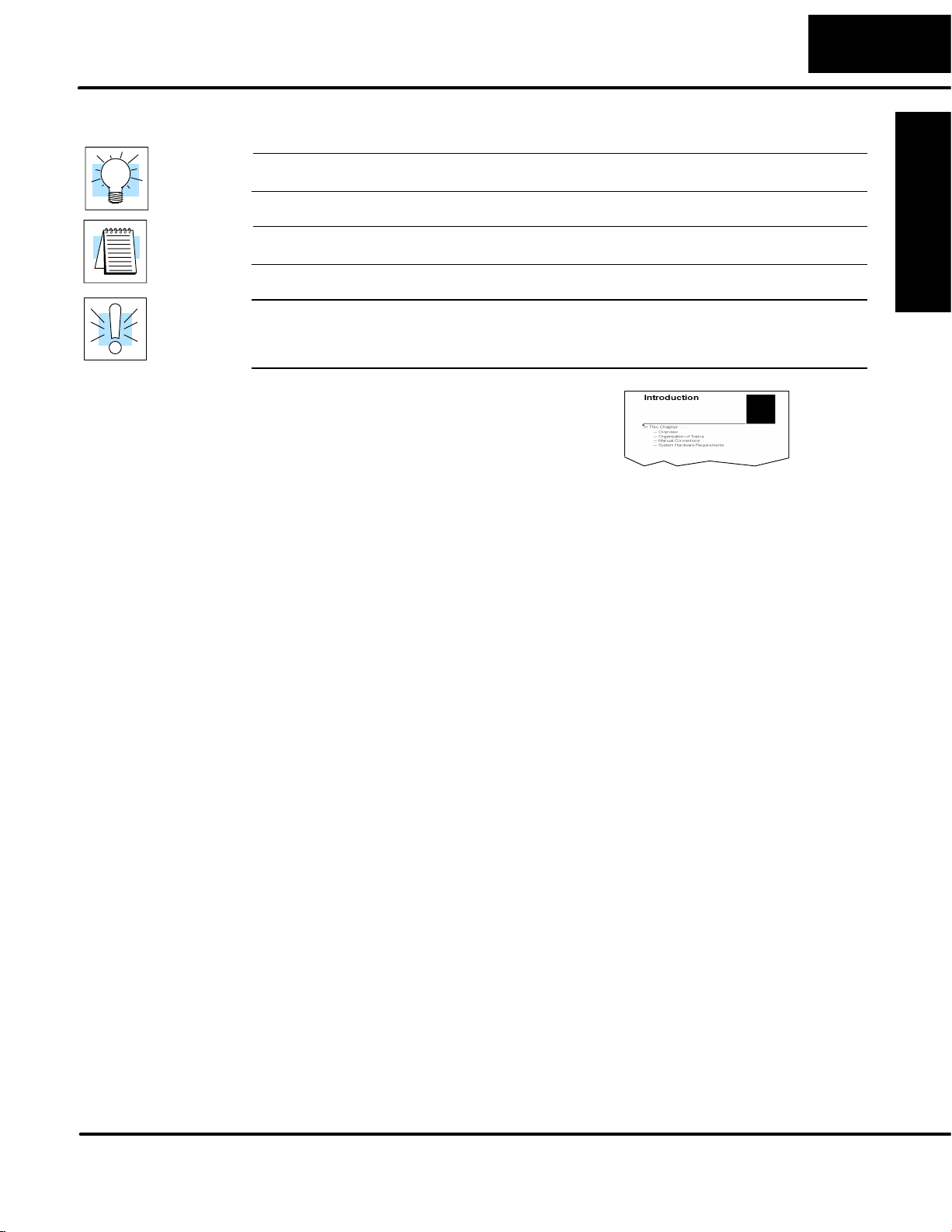
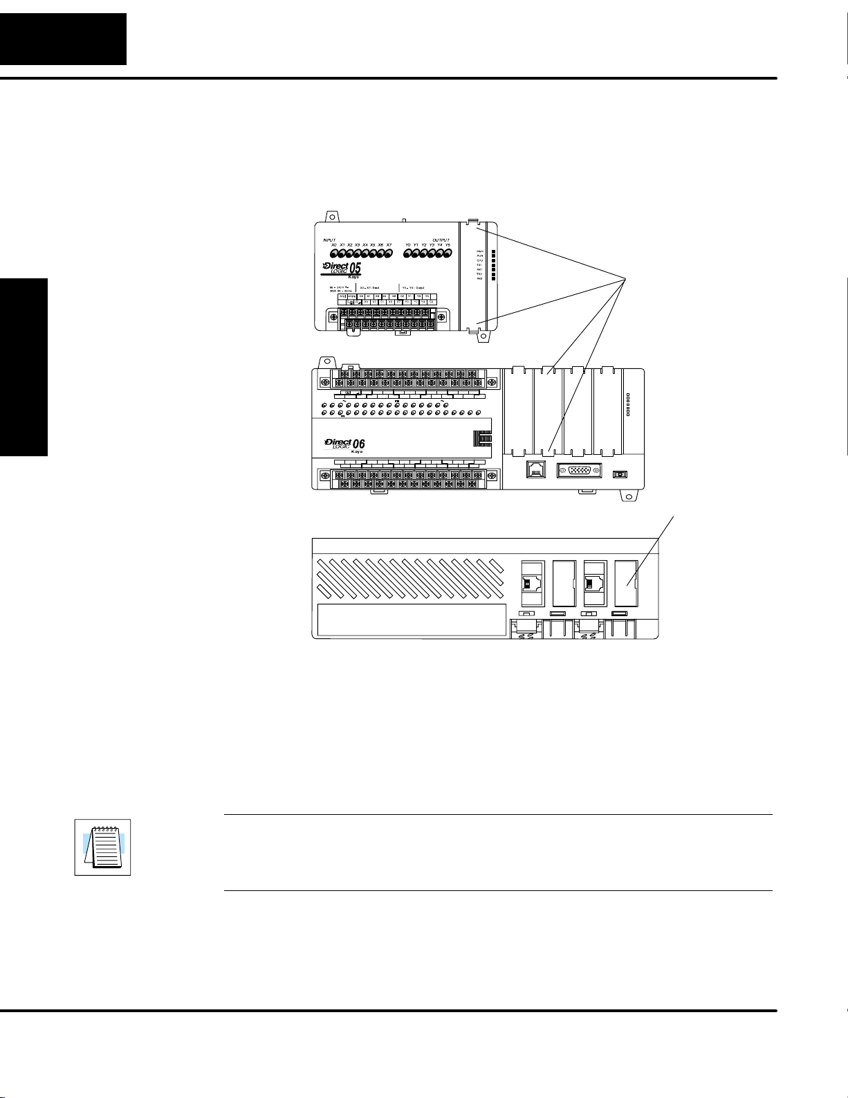
The following diagram shows the D0–DCM hardware components. The
communication parameters are configured using DirectSOFT32. There are no DIP
switches to set on this module.
The D0–DCM requires ladder logic programming to configure its communication
parameters, unless the default settings are acceptable for the application. If the
D0–DCM is to be used as a network master, you must use ladder logic code to
configure this parameter.
D0–DCM
Port 1: RS–232
Communication Port
Status Indicators
(shown below)
Installation and
Safety Guidelines
Port 2:
RS232/422/485
Communication Port
Status Indicators
TX1: Port 1
Transmitting Data
(Green)
RX1: Port 1
Receiving Data (Green);
Error (Red)
TX1
RX1
ERR
DATA COMM
PORT2
TX2
RX2
ERR
TX2: Port 2
Transmitting data
(Green)
RX2: Port 2
Receiving Data (Green);
Error (Red)
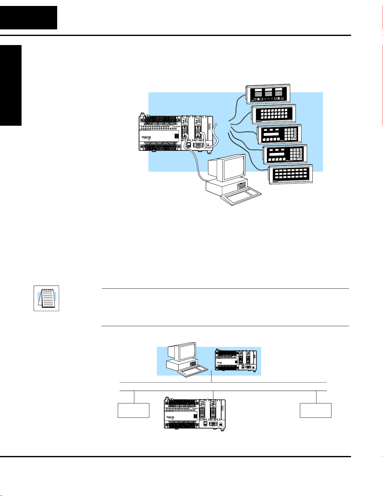
The D0–DCM Data Communications Module is a general purpose communications
interface that c an b e u sed i n a D L05/06 P LC s ystem. T he m odule c an g o in any o ption
slot. This module is primarily used for several reasons:
• As an extra general purpose communications port to connect to a personal
computer or operator interface
• As a network master or slave interface to a DirectNET network (port 2);
port 1 functions as a DirectNET slave only
• As a network master or slave interface to a MODBUS
port 1 functions as a MODBUS
R
RTU slave only
R
RTU network (port 2);
• As a K–sequence slave (both ports)
DL05/06 Data Communications Module, 1st Edition, 08/05
Page 13
Applications
As a DirectNET
Interface
1–5
Introduction
Introduction Installation and
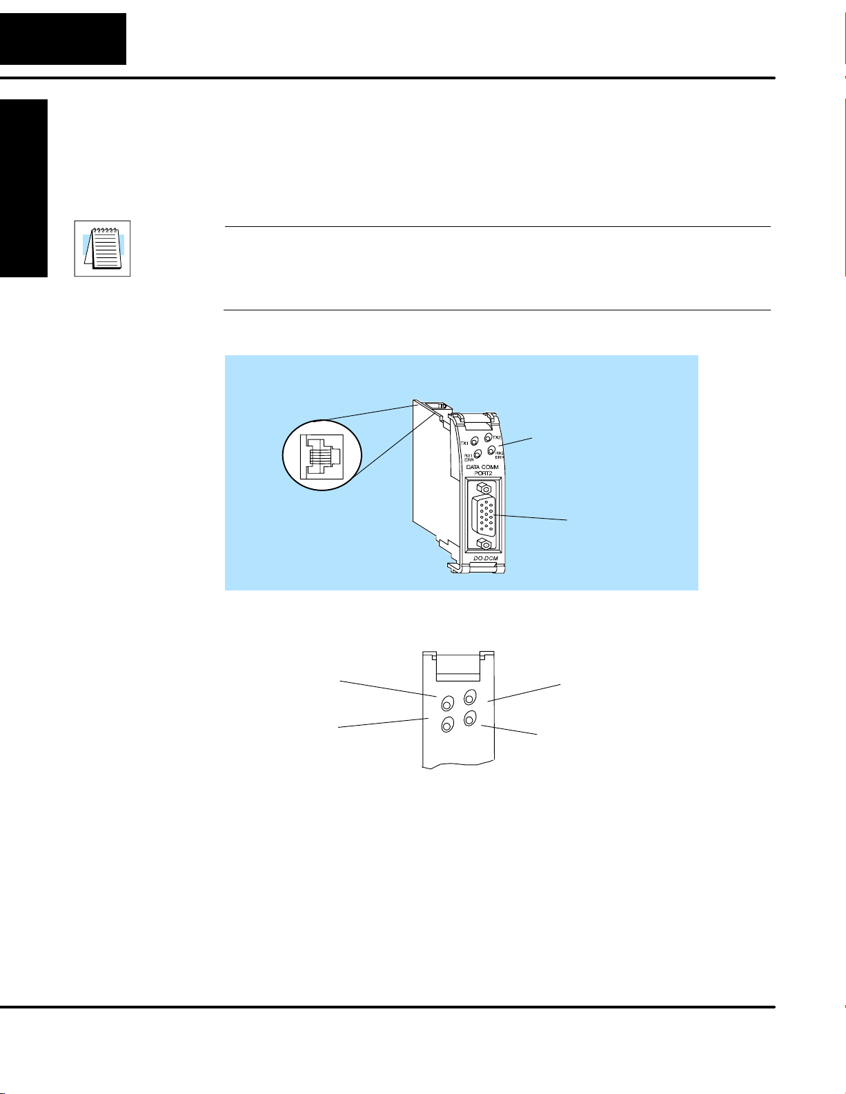
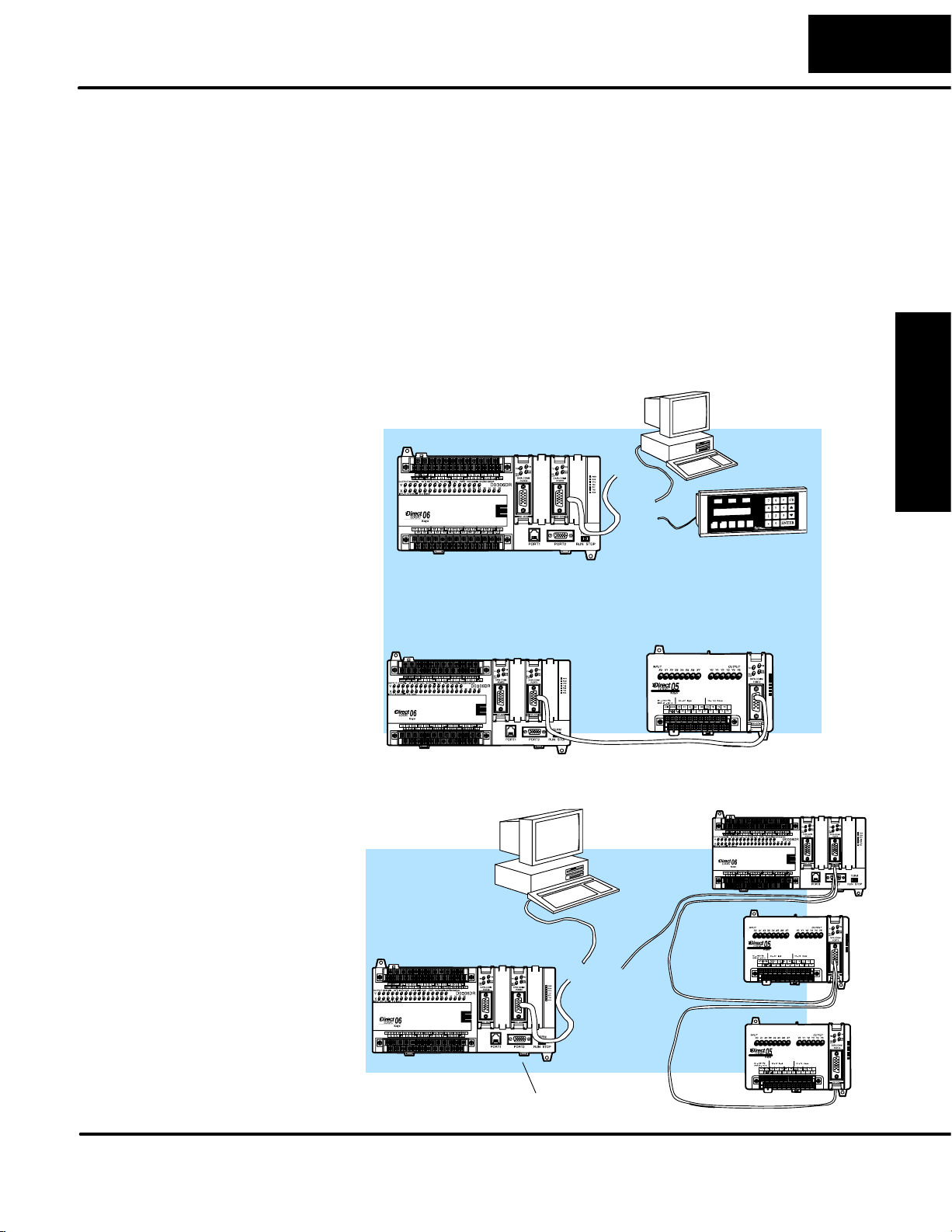
The D0–DCM can be used as a network interface for applications that require data to
be shared between PLCs, or between PLCs and an intelligent device (such as a host
computer). The D0–DCM can be configured as either a master or slave station and
allows you to upload or download virtually any type of system data including
Timer/Counter data, I/O information, and V-memory information.
DirectNET Master
Issues requests to slave
stations
PC or D0–DCM
master can
communicate with
DirectNET Slaves
Using a D0–DCM as a network Master
The D0–DCM can be used with a DL05 or
DL06 CPU to serve as a network master . A
master is the network station that initiates
requests for data from other stations on the
network). You simply use special RLL
instructions (RX and W X) inside o f your R LL
program to initiate the data exchange. The
D0–DCM takes communication requests
issued by the PLC program i nstructions and
automatically converts these requests into
network commands that read data from or
write data to another network station.
DirectNET Slaves
Slaves respond to the master’s request
Possible Slaves
S DL05/DL06 CPU (either port)
S DL05/DL06 CPU w/D0–DCM
S D2–240/250–1/260 CPU (either
port)
S D2–240/250–1/260 w/ D2–DCM
S D3–330/330P w/ DCU
S D3–340/350 (either port)
S D4–430/440 (bottom port)
S D4–450 (phone jack or bottom port)
S Any DL405 CPU w/ D4–DCM
Safety Guidelines
Using a D0–DCM as a network Slave
The D0–DCM can also be used with a
DL05 or DL06 CPU to serve as a network
slave station. In this case, the D0–DCM
“listens” to the network for any messages
that contain the D0–DCM’s address. The
D0–DCM deciphers the network
commands, carries out the request to read
or write data, and sends confirmation
and/or information to the master station.
DL05/06 Data Communications Module, 1st Edition, 08/05
Possible Masters
S DL05/06 CPU (port 2)
S DL05/06 CPU w/ D0–DCM
S 250–1/260 CPU (bottom port)
S D2–240/250–1/260 CPU
w/ D2–DCM
S D3–340/350 CPU (bottom
port)
S Any DL405 CPU w/ D4–DCM
S D4–450 CPU (bottom port)
S Host computer w/KEPDirect
for PLCs
Page 14
1–6
Introduction
As an Extra
Communication
Port
Introduction
As a MODBUSRTU
Network Interface
The D0–DCM ports are similiar to the ports on the DL05 and DL06 CPUs. In general,
if you can connect a device to the CPU ports, then you can also connect the same
device to the D0–DCM. These devices can be a variety of things, such as operator
interfaces or personal computers.
Quickly add extra
communication ports*
* Number of option modules is
limited by the DL06 available
power budget.
The D0–DCM can be used as a master or slave interface to connect your DL05/06
system to a M ODBUS RTU network. P ort 1 c an o nly s erve a s a MODBUS R TU s lave.
Port 2 can serve a s a M ODBUS R TU master o r slave. This m anual does not describe
the MODBUS protocol. We recommend that you reference the Gould MODBUS
Protocol Reference Guide (P1-MBUS-300 Rev. B) for details on the protocol. There
may be more recent editions of this manual, so check with your MODBUS supplier
before ordering the documentation.
Installation and
Safety Guidelines
DL05/06 Data Communications Module, 1st Edition, 08/05
For information about the MODBUS protocol see the Group Schneider Web site at:
www.schneiderautomation.com. At the main menu, select Support/Services,
Modbus, Modbus Technical Manuals, PI–MBUS–300 Modbus Protocol Reference
Guide or search for PIMBUS300.
MODBUS® Master
MODBUS Network using RTU Protocol
Network
Slave
DL06 Slave with
D0–DCM
As a slave station....
responding to network reĆ
quests
Network
Slave
Page 15

Installation, Network
Cabling and Module
Specifications
In This Chapter. . . .
— Inserting the D0–DCM into the PLC
— Building the Communication Cable
— Wiring Diagrams
— Module Specifications
1
2
Page 16
2–2
Installation and Setup
Inserting the D0–DCM into the PLC
D0–DCM Module
Installation
and Setup
Installation
Remove the front protective option slot cover by squeezing the pinch tabs and lifting
the cover off. Remove the top option slot cover using small flat–head screwdriver or
similiar device. Be sure PLC power is off when installing the D0–DCM module.
DL05
Front View
Pinch Tabs to
remove front
slot cover
0V
C0 C2 Y16Y14Y13Y11Y6Y4Y3Y1
C1 C3Y0 Y15Y12Y10 Y17Y7Y5Y2
2.0AOUTPUT: 6–240V
N.C.
40VA50–60HzPWR: 100–240V
D0–06DR
PWR
RUN
CPU
TX1
RX1
TX2
RX2
LGG
)
AC(N)24V
AC(L
50 – 60Hz2.0A,6 – 27V
Y
0 1 2 3 4 5 6 7 10 11 12 13 14 15 16 17 20 21 22 23
X
INPUT: 12 – 24V3 – 15mA
DL06
Front View
C0 C4C2X1 X3 X4 X6 X11X13X14 X16 X21 X23N.C.
C1 C3X2 X5 X7 X10 X12 X15X17 X20 X22X0 N.C.
PORT1 RUN STOP
PORT2
TERM
Remove top
slot cover with
small flat–head
screwdriver
Installation and
Safety Guidelines
DL06
Top View
Insert the module into the open slot in the DL05 or into any one of the four slots in the
DL06. Locate the module so the printed information is oriented in the same direction
as the markings on the PLC. Be careful to align the female connector on the printed
circuit board of the module with the male connector on the PLC mother board. Press
the module into the slot until the front of the module is flush with the front of the PLC.
Check the DL06 power budget to be sure that it remains within the power supply
limits before installing more modules.
NOTE: The DL05 CPU’s communication feature for the D0–DCM requires
DirectSOFT32 Version 3.0c (or later) and firmware version 5.00 (or later). The DL06
requires DirectSOFT32 version V4.0, build 16 (or later) and firmware version 1.90 (or
later). See our website for more information: www.automationdirect.com.
DL05/06 Data Communications Module, 1st Edition, 08/05
Page 17
Installation and Setup
Building the Communication Cable
There are several considerations that help determine the type of cable needed for
your D0–DCM application. The next few pages discuss these considerations in
detail.
Consideration 1:
Physical
Configuration
The D0–DCM can be used in either a point-to-point or multi-drop configuration. A
point-to-point connection only has two stations, a master and a slave. Use the
point-to-point configuration to connect a personal computer, an operator interface,
or an intelligent device to a single D0–DCM. You must also use this configuration
when you want to connect a DirectNET master station to a single DirectNET slave
station.
Use the multi-drop configuration to connect one master to two or more slaves (90
slave maximum).
Point to Point – RS–232C
PC or OI
Master
2–3
Installation
and Setup
D0–DCM Slave
DL06 Master
Multi-drop – RS–422/485
DirectNET or
MODBUS
RTU
Masters
or
or
DL05 Slave
DirectNET Slaves
Safety Guidelines
Installation and
D0–DCM
Data Communications Module, 1st Edition, 08/05
Page 18
2–4
Installation and Setup
Consideration 2:
Electrical
Specification
RS232C or
RS422/485
Consideration 3:
Cable Schematics
and Setup
Installation
Port 1
6
5
4
3
2
1
The D0–DCM can support RS–232 (ports 1 and 2) or RS–422/485 (port 2)
communication. Your application and configuration choice will help determine which
electrical specification is best for you. If you are using multi-drop, you must use RS–422
or RS–485. If you are using point-to-point, you may have a choice between RS–232C
and RS–422/485.
You can use RS–232 if the cable length is less than 50 feet and if the cable will not be
subjected to induced electrical noise that is commonly found near welders, large motors,
or other devices that create large magnetic fields.
You must use RS–422/485 for all other applications. RS–422/485 allows longer cable
distances (up to 3300 feet) and provides higher noise immunity.
Although the network configuration and electrical specification are important, the type of
devices being connected to the D0–DCM are just as important. The exact cable
schematic needed really depends on a combination of all three things.
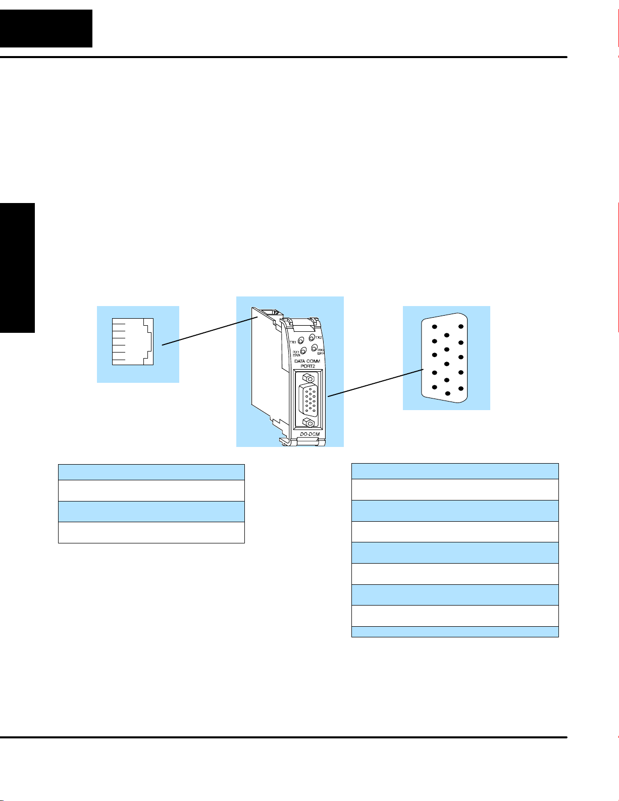
The following diagram shows the port pinouts for the D0–DCM.
D0–DCM Pinouts
Port 2
15
5
10
Port 1 Pin Descriptions
10V
25V
3 RXD Receive Data (RS–232)
4 TXD Transmit Data (RS–232)
5 RTS Request to Send
60V
Installation and
Safety Guidelines
RJ12 Phone Jack
Connector
11
6
1
15-pin Female
HD Connector
Port 2 Pin Descriptions
1 5V 5 VDC
2 TXD2 Transmit Data (RS–232)
3 RXD2 Receive Data (RS–232)
4 RTS2 Ready to Send (RS–232C
5 CTS2 Clear to Send (RS–232)
6 RXD2– Receive Data – (RS–422/485)
7 0V Logic Ground
8 0V Logic Ground
9 TXD2+ Transmit Data + (RS–422/485)
10 TXD2 – Transmit Data – (RS–422/485)
11 RTS2 + Request to Send + (RS–422/485)
12 RTS2 – Request to Send – (RS–422/485
13 RXD2 + Receive Data + (RS–422/485)
14 CTS2 + Clear to Send + (RS422/485)
15 CTS2 – Clear to Send – (RS–422/485)
DL05/06 Data Communications Module, 1st Edition, 08/05
Page 19
Installation and Setup
2–5
Consideration 4:
Cable Specifications
Consideration 5:
Installation
Guidelines
Although many types of cables may work for your application, we recommend you
use a cable that is constructed to offer a high degree of noise immunity . The following
specifications are to be used as a guideline.
Structure Shielded, twisted-pair. . . . . . . . . . . . . . . . . . . . . . .
(RS232 only uses two wires and a ground)
Conductor size 24 AWG or larger. . . . . . . . . . . . . . . . . .
Insulation Polyethylene. . . . . . . . . . . . . . . . . . . . . . .
Shield Copper braid or aluminum foil. . . . . . . . . . . . . . . . . . . . . . . . . .
Impedance 100W @ 1MHz. . . . . . . . . . . . . . . . . . . . . .
Capacitance 60pf / meter or less. . . . . . . . . . . . . . . . . . . .
Y our company may have guidelines for cable installation. If so, you must check those
before you begin the installation. Here are some general things to consider.
• Don’t run cable next to larger motors, high current switches, or
transformers. This may cause noise problems.
• Route the cable through an approved cable housing to minimize the risk
of accidental cable damage. Check local and national codes to choose
the correct method for your application.
• Consider redundant cabling if the application data is critical. This allows
you to quickly reconnect all stations while the primary cable is being
repaired.
Installation
and Setup
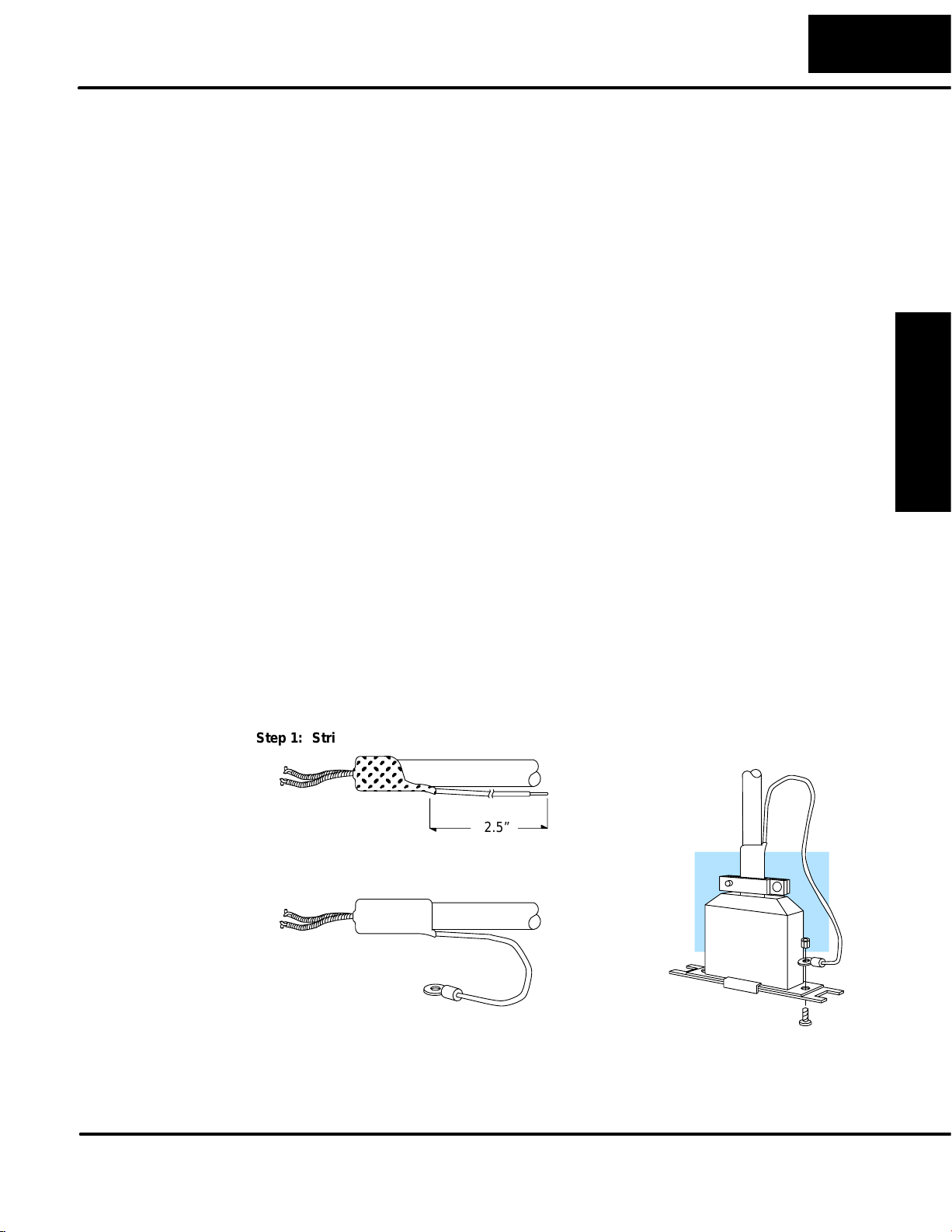
Cable Shield Grounding — It is important to ground the cable shield to minimize
the possibility of noise. The preferred method is to connect one end of the cable
shield to the connector housing. If noise problems are still present and you have a
good earth ground for the cabinet, you must connect one end of the shield to the
cabinet earth ground. Don’t ground both ends of the shield because this will create
induced noise on the cable.
Step 1: Strip back about 2.5” of the shield.
2.5”
Step 2: Crimp a ring connector onto the shield.
Step 3: Secure the shield to
the connector shell.
Safety Guidelines
Installation and
Data Communications Module, 1st Edition, 08/05
Page 20
2–6
Installation and Setup
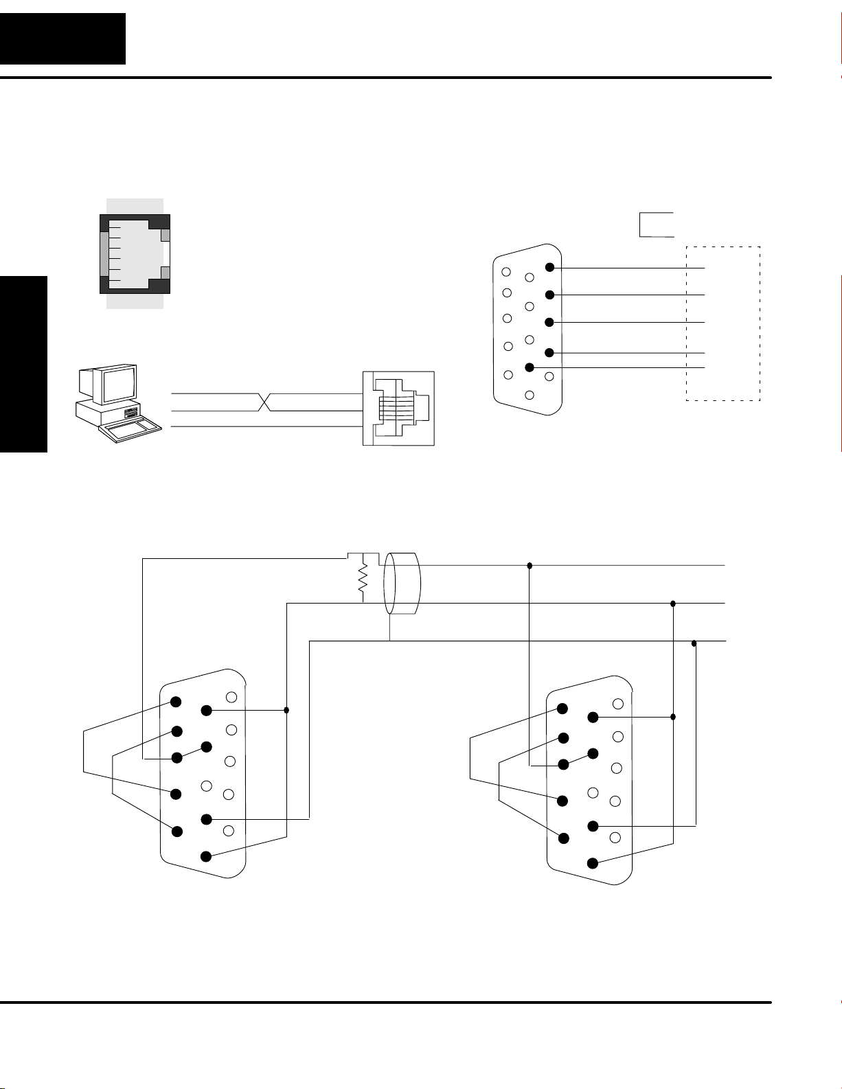
Wiring Diagrams
D0–DCM Port 1
RS–232 Network
Modular Connector
and Setup
Installation
123456
6-pin Female
TXD
RXD
0V
D0–DCM Port 2
RS–485 Network
TXD+ / RXD+
TXD 4
RXD 3
0V 1
Termination
Resistor
D0–DCM
PORT 1
D0–DCM Port 2
RS–232 Network
TXD+ / RXD+
15
OR
Loop
Back
5
CTS
10
RTS
4
RXD
3
TXD
2
7
11
Signal GND
1
6
RTS
RTS
CTS
TXD
RXD
GND
TXD+ / RXD+
CTS–
CTS+
Installation and
Safety Guidelines
RTS–
RTS+
15
RXD+
11
10
TXD+
7
TXD– / RXD–
Signal GND
Connect shield
5
TXD–
0V
1
RXD–
6
to signal ground
Cable: Use Belden
9841 or equivalent
CTS–
CTS+
RTS–
RTS+
TXD– / RXD–
15
10
TXD+
RXD+
7
11
6
5
TXD–
0V
1
RXD–
TXD– / RXD–
Signal GND
DL05/06 Data Communications Module, 1st Edition, 08/05
Page 21
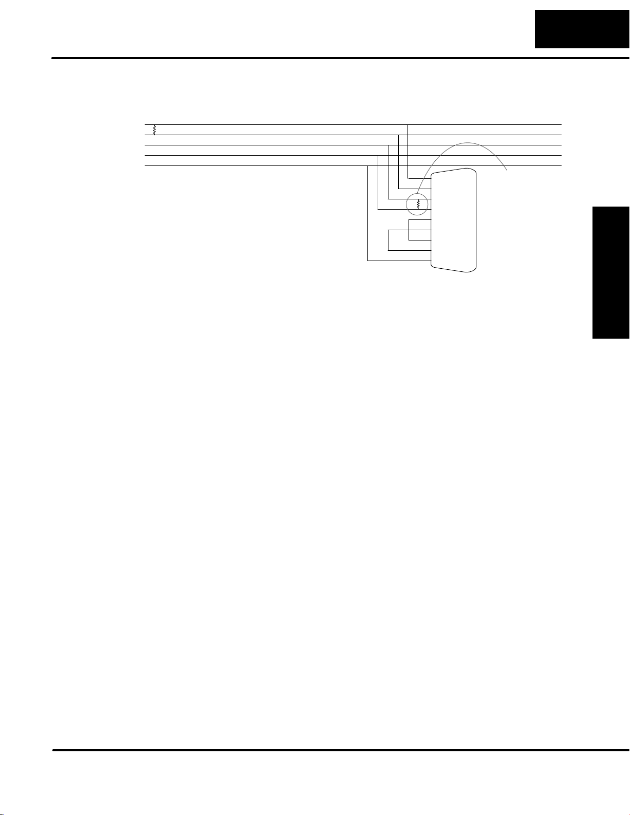
D0–DCM Port 2
RS–422 Network
Installation and Setup
RXD+
RXD–
TXD+
TXD–
Signal GND
PC/PLC Master
Cable: Use Belden
9729 or equivalent
9 TXD+
10 TXD–
13 RXD+
6 RXD–
11 RTS+
12 RTS–
14 CTS+
15 CTS–
70V
Termination
Resistor on
last slave only
PORT 2
(D0–DCM)
RS–422 Slave
RS–422/485 Multi-drop Termination Resistors — It is important you add
termination resistors at each end of the RS422/485 line. This helps reduce data
errors during data transmission. You must select resistors that match the cable
impedance. For example, a typical 22 AWG solid conductor cable with 4.5 twists per
foot has a typical impedance of about 120 ohm.
There are two ways to actually connect the resistors.
• Line-to-Line — this method balances the receive data lines (IN+ and
IN–) and requires one resistor at each end of the line. (The cable
diagrams we’ve provided show this method, but you can use either).
• Line-to-Ground — this method also balances the receive data lines, but
common mode noise rejection is improved significantly. This method
requires two resistors at each end of the line. Also, since there are two
resistors, the sum total of both resistors must match the cable
impedance.
2–7
Installation
and Setup
Data Communications Module, 1st Edition, 08/05
Safety Guidelines
Installation and
Page 22

2–8
Module Specifications
General
Specifications
and Setup
Installation
Installation and Setup
Power Budget Requirement 250mA @ 5 VDC
(not including external 5VDC consumption)
Maximum Number of Modules DL05: 1; DL06: 4
Operating Temperature 32° F to 131° F (0° to 55° C)
Storage Temperature –4° F to 158° F (–20° to 80° C)
Operating Humidity 5 to 95% (non-condensing)
Air Composition No corrosive gases permitted
Vibration MIL STD 810C, Method 514.2
Shock MIL STD 810C, Method 516.2
Voltage Isolation 1000 VAC, 1 minute duration
Insulation Resistance 10M ohms at 500 VDC
Port 1
Specifications
Installation and
Safety Guidelines
Noise Immunity NEMA ICS3–304, UL, CE, (FCC Class A)
Class 1, Division 2 (C1D2)
Weight 1.75 oz. (50g)
Connector 6–pin female modular (RJ12)
Communications RS–232
Protocol
(auto–dectection)
DirectNET slave
K-sequence slave
MODBUS® RTU slave
Station Number 0 – 247
Communication Data 8 data bits, 1 start bit, 1 stop bit (fixed)
Parity Bit None, Odd
Baud Rates 9600, 19200, 38400, 57600, 115200 bps
Transmit Mode ASCII, Hex
Maximum Distance RS–232: 50ft (15 meters)
Port 1
6
5
4
3
2
1
Port 1 Pin Descriptions
10V
25V
3 RXD Receive Data (RS–232)
4 TXD Transmit Data (RS–232)
5 RTS Request to Send
60V
DL05/06 Data Communications Module, 1st Edition, 08/05
Page 23

Port 2
Specifications
Installation and Setup
Connector
15–pin female high–density D–shell
Communications RS–232
RS–422/485
Protocol
(auto–dectection)
DirectNET master/slave
K-Sequence slave
MODBUS® RTU master/slave
Non–sequence (ASCII IN/OUT)
Station Number 0 – 247
Communication Data 8/7 data bits, 1 start bit, 1/2 stop bits
Parity Bit None, Odd, Even
Baud Rates 300, 600, 1200, 4800, 9600, 19200, 38400,
57600, 115200 bps
Transmit Mode ASCII, Hex
Communications Time–out Base time x (1–50)
2–9
Installation
and Setup
Status Indicators
Response Delay Time 0/2/5/10/20/50/100/500ms
Character Time–out 0–9999ms
Maximum Distance RS232 – 15 m
RS422/485 – 1000m
Port 2
15
11
5
10
1
6
Port 2 Pin Descriptions
1 5V 5 VDC
2 TXD2 Transmit Data (RS–232)
3 RXD2 Receive Data (RS–232)
4 RTS2 Ready to Send (RS–232)
5 CTS2 Clear to Send (RS–232)
6 RXD2– Receive Data – (RS–422/485)
7 0V Logic Ground
8 0V Logic Ground
9 TXD2+ Transmit Data + (RS–422/485)
10 TXD2 – Transmit Data – (RS–422/485)
11 RTS2 + Request to Send + (RS–422/485)
12 RTS2 – Request to Send – (RS–422/485
13 RXD2 + Receive Data + (RS–422/485)
14 CTS2 + Clear to Send + (RS422/485)
15 CTS2 – Clear to Send – (RS–422/485)
Indicator State Definition
TX1 (Green) ON Port 1 transmitting data
Safety Guidelines
Installation and
RX1 (Green)
ERR (Red)
ON
ON
Port 1 receiving data
Port 1 Timeout, NAK or Exception
Response
TX2 (Green) ON Port 2 transmitting data
RX2 (Green)
ERR (Red)
ON
ON
Port 2 receiving data
Port 2 Timeout, NAK or Exception
Response
Data Communications Module, 1st Edition, 08/05
Page 24

Page 25

D0–DCM Module
Configuration
Registers
In This Chapter. . . .
— DCM Port Configuration Registers
— DL05 Ladder Logic Port Setup Examples
— DL06 Ladder Logic Port Setup Examples
3
Page 26

3–2
D0–DCM Setup
DCM Port Configuration Registers
Module
Configuration
Registers
DCM Port
Configuration
The table below lists the special V-memory locations used by the DL05 and DL06
PLCs for the D0–DCM module. The following pages define each registers function.
Module Configuration
Parameters
Port 1–Transmit Mode
A
(ASCII/Hex), Protocol
Port 1–Station Address,
B
Baud Rate , Parity
Port 2–RTS On/Off Delay,
Transmit Mode (ASCII/
C
Hex), Protocol, Comm
Time–out, RS–485 Mode
Select
Port 2–Station Address,
D
Baud Rate, Data Bit , Stop
Bit , Parity
Port 2–Character Time–
E
out
Port1/Port 2 – Setup
F
Completion Code
Port 1/Port 2–
G
Reset Time–out
Word
Offset
+0000 V7700 V700 V710 V720 V730
+0001 V7701 V701 V711 V721 V731
+0002 V7702 V702 V712 V722 V732
+0003 V7703 V703 V713 V723 V733
+0006 V7706 V706 V716 V726 V736
+0007 V7707 V707 V717 V727 V737
DL05 and DL06 Option Slot
DL05
V7730 V7730 V7731 V7732 V7733
DL06
Slot 1
DL06
Slot 2
DL06
Slot 3
DL06
Slot 4
Comm Port
Default
Configuration
Parameters
Installation and
Safety Guidelines
On power up, the DCM will write the necessary data to the V–memory configuration
registers to result with the following default port communications parameters. If you
need to change any of the default settings, you must use ladder logic code to update
the appropriate configuration register.
Default Settings
Parameter Port 1 Port 2
Baud Rate 9600bps 19200bps
Parity Odd
Protocol K–Sequence/DirectNet/MODBUS
(auto–detect)
Station Address 1
Data Bits 8 (fixed) 8
Stop Bits 1 (fixed) 1
DL05/06 Data Communications Module, 1st Edition, 08/05
Page 27

3–3
D0–DCM Setup
Protocol Selection:
Communications Port for DirectSOFT32 Programming: If you plan to program the CPU
through the D0–DCM, then you can use either DirectNET protocol or our proprietary
K-sequence protocol.
Computer or Operator Interface: If you’re using the D0–DCM to connect a computer or
operator interface, check your documentation to see which protocol the PC or OI is using.
MODBUS® RTU: The D0–DCM can serve as a MODBUS® slave (port1 and 2) or as a
MODBUSmaster (port 2 only).
Communication Timeout:
developing your own DirectNET programs. By disabling the timeout, you can send one
DirectNET component without any communication timeout problems. If you have this
timeout disabled and a communication error does occur, you must restart communications
by sending a retry or an End of Transmission (EOT) command. If you want to know more, see
the DirectNET manual for details.
Transmit Mode:
fastest communication possible, use HEX mode, which is the default. The difference is in the way
the data is represented. The same data is twice as long in ASCII format, so if there’s more data, it
takes longer to transfer. If you have a device on the network that requires ASCII mode, then
configure the DCM for ASCII mode, otherwise, use HEX mode.
Baud Rate:
115.2Kbps. All stations must have the same baud rate before the communications will
operate correctly. Usually, you should use the highest baud rate possible unless noise
problems appear. If noise problems appear, try reducing the baud rates.
Parity:
RTS Delay Times:
waits to send the data after it has raised the RTS signal line. This is normally set to 0, and is
typically only adjusted if you are using the D0–DCM with a radio modem. If you are using the
D0–DCM with a radio modem, check your modem documentation to help you choose the
proper setting. Also, if you’re considering the use of a modem, check out Appendix D. It may
be of some help. RTS Off Delay – the delay time specifies the amount of time the D0–DCM
will wait to reset the RTS line after sending the data.
Address Selection
have a unique address. If you’re using the D0–DCM as a master, make sure you select
address 0. For example, a RLL communications program, the DirectSOFT32 Programming
Software, and our KEPDirect for PLCs all use the decimal equivalent of the HEX address. It’s
easy to convert from hex to decimal.
Choose between none, even and odd parity for error checking.
Select between ASCII and HEX modes of data representation. If you want the
There are several baud rate selections available ranging from 300bps to
On Delay – The delay time specifies the amount of time the D0–DCM
: The addresses do not have to be consecutive, but each station must
Communication Timeout Disable is normally used only if you’re
Configuration
DCM Port
Safety Guidelines
Installation and
DL05/06 Data Communications Module, 1st Edition, 08/05
Page 28

3–4
D0–DCM Setup
A: Port 1 –
Transmit Mode,
Protocol
DCM Port
Configuration
Use word +0000 to set Port 1:
• K–Sequence slave, DirectNET slave or MODBUS RTU slave protocol
(or auto–detect for all three protocols)
• HEX or ASCII transmit mode
word +0000
1
5
MSB LSB
Protocol
Transmit Mode
Set all unused bits to zero.
Port 1: Transmit Mode
Mode Bit 3
HEX Mode 0
ASCII Mode 1
Port 1: Protocol
Protocol Bit 7–4
(Hex)
K–Sequence 8 1 0 0 0
DirectNet 4 0 1 0 0
MODBUS RTU 2 0 0 1 0
K–Seq / D–Net
/MODBUS RTU
E 1 1 1 0
Bit 7 Bit 6 Bit 5 Bit 4
07654321
Installation and
Safety Guidelines
DL05/06 Data Communications Module, 1st Edition, 08/05
Page 29

D0–DCM Setup
3–5
B: Port 1 –
Station Address,
Baud Rate,
Parity
Use word +0001 to set Port 1:
• Station address ranges from 0–247 (00–F7 Hex)
• Baud rates ranging from 9.6K to 115.2K bps
• Odd or No parity
word +0001
1514131
MSB
Parity
Set all unused bits to zero.
Address Bit 7 Bit 6 Bit 5 Bit 4 Bit 3 Bit 2 Bit 1 Bit 0
00 0 0 0 0 0 0 0 0
01 0 0 0 0 0 0 0 1
02 0 0 0 0 0 0 1 0
– – – – –
F6 1 1 1 1 0 1 1 0
F7 1 1 1 1 0 1 1 1
111
0
2
987654321
Baud
Rate
Station
Address
0
LSB
Port 1: Station Address
Configuration
DCM Port
Port 1: Baud Rate
Baud Rate Bit 10 Bit 9 Bit 8
9.6 K bps 0 0 0
19.K bps 0 0 1
38.4K bps 0 1 0
57.6K bps 0 1 1
115.2K bps 1 0 0
Port 1: Parity
Parity Bit 14
No Parity 0
Odd Parity 1
DL05/06 Data Communications Module, 1st Edition, 08/05
Safety Guidelines
Installation and
Page 30

3–6
D0–DCM Setup
C: Port 2 –
RTS On/Off delay,
Transmit Mode,
Protocol,
Comm Time–out,
RS–485 Mode
Use word +0002 to set Port 2:
• K–Sequence slave, DirectNET slave or MODBUS RTU slave protocol
(or auto–detect for all three protocols)
• HEX or ASCII transmit mode
• RTS On and Off delay times
• Communication Time–out
• Echo Suppression
word +0002
1514131
MSB
RTS on
delay
111
0
2
Echo
Suppression
987654321
Comm
Time–out
Protocol
Transmit
Mode
0
LSB
RTS off
delay
Set all unused bits to zero.
DCM Port
Configuration
Installation and
Safety Guidelines
Port 2: RTS Off Delay
Time (ms) Bit 2 Bit 1 Bit 0
0 0 0 0
2 0 0 1
5 0 1 0
10 0 1 1
20 1 0 0
50 1 0 1
100 1 1 0
500 1 1 1
Base Time–out for K–Seq/D–Net = 800ms
Base Time–out for MODBUS = 500ms
Port 2: Transmit Mode
Mode Bit 3
HEX Mode 0
ASCII Mode 1
DL05/06 Data Communications Module, 1st Edition, 08/05
Page 31

Port 2: Protocol
Protocol Bit 7–4
(Hex)
K–Sequence 8 1 0 0 0
DirectNet 4 0 1 0 0
MODBUS RTU 2 0 0 1 0
Non–Sequence 1 0 0 0 1
K–Seq / D–Net
/MODBUS RTU
K–Seq, D–Net,
MODBUS RTU
Base Time x 1 0 0 0 0
Base Time x 1.2 2 0 0 1
Base Time x 1.5 5 0 1 0
Base Time x 2 10 0 1 1
Base Time x 5 20 1 0 0
Base Time x 10 50 1 0 1
Base Time x 20 100 1 1 0
Base Time x 50 500 1 1 1
E 1 1 1 0
Port 2: Communication Time–out (ms)
Bit 7 Bit 6 Bit 5 Bit 4
Non–Sequence
Protocol
Bit 10 Bit 9 Bit 8
3–7
D0–DCM Setup
Configuration
DCM Port
Port 2: Echo Suppression
Mode Bit 11
RS–422/485: 4–wire
RS–232
RS–485: 2–wire 1
Port 2: RTS On Delay
Time (ms) Bit 14 Bit 13 Bit 12
0 0 0 0
2 0 0 1
5 0 1 0
10 0 1 1
20 1 0 0
50 1 0 1
100 1 1 0
500 1 1 1
0
Safety Guidelines
Installation and
DL05/06 Data Communications Module, 1st Edition, 08/05
Page 32

3–8
D0–DCM Setup
D: Port 2 –
Station Address,
Baud Rate,
Data Bit,
Stop Bit,
Parity
DCM Port
Configuration
Use word +0003 to set Port 2:
• Station address ranges from 0–247 (00–F7 Hex)
• Baud rates ranging from 9.6K to 115.2K bps
• Data Bit Length (7 or 8 bits)
• Stop Bit Length (1 or 2 bits)
• Odd, Even or No Parity
word +0003
1514131
MSB
Parity
Stop
Bit
Address Bit 7 Bit 6 Bit 5 Bit 4 Bit 3 Bit 2 Bit 1 Bit 0
00 0 0 0 0 0 0 0 0
01 0 0 0 0 0 0 0 1
02 0 0 0 0 0 0 1 0
–––––
F6 1 1 1 1 0 1 1 0
F7 1 1 1 1 0 1 1 1
111
2
Data
Bit
0
987654321
Baud
Rate
Station
Address
Set all unused bits to zero.
0
LSB
Port 2: Station Address
Installation and
Safety Guidelines
DL05/06 Data Communications Module, 1st Edition, 08/05
Port 2: Baud Rate
Baud Rate Bit 11 Bit 10 Bit 9 Bit 8
300 bps 0 0 0 0
600 bps 0 0 0 1
1200 bps 0 0 1 0
2400 bps 0 0 1 1
4800 bps 0 1 0 0
9600 bps 0 1 0 1
19.K bps 0 1 1 0
38.4K bps 0 1 1 1
57.6K bps 1 0 0 0
115.2K bps 1 0 0 1
Page 33

Port 2: Data Bit
Length Bit 12
8 Bit 0
7 Bit 1
Port 2: Stop Bit
Length Bit 13
1 Bit 0
2 Bit 1
Port 2: Parity
Parity Bit 15 Bit 14
No Parity 0 0
Odd Parity 0 1
Even Parity 1 0
3–9
D0–DCM Setup
Configuration
DCM Port
E: Port 2 –
Character
Time–out
Use word +0006 to set Port 2:
• Character Time–out (BCD)
This parameter is used when the DCM is used as a MODBUS RTU master.
word +0006
1514131
MSB
Bit 15–0 time
0 3.5 characters
1–9999 (BCD) time–out (ms)
111
0
2
Port 2: Character Time–out
987654321
Character
Time–out
(BCD)
0
LSB
Safety Guidelines
Installation and
DL05/06 Data Communications Module, 1st Edition, 08/05
Page 34

3–10
Port 1: Bit 0 7
D0–DCM Setup
F: Port 1 and 2
Setup and
Completion Code
G: Port 1 and 2
Reset Time–out
Word +0007 is used for Port 1 and Port 2 to :
• request that the DCM recognizes changes in the port(s) communication
parameters from default or previous settings
• confirm that Port 1 and Port 2 configuration is complete
word +0007
1
5
MSB
Set all unused
bits to zero.
Loading a K0055 (BCD) into word +0007 will request that the DCM recognizes (looks for) new
or desired port communication parameters that are written to the DCM port configuration
registers. If the requested changes are valid, a 00AA (hex) will then be written to word +0007.
If the desired or new communications are invalid or out of range, an error code 00E* (Hex) will
be written to word +0007. The last digits indicate the address that has an error. For example,
error code 00E2 means that word +0002 has an error.
Use word +0024 to set Port 1 and Port 2:
• Reset Time–out in seconds
Port Configuration
Completion Code
07654321
LSB
DCM Port
Configuration
Installation and
Safety Guidelines
The communication port will reset after the specified time after the port goes from the BUSY
state to the IDLE state.
word +0024
1514131
MSB
Port 1: Bit 0–7
Port 2: Bit 15–8
111
0
2
Port 2 Reset
Time–out
(BCD)
Port Time(s) Function
987654321
Port 1 Reset
Time–out
(BCD)
Reset Time–out
0 Disable
1–99 Enable
0
LSB
DL05/06 Data Communications Module, 1st Edition, 08/05
Page 35

DL05 Port Setup Examples
3–11
D0–DCM Setup
Port 1 Example:
(This port can
serve as slave
only)
Port 2 Example:
Slave Mode
SP0
SP0
LD
KE0
OUT
V7700
LD
K4001
OUT
V7701
LD
K55
OUT
V7707
LD
KE0
Selects auto–detect protocol mode
(K–seq, D–Net and MODBUS) and
HEX transmit mode.
Write configuration data into V7700.
Selects station address 1, baud rate
of 9600bps and odd parity.
Write configuration data into V7701.
K55 is the port setup completion
code that must be used to request
that the CPU recognizes the
new/desired port parameters
Write configuration data into V7707.
Selects auto–detect protocol mode (K–seq,
D–Net and MODBUS), HEX transmit mode,
RTS On/Off delay times are set to zero and
RS–422/485 (4–wire) / RS–232
Configuration
DCM Port
OUT
V7702
Write configuration data into V7702.
Selects station address 1, baud rate
LD
K4601
OUT
V7703
of 19200bps, odd parity, 8–bit data
length and 1 stop bit.
Write configuration data into V7703.
K55 is the port setup completion
LD
K55
code that must be used to request
that the CPU recognizes the
new/desired port parameters
OUT
V7707
Write configuration data into V7707.
DL05/06 Data Communications Module, 1st Edition, 08/05
Safety Guidelines
Installation and
Page 36

3–12
D0–DCM Setup
Port 2 Example:
DirectNet Master
Port 2 Example:
MODBUS RTU
Master
DCM Port
Configuration
SP0
SP0
LD
K40
OUT
V7702
LD
K4601
OUT
V7703
LD
K55
OUT
V7707
LD
K20
Selects DirectNet protocol, HEX transmit
mode, RTS On/Off delay times are set to
zero and RS–422/485 (4–wire) / RS–232
Write configuration data into V7702.
Selects station address 1, baud rate
of 19200bps, odd parity, 8–bit data
length and 1 stop bit.
Write configuration data into V7703.
K55 is the port setup completion
code that must be used to request
that the CPU recognizes the
new/desired port parameters
Write configuration data into V7707.
Selects MODBUS protocol, HEX transmit
mode, RTS On/Off delay times are set to
zero and RS–422/485 (4–wire) / RS–232
Installation and
Safety Guidelines
OUT
V7702
LD
K4601
OUT
V7703
LD
K0
OUT
V7706
LD
K55
OUT
V7707
Write configuration data into V7702.
Selects station address 1, baud rate
of 19200bps, odd parity, 8–bit data
length and 1 stop bit.
Write configuration data into V7703.
Selects 3.5 characters length
time–out.
Write configuration data into V7706.
K55 is the port setup completion
code that must be used to request
that the CPU recognizes the
new/desired port parameters
Write configuration data into V7707.
DL05/06 Data Communications Module, 1st Edition, 08/05
Page 37

DL06 Port Setup Examples
The following examples assumes the D0–DCM is installed in slot 1.
3–13
D0–DCM Setup
Port 1 Example:
Slave Mode Only
Port 2 Example:
Slave Mode
SP0
SP0
LD
KE0
OUT
V700
LD
K4001
OUT
V701
LD
K55
OUT
V707
LD
KE0
OUT
V702
Selects auto–detect protocol mode
(K–seq, D–Net and MODBUS) and
HEX transmit mode.
Write configuration data into V700 (based
on module slot location).
Selects station address 1, baud rate
of 9600bps and odd parity.
Write configuration data into V701 (based
on module slot location).
K55 is the port setup completion
code that must be used to request
that the CPU recognizes the
new/desired port parameters
Write configuration data into V707 (based
on module slot location).
Selects auto–detect protocol mode (K–seq,
D–Net and MODBUS), HEX transmit mode,
RTS On/Off delay times are set to zero and
RS–422/485 (4–wire) / RS–232
Write configuration data into V702 (based
on module slot location).
Configuration
DCM Port
Safety Guidelines
Installation and
Selects station address 1, baud rate
LD
K4601
OUT
V703
of 19200bps, odd parity, 8–bit data
length and 1 stop bit.
Write configuration data into V703 (based
on module slot location).
K55 is the port setup completion
LD
K55
code that must be used to request
that the CPU recognizes the
new/desired port parameters
OUT
V707
Write configuration data into V707 (based
on module slot location).
DL05/06 Data Communications Module, 1st Edition, 08/05
Page 38

3–14
D0–DCM Setup
Port 2 Example:
DirectNet Master
Port 2 Example:
MODBUS RTU
Master
DCM Port
Configuration
SP0
SP0
LD
K40
OUT
V702
LD
K4601
OUT
V703
LD
K55
OUT
V707
LD
K20
OUT
V702
Selects DirectNet protocol, HEX transmit
mode, RTS On/Off delay times are set to
zero and RS–422/485 (4–wire) / RS–232
Write configuration data into V702 (based
on module slot location).
Selects station address 1, baud rate
of 19200bps, odd parity, 8–bit data
length and 1 stop bit.
Write configuration data into V703 (based
on module slot location).
K55 is the port setup completion
code that must be used to request
that the CPU recognizes the
new/desired port parameters
Write configuration data into V707 (based
on module slot location).
Selects MODBUS protocol, HEX transmit
mode, RTS On/Off delay times are set to
zero and RS–422/485 (4–wire) / RS–232C
Write configuration data into V702 (based
on module slot location).
Installation and
Safety Guidelines
DL05/06 Data Communications Module, 1st Edition, 08/05
LD
K4601
OUT
V703
LD
K0
OUT
V706
LD
K55
OUT
V707
Selects station address 1, baud rate
of 19200bps, odd parity, 8–bit data
length and 1 stop bit.
Write configuration data into V703 (based
on module slot location).
Selects 3.5 characters length
time–out.
Write configuration data into V706 (based
on module slot location).
K55 is the port setup completion
code that must be used to request
that the CPU recognizes the
new/desired port parameters
Write configuration data into V707 (based
on module slot location).
Page 39

RLL Programming for
Communications
In This Chapter. . . .
— PLC-to-PLC Communications
— How RLL is Used for Communications
— Network Instructions
1
4
— Addressing the Different Memory Types
— Special Relays for Communications
— Example Program with One Read Instruction
— Example Program with One Write Instruction
— Integrating Multiple Read and Write Instructions
Page 40

4–2
PLC-to-PLC Communications
Getting Started
How RLL is Used for Communications
RLL Programming for Communications
This chapter steps you through the development of a Relay Ladder Logic (RLL)
program to enable one PLC to communicate with another PLC. For the experienced
programmer of DirectLOGIC PLCs, the communication programs presented in this
chapter will be simple to follow . If you have never programmed a DirectLOGIC PLC,
you may want to refer to the DirectSOFT32 Programming Software User Manual
and the User Manual for your PLC for additional information.
NOTE: The programs described in this chapter are not used for communication
between a PC and a PLC. For PC-to-PLC communications, please see the product
documentation for the PC software you are using.
DirectSOFT32 Programming Software provides Read and Write instructions
(RX/WX) for PLC-to-PLC communication over a network. The Read and Write
instructions are part of the ladder logic program running in the CPU of the initiating,
or master, PLC. These instructions tell the initiating CPU to send a message over the
serial network to a responding, or slave, PLC. The initiating PLC’s Read or Write
communication finds its destination by the slave address of the responding PLC.
Guidelines
User Application
RLL Programming
for Communications
Master DCM
O
O
U
CPU CPU
T
P
U
T
Slave 1
I
N
P
U
T
O
I
U
N
T
P
P
U
U
T
T
O
U
Slave 2
T
P
U
T
W
r
R
e
a
d
I
U
N
i
t
e
T
P
P
U
U
T
T
Slave 3
CPUCPU
NOTE: When all slave’s addresses are set to 0 (zero), the master D0–DCM can write
data to all slaves at the same time using the WX instruction. This is referred to as
“broadcast mode”. If this mode is used, the master DCM cannot use the RX
instruction to read data from individual slaves.
I
N
P
U
T
I
N
P
U
T
O
U
T
P
U
T
O
E
U
C
O
M
T
P
U
T
DL05/06 Data Communications Module, 1st Edition, 08/05
Page 41

Network Instructions
4–3
RLL Programming for Communications
Read (RX) and
Write (WX)
Instructions
Building the
Read (RX) or
Write (WX)
Routine
The Read (RX) and Write (WX) instructions are used by the master PLC to Read a
block of data from another PLC or Write a block of data to another PLC. To perform
their functions, the RX and WX boxes must be preceded in the ladder logic program
by two Load instructions and one Load Address instruction.
The Load and Load Address instructions load communication parameters into the
accumulator and the first and second level of the accumulator stack. The RX or
WX instruction takes these parameters from the stack and the accumulator and
prepares the data to be sent over the network. If you need to know more about the
function of the accumulator and the accumulator stack, refer to the User Manual for
your PLC.
For network communications, you build
the Read (RX) or Write (WX) instructions
into a routine which requires the four
instructions you see to the right. The
function of each of these instructions is
explained below or on the next page. They
LD
A aaa
LD
A aaa
must be used in the sequence shown.
LDA
O aaa
RX or WX
A aaa
User Application
Guidelines
The First LD
Instruction
The first Load (LD) instruction accepts either a constant or a variable. Use a “K” to
designate the number as a constant. Use a “V” if you are entering the address of a
register. The contents of that register perform the same function as the constant
shown below . For example, you could use V2000 in place of K0114. If the contents of
V2000 is the number “114,” the function would be the same. Using a variable allows
changing parameters while the program is running. It is recommended, however, t o
use a constant when possible.
DCM Slot Number
Master PLC
Upper Byte
K
1140
Lower Byte
SlaveMaster DCM
Slave Address # (Hex)
Slave Device on Network
LD
K114
for Communications
RLL Programming
DL05/06 Data Communications Module, 1st Edition, 08/05
Page 42

4–4
RLL Programming for Communications
The Second LD
Instruction
Getting Started
The LDA
Instruction
Guidelines
User Application
RLL Programming
for Communications
The second Load (LD) instruction
determines the length of the data block to
be transmitted during the Read or Write
communication. This instruction will also
accept two data types. Use a “K” to
designate the number as a constant. Use a
“V” if you are entering the address of a
register.
For Word Memory data, you must use a
multiple of two bytes between 2 and 128.
For Bit Memory data, you can use any
multiple of one byte between 1 and 128.
For more information about addressing
Word and Bit Memory, see page 4-6.
PLC Memory
The Load Address (LDA) instruction
specifies the V-memory address of the
beginning memory register in the master
PLC. The data block to be transmitted will
begin at this address and extend the
number of bytes specified in the preceding
LD instruction. The leading “O” indicates
this is an octal number. Simply substitute
the letter “O” for the “V” in the V-memory
designation. For example, V40600
becomes O40600.
Read instructions copy the data block from
the slave PLC memory into the master PLC
memory.
Write instructions copy the data block from
the master PLC memory into the slave PLC
memory.
LD
K114
LD
K8
4 words = 8 bytes
LD
K114
LD
K8
LDA
O40600
Master PLC
DL05/06 Data Communications Module, 1st Edition, 08/05
V40577
V40600
V40601
V40602
V40603
V40604
Page 43

RLL Programming for Communications
s
e
4–5
Read (RX)
Instruction
The Read (RX) instruction specifies the
memory location to be read from the slave
PLC.
A block of data is read that begins at the
specified memory location and extends the
number of bytes specified in the second LD
instruction.
In this example, the eight byte block of data
beginning at C100 and ending at C177 in
the slave PLC is read (copied) into the
master PLC’s memory beginning at
V40600.
ad
e
R
Master PLC
V40577
V40600
V40601
V40602
V40603
V40604
byte
word 4 words = 8 bytes
byte
Slave PLC
bit
LD
LD
LDA
RX
C100C177
bit
K114
K8
O40600
C100
V40603
V40604
V40605
V40606
V40607
V40610
User Application
Guidelines
Write (WX)
Instruction
The Write (WX) instruction specifies the
memory location to be written to in the
slave PLC.
A block of data is written that begins at the
specified memory location and extends the
number of bytes specified in the second LD
instruction.
In the example, the 8-byte block of data
beginning at V40600 and ending at V40603
in the master PLC is written (copied) into the
lave PLC’s memory beginning at C100 and
nding at C177.
r
i
t
e
Master PLC
byte
W
V40577
V40600
V40601
V40602
V40603
V40604
byte
Slave PLC
bit
C100C177
LD
LD
LDA
WX
bit
K114
K8
O40600
C100
V40603
V40604
V40605
V40606
V40607
V40610
for Communications
RLL Programming
word
4 words = 8 bytes
DL05/06 Data Communications Module, 1st Edition, 08/05
Page 44

4–6
Addressing the Different Memory Types
Getting Started
Bit Memory
Word Memory
and Aliases
RLL Programming for Communications
Some data types are inherently 16 bits long, for example timer and counter current
values. Other data types are 1 bit long, for example: discrete inputs and outputs.
Word-length and bit-length data are mapped into Word Memory, also known as
V-memory, which allows you to address any of the different memory types as 16-bit
words.
Bit memory can be addressed in Read and Write instructions by the name of the first
bit of any byte. If your second LD instruction contains the constant K8, eight bytes will
be transmitted. If you use C0 in your RX or WX instruction, you will transmit the eight
bytes from C0 through C77.
In the example below, V40600 is the V-memory designation for the sixteen bits from
C0 through C17. Aliases are a convenient substitute for V-memory designations,
and can be used interchangeably in Read and Write instructions. VC0 is the alias for
V40600. Either nomenclature addresses the same 16 bits.
The alias is simply the name of the first bit in a group of sixteen bits, with V added as a
prefix. For example, VC0 represents the 16 bits beginning with C0. Word Memory,
Bit Memory and Aliases all use the octal numbering system.
Word Memory Address V40600
Guidelines
User Application
RLL Programming
for Communications
= VC0 (Alias)
V40601 = VC20
V40602 = VC40
V40603 = VC60
C1C2C3C4C5C6C7C10C11C12C13C14C15C16C17 C0
C37 C36 C35 C34 C33 C32 C31 C30 C27 C26 C25 C24 C23 C22 C21 C20
C57 C56 C55 C54 C53 C52 C51 C50 C47 C46 C45 C44 C43 C42 C41 C40
C74 C73 C72 C71 C70 C67 C66 C65 C64 C63 C62 C61 C60C75C76C77
The following Write routines are all equivalent. DirectSOFT32 gives you the
flexibility to identify the responding PLC’s memory area in three different ways, as
shown below.
LD
LD
K114
K8
LD
K114
LD
K8
LD
K114
LD
K8
LDA
O40600
WX
C100
DL05/06 Data Communications Module, 1st Edition, 08/05
LDA
WX
O40600
VC100
LDA
O40600
WX
V40605
Page 45

RLL Programming for Communications
4–7
DirectSOFT32
is Flexible
DL05 CPU
DL06 CPU
You can address the different data types by any available convention shown in the
tables that follow . The largest block of data that can be sent in a single Read or W rite
operation is 128 bytes. The smallest block of data is one byte for Bit Memory types
and two bytes, or one word for Word Memory types. The octal numbering system is
used for all addresses in these tables.
DL05 CPU
Data Types Bit Memory Word Memory Alias
Timer Current Values None V0 – V177 TA0 – TA177
Counter Current Values None V1000 – V1177 CTA0 – CTA177
User Data Words None V1200 – V7377 None
Input Points X0 – X377 V40400 – V40417 VX0 – VX360
Output Points Y0 – Y377 V40500 – V40517 VY0 – VY360
Control Relays C0 – C777 V40600 – V40677 VC0 – VC760
Special Relays SP0 – SP777 V41200 – V41237 VSP0 – VSP760
Timer Status Bits T0 – T177 V41100 – V41107 VT0 – VT160
Counter Status Bits CT0 – CT177 V41140 – V41147 VCT0 – VCT160
Stages S0 – S377 V41000 – V41017 VS0 – VS360
DL06 CPU
Data Types Bit Memory Word Memory Alias
User Application
Guidelines
Timer Current Values None V0 – V377 TA0 – TA177
Counter Current Values None V1000 – V1177 CTA0 – CTA177
User Data Words None V400 – V677
V1200 – V7377
V10000 – V17777
Input Points X0 – X777 V40400 – V40437 VX0 – VX760
Output Points Y0 – Y777 V40500 – V40537 VY0 – VY760
Control Relays C0 – C1777 V40600 – V40677 VC0 – VC1760
Special Relays SP0 – SP777 V41200 – V41237 VSP0 – VSP760
Timer Status Bits T0 – T377 V41100 – V41117 VT0 – VT160
Counter Status Bits CT0 – CT177 V41140 – V41147 VCT0 – VCT160
Stages S0 – S1777 V41000 – V41077 VS0 – VS1760
Remote I/O GX0 – GX3777
GY0 – GY3777
V40000 – V40177
V40200 – V40377
None
VGX0 – VGX3760
VGY0 – VGY3760
for Communications
RLL Programming
DL05/06 Data Communications Module, 1st Edition, 08/05
Page 46

4–8
Special Relays for Communications
Getting Started
RLL Programming for Communications
The DirectLOGIC PLCs provide internal contacts (bits) for monitoring the status of
communications. The internal contacts are called Special Relays (there are other
Special Relays used for other purposes). There are two Special Relays for each slot
in the PLC that will be used by DCM module. The two relays perform the following
functions:
S Communication Busy – This bit is on when the communication module
is busy transmitting or receiving. You must use this bit, or relay contact,
to prevent overwriting your Read or Write (RX/WX) instructions.
S Communication Error – This bit is on when an error occurred in the
last RX or WX communication. This error automatically clears (the bit
resets to zero) when another RX or WX instruction executes.
Guidelines
User Application
RLL Programming
for Communications
For example, Special Relays SP124 and
SP125 correspond to an DCM module in
slot 3 of the DL06 PLC.
The Special Relay SP125 is used in the
example to energize the output Y50,
indicating a communication error has
occurred. This Special Relay must
appear earlier in the program than your
RX or WX instruction because it is turned
off (reset to zero) when a subsequent
Read or Write instruction is executed.
The Special Relay SP124 indicates the
DCM is busy. When SP124 is on, the
normally closed contact opens to prevent
executing another RX or WX instruction
until the last one is completed. The
appropriate busy bit must be used as a
NC contact on every RX/WX instruction
rung in the program.
DL05 Special Relays
Relay Option Slot
Communication busy SP120
Communication error SP121
SP124
Y50SP125
SET
LD
K304
LD
LDA
RX
DL06 Special Relays
Relay Slot 1 Slot 2 Slot 3 Slot 4
Communication busy SP120 SP122 SP124 SP126
Communication error SP121 SP123 SP125 SP127
DL05/06 Data Communications Module, 1st Edition, 08/05
Page 47

RLL Programming for Communications
Program with One Read Instruction
The Ladder View screen below is the program development screen in
DirectSOFT32 Programming Software. This four rung program is explained in detail
on page 4–10. This is a complete program although its function is very limited. There
is also a two rung program that runs in the slave PLC, and it is also explained on page
4–10. This example assumes the DCM is in slot 2 of a DL06 PLC.
Program for the
Master PLC
4–9
Program for the
Slave PLC
When the input (X0) to the slave PLC is turned on (transitions from 0 to 1), the C0 bit
in the master PLC also transitions from 0 to 1. The program in the master PLC
causes Y0 to turn on in response to the C0 bit.
For example DL05/06 communications programs, go to www.automationdirect.com
technical support website > Example programs> Coummunications
EP–COM–005.
Master example: This project contains simple logic for reading the inputs from a DL05/06
slave and placing their status in C0–C17 in the master . It also writes C17–C37 to the outputs
on the slave.
Slave example: This project can be used in conjunction with the master project to setup the
slave to turn off its outputs if the master PLC stops communicating with it.
> example #
User Application
Guidelines
for Communications
RLL Programming
DL05/06 Data Communications Module, 1st Edition, 08/05
Page 48

4–10
RLL Programming for Communications
Program for the
Master PLC:
Rung 1
Getting Started
Rung 2
Rung 3
Guidelines
User Application
In our example, the normally open contact
labeled C0 is an internal control relay.
When C0 is on, discrete output Y0 is
energized.
The second rung uses a Special Relay to
identify a communication error. In the
example, SP123 is on if a communication
error is present for slot two. Use different
Special Relays if your DCM module is in a
different slot (see page 4-8). We use
SP123 to turn on an indicator light
connected to a discrete output.
The Special Relay labeled SP122 is on
when slot 2 is busy transmitting or
receiving. The Read instruction may take
longer than one PLC scan to complete. Use
this Special Relay to prevent overwriting the
previous Read instruction with each PLC
scan.
2140
Lower Byte
Slave PLCMaster PLC
Slave # (Hex)
Upper Byte
K
DCM Slot #
C0
SP123
SP122
Y0
OUT
Y1
SET
LD
K214
LD
K2
LDA
O40600
Number of bytes to be transferred.
Max = 128 bytes.
Beginning address in the in master PLC,
expressed as an octal number.
RLL Programming
for Communications
Rung 4
Beginning address in the slave PLC.
All DirectLOGIC PLCs use an END
statement to identify the final rung of the
main body of the program.
Program for the
Slave PLC
This two-rung program resides in the slave
PLC’s CPU. Its function is simply to use
the X0 contact to turn on the internal
control relay, C100.
DL05/06 Data Communications Module, 1st Edition, 08/05
X0
RX
VC100
END
C100
OUT
END
Page 49

RLL Programming for Communications
Example Program with One Write Instruction
The Ladder View screen below is the program development screen in
DirectSOFT32 Programming Software. This four-rung program is explained in
detail on page 4–12. This is a complete program although its function is very limited.
There is also a two-rung program that runs in the responding PLC. It is also
explained on page 4–12.This example assumes the DCM is in slot 2 of a DL06 PLC.
Program for the
Master PLC
4–11
Program for the
Slave PLC
When the input (X0) to the master PLC is turned on (transitions
from 0 to 1), the C100 bit in the slave PLC also transitions from 0 to 1. The program in
the slave PLC causes Y0 to turn on in response to the C100 bit.
NOTE: The slave PLC logic is a basic example only. If the master/slave
communication fails, the bits written to the slaves from the master will remain in the
same state last written from the the master.
For example DL05/06 communications programs, go to www.automationdirect.com
technical support website > Example programs> Coummunications
EP–COM–005.
Master example: This project contains simple logic for reading the inputs from a DL05/06
slave and placing their status in C0–C17 in the master . It also writes C17–C37 to the outputs
on the slave.
Slave example: This project can be used in conjunction with the master project to setup the
slave to turn off its outputs if the master PLC stops communicating with it.
> example #
User Application
Guidelines
for Communications
RLL Programming
DL05/06 Data Communications Module, 1st Edition, 08/05
Page 50

4–12
RLL Programming for Communications
Program for the
Master PLC:
Rung 1
Getting Started
Rung 2
Rung 3
Guidelines
User Application
In our example, the normally open contact
labeled X0 is a toggle switch input to a
discrete input module. When X0 is on,
Control Relay C0 is energized.
The second rung uses a Special Relay to
identify a communication error. In the
example, SP123 is on if there is a
communication error present in slot 2. Use
different Special Relays if your DCM
module is in a d i fferent slot (see page 4-8).
We use SP123 to turn on an indicator light
connected to a discrete output.
The Special Relay labeled SP122 is on
when slot 2 is busy transmitting or
receiving. The Write instruction may take
longer than one PLC scan to complete. Use
this Special Relay to prevent overwriting the
previous Write instruction with each PLC
scan.
Master PLC
DCM Slot #
Upper Byte
K
2140
Lower Byte
Slave PLC
Slave # (Hex)
X0
SP123
SP122
C0
OUT
Y1
SET
LD
K214
LD
K2
LDA
O40600
Number of bytes to be transferred.
Max = 128 bytes.
Beginning address in the in master PLC,
expressed as an octal number.
RLL Programming
for Communications
Rung 4
Beginning address in the slave PLC.
All DirectLOGIC PLCs use an END
statement to identify the final rung of the
main body of the program.
Program for the
Slave PLC
This two-rung program resides in the slave
PLC’s CPU. Its function is simply to take
the C100 contact and convert it to a real
output, Y0.
DL05/06 Data Communications Module, 1st Edition, 08/05
C100
WX
VC100
END
Y0
OUT
END
Page 51

RLL Programming for Communications
Integrating Multiple Read and Write Instructions
Multiple Read and Write instructions require interlocks for sequencing because only
one RX/WX instruction can be processed at once. Using interlocks, one RX/WX
instruction is processed in each scan until all RX/WX instructions have been
executed. After the last instruction, the sequence then begins again at the first
RX/WX instruction.
Without interlocks, the RX/WX instructions would be executed in an unpredictable
order, and some might be executed many times before others are executed once.
The interlocks serve to open (disconnect) the ladder circuits for all Read and Write
instructions except the one that should be processed on the current CPU scan.
We show two methods of creating the interlocks necessary for sequencing multiple
Read and Write instructions:
S Sequenced Internal Control Relays
S Shift Register
We will step you through the development of the interlocks using both methods. The
two examples shown perform the same function. Only the interlocks are different.
4–13
Interlocking
Relays
NOTE: To fully understand the material in this section, you will first need to
understand the Example Programs on pages 4–9 and 4–1 1, as well as the material
in the Network Instructions section, beginning on page 4–3.
The following program segment sequences through three RX/WX instructions (two
Write instructions and one Read instruction). You can develop your own program
incorporating either of the two interlocking control strategies and expanding the
number of interlocks to accommodate the number of RX/WX instructions in your
program.
It is easy to see the function of the interlocking relays if we construct a truth table first.
Across the top of the truth table we
show internal control relays that we
are considering using for our
sequencing strategy. We have used
C50 through C52 for our chart, but
any contacts that are not used for
other purposes in your program will
work just as well.
Down the left side of the chart, we list
the number of RX/WX instructions we
may want to use in our RLL program.
The three contacts in this truth table
will accommodate as many as eight
Read or Write instructions. Our program only has three RX/WX instructions so we
only need to use two contacts (see why on page 4-14). We will use C50 and C51.
One additional contact (C53) would give us 32 combinations since the number of
combinations expands as the power of 2.
Truth Table C52 C51 C50
First RX/WX 0 0 0
Second RX/WX 0 0 1
Third RX/WX 0 1 0
Fourth RX/WX 0 1 1
Fifth RX/WX 1 0 0
Sixth RX/WX 1 0 1
Seventh RX/WX 1 1 0
Eighth RX/WX 1 1 1
User Application
Guidelines
for Communications
RLL Programming
DL05/06 Data Communications Module, 1st Edition, 08/05
Page 52

4–14
Getting Started
RLL Programming for Communications
Our three RX/WX instructions can be
sequenced by the two contacts C50
and C51. Two contacts provide four
different binary states:
S both off
S C50 on and C51 off
S C50 off and C51 on
S both on
We only need to use three of the four
binary states (circled) since we only
have three RX/WX instructions to
sequence.
Truth Table C52 C51 C50
First RX/WX 0 0 0
Second RX/WX 0 0 1
Third RX/WX 0 1 0
Fourth RX/WX 0 1 1
Fifth RX/WX 1 0 0
Sixth RX/WX 1 0 1
Seventh RX/WX 1 1 0
Eighth RX/WX 1 1 1
First RX/WX
Instruction
Guidelines
User Application
RLL Programming
for Communications
C50 and C51 are interlocking
contacts. They are normally closed in
this rung to permit power flow to the
first WX instruction. Both bits are off,
corresponding to the first row of the
truth table.
After the WX instruction is executed
C50 is SET (turned on) which opens
the contact in this rung and closes the
C50 contact in the next rung.
C51 is RESET (turned off) which
leaves the C51 contact closed for the
next rung.
SP122
C51
C50
LD
K214
LD
K2
LDA
O40600
WX
VC100
C50
SET
C51
RST
DL05/06 Data Communications Module, 1st Edition, 08/05
Page 53

RLL Programming for Communications
4–15
Second RX/WX
Instruction
Third RX/WX
Instruction
C50 is normally open and C51 is
normally closed. For this rung to be
executed, the C50 bit must be on and
the C51 bit must be off, corresponding
to the second row of the truth table.
C50 was turned on in the previous
rung. C51 was turned off in the
previous rung.
After the WX instruction is executed
C50 is RESET (turned off) which
opens the C50 contact in this rung and
closes it in the next rung.
C51 is SET (turned on), which closes
the normally open C51 contact in the
next rung.
In this last rung, C50 is normally
closed and C51 is normally open. For
this rung to be executed, the C50 bit
must be o f f and the C51 bit must be on,
corresponding to the third row of the
truth table. C51 was turned on in the
previous rung.
After the RX instruction is executed,
C50 is RESET which opens the C50
contact in this rung and allows it to
close in preparation for repeating the
first communication rung on the next
CPU scan (page 4-14).
SP122
SP122
C51
C51
C50
C50
LD
K209
LD
K2
LDA
O40601
WX
VC0
C50
RST
C51
SET
LD
K214
LD
K2
LDA
O40602
RX
VC20
C50
RST
User Application
Guidelines
for Communications
RLL Programming
Returning to the
First RX/WX
Instruction
C51 is also RESET, which allows the
C51
RST
C51 contact to close in preparation for
repeating the first communication rung
on the next CPU scan (page 4-14).
At the end of the third RX/WX instruction, we cycle back to the top row of the truth
table on page 4–14. Both C50 and C51 are off, and the next CPU scan executes the
first RX/WX instruction.
DL05/06 Data Communications Module, 1st Edition, 08/05
Page 54

4–16
RLL Programming for Communications
Shift Register
Getting Started
The Shift Register can be used for creating interlocks, as an alternative to using
control relays. For a complete explanation of the function of the Shift Register, see
the User Manual for your PLC. If you have more than a few RX/WX instructions,
using control relays can become cumbersome. The Shift Register allows a single
contact to be used in each communication rung as an interlock.
The data input to the Shift Register
SP1
SR
(SR) is Special Relay SP1. SP1 is the
always-on bit. Combined with a
SP122
normally closed contact it sends zeros
to the Shift Register data input.
The clock input to the Shift Register is
C63
SP122, the communication busy bit.
Each time one of the RX/WX
instructions executes, the Shift
Register moves the set bit over one
place.
C63 is used in this example to reset the
Shift Register to all zeros.
C60
C77
Guidelines
User Application
RLL Programming
for Communications
Store If Equal
C74 C73 C72 C71 C70 C67 C66 C65 C64 C63 C62 C61 C60C75C76C77
Shift Register after first scan.
C74 C73 C72 C71 C70 C67 C66 C65 C64 C63 C62 C61 C60C75C76C77
Shift Register after second scan.
C74 C73 C72 C71 C70 C67 C66 C65 C64 C63 C62 C61 C60C75C76C77
Shift Register after first RX/WX.
C74 C73 C72 C71 C70 C67 C66 C65 C64 C63 C62 C61 C60C75C76C77
Shift Register after second RX/WX.
C74 C73 C72 C71 C70 C67 C66 C65 C64 C63 C62 C61 C60C75C76C77
Shift Register after third RX/WX.
C74 C73 C72 C71 C70 C67 C66 C65 C64 C63 C62 C61 C60C75C76C77
Shift Register after third RX/WX plus one scan.
The Store If Equal instruction detects
when the Shift Register is reset to
zeros. When that condition is true the
C60 bit is SET by this rung. The C60 bit
becomes the high bit shifted by the
Shift Register until each RX/WX
instruction is executed in turn.
V40603
K0
=
C60
SET
DL05/06 Data Communications Module, 1st Edition, 08/05
Page 55

First RX/WX
Instruction
4–17
RLL Programming for Communications
Second RX/WX
Instruction
C60 is the interlocking contact. It is
turned on by the Store If Equal rung
preceding this one.
C61 is the interlocking contact. It is
turned on by the sequencing steps of
the Shift Register in a preceding rung.
SP122
SP122
C60
C61
LD
K214
LD
K2
LDA
O40600
WX
VC100
LD
K209
LD
K2
User Application
Guidelines
Third RX/WX
Instruction
LDA
O40601
WX
VC0
C62 is the interlocking contact. It is
turned on by the sequencing steps of
SP122
C62
LD
K214
the Shift Register in a preceding rung.
LD
K2
LDA
O40602
RX
VC20
After this rung is executed, the Shift Register shifts the high bit from C62 to C63 on
the next CPU scan. C63 resets the Shift Register to zeros, the Store If Equal sets the
C60 bit, and the CPU executes the first RX/WX instruction.
for Communications
RLL Programming
DL05/06 Data Communications Module, 1st Edition, 08/05
Page 56

Page 57

D0–DCM Using
r
MODBUS
In This Chapter. . . .
— Network Slave Operation
— Network Master Operation
RTU
1
5
Page 58

5–2
D0–DCM Using MODBUS
Network Slave Operation
This section describes how a MODBUS RTU master on a network can communicate
with a D0–DCM using the MODBUS RTU protocol. A network master must send a
MODBUS function code and MODBUS address to specify a PLC memory location in
the DL05/06 CPU. No CPU ladder logic is required to support MODBUS slave
operation.
MODBUS Function
Codes Supported
Determining the
MODBUS Address
The D0–DCM supports the following MODBUS function codes when acting as a
MODBUS slave.
MODBUS
Function Code
01 Read Output Table Y, C, T, CT
02 Read Input Table X, SP
03 Read Holding Registers (when addressing
mode is 584/984, this function is used to access analog output registers)
04 Read Input Registers (when addressing mode
is 584/984, this function is used to access
analog input registers)
05 Force Single Output Y, C, T, CT
06 Preset Single Registers V
08 Loop back / Maintenance
15 Force Multiple Outputs Y, C, T, CT
16 Preset Multiple Registers V
Function DL05/06
Data Types Available
V
V
There are typically two ways that most MODBUS addressing conventions allow you
to specify a PLC memory location. These are:
• By specifying the MODBUS data type and address
• By specifying a MODBUS address only.
D0–DCM with
MODBUS RTU
DL05/06 Data Communications Module, 1st Edition, 08/05
Page 59

D0–DCM Using MODBUS
5–3
If Your Host Software
or Master Requires
the Data Type and
Address
Many MODBUS masters allow you to specify the MODBUS data type and the
MODBUS address that corresponds to the PLC memory location. This is the easiest
method, but not all packages allow you to do it this way.
The actual equation used to calculate the address depends on the type of PLC data
you are using. The PLC memory types are split into two categories for this purpose.
• Discrete – X, SP, Y, C, S, T(contacts), CT (contacts)
• Word – V memory, Timer current value, Counter current value
In either case, you basically convert the PLC octal address to decimal and add the
appropriate MODBUS starting address (as required). The following tables show the exact
range used for each group of data.
For an automated MODBUS/Koyo address conversion utility, download the file
modbus_conversion.xls from the www.automationdirect.com technical support website
> Technical and Application notes> PLC hardware> Coummunications
AN–MISC–010.
DL05 Memory Type QTY
(Dec.)
For Discrete Data Types .... Convert PLC Addr. to Dec. + Start of Range + Data Type
Inputs (X) 256 X0 – X377 2048 – 2303 Input
Special Relays (SP) 512 SP0 – SP777 3072 – 3583 Input
Outputs (Y) 256 Y0 – Y377 2048 – 2303 Coil
Control Relays (C) 512 C0 – C777 3072 – 3583 Coil
Timer Contacts (T) 128 T0 – T177 6144 – 6271 Coil
Counter Contacts (CT) 128 CT0 – CT177 6400 – 6527 Coil
Stage Status Bits (S) 256 S0 – S377 5120 – 5375 Coil
PLC Range
(Octal)
MODBUS
Address Range
> app note #
MODBUS
Data Type
For Word Data Types .... Convert PLC Addr. to Dec. + Data Type
Timer Current Values (V) 128 V0 – V177 0 – 127 Input Register
Counter Current Values (V) 128 V1000 – V1177 512 – 639 Input Register
V Memory, user data (V) 3072 V1400 – V7377 768 – 3839 Holding Register
DL05/06 Data Communications Module, 1st Edition, 08/05
MODBUS RTU
D0–DCM withInstallation and
Page 60

5–4
D0–DCM Using MODBUS
DL06 Memory Type QTY
(Dec.)
For Discrete Data Types .... Convert PLC Addr. to Dec. + Start of Range + Data Type
Inputs (X) 512 X0 – X777 2048 – 2560 Input
Special Relays (SP) 512 SP0 – SP777 3072 – 3583 Input
Outputs (Y) 512 Y0 – Y777 2048 – 2560 Coil
Control Relays (C) 1024 C0 – C1777 3072 – 4095 Coil
Timer Contacts (T) 256 T0 – T377 6144 – 6399 Coil
Counter Contacts (CT) 128 CT0 – CT177 6400 – 6527 Coil
Stage Status Bits (S) 1024 S0 – S1777 5120 – 6143 Coil
Global Inputs (GX) 2048 GX0 – GX3777 0 – 2047 Input
Global Outputs (GY) 2048 GY0 – GY3777 0 – 2047 Coil
For Word Data Types .... Convert PLC Addr. to Dec. + Data Type
Timer Current Values (V) 256 V0 – V377 0 – 255 Input Register
Counter Current Values (V) 128 V1000 – V1177 512 – 639 Input Register
V Memory, user data (V) 256
3072
4096
PLC Range
(Octal)
V400 – V677
V1400 – V7377
V10000 – V17777
MODBUS
Address Range
256 – 511
768 – 3839
4096 – 8191
MODBUS
Data Type
Holding Register
D0–DCM with
MODBUS RTU
DL05/06 Data Communications Module, 1st Edition, 08/05
Page 61

5–5
D0–DCM Using MODBUS
The following examples show how to generate the MODBUS address and data type
for hosts which require this format.
Example 1: V2100
Example 2: Y20
Find the MODBUS address for User V
location V2100.
1. Find V memory in the table.
2. Convert V2100 into decimal (1089).
3. Use the M ODBUS d ata t ype f rom t he t able.
Find the MODBUS address for output Y20.
1. Find Y outputs in the table.
2. Convert Y20 into decimal (16).
3. Add the starting address for the range
(2049).
4. Use the M ODBUS d ata t ype f rom t he t able.
PLC Address (Dec.) + Data Type
V2100 = 1088 decimal
1088 + Hold. Reg. = Holding Reg. 1089
PLC Addr. (Dec) + Start Addr. + Data Type
Y20 = 16 decimal
16 + 2049 + Coil = Coil 2065
Example 3: T10
Current Value
Example 4: C54
Find the MODBUS address to obtain the
current value from Timer T10.
1. Find Timer Current V alues in the table.
2. Convert T10 into decimal (8).
3. Use the M ODBUS d ata t ype f rom t he t able.
Find the MODBUS address for Control Relay
C54.
1. Find Control Relays in the table.
2. Convert C54 into decimal (44).
3. Add the starting address for the range
(3072).
4. Use the M ODBUS d ata t ype f rom t he t able.
PLC Address (Dec.) + Data Type
TA10 = 8 decimal
8 + Input Reg. = Input Reg. 8
PLC Addr. (Dec) + Start Addr. +Data Type
C54 = 44 decimal
44 + 3073 + Coil = Coil 3117
MODBUS RTU
D0–DCM withInstallation and
DL05/06 Data Communications Module, 1st Edition, 08/05
Page 62

5–6
D0–DCM Using MODBUS
If the Host Software
or Master Requires
an Address ONLY
Inputs (X) 256 X0 – X377 12049 – 12304
Special Relays (SP) 512 SP0– SP777 13073 – 13584
Reserved – – 13585 – 20000
Outputs (Y) 256
Control Relays (C) 512
Timer Contacts (T) 128 T0 – T177 6145 – 6272
Counter Contacts (CT) 128 CT0 – CT177 6401 – 6528
Stage Status Bits (S) 256 S0 – S377 5121 – 5376
Reserved – – 6529 – 10000
Some MODBUS masters do not allow you to specify the MODBUS data type and address.
Instead, you specify an address only. This method requires another step to determine the
address, but it is not difficult. Basically, MODBUS also separates the data types by address
ranges as well. This means an address alone can actually describe the type of data and
location. This is often referred to as “adding the offset”.
The actual equation used to calculate the address depends on the type of PLC data you are
using. The PLC memory types are split into two categories for this purpose.
• Discrete – X, GX, SP, Y, C, S, T, CT (contacts)
• Word – V memory , Timer current value, Counter current value
In either case, you basically convert the PLC octal address to decimal and add the
appropriate MODBUS starting address (as required). The following tables show the exact
range used for each group of data.
For an automated MODBUS/Koyo address conversion utility, download the file
modbus_conversion.xls from the www.automationdirect.com technical support website
> Technical and Application notes> PLC hardware> Coummunications
> app note #
AN–MISC–010.
DL05 Discrete Data Types
PLC Memory Type
QTY (Dec.)
PLC Range
(Octal)
Y0 – Y377
C0 – C777
MODBUS Address
Range
2049 – 2304
3073 – 3584
Access
Read
only
Read/
Write
Registers
QTY (Dec.)
3072 V1400 – 7377 40769 – 43840 30769 – 33840
V Memory (Timers) 128 V0 – V177 40001 – 40128 30001 – 30128 Read/
V Memory (Counters) 128 V1000 – V1177 40513 – 40640 30513 – 30640
V Memory (Data
Words)
D0–DCM with
MODBUS RTU
(Word)
DL05/06 Data Communications Module, 1st Edition, 08/05
DL05 Word Data Types
PLC Range
(Octal)
MODBUS 40001
Address Range
MODBUS 30001
Address Range
Access
Write
Read/
Write
Page 63

PLC Memory Type
DL06 Discrete Data Types
QTY (Dec.)
D0–DCM Using MODBUS
PLC Range
(Octal)
MODBUS Address
Range
5–7
Access
Global Inputs (GX) 2048
Inputs (X) 512 X0 – X777 12049 – 12560
Special Relays (SP) 512 SP0– SP777 13073 – 13584
Reserved – – 13585 – 20000
Global Outputs (GY) 2048 GY0– GY3777 1 – 2048
Outputs (Y) 512
Control Relays (C) 1024
Timer Contacts (T) 256 T0 – T377 6145 – 6400
Counter Contacts (CT) 128 CT0 – CT177 6401 – 6528
Stage Status Bits (S) 1024 S0 – S1777 5121 – 6144
Reserved – – 6529 – 10000
DL06 Word Data Types
Registers
(Word)
V Memory (Timers) 256 V0 – V377 40001 – 40256 30001 – 30256 Read/
V Memory (Counters) 128 V1000 – V1177 40513 – 40640 30513 – 30640 Read/
V Memory (Data
Words)
QTY (Dec.)
256 V400 – V777 40257 – 40512 30257 – 30512
3072 V1400 – 7377 40769 – 43840 30769 – 33840
4096 V10000 – V17777 44097 – 48192 34097 – 38192
PLC Range
(Octal)
GX0–GX1746 10001 – 10999
GX1747 – GX3777 11000 – 12048
Y0 – Y777
C0 – C1777
MODBUS 40001
Address Range
2049 – 2560
3073 – 4096
MODBUS 30001
Address Range
Read
only
Read/
Write
Access
Write
Write
Read/
Write
DL05/06 Data Communications Module, 1st Edition, 08/05
MODBUS RTU
D0–DCM withInstallation and
Page 64

5–8
D0–DCM Using MODBUS
Example 1: V2100
Example 2: Y20
Find the MODBUS address for User V
location V2100.
1. Find V memory in the table.
2. Convert V2100 into decimal (1088).
3. Add the MODBUS starting address for the
mode (40001).
Find the MODBUS address for output Y20.
1. Find Y outputs in the table.
2. Convert Y20 into decimal (16).
3. Add the starting address for the range
(2048).
4. Add the MODBUS address for the mode
(1).
PLC Address (Dec.) + Mode Address
V2100 = 1088 decimal
1088 + 40001 = 41089
PLC Addr. (Dec) + Start Address + Mode
Y20 = 16 decimal
16 + 2048 + 1 = 2065
Example 3: C54
D0–DCM with
MODBUS RTU
Find the MODBUS address for Control Relay
C54.
1. Find Control Relays in the table.
2. Convert C54 into decimal (44).
3. Add the starting address for the range
(3072).
4. Add the MODBUS address for the mode
(1).
PLC Addr. (Dec) + Start Address + Mode
C54 = 44 decimal
44 + 3072 + 1 = 3117
DL05/06 Data Communications Module, 1st Edition, 08/05
Page 65

Network Master Operation
This section describes how the DL05/06 CPU can serve as a master on a MODBUS
RTU network using the D0–DCM. This section discusses how to design the required
ladder logic for network master operation.
5–9
D0–DCM Using MODBUS
MODBUS Slaves
MODBUS Function
Codes Supported
Slave #1 Slave #3
Master
MODBUS RTU Protocol
When using the DCM as a master on the
network, you use simple RLL instructions to
Slave #2
Master
initiate the requests. The WX instruction
initiates network write operations, and the RX
instruction initiates network read operations.
Before executing either the WX or RX
commands, we need to load data related to
Slave
the read or write operation onto the CPU’s
accumulator stack. When the WX or RX
instruction executes, it uses the information
on the stack combined with data in the
instruction box to completely define the task.
WX (write)
RX (read)
Network
The D0–DCM supports the following MODBUS function codes when acting as a
MODBUS RTU master.
MODBUS
Function Code
01 Read Output Table Y, C, T, CT
02 Read Input Table X, SP
03 Read Holding Registers (when addressing
mode is 584/984, this function is used to ac-
cess analog output registers)
06 Preset Single Registers V
15 Force Multiple Outputs Y, C, T, CT
16 Preset Multiple Registers V
Function DL05/06
Data Types Available
V
Note: The D0–DCM, as a master, does not support function code 4. Thus, 30001
address ranges cannot be read from a slave device.
DL05/06 Data Communications Module, 1st Edition, 08/05
MODBUS RTU
D0–DCM withInstallation and
Page 66

5–10
PLC Memory
Supported for
Master Operation
D0–DCM Using MODBUS
The actual equation used to calculate the address depends on the type of PLC data you are
using. The PLC memory types are split into three categories for this purpose.
• Discrete – X, GX, SP
• Discrete – Y, C, S, T, CT
• Word – Timer current value, Counter current value, Data Words
In either case, you basically take the MODBUS address you are trying to target, subtract the
starting MODBUS of that range, convert the result to octal and add the octal number to the
begining PLC address in the appropriate PLC range. See the conversion examples on the
following page. The following tables show the exact range used for each group of data.
For an automated MODBUS/Koyo address conversion utility, download the file
modbus_conversion.xls from the www.automationdirect.com technical support website
> Technical and Application notes> PLC hardware> Coummunications
AN–MISC–010.
PLC Memory Type
DL06 Discrete Data Types*
QTY (Dec.)
PLC Range
(Octal)
> app note #
MODBUS Address
Range
Access
D0–DCM with
MODBUS RTU
Global Inputs (GX) 2048
Inputs (X) 512 X0 – X777 12049 – 12560
Special Relays (SP) 512 SP0– SP777 13073 – 13584
Reserved – – 13585 – 20000
Global Outputs (GY) 2048 GY0– GY3777 1 – 2048
Outputs (Y) 512
Control Relays (C) 1024
Timer Contacts (T) 256 T0 – T377 6145 – 6400
Counter Contacts (CT) 128 CT0 – CT177 6401 – 6528
Stage Status Bits (S) 1024 S0 – S1777 5121 – 6144
Reserved – – 6529 – 10000
DL06 Word Data Types*
Registers
(Word)
V Memory (Timers) 256 V0 – V377 40001 – 40256 Read/
V Memory (Counters) 128 V1000 – V1177 40513 – 40640 Read/
V Memory (Data
Words)
QTY (Dec.)
256 V400 – V777 40257 – 40512
3072 V1400 – 7377 40769 – 43840
4096 V10000 – V17777 44097 – 48192
GX0–GX1746 10001 – 10999
GX1747 – GX3777 11000 – 12048
Y0 – Y777
C0 – C1777
PLC Range
(Octal)
2049 – 2560
3073 – 4096
MODBUS Address
Range
Read
only
Read/
Write
Access
Write
Write
Read/
Write
* Refer to page 5–6 for memory mapping size for the DL05 CPUs. The DL06 has a larger
memory in some areas.
DL05/06 Data Communications Module, 1st Edition, 08/05
Page 67

5–11
D0–DCM Using MODBUS
Your PC’s Windows calculator can be used for number conversions (i.e. decimal to octal). The
Windows calculator must be in Calculator>View>Scientific mode to enable number conversions
capability.
Example 1:
Calculating Word
PLC Address
Example 2:
Calculating Discrete
Input PLC Address
Find the PLC address to use to target MODBUS
address 41025 in a server device.
1. Subtract the begining of the MODBUS word
address range (40001) from the desired
MODBUS address to target.
2. Convert decimal result into octal.
3. Add octal result to begining PLC range
(Input, Output or Word).
Find the PLC address to use to target MODBUS
address 12060 in a server device.
1. Subtract the begining of the MODBUS Input
address range (12049) from the desired
MODBUS address to target.
2. Convert decimal result into octal.
3. Add octal result to begining PLC range
(Input, Output or Word).
1. 41025 – 40001 = 1024 decimal
2. 1024 decimal = 2000 octal
3. V0 (octal) + 2000 (octal) = V2000 octal
1. 12060 – 12049 = 11 decimal
2. 11 decimal = 13 octal
3 X0 (octal) + 13 (octal) = X13 octal
DL05/06 Data Communications Module, 1st Edition, 08/05
MODBUS RTU
D0–DCM withInstallation and
Page 68

5–12
D0–DCM Using MODBUS
Building the
Read (RX) or
Write (WX)
Routine
Step 1:
Identify DCM Slot
Location and Slave
For network communications, you build the
Read (RX) or Write (WX) instructions into a
routine which requires the four instructions
you see to the right. They must be used in the
sequence shown. The following step-by-step
procedure will provide you the information
necessary to set up your ladder program to
receive data from a network server.
The first Load (LD) instruction accepts either a constant or a variable.
Use a “K” to designate the number as a constant. Use a “V” if you are
entering the address of a register. The contents of that register perform
the same function as the constant shown below. For example, you could
use V2000 in place of K0114. If the contents of V2000 is the number
“114,” the function would be the same. Using a variable allows changing
parameters while the program is running.
Lower Byte
1140
Master PLC
Upper Byte
K
LD
A aaa
LD
A aaa
LDA
O aaa
RX or WX
A aaa
LD
K114
Slave device
D0–DCM with
MODBUS RTU
DCM Slot #
DL05 Special Relays
Relay Option Slot
Communication busy SP120
Communication error SP121
DL06 Special Relays
Relay Slot 1 Slot 2 Slot 3 Slot 4
Communication busy SP120 SP122 SP124 SP126
Communication error SP121 SP123 SP125 SP127
Slave Address #
DL05/06 Data Communications Module, 1st Edition, 08/05
Page 69

D0–DCM Using MODBUS
5–13
Step 2:
Load Number of
Bytes to Transfer
Step 3:
Specify Master
Memory Area
The second Load (LD) instruction
determines the number of bytes which will
be transferred between the master and
slave in the subsequent WX or RX
instruction. The value to be loaded is in
BCD format (decimal), from 1 to 128
bytes.
The third instruction in the RX or WX
sequence is a Load Address (LDA)
instruction. Its purpose is to load the
starting address of the memory area to be
transferred. Entered as an octal number,
the LDA instruction converts it to hex and
places the result in the accumulator.
For a WX instruction, the DL05/06 CPU
sends the number of bytes previously
specified from its memory area beginning
at the LDA address specified.
For an RX instruction, the DL05/06 CPU
reads the number of bytes previously
specified from the server, placing the
received data into its memory area
beginning at the LDA address specified.
1 2 8
(BCD)
# of bytes to transfer
LD
K128
4
6 0 00
(octal)
Starting address of
client transfer area
LDA
O40600
MSB LSB
MSB LSB
V40600
V40601
015
015
Note: Since V memory words are always 16 bits, you may not always use the whole word.
For example, if you only specify to read 3 bytes, you will only get 24 bits of data. In this case,
only the 8 least significant bits of the last word location will be modified. The remaining 8 bits are
not affected.
Step 4:
Specify Slave
Memory Area
The last instruction in our sequence is the
WX or RX instruction itself. Use WX to
write to the server, and RX to read from the
server. All four of our instructions are
shown to the right. In the last instruction,
you must specify the starting address and
a valid data type for the server.
SP122
LD
K114
LD
K128
LDA
O40600
RX
V0
MODBUS RTU
D0–DCM withInstallation and
DL05/06 Data Communications Module, 1st Edition, 08/05
Page 70

5–14
D0–DCM Using MODBUS
Communications
from a
Ladder Program
Typically network communications will
last longer than 1 scan. The program must
SP121
Y1
SET
wait for the communications to finish
before starting the next transaction.
DCM Communication Error
SP120
DCM Port Busy
LD
K114
LD
K3
LDA
O40600
RX
V0
Depending on which slot the DCM is in, it has two Special Relay contacts associated
with it (see page 5–12 for special relays). One indicates “Port busy”, and the other
indicates “Port Communication Error”. The example above shows the use of these
contacts for an ECOM that is in slot 1. The “Port Busy” bit is on while the PLC
communicates with the slave. When the bit is off the program can initiate the next
network request.
The “Port Communication Error” bit turns on when the PLC has detected an error.
Use of this bit is optional. When used, it should be ahead of any network instruction
boxes since the error bit is reset when an RX or WX instruction is executed.
Multiple Read and
Write Interlocks
D0–DCM with
MODBUS RTU
If you are using multiple reads and writes
in the RLL program, you have to interlock
the routines to make sure all the routines
are executed. If you don’t use the
interlocks, then the CPU will only execute
the first routine. This is because each port
can only handle one transaction at a time.
In the example to the right, after the RX
instruction is executed, C0 is set. When
the port has finished the communication
task, the second routine is executed and
C0 is reset.
PLUS
If you are using RLL
Stage
Programing, you can put each routine in a
separate program stage to ensure proper
execution and switch from stage to stage
allowing only one of them to be active at a
time.
SP120
SP120
C100
Interlocking
Relay
C100
Interlocking Relay
LD
K114
LD
K3
LDA
O40600
RX
V0
C100
SET
LD
K114
LD
K3
LDA
O40400
WX
V0
C100
RST
DL05/06 Data Communications Module, 1st Edition, 08/05
 Loading...