

Page 1
Manual Version 1.1
Digital Counter / Timer / Tachometer
CTT Series
Page 2

Digital Counter / Timer / Tach User Manual, 1st Ed.
1-800-633-0405
2
~ WARNING ~
Thank you for purchasing automation equipment from Automationdirect.com™, doing business as AutomationDirect. We want your new automation equipment
to operate safely. Anyone who installs or uses this equipment should read this publication (and any other relevant publications) before installing or operating the
equipment.
To minimize the risk of potential safety problems, you should follow all applicable local and national codes that regulate the installation and operation of your
equipment. These codes vary from area to area and usually change with time. It is your responsibility to determine which codes should be followed, and to verify
that the equipment, installation, and operation is in compliance with the latest revision of these codes.
At a minimum, you should follow all applicable sections of the National Fire Code, National Electrical Code, and the codes of the National Electrical
Manufacturer’s Association (NEMA). There may be local regulatory or government offices that can also help determine which codes and standards are necessary
for safe installation and operation.
Equipment damage or serious injury to personnel can result from the failure to follow all applicable codes and standards. We do not guarantee the products
described in this publication are suitable for your particular application, nor do we assume any responsibility for your product design, installation, or operation.
Our products are not fault-tolerant and are not designed, manufactured or intended for use or resale as on-line control equipment in hazardous environments
requiring fail-safe performance, such as in the operation of nuclear facilities, aircraft navigation or communication systems, air traffic control, direct life support
machines, or weapons systems, in which the failure of the product could lead directly to death, personal injury, or severe physical or environmental damage
(“High Risk Activities”). AutomationDirect specifically disclaims any expressed or implied warranty of fitness for High Risk Activities.
For additional warranty and safety information, see the Terms and Conditions section of our catalog. If you have any questions concerning the installation or operation of this equipment, or if you need additional information, please call us at 770-844-4200.
This publication is based on information that was available at the time it was printed. At AutomationDirect we constantly strive to improve our products and
services, so we reserve the right to make changes to the products and/or publications at any time without notice and without any obligation. This publication may
also discuss features that may not be available in certain revisions of the product.
Trademarks
This publication may contain references to products produced and/or offered by other companies. The product and company names may be trademarked and are
the sole property of their respective owners. AutomationDirect disclaims any proprietary interest in the marks and names of others.
Copyright 2011-2012, Automationdirect.com™ Incorporated
All Rights Reserved
No part of this manual shall be copied, reproduced, or transmitted in any way without the prior, written consent of Automationdirect.com™ Incorporated.
AutomationDirect retains the exclusive rights to all information included in this document.
~ AVERTISSEMENT ~
Nous vous remercions d’avoir acheté l’équipement d’automatisation de Automationdirect.com™, en faisant des affaires comme AutomationDirect. Nous tenons à
ce que votre nouvel équipement d’automatisation fonctionne en toute sécurité. Toute personne qui installe ou utilise cet équipement doit lire la présente publication (et toutes les autres publications pertinentes) avant de l’installer ou de l’utiliser.
Afin de réduire au minimum le risque d’éventuels problèmes de sécurité, vous devez respecter tous les codes locaux et nationaux applicables régissant l’installation
et le fonctionnement de votre équipement. Ces codes diffèrent d’une région à l’autre et, habituellement, évoluent au fil du temps. Il vous incombe de déterminer les
codes à respecter et de vous assurer que l’équipement, l’installation et le fonctionnement sont conformes aux exigences de la version la plus récente de ces codes.
Vous devez, à tout le moins, respecter toutes les sections applicables du Code national de prévention des incendies, du Code national de l’électricité et des codes
de la National Electrical Manufacturer’s Association (NEMA). Des organismes de réglementation ou des services gouvernementaux locaux peuvent également vous
aider à déterminer les codes ainsi que les normes à respecter pour assurer une installation et un fonctionnement sûrs.
L’omission de respecter la totalité des codes et des normes applicables peut entraîner des dommages à l’équipement ou causer de graves blessures au personnel.
Nous ne garantissons pas que les produits décrits dans cette publication conviennent à votre application particulière et nous n’assumons aucune responsabilité à
l’égard de la conception, de l’installation ou du fonctionnement de votre produit.
Nos produits ne sont pas insensibles aux défaillances et ne sont ni conçus ni fabriqués pour l’utilisation ou la revente en tant qu’équipement de commande en
ligne dans des environnements dangereux nécessitant une sécurité absolue, par exemple, l’exploitation d’installations nucléaires, les systèmes de navigation aérienne ou de communication, le contrôle de la circulation aérienne, les équipements de survie ou les systèmes d’armes, pour lesquels la défaillance du produit peut
provoquer la mort, des blessures corporelles ou de graves dommages matériels ou environnementaux («activités à risque élevé»). La société AutomationDirect nie
toute garantie expresse ou implicite d’aptitude à l’emploi en ce qui a trait aux activités à risque élevé.
Pour des renseignements additionnels touchant la garantie et la sécurité, veuillez consulter la section Modalités et conditions de notre documentation. Si vous
avez des questions au sujet de l’installation ou du fonctionnement de cet équipement, ou encore si vous avez besoin de renseignements supplémentaires,
n’hésitez pas à nous téléphoner au 770-844-4200.
Cette publication s’appuie sur l’information qui était disponible au moment de l’impression. À la société AutomationDirect, nous nous efforçons constamment
d’améliorer nos produits et services. C’est pourquoi nous nous réservons le droit d’apporter des modifications aux produits ou aux publications en tout temps,
sans préavis ni quelque obligation que ce soit. La présente publication peut aussi porter sur des caractéristiques susceptibles de ne pas être offertes dans certaines
versions révisées du produit.
Marques de commerce
La présente publication peut contenir des références à des produits fabriqués ou offerts par d’autres entreprises. Les désignations des produits et des entreprises
peuvent être des marques de commerce et appartiennent exclusivement à leurs propriétaires respectifs. AutomationDirect nie tout intérêt dans les autres marques
et désignations.
Copyright 2011-2012, Automationdirect.com™ Incorporated
Tous droits réservés
Nulle partie de ce manuel ne doit être copiée, reproduite ou transmise de quelque façon que ce soit sans le consentement préalable écrit de la société
Automationdirect.com™ Incorporated. AutomationDirect conserve les droits exclusifs à l’égard de tous les renseignements contenus dans le présent document.
Page 3
Digital Counter / Timer / Tach User Manual, 1st Ed.
3
www.automationdirect.com
CTT Series Digital Timer/Counter/Tachometer User Manual
Please include the Manual Number and the Manual Issue, both shown below, when
communicating with Technical Support regarding this publication.
Manual Number: CTT-USER-M-WO
Issue: 2nd Edition
Issue Date: 10/18
Publication History
Issue Date Description of Changes
1st Edition 03/12 Original
2nd Edition 10/24 Revision to Repeat Cycle 2 Timing steps section 3-21
Page 4

Table of ConTenTs
Chapter 1: Getting Started
Manual Overview ....................................................1-2
Purpose of this Manual ...............................................1-2
Technical Support ...................................................1-2
Special Symbols .....................................................1-2
General Description ..................................................1-3
Unpacking . . . . . . . . . . . . . . . . . . . . . . . . . . . . . . . . . . . . . . . . . . . . . . . . . . . . . . . . . 1-4
Model Number Explanation ...........................................1-4
Label Information ...................................................1-4
Display Indicators and Keys ...........................................1-5
General Specifications ................................................1-6
Drawings . . . . . . . . . . . . . . . . . . . . . . . . . . . . . . . . . . . . . . . . . . . . . . . . . . . . . . . . . . 1-7
Terminal Layout .....................................................1-7
Chapter 2: Counter
Display, Indicators and Keys ...........................................2-2
Getting Started .....................................................2-3
Counter Functions ...................................................2-5
1-Stage Counting Up ................................................2-5
1-Stage Counting Down .............................................2-9
1-Stage Counting UP/Command Counting Down (UdA) ....................2-13
1-Stage Counting UP/Counting Down (UdB) .............................2-18
1-Stage Counting Quadrature (UdC) ...................................2-23
2-Stage Counting UP ...............................................2-28
2-Stage Counting Down ............................................2-33
2-Stage Counting UP/Command Counting Down (UdA) ....................2-38
2-Stage Counting UP/Counting Down (UdB) .............................2-45
2-Stage Counting Quadrature (UdC) ...................................2-52
Batch Counting UP .................................................2-59
Batch Counting Down ..............................................2-64
Batch Counting UP/Command Counting Down (UdA). . . . . . . . . . . . . . . . . . . . . . 2-69
www.automationdirect.com
i
Digital Counter / Timer / Tach User Manual, 1st Ed.
Page 5

Batch Counting UP/Counting Down (UdB) ..............................2-75
Batch Counting Quadrature (UdC) .....................................2-81
Total Counting UP .................................................2-87
Total Counting Down ..............................................2-92
Total Counting UP/Command Counting Down (UdA) ......................2-97
Total Counting UP/Counting Down (UdB) ..............................2-103
Total Counting Quadrature (UdC) ....................................2-109
Dual Counting Addition ............................................2-115
Dual Counting Subtraction ..........................................2-120
Chapter 3: Timer
Display, Indicators and Keys ...........................................3-2
Getting Started with Timers ...........................................3-3
Timer Mode Descriptions .............................................3-4
Signal On Delay 1 ..................................................3-4
Signal On Delay 2 ..................................................3-6
Signal Off Delay ....................................................3-8
Signal On . . . . . . . . . . . . . . . . . . . . . . . . . . . . . . . . . . . . . . . . . . . . . . . . . . . . . . . . 3-10
Power On Delay ...................................................3-12
Power On Delay Hold ...............................................3-14
Repeat Cycle .....................................................3-16
Repeat Cycle Hold .................................................3-18
Repeat Cycle 2 ....................................................3-20
Signal Cumulate ...................................................3-22
Signal Twin On-Start ...............................................3-24
Signal Twin Off Start ...............................................3-26
Chapter 4: Timer + Counter
Display, Indicators and Keys ...........................................4-2
Timer + Counter Mode Descriptions ....................................4-2
Signal On Delay 1 Up ................................................4-3
Signal On Delay 1 Down .............................................4-8
Signal On Delay 2 Up ...............................................4-13
Signal On Delay 2 Down ............................................4-18
Signal Off Delay Up ................................................4-23
Signal Off Delay Down ..............................................4-28
Signal On Up .....................................................4-33
Signal On Down ...................................................4-38
Power On Delay Up ................................................4-43
Power On Delay Down ..............................................4-48
Power On Delay HOLD Up ...........................................4-53
Power On Delay HOLD Down ........................................4-58
ii
1-800-633-0405
Digital Counter / Timer / Tach User Manual, 1st Ed.
Page 6

www.automationdirect.com
iii
Digital Counter / Timer / Tach User Manual, 1st Ed.
Repeat Cycle Up ...................................................4-63
Repeat Cycle Down ................................................4-68
Repeat Cycle HOLD Up .............................................4-73
Repeat Cycle HOLD Down ...........................................4-78
Chapter 5: Tachometer
Display, Indicators and Keys ...........................................5-2
Functions . . . . . . . . . . . . . . . . . . . . . . . . . . . . . . . . . . . . . . . . . . . . . . . . . . . . . . . . . . 5-2
Tachometer Output Modes ............................................5-3
2Lo1Lo . . . . . . . . . . . . . . . . . . . . . . . . . . . . . . . . . . . . . . . . . . . . . . . . . . . . . . . . . . . 5-3
2Lo1Hi . . . . . . . . . . . . . . . . . . . . . . . . . . . . . . . . . . . . . . . . . . . . . . . . . . . . . . . . . . . 5-3
2Hi1Lo . . . . . . . . . . . . . . . . . . . . . . . . . . . . . . . . . . . . . . . . . . . . . . . . . . . . . . . . . . . 5-3
2Hi1Hi . . . . . . . . . . . . . . . . . . . . . . . . . . . . . . . . . . . . . . . . . . . . . . . . . . . . . . . . . . . 5-4
Tachometer Wiring Examples ..........................................5-4
Dip Switch Settings ..................................................5-4
Setting Parameters ..................................................5-5
Chapter 6: Application Examples
Counter Example 1 ..................................................6-2
Counter Example 2 ..................................................6-4
Timer Example ......................................................6-5
Tach Example 1 .....................................................6-7
Tach Example 2 .....................................................6-8
Page 7

GeTTinG sTarTed
1
1
1
Chapter
Chapter
Chapter
In This Chapter...
Manual Overview ...................................................1-2
Purpose of this Manual ...............................................1-2
Technical Support ..................................................1-2
Special Symbols ....................................................1-2
General Description .................................................1-3
Unpacking . . . . . . . . . . . . . . . . . . . . . . . . . . . . . . . . . . . . . . . . . . . . . . . . . . . . . . . . 1-4
Model Number Explanation ...........................................1-4
Label Information ...................................................1-4
Display Indicators and Keys ...........................................1-5
General Specifications ...............................................1-6
Drawings . . . . . . . . . . . . . . . . . . . . . . . . . . . . . . . . . . . . . . . . . . . . . . . . . . . . . . . . . 1-7
Terminal Layout ....................................................1-7
www.automationdirect.com
1-1
Digital Counter / Timer / Tach User Manual, 1st Ed.
Page 8
Overview of this Publication
Thank you for purchasing an AutomationDirect CTT Series Digital Counter / Timer / Tach. This manual shows
you how to install, program and maintain the unit.
Who Should Read This Manual
This manual contains important information for those who will install, maintain, and/or operate the
AutomationDirect CTT Series Digital Counter / Timer / Tach. It will provide the information you need to get
and keep your system up and running.
Technical Support
On the Web: support.automationdirect.com
Our technical support group is glad to work with you in answering your questions. If you cannot find the solution
to your particular situation, or, if for any reason you need additional technical assistance, please call technical
support at 770-844-4200. We are available weekdays from 9:00 a.m. to 6:00 p.m. Eastern Time.
We strive to make our manuals the best in the industry. We rely on your feedback to let us know if we are reaching
our goal.
We also encourage you to visit our web site where you can find technical and non-technical information about our
products and our company. Visit us at www.automationdirect.com.
Special Symbols
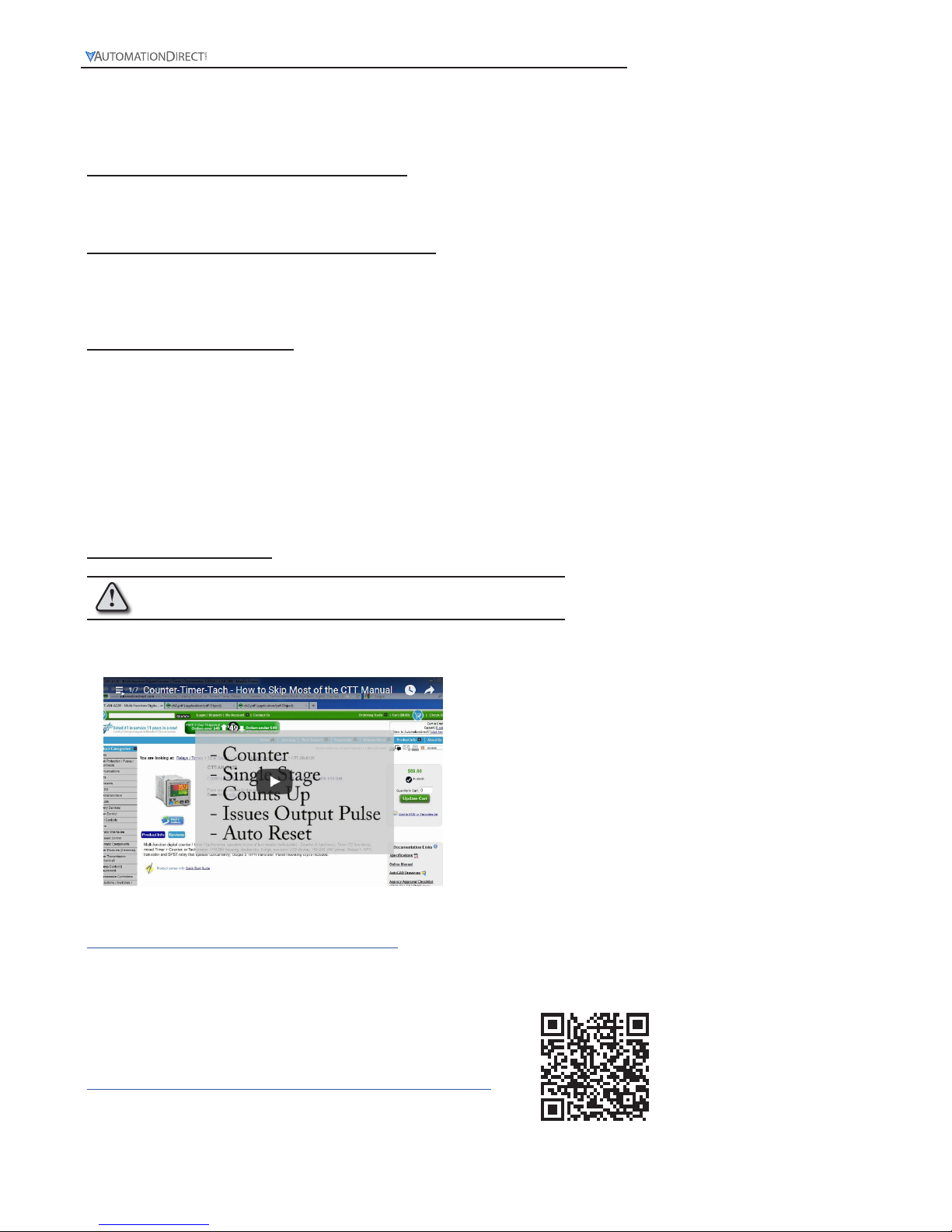
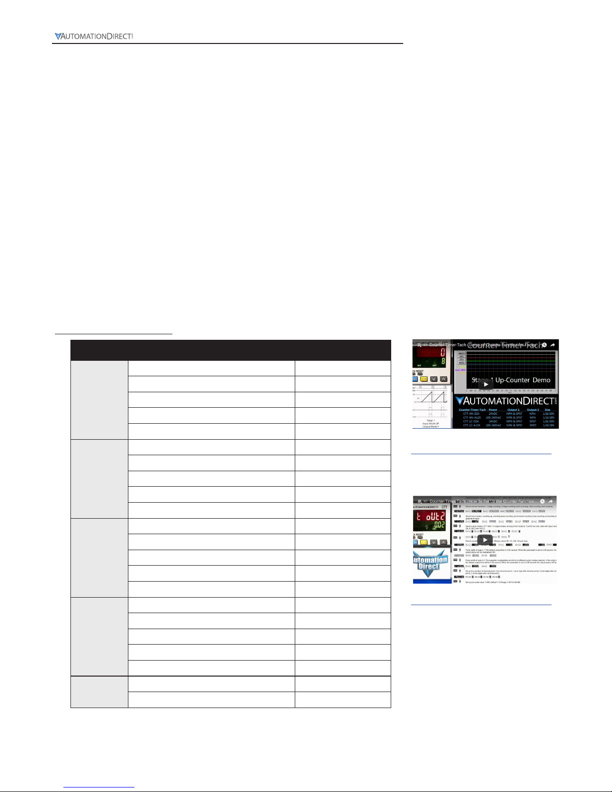
Click on the above thumbnail or go to
https://www.automationdirect.com/VID-RL-0002
for a video on how to skip most of the CTT manual.
For a full set of Demo and Set Up videos for the CTT
units please scan the QR code or follow the link below.
https://www.automationdirect.com/videos/home?t=link&cat1=60
When you see the “exclamation mark” icon in the left-hand margin, the paragraph to
its immediate right will be a warning. This information could prevent injury, loss of
property, or even death (in extreme cases).
1-2
1-800-633-0405
Digital Counter / Timer / Tach User Manual, 1st Ed.
Page 9

General Description
The CTT series is an extremely versatile multi-function device that is easily configured for operation as a digital
counter, timer, combination timer + counter, or tachometer. Both voltage and non-voltage inputs are accepted
from a wide variety of sensor types with NPN, PNP, or dry contact outputs. The first output on the CTT is
a single-pole, single-throw relay and NPN transistor that operate concurrently. The second CTT output can
be ordered as either a single-pole, double throw relay or NPN transistor. Parameters are easily set using the
externally accessible DIP switches or the lockable keypad. The double-line, 6-digit, two-color LCD display
shows the counter, timer, or tachometer present values, setting values and menu parameters during set-up.
Additional individual indicators are provided for inputs, outputs and functions. The standard 1/16 DIN size,
included panel mounting clip and gasket make panel mounting a snap. The CTT is available in 120-240VAC
and 24VDC powered models.
www.automationdirect.com
1-3
Digital Counter / Timer / Tach User Manual, 1st Ed.
Timer Functions (Up or Down)
Signal On Delay 1 Repeat Cycle
Signal On Delay 2 Repeat Cycle Hold
Signal Off Delay Repeat Cycle 2
Signal On Signal Cumulate
Power On Delay Signal Twin On-Start
Power On Delay Hold Signal Twin Off-Start
Tachometer Output Modes
Select from four (4) different output modes
2Lo/1Lo
2Lo/1Hi
2Hi/1Lo
2Hi/1Hi
Counter Functions Counter Input Modes Counter Output Modes
1-Stage Up
Select from eleven (11) different
output modes (F, N, C, R, K, P, Q,
A, S, T, D)
2-Stage Down
Batch Up / Command Down
Total Up/ Down
Dual Quadrature
Addition
Subtraction
Timer + Counter
Timer Functions (Up or
Down)
Counter Input Modes Counter Output Modes
Signal On Delay 1 Up
Select from eight (8) different output modes (F, N, C, R, K, P, Q, A)
Signal On Delay 2 Down
Signal Off Delay
Signal On
Power On Delay
Power On Delay Hold
Repeat Cycle
Repeat Cycle Hold
Click on the above thumbnail or go to
https://www.automationdirect.com/VID-RL-0001
for a short introductory video for the CTT units.
Page 10
1-4
1-800-633-0405
Digital Counter / Timer / Tach User Manual, 1st Ed.
CTT- AN- D24
D24: 24VDC powered
A120: 100-240VAC powere
d
AN: NPN output 2
1C: SPDT relay output 2
Counter/Timer/Tachometer
Model Number Explanation
Features
-Can operate as a digital counter, timer, combination timer + counter or tachometer
-Accepts voltage and non-voltage inputs from a wide variety of NPN, PNP, or dry contact sensors
-Selectable counting speeds from 1 to 10,000 cycles per second
-Multiple transistor and relay outputs can operate as momentary or maintained
-Double-line, 6-digit, 2-color LCD display
-Easy configuration with externally accessible DIP switches or the lockable keypad
-Display decimal point selection
- Available in 120-240VAC and 24VDC powered models
-UL508 listed, CE marked
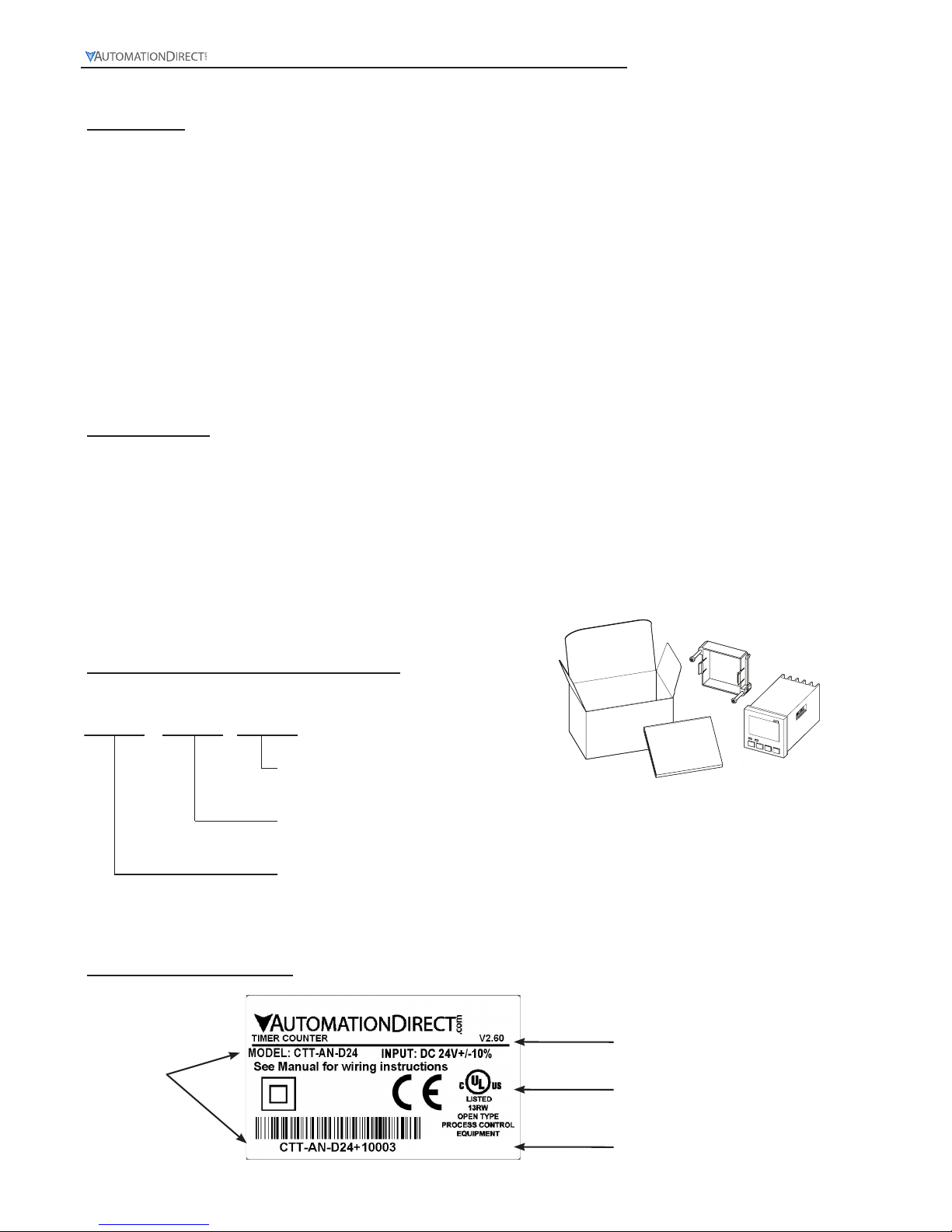
Unpacking
After receiving the CTT Counter/Timer/Tach, please check for the following:
• Make sure that the package includes the CTT Counter/Timer/Tachometer, the mounting bracket and
hardware, and the Quick Start Guide.
• Inspect the unit to insure it was not damaged during shipment.
• Make sure that the part number indicated on the label corresponds with the part number of your order.
CTT-AN-D24
Model Number
Input Specification
Agency Approvals
Country of Origin
Label Information
MADE IN CHINA
Page 11
Digital Counter / Timer / Tach User Manual, 1st Ed.
1-5
www.automationdirect.com
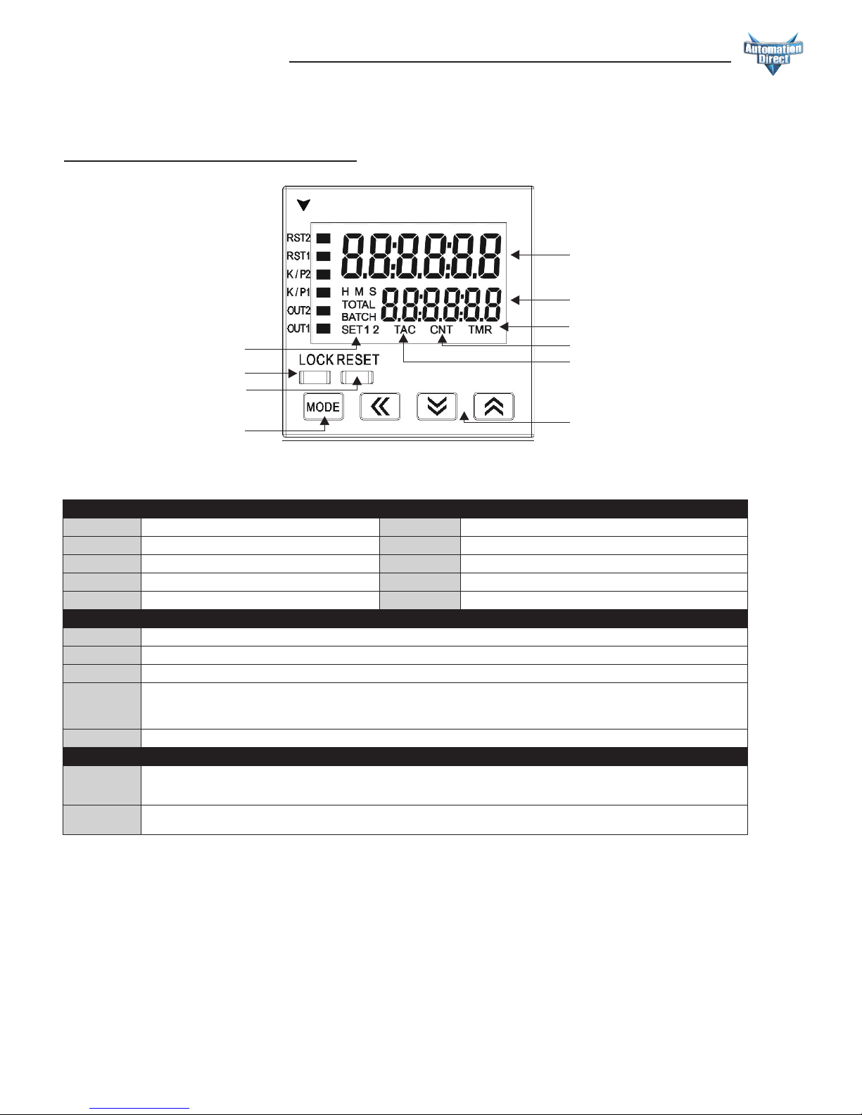
LCD Display and Indicators
RST 1/2
Light on when reset signal is detected
BATCH
“Batch Counting Mode” in Counter
K/P 1/2
Light on when key-protected mode is enabled
SET 1 2
SV1, SV2 display
OUT 1/2
Light on when output is executing
TAC
Light on in Tachometer function
H M S
Hour, minute, second, unit of timer, displayed in Timer function
CNT
Light on in Counter function
TOTAL
“Total Counting Mode” in Counter function
TMR
Light on in Timer function
Key Operation
, .
Increase and decrease SV or change paramter settings
´
Left move 1 digit of the selected digit. The indicator of the selected digit will flash.
Ä
Save the set parameters or switch among functions.
LOCK
Prevent settings from being changed. Key-protected mode still works after the power is switched off. Press LOCK to enter key-protected mode. In non-key-protected
status, press LOCK to enter Lock 1, press LOCK again to enter Lock 2. Press
Ä
and ´ at the same time to disable key-protected mode.
LoC1
(Lock 1) disables
the functions of all keys.
LoC2
(Lock 2) allows users to change SV and functions of RESET remain. LOCK only functions in non-key-protected status.
RESET Clear and reset PV.
Modes: Operation Mode and Configuration Mode
Operation
When the power is on, the timer/counter/tachometer is in the operation mode. Press ,. to change SV, or ´ to select digit to change. The indicator of the
selected digit will flash. After the change is made, press Ä to save the setting. If SV or paramters are not changed, press Ä once to switch between SET1 and
SET2.
Configuration
Press Ä in operation mode for more than 3 seconds to enter configuration mode. Press Ä once to switch among parameters. To return to operation mode, press
Ä for more than 3 seconds.
Reset 2 indicator
Reset 1 indicator
Key protect 2 indicator
Output 2 indicator
Key protect 1 indicator
Output 1 indicator
Special function indicator
Lock key
Reset key
Mo
de and number shift key
PV(Present Value) display
SV(Set Value) display
Timer function indicator
Counter function indicator
Tachometer function indi cator
Up/Down key
CTT
A
UTOMATION
D
IRECT
.com
Display, Indicators and Keys
Page 12
Digital Counter / Timer / Tach User Manual, 1st Ed.
1-800-633-0405
1-6
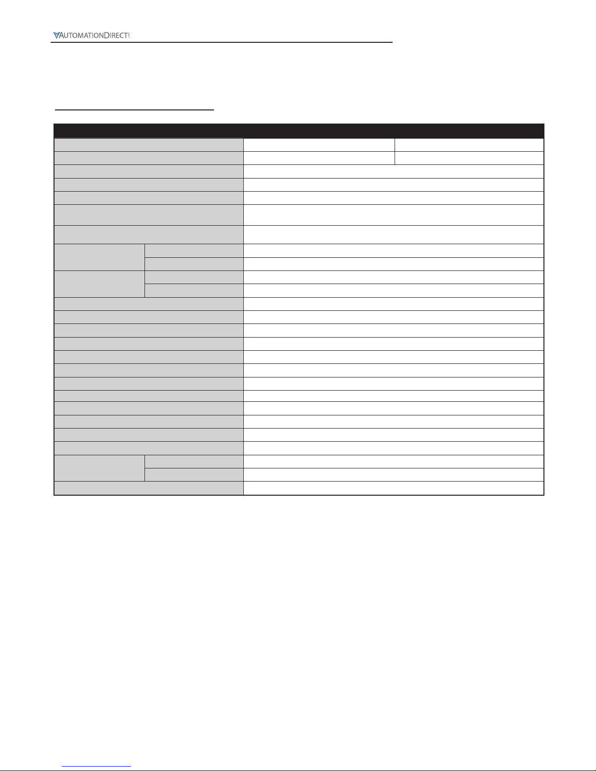
General Specifications
Digital Counter / Timer / Tachometer General Specifications
Input Power Requirements
100 to 240 VAC 50/60 Hz 24 VDC
Operation Voltage Range
85 to 264 VAC 21.6 to 26.4 VDC
Power Consumption
Less than 10VA
Power Source
12VDC w10%, 100mA
Display
Double-line, 6-digit LCD display (SV = 8mm, PV = 6mm)
Input Signal
NPN ON impedance 1K ohm max. ON residual voltage: 2V max.
PNP 4.5 to 30VDC, low level: 0 to 2VDC
Output 1
Relay: SPST max. 250VAC, 5A (resistive load), 4A (inductive load); Transistor: NPN open collector. When 100mA @
30VDC, residual voltage = 1.5VDC max
Output 2
CTT-1C-xxx
Relay: SPDT max. 250VAC, 5A (resistive load), 4A (inductive load)
CTT-AN-xxx
Transistor: NPN open collector. When 100mA @ 30VDC residual voltage = 1.5VDC max
Life Expectancy
Mechanical
10,000,000 operations (frequency 18,000 operations/hr)
Electrical
100,000 operations (frequency 900 operations/hr)
Output Duration (where used)
0.00 (latching) / 0.01 to 99.99 seconds
Output Switching Time
2 milliseconds max
Dielectric Strength
2000VAC 50/60Hz for 1 minute
Vibration Resistance
Without damage: 10 ~ 55Hz, amplitude = 0.75mm, 3 axes for 2 hours
Shock Resistance
Without damage: drop 4 times, 300m/s² 3 edges, 6 surfaces and 1 corner
Ambient Temperature
+32°F to +122°F (0°C to +50°C)
Storage Temperature
-4°F to +149°F (-20°C to +65°C)
Altitude
2000m or less
IP Rating
IP 66 (with proper enclosure installation)
Case Materials
Case = ABS Plastic, Lens = Polycarbonate
Ambient Humidity
35% to 85% RH (non-condensing)
Memory Backup upon Power Failure
EEPROM writing up to 100,000 times; Memory duration: 10 years
Terminals
Conforming Wiring
0.25-1.65mm² (24 to 16 AWG)
Permitted Torque
0.5Nm (0.369 ft/lbs)
Agency Approvals
UL508 listed (E311366), cULus, CE marked
Page 13
Digital Counter / Timer / Tach User Manual, 1st Ed.
1-7
www.automationdirect.com
MODE
45.00
[1.77]
45.00
[1.77]
65.00
[2.56]
60.00
[2.36]
1
6
11
2
7
12
3
8
13
4
9
14
5
10
15
44.80
[1.76]
44.80
[1.76]
6.35
[0.25]
44.80
[1.76]
CTT
AUTOMATIONDIRECT
.com
RST2
RST1
K/P2
K/P1
OUT2
OUT1
LOCK RESET
44.80
[1.76]
79.35
[3.12]
6.35
[0.25]
47.85
[1.88]
47.85
[1.88]
79.35
[3.12]
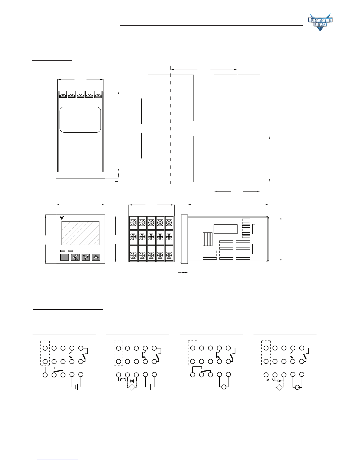
Drawings
mm [inches]
0V CP1
CP2/
GATE
+12V RST1
RST2/
START
0V CP1
CP2/
GATE
+12V RST1
RST2/
START
N.O.
COM
LOAD +V0V
N.C.
N.O.
COM
CTT-1C-D24
OUT
2
21.6 to
26.4 VDC
Load
21.6 to
26.4 VDC
OUT
1
OUT
2
CTT-AN-D24
N.O.
COM
0V
LOAD
OUT
1
0V
LOAD
0V CP1
CP2/
GATE
+12V RST1
RST2/
START
0V CP1
CP2/
GATE
+12V RST1
RST2/
START
N.O.
COM
LOAD +V0V
CTT-1C-A120
OUT
2
AC100 to 240V
50/60Hz
Load
AC100 to 240V
50/60Hz
OUT
1
OUT
2
CTT-AN-A120
N.O.
COM
0V
LOAD
OUT
1
0V
LOAD
N.O.
COM
POWER SOURCE
12VDC @ 100mA
POWER SOURCE
12VDC @ 100mA
POWER SOURCE
12VDC @ 100mA
POWER SOURCE
12VDC @ 100mA
N.C.
109
321
1514
876
131211
54
10
9
321
15
14
876
13
1211
54
10
9
1514
876
131211
54
10
9
321
15
14
876
131211
54
321
+
-
+
-
S
S
Terminal Layout
Page 14

In This Chapter...
Display, Indicators and Keys ...........................................2-2
Getting Started .....................................................2-3
Counter Functions ...................................................2-5
1-Stage Counting Up ................................................2-5
1-Stage Counting Down .............................................2-9
1-Stage Counting UP/Command Counting Down (UdA) ....................2-13
1-Stage Counting UP/Counting Down (UdB) .............................2-18
1-Stage Counting Quadrature (UdC) ...................................2-23
2-Stage Counting UP ...............................................2-28
2-Stage Counting Down ............................................2-33
2-Stage Counting UP/Command Counting Down (UdA) ....................2-38
2-Stage Counting UP/Counting Down (UdB) .............................2-45
2-Stage Counting Quadrature (UdC) ...................................2-52
Batch Counting UP .................................................2-59
Batch Counting Down ..............................................2-64
Batch Counting UP/Command Counting Down (UdA). . . . . . . . . . . . . . . . . . . . . . 2-69
Batch Counting UP/Counting Down (UdB) ..............................2-75
Batch Counting Quadrature (UdC) .....................................2-81
Total Counting UP .................................................2-87
Total Counting Down ..............................................2-92
Total Counting UP/Command Counting Down (UdA) ......................2-97
Total Counting UP/Counting Down (UdB) ..............................2-103
Total Counting Quadrature (UdC) ....................................2-109
Dual Counting Addition ............................................2-115
Dual Counting Subtraction ..........................................2-120
CoUnTer
Chapter
Chapter
Chapter
2
2
2
www.automationdirect.com
2-1
Digital Counter / Timer / Tach User Manual, 1st Ed.
Page 15
Digital Counter / Timer / Tach User Manual, 1st Ed.
1-800-633-0405
2-2
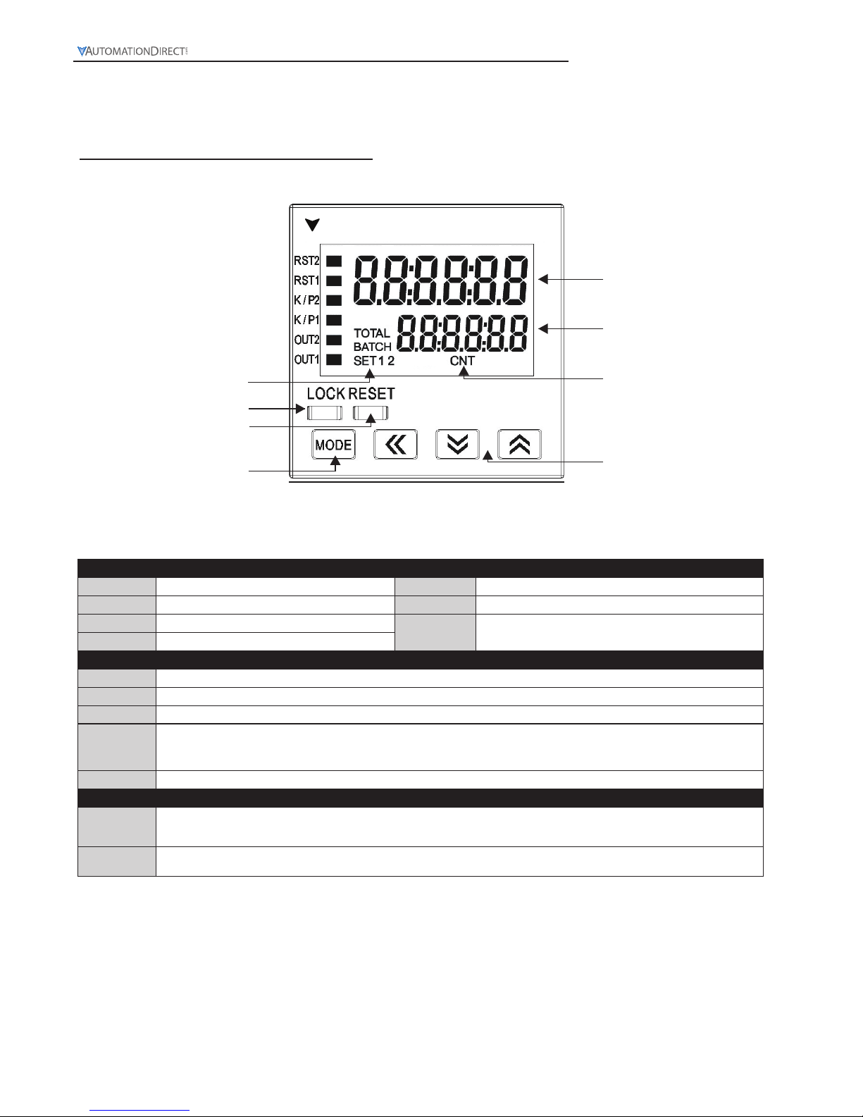
Reset 2 indicator
Reset 1 indicator
Key protect 2 indicator
Output 2 indicator
Key protect 1 indicator
Output 1 indicator
Special function indicator
Lock key
Reset key
Mo
de and number shift key
PV(Present Value) display
SV(Set Value) display
Counter function indicator
Up/Down key
CTT
A
UTOMATION
D
IRECT
.com
Display, Indicators and Keys
LCD Display and Indicators
RST 1/2
Light on when reset signal is detected
BATCH
“Batch Counting Mode” in Counter
K/P 1/2
Light on when key-protected mode is enabled
SET 1 2
SV1, SV2 display
OUT 1/2
Light on when output is executing
CNT
Light on in Counter function
TOTAL
“Total Counting Mode” in Counter function
Key Operation
, .
Increase and decrease SV or change paramter settings
´
Left move 1 digit of the selected digit. The indicator of the selected digit will flash.
Ä
Save the set parameters or switch among functions.
LOCK
Prevent settings from being changed. Key-protected mode still works after the power is switched off. Press LOCK to enter key-protected mode. In non-key-protected
status, press LOCK to enter Lock 1, press LOCK again to enter Lock 2. Press
Ä
and ´ at the same time to disable key-protected mode.
LoC1
(Lock 1) disables
the functions of all keys.
LoC2
(Lock 2) allows users to change SV and functions of RESET remain. LOCK only functions in non-key-protected status.
RESET
Clear and reset PV.
Modes: Operation Mode and Configuration Mode
Operation
When the power is on, the timer/counter/tachometer is in the operation mode. Press ,. to change SV, or ´ to select digit to change. The indicator of the
selected digit will flash. After the change is made, press Ä to save the setting. If SV or paramters are not changed, press Ä once to switch between SET1 and
SET2.
Configuration
Press Ä in operation mode for more than 3 seconds to enter configuration mode. Press Ä once to switch among parameters. To return to operation mode, press
Ä for more than 3 seconds.
Page 16

Digital Counter / Timer / Tach User Manual, 1st Ed.
2-3
www.automationdirect.com
Getting Started with Counters
Step 1: Determine Required Counter Function
Counter Functions
1-Stage Counting (
StA6E 1
)
A single count setting value SV is available in 1-Stage Counting. Both Outputs 1 and 2 operate concurrently and will
turn ON momentarily or will be maintained ON depending on the Output Mode selected.
2-Stage Counting (
StA6E 2
)
In 2-Stage Counting, count setting value SV1 controls Output 1 and count setting value SV2 controls Output 2.
Outputs will turn ON momentarily or will be maintained ON depending on the output mode selected.
Batch Counting (
bAtCH
)
In Batch Counting, count setting value SV controls Output 2 which will turn ON momentarily or will be maintained ON depending on the output mode selected. Count setting value BATCH SV controls Output 1which will
be maintained ON.
Total Counting (
totAL
)
A single count setting value SV is available in Total Counting. Both Outputs 1 and 2 operate concurrently and will
turn ON momentarily or will be maintained ON depending on the Output Mode selected.
Dual Counting (
dUAL
)
A single count setting value SV is available in Dual Counting. Both Outputs 1 and 2 operate concurrently and will
turn ON momentarily or will be maintained ON depending on the Output Mode selected.
Step 2: Determine Required Counter Input Mode
Counter Input Modes:
Counting Up (UP)*
With the input signal OFF at input CP2, each leading edge of the input signal at CP1 will increment the count
present value PV by 1. Turning ON the input signal at CP2, will prohibit the input signal at CP1 from incrementing
the PV.
With the input signal ON at input CP1, each trailing edge of the input signal at CP2 will increment the count
present value PV by 1. Turning OFF the input signal at CP1, will prohibit the input signal at CP2 from incrementing the PV.
Counting Down (
down
)*
With the input signal OFF at input CP2, each leading edge of the input signal at CP1 will decrement the count
present value PV by 1. Turning ON the input signal at CP2, will prohibit the input signal at CP1 from decrementing
the PV.
With the input signal ON at input CP1, each trailing edge of the input signal at CP2 will decrement the count
present value PV by 1. Turning OFF the input signal at CP1, will prohibit the input signal at CP2 from decrementing the PV.
Counting Up / Command Counting Down (
Ud A
)*
With the input signal OFF at input CP2, each leading edge of the input signal at CP1 will increment the count
present value PV by 1.
With the input signal ON at input CP2, each leading edge of the input signal at CP1 will decrement the count
present value PV by 1.
Counting Up / Counting Down (
Ud b
)*
Each leading edge of the input signal at CP1 will increment the count present value PV by 1.
Each leading edge of the input signal at CP2 will decrement the count present value PV by 1.
Page 17
Digital Counter / Timer / Tach User Manual, 1st Ed.
1-800-633-0405
2-4
Quadrature (
Ud C
)*
When the quadrature input signal at CP1 changes before the input signal at CP2, the trailing edge of CP2 will increment the count present value PV by 1.
When the quadrature input signal at CP2 changes before the input signal at CP1, the leading edge of CP2 will decrement the count present value PV by 1.
Addition (
Add
)**
Each leading edge of the input signal at CP1 will increment the count present value PV by 1.
Each leading edge of the input signal at CP2 will increment the count present value PV by 1.
Subtraction (
SUb
)**
Each leading edge of the input signal at CP1 will increment the count present value PV by 1.
Each leading edge of the input signal at CP2 will decrement the count present value PV by 1.
*Available only with counter functions 1-stage, 2-stage, batch, total
**Available only with counter function dual
Step 3: Determine the Counter Output Mode by Visiting the Page Numbers Shown for Your Desired
Counter Function and Input Mode
Counter Output Modes:
Counter
Function
Counter Input Mode Page Number
1-Stage
Counting Up (UP)
2-5
Counting Down (
DOWN
)
2-9
Counting UP/Command Counting Down (
UdA
)
2-13
Counting UP/Counting Down (
UdB
)
2-18
Counting Quadrature (
UdC
)
2-23
2-Stage
Counting Up (UP)
2-28
Counting Down (
DOWN
)
2-33
Counting UP/Command Counting Down (
UdA
)
2-38
Counting UP/Counting Down (
UdB
)
2-45
Counting Quadrature (
UdC
)
2-52
Batch
Counting Up (UP)
2-59
Counting Down (
DOWN
)
2-64
Counting UP/Command Counting Down (
UdA
)
2-69
Counting UP/Counting Down (
UdB
)
2-75
Counting Quadrature (
UdC
)
2-81
Total
Counting Up (UP)
2-87
Counting Down (
DOWN
)
2-92
Counting UP/Command Counting Down (
UdA
)
2-97
Counting UP/Counting Down (
UdB
)
2-103
Counting Quadrature (
UdC
)
2-109
Dual
Addition (
Add
)
2-115
Subtraction (
SUB
)
2-120
Click on the above thumbnail or go to
https://www.automationdirect.com/VID-RL-0004
for a short Counter demo video.
Click on the above thumbnail or go to
https://www.automationdirect.com/VID-RL-0003
for a Counter Set-up video.
Page 18
Digital Counter / Timer / Tach User Manual, 1st Ed.
2-5
www.automationdirect.com
1-Stage Counting (
StA6E 1
)
A single count setting value SV is available in 1-Stage Counting. Both Outputs 1 and 2 operate concurrently and
will turn ON momentarily for the time set in the output pulse width parameter (
tout2
) or will be maintained ON
depending on the Output Mode selected.
CTT Counter Functions
1-Stage Counting (StA6E 1)
Counting Up (UP)
Counting Up (UP)
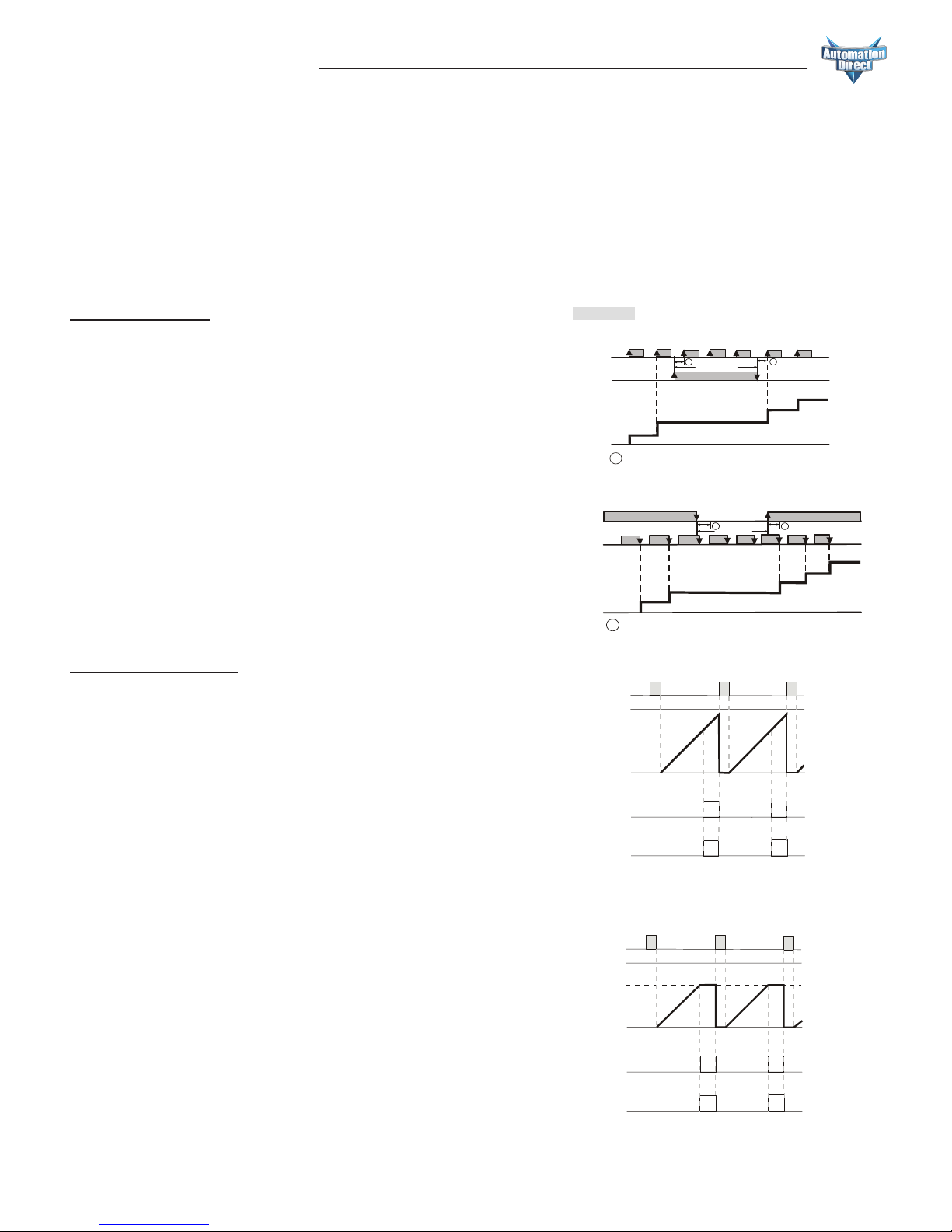
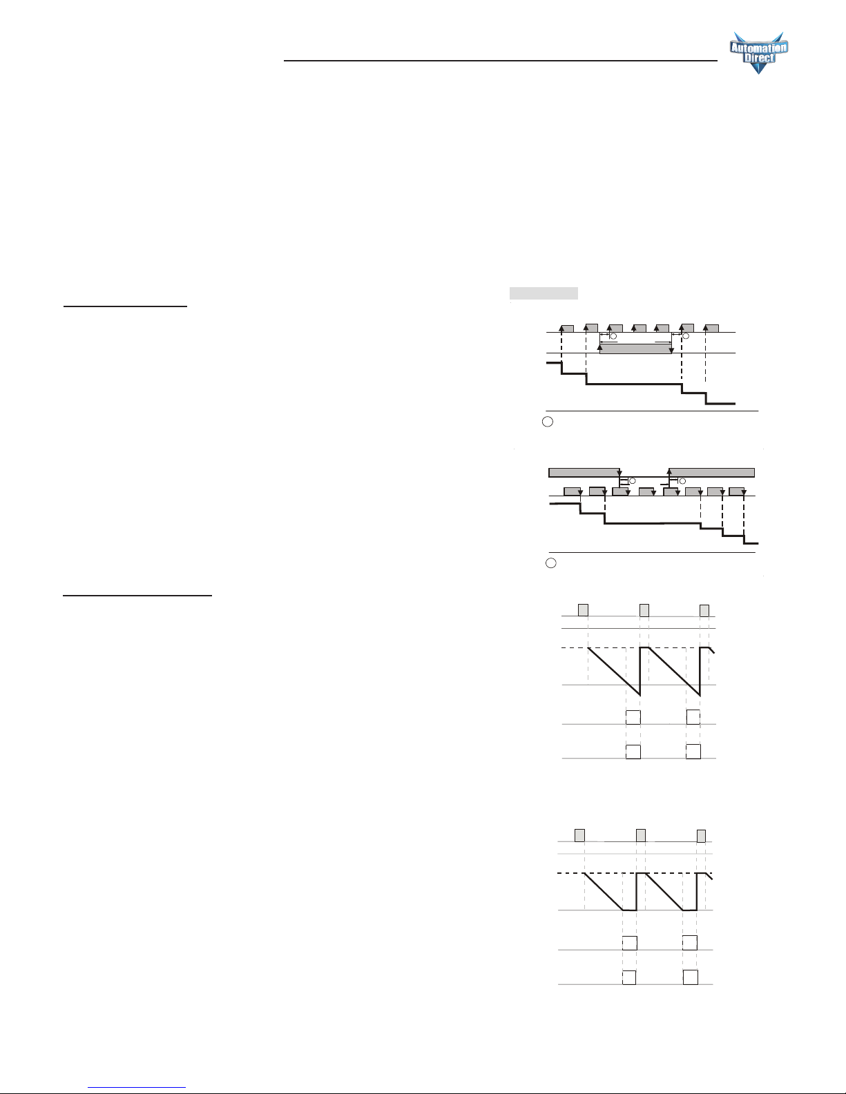
With the input signal OFF at input CP2, each leading edge of the
input signal at CP1 will increment the count present value PV by 1.
Turning ON the input signal at CP2, will prohibit the input signal
at CP1 from incrementing the PV.
Input Mode:
Mode F (F)
When the count present value PV counts up to the count setting
value SV, both outputs 1 and 2 will turn ON. The count PV
will continue to increment with each input signal.
The leading edge of a “reset” input signal at RST1 will turn
OFF both outputs, reset the count PV to 0, and prohibit an
input signal from incrementing the count PV. The trailing edge
of the “reset” signal at RST1 enables counting to begin.
The “reset” signal minimum pulse width is set by reset pulse
width parameter (
rtSr
) or DIP Switch 8.
Output Modes:
Mode N (n)
When the count present value PV counts up to the count
setting value SV, both outputs 1 and 2 will turn ON. The count
PV will remain at the count SV regardless of additional input
signals.
The leading edge of a “reset” input signal at RST1 will turn
OFF both outputs, reset the count PV to 0, and prohibit an
input signal from incrementing the count PV. The trailing edge
of the “reset” signal at RST1 enables counting to begin.
The “reset” signal minimum pulse width is set by reset pulse
width parameter (
rtSr
) or DIP Switch 8.
Prohibit
A
A
0
1
2
3
4
5
H
L
H
L
0
CP
1
CP
2
Present
Value
CP1: Counter input prohibited CP2: Counter input
Note: has to be larger than width of min. Input signal
A
Counting up
Prohibit
A
A
0
1
2
3
4
H
L
H
L
0
CP1
CP2
Present
Value
CP1: Counter input CP2: C ounter input prohibited
Note: has to be larger than width of min. Input signal
A
With the input signal ON at input CP1, each trailing edge of the
input signal at CP2 will increment the count present value PV by 1.
Turning OFF the input signal at CP1, will prohibit the input signal
at CP2 from incrementing the PV.
999999
RESET
SV
OUT2
OUT1
PV
Stage 1
Input Mode UP
Output Mode F
0
RESET
999999
SV
PV
OUT2
OUT1
Stage 1
Input Mode UP
Output Mode N
0
Page 19
Digital Counter / Timer / Tach User Manual, 1st Ed.
1-800-633-0405
2-6
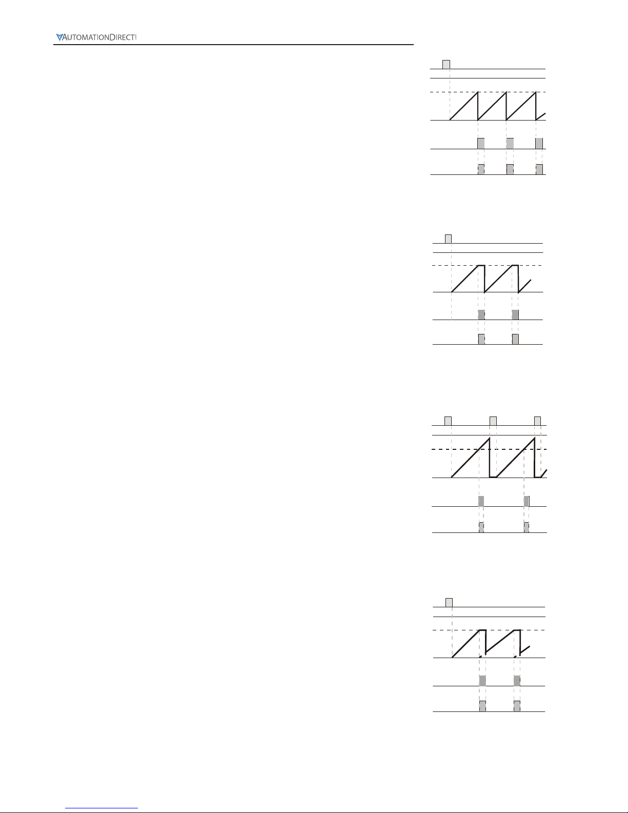
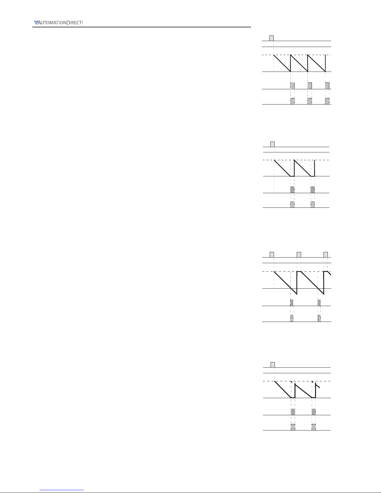
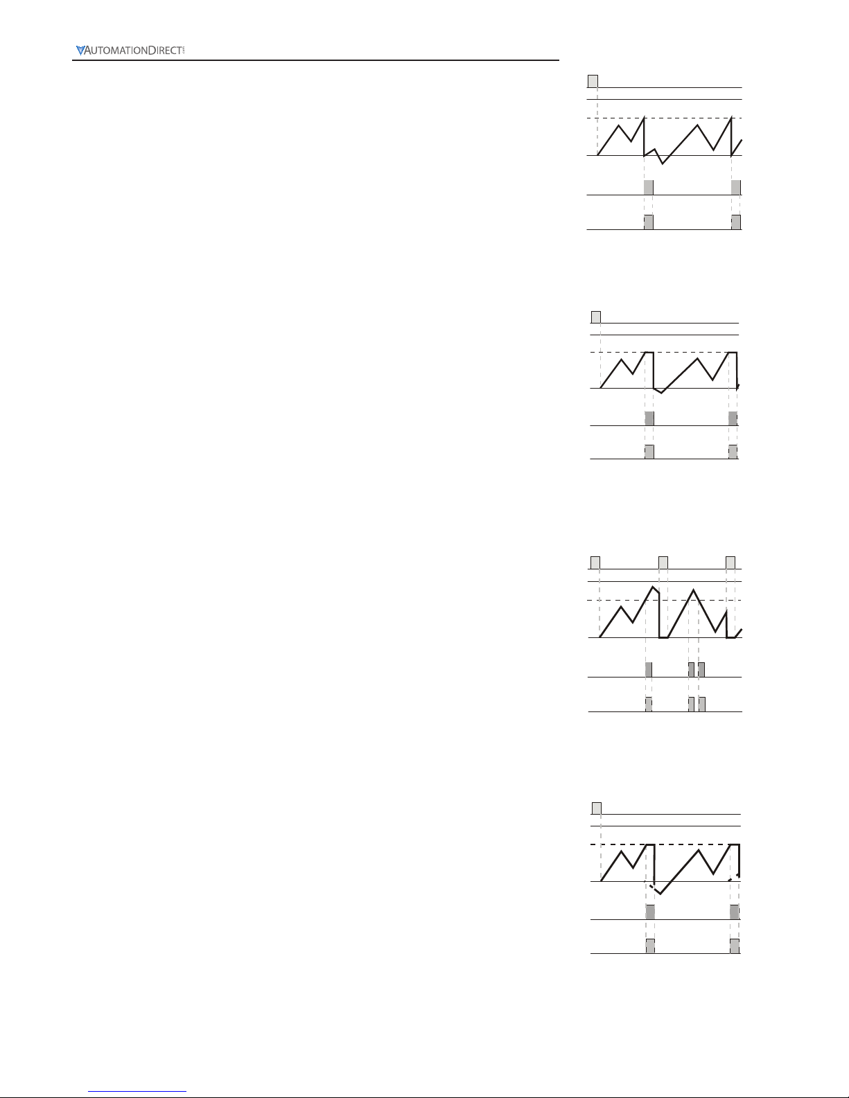
Mode C (C)
When the count present value PV counts up to the count setting
value SV, both outputs 1 and 2 will turn ON momentarily for the
time set in the output pulse width parameter (
tout2
) and the
count PV will reset automatically to 0.
The leading edge of a “reset” input signal at RST1 will turn both
outputs OFF, reset the count PV to 0 and prohibit an input signal
from incrementing the count PV. The trailing edge of the “reset”
signal at RST1 enables counting to begin.
The “reset” signal minimum pulse width is set by reset pulse width
parameter (
rtSr
) or DIP Switch 8.
Mode R (r)
When the count present value PV counts up to the count setting
value SV, both outputs 1 and 2 will turn ON momentarily for the
time set in the output pulse width parameter (
tout2
).
The count PV is prohibited from incrementing until the end of the
output pulse time (
tout2
) when the outputs turn OFF and the
count PV is reset automatically to 0. The leading edge of a “reset”
input signal at RST1 will turn OFF both outputs, reset the count
PV to 0 and prohibit an input signal from incrementing the count
PV.
The trailing edge of the “reset” signal at RST1 enables counting to
begin. The “reset” signal minimum pulse width is set by reset pulse
width parameter (
rtSr
) or DIP Switch 8.
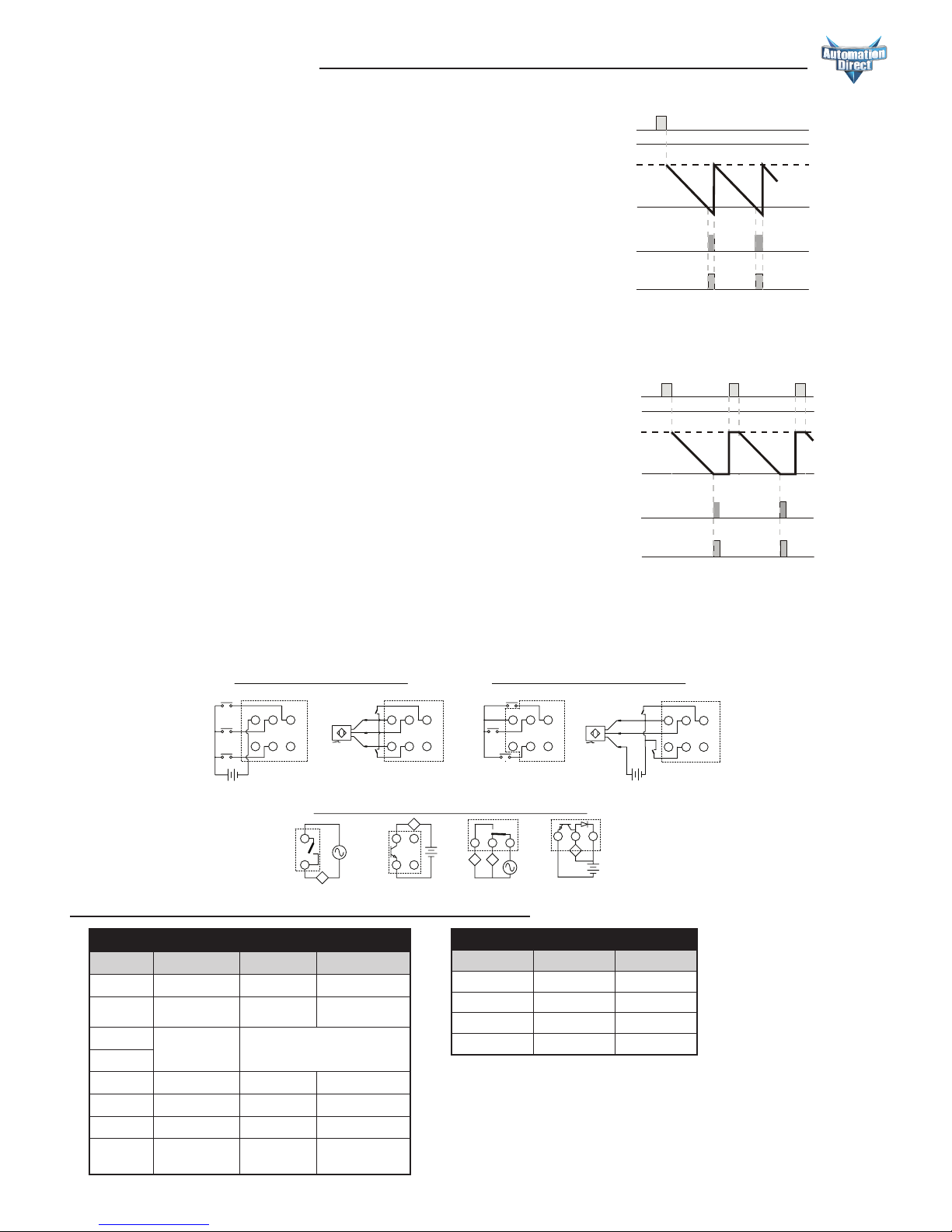
Mode K (k)
When the count present value PV counts up to the count setting
value SV, both outputs 1 and 2 will turn ON momentarily for the
time set in the output pulse width parameter (
tout2
). The count
PV will continue to increment with each input signal.
The leading edge of a “reset” input signal at RST1 will turn OFF
both outputs, reset the count PV to 0 and prohibit an input signal
from incrementing the count PV. The trailing edge of the “reset”
signal at RST1 enables counting to begin.
The “reset” signal minimum pulse width is set by reset pulse width
parameter (
rtSr
) or DIP Switch 8.
Mode P (P)
When the count present value PV counts up to the count setting
value SV, both outputs 1 and 2 will turn ON momentarily for the
time set in the output pulse width parameter (
tout2
). The count
PV display is prohibited from incrementing until the end of the
output pulse time, when both outputs turn OFF and the count
PV is reset automatically to 0 and any input signals that occurred
during the output pulse time.
The leading edge of a “reset” input signal at RST1 will turn OFF
both outputs, reset the count PV to 0 and prohibit an input signal
from incrementing the count PV.
The trailing edge of the “reset” signal at RST1 enables counting to
begin. The “reset” signal minimum pulse width is set by reset pulse
width parameter (
rtSr
) or DIP Switch 8.
RESET
999999
SV
PV
OUT2
OUT1
TTT
Stage 1
Input Mode UP
Output Mode C
TTT
0
RESET
999999
SV
PV
OUT2
OUT1
T
T
Stage 1
Input Mode UP
Output Mode R
TT
0
RESET
999999
SV
PV
OUT2
OUT1
T
T
T
T
Stage 1
Input Mode UP
Output Mode K
0
RESET
999999
SV
PV
OUT2
OUT1
TT
Stage 1
Input Mode UP
Output Mode P
TT
0
Page 20

Digital Counter / Timer / Tach User Manual, 1st Ed.
2-7
www.automationdirect.com
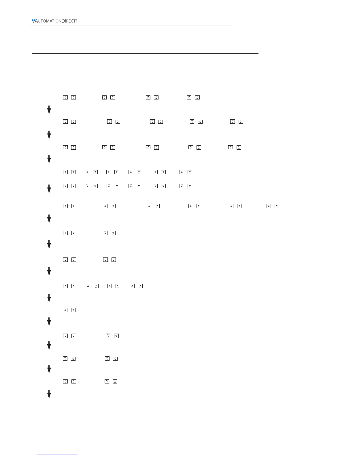
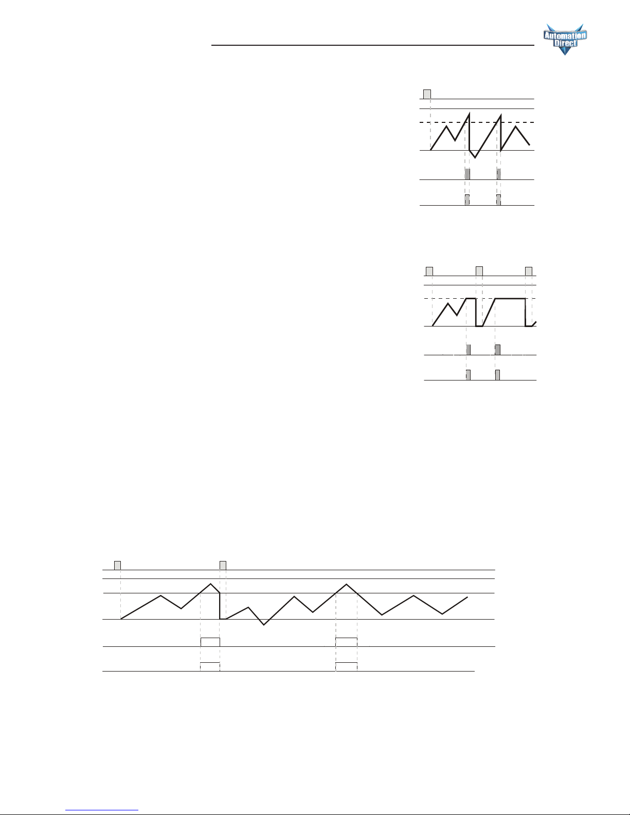
Mode Q (q)
When the count present value PV counts up to the count setting
value SV, both outputs 1 and 2 will turn ON momentarily for the
time set in the output pulse width parameter (
tout2
). The count
PV will continue to increment with each input signal until the end
of the output pulse time, when the outputs turn OFF and the count
PV is reset automatically to 0.
The leading edge of a “reset” input signal at RST1 will turn OFF
both outputs, reset the count PV to 0 and prohibit an input signal
from incrementing the count PV. The trailing edge of the “reset”
signal at RST1 enables counting to begin.
The “reset” signal minimum pulse width is set by reset pulse width
parameter (
rtSr
) or DIP Switch 8.
Mode A (A)
When the count present value PV counts up to the count setting
value SV, both outputs 1 and 2 will turn ON momentarily for
the time set in the output pulse width parameter (
tout2
). The
count PV will remain at the count SV regardless of additional input
signals.
The leading edge of a “reset” input signal at RST1 will turn OFF
both outputs, reset the count PV to 0 and prohibit an input signal
from incrementing the count PV. The trailing edge of the “reset”
signal at RST1 enables counting to begin.
The “reset” signal minimum pulse width is set by reset pulse width
parameter (
rtSr
) or DIP Switch 8.
Output Mode - Table 2
Switch 3 Switch 4 Output Mode
OFF OFF
F
ON OFF
N
OFF ON
C
ON ON
R
Dip Switch Settings - Table 1
Switch Function Off On
1 Dip switch Disabled Enabled
2 Counting mode Counting up Counting down
3
Output mode See Output Mode Table - Table 2
4
5 Counting speed 30cps 10Kps
6 Reserved - -
7 Input signal NPN PNP
8
Reset signal
pulse width
20 ms 1 ms
Outputs
Load
Load
OUT1
NPN/
SINKING
OUT2
SPDT
Load
OUT1
SPST
0V CP1
CP2/
GATE (Pause)
+12V RST1
RST2/
START
CP2
Input
CP1
Input
Reset
0V CP1
+12V RST1
RST2/
START
Reset
0V CP1
+12V RST1
RST2/
START
Reset
PNP
INPUTS
L-
Load
OUT2
NPN/
SINKING
Load
0V CP1
+12V RST1
RST2/
START
Reset
L-
L+
NPN
INPUTS
CP1
Input
CP2
Input
CP2
Input
CP1
Input
CP1
Input
CP2
Input
L+
+VDC 0VDC
Externally Powered
Internally Powered
+VDC 0VDC
Externally Powered
Internally Powered
(Optional)
(Optional)
(Optional)
(Optional)
+VDC
0VDC
+VDC
0VDC
10
9
321
15
14
10
15
876
1312
11
876
131211
876
131211
321
876
131211
Counter Wiring Examples
CP2/
GATE (Pause)
CP2/
GATE (Pause)
CP2/
GATE (Pause)
RESET
999999
SV
PV
OUT2
OUT1
TT
TT
Stage 1
Input Mode UP
Output Mode Q
0
RESET
999999
SV
PV
OUT2
OUT1
TT
TT
Stage 1
Input Mode UP
Output Mode A
0
DIP Switch Set Up of the CTT Parameters:
Page 21
Digital Counter / Timer / Tach User Manual, 1st Ed.
1-800-633-0405
2-8
Keypad set up of the parameters for 1-Stage Counting:
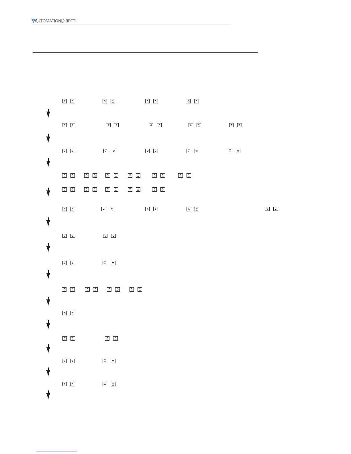
Select functions: There are 4 modes in CTT, (left to right) timer, counter, tachometer and timer + counter.
–FunC Cont taCh –mixtime
Select counter functions: 1-stage counting, 2-stage counting, batch counting, total counting, dual counting.
Ä
CntFun sta6e1 sta6e2 batCh total dual
C–inPt
––UP down ud–a ud–b ud–C
Select input modes: counting up, counting down,counting up/command counting down,counting up/counting down,
quadrature input.
C–otmd
FnCr kp
q
a
s
t
d
Select output modes: CTT offer 11 output modes, among which mode S, T and D are only valid with input modes
Ud_A, Ud_b and Ud_C.
Select counting speed: Maximum 10Kcps; others 5K, 1K, 200, 30 and 1cps.
C–Sped –10k ––5k ––1k –200 ––30
t–out1
Pulse width of output 1: The default output time is 0.02 second. When the parameter is set to 0.00 second, the
output status will be maintained ON. Range = 0.00 to 99.99 seconds.
–––1
–002 –000
t–out2
Pulse width of output 2: This paramter is adjustable according to different output modes selected. If the output mode is C,
the default output time will be 0.02 second. Range = 0.01 to 99.99 seconds.
–002 –000
–point
Set up the position of decimal point: 0 (no decimal point), 1 (one digit after decimal point), 2 (two digits after decimal
point), 3 (three digits after decimal point).
0123
psCale 1000
Set up pre-scale value: 1.000 (default 1:1) Range: 0.001 to 99.999
–pwers
Save the data while switching off the power: When SAVE is selected, the PV will be saved; when CLEAR is selected,
the PV will not be saved.
Clear save
–rtsr
Set up minimum width of reset signal: Default = 20ms; 1ms is also selectable
––20 –––1
inptlC
Select input signal types: NPN and PNP
–npn –pnp
Back to
Top
Ä
Ä
Ä
Ä
Ä
Ä
Ä
Ä
Ä
Ä
or
or
or
or
or
or
or
or or
or
or
or
or or or
or
or
or
or
or or or
or
or or
or
or
or
or or
or
or or
or
or
or or or
or
or or
or or
or or
Ä
To enter the page for parameter setting of the counter, press Ä for the main menu for more than 3 seconds.
After the setup is completed, press Ä for more than 3 seconds under any of the parameter page you are in and
return to the main menu.
Used to convert the displayed PV into engineering unit, such as RPM, inches, millimeters, feet per minute etc. See Tachometer Examples in Chapter 6
Page 22
Digital Counter / Timer / Tach User Manual, 1st Ed.
2-9
www.automationdirect.com
1-Stage Counting (StA6E 1)
A single count setting value SV is available in 1-Stage Counting. Both Outputs 1 and 2 operate concurrently and
will turn ON momentarily for the time set in the output pulse width parameter (tout2) or will be maintained ON
depending on the Output Mode selected.
CTT Counter Functions
1-Stage Counting (StA6E 1)
Counting Down (down)
Counting Down (
down
)
With the input signal OFF at input CP2, each leading edge of the
input signal at CP1 will decrement the count present value PV by 1.
Turning ON the input signal at CP2, will prohibit the input signal
at CP1 from decrementing the PV.
Input Mode:
Mode F (F)
When the count present value PV counts down to 0 both
outputs 1 and 2 will turn ON. The count PV will continue to
decrement with each input signal.
The leading edge of a “reset” input signal at RST1 will turn
OFF both outputs, reset the count PV to the count setting
value SV, and prohibit an input signal from decrementing
the count PV. The trailing edge of the “reset” signal at RST1
enables counting to begin.
The “reset” signal minimum pulse width is set by reset pulse
width parameter (
rtSr
) or DIP Switch 8.
Output Modes:
Mode N (
n)
When the count present value PV counts down to 0 both
outputs 1 and 2 will turn ON. The count PV will remain at 0
regardless of additional input signals.
The leading edge of a “reset” input signal at RST1 will turn
OFF both outputs, reset the count PV to the count setting
value SV, and prohibit an input signal from decrementing
the count PV. The trailing edge of the “reset” signal at RST1
enables counting to begin.
The “reset” signal minimum pulse width is set by reset pulse
width parameter (
rtSr
) or DIP Switch 8.
A
Prohibit
A
n
n-1
n-2
n-3
n-4
n-5
H
L
H
L
CP1
CP2
0
Present
Value
CP1: Counter input prohibited CP2: Counter input
Note: has to be larger than width of min. Input signal
A
Counting down
Prohibit
A
A
n
n-2
n-1
n-4
n-3
H
L
CP1
CP2
Present
Value
0
H
L
CP1: Counter input CP2: Counter input prohibited
Note: has to be l arger than width of min. Input signal
A
With the input signal ON at input CP1, each trailing edge of the
input signal at CP2 will decrement the count present value PV by 1.
Turning OFF the input signal at CP1, will prohibit the input signal
at CP2 from decrementing the PV.
999999
RESET
SV
OUT2
OUT1
PV
Stage 1
Input Mode DOWN
Output Mode F
0
Stage 1
Input Mode DOWN
Output Mode N
RESET
999999
SV
PV
OUT2
OUT1
0
Page 23
Digital Counter / Timer / Tach User Manual, 1st Ed.
1-800-633-0405
2-10
Mode C (C)
When the count present value PV counts down to 0 both outputs
1 and 2 will turn ON momentarily for the time set in the output
pulse width parameter (
tout2
) and the count PV will reset auto-
matically to the count setting value SV.
The leading edge of a “reset” input signal at RST1 will turn OFF
both outputs, reset the count PV to the count SV and prohibit an
input signal from decrementing the count PV. The trailing edge of
the “reset” signal at RST1 enables counting to begin.
The “reset” signal minimum pulse width is set by reset pulse width
parameter (
rtSr
) or DIP Switch 8.
Mode R (r)
When the count present value PV counts down to 0 both outputs
1 and 2 will turn ON momentarily for the time set in the output
pulse width parameter (
tout2
). The count PV is prohibited from
decrementing until the end of the output pulse time (tout2) when
the outputs turn OFF and the count PV is reset automatically to the
count setting value SV.
The leading edge of a “reset” input signal at RST1 will turn OFF
both outputs, reset the count PV to the count SV and prohibit an
input signal from decrementing the count PV. The trailing edge of
the “reset” signal at RST1 enables counting to begin.
The “reset” signal minimum pulse width is set by reset pulse width
parameter (
rtSr
) or DIP Switch 8.
Mode K (k)
When the count present value PV counts down to 0 both outputs
1 and 2 will turn ON momentarily for the time set in the output
pulse width parameter (
tout2
). The count PV will continue to
decrement with each input signal.
The leading edge of a “reset” input signal at RST1 will turn OFF
both outputs, reset the count PV to the count setting value SV and
prohibit an input signal from decrementing the count PV. The
trailing edge of the “reset” signal at RST1 enables counting to begin.
The “reset” signal minimum pulse width is set by reset pulse width
parameter (
rtSr
) or DIP Switch 8.
Mode P (P)
When the count present value PV counts down to 0 both outputs
1 and 2 will turn ON momentarily for the time set in the output
pulse width parameter (tout2). The count PV display is prohibited from decrementing until the end of the output pulse time when
both outputs turn OFF and the count PV is reset automatically
to the count setting value SV and any input signals that occurred
during the output pulse time.
The leading edge of a “reset” input signal at RST1 will turn OFF
both outputs, reset the count PV to the count SV and prohibit an
input signal from decrementing the count PV. The trailing edge of
the “reset” signal at RST1 enables counting to begin.
The “reset” signal minimum pulse width is set by reset pulse width
parameter ( rtSr ) or DIP Switch 8.
TTT
RESET
999999
SV
PV
OUT2
OUT1
Stage 1
Input Mode DOWN
Output Mode C
TTT
0
TT
Stage 1
Input Mode DOWN
Output Mode R
RESET
999999
SV
PV
OUT2
OUT1
TT
0
TT
RESET
999999
SV
PV
OUT2
OUT1
Stage 1
Input Mode DOWN
Output Mode K
TT
0
TT
Stage 1
Input Mode DOWN
Output Mode P
RESET
999999
SV
PV
OUT2
OUT1
TT
0
Page 24
Digital Counter / Timer / Tach User Manual, 1st Ed.
2-11
www.automationdirect.com
Mode Q (q)
When the count present value PV counts down to 0 both outputs 1
and 2 will turn ON momentarily for the time set in the output pulse
width parameter (
tout2
). The count PV will continue to decrement with each input signal until the end of the output pulse time
when the outputs turn OFF and the count PV is reset automatically
to the count setting value SV.
The leading edge of a “reset” input signal at RST1 will turn OFF
both outputs, reset the count PV to the count SV and prohibit an
input signal from decrementing the count PV. The trailing edge of
the “reset” signal at RST1 enables counting to begin.
The “reset” signal minimum pulse width is set by reset pulse width
parameter ( rtSr ) or DIP Switch 8.
Mode A (A)
When the count present value PV counts down to 0 both outputs
1 and 2 will turn ON momentarily for the time set in the output
pulse width parameter (
tout2
). The count PV will remain at 0
regardless of additional input signals.
The leading edge of a “reset” input signal at RST1 will turn OFF
both outputs, reset the count PV to the count setting value SV and
prohibit an input signal from decrementing the count PV. The
trailing edge of the “reset” signal at RST1 enables counting to begin.
The “reset” signal minimum pulse width is set by reset pulse width
parameter (
rtSr
) or DIP Switch 8.
Outputs
Load
Load
OUT1
NPN/
SINKING
OUT2
SPDT
Load
OUT1
SPST
0V CP1
CP2/
GATE (Pause)
+12V RST1
RST2/
START
CP2
Input
CP1
Input
Reset
0V CP1
+12V RST1
RST2/
START
Reset
0V CP1
+12V RST1
RST2/
START
Reset
PNP
INPUTS
L-
Load
OUT2
NPN/
SINKING
Load
0V CP1
+12V RST1
RST2/
START
Reset
L-
L+
NPN
INPUTS
CP1
Input
CP2
Input
CP2
Input
CP1
Input
CP1
Input
CP2
Input
L+
+VDC 0VDC
Externally Powered
Internally Powered
+VDC 0VDC
Externally Powered
Internally Powered
(Optional)
(Optional)
(Optional)
(Optional)
+VDC
0VDC
+VDC
0VDC
10
9
321
15
14
10
15
876
1312
11
876
131211
876
131211
321
876
131211
Counter Wiring Examples
CP2/
GATE (Pause)
CP2/
GATE (Pause)
CP2/
GATE (Pause)
TT
RESET
999999
SV
PV
OUT2
OUT1
TT
Stage 1
Input Mode DOWN
Output Mode Q
0
T
T
RESET
999999
SV
PV
OUT2
OUT1
Stage 1
Input Mode DOWN
Output Mode A
T
T
0
Output Mode - Table 2
Switch 3 Switch 4 Output Mode
OFF OFF
F
ON OFF
N
OFF ON
C
ON ON
R
Dip Switch Settings - Table 1
Switch Function Off On
1 Dip switch Disabled Enabled
2 Counting mode Counting up Counting down
3
Output mode See Output Mode Table - Table 2
4
5 Counting speed 30cps 10Kps
6 Reserved - -
7 Input signal NPN PNP
8
Reset signal
pulse width
20 ms 1 ms
DIP Switch Set Up of the CTT Parameters:
Page 25
Digital Counter / Timer / Tach User Manual, 1st Ed.
1-800-633-0405
2-12
Select functions: There are 4 modes in CTT, (left to right) timer, counter, tachometer and timer + counter.
Select counter functions: 1-stage counting, 2-stage counting, batch counting, total counting, dual counting.
Ä
CntFun sta6e1 sta6e2 batCh total dual
C–inPt
––UP down ud–a ud–b ud–C
Select input modes: counting up, counting down,counting up/command counting down, counting up/counting down,
quadrature input.
C–otmd
FnCr kp
q
a
s
t
d
Select output modes: CTT offer 11 output modes, among which mode S, T and D are only valid with input modes
Ud_A, Ud_b and Ud_C.
Select counting speed: Maximum 10Kcps; others 5K, 1K, 200, 30 and 1cps.
C–Sped –10k ––5k ––1k –200 ––30
t–out1
Pulse width of output 1: The default output time is 0.02 second. When the parameter is set to 0.00 second, the
output status will be maintained ON. Range = 0.00 to 99.99 seconds.
–––1
–002 –000
t–out2
Pulse width of output 2: This paramter is adjustable according to different output modes selected. If the output mode is C,
the default output time will be 0.02 second. Range = 0.0.1 to 99.99 seconds.
–002 –000
–point
Set up the position of decimal point: 0 (no decimal point), 1 (one digit after decimal point), 2 (two digits after decimal
point), 3 (three digits after decimal point).
0123
psCale 1000
Set up pre-scale value: 1.000 (default 1:1) Range: 0.001 to 99.999
–pwers
Save the data while switching off the power: When SAVE is selected, the PV will be saved; when CLEAR is selected,
the PV will not be saved.
Clear save
–rtsr
Set up minimum width of reset signal: Default = 20ms; 1ms is also selectable
––20 –––1
inptlC
Select input signal types: NPN and PNP
–npn –pnp
Back to Top
–FunC Cont taCh –mixtime
or
Ä
Ä
Ä
Ä
Ä
Ä
Ä
Ä
Ä
Ä
Ä
or
or or or
or or or or or
oror
oror
or
or or or or or or
or
or or
or or
or
or or
or or or or
or or
or or
or or or or
or
or
or
or
or
or
To enter the page for parameter setting of the counter, press Ä for the main menu for more than 3 seconds.
After the setup is completed, press Ä for more than 3 seconds under any of the parameter page you are in and
return to the main menu.
Keypad set up of the parameters for 1-Stage Counting:
Used to convert the displayed PV into engineering unit, such as RPM, inches, millimeters, feet per minute etc. See Tachometer Examples in Chapter 6
Page 26

Digital Counter / Timer / Tach User Manual, 1st Ed.
2-13
www.automationdirect.com
1-Stage Counting (
StA6E 1
)
A single count setting value SV is available in 1-Stage Counting. Both Outputs 1 and 2 operate concurrently and
will turn ON momentarily for the time set in the output pulse width parameter (
tout2
) or will be maintained ON
depending on the Output Mode selected.
CTT Counter Functions
1-Stage Counting (StA6E 1)
Counting Up / Command Counting Down (UdA)
Counting Up / Command Counting Down (Ud A)
With the input signal OFF at input CP2, each leading edge of the input signal at CP1 will increment the
count present value PV by 1.
Input Mode:
Mode F (F)
When the count present value PV counts up to the count setting
value SV, both outputs 1 and 2 will turn ON. The count PV
will continue to increment or decrement with each input signal.
The leading edge of a “reset” input signal at RST1 will turn
OFF both outputs, reset the count PV to 0, and prohibit an
input signal from incrementing or decrementing the count PV.
The trailing edge of the “reset” signal at RST1 enables counting
to begin.
The “reset” signal minimum pulse width is set by reset pulse
width parameter ( rtSr ) or DIP Switch 8.
Output Modes:
Mode N (n)
When the count present value PV counts up to the count
setting value SV, both outputs 1 and 2 will turn ON. The count
PV will remain at the count SV regardless of additional input
signals.
The leading edge of a “reset” input signal at RST1 will turn
OFF both outputs, reset the count PV to 0, and prohibit an
input signal from incrementing or decrementing the count PV.
The trailing edge of the “reset” signal at RST1 enables counting
to begin.
The “reset” signal minimum pulse width is set by reset pulse
width parameter (
rtSr
) or DIP Switch 8.
With the input signal ON at input CP2, each leading edge of the input signal at CP1 will decrement the
count present value PV by 1.
999999
RESET
SV
OUT2
OUT1
PV
Stage 1
Input Mode UdA
Output Mode F
0
Stage 1
Input Mode UdA
Output Mode N
RESET
999999
SV
PV
OUT2
OUT1
0
Counting up/command counting down
Page 27
Digital Counter / Timer / Tach User Manual, 1st Ed.
1-800-633-0405
2-14
Mode C (C)
When the count present value PV counts up to the count setting value
SV, both outputs 1 and 2 will turn ON momentarily for the time set
in the output pulse width parameter (
tout2
) and the count PV will
reset automatically to 0.
The leading edge of a “reset” input signal at RST1 will turn both
outputs OFF, reset the count PV to 0 and prohibit an input signal
from incrementing or decrementing the count PV. The trailing edge
of the “reset” signal at RST1 enables counting to begin.
The “reset” signal minimum pulse width is set by reset pulse width
parameter (
rtSr
) or DIP Switch 8.
Mode R (r)
When the count present value PV counts up to the count setting value
SV, both outputs 1 and 2 will turn ON momentarily for the time set in
the output pulse width parameter (
tout2
). The count PV is prohibited from incrementing or decrementing until the end of the output
pulse time (
tout2
) when the outputs turn OFF and the count PV is
reset automatically to 0.
The leading edge of a “reset” input signal at RST1 will turn OFF both
outputs, reset the count PV to 0 and prohibit an input signal from
incrementing or decrementing the count PV. The trailing edge of the
“reset” signal at RST1 enables counting to begin.
The “reset” signal minimum pulse width is set by reset pulse width
parameter (
rtSr
) or DIP Switch 8.
Mode K (k)
When the count present value PV counts up or counts down to the
count setting value SV, both outputs 1 and 2 will turn ON momentarily for the time set in the output pulse width parameter (
tout2
).
The count PV will continue to increment or decrement with each
input signal.
The leading edge of a “reset” input signal at RST1 will turn OFF both
outputs, reset the count PV to 0 and prohibit an input signal from
incrementing or decrementing the count PV. The trailing edge of the
“reset” signal at RST1 enables counting to begin.
The “reset” signal minimum pulse width is set by reset pulse width
parameter (
rtSr
) or DIP Switch 8.
T
T
RESET
999999
SV
PV
OUT2
OUT1
Stage 1
Input Mode UdA
Output Mode C
T
T
0
T
T
T
T
Stage 1
Input Mode UdA
Output Mode R
RESET
999999
SV
PV
OUT2
OUT1
0
RESET
999999
SV
PV
OUT2
OUT1
Stage 1
Input Mode UdA
Output Mode K
TT
T
T
T
T
0
T
T
T
Stage 1
Input Mode UdA
Output Mode P
RESET
999999
SV
PV
OUT2
OUT1
T
0
Mode P (P)
When the count present value PV counts up to the count setting value
SV, both outputs 1 and 2 will turn ON momentarily for the time set
in the output pulse width parameter (
tout2
). The count PV display
is prohibited from incrementing or decrementing until the end of the
output pulse time when both outputs turn OFF and the count PV is
reset automatically to 0 and any input signals that occurred during the
output pulse time.
The leading edge of a “reset” signal at RST1 will turn OFF both
outputs, reset the count PV to 0 and prohibit an input signal from
incrementing or decrementing the count PV. The trailing edge of the
“reset” signal at RST1 enables counting to begin.
The “reset” signal minimum pulse width is set by reset pulse width
parameter (
rtSr
) or DIP Switch 8.
Page 28
Digital Counter / Timer / Tach User Manual, 1st Ed.
2-15
www.automationdirect.com
Mode Q (q)
When the count present value PV counts up to the count setting
value SV, both outputs 1 and 2 will turn ON momentarily for the
time set in the output pulse width parameter (
tout2
). The count
PV will continue to increment or decrement with each input signal
until the end of the output pulse time when the outputs turn OFF
and the count PV is reset automatically to 0.
The leading edge of a “reset” input signal at RST1 will turn OFF
both outputs, reset the count PV to 0 and prohibit an input signal
from incrementing or decrementing the count PV. The trailing edge
of the “reset” signal at RST1 enables counting to begin.
The “reset” signal minimum pulse width is set by reset pulse width
parameter (
rtSr
) or DIP Switch 8.
Mode A (A)
When the count present value PV counts up to the count setting
value SV, both outputs 1 and 2 will turn ON momentarily for
the time set in the output pulse width parameter (
tout2
). The
count PV will remain at the count SV regardless of additional input
signals.
The leading edge of a “reset” input signal at RST1 will turn OFF
both outputs, reset the count PV to 0 and prohibit an input signal
from incrementing or decrementing the count PV. The trailing
edge of the “reset” signal at RST1 enables counting to begin.
The “reset” signal minimum pulse width is set by reset pulse width
parameter (
rtSr
) or DIP Switch 8.
TT
RESET
999999
SV
PV
OUT2
OUT1
TT
Stage 1
Input Mode UdA
Output Mode Q
0
T
T
RESET
999999
SV
PV
OUT2
OUT1
T
T
Stage 1
Input Mode UdA
Output Mode A
0
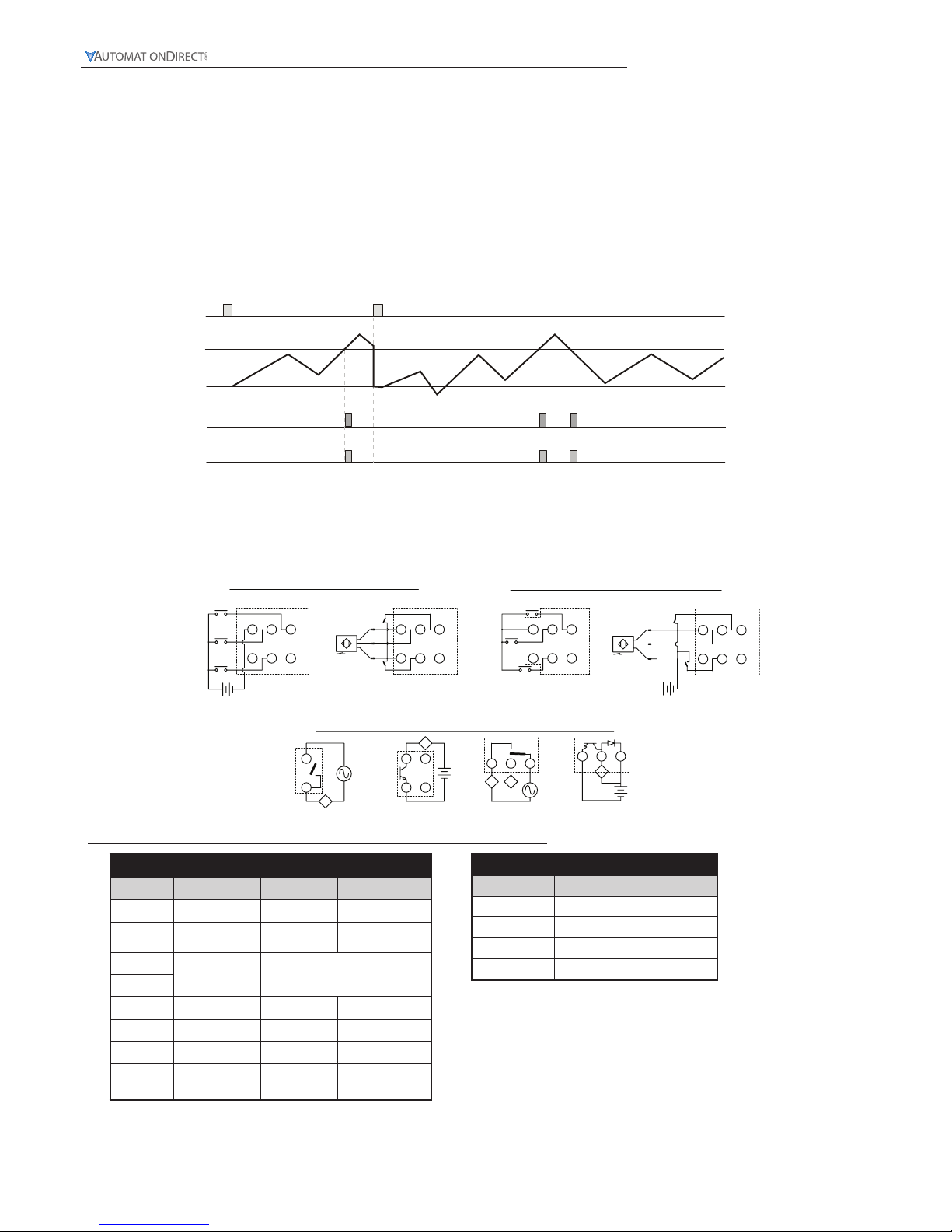
Mode S (S) and Mode T (t)
When the count present value PV counts up to the count setting value SV both outputs 1 and 2 will turn ON.
When the count PV counts down to the count SV, both outputs 1 and 2 will turn OFF. The count PV will
continue to increment or decrement with each input signal.
The leading edge of a “reset” input signal at RST1 will turn OFF both outputs, reset the count PV to 0, and
prohibit an input signal from incrementing or decrementing the count PV. The trailing edge of the “reset”
signal at RST1 enables counting to begin.
The “reset” signal minimum pulse width is set by reset pulse width parameter (
rtSr
) or DIP Switch 8.
RESET
999999
SV
PV
OUT2
OUT1
Stage 1
Input Mode UdA
Output Mode S and T
0
Page 29
Digital Counter / Timer / Tach User Manual, 1st Ed.
1-800-633-0405
2-16
Outputs
Load
Load
OUT1
NPN/
SINKING
OUT2
SPDT
Load
OUT1
SPST
0V CP1
CP2/
GATE (Pause)
+12V RST1
RST2/
START
CP2
Input
CP1
Input
Reset
0V CP1
+12V RST1
RST2/
START
Reset
0V CP1
+12V RST1
RST2/
START
Reset
PNP
INPUTS
L-
Load
OUT2
NPN/
SINKING
Load
0V CP1
+12V RST1
RST2/
START
Reset
L-
L+
NPN
INPUTS
CP1
Input
CP2
Input
CP2
Input
CP1
Input
CP1
Input
CP2
Input
L+
+VDC 0VDC
Externally Powered
Internally Powered
+VDC 0VDC
Externally Powered
Internally Powered
(Optional)
(Optional)
(Optional)
(Optional)
+VDC
0VDC
+VDC
0VDC
10
9
321
15
14
10
15
876
1312
11
876
131211
876
131211
321
876
131211
Counter Wiring Examples
CP2/
GATE (Pause)
CP2/
GATE (Pause)
CP2/
GATE (Pause)
Mode D (d)
When the count present value PV counts up or counts down to the count setting value SV both outputs 1 and
2 will turn ON momentarily for the time set in the output pulse width parameter (
tout2
). The count PV will
continue to increment or decrement with each input signal.
The leading edge of a “reset” input signal at RST1 will turn OFF both outputs, reset the count PV to 0, and
prohibit an input signal from incrementing or decrementing the count PV. The trailing edge of the “reset”
signal at RST1 enables counting to begin.
The “reset” signal minimum pulse width is set by reset pulse width parameter (
rtSr
) or DIP Switch 8.
RESET
999999
SV
PV
OUT2
OUT1
Stage 1
Input Mode UdA
Output Mode D
T
T
TTT
T
0
Output Mode - Table 2
Switch 3 Switch 4 Output Mode
OFF OFF
F
ON OFF
N
OFF ON
C
ON ON
R
Dip Switch Settings - Table 1
Switch Function Off On
1 Dip switch Disabled Enabled
2 Counting mode Counting up Counting down
3
Output mode See Output Mode Table - Table 2
4
5 Counting speed 30cps 10Kps
6 Reserved - -
7 Input signal NPN PNP
8
Reset signal
pulse width
20 ms 1 ms
DIP Switch Set Up of the CTT Parameters:
Page 30

Digital Counter / Timer / Tach User Manual, 1st Ed.
2-17
www.automationdirect.com
Select functions: There are 4 modes in CTT, (left to right) timer, counter, tachometer and timer + counter.
Select counter functions: 1-stage counting, 2-stage counting, batch counting, total counting, dual counting.
Ä
CntFun sta6e1 sta6e2 batCh total dual
C–inPt
––UP down ud–a ud–b ud–C
Select input modes: counting up, counting down, counting up/command counting down, counting up/counting down,
quadrature input.
C–otmd
FnCr kp
q
a
s
t
d
Select output modes: CTT offer 11 output modes, among which mode S, T and D are only valid with input modes
Ud_A, Ud_b and Ud_C.
Select counting speed: Maximum 10Kcps; others 5K, 1K, 200, 30 and 1cps.
C–Sped –10k ––5k ––1k –200 ––30
t–out1
Pulse width of output 1: The default output time is 0.02 second. When the parameter is set to 0.00 second, the
output status will be maintained ON. Range = 0.00 to 99.99 seconds.
–––1
–002 –000
t–out2
Pulse width of output 2: This paramter is adjustable according to different output modes selected. If the output mode is C,
the default output time will be 0.02 second. Range = 0.01 to 99.99 seconds.
–002 –000
–point
Set up the position of decimal point: 0 (no decimal point), 1 (one digit after decimal point), 2 (two digits after decimal
point), 3 (three digits after decimal point).
0123
psCale 1000
Set up pre-scale value: 1.000 (default 1:1) Range: 0.001 to 99.999
–pwers
Save the data while switching off the power: When SAVE is selected, the PV will be saved; when CLEAR is selected,
the PV will not be saved.
Clear save
–rtsr
Set up minimum width of reset signal: Default = 20ms; 1ms is also selectable
––20 –––1
inptlC
Select input signal types: NPN and PNP
–npn –pnp
Back to Top
–FunC Cont taCh –mixtime
Ä
Ä
Ä
Ä
Ä
Ä
Ä
Ä
Ä
Ä
Ä
or
or
or or or
or or or or or
oror
oror
or
or or or or or or
or
or or
or or
or
or or
or or or or
or or
or or
or or or or
or
or
or
or
or
or
To enter the page for parameter setting of the counter, press Ä for the main menu for more than 3 seconds.
After the setup is completed, press Ä for more than 3 seconds under any of the parameter page you are in and
return to the main menu.
Keypad set up of the parameters for 1-Stage Counting:
Used to convert the displayed PV into engineering unit, such as RPM, inches, millimeters, feet per minute etc. See Tachometer Examples in Chapter 6
Page 31

Digital Counter / Timer / Tach User Manual, 1st Ed.
1-800-633-0405
2-18
1-Stage Counting (
StA6E 1
)
A single count setting value SV is available in 1-Stage Counting. Both Outputs 1 and 2 operate concurrently and
will turn ON momentarily for the time set in the output pulse width parameter (
tout2
) or will be maintained ON
depending on the Output Mode selected.
CTT Counter Functions
1-Stage Counting (StA6E 1)
Counting Up / Counting Down (Udb)
Counting Up / Counting Down (
Ud b
)
Each leading edge of the input signal at CP1 will increment the count present value (PV) by 1.
Input Mode:
Mode F (F)
When the count present value PV counts up to the count setting
value SV, both outputs 1 and 2 will turn ON. The count PV
will continue to increment or decrement with each input signal.
The leading edge of a “reset” input signal at RST1 will turn
OFF both outputs, reset the count PV to 0, and prohibit an
input signal from incrementing or decrementing the count PV.
The trailing edge of the “reset” signal at RST1 enables counting
to begin.
The “reset” signal minimum pulse width is set by reset pulse
width parameter (
rtSr
) or DIP Switch 8.
Output Modes:
Mode N (n)
When the count present value PV counts up to the count
setting value SV, both outputs 1 and 2 will turn ON. The count
PV will remain at the count SV regardless of additional input
signals.
The leading edge of a “reset” input signal at RST1 will turn
OFF both outputs, reset the count PV to 0, and prohibit an
input signal from incrementing or decrementing the count PV.
The trailing edge of the “reset” signal at RST1 enables counting
to begin.
The “reset” signal minimum pulse width is set by reset pulse
width parameter (
rtSr
) or DIP Switch 8.
Each leading edge of the input signal at CP2 will decrement the count present value (PV) by 1.
999999
RESET
SV
OUT2
OUT1
PV
Stage 1
Input Mode UdB
Output Mode F
0
Stage 1
Input Mode UdB
Output Mode N
RESET
999999
SV
PV
OUT2
OUT1
0
Counting up/down
Page 32

Digital Counter / Timer / Tach User Manual, 1st Ed.
2-19
www.automationdirect.com
Mode C (C)
When the count present value PV counts up to the count setting value
SV, both outputs 1 and 2 will turn ON momentarily for the time set
in the output pulse width parameter (tout2) and the count PV will
reset automatically to 0.
The leading edge of a “reset” input signal at RST1 will turn both
outputs OFF, reset the count PV to 0 and prohibit an input signal
from incrementing or decrementing the count PV. The trailing edge
of the “reset” signal at RST1 enables counting to begin.
The “reset” signal minimum pulse width is set by reset pulse width
parameter (
rtSr
) or DIP Switch 8.
Mode R (r)
When the count present value PV counts up to the count setting value
SV, both outputs 1 and 2 will turn ON momentarily for the time set in
the output pulse width parameter (
tout2
). The count PV is prohibited from incrementing or decrementing until the end of the output
pulse time (
tout2
) when the outputs turn OFF and the count PV is
reset automatically to 0.
The leading edge of a “reset” input signal at RST1 will turn OFF both
outputs, reset the count PV to 0 and prohibit an input signal from
incrementing or decrementing the count PV. The trailing edge of the
“reset” signal at RST1 enables counting to begin.
The “reset” signal minimum pulse width is set by reset pulse width
parameter (
rtSr
) or DIP Switch 8.
Mode K (k)
When the count present value PV counts up or counts down to the
count setting value SV, both outputs 1 and 2 will turn ON momentarily for the time set in the output pulse width parameter (
tout2
).
The count PV will continue to increment or decrement with each
input signal.
The leading edge of a “reset” input signal at RST1 will turn OFF both
outputs, reset the count PV to 0 and prohibit an input signal from
incrementing or decrementing the count PV. The trailing edge of the
“reset” signal at RST1 enables counting to begin.
The “reset” signal minimum pulse width is set by reset pulse width
parameter (
rtSr
) or DIP Switch 8.
T
T
RESET
999999
SV
PV
OUT2
OUT1
Stage 1
Input Mode UdB
Output Mode C
T
T
0
T
T
T
T
Stage 1
Input Mode UdB
Output Mode R
RESET
999999
SV
PV
OUT2
OUT1
0
RESET
999999
SV
PV
OUT2
OUT1
Stage 1
Input Mode UdB
Output Mode K
TT
T
T
T
T
0
T
T
T
Stage 1
Input Mode UdB
Output Mode P
RESET
999999
SV
PV
OUT2
OUT1
T
0
Mode P (P)
When the count present value PV counts up to the count setting value
SV, both outputs 1 and 2 will turn ON momentarily for the time set
in the output pulse width parameter (
tout2
). The count PV display
is prohibited from incrementing or decrementing until the end of the
output pulse time when both outputs turn OFF and the count PV is
reset automatically to 0 and any input signals that occurred during the
output pulse time.
The leading edge of a “reset” input signal at RST1 will turn OFF both
outputs, reset the count PV to 0 and prohibit an input signal from
incrementing or decrementing the count PV. The trailing edge of the
“reset” signal at RST1 enables counting to begin.
The “reset” signal minimum pulse width is set by reset pulse width
parameter (
rtSr
) or DIP Switch 8.
Page 33

Digital Counter / Timer / Tach User Manual, 1st Ed.
1-800-633-0405
2-20
Mode Q (q)
When the count present value PV counts up to the count setting
value SV, both outputs 1 and 2 will turn ON momentarily for the
time set in the output pulse width parameter (
tout2
). The count
PV will continue to increment or decrement with each input signal
until the end of the output pulse time when the outputs turn OFF
and the count PV is reset automatically to 0.
The leading edge of a “reset” input signal at RST1 will turn OFF
both outputs, reset the count PV to 0 and prohibit an input signal
from incrementing or decrementing the count PV. The trailing edge
of the “reset” signal at RST1 enables counting to begin.
The “reset” signal minimum pulse width is set by reset pulse width
parameter (
rtSr
) or DIP Switch 8.
Mode A (A)
When the count present value PV counts up to the count setting
value SV, both outputs 1 and 2 will turn ON momentarily for
the time set in the output pulse width parameter (
tout2
). The
count PV will remain at the count SV regardless of additional input
signals.
The leading edge of a “reset” input signal at RST1 will turn OFF
both outputs, reset the count PV to 0 and prohibit an input signal
from incrementing or decrementing the count PV. The trailing
edge of the “reset” signal at RST1 enables counting to begin.
The “reset” signal minimum pulse width is set by reset pulse width
parameter (
rtSr
) or DIP Switch 8.
TT
RESET
999999
SV
PV
OUT2
OUT1
TT
Stage 1
Input Mode UdB
Output Mode Q
0
T
T
RESET
999999
SV
PV
OUT2
OUT1
T
T
Stage 1
Input Mode UdB
Output Mode A
0
Mode S (S) and Mode T (t)
When the count present value PV counts up to the count setting value SV both outputs 1 and 2 will turn ON.
When the count PV counts down to the count SV, both outputs 1 and 2 will turn OFF. The count PV will
continue to increment or decrement with each input signal.
The leading edge of a “reset” input signal at RST1 will turn OFF both outputs, reset the count PV to 0, and
prohibit an input signal from incrementing or decrementing the count PV. The trailing edge of the “reset”
signal at RST1 enables counting to begin.
The “reset” signal minimum pulse width is set by reset pulse width parameter (
rtSr
) or DIP Switch 8.
RESET
999999
SV
PV
OUT2
OUT1
Stage 1
Input Mode UdB
Output Mode S & T
0
Page 34

Digital Counter / Timer / Tach User Manual, 1st Ed.
2-21
www.automationdirect.com
Outputs
Load
Load
OUT1
NPN/
SINKING
OUT2
SPDT
Load
OUT1
SPST
0V CP1
CP2/
GATE (Pause)
+12V RST1
RST2/
START
CP2
Input
CP1
Input
Reset
0V CP1
+12V RST1
RST2/
START
Reset
0V CP1
+12V RST1
RST2/
START
Reset
PNP
INPUTS
L-
Load
OUT2
NPN/
SINKING
Load
0V CP1
+12V RST1
RST2/
START
Reset
L-
L+
NPN
INPUTS
CP1
Input
CP2
Input
CP2
Input
CP1
Input
CP1
Input
CP2
Input
L+
+VDC 0VDC
Externally Powered
Internally Powered
+VDC 0VDC
Externally Powered
Internally Powered
(Optional)
(Optional)
(Optional)
(Optional)
+VDC
0VDC
+VDC
0VDC
10
9
321
15
14
10
15
876
1312
11
876
131211
876
131211
321
876
131211
Counter Wiring Examples
CP2/
GATE (Pause)
CP2/
GATE (Pause)
CP2/
GATE (Pause)
Mode D (d)
When the count present value PV counts up or counts down to the count setting value SV, both outputs 1 and
2 will turn ON momentarily for the time set in the output pulse width parameter (
tout2
). The count PV will
continue to increment or decrement with each input signal.
The leading edge of a “reset” input signal at RST1 will turn OFF both outputs, reset the count PV to 0, and
prohibit an input signal from incrementing or decrementing the count PV. The trailing edge of the “reset”
signal at RST1 enables counting to begin.
The “reset” signal minimum pulse width is set by reset pulse width parameter (
rtSr
) or DIP Switch 8.
RESET
999999
SV
PV
OUT2
OUT1
Stage 1
Input Mode UdB
Output Mode D
T
T
TTT
T
0
Output Mode - Table 2
Switch 3 Switch 4 Output Mode
OFF OFF
F
ON OFF
N
OFF ON
C
ON ON
R
Dip Switch Settings - Table 1
Switch Function Off On
1 Dip switch Disabled Enabled
2 Counting mode Counting up Counting down
3
Output mode See Output Mode Table - Table 2
4
5 Counting speed 30cps 10Kps
6 Reserved - -
7 Input signal NPN PNP
8
Reset signal
pulse width
20 ms 1 ms
DIP Switch Set Up of the CTT Parameters:
Page 35

Digital Counter / Timer / Tach User Manual, 1st Ed.
1-800-633-0405
2-22
Select functions: There are 4 modes in CTT, (left to right) timer, counter, tachometer and timer + counter.
Select counter functions: 1-stage counting, 2-stage counting, batch counting, total counting, dual counting.
Ä
CntFun sta6e1 sta6e2 batCh total dual
C–inPt
––UP down ud–a ud–b ud–C
Select input modes: counting up, counting down, counting up/command counting down, counting up/counting down,
quadrature input.
C–otmd
FnCr kp
q
a
s
t
d
Select output modes: CTT offer 11 output modes, among which mode S, T and D are only valid with input modes
Ud_A, Ud_b and Ud_C.
Select counting speed: Maximum 10Kcps; others 5K, 1K, 200, 30 and 1cps.
C–Sped –10k ––5k ––1k –200 ––30
t–out1
Pulse width of output 1: The default output time is 0.02 second. When the parameter is set to 0.00 second, the
output status will be maintained ON. Range = 0.00 to 99.99 seconds.
–––1
–002 –000
t–out2
Pulse width of output 2: This paramter is adjustable according to different output modes selected. If the output mode is C,
the default output time will be 0.02 second. Range = 0.01 to 99.99 seconds.
–002 –000
–point
Set up the position of decimal point: 0 (no decimal point), 1 (one digit after decimal point), 2 (two digits after decimal
point), 3 (three digits after decimal point).
0123
psCale 1000
Set up pre-scale value: 1.000 (default 1:1) Range: 0.001 to 99.999
–pwers
Save the data while switching off the power: When SAVE is selected, the PV will be saved; when CLEAR is selected,
the PV will not be saved.
Clear save
–rtsr
Set up minimum width of reset signal: Default = 20ms; 1ms is also selectable
––20 –––1
inptlC
Select input signal types: NPN and PNP
–npn –pnp
Back to
Top
–FunC Cont taCh –mixtime
Ä
Ä
Ä
Ä
Ä
Ä
Ä
Ä
Ä
Ä
Ä
or
or or or or
or or or or or
oror
oror
or
or or or or or or
or or or or or or
or or
or or or or
or or
or or
or or or or
or
or
or
or
or
or
To enter the page for parameter setting of the counter, press Ä for the main menu for more than 3 seconds.
After the setup is completed, press Ä for more than 3 seconds under any of the parameter page you are in and
return to the main menu.
Keypad set up of the parameters for 1-Stage Counting:
Used to convert the displayed PV into engineering unit, such as RPM, inches, millimeters, feet per minute etc. See Tachometer Examples in Chapter 6
Page 36

Digital Counter / Timer / Tach User Manual, 1st Ed.
2-23
www.automationdirect.com
1-Stage Counting (
StA6E 1
)
A single count setting value SV is available in 1-Stage Counting. Both Outputs 1 and 2 operate concurrently and
will turn ON momentarily for the time set in the output pulse width parameter (
tout2
) or will be maintained ON
depending on the Output Mode selected.
CTT Counter Functions
1-Stage Counting (StA6E 1)
Quadrature (UdC)
Quadrature (
Ud C
)
When the quadrature input signal at CP1 changes before the input signal at CP2, the trailing edge of CP2
will increment the count present value PV by 1.
Input Mode:
Mode F (F)
When the count present value PV counts up to the count setting
value SV, both outputs 1 and 2 will turn ON. The count PV
will continue to increment or decrement with each input signal.
The leading edge of a “reset” input signal at RST1 will turn
OFF both outputs, reset the count PV to 0, and prohibit an
input signal from incrementing or decrementing the count PV.
The trailing edge of the “reset” signal at RST1 enables counting
to begin.
The “reset” signal minimum pulse width is set by reset pulse
width parameter (
rtSr
) or DIP Switch 8.
Output Modes:
Mode N (n)
When the count present value PV counts up to the count
setting value SV, both outputs 1 and 2 will turn ON. The count
PV will remain at the count SV regardless of additional input
signals.
The leading edge of “reset” input signal at RST1 will turn OFF
both outputs, reset the count PV to 0, and prohibit an input
signal from incrementing or decrementing the count PV. The
trailing edge of the “reset” signal at RST1 enables counting to
begin.
The “reset” signal minimum pulse width is set by reset pulse
width parameter (
rtSr
) or DIP Switch 8
When the quadrature input signal at CP2 changes before the input signal at CP1, the leading edge of CP2
will decrement the count present value PV by 1.
999999
RESET
SV
OUT2
OUT1
PV
Stage 1
Input Mode UdC
Output Mode F
0
Stage 1
Input Mode UdC
Output Mode N
RESET
999999
SV
PV
OUT2
OUT1
0
Quadrature input
B B B B
0
11
2
2
3
H
L
CP1
CP2
Present
Value
0
Note: has to be larger than width of 1/2 min. input signal.
B
H
L
0
Page 37

Digital Counter / Timer / Tach User Manual, 1st Ed.
1-800-633-0405
2-24
Mode C (C)
When the count present value PV counts up to the count setting value
SV, both outputs 1 and 2 will turn ON momentarily for the time set
in the output pulse width parameter (
tout2
) and the count PV will
reset automatically to 0.
The leading edge of a “reset” input signal at RST1 will turn both
outputs OFF, reset the count PV to 0 and prohibit an input signal
from incrementing or decrementing the count PV. The trailing edge
of the “reset” signal at RST1 enables counting to begin.
The “reset” signal minimum pulse width is set by reset pulse width
parameter (
rtSr
) or DIP Switch 8.
Mode R (r)
When the count present value PV counts up to the count setting value
SV, both outputs 1 and 2 will turn ON momentarily for the time set in
the output pulse width parameter (
tout2
). The count PV is prohibited from incrementing or decrementing until the end of the output
pulse time (
tout2
) when the outputs turn OFF and the count PV is
reset automatically to 0.
The leading edge of a “reset” input signal at RST1 will turn OFF both
outputs, reset the count PV to 0 and prohibit an input signal from
incrementing or decrementing the count PV. The trailing edge of the
“reset” signal at RST1 enables counting to begin.
The “reset” signal minimum pulse width is set by reset pulse width
parameter (
rtSr
) or DIP Switch 8.
Mode K (k)
When the count present value PV counts up or counts down to the
count setting value SV, both outputs 1 and 2 will turn ON momentarily for the time set in the output pulse width parameter (
tout2
).
The count PV will continue to increment or decrement with each
input signal.
The leading edge of a “reset” input signal at RST1 will turn OFF both
outputs, reset the count PV to 0 and prohibit an input signal from
incrementing or decrementing the count PV. The trailing edge of the
“reset” signal at RST1 enables counting to begin.
The “reset” signal minimum pulse width is set by reset pulse width
parameter (
rtSr
) or DIP Switch 8.
T
T
RESET
999999
SV
PV
OUT2
OUT1
Stage 1
Input Mode UdC
Output Mode C
T
T
0
T
T
T
T
Stage 1
Input Mode UdC
Output Mode R
RESET
999999
SV
PV
OUT2
OUT1
0
RESET
999999
SV
PV
OUT2
OUT1
Stage 1
Input Mode UdC
Output Mode K
TT
T
T
T
T
0
T
T
T
Stage 1
Input Mode UdC
Output Mode P
RESET
999999
SV
PV
OUT2
OUT1
T
0
Mode P (P)
When the count present value PV counts up to the count setting value
SV, both outputs 1 and 2 will turn ON momentarily for the time set
in the output pulse width parameter (
tout2
). The count PV display
is prohibited from incrementing or decrementing until the end of the
output pulse time when both outputs turn OFF and the count PV is
reset automatically to 0 and any input signals that occurred during the
output pulse time.
The leading edge of a “reset” input signal at RST1 will turn OFF both
outputs, reset the count PV to 0 and prohibit an input signal from
incrementing or decrementing the count PV. The trailing edge of the
“reset” signal at RST1 enables counting to begin.
The “reset” signal minimum pulse width is set by reset pulse width
parameter (
rtSr
) or DIP Switch 8.
Page 38

Digital Counter / Timer / Tach User Manual, 1st Ed.
2-25
www.automationdirect.com
Mode Q (q)
When the count present value PV counts up to the count setting
value SV, both outputs 1 and 2 will turn ON momentarily for the
time set in the output pulse width parameter (
tout2
). The count
PV will continue to increment or decrement with each input signal
until the end of the output pulse time when the outputs turn OFF
and the count PV is reset automatically to 0.
The leading edge of a “reset” input signal at RST1 will turn OFF
both outputs, reset the count PV to 0 and prohibit an input signal
from incrementing or decrementing the count PV. The trailing edge
of the “reset” signal at RST1 enables counting to begin.
The “reset” signal minimum pulse width is set by reset pulse width
parameter (
rtSr
) or DIP Switch 8.
Mode A (A)
When the count present value PV counts up to the count setting
value SV, both outputs 1 and 2 will turn ON momentarily for
the time set in the output pulse width parameter (
tout2
). The
count PV will remain at the count SV regardless of additional input
signals.
The leading edge of a “reset” input signal at RST1 will turn OFF
both outputs, reset the count PV to 0 and prohibit an input signal
from incrementing or decrementing the count PV. The trailing
edge of the “reset” signal at RST1 enables counting to begin.
The “reset” signal minimum pulse width is set by reset pulse width
parameter (
rtSr
) or DIP Switch 8.
TT
RESET
999999
SV
PV
OUT2
OUT1
TT
Stage 1
Input Mode UdC
Output Mode Q
0
T
T
RESET
999999
SV
PV
OUT2
OUT1
T
T
Stage 1
Input Mode UdC
Output Mode A
0
Mode S (S) and Mode T (t)
When the count present value PV counts up to the count setting value SV both outputs 1 and 2 will turn ON.
When the count PV counts down to the count SV, both outputs 1 and 2 will turn OFF. The count PV will
continue to increment or decrement with each input signal.
The leading edge of a “reset” input signal at RST1 will turn OFF both outputs, reset the count PV to 0, and
prohibit an input signal from incrementing or decrementing the count PV. The trailing edge of the “reset”
signal at RST1 enables counting to begin.
The “reset” signal minimum pulse width is set by reset pulse width parameter (
rtSr
) or DIP Switch 8.
RESET
999999
SV
PV
OUT2
OUT1
Stage 1
Input Mode UdC
Output Mode S & T
0
Page 39

Digital Counter / Timer / Tach User Manual, 1st Ed.
1-800-633-0405
2-26
Outputs
Load
Load
OUT1
NPN/
SINKING
OUT2
SPDT
Load
OUT1
SPST
0V CP1
CP2/
GATE (Pause)
+12V RST1
RST2/
START
CP2
Input
CP1
Input
Reset
0V CP1
+12V RST1
RST2/
START
Reset
0V CP1
+12V RST1
RST2/
START
Reset
PNP
INPUTS
L-
Load
OUT2
NPN/
SINKING
Load
0V CP1
+12V RST1
RST2/
START
Reset
L-
L+
NPN
INPUTS
CP1
Input
CP2
Input
CP2
Input
CP1
Input
CP1
Input
CP2
Input
L+
+VDC 0VDC
Externally Powered
Internally Powered
+VDC 0VDC
Externally Powered
Internally Powered
(Optional)
(Optional)
(Optional)
(Optional)
+VDC
0VDC
+VDC
0VDC
10
9
321
15
14
10
15
876
1312
11
876
131211
876
131211
321
876
131211
Counter Wiring Examples
CP2/
GATE (Pause)
CP2/
GATE (Pause)
CP2/
GATE (Pause)
Mode D (d)
When the count present value PV counts up or counts down to the count setting value SV, both outputs 1 and
2 will turn ON momentarily for the time set in the output pulse width parameter (
tout2
). The count PV will
continue to increment or decrement with each input signal.
The leading edge of a “reset” input signal at RST1 will turn OFF both outputs, reset the count PV to 0, and
prohibit an input signal from incrementing or decrementing the count PV. The trailing edge of the “reset”
signal at RST1 enables counting to begin.
The “reset” signal minimum pulse width is set by reset pulse width parameter (
rtSr
) or DIP Switch 8.
RESET
999999
SV
PV
OUT2
OUT1
Stage 1
Input Mode UdC
Output Mode D
T
T
TTT
T
0
Output Mode - Table 2
Switch 3 Switch 4 Output Mode
OFF OFF
F
ON OFF
N
OFF ON
C
ON ON
R
Dip Switch Settings - Table 1
Switch Function Off On
1 Dip switch Disabled Enabled
2 Counting mode Counting up Counting down
3
Output mode See Output Mode Table - Table 2
4
5 Counting speed 30cps 10Kps
6 Reserved - -
7 Input signal NPN PNP
8
Reset signal
pulse width
20 ms 1 ms
DIP Switch Set Up of the CTT Parameters:
Page 40

Digital Counter / Timer / Tach User Manual, 1st Ed.
2-27
www.automationdirect.com
Select functions: There are 4 modes in CTT, (left to right) timer, counter, tachometer and timer + counter.
Select counter functions: 1-stage counting, 2-stage counting, batch counting, total counting, dual counting.
Ä
CntFun sta6e1 sta6e2 batCh total dual
C–inPt
––UP down ud–a ud–b ud–C
Select input modes: counting up, counting down, counting up/command counting down, counting up/counting down,
quadrature input.
C–otmd
FnCr kp
q
a
s
t
d
Select output modes: CTT offer 11 output modes, among which mode S, T and D are only valid with input modes
Ud_A, Ud_b and Ud_C.
Select counting speed: Maximum 10Kcps; others 5K, 1K, 200, 30 and 1cps.
C–Sped –10k ––5k ––1k –200 ––30
t–out1
Pulse width of output 1: The default output time is 0.02 second. When the parameter is set to 0.00 second, the
output status will be maintained ON. Range = 0.00 to 99.99 seconds.
–––1
–002 –000
t–out2
Pulse width of output 2: This paramter is adjustable according to different output modes selected. If the output mode is C,
the default output time will be 0.02 second. Range = 0.01 to 99.99 seconds.
–002 –000
–point
Set up the position of decimal point: 0 (no decimal point), 1 (one digit after decimal point), 2 (two digits after decimal
point), 3 (three digits after decimal point).
0123
psCale 1000
Set up pre-scale value: 1.000 (default 1:1) Range: 0.001 to 99.999
–pwers
Save the data while switching off the power: When SAVE is selected, the PV will be saved; when CLEAR is selected,
the PV will not be saved.
Clear save
–rtsr
Set up minimum width of reset signal: Default = 20ms; 1ms is also selectable
––20 –––1
inptlC
Select input signal types: NPN and PNP
–npn –pnp
Back to Top
–FunC Cont taCh –mixtime
or
or
or or or
or or or or or
oror
oror
or
or or or or or or
or
or or
or or
or
or or
or or or or
or or
or or
or or or or
or
or
or
or
or
or
Ä
Ä
Ä
Ä
Ä
Ä
Ä
Ä
Ä
Ä
Ä
To enter the page for parameter setting of the counter, press Ä for the main menu for more than 3 seconds.
After the setup is completed, press Ä for more than 3 seconds under any of the parameter page you are in and
return to the main menu.
Keypad set up of the parameters for 1-Stage Counting:
Used to convert the displayed PV into engineering unit, such as RPM, inches, millimeters, feet per minute etc. See Tachometer Examples in Chapter 6
Page 41

Digital Counter / Timer / Tach User Manual, 1st Ed.
1-800-633-0405
2-28
2-Stage Counting (
StA6E 2
)
In 2-Stage Counting, count setting value SV1 controls Output 1 and count setting value SV2 controls Output 2.
Output 1 will turn ON momentarily for the time set in the output pulse width parameter (
tout1
) or will be maintained ON (tout1 set to 0.00). Output 2 will turn ON momentarily for the time set in the output pulse width parameter (
tout2
) or will be maintained ON depending on the output mode selected.
CTT Counter Functions
2-Stage Counting (StA6E 2)
Counting Up (UP)
Counting Up (UP)
With the input signal OFF at input CP2, each leading edge of
the input signal at CP1 will increment the count present value
PV by 1. Turning ON the input signal at CP2, will prohibit
the input signal at CP1 from incrementing the PV.
Input Mode:
Mode F (F)
When the count present value PV counts up to the count
setting value SV1, Output 1 will turn ON momentarily for
the time set in the output pulse width parameter (
tout1
) or
will be maintained ON if the output pulse width parameter
(
tout1
) is set to 0.00. When the count PV counts up to the
count setting value SV2, Output 2 will turn ON. The count PV
will continue to increment with each input signal.
The leading edge of a “reset” input signal at RST1 will turn
OFF both outputs, reset the count PV to 0, and prohibit an
input signal from incrementing the count PV. The trailing edge
of the “reset” signal at RST1 enables counting to begin.
The “reset” signal minimum pulse width is set by reset pulse
width parameter (
rtSr
) or DIP Switch 8.
Output Modes:
With the input signal ON at input CP1, each trailing edge of
the input signal at CP2 will increment the count present value
PV by 1. Turning OFF the input signal at CP1, will prohibit
the input signal at CP2 from incrementing the PV.
999999
RESET
SV2
SV1
OUT2
OUT1
PV
T1 T1
Stage 2
Input Mode UP
Output Mode F
Note: T1 momentary ON time set in output
pulse parameter (tout1), setting tout1=0.00
results in output 1 maintained ON.
0
Prohibit
A
A
0
1
2
3
4
5
H
L
H
L
0
CP1
CP2
Present
Value
CP1: Counter input prohibited CP2: Counter input
Note: has to be larger than width of min. Input signal
A
Counting up
Prohibit
A
A
0
1
2
3
4
H
L
H
L
0
CP1
CP2
Present
Value
CP1: Counter input CP2: Counter input prohibited
Note: has to be larger than width of min. Input signal
A
Page 42

Digital Counter / Timer / Tach User Manual, 1st Ed.
2-29
www.automationdirect.com
Mode N (n)
When the count present value PV counts up to the count
setting value SV1, Output 1 will turn ON momentarily for the
time set in the output pulse width parameter (
tout1
) or will be
maintained ON if the output pulse width parameter (
tout1
) is
set to 0.00. When the count PV counts up to the count setting
value SV2, Output 2 will turn ON. The count PV will remain
at the count SV2 regardless of additional input signals.
The leading edge of a “reset” input signal at RST1 will turn
OFF both outputs, reset the count PV to 0, and prohibit an
input signal from incrementing the count PV. The trailing edge
of the “reset” signal at RST1 enables counting to begin.
The “reset” signal minimum pulse width is set by reset pulse
width parameter (
rtSr
) or DIP Switch 8
RESET
999999
SV2
SV1
PV
OUT2
OUT1
T1 T1
Stage 2
Input Mode UP
Output Mode N
Note: T1 momentary ON time set in output
pulse parameter (tout1), setting tout1=0.00
results in output 1 maintained ON.
0
Mode C (C)
When the count present value PV counts up to the count
setting value SV1, Output 1 will turn ON momentarily for the
time set in the output pulse width parameter (
tout1
) or will be
maintained ON if the output pulse width parameter (
tout1
) is
set to 0.00. When the count PV counts up to the count setting
value SV2, Output 2 will turn ON momentarily for the time set
in the output pulse width parameter (
tout2
) and the count PV
will reset automatically to 0. If Output 1 is ON when Output
2 turns OFF, Output 1 will also turn OFF.
The leading edge of a “reset” input signal at RST1 will turn
OFF both outputs, reset the count PV to 0 and prohibit an
input signal from incrementing the count PV. The trailing edge
of the “reset” signal at RST1 enables counting to begin.
The “reset” signal minimum pulse width is set by reset pulse
width parameter (
rtSr
) or DIP Switch 8.
RESET
999999
SV2
PV
OUT2
OUT1
SV1
T1 T1 T1
T2
T2 T2
Stage 2
Input Mode UP
Output Mode C
Note: T1 momentary ON time set in output
pulse parameter (tout1), setting tout1=0.00
results in output 1 maintained ON.
T2 = Momentary ON time set in output pulse
parameter (tout2).
0
Mode R (r)
When the count present value PV counts up to the count
setting value SV1, Output 1 will turn ON momentarily for the
time set in the output pulse width parameter (
tout1
) or will be
maintained ON if the output pulse width parameter (
tout1
) is
set to 0.00. When the count PV counts up to the count setting
value SV2, Output 2 will turn ON momentarily for the time set
in the output pulse width parameter (
tout2
). The count PV is
prohibited from incrementing until the end of the output pulse
time (
tout2
) when both outputs turn OFF and the count PV
is reset automatically to 0.
The leading edge of a “reset” input signal at RST1 will turn
OFF both outputs, reset the count PV to 0 and prohibit an
input signal from incrementing the count PV. The trailing edge
of the “reset” signal at RST1 enables counting to begin.
The “reset” signal minimum pulse width is set by reset pulse
width parameter (
rtSr
) or DIP Switch 8.
RESET
999999
SV2
SV1
PV
OUT2
OUT1
T1 T1
T2
T2
Stage 2
Input Mode UP
Output Mode R
Note: T1 momentary ON time set in output
pulse parameter (tout1), setting tout1=0.00
results in output 1 maintained ON.
T2 = Momentary ON time set in output pulse
parameter (tout2).
0
Page 43

Digital Counter / Timer / Tach User Manual, 1st Ed.
1-800-633-0405
2-30
Mode K (k)
When the count present value PV counts up to the count
setting value SV1, Output 1 will turn ON momentarily for
the time set in the output pulse width parameter (
tout1
) or
will be maintained ON if the output pulse width parameter
(
tout1
) is set to 0.00. When the count PV counts up to the
count setting value SV2, Output 2 will turn ON momentarily
for the time set in the output pulse width parameter (
tout2
).
If Output 1 is ON when Output 2 turns OFF, Output 1 will
also turn OFF. The count PV will continue to increment with
each input signal.
The leading edge of a “reset” input signal at RST1 will turn
OFF both outputs, reset the count PV to 0 and prohibit an
input signal from incrementing the count PV. The trailing edge
of the “reset” signal at RST1 enables counting to begin.
The “reset” signal minimum pulse width is set by reset pulse
width parameter (
rtSr
) or DIP Switch 8.
RESET
999999
SV1
SV2
PV
OUT2
OUT1
T1
T1
T2
T2
Stage 2
Input Mode UP
Output Mode K
Note: T1 momentary ON time set in output
pulse parameter (tout1), setting tout1=0.00
results in output 1 maintained ON.
T2 = Momentary ON time set in output pulse
parameter (tout2).
0
Mode P (P)
When the count present value PV counts up to the count
setting value SV1, Output 1 will turn ON momentarily for the
time set in the output pulse width parameter (
tout1
) or will be
maintained ON if the output pulse width parameter (
tout1
) is
set to 0.00. When the count PV counts up to the count setting
value SV2, Output 2 will turn ON momentarily for the time
set in the output pulse width parameter (
tout2
). The count
PV display is prohibited from incrementing until the end of the
output pulse time (
tout2
) when both outputs turn OFF and
the count PV is reset automatically to 0 and any input signals
that occurred during the output pulse time.
The leading edge of a “reset” input signal at RST1 will turn
OFF both outputs, reset the count PV to 0 and prohibit an
input signal from incrementing the count PV. The trailing edge
of the “reset” signal at RST1 enables counting to begin.
The “reset” signal minimum pulse width is set by reset pulse
width parameter (
rtSr
) or DIP Switch 8.
RESET
999999
SV2
SV1
PV
OUT2
OUT1
T1T1
T2
T2
Stage 2
Input Mode UP
Output Mode P
Note: T1 momentary ON time set in output
pulse parameter (tout1), setting tout1=0.00
results in output 1 maintained ON.
T2 = Momentary ON time set in output pulse
parameter (tout2).
0
Page 44

Digital Counter / Timer / Tach User Manual, 1st Ed.
2-31
www.automationdirect.com
Outputs
Load
Load
OUT1
NPN/
SINKING
OUT2
SPDT
Load
OUT1
SPST
0V CP1
CP2/
GATE (Pause)
+12V RST1
RST2/
START
CP2
Input
CP1
Input
Reset
0V CP1
+12V RST1
RST2/
START
Reset
0V CP1
+12V RST1
RST2/
START
Reset
PNP
INPUTS
L-
Load
OUT2
NPN/
SINKING
Load
0V CP1
+12V RST1
RST2/
START
Reset
L-
L+
NPN
INPUTS
CP1
Input
CP2
Input
CP2
Input
CP1
Input
CP1
Input
CP2
Input
L+
+VDC 0VDC
Externally Powered
Internally Powered
+VDC 0VDC
Externally Powered
Internally Powered
(Optional)
(Optional)
(Optional)
(Optional)
+VDC
0VDC
+VDC
0VDC
10
9
321
15
14
10
15
876
1312
11
876
131211
876
131211
321
876
131211
Counter Wiring Examples
CP2/
GATE (Pause)
CP2/
GATE (Pause)
CP2/
GATE (Pause)
Mode Q (q)
When the count present value PV counts up to the count
setting value SV1, Output 1 will turn ON momentarily for the
time set in the output pulse width parameter (
tout1
) or will be
maintained ON if the output pulse width parameter (
tout1
) is
set to 0.00. When the count PV counts up to the count setting
value SV2, Output 2 will turn ON momentarily for the time set
in the output pulse width parameter (
tout2
). The count PV
will continue to increment with each input signal until the end
of the output pulse time (
tout2
) when both outputs turn OFF
and the count PV is reset automatically to 0.
The leading edge of a “reset” input signal at RST1 will turn
OFF both outputs, reset the count PV to 0 and prohibit an
input signal from incrementing the count PV. The trailing edge
of the “reset” signal at RST1 enables counting to begin.
The “reset” signal minimum pulse width is set by reset pulse
width parameter (
rtSr
) or DIP Switch 8.
RESET
999999
SV2
SV1
PV
OUT2
OUT1
T1T1
T2
T2
Stage 2
Input Mode UP
Output Mode Q
Note: T1 momentary ON time set in output
pulse parameter (tout1), setting tout1=0.00
results in output 1 maintained ON.
T2 = Momentary ON time set in output pulse
parameter (tout2).
0
Mode A (A)
When the count present value PV counts up to the count
setting value SV1, Output 1 will turn ON momentarily for the
time set in the output pulse width parameter (
tout1
) or will be
maintained ON if the output pulse width parameter (
tout1
) is
set to 0.00. When the count PV counts up to the count setting
value SV2, Output 2 will turn ON momentarily for the time
set in the output pulse width parameter (tout2). The count
PV will remain at the count SV2 regardless of additional input
signals.
The leading edge of a “reset” signal at RST1 will turn OFF
both outputs, reset the count PV to 0 and prohibit an input
signal from incrementing the count PV. The trailing edge of the
“reset” signal at RST1 enables counting to begin.
The “reset” signal minimum pulse width is set by reset pulse
width parameter (
rtSr
) or DIP Switch 8.
RESET
999999
SV1
SV2
PV
OUT2
OUT1
T1
T1
T2
T2
Stage 2
Input Mode UP
Output Mode A
Note: T1 momentary ON time set in output
pulse parameter (tout1), setting tout1=0.00
results in output 1 maintained ON.
T2 = Momentary ON time set in output pulse
parameter (tout2).
0
Page 45

Digital Counter / Timer / Tach User Manual, 1st Ed.
1-800-633-0405
2-32
Select functions: There are 4 modes in CTT, (left to right) timer, counter, tachometer and timer + counter.
Select counter functions: 1-stage counting, 2-stage counting, batch counting, total counting, dual counting.
Ä
CntFun sta6e1 sta6e2 batCh total dual
C–inPt
––UP down ud–a ud–b ud–C
Select input modes: counting up, counting down, counting up/command counting down, counting up/counting down,
quadrature input.
C–otmd
FnCr kp
q
a
s
t
d
Select output modes: CTT offer 11 output modes, among which mode S, T and D are only valid with input modes
Ud_A, Ud_b and Ud_C.
Select counting speed: Maximum 10Kcps; others 5K, 1K, 200, 30 and 1cps.
C–Sped –10k ––5k ––1k –200 ––30
t–out1
Pulse width of output 1: The default output time is 0.02 second. When the parameter is set to 0.00 second, the
output status will be maintained ON. Range = 0.00 to 99.99 seconds.
–––1
–002 –000
t–out2
Pulse width of output 2: This paramter is adjustable according to different output modes selected. If the output mode is C,
the default output time will be 0.02 second. Range = 0.01 to 99.99 seconds.
–002 –000
–point
Set up the position of decimal point: 0 (no decimal point), 1 (one digit after decimal point), 2 (two digits after decimal
point), 3 (three digits after decimal point).
0123
psCale 1000
Set up pre-scale value: 1.000 (default 1:1) Range: 0.001 to 99.999
–pwers
Save the data while switching off the power: When SAVE is selected, the PV will be saved; when CLEAR is selected,
the PV will not be saved.
Clear save
–rtsr
Set up minimum width of reset signal: Default = 20ms; 1ms is also selectable
––20 –––1
inptlC
Select input signal types: NPN and PNP
–npn –pnp
Back to Top
–FunC Cont taCh –mixtime
Ä
Ä
Ä
Ä
Ä
Ä
Ä
Ä
Ä
Ä
Ä
or
or or or or
or or or or or
oror
oror
or
or or or or or or
or or or or or or
or or
or or or or
or or
or or
or or or or
or
or
or
or
or
or
To enter the page for parameter setting of the counter, press Ä for the main menu for more than 3 seconds.
After the setup is completed, press Ä for more than 3 seconds under any of the parameter page you are in and
return to the main menu.
Output Mode - Table 2
Switch 3 Switch 4 Output Mode
OFF OFF
F
ON OFF
N
OFF ON
C
ON ON
R
Dip Switch Settings - Table 1
Switch Function Off On
1 Dip switch Disabled Enabled
2 Counting mode Counting up Counting down
3
Output mode See Output Mode Table - Table 2
4
5 Counting speed 30cps 10Kps
6 Reserved - -
7 Input signal NPN PNP
8
Reset signal
pulse width
20 ms 1 ms
DIP Switch Set Up of the CTT Parameters:
Keypad set up of the parameters for 2-Stage Counting:
Used to convert the displayed PV into engineering unit, such as RPM, inches, millimeters, feet per minute etc. See
Tachometer Examples in Chapter 6
Page 46

Digital Counter / Timer / Tach User Manual, 1st Ed.
2-33
www.automationdirect.com
2-Stage Counting (
StA6E 2
)
In 2-Stage Counting, count setting value SV1 controls Output 1 and count setting value SV2 controls Output 2.
Output 1 will turn ON momentarily for the time set in the output pulse width parameter (
tout1
) or will be main-
tained ON (
tout1
set to 0.00). Output 2 will turn ON momentarily for the time set in the output pulse width
parameter (
tout2
) or will be maintained ON depending on the output mode selected.
CTT Counter Functions
2-Stage Counting (StA6E 2)
Counting Down (down)
Counting Down (
down
)
With the input signal OFF at input CP2, each leading edge of
the input signal at CP1 will decrement the count present value
PV by 1. Turning ON the input signal at CP2, will prohibit
the input signal at CP1 from decrementing the PV.
Input Mode:
Mode F (F)
When the count present value PV counts down to the count
setting value SV1, Output 1 will turn ON momentarily for the
time set in the output pulse width parameter (tout1) or will be
maintained ON if the output pulse width parameter (
tout1
)
is set to 0.00. When the count PV counts down to 0, Output 2
will turn ON. The count PV will continue to decrement with
each input signal.
The leading edge of a “reset” input signal at RST1 will turn
OFF both outputs, reset the count PV to the count SV2, and
prohibit an input signal from decrementing the count PV. The
trailing edge of the “reset” signal at RST1 enables counting to
begin.
The “reset” signal minimum pulse width is set by reset pulse
width parameter (
rtSr
) or DIP Switch 8.
Output Modes:
With the input signal ON at input CP1, each trailing edge of
the input signal at CP2 will decrement the count present value
PV by 1. Turning OFF the input signal at CP1, will prohibit
the input signal at CP2 from decrementing the PV.
T1
T1
999999
RESET
SV2
SV1
OUT2
OUT1
Stage 2
Input Mode DOWN
Output Mode F
Note: T1 momentary ON time set in output
pulse parameter (tout1), setting tout1=0.00
results in output 1 maintained ON.
PV
0
A
Prohibit
A
n
n-1
n-2
n-3
n-4
n-5
H
L
H
L
CP1
CP2
0
Present
Value
CP1: Counter input prohibited CP2: Counter input
Note: has to be larger than width of min. Input signal
A
Counting down
Prohibit
A
A
n
n-2
n-1
n-4
n-3
H
L
CP1
CP2
Present
Value
0
H
L
CP1: Counter input CP2: Counter input prohibited
Note: has to be larger than width of min. Input signal
A
Page 47

Digital Counter / Timer / Tach User Manual, 1st Ed.
1-800-633-0405
2-34
Mode N (n)
When the count present value PV counts down to the count
setting value SV1, Output 1 will turn ON momentarily for the
time set in the output pulse width parameter (tout1) or will be
maintained ON if the output pulse width parameter (
tout1
)
is set to 0.00. When the count PV counts down to 0, Output
2 will turn ON. The count PV will remain at 0 regardless of
additional input signals.
The leading edge of a “reset” input signal at RST1 will turn
OFF both outputs, reset the count PV to the count SV2, and
prohibit an input signal from decrementing the count PV. The
trailing edge of the “reset” signal at RST1 enables counting to
begin.
The “reset” signal minimum pulse width is set by reset pulse
width parameter (
rtSr
) or DIP Switch 8.
T1 T1
RESET
999999
SV2
SV1
PV
OUT2
OUT1
Stage 2
Input Mode DOWN
Output Mode N
Note: T1 momentary ON time set in output
pulse parameter (tout1), setting tout1=0.00
results in output 1 maintained ON.
0
Mode C (C)
When the count present value PV counts down to the count
setting value SV1, Output 1 will turn ON momentarily for the
time set in the output pulse width parameter (tout1) or will be
maintained ON if the output pulse width parameter (
tout1
)
is set to 0.00. When the count PV counts down to 0, Output 2
will turn ON momentarily for the time set in the output pulse
width parameter (
tout2
) and the count PV will reset automatically to the count SV2. If Output 1 is ON when Output 2
turns OFF, Output 1 will also turn OFF.
The leading edge of a “reset” input signal at RST1 will turn
OFF both outputs, reset the count PV to the count SV2 and
prohibit an input signal from decrementing the count PV. The
trailing edge of the “reset” signal at RST1 enables counting to
begin.
The “reset” signal minimum pulse width is set by reset pulse
width parameter (
rtSr
) or DIP Switch 8.
T1T1T1
RESET
999999
SV2
PV
OUT2
OUT1
SV1
T2 T2
T2
Stage 2
Input Mode DOWN
Output Mode C
Note: T1 momentary ON time set in output
pulse parameter (tout1), setting tout1=0.00
results in output 1 maintained ON.
T2 = Momentary ON time set in output pulse
parameter (tout2).
0
Mode R (r)
When the count present value PV counts down to the count
setting value SV1, Output 1 will turn ON momentarily for the
time set in the output pulse width parameter (tout1) or will be
maintained ON if the output pulse width parameter (
tout1
)
is set to 0.00. When the count PV counts down to 0, Output 2
will turn ON momentarily for the time set in the output pulse
width parameter (
tout2
). The count PV is prohibited from
decrementing until the end of the output pulse time (
tout2
)
when both outputs turn OFF and the count PV is reset automatically to the count SV2.
The leading edge of a “reset” input signal at RST1 will turn
OFF both outputs, reset the count PV to the count SV2 and
prohibit an input signal from decrementing the count PV. The
trailing edge of the “reset” signal at RST1 enables counting to
begin.
The “reset” signal minimum pulse width is set by reset pulse
width parameter (
rtSr
) or DIP Switch 8.
T1 T1
T2
T2
RESET
999999
SV2
SV1
PV
OUT2
OUT1
Stage 2
Input Mode DOWN
Output Mode R
Note: T1 momentary ON time set in output
pulse parameter (tout1), setting tout1=0.00
results in output 1 maintained ON.
T2 = Momentary ON time set in output pulse
parameter (tout2).
0
Page 48

Digital Counter / Timer / Tach User Manual, 1st Ed.
2-35
www.automationdirect.com
Mode K (k)
When the count present value PV counts down to the count
setting value SV1, Output 1 will turn ON momentarily for the
time set in the output pulse width parameter (tout1) or will be
maintained ON if the output pulse width parameter (
tout1
)
is set to 0.00. When the count PV counts down to 0, Output 2
will turn ON momentarily for the time set in the output pulse
width parameter (
tout2
). If Output 1 is ON when Output 2
turns OFF, Output 1 will also turn OFF. The count PV will
continue to decrement with each input signal.
The leading edge of a “reset” input signal at RST1 will turn
OFF both outputs, reset the count PV to the count SV2 and
prohibit an input signal from decrementing the count PV. The
trailing edge of the “reset” signal at RST1 enables counting to
begin.
The “reset” signal minimum pulse width is set by reset pulse
width parameter (
rtSr
) or DIP Switch 8.
T1 T1
T2
T2
Stage 2
Input Mode DOWN
Output Mode K
Note: T1 momentary ON time set in output
pulse parameter (tout1), setting tout1=0.00
results in output 1 maintained ON.
T2 = Momentary ON time set in output pulse
parameter (tout2).
RESET
999999
SV1
SV2
PV
OUT2
OUT1
0
Mode P (P)
When the count present value PV counts down to the count
setting value SV1, Output 1 will turn ON momentarily for
the time set in the output pulse width parameter (
tout1
) or
will be maintained ON if the output pulse width parameter
(
tout1
) is set to 0.00. When the count PV counts down to
0, Output 2 will turn ON momentarily for the time set in the
output pulse width parameter (
tout2
). The count PV display
is prohibited from decrementing until the end of the output
pulse time (tout2) when both outputs turn OFF and the count
PV is reset automatically to the count SV2 and any input signals
that occurred during the output pulse time.
The leading edge of a “reset” signal at RST1 will turn OFF both
outputs, reset the count PV to the count SV2 and prohibit an
input signal from decrementing the count PV. The trailing edge
of the “reset” signal at RST1 enables counting to begin.
The “reset” signal minimum pulse width is set by reset pulse
width parameter (
rtSr
) or DIP Switch 8.
T1
T2
T2
T1
RESET
999999
SV2
SV1
PV
OUT2
OUT1
Stage 2
Input Mode DOWN
Output Mode P
Note: T1 momentary ON time set in output
pulse parameter (tout1), setting tout1=0.00
results in output 1 maintained ON.
T2 = Momentary ON time set in output pulse
parameter (tout2).
0
Page 49

Digital Counter / Timer / Tach User Manual, 1st Ed.
1-800-633-0405
2-36
Outputs
Load
Load
OUT1
NPN/
SINKING
OUT2
SPDT
Load
OUT1
SPST
0V CP1
CP2/
GATE (Pause)
+12V RST1
RST2/
START
CP2
Input
CP1
Input
Reset
0V CP1
+12V RST1
RST2/
START
Reset
0V CP1
+12V RST1
RST2/
START
Reset
PNP
INPUTS
L-
Load
OUT2
NPN/
SINKING
Load
0V CP1
+12V RST1
RST2/
START
Reset
L-
L+
NPN
INPUTS
CP1
Input
CP2
Input
CP2
Input
CP1
Input
CP1
Input
CP2
Input
L+
+VDC 0VDC
Externally Powered
Internally Powered
+VDC 0VDC
Externally Powered
Internally Powered
(Optional)
(Optional)
(Optional)
(Optional)
+VDC
0VDC
+VDC
0VDC
10
9
321
15
14
10
15
876
1312
11
876
131211
876
131211
321
876
131211
Counter Wiring Examples
CP2/
GATE (Pause)
CP2/
GATE (Pause)
CP2/
GATE (Pause)
Mode Q (q)
When the count present value PV counts down to the count
setting value SV1, Output 1 will turn ON momentarily for the
time set in the output pulse width parameter (
tout1
) or will be
maintained ON if the output pulse width parameter (
tout1
)
is set to 0.00. When the count PV counts down to 0, Output
2 will turn ON momentarily for the time set in the output
pulse width parameter (
tout2
). The count PV will continue
to decrement with each input signal until the end of the output
pulse time (tout2) when both outputs turn OFF and the count
PV is reset automatically to the count SV2.
The leading edge of a “reset” input signal at RST1 will turn
OFF both outputs, reset the count PV to the count SV2 and
prohibit an input signal from decrementing the count PV. The
trailing edge of the “reset” signal at RST1 enables counting to
begin.
The “reset” signal minimum pulse width is set by reset pulse
width parameter (
rtSr
) or DIP Switch 8.
T1T1
RESET
999999
SV2
SV1
PV
OUT2
OUT1
T2T2
Stage 2
Input Mode DOWN
Output Mode Q
Note: T1 momentary ON time set in output
pulse parameter (tout1), setting tout1=0.00
results in output 1 maintained ON.
T2 = Momentary ON time set in output pulse
parameter (tout2).
0
Mode A (A)
When the count present value PV counts down to the count
setting value SV1, Output 1 will turn ON momentarily for the
time set in the output pulse width parameter (
tout1
) or will be
maintained ON if the output pulse width parameter (
tout1
)
is set to 0.00. When the count PV counts down to 0, Output
2 will turn ON momentarily for the time set in the output
pulse width parameter (
tout2
). The count PV will remain at 0
regardless of additional input signals.
The leading edge of “reset” input signal at RST1 will turn OFF
both outputs, reset the count PV to the count SV2 and prohibit
an input signal from decrementing the count PV. The trailing
edge of the “reset” signal at RST1 enables counting to begin.
The “reset” signal minimum pulse width is set by reset pulse
width parameter (
rtSr
) or DIP Switch 8.
T1
T1
T2
T2
RESET
999999
SV1
SV2
PV
OUT2
OUT1
Stage 2
Input Mode DOWN
Output Mode A
Note: T1 momentary ON time set in output
pulse parameter (tout1), setting tout1=0.00
results in output 1 maintained ON.
T2 = Momentary ON time set in output pulse
parameter (tout2).
0
Page 50

Digital Counter / Timer / Tach User Manual, 1st Ed.
2-37
www.automationdirect.com
Select functions: There are 4 modes in CTT, (left to right) timer, counter, tachometer and timer + counter.
Select counter functions: 1-stage counting, 2-stage counting, batch counting, total counting, dual counting.
Ä
CntFun sta6e1 sta6e2 batCh total dual
C–inPt
––UP down ud–a ud–b ud–C
Select input modes: counting up, counting down, counting up/command counting down, counting up/counting down,
quadrature input.
C–otmd
FnCr kp
q
a
s
t
d
Select output modes: CTT offer 11 output modes, among which mode S, T and D are only valid with input modes
Ud_A, Ud_b and Ud_C.
Select counting speed: Maximum 10Kcps; others 5K, 1K, 200, 30 and 1cps.
C–Sped
–10k ––5k ––1k –200 ––30
t–out1
Pulse width of output 1: The default output time is 0.02 second. When the parameter is set to 0.00 second, the
output status will be maintained ON. Range = 0.00 to 99.99 seconds.
–––1
–002 –000
t–out2
Pulse width of output 2: This paramter is adjustable according to different output modes selected. If the output mode is C,
the default output time will be 0.02 second. Range = 0.01 to 99.99 seconds.
–002 –000
–point
Set up the position of decimal point: 0 (no decimal point), 1 (one digit after decimal point), 2 (two digits after decimal
point), 3 (three digits after decimal point).
0123
psCale
1000
Set up pre-scale value: 1.000 (default 1:1) Range: 0.001 to 99.999
–pwers
Save the data while switching off the power: When SAVE is selected, the PV will be saved; when CLEAR is selected,
the PV will not be saved.
Clear save
–rtsr
Set up minimum width of reset signal: Default = 20ms; 1ms is also selectable
––20 –––1
inptlC
Select input signal types: NPN and PNP
–npn –pnp
Back to Top
–FunC Cont taCh –mixtime
Ä
Ä
Ä
Ä
Ä
Ä
Ä
Ä
Ä
Ä
Ä
or
or or or
or or or or or
oror
oror
or
or or or or or or
or
or or
or or
or
or or or or or or
or or
or or
or or or or
or
or or
or or
or
or
To enter the page for parameter setting of the counter, press Ä for the main menu for more than 3 seconds.
After the setup is completed, press Ä for more than 3 seconds under any of the parameter page you are in and
return to the main menu.
Output Mode - Table 2
Switch 3 Switch 4 Output Mode
OFF OFF
F
ON OFF
N
OFF ON
C
ON ON
R
Dip Switch Settings - Table 1
Switch Function Off On
1 Dip switch Disabled Enabled
2 Counting mode Counting up Counting down
3
Output mode See Output Mode Table - Table 2
4
5 Counting speed 30cps 10Kps
6 Reserved - -
7 Input signal NPN PNP
8
Reset signal
pulse width
20 ms 1 ms
DIP Switch Set Up of the CTT Parameters:
Keypad set up of the parameters for 2-Stage Counting:
Used to convert the displayed PV into engineering unit, such as RPM, inches, millimeters, feet per minute etc. See Tachometer Examples in Chapter 6
Page 51

Digital Counter / Timer / Tach User Manual, 1st Ed.
1-800-633-0405
2-38
Mode F (F)
When the count present value PV counts up or counts down to
the count setting value SV1, Output 1 will turn ON momentarily for the time set in the output pulse width parameter
(
tout1
) or will be maintained ON if the output pulse width
parameter (
tout1
) is set to 0.00. When the count PV counts
up to the count SV2, Output 2 will turn ON. The count PV
will continue to increment or decrement with each input signal.
The leading edge of a “reset” input signal at RST1 will turn
OFF both outputs, reset the count PV to 0, and prohibit an
input signal from incrementing or decrementing the count PV.
The trailing edge of the “reset” signal at RST1 enables counting
to begin.
The “reset” signal minimum pulse width is set by reset pulse
width parameter (
rtSr
) or DIP Switch 8.
Output Modes:
Stage 2
Input Mode UdA
Output Mode F
Note: T1 momentary ON time set in output
pulse parameter (tout1), setting tout1=0.00
results in output 1 maintained ON.
T1 T1 T1 T1
T1T1
999999
RESET
SV2
SV1
OUT2
OUT1
PV
0
2-Stage Counting (
StA6E 2
)
In 2-Stage Counting, count setting value SV1 controls Output 1 and count setting value SV2 controls Output 2.
Output 1 will turn ON momentarily for the time set in the output pulse width parameter (
tout1
) or will be main-
tained ON (
tout1
set to 0.00). Output 2 will turn ON momentarily for the time set in the output pulse width
parameter (
tout2
) or will be maintained ON depending on the output mode selected.
CTT Counter Functions
2-Stage Counting (StA6E 2)
Counting Up / Command Counting Down (UdA)
Counting Up / Command Counting Down (
Ud A
)
With the input signal OFF at input CP2, each leading edge of the input signal at CP1 will increment the
count present value PV by 1.
Input Mode:
With the input signal ON at input CP2, each leading edge of the input signal at CP1 will decrement the
count present value PV by 1.
Counting up/command counting down
Page 52

Digital Counter / Timer / Tach User Manual, 1st Ed.
2-39
www.automationdirect.com
Mode N (n)
When the count present value PV counts up or counts down to
the count setting value SV1, Output 1 will turn ON momentarily for the time set in the output pulse width parameter
(
tout1
) or will be maintained ON if the output pulse width
parameter (
tout1
) is set to 0.00. When the count PV counts
up to the count SV2, Output 2 will turn ON. The count PV
will remain at the count SV2 regardless of additional input
signals.
The leading edge of a “reset” input signal at RST1 will turn
OFF both outputs, reset the count PV to 0, and prohibit an
input signal from incrementing or decrementing the count PV.
The trailing edge of the “reset” signal at RST1 enables counting
to begin.
The “reset” signal minimum pulse width is set by reset pulse
width parameter (
rtSr
) or DIP Switch 8
T1 T1T1 T1
RESET
999999
SV2
SV1
PV
OUT2
OUT1
Stage 2
Input Mode UdA
Output Mode N
Note: T1 momentary ON time set in output
pulse parameter (tout1), setting tout1=0.00
results in output 1 maintained ON.
0
Mode C (C)
When the count present value PV counts up or counts down to
the count setting value SV1, Output 1 will turn ON momentarily for the time set in the output pulse width parameter
(
tout1
) or will be maintained ON if the output pulse width
parameter (
tout1
) is set to 0.00. When the count PV counts
up to the count SV2, Output 2 will turn ON momentarily for
the time set in the output pulse width parameter (tout2) and
the count PV will reset automatically to 0. If Output 1 is ON
when Output 2 turns OFF, Output 1 will also turn OFF.
The leading edge of a “reset” input signal at RST1 will turn
OFF both outputs, reset the count PV to 0 and prohibit an
input signal from incrementing or decrementing the count PV.
The trailing edge of the “reset” signal at RST1 enables counting
to begin.
The “reset” signal minimum pulse width is set by reset pulse
width parameter (
rtSr
) or DIP Switch 8.
T1T1 T1T1 T1
T1
RESET
999999
SV2
PV
OUT2
OUT1
SV1
T2
T2
Stage 2
Input Mode UdA
Output Mode C
Note: T1 momentary ON time set in output
pulse parameter (tout1), setting tout1=0.00
results in output 1 maintained ON.
T2 = Momentary ON time set in output pulse
parameter (tout2).
0
Mode R (r)
When the count present value PV counts up or counts down to
the count setting value SV1, Output 1 will turn ON momentarily for the time set in the output pulse width parameter
(
tout1
) or will be maintained ON if the output pulse width
parameter (
tout1
) is set to 0.00. When the count PV counts
up to the count SV2, Output 2 will turn ON momentarily for
the time set in the output pulse width parameter (
tout2
). The
count PV is prohibited from incrementing or decrementing
until the end of the output pulse time (
tout2
) when both
outputs turn OFF and the count PV is reset automatically to 0.
The leading edge of a “reset” input signal at RST1 will turn
OFF both outputs, reset the count PV to 0 and prohibit an
input signal from incrementing or decrementing the count PV.
The trailing edge of the “reset” signal at RST1 enables counting
to begin.
The “reset” signal minimum pulse width is set by reset pulse
width parameter (
rtSr
) or DIP Switch 8.
T1 T1T1 T1 T1 T1
T2
T2
RESET
999999
SV2
SV1
PV
OUT2
OUT1
Stage 2
Input Mode UdA
Output Mode R
Note: T1 momentary ON time set in output
pulse parameter (tout1), setting tout1=0.00
results in output 1 maintained ON.
T2 = Momentary ON time set in output pulse
parameter (tout2).
0
Page 53

Digital Counter / Timer / Tach User Manual, 1st Ed.
1-800-633-0405
2-40
Mode K (k)
When the count present value PV counts up or counts down to
the count setting value SV1, Output 1 will turn ON momentarily for the time set in the output pulse width parameter
(
tout1
) or will be maintained ON if the output pulse width
parameter (
tout1
) is set to 0.00. When the count PV counts
up or counts down to the count SV2, Output 2 will turn ON
momentarily for the time set in the output pulse width parameter (
tout2
). If Output 1 is ON when Output 2 turns OFF,
Output 1 will also turn OFF. The count PV will continue to
increment or decrement with each input signal.
The leading edge of a “reset” input signal at RST1 will turn
OFF both outputs, reset the count PV to 0 and prohibit an
input signal from incrementing or decrementing the count PV.
The trailing edge of the “reset” signal at RST1 enables counting
to begin.
The “reset” signal minimum pulse width is set by reset pulse
width parameter (
rtSr
) or DIP Switch 8.
T1
T1
T1
T1
T1
T2 T2
T2
T1
Stage 2
Input Mode UdA
Output Mode K
Note: T1 momentary ON time set in output
pulse parameter (tout1), setting tout1=0.00
results in output 1 maintained ON.
T2 = Momentary ON time set in output pulse
parameter (tout2).
RESET
999999
SV1
SV2
PV
OUT2
OUT1
0
Mode P (P)
When the count present value PV counts up or counts down to
the count setting value SV1, Output 1 will turn ON momentarily for the time set in the output pulse width parameter
(
tout1
) or will be maintained ON if the output pulse width
parameter (
tout1
) is set to 0.00. When the count PV counts
up to the count SV2, Output 2 will turn ON momentarily for
the time set in the output pulse width parameter (
tout2
). The
count PV display is prohibited from incrementing or decrementing until the end of the output pulse time (
tout2
) when
both outputs turn OFF and the count PV is reset automatically
to 0 and any input signals that occurred during the output pulse
time.
The leading edge of a “reset” input signal at RST1 will turn
OFF both outputs, reset the count PV to 0 and prohibit an
input signal from incrementing or decrementing the count PV.
The trailing edge of the “reset” signal at RST1 enables counting
to begin.
The “reset” signal minimum pulse width is set by reset pulse
width parameter (
rtSr
) or DIP Switch 8.
T1
T1
T1
T1
T1
T1
T2
T2
RESET
999999
SV2
SV1
PV
OUT2
OUT1
Stage 2
Input Mode UdA
Output Mode P
Note: T1 momentary ON time set in output
pulse parameter (tout1), setting tout1=0.00
results in output 1 maintained ON.
T2 = Momentary ON time set in output pulse
parameter (tout2).
0
Page 54

Digital Counter / Timer / Tach User Manual, 1st Ed.
2-41
www.automationdirect.com
Mode Q (q)
When the count present value PV counts up or counts down to
the count setting value SV1, Output 1 will turn ON momentarily for the time set in the output pulse width parameter
(
tout1
) or will be maintained ON if the output pulse width
parameter (tout1) is set to 0.00. When the count PV counts
up to the count SV2, Output 2 will turn ON momentarily for
the time set in the output pulse width parameter (
tout2
). The
count PV will continue to increment or decrement with each
input signal until the end of the output pulse time (
tout2
)
when both outputs turn OFF and the count PV is reset automatically to 0.
The leading edge of a “reset” input signal at RST1 will turn
OFF both outputs, reset the count PV to 0 and prohibit an
input signal from incrementing or decrementing the count PV.
The trailing edge of the “reset” signal at RST1 enables counting
to begin.
The “reset” signal minimum pulse width is set by reset pulse
width parameter (
rtSr
) or DIP Switch 8.
Stage 2
Input Mode UdA
Output Mode Q
Note: T1 momentary ON time set in output
pulse parameter (tout1), setting tout1=0.00
results in output 1 maintained ON.
T2 = Momentary ON time set in output pulse
parameter (tout2).
T1T1 T1
RESET
999999
SV2
SV1
PV
OUT2
OUT1
T1
T1
T1
T2
T2
0
Mode A (A)
When the count present value PV counts up or counts down to
the count setting value SV1, Output 1 will turn ON momentarily for the time set in the output pulse width parameter
(
tout1
) or will be maintained ON if the output pulse width
parameter (
tout1
) is set to 0.00. When the count PV counts
up to the count SV2, Output 2 will turn ON momentarily for
the time set in the output pulse width parameter (
tout2
). The
count PV will remain at the count SV2 regardless of additional
input signals.
The leading edge of a “reset” input signal at RST1 will turn
OFF both outputs, reset the count PV to 0 and prohibit an
input signal from incrementing or decrementing the count PV.
The trailing edge of the “reset” signal at RST1 enables counting
to begin. The “reset” signal minimum pulse width is set by reset
pulse width parameter (
rtSr
) or DIP Switch 8.
Stage 2
Input Mode UdA
Output Mode A
Note: T1 momentary ON time set in output
pulse parameter (tout1), setting tout1=0.00
results in output 1 maintained ON.
T2 = Momentary ON time set in output pulse
parameter (tout2).
T1
T1
T1
T1
T2
T2
RESET
999999
SV1
SV2
PV
OUT2
OUT1
0
Mode S (S)
When the count present value PV counts up to the count setting value SV1 Output 1 will turn ON. When the count
PV counts down to the count SV1 Output 1 will turn OFF. When the count PV counts up to the count setting value
SV2 Output 2 will turn ON. When the count PV counts down to the count SV2 Output 2 will turn OFF. The count
PV will continue to increment or decrement with each input signal.
The leading edge of a “reset” input signal at RST1 will turn OFF both outputs, reset the count PV to 0, and prohibit
an input signal from incrementing or decrementing the count PV.
The trailing edge of the “reset” signal at RST1 enables counting to begin. The “reset” signal minimum pulse width is
set by reset pulse width parameter (
rtSr
) or DIP Switch 8.
Page 55

Digital Counter / Timer / Tach User Manual, 1st Ed.
1-800-633-0405
2-42
RESET
999999
SV2
SV1
PV
OUT2
OUT1
Stage 2
Input Mode UdA
Output Mode S
0
Mode T(t)
When the count present value PV is less than count setting value SV1, Output 1 will be ON and will turn OFF when
the count PV counts up to the count SV1. When the count PV counts down to the count SV1 Output 1 will turn ON.
When the count PV counts up to the count SV2 Output 2 will turn ON. When the count PV counts down to the
count SV2 Output 2 will turn OFF. The count PV will continue to increment or decrement with each input signal.
The leading edge of a “reset” input signal at RST1 will turn OFF both outputs, reset the count PV to 0, and prohibit
an input signal from incrementing or decrementing the count PV.
The trailing edge of the “reset” signal at RST1 enables counting to begin. The “reset” signal minimum pulse width is
set by reset pulse width parameter (
rtSr
) or DIP Switch 8.
Stage 2
Input Mode UdA
Output Mode T
RESET
999999
SV2
SV1
PV
OUT2
OUT1
0
Mode D (d)
When the count present value PV counts up or counts down to the count setting value SV1 Output 1 will turn ON
momentarily for the time set in the output pulse width parameter (
tout1
). When the count PV counts up or counts
down to the count SV2 Output 2 will turn ON momentarily for the time set in the output pulse width parameter
(tout2). The count PV will continue to increment or decrement with each input signal.
The leading edge of a “reset” input signal at RST1 will turn OFF both outputs, reset the count PV to 0, and prohibit
an input signal from incrementing or decrementing the count PV. The trailing edge of the “reset” signal at RST1
enables counting to begin.
The “reset” signal minimum pulse width is set by reset pulse width parameter (
rtSr
) or DIP Switch 8.
Page 56

Digital Counter / Timer / Tach User Manual, 1st Ed.
2-43
www.automationdirect.com
Outputs
Load
Load
OUT1
NPN/
SINKING
OUT2
SPDT
Load
OUT1
SPST
0V CP1
CP2/
GATE (Pause)
+12V RST1
RST2/
START
CP2
Input
CP1
Input
Reset
0V CP1
+12V RST1
RST2/
START
Reset
0V CP1
+12V RST1
RST2/
START
Reset
PNP
INPUTS
L-
Load
OUT2
NPN/
SINKING
Load
0V CP1
+12V RST1
RST2/
START
Reset
L-
L+
NPN
INPUTS
CP1
Input
CP2
Input
CP2
Input
CP1
Input
CP1
Input
CP2
Input
L+
+VDC 0VDC
Externally Powered
Internally Powered
+VDC 0VDC
Externally Powered
Internally Powered
(Optional)
(Optional)
(Optional)
(Optional)
+VDC
0VDC
+VDC
0VDC
10
9
321
15
14
10
15
876
1312
11
876
131211
876
131211
321
876
131211
Counter Wiring Examples
CP2/
GATE (Pause)
CP2/
GATE (Pause)
CP2/
GATE (Pause)
RESET
999999
SV1
SV2
PV
OUT2
OUT1
T1
T1
T1
T1
T1 T1
T1
T1
T1
T1
T2 T2
T2
Stage 2
Input Mode UdA
Output Mode D
Note: T1 momentary ON time set in output
pulse parameter (tout1),
T2 = Momentary ON time set in output pulse
parameter (tout2).
0
Output Mode - Table 2
Switch 3 Switch 4 Output Mode
OFF OFF
F
ON OFF
N
OFF ON
C
ON ON
R
Dip Switch Settings - Table 1
Switch Function Off On
1 Dip switch Disabled Enabled
2 Counting mode Counting up Counting down
3
Output mode See Output Mode Table - Table 2
4
5 Counting speed 30cps 10Kps
6 Reserved - -
7 Input signal NPN PNP
8
Reset signal
pulse width
20 ms 1 ms
DIP Switch Set Up of the CTT Parameters:
Page 57

Digital Counter / Timer / Tach User Manual, 1st Ed.
1-800-633-0405
2-44
Select functions: There are 4 modes in CTT, (left to right) timer, counter, tachometer and timer + counter.
Select counter functions: 1-stage counting, 2-stage counting, batch counting, total counting, dual counting.
Ä
CntFun sta6e1 sta6e2 batCh total dual
C–inPt
––UP down ud–a ud–b ud–C
Select input modes: counting up, counting down, counting up/command counting down, counting up/counting down,
quadrature input.
C–otmd
FnCr kp
q
a
s
t
d
Select output modes: CTT offer 11 output modes, among which mode S, T and D are only valid with input modes
Ud_A, Ud_b and Ud_C.
Select counting speed: Maximum 10Kcps; others 5K, 1K, 200, 30 and 1cps.
C–Sped –10k ––5k ––1k –200 ––30
t–out1
Pulse width of output 1: The default output time is 0.02 second. When the parameter is set to 0.00 second, the
output status will be maintained ON. Range = 0.00 to 99.99 seconds.
–––1
–002 –000
t–out2
Pulse width of output 2: This paramter is adjustable according to different output modes selected. If the output mode is C,
the default output time will be 0.02 second. Range = 0.01 to 99.99 seconds.
–002 –000
–point
Set up the position of decimal point: 0 (no decimal point), 1 (one digit after decimal point), 2 (two digits after decimal
point), 3 (three digits after decimal point).
0123
psCale 1000
Set up pre-scale value: 1.000 (default 1:1) Range: 0.001 to 99.999
–pwers
Save the data while switching off the power: When SAVE is selected, the PV will be saved; when CLEAR is selected,
the PV will not be saved.
Clear save
–rtsr
Set up minimum width of reset signal: Default = 20ms; 1ms is also selectable
––20 –––1
inptlC
Select input signal types: NPN and PNP
–npn –pnp
Back to Top
–FunC Cont taCh –mixtime
Ä
Ä
Ä
Ä
Ä
Ä
Ä
Ä
Ä
Ä
Ä
or
or
or or or
or or or or or
oror
oror
or
or or or or or or
or
or or
or or
or
or or
or or or or
or or
or or
or or or or
or
or
or
or
or
or
To enter the page for parameter setting of the counter, press Ä for the main menu for more than 3 seconds.
After the setup is completed, press Ä for more than 3 seconds under any of the parameter page you are in and
return to the main menu.
Keypad set up of the parameters for 2-Stage Counting:
Used to convert the displayed PV into engineering unit, such as RPM, inches, millimeters, feet per minute etc. See Tachometer Examples in Chapter 6
Page 58

Digital Counter / Timer / Tach User Manual, 1st Ed.
2-45
www.automationdirect.com
CTT Counter Functions
2-Stage Counting (StA6E 2)
Counting Up / Counting Down (Udb)
Mode F (F)
When the count present value PV counts up or counts down to
the count setting value SV1, Output 1 will turn ON momentarily for the time set in the output pulse width parameter
(
tout1
) or will be maintained ON if the output pulse width
parameter (
tout1
) is set to 0.00. When the count PV counts
up to the count SV2, Output 2 will turn ON. The count PV
will continue to increment or decrement with each input signal.
The leading edge of a “reset” input signal at RST1 will turn
OFF both outputs, reset the count PV to 0, and prohibit an
input signal from incrementing or decrementing the count PV.
The trailing edge of the “reset” signal at RST1 enables counting
to begin.
The “reset” signal minimum pulse width is set by reset pulse
width parameter (
rtSr
) or DIP Switch 8.
Output Modes:
Stage 2
Input Mode UdB
Output Mode F
Note: T1 momentary ON time set in output
pulse parameter (tout1), setting tout1=0.00
results in output 1 maintained ON.
T1 T1 T1 T1
T1T1
999999
RESET
SV2
SV1
OUT2
OUT1
PV
0
2-Stage Counting (
StA6E 2
)
In 2-Stage Counting, count setting value SV1 controls Output 1 and count setting value SV2 controls Output 2.
Output 1 will turn ON momentarily for the time set in the output pulse width parameter (
tout1
) or will be main-
tained ON (
tout1
set to 0.00). Output 2 will turn ON momentarily for the time set in the output pulse width
parameter (
tout2
) or will be maintained ON depending on the output mode selected.
Counting Up / Counting Down (
Ud b
)
Each leading edge of the input signal at CP1 will increment the count present value PV by 1.
Input Mode:
Each leading edge of the input signal at CP2 will decrement the count present value PV by 1.
Counting up/down
Page 59

Digital Counter / Timer / Tach User Manual, 1st Ed.
1-800-633-0405
2-46
Mode N (n)
When the count present value PV counts up or counts down to
the count setting value SV1, Output 1 will turn ON momentarily for the time set in the output pulse width parameter
(
tout1
) or will be maintained ON if the output pulse width
parameter (
tout1
) is set to 0.00. When the count PV counts
up to the count SV2, Output 2 will turn ON. The count PV
will remain at the count SV2 regardless of additional input
signals.
The leading edge of a “reset” input signal signal at RST1 will
turn OFF both outputs, reset the count PV to 0, and prohibit
an input signal from incrementing or decrementing the count
PV. The trailing edge of the “reset” signal at RST1 enables
counting to begin.
The “reset” signal minimum pulse width is set by reset pulse
width parameter (
rtSr
) or DIP Switch 8.
T1 T1T1 T1
RESET
999999
SV2
SV1
PV
OUT2
OUT1
Stage 2
Input Mode UdB
Output Mode N
Note: T1 momentary ON time set in output
pulse parameter (tout1), setting tout1=0.00
results in output 1 maintained ON.
0
Mode C (C)
When the count present value PV counts up or counts down to
the count setting value SV1, Output 1 will turn ON momentarily for the time set in the output pulse width parameter
(
tout1
) or will be maintained ON if the output pulse width
parameter (
tout1
) is set to 0.00. When the count PV counts
up to the count SV2, Output 2 will turn ON momentarily for
the time set in the output pulse width parameter (
tout2
) and
the count PV will reset automatically to 0. If Output 1 is ON
when Output 2 turns OFF, Output 1 will also turn OFF.
The leading edge of a “reset” input signal at RST1 will turn
OFF both outputs, reset the count PV to 0 and prohibit an
input signal from incrementing or decrementing the count PV.
The trailing edge of the “reset” signal at RST1 enables counting
to begin.
The “reset” signal minimum pulse width is set by reset pulse
width parameter (
rtSr
) or DIP Switch 8.
T1T1 T1T1 T1
T1
RESET
999999
SV2
PV
OUT2
OUT1
SV1
T2
T2
Stage 2
Input Mode UdB
Output Mode C
Note: T1 momentary ON time set in output
pulse parameter (tout1), setting tout1=0.00
results in output 1 maintained ON.
T2 = Momentary ON time set in output pulse
parameter (tout2).
0
Mode R (r)
When the count present value PV counts up or counts down to
the count setting value SV1, Output 1 will turn ON momentarily for the time set in the output pulse width parameter
(
tout1
) or will be maintained ON if the output pulse width
parameter (
tout1
) is set to 0.00. When the count PV counts
up to the count SV2, Output 2 will turn ON momentarily for
the time set in the output pulse width parameter (
tout2
). The
count PV is prohibited from incrementing or decrementing
until the end of the output pulse time (
tout2
) when both
outputs turn OFF and the count PV is reset automatically to 0.
The leading edge of a “reset” input signal at RST1 will turn
OFF both outputs, reset the count PV to 0 and prohibit an
input signal from incrementing or decrementing the count PV.
The trailing edge of the “reset” signal at RST1 enables counting
to begin.
The “reset” signal minimum pulse width is set by reset pulse
width parameter (
rtSr
) or DIP Switch 8.
T1 T1T1 T1 T1 T1
T2
T2
RESET
999999
SV2
SV1
PV
OUT2
OUT1
Stage 2
Input Mode UdB
Output Mode R
Note: T1 momentary ON time set in output
pulse parameter (tout1), setting tout1=0.00
results in output 1 maintained ON.
T2 = Momentary ON time set in output pulse
parameter (tout2).
0
Page 60

Digital Counter / Timer / Tach User Manual, 1st Ed.
2-47
www.automationdirect.com
Mode K (k)
When the count present value PV counts up or counts down to
the count setting value SV1, Output 1 will turn ON momentarily for the time set in the output pulse width parameter
(
tout1
) or will be maintained ON if the output pulse width
parameter (
tout1
) is set to 0.00. When the count PV counts
up or counts down to the count SV2, Output 2 will turn ON
momentarily for the time set in the output pulse width parameter (
tout2
). If Output 1 is ON when Output 2 turns OFF,
Output 1 will also turn OFF. The count PV will continue to
increment or decrement with each input signal.
The leading edge of a “reset” input signal at RST1 will turn
OFF both outputs, reset the count PV to 0 and prohibit an
input signal from incrementing or decrementing the count PV.
The trailing edge of the “reset” signal at RST1 enables counting
to begin.
The “reset” signal minimum pulse width is set by reset pulse
width parameter (
rtSr
) or DIP Switch 8.
T1
T1
T1
T1
T1
T2 T2
T2
T1
Stage 2
Input Mode UdB
Output Mode K
Note: T1 momentary ON time set in output
pulse parameter (tout1), setting tout1=0.00
results in output 1 maintained ON.
T2 = Momentary ON time set in output pulse
parameter (tout2).
RESET
999999
SV1
SV2
PV
OUT2
OUT1
0
Mode P (P)
When the count present value PV counts up or counts down to
the count setting value SV1, Output 1 will turn ON momentarily for the time set in the output pulse width parameter
(
tout1
) or will be maintained ON if the output pulse width
parameter (
tout1
) is set to 0.00. When the count PV counts
up to the count SV2, Output 2 will turn ON momentarily for
the time set in the output pulse width parameter (
tout2
). The
count PV display is prohibited from incrementing or decrementing until the end of the output pulse time (
tout2
) when
both outputs turn OFF and the count PV is reset automatically
to 0 and any input signals that occurred during the output pulse
time.
The leading edge of a “reset” input signal at RST1 will turn
OFF both outputs, reset the count PV to 0 and prohibit an
input signal from incrementing or decrementing the count PV.
The trailing edge of the “reset” signal at RST1 enables counting
to begin.
The “reset” signal minimum pulse width is set by reset pulse
width parameter (
rtSr
) or DIP Switch 8.
T1
T1
T1
T1
T1
T1
T2
T2
RESET
999999
SV2
SV1
PV
OUT2
OUT1
Stage 2
Input Mode UdB
Output Mode P
Note: T1 momentary ON time set in output
pulse parameter (tout1), setting tout1=0.00
results in output 1 maintained ON.
T2 = Momentary ON time set in output pulse
parameter (tout2).
0
Page 61

Digital Counter / Timer / Tach User Manual, 1st Ed.
1-800-633-0405
2-48
Mode Q (q)
When the count present value PV counts up or counts down to
the count setting value SV1, Output 1 will turn ON momentarily for the time set in the output pulse width parameter
(
tout1
) or will be maintained ON if the output pulse width
parameter (
tout1
) is set to 0.00. When the count PV counts
up to the count SV2, Output 2 will turn ON momentarily for
the time set in the output pulse width parameter (
tout2
). The
count PV will continue to increment or decrement with each
input signal until the end of the output pulse time (
tout2
)
when both outputs turn OFF and the count PV is reset automatically to 0.
The leading edge of a “reset” input signal at RST1 will turn
OFF both outputs, reset the count PV to 0 and prohibit an
input signal from incrementing or decrementing the count PV.
The trailing edge of the “reset” signal at RST1 enables counting
to begin.
The “reset” signal minimum pulse width is set by reset pulse
width parameter (
rtSr
) or DIP Switch 8.
T1T1 T1
RESET
999999
SV2
SV1
PV
OUT2
OUT1
T1
T1
T1
T2
T2
Stage 2
Input Mode UdB
Output Mode Q
Note: T1 momentary ON time set in output
pulse parameter (tout1), setting tout1=0.00
results in output 1 maintained ON.
T2 = Momentary ON time set in output pulse
parameter (tout2).
0
Mode A (A)
When the count present value PV counts up or counts down to
the count setting value SV1, Output 1 will turn ON momentarily for the time set in the output pulse width parameter
(
tout1
) or will be maintained ON if the output pulse width
parameter (
tout1
) is set to 0.00. When the count PV counts
up to the count SV2, Output 2 will turn ON momentarily for
the time set in the output pulse width parameter (
tout2
). The
count PV will remain at the count SV2 regardless of additional
input signals.
The leading edge of a “reset” input signal at RST1 will turn
OFF both outputs, reset the count PV to 0 and prohibit an
input signal from incrementing or decrementing the count PV.
The trailing edge of the “reset” signal at RST1 enables counting
to begin.
The “reset” signal minimum pulse width is set by reset pulse
width parameter (
rtSr
) or DIP Switch 8
T1
T1
T1
T1
T2
T2
RESET
999999
SV1
SV2
PV
OUT2
OUT1
Stage 2
Input Mode UdB
Output Mode A
Note: T1 momentary ON time set in output
pulse parameter (tout1), setting tout1=0.00
results in output 1 maintained ON.
T2 = Momentary ON time set in output pulse
parameter (tout2).
0
Mode S (S)
When the count present value PV counts up to the count setting value SV1 Output 1 will turn ON. When the count
PV counts down to or below the count SV1 Output 1 will turn OFF. When the count PV counts up to the count SV2
Output 2 will turn ON. When the count PV counts down to the count SV2 Output 2 will turn OFF. The count PV
will continue to increment or decrement with each input signal.
The leading edge of a “reset” input signal at RST1 will turn OFF both outputs, reset the count PV to 0, and prohibit an
input signal from incrementing or decrementing the count PV. The trailing edge of the “reset” signal at RST1 enables
counting to begin.
The “reset” signal minimum pulse width is set by reset pulse width parameter (
rtSr
) or DIP Switch 8.
Page 62

Digital Counter / Timer / Tach User Manual, 1st Ed.
2-49
www.automationdirect.com
RESET
999999
SV2
SV1
PV
OUT2
OUT1
Stage 2
Input Mode UdB
Output Mode S
0
Mode T(t)
When the count present value PV is less than the count setting value SV1, Output 1 will be ON and will turn OFF
when the count PV counts up to the count SV1. When the count PV counts down to the count SV1 Output 1 turn
ON. . When the count PV counts up to the count SV2 Output 2 will turn ON. When the count PV counts down
to the count SV2 Output 2 will turn OFF. The count PV will continue to increment or decrement with each input
signal.
The leading edge of a “reset” input signal at RST1 will turn OFF both outputs, reset the count PV to 0, and prohibit
an input signal from incrementing or decrementing the count PV. The trailing edge of the “reset” signal at RST1
enables counting to begin.
The “reset” signal minimum pulse width is set by reset pulse width parameter (
rtSr
) or DIP Switch 8.
Stage 2
Input Mode UdB
Output Mode T
RESET
999999
SV2
SV1
PV
OUT2
OUT1
0
Mode D (d)
When the count present value PV counts up or counts down to the count setting value SV1 Output 1 will turn ON
momentarily for the time set in the output pulse width parameter (
tout1
). When the count present value PV counts
up or counts down to the count SV2 Output 2 will turn ON momentarily for the time set in the output pulse width
parameter (
tout2
). The count PV will continue to increment or decrement with each input signal.
The leading edge of a “reset” input signal at RST1 will turn OFF both outputs, reset the count PV to 0, and prohibit
an input signal from incrementing or decrementing the count PV. The trailing edge of the “reset” signal at RST1
enables counting to begin.
The “reset” signal minimum pulse width is set by reset pulse width parameter (
rtSr
) or DIP Switch 8.
Page 63

Digital Counter / Timer / Tach User Manual, 1st Ed.
1-800-633-0405
2-50
Outputs
Load
Load
OUT1
NPN/
SINKING
OUT2
SPDT
Load
OUT1
SPST
0V CP1
CP2/
GATE (Pause)
+12V RST1
RST2/
START
CP2
Input
CP1
Input
Reset
0V CP1
+12V RST1
RST2/
START
Reset
0V CP1
+12V RST1
RST2/
START
Reset
PNP
INPUTS
L-
Load
OUT2
NPN/
SINKING
Load
0V CP1
+12V RST1
RST2/
START
Reset
L-
L+
NPN
INPUTS
CP1
Input
CP2
Input
CP2
Input
CP1
Input
CP1
Input
CP2
Input
L+
+VDC 0VDC
Externally Powered
Internally Powered
+VDC 0VDC
Externally Powered
Internally Powered
(Optional)
(Optional)
(Optional)
(Optional)
+VDC
0VDC
+VDC
0VDC
10
9
321
15
14
10
15
876
1312
11
876
131211
876
131211
321
876
131211
Counter Wiring Examples
CP2/
GATE (Pause)
CP2/
GATE (Pause)
CP2/
GATE (Pause)
RESET
999999
SV1
SV2
PV
OUT2
OUT1
T1
T1
T1
T1
T1 T1
T1
T1
T1
T1
T2
T2
T2
Stage 2
Input Mode UdB
Output Mode D
Note: T1 momentary ON time set in output
pulse parameter (tout1),
T2 = Momentary ON time set in output pulse
parameter (tout2).
0
Output Mode - Table 2
Switch 3 Switch 4 Output Mode
OFF OFF
F
ON OFF
N
OFF ON
C
ON ON
R
Dip Switch Settings - Table 1
Switch Function Off On
1 Dip switch Disabled Enabled
2 Counting mode Counting up Counting down
3
Output mode See Output Mode Table - Table 2
4
5 Counting speed 30cps 10Kps
6 Reserved - -
7 Input signal NPN PNP
8
Reset signal
pulse width
20 ms 1 ms
DIP Switch Set Up of the CTT Parameters:
Page 64

Digital Counter / Timer / Tach User Manual, 1st Ed.
2-51
www.automationdirect.com
Select functions: There are 4 modes in CTT, (left to right) timer, counter, tachometer and timer + counter.
Select counter functions: 1-stage counting, 2-stage counting, batch counting, total counting, dual counting.
Ä
CntFun sta6e1 sta6e2 batCh total dual
C–inPt
––UP down ud–a ud–b ud–C
Select input modes: counting up, counting down, counting up/command counting down, counting up/counting down,
quadrature input.
C–otmd
FnCr kp
q
a
s
t
d
Select output modes: CTT offer 11 output modes, among which mode S, T and D are only valid with input modes
Ud_A, Ud_b and Ud_C.
Select counting speed: Maximum 10Kcps; others 5K, 1K, 200, 30 and 1cps.
C–Sped –10k ––5k ––1k –200 ––30
t–out1
Pulse width of output 1: The default output time is 0.02 second. When the parameter is set to 0.00 second, the
output status will be maintained ON. Range = 0.00 to 99.99 seconds.
–––1
–002 –000
t–out2
Pulse width of output 2: This paramter is adjustable according to different output modes selected. If the output mode is C,
the default output time will be 0.02 second. Range = 0.01 to 99.99 seconds.
–002 –000
–point
Set up the position of decimal point: 0 (no decimal point), 1 (one digit after decimal point), 2 (two digits after decimal
point), 3 (three digits after decimal point).
0123
psCale 1000
Set up pre-scale value: 1.000 (default 1:1) Range: 0.001 to 99.999
–pwers
Save the data while switching off the power: When SAVE is selected, the PV will be saved; when CLEAR is selected,
the PV will not be saved.
Clear save
–rtsr
Set up minimum width of reset signal: Default = 20ms; 1ms is also selectable
––20 –––1
inptlC
Select input signal types: NPN and PNP
–npn –pnp
Back to Top
–FunC Cont taCh –mixtime
Ä
Ä
Ä
Ä
Ä
Ä
Ä
Ä
Ä
Ä
Ä
or
or
or or or
or or or or or
oror
oror
or
or or or or or or
or
or or
or or
or
or or
or or or or
or or
or or
or or or or
or
or
or
or
or
or
To enter the page for parameter setting of the counter, press Ä for the main menu for more than 3 seconds.
After the setup is completed, press Ä for more than 3 seconds under any of the parameter page you are in and
return to the main menu.
Keypad set up of the parameters for 2-Stage Counting:
Used to convert the displayed PV into engineering unit, such as RPM, inches, millimeters, feet per minute etc. See Tachometer Examples in Chapter 6
Page 65

Digital Counter / Timer / Tach User Manual, 1st Ed.
1-800-633-0405
2-52
2-Stage Counting (
StA6E 2
)
In 2-Stage Counting, count setting value SV1 controls Output 1 and count setting value SV2 controls Output 2.
Output 1 will turn ON momentarily for the time set in the output pulse width parameter (
tout1
) or will be main-
tained ON (
tout1
set to 0.00). Output 2 will turn ON momentarily for the time set in the output pulse width
parameter (
tout2
) or will be maintained ON depending on the output mode selected
CTT Counter Functions
2-Stage Counting (StA6E 2)
Quadrature (UdC)
Quadrature (
Ud C
)
When the quadrature input signal at CP1 leads the input signal at CP2, the trailing edge of CP2 will
increment the count present value PV by 1.
Input Mode:
Mode F (F)
When the count present value PV counts up or counts down to
the count setting value SV1, Output 1 will turn ON momentarily for the time set in the output pulse width parameter
(
tout1
) or will be maintained ON if the output pulse width
parameter (
tout1
) is set to 0.00. When the count PV counts
up to the count SV2, Output 2 will turn ON. The count PV
will continue to increment or decrement with each input signal.
The leading edge of a “reset” input signal at RST1 will turn
OFF both outputs, reset the count PV to 0, and prohibit an
input signal from incrementing or decrementing the count PV.
The trailing edge of the “reset” signal at RST1 enables counting
to begin.
The “reset” signal minimum pulse width is set by reset pulse
width parameter (
rtSr
) or DIP Switch 8.
Output Modes:
When the quadrature input signal at CP2 leads the input signal at CP1, the leading edge of CP2 will
decrement the count present value PV by 1.
Quadrature input
B B B B
0
11
2
2
3
H
L
CP1
CP2
Present
Value
0
Note: has to be larger than width of 1/2 min. input signal.
B
H
L
0
Note: T1 momentary ON time set in output
pulse parameter (tout1), setting tout1=0.00
results in output 1 maintained ON.
T1 T1 T1 T1
T1T1
999999
RESET
SV2
SV1
OUT2
OUT1
Stage 2
Input Mode UdC
Output Mode F
PV
0
Page 66

Digital Counter / Timer / Tach User Manual, 1st Ed.
2-53
www.automationdirect.com
Mode N (n)
When the count present value PV counts up or counts down to
the count setting value SV1, Output 1 will turn ON momentarily for the time set in the output pulse width parameter
(
tout1
) or will be maintained ON if the output pulse width
parameter (
tout1
) is set to 0.00. When the count PV counts
up to the count SV2, Output 2 will turn ON. The count PV
will remain at the count SV2 regardless of additional input
signals.
The leading edge of a “reset” input signal at RST1 will turn
OFF both outputs, reset the count PV to 0, and prohibit an
input signal from incrementing or decrementing the count PV.
The trailing edge of the “reset” signal at RST1 enables counting
to begin.
The “reset” signal minimum pulse width is set by reset pulse
width parameter (
rtSr
) or DIP Switch 8.
T1 T1T1 T1
RESET
999999
SV2
SV1
PV
OUT2
OUT1
Stage 2
Input Mode UdC
Output Mode N
Note: T1 momentary ON time set in output
pulse parameter (tout1), setting tout1=0.00
results in output 1 maintained ON.
0
Mode C (C)
When the count present value PV counts up or counts down to
the count setting value SV1, Output 1 will turn ON momentarily for the time set in the output pulse width parameter
(
tout1
) or will be maintained ON if the output pulse width
parameter (
tout1
) is set to 0.00. When the count PV counts
up to the count SV2, Output 2 will turn ON momentarily for
the time set in the output pulse width parameter (
tout2
) and
the count PV will reset automatically to 0. If Output 1 is ON
when Output 2 turns OFF, Output 1 will also turn OFF.
The leading edge of a “reset” input signal at RST1 will turn
OFF both outputs, reset the count PV to 0 and prohibit an
input signal from incrementing or decrementing the count PV.
The trailing edge of the “reset” signal at RST1 enables counting
to begin.
The “reset” signal minimum pulse width is set by reset pulse
width parameter (
rtSr
) or DIP Switch 8.
T1T1 T1T1 T1
T1
RESET
999999
SV2
PV
OUT2
OUT1
SV1
T2
T2
Stage 2
Input Mode UdC
Output Mode C
Note: T1 momentary ON time set in output
pulse parameter (tout1), setting tout1=0.00
results in output 1 maintained ON.
T2 = Momentary ON time set in output pulse
parameter (tout2).
0
Mode R (r)
When the count present value PV counts up or counts down to
the count setting value SV1, Output 1 will turn ON momentarily for the time set in the output pulse width parameter
(
tout1
) or will be maintained ON if the output pulse width
parameter (tout1) is set to 0.00. When the count PV counts
up to the count SV2, Output 2 will turn ON momentarily for
the time set in the output pulse width parameter (
tout2
). The
count PV is prohibited from incrementing or decrementing
until the end of the output pulse time (
tout2
) when both
outputs turn OFF and the count PV is reset automatically to 0.
The leading edge of a “reset” input signal at RST1 will turn
OFF both outputs, reset the count PV to 0 and prohibit an
input signal from incrementing or decrementing the count PV.
The trailing edge of the “reset” signal at RST1 enables counting
to begin.
The “reset” signal minimum pulse width is set by reset pulse
width parameter (
rtSr
) or DIP Switch 8.
T1 T1T1 T1 T1 T1
T2
T2
RESET
999999
SV2
SV1
PV
OUT2
OUT1
Stage 2
Input Mode UdC
Output Mode R
Note: T1 momentary ON time set in output
pulse parameter (tout1), setting tout1=0.00
results in output 1 maintained ON.
T2 = Momentary ON time set in output pulse
parameter (tout2).
0
Page 67

Digital Counter / Timer / Tach User Manual, 1st Ed.
1-800-633-0405
2-54
Mode K (k)
When the count present value PV counts up or counts down to
the count setting value SV1, Output 1 will turn ON momentarily for the time set in the output pulse width parameter
(
tout1
) or will be maintained ON if the output pulse width
parameter (
tout1
) is set to 0.00. When the count PV counts
up or counts down to the count SV2, Output 2 will turn ON
momentarily for the time set in the output pulse width parameter (
tout2
). If Output 1 is ON when Output 2 turns OFF,
Output 1 will also turn OFF. The count PV will continue to
increment or decrement with each input signal.
The leading edge of a “reset” input signal at RST1 will turn
OFF both outputs, reset the count PV to 0 and prohibit an
input signal from incrementing or decrementing the count PV.
The trailing edge of the “reset” signal at RST1 enables counting
to begin.
The “reset” signal minimum pulse width is set by reset pulse
width parameter (
rtSr
) or DIP Switch 8.
T1
T1
T1
T1
T1
T2 T2
T2
T1
Stage 2
Input Mode UdC
Output Mode K
Note: T1 momentary ON time set in output
pulse parameter (tout1), setting tout1=0.00
results in output 1 maintained ON.
T2 = Momentary ON time set in output pulse
parameter (tout2).
RESET
999999
SV1
SV2
PV
OUT2
OUT1
0
Mode P (P)
When the count present value PV counts up or counts down to
the count setting value SV1, Output 1 will turn ON momentarily for the time set in the output pulse width parameter
(
tout1
) or will be maintained ON if the output pulse width
parameter (
tout1
) is set to 0.00. When the count PV counts
up to the count SV2, Output 2 will turn ON momentarily for
the time set in the output pulse width parameter (
tout2
). The
count PV display is prohibited from incrementing or decrementing until the end of the output pulse time (
tout2
) when
both outputs turn OFF and the count PV is reset automatically
to 0 and any input signals that occurred during the output pulse
time.
The leading edge of a “reset” input signal at RST1 will turn
OFF both outputs, reset the count PV to 0 and prohibit an
input signal from incrementing or decrementing the count PV.
The trailing edge of the “reset” signal at RST1 enables counting
to begin.
The “reset” signal minimum pulse width is set by reset pulse
width parameter (
rtSr
) or DIP Switch 8.
T1
T1
T1
T1
T1
T1
T2
T2
RESET
999999
SV2
SV1
PV
OUT2
OUT1
Stage 2
Input Mode UdC
Output Mode P
Note: T1 momentary ON time set in output
pulse parameter (tout1), setting tout1=0.00
results in output 1 maintained ON.
T2 = Momentary ON time set in output pulse
parameter (tout2).
0
Page 68

Digital Counter / Timer / Tach User Manual, 1st Ed.
2-55
www.automationdirect.com
Mode Q (q)
When the count present value PV counts up or counts down to
the count setting value SV1, Output 1 will turn ON momentarily for the time set in the output pulse width parameter
(
tout1
) or will be maintained ON if the output pulse width
parameter (
tout1
) is set to 0.00. When the count PV counts
up to the count SV2, Output 2 will turn ON momentarily for
the time set in the output pulse width parameter (
tout2
). The
count PV will continue to increment or decrement with each
input signal until the end of the output pulse time (
tout2
)
when both outputs turn OFF and the count PV is reset automatically to 0.
The leading edge of a “reset” input signal at RST1 will turn
OFF both outputs, reset the count PV to 0 and prohibit an
input signal from incrementing or decrementing the count PV.
The trailing edge of the “reset” signal at RST1 enables counting
to begin.
The “reset” signal minimum pulse width is set by reset pulse
width parameter (
rtSr
) or DIP Switch 8.
T1T1 T1
RESET
999999
SV2
SV1
PV
OUT2
OUT1
T1
T1
T1
T2
T2
Stage 2
Input Mode UdC
Output Mode Q
Note: T1 momentary ON time set in output
pulse parameter (tout1), setting tout1=0.00
results in output 1 maintained ON.
T2 = Momentary ON time set in output pulse
parameter (tout2).
0
Mode A (A)
When the count present value PV counts up or counts down to
the count setting value SV1, Output 1 will turn ON momentarily for the time set in the output pulse width parameter
(
tout1
) or will be maintained ON if the output pulse width
parameter (
tout1
) is set to 0.00. When the count PV counts
up to the count SV2, Output 2 will turn ON momentarily for
the time set in the output pulse width parameter (
tout2
). The
count PV will remain at the count SV2 regardless of additional
input signals.
The leading edge of a “reset” input signal at RST1 will turn
OFF both outputs, reset the count PV to 0 and prohibit an
input signal from incrementing or decrementing the count PV.
The trailing edge of the “reset” signal at RST1 enables counting
to begin.
The “reset” signal minimum pulse width is set by reset pulse
width parameter (
rtSr
) or DIP Switch 8.
Stage 2
Input Mode UdC
Output Mode A
Note: T1 momentary ON time set in output
pulse parameter (tout1), setting tout1=0.00
results in output 1 maintained ON.
T2 = Momentary ON time set in output pulse
parameter (tout2).
T1
T1
T1
T1
T2
T2
RESET
999999
SV1
SV2
PV
OUT2
OUT1
0
Mode S (S)
When the count present value PV counts up to the count setting value SV1 Output 1 will turn ON. When the count
PV counts down to or below the count SV1 Output 1 will turn OFF. When the count PV counts up to the count SV2
Output 2 will turn ON. When the count PV counts down to the count SV2 Output 2 will turn OFF. The count PV
will continue to increment or decrement with each input signal.
The leading edge of a “reset” input signal at RST1 will turn OFF both outputs, reset the count PV to 0, and prohibit an
input signal from incrementing or decrementing the count PV. The trailing edge of the “reset” signal at RST1 enables
counting to begin.
The “reset” signal minimum pulse width is set by reset pulse width parameter (
rtSr
) or DIP Switch 8.
Page 69

Digital Counter / Timer / Tach User Manual, 1st Ed.
1-800-633-0405
2-56
RESET
999999
SV2
SV1
PV
OUT2
OUT1
Stage 2
Input Mode UdC
Output Mode S
0
Mode T(t)
When the count present value PV is less than count setting value SV1, Output 1 will be ON and will turn OFF when
the count PV counts up to the count SV1. When the count PV counts down to the count SV1 Output 1 turn ON.
. When the count PV counts up to the count SV2 Output 2 will turn ON. When the count PV counts down to the
count SV2 Output 2 will turn OFF. The count PV will continue to increment or decrement with each input signal.
The leading edge of a “reset” input signal at RST1 will turn OFF both outputs, reset the count PV to 0, and prohibit
an input signal from incrementing or decrementing the count PV. The trailing edge of the “reset” signal at RST1
enables counting to begin.
The “reset” signal minimum pulse width is set by reset pulse width parameter (
rtSr
) or DIP Switch 8.
Stage 2
Input Mode UdC
Output Mode T
RESET
999999
SV2
SV1
PV
OUT2
OUT1
0
Mode D (d)
When the count present value PV counts up or counts down to the count setting value SV1 Output 1 will turn ON
momentarily for the time set in the output pulse width parameter (
tout1
). When the count present value PV counts
up or counts down to the count SV2 Output 2 will turn ON momentarily for the time set in the output pulse width
parameter (
tout2
). The count PV will continue to increment or decrement with each input signal.
The leading edge of a “reset” input signal at RST1 will turn OFF both outputs, reset the count PV to 0, and prohibit
an input signal from incrementing or decrementing the count PV. The trailing edge of the “reset” signal at RST1
enables counting to begin.
The “reset” signal minimum pulse width is set by reset pulse width parameter (
rtSr
) or DIP Switch 8.
Page 70

Digital Counter / Timer / Tach User Manual, 1st Ed.
2-57
www.automationdirect.com
Outputs
Load
Load
OUT1
NPN/
SINKING
OUT2
SPDT
Load
OUT1
SPST
0V CP1
CP2/
GATE (Pause)
+12V RST1
RST2/
START
CP2
Input
CP1
Input
Reset
0V CP1
+12V RST1
RST2/
START
Reset
0V CP1
+12V RST1
RST2/
START
Reset
PNP
INPUTS
L-
Load
OUT2
NPN/
SINKING
Load
0V CP1
+12V RST1
RST2/
START
Reset
L-
L+
NPN
INPUTS
CP1
Input
CP2
Input
CP2
Input
CP1
Input
CP1
Input
CP2
Input
L+
+VDC 0VDC
Externally Powered
Internally Powered
+VDC 0VDC
Externally Powered
Internally Powered
(Optional)
(Optional)
(Optional)
(Optional)
+VDC
0VDC
+VDC
0VDC
10
9
321
15
14
10
15
876
1312
11
876
131211
876
131211
321
876
131211
Counter Wiring Examples
CP2/
GATE (Pause)
CP2/
GATE (Pause)
CP2/
GATE (Pause)
RESET
999999
SV1
SV2
PV
OUT2
OUT1
T1
T1
T1
T1
T1 T1
T1
T1
T1
T1
T2 T2
T2
Stage 2
Input Mode UdC
Output Mode D
Note: T1 momentary ON time set in output
pulse parameter (tout1),
T2 = Momentary ON time set in output pulse
parameter (tout2).
0
Output Mode - Table 2
Switch 3 Switch 4 Output Mode
OFF OFF
F
ON OFF
N
OFF ON
C
ON ON
R
Dip Switch Settings - Table 1
Switch Function Off On
1 Dip switch Disabled Enabled
2 Counting mode Counting up Counting down
3
Output mode See Output Mode Table - Table 2
4
5 Counting speed 30cps 10Kps
6 Reserved - -
7 Input signal NPN PNP
8
Reset signal
pulse width
20 ms 1 ms
DIP Switch Set Up of the CTT Parameters:
Page 71

Digital Counter / Timer / Tach User Manual, 1st Ed.
1-800-633-0405
2-58
Select functions: There are 4 modes in CTT, (left to right) timer, counter, tachometer and timer + counter.
Select counter functions: 1-stage counting, 2-stage counting, batch counting, total counting, dual counting.
Ä
CntFun sta6e1 sta6e2 batCh total dual
C–inPt
––UP down ud–a ud–b ud–C
Select input modes: counting up, counting down, counting up/command counting down, counting up/counting down,
quadrature input.
C–otmd
FnCr kp
q
a
s
t
d
Select output modes: CTT offer 11 output modes, among which mode S, T and D are only valid with input modes
Ud_A, Ud_b and Ud_C.
Select counting speed: Maximum 10Kcps; others 5K, 1K, 200, 30 and 1cps.
C–Sped –10k ––5k ––1k –200 ––30
t–out1
Pulse width of output 1: The default output time is 0.02 second. When the parameter is set to 0.00 second, the
output status will be maintained ON. Range = 0.00 to 99.99 seconds.
–––1
–002 –000
t–out2
Pulse width of output 2: This paramter is adjustable according to different output modes selected. If the output mode is C,
the default output time will be 0.02 second. Range = 0.01 to 99.99 seconds.
–002 –000
–point
Set up the position of decimal point: 0 (no decimal point), 1 (one digit after decimal point), 2 (two digits after decimal
point), 3 (three digits after decimal point).
0123
psCale
1000
Set up pre-scale value: 1.000 (default 1:1) Range: 0.001 to 99.999
–pwers
Save the data while switching off the power: When SAVE is selected, the PV will be saved; when CLEAR is selected,
the PV will not be saved.
Clear save
–rtsr
Set up minimum width of reset signal: Default = 20ms; 1ms is also selectable
––20 –––1
inptlC
Select input signal types: NPN and PNP
–npn –pnp
Back to Top
–FunC Cont taCh –mixtime
Ä
Ä
Ä
Ä
Ä
Ä
Ä
Ä
Ä
Ä
Ä
or or or or
or
or
or
or
or
ororororor
or
or or or or or
or or or or or or
or or or or or or
or or
or or
or or or or
or
or or
or or
or
or
To enter the page for parameter setting of the counter, press Ä for the main menu for more than 3 seconds.
After the setup is completed, press Ä for more than 3 seconds under any of the parameter page you are in and
return to the main menu.
Keypad set up of the parameters for 2-Stage Counting:
Used to convert the displayed PV into engineering unit, such as RPM, inches, millimeters, feet per minute etc. See Tachometer Examples in Chapter 6
Page 72

Digital Counter / Timer / Tach User Manual, 1st Ed.
2-59
www.automationdirect.com
Batch Counting (
bAtCH
)
In Batch Counting, count setting value SV controls Output 2 which will turn ON momentarily for the time set in
the output pulse width parameter (tout2) or will be maintained ON depending on the output mode selected. Count
setting value BATCH SV controls Output 1which will be maintained ON.
CTT Counter Functions
Batch Counting (batCH)
Counting Up (Up)
Counting Up (UP)
With the input signal OFF at input CP2, each leading edge of the
input signal at CP1 will increment the count present value PV by
1. Turning ON the input signal at CP2, will prohibit the input
signal at CP1 from incrementing the PV.
Input Mode:
Mode F (F)
When the count present value PV counts up to the count
setting value SV, Output 2 will turn ON and the batch count
present value BATCH PV will increment by one. The count
PV will continue to increment with each input signal.
The leading edge of a “reset” input signal at RST1 will turn
OFF Output 2, reset the count PV to 0, and prohibit an input
signal from incrementing the count PV. The trailing edge of the
“reset” signal at RST1 enables counting to begin.
When the BATCH PV counts up to the BATCH SV, Output
1 will turn ON. The leading edge of a “reset” input signal at
RST2 will turn OFF Output 1, reset the BATCH PV to 0, and
prohibit an input signal from incrementing the BATCH PV.
The trailing edge of the “reset” signal at RST2 enables counting
to begin.
The “reset” signal minimum pulse width is set by reset pulse
width parameter (
rtSr
) or DIP Switch 8.
Output Modes:
With the input signal ON at input CP1, each trailing edge of the
input signal at CP2 will increment the count present value PV by
1. Turning OFF the input signal at CP1, will prohibit the input
signal at CP2 from incrementing the PV.
999999
RST1
RESET
COUNT SV
OUT2
COUNT PV
BATCH
Input Mode UP
Output Mode F
RST2
RESET
BATCH PV
OUT1
BATCH SV=2
0
Prohibit
A
A
0
1
2
3
4
5
H
L
H
L
0
CP1
CP2
Present
Value
CP1: Counter input prohibited CP2: Counter input
Note: has to be larger than width of min. Input signal
A
Counting up
Prohibit
A
A
0
1
2
3
4
H
L
H
L
0
CP1
CP2
Present
Value
CP1: Counter input CP2: C ounter input prohibited
Note: has to be larger than width of min. Input signal
A
Page 73

Digital Counter / Timer / Tach User Manual, 1st Ed.
1-800-633-0405
2-60
Mode N (n)
When the count present value PV counts up to the count setting
value SV, Output 2 will turn ON and the batch count present value
BATCH PV will increment by one. The count PV will remain at the
count SV regardless of additional input signals.
The leading edge of a “reset” input signal at RST1 will turn OFF
Output 2, reset the count PV to 0, and prohibit an input signal from
incrementing the count PV. The trailing edge of the “reset” signal at
RST1 enables counting to begin.
When the BATCH PV counts up to the BATCH SV, Output 1 will
turn ON. The leading edge of a “reset” input signal at RST2 will turn
OFF Output 1, reset the BATCH PV to 0, and prohibit an input
signal from incrementing the BATCH PV. The trailing edge of the
“reset” signal at RST2 enables counting to begin.
The “reset” signal minimum pulse width is set by reset pulse width
parameter (
rtSr
) or DIP Switch 8.
BATCH
Input Mode UP
Output Mode N
RST2
RESET
BATCH PV
OUT1
BATCH SV=2
999999
RST1
RESET
COUNT SV
OUT2
COUNT PV
0
Mode C (C)
When the count present value PV counts up to the count setting
value SV, Output 2 will turn ON momentarily for the time set in
the output pulse width parameter (
tout2
), the count PV will reset
automatically to 0, and the batch count present value BATCH PV will
increment by one.
The leading edge of a “reset” input signal at RST1 will turn OFF
Output 2, reset the count PV to 0, and prohibit an input signal from
incrementing the count PV. The trailing edge of the “reset” signal at
RST1 enables counting to begin.
When the BATCH PV counts up to the BATCH SV, Output 1 will
turn ON. The leading edge of a “reset” input signal at RST2 will turn
OFF Output 1, reset the BATCH PV to 0, and prohibit an input
signal from incrementing the BATCH PV. The trailing edge of the
“reset” signal at RST2 enables counting to begin.
The “reset” signal minimum pulse width is set by reset pulse width
parameter (
rtSr
) or DIP Switch 8.
RST1
RESET
999999
COUNT SV
COUNT PV
RST2
RESET
OUT2
TTT
BATCH
Input Mode UP
Output Mode C
BATCH
SV=3
OUT2
BATCH
PV
0
Mode R (r)
When the count present value PV counts up to the count setting value
SV, Output 2 will turn ON momentarily for the time set in the output
pulse width parameter (
tout2
) and the batch count present value
BATCH PV will increment by one. The count PV is prohibited from
incrementing until the end of the output pulse time (
tout2
) when
Output 2 turns OFF and the count PV is reset automatically to 0.
The leading edge of a “reset” input signal at RST1 will turn OFF
Output 2, reset the count PV to 0, and prohibit an input signal from
incrementing the count PV. The trailing edge of the “reset” signal at
RST1 enables counting to begin.
When the BATCH PV counts up to the BATCH SV, Output 1 will
turn ON. The leading edge of a “reset” input signal at RST2 will turn
OFF Output 1, reset the BATCH PV to 0, and prohibit an input
signal from incrementing the BATCH PV. The trailing edge of the
“reset” signal at RST2 enables counting to begin.
The “reset” signal minimum pulse width is set by reset pulse width
parameter (
rtSr
) or DIP Switch 8.
RESET
999999
COUNT SV
COUNT PV
T
T
BATCH
Input Mode UP
Output Mode R
RST2
RESET
BATCH PV
OUT1
BATCH SV=2
OUT2
0
Page 74

Digital Counter / Timer / Tach User Manual, 1st Ed.
2-61
www.automationdirect.com
Mode K (k)
When the count present value PV counts up to the count setting value
SV, Output 2 will turn ON momentarily for the time set in the output
pulse width parameter (
tout2
) and the batch count present value
BATCH PV will increment by one. The count PV will continue to increment with each input signal.
The leading edge of a “reset” input signal at RST1 will turn OFF Output
2, reset the count PV to 0, and prohibit an input signal from incrementing the count PV. The trailing edge of the “reset” signal at RST1
enables counting to begin.
When the BATCH PV counts up to the BATCH SV, Output 1 will turn
ON. The leading edge of a “reset” input signal at RST2 will turn OFF
Output 1, reset the BATCH PV to 0, and prohibit an input signal from
incrementing the BATCH PV. The trailing edge of the “reset” signal at
RST2 enables counting to begin.
The “reset” signal minimum pulse width is set by reset pulse width
parameter (
rtSr
) or DIP Switch 8.
T
T
BATCH
Input Mode UP
Output Mode K
RST2
RESET
BATCH PV
OUT1
BATCH SV=2
999999
RST1
RESET
COUNT SV
OUT2
COUNT PV
0
Mode P (P)
When the count present value PV counts up to the count setting value
SV, Output 2 will turn ON momentarily for the time set in the output
pulse width parameter (
tout2
) and the batch count present value
BATCH PV will increment by one. The count PV display is prohibited
from incrementing until the end of the output pulse time when Output
2 turns OFF and the count PV is reset automatically to 0 and any input
signals that occurred during the output pulse time.
The leading edge of a “reset” input signal at RST1 will turn OFF Output
2, reset the count PV to 0, and prohibit an input signal from incrementing the count PV. The trailing edge of the “reset” signal at RST1
enables counting to begin.
When the BATCH PV counts up to the BATCH SV, Output 1 will turn
ON. The leading edge of a “reset” input signal at RST2 will turn OFF
Output 1, reset the BATCH PV to 0, and prohibit an input signal from
incrementing the BATCH PV. The trailing edge of the “reset” signal at
RST2 enables counting to begin.
The “reset” signal minimum pulse width is set by reset pulse width
parameter (
rtSr
) or DIP Switch 8.
TT
OUT2
BATCH
Input Mode UP
Output Mode P
RST2
RESET
BATCH PV
OUT1
BATCH SV=2
999999
RST1
RESET
COUNT SV
COUNT PV
0
Page 75

Digital Counter / Timer / Tach User Manual, 1st Ed.
1-800-633-0405
2-62
Mode Q (q)
When the count present value PV counts up to the count setting value SV,
Output 2 will turn ON momentarily for the time set in the output pulse
width parameter (
tout2
) and the batch count present value BATCH
PV will increment by one. The count PV will continue to increment with
each input signal until the end of the output pulse time when Output 2
turns OFF and the count PV is reset automatically to 0.
The leading edge of a “reset” input signal at RST1 will turn OFF Output
2, reset the count PV to 0, and prohibit an input signal from incrementing the count PV. The trailing edge of the “reset” signal at RST1
enables counting to begin.
When the BATCH PV counts up to the BATCH SV, Output 1 will turn
ON. The leading edge of a “reset” input signal at RST2 will turn OFF
Output 1, reset the BATCH PV to 0, and prohibit an input signal from
incrementing the BATCH PV. The trailing edge of the “reset” signal
at RST2 enables counting to begin. The “reset” signal minimum pulse
width is set by reset pulse width parameter (
rtSr
) or DIP Switch 8.
TT
BATCH
Input Mode UP
Output Mode Q
RST2
RESET
BATCH PV
OUT1
BATCH SV=2
999999
RST1
RESET
COUNT SV
OUT2
COUNT PV
0
Mode A (A)
When the count present value PV counts up to the count setting value SV,
Output 2 will turn ON momentarily for the time set in the output pulse
width parameter (
tout2
) and the batch count present value BATCH
PV will increment by one. The count PV will remain at the count SV
regardless of additional input signals.
The leading edge of a “reset” input signal at RST1 will turn OFF Output
2, reset the count PV to 0, and prohibit an input signal from incrementing the count PV. The trailing edge of the “reset” signal at RST1
enables counting to begin.
When the BATCH PV counts up to the BATCH SV, Output 1 will turn
ON. The leading edge of a “reset” input signal at RST2 will turn OFF
Output 1, reset the BATCH PV to 0, and prohibit an input signal from
incrementing the BATCH PV. The trailing edge of the “reset” signal at
RST2 enables counting to begin.
The “reset” signal minimum pulse width is set by reset pulse width
parameter (
rtSr
) or DIP Switch 8.
TT
OUT2
BATCH
Input Mode UP
Output Mode A
RST2
RESET
BATCH PV
OUT1
BATCH SV=2
999999
RST1
RESET
COUNT SV
COUNT PV
0
Outputs
Load
Load
OUT1
NPN/
SINKING
OUT2
SPDT
Load
OUT1
SPST
0V CP1
CP2/
GATE (Pause)
+12V RST1
RST2/
START
CP2
Input
CP1
Input
Reset
0V CP1
+12V RST1
RST2/
START
Reset
0V CP1
+12V RST1
RST2/
START
Reset
PNP
INPUTS
L-
Load
OUT2
NPN/
SINKING
Load
0V CP1
+12V RST1
RST2/
START
Reset
L-
L+
NPN
INPUTS
CP1
Input
CP2
Input
CP2
Input
CP1
Input
CP1
Input
CP2
Input
L+
+VDC 0VDC
Externally Powered
Internally Powered
+VDC 0VDC
Externally Powered
Internally Powered
(Optional)
(Optional)
(Optional)
(Optional)
+VDC
0VDC
+VDC
0VDC
10
9
321
15
14
10
15
876
1312
11
876
131211
876
131211
321
876
131211
Counter Wiring Examples
CP2/
GATE (Pause)
CP2/
GATE (Pause)
CP2/
GATE (Pause)
Page 76

Digital Counter / Timer / Tach User Manual, 1st Ed.
2-63
www.automationdirect.com
Keypad set up of the parameters for Batch Counting:
Select functions: There are 4 modes in CTT, (left to right) timer, counter, tachometer and timer + counter.
Select counter functions: 1-stage counting, 2-stage counting, batch counting, total counting, dual counting.
Ä
CntFun sta6e1 sta6e2 batCh total dual
C–inPt
––UP down ud–a ud–b ud–C
Select input modes: counting up, counting down, counting up/command counting down, counting up/counting down,
quadrature input.
C–otmd
FnCr kp
q
a
s
t
d
Select output modes: CTT offer 11 output modes, among which mode S, T and D are only valid with input modes
Ud_A, Ud_b and Ud_C.
Select counting speed: Maximum 10Kcps; others 5K, 1K, 200, 30 and 1cps.
C–Sped –10k ––5k ––1k –200 ––30
t–out1
Pulse width of output 1: The default output time is 0.02 second. When the parameter is set to 0.00 second, the
output status will be maintained ON. Range = 0.00 to 99.99 seconds.
–––1
–002 –000
t–out2
Pulse width of output 2: This paramter is adjustable according to different output modes selected. If the output mode is C,
the default output time will be 0.02 second. Range = 0.01 to 99.99 seconds.
–002 –000
–point
Set up the position of decimal point: 0 (no decimal point), 1 (one digit after decimal point), 2 (two digits after decimal
point), 3 (three digits after decimal point).
0123
psCale 1000
Set up pre-scale value: 1.000 (default 1:1) Range: 0.001 to 99.999
–pwers
Save the data while switching off the power: When SAVE is selected, the PV will be saved; when CLEAR is selected,
the PV will not be saved.
Clear save
–rtsr
Set up minimum width of reset signal: Default = 20ms; 1ms is also selectable
––20 –––1
inptlC
Select input signal types: NPN and PNP
–npn –pnp
Back to Top
–FunC Cont taCh –mixtime
Ä
Ä
Ä
Ä
Ä
Ä
Ä
Ä
Ä
Ä
Ä
or
or or or
or or or or or
oror
oror
or
or or or or or or
or
or or
or or
or
or
or or or or
or
or or
or or
or or or or
or
or or
or or
or
or
To enter the page for parameter setting of the counter, press Ä for the main menu for more than 3 seconds.
After the setup is completed, press Ä for more than 3 seconds under any of the parameter page you are in and
return to the main menu.
Output Mode - Table 2
Switch 3 Switch 4 Output Mode
OFF OFF
F
ON OFF
N
OFF ON
C
ON ON
R
Dip Switch Settings - Table 1
Switch Function Off On
1 Dip switch Disabled Enabled
2 Counting mode Counting up Counting down
3
Output mode See Output Mode Table - Table 2
4
5 Counting speed 30cps 10Kps
6 Reserved - -
7 Input signal NPN PNP
8
Reset signal
pulse width
20 ms 1 ms
DIP Switch Set Up of the CTT Parameters:
Used to convert the displayed PV into engineering unit, such as RPM, inches, millimeters, feet per minute etc. See
Tachometer Examples in Chapter 6
Page 77

Digital Counter / Timer / Tach User Manual, 1st Ed.
1-800-633-0405
2-64
Batch Counting (
bAtCH
)
In Batch Counting, count setting value SV controls Output 2 which will turn ON momentarily for the time set in
the output pulse width parameter (tout2) or will be maintained ON depending on the output mode selected. Count
setting value BATCH SV controls Output 1which will be maintained ON.
CTT Counter Functions
Batch Counting (batCH)
Counting Down (down)
Counting Down (
down
)
With the input signal OFF at input CP2, each leading edge of the
input signal at CP1 will decrement the count present value PV by
1. Turning ON the input signal at CP2, will prohibit the input
signal at CP1 from decrementing the PV.
Input Mode:
Mode F (F)
When the count present value PV counts down to 0, Output 2
will turn ON and the batch count present value BATCH PV
will increment by one. The count PV will continue to decrement with each input signal.
The leading edge of a “reset” input signal at RST1 will turn
OFF Output 2, reset the count PV to the count setting value
SV, and prohibit an input signal from decrementing the count
PV. The trailing edge of the “reset” signal at RST1 enables
counting to begin.
When the BATCH PV counts up to the BATCH SV, Output
1 will turn ON. The leading edge of a “reset” input signal at
RST2 will turn OFF Output 1, reset the BATCH PV to 0, and
prohibit an input signal from incrementing the BATCH PV.
The trailing edge of the “reset” signal at RST2 enables counting
to begin.
The “reset” signal minimum pulse width is set by reset pulse
width parameter (
rtSr
) or DIP Switch 8.
Output Modes:
With the input signal ON at input CP1, each trailing edge of the
input signal at CP2 will decrement the count present value PV by
1. Turning OFF the input signal at CP1, will prohibit the input
signal at CP2 from decrementing the PV.
RST2
RESET
BATCH PV
OUT1
BATCH SV=2
999999
RST1
RESET
COUNT SV
COUNT PV
OUT2
BATCH
Input Mode DOWN
Output Mode F
0
A
Prohibit
A
n
n-1
n-2
n-3
n-4
n-5
H
L
H
L
CP1
CP2
0
Present
Value
CP1: Counter input prohibited CP2: Counter input
Note: has to be larger than width of min. Input signal
A
Counting down
Prohibit
A
A
n
n-2
n-1
n-4
n-3
H
L
CP1
CP2
Present
Value
0
H
L
CP1: Counter input CP2: Counter input prohibited
Note: has to be l arger than width of min. Input signal
A
Page 78

Digital Counter / Timer / Tach User Manual, 1st Ed.
2-65
www.automationdirect.com
Mode N (n)
When the count present value PV counts down to 0, Output 2 will
turn ON and the batch count present value BATCH PV will increment by one. The count PV will remain at 0 regardless of additional
input signals.
The leading edge of a “reset” input signal at RST1 will turn OFF
Output 2, reset the count PV to the count setting value SV, and
prohibit an input signal from decrementing the count PV. The
trailing edge of the “reset” signal at RST1 enables counting to begin.
When the BATCH PV counts up to the BATCH SV, Output 1 will
turn ON. The leading edge of a “reset” input signal at RST2 will turn
OFF Output 1, reset the BATCH PV to 0, and prohibit an input
signal from incrementing the BATCH PV. The trailing edge of the
“reset” signal at RST2 enables counting to begin.
The “reset” signal minimum pulse width is set by reset pulse width
parameter (
rtSr
) or DIP Switch 8.
OUT2
RST2
RESET
BATCH PV
OUT1
BATCH SV=2
999999
RST1
RESET
COUNT SV
COUNT PV
BATCH
Input Mode DOWN
Output Mode N
0
Mode C (C)
When the count present value PV counts down to 0, Output 2 will
turn ON momentarily for the time set in the output pulse width
parameter (
tout2
), the count PV will reset automatically to the
count setting value SV, and the batch count present value BATCH
PV will increment by one.
The leading edge of a “reset” input signal at RST1 will turn OFF
Output 2, reset the count PV to the count SV, and prohibit an input
signal from decrementing the count PV. The trailing edge of the
“reset” signal at RST1 enables counting to begin.
When the BATCH PV counts up to the BATCH SV, Output 1 will
turn ON. The leading edge of a “reset” input signal at RST2 will turn
OFF Output 1, reset the BATCH PV to 0, and prohibit an input
signal from incrementing the BATCH PV. The trailing edge of the
“reset” signal at RST2 enables counting to begin.
The “reset” signal minimum pulse width is set by reset pulse width
parameter (
rtSr
) or DIP Switch 8.
TTT
OUT2
BATCH
Input Mode DOWN
Output Mode C
BATCH
SV=3
OUT2
RST1
RESET
999999
COUNT SV
COUNT PV
BATCH
PV
RST2
RESET
0
Mode R (r)
When the count present value PV counts down to 0, Output 2 will
turn ON momentarily for the time set in the output pulse width
parameter (
tout2
) and the batch count present value BATCH PV
will increment by one. The count PV is prohibited from decrementing
until the end of the output pulse time (
tout2
) when Output 2 turns
OFF and the count PV is reset automatically to the count setting value
SV.
The leading edge of a “reset” input signal at RST1 will turn OFF
Output 2, reset the count PV to the count SV, and prohibit an input
signal from decrementing the count PV. The trailing edge of the
“reset” signal at RST1 enables counting to begin.
When the BATCH PV counts up to the BATCH SV, Output 1 will
turn ON. The leading edge of a “reset” input signal at RST2 will turn
OFF Output 1, reset the BATCH PV to 0, and prohibit an input
signal from incrementing the BATCH PV. The trailing edge of the
“reset” signal at RST2 enables counting to begin.
The “reset” signal minimum pulse width is set by reset pulse width
parameter (
rtSr
) or DIP Switch 8.
TT
BATCH
Input Mode DOWN
Output Mode R
RESET
999999
COUNT SV
COUNT PV
RST2
RESET
BATCH PV
OUT1
BATCH SV=2
OUT2
0
Page 79

Digital Counter / Timer / Tach User Manual, 1st Ed.
1-800-633-0405
2-66
Mode K (k)
When the count present value PV counts down to 0, Output 2 will turn
ON momentarily for the time set in the output pulse width parameter
(
tout2
) and the batch count present value BATCH PV will increment
by one. The count PV will continue to decrement with each input signal.
The leading edge of a “reset” input signal at RST1 will turn OFF Output
2, reset the count PV to the count setting value SV, and prohibit an input
signal from decrementing the count PV. The trailing edge of the “reset”
signal at RST1 enables counting to begin.
When the BATCH PV counts up to the BATCH SV, Output 1 will turn
ON. The leading edge of a “reset” input signal at RST2 will turn OFF
Output 1, reset the BATCH PV to 0, and prohibit an input signal from
incrementing the BATCH PV. The trailing edge of the “reset” signal at
RST2 enables counting to begin.
The “reset” signal minimum pulse width is set by reset pulse width
parameter (
rtSr
) or DIP Switch 8.
TT
BATCH
Input Mode DOWN
Output Mode K
RST2
RESET
BATCH PV
OUT1
BATCH SV=2
OUT2
999999
RST1
RESET
COUNT SV
COUNT PV
0
Mode P (P)
When the count present value PV counts down to 0, Output 2 will turn
ON momentarily for the time set in the output pulse width parameter
(
tout2
) and the batch count present value BATCH PV will increment
by one. The count PV display is prohibited from decrementing until the
end of the output pulse time when Output 2 turns OFF and the count
PV is reset automatically to the count setting value SV and any input
signals that occurred during the output pulse time.
The leading edge of a “reset” input signal at RST1 will turn OFF Output
2, reset the count PV to the count SV, and prohibit an input signal from
decrementing the count PV. The trailing edge of the “reset” signal at
RST1 enables counting to begin.
When the BATCH PV counts up to the BATCH SV, Output 1 will turn
ON. The leading edge of a “reset” input signal at RST2 will turn OFF
Output 1, reset the BATCH PV to 0, and prohibit an input signal from
incrementing the BATCH PV. The trailing edge of the “reset” signal at
RST2 enables counting to begin.
The “reset” signal minimum pulse width is set by reset pulse width
parameter (
rtSr
) or DIP Switch 8.
TT
OUT2
BATCH
Input Mode DOWN
Output Mode P
RST2
RESET
BATCH PV
OUT1
BATCH SV=2
999999
RST1
RESET
COUNT SV
COUNT PV
0
Page 80

Digital Counter / Timer / Tach User Manual, 1st Ed.
2-67
www.automationdirect.com
Mode Q (q)
When the count present value PV counts down to 0, Output 2 will turn
ON momentarily for the time set in the output pulse width parameter
(
tout2
) and the batch count present value BATCH PV will increment
by one. The count PV will continue to decrement with each input signal
until the end of the output pulse time when Output 2 turns OFF and the
count PV is reset automatically to the count setting value SV.
The leading edge of a “reset” input signal at RST1 will turn OFF Output
2, reset the count PV to the count SV, and prohibit an input signal from
decrementing the count PV. The trailing edge of the “reset” signal at
RST1 enables counting to begin.
When the BATCH PV counts up to the BATCH SV, Output 1 will turn
ON. The leading edge of a “reset” input signal at RST2 will turn OFF
Output 1, reset the BATCH PV to 0, and prohibit an input signal from
incrementing the BATCH PV. The trailing edge of the “reset” signal at
RST2 enables counting to begin.
The “reset” signal minimum pulse width is set by reset pulse width
parameter (
rtSr
) or DIP Switch 8.
TT
BATCH
Input Mode DOWN
Output Mode Q
RST2
RESET
BATCH PV
OUT1
BATCH SV=2
999999
RST1
RESET
COUNT SV
OUT2
COUNT PV
0
Mode A (A)
When the count present value PV counts down to 0, Output 2 will turn
ON momentarily for the time set in the output pulse width parameter
(
tout2
) and the batch count present value BATCH PV will increment
by one. The count PV will remain at 0 regardless of additional input
signals.
The leading edge of a “reset” input signal at RST1 will turn OFF Output
2, reset the count PV to the count setting value SV, and prohibit an input
signal from decrementing the count PV. The trailing edge of the “reset”
signal at RST1 enables counting to begin.
When the BATCH PV counts up to the BATCH SV, Output 1 will turn
ON. The leading edge of a “reset” input signal at RST2 will turn OFF
Output 1, reset the BATCH PV to 0, and prohibit an input signal from
incrementing the BATCH PV. The trailing edge of the “reset” signal at
RST2 enables counting to begin.
The “reset” signal minimum pulse width is set by reset pulse width
parameter (
rtSr
) or DIP Switch 8.
T
T
OUT2
BATCH
Input Mode DOWN
Output Mode A
RST2
RESET
BATCH PV
OUT1
BATCH SV=2
999999
RST1
RESET
COUNT SV
COUNT PV
0
Outputs
Load
Load
OUT1
NPN/
SINKING
OUT2
SPDT
Load
OUT1
SPST
0V CP1
CP2/
GATE (Pause)
+12V RST1
RST2/
START
CP2
Input
CP1
Input
Reset
0V CP1
+12V RST1
RST2/
START
Reset
0V CP1
+12V RST1
RST2/
START
Reset
PNP
INPUTS
L-
Load
OUT2
NPN/
SINKING
Load
0V CP1
+12V RST1
RST2/
START
Reset
L-
L+
NPN
INPUTS
CP1
Input
CP2
Input
CP2
Input
CP1
Input
CP1
Input
CP2
Input
L+
+VDC 0VDC
Externally Powered
Internally Powered
+VDC 0VDC
Externally Powered
Internally Powered
(Optional)
(Optional)
(Optional)
(Optional)
+VDC
0VDC
+VDC
0VDC
10
9
321
15
14
10
15
876
1312
11
876
131211
876
131211
321
876
131211
Counter Wiring Examples
CP2/
GATE (Pause)
CP2/
GATE (Pause)
CP2/
GATE (Pause)
Page 81

Digital Counter / Timer / Tach User Manual, 1st Ed.
1-800-633-0405
2-68
Select functions: There are 4 modes in CTT, (left to right) timer, counter, tachometer and timer + counter.
Select counter functions: 1-stage counting, 2-stage counting, batch counting, total counting, dual counting.
Ä
CntFun sta6e1 sta6e2 batCh total dual
C–inPt
––UP down ud–a ud–b ud–C
Select input modes: counting up, counting down, counting up/command counting down, counting up/counting down,
quadrature input.
C–otmd
FnCr kp
q
a
s
t
d
Select output modes: CTT offer 11 output modes, among which mode S, T and D are only valid with input modes
Ud_A, Ud_b and Ud_C.
Select counting speed: Maximum 10Kcps; others 5K, 1K, 200, 30 and 1cps.
C–Sped –10k ––5k ––1k –200 ––30
t–out1
Pulse width of output 1: The default output time is 0.02 second. When the parameter is set to 0.00 second, the
output status will be maintained ON. Range = 0.00 to 99.99 seconds.
–––1
–002 –000
t–out2
Pulse width of output 2: This paramter is adjustable according to different output modes selected. If the output mode is C,
the default output time will be 0.02 second. Range = 0.01 to 99.99 seconds.
–002 –000
–point
Set up the position of decimal point: 0 (no decimal point), 1 (one digit after decimal point), 2 (two digits after decimal
point), 3 (three digits after decimal point).
0123
psCale 1000
Set up pre-scale value: 1.000 (default 1:1) Range: 0.001 to 99.999
–pwers
Save the data while switching off the power: When SAVE is selected, the PV will be saved; when CLEAR is selected,
the PV will not be saved.
Clear save
–rtsr
Set up minimum width of reset signal: Default = 20ms; 1ms is also selectable
––20 –––1
inptlC
Select input signal types: NPN and PNP
–npn –pnp
Back to Top
–FunC Cont taCh –mixtime
Ä
Ä
Ä
Ä
Ä
Ä
Ä
Ä
Ä
Ä
Ä
or
or or or or
or or or or or
oror
oror
or
or or or or or or
or or or or or or
or or
or or or or
or or
or or
or or or or
or
or
or
or
or
or
To enter the page for parameter setting of the counter, press Ä for the main menu for more than 3 seconds.
After the setup is completed, press Ä for more than 3 seconds under any of the parameter page you are in and
return to the main menu.
Output Mode - Table 2
Switch 3 Switch 4 Output Mode
OFF OFF
F
ON OFF
N
OFF ON
C
ON ON
R
Dip Switch Settings - Table 1
Switch Function Off On
1 Dip switch Disabled Enabled
2 Counting mode Counting up Counting down
3
Output mode See Output Mode Table - Table 2
4
5 Counting speed 30cps 10Kps
6 Reserved - -
7 Input signal NPN PNP
8
Reset signal
pulse width
20 ms 1 ms
DIP Switch Set Up of the CTT Parameters:
Keypad setup of the parameters for Batch Counting:
Used to convert the displayed PV into engineering unit, such as RPM, inches, millimeters, feet per minute etc. See
Tachometer Examples in Chapter 6
Page 82

Digital Counter / Timer / Tach User Manual, 1st Ed.
2-69
www.automationdirect.com
Batch Counting (
bAtCH
)
In Batch Counting, count setting value SV controls Output 2 which will turn ON momentarily for the time set
in the output pulse width parameter (
tout2
) or will be maintained ON depending on the output mode selected.
Count setting value BATCH SV controls Output 1which will be maintained ON.
CTT Counter Functions
Batch Counting (batCH)
Counting Up / Command Counting Down (Ud A)
Counting Up / Command Counting Down (
Ud A
)
With the input signal OFF at input CP2, each leading edge of the input signal at CP1 will increment the count
present value PV by 1.
Input Mode:
Mode F (F)
When the count present value PV counts up or counts down
to the count setting value SV, Output 2 will turn ON and the
batch count present value BATCH PV will increment by one.
The count PV will continue to increment or decrement with
each input signal.
The leading edge of a “reset” input signal at RST1 will turn
OFF Output 2, reset the count PV to 0, and prohibit an input
signal from incrementing the count PV. The trailing edge of the
“reset” signal at RST1 enables counting to begin.
When the BATCH PV counts up to the BATCH SV, Output
1 will turn ON. The leading edge of a “reset” input signal at
RST2 will turn OFF Output 1, reset the BATCH PV to 0, and
prohibit an input signal from incrementing the BATCH PV.
The trailing edge of the “reset” signal at RST2 enables counting
to begin.
The “reset” signal minimum pulse width is set by reset pulse
width parameter (
rtSr
) or DIP Switch 8.
Output Modes:
With the input signal ON at input CP2, each leading edge of the input signal at CP1 will decrement the count
present value PV by 1.
999999
OUT2
RST2
RESET
BATCH PV
OUT1
BATCH SV=2
BATCH
Input Mode UdA
Output Mode F
RST1
RESET
COUNT SV
COUNT PV
0
Counting up/command counting down
Page 83

Digital Counter / Timer / Tach User Manual, 1st Ed.
1-800-633-0405
2-70
Mode N (n)
When the count present value PV counts up or counts down to the
count setting value SV, Output 2 will turn ON and the batch count
present value BATCH PV will increment by one. The count PV will
remain at the count SV regardless of additional input signals.
The leading edge of a “reset” input signal at RST1 will turn OFF
Output 2, reset the count PV to 0, and prohibit an input signal from
incrementing or decrementing the count PV. The trailing edge of the
“reset” signal at RST1 enables counting to begin.
When the BATCH PV counts up to the BATCH SV, Output 1 will
turn ON. The leading edge of a “reset” input signal at RST2 will turn
OFF Output 1, reset the BATCH PV to 0, and prohibit an input
signal from incrementing the BATCH PV. The trailing edge of the
“reset” signal at RST2 enables counting to begin.
The “reset” signal minimum pulse width is set by reset pulse width
parameter (
rtSr
) or DIP Switch 8.
RST2
RESET
BATCH PV
OUT1
BATCH SV=2
BATCH
Input Mode UdA
Output Mode N
999999
RST1
RESET
COUNT SV
OUT2
COUNT PV
0
Mode C (C)
When the count present value PV counts up to the count setting
value SV, Output 2 will turn ON momentarily for the time set in
the output pulse width parameter (
tout2
), the count PV will reset
automatically to 0, and the batch count present value BATCH PV will
increment by one.
The leading edge of a “reset” input signal at RST1 will turn OFF
Output 2, reset the count PV to 0, and prohibit an input signal from
incrementing or decrementing the count PV. The trailing edge of the
“reset” signal at RST1 enables counting to begin.
When the BATCH PV counts up to the BATCH SV, Output 1 will
turn ON. The leading edge of a “reset” input signal at RST2 will turn
OFF Output 1, reset the BATCH PV to 0, and prohibit an input
signal from incrementing the BATCH PV. The trailing edge of the
“reset” signal at RST2 enables counting to begin.
The “reset” signal minimum pulse width is set by reset pulse width
parameter (
rtSr
) or DIP Switch 8.
T
T
RESET
999999
OUT2
RST2
RESET
BATCH
Input Mode UdA
Output Mode C
BATCH
SV=2
OUT1
BATCH
PV
0
COUNT SV
COUNT PV
Mode R (r)
When the count present value PV counts up to the count setting
value SV, Output 2 will turn ON momentarily for the time set in the
output pulse width parameter (tout2) and the batch count present
value BATCH PV will increment by one. The count PV is prohibited
from incrementing or decrementing until the end of the output pulse
time (
tout2
) when Output 2 turns OFF and the count PV is reset
automatically to 0.
The leading edge of a “reset” input signal at RST1 will turn OFF
Output 2, reset the count PV to 0, and prohibit an input signal from
incrementing or decrementing the count PV. The trailing edge of the
“reset” signal at RST1 enables counting to begin.
When the BATCH PV counts up to the BATCH SV, Output 1 will
turn ON. The leading edge of a “reset” input signal at RST2 will turn
OFF Output 1, reset the BATCH PV to 0, and prohibit an input
signal from incrementing the BATCH PV. The trailing edge of the
“reset” signal at RST2 enables counting to begin.
The “reset” signal minimum pulse width is set by reset pulse width
parameter (
rtSr
) or DIP Switch 8.
TT
RESET
999999
COUNT SV
COUNT PV
RST2
RESET
BATCH
Input Mode UdA
Output Mode R
BATCH
SV=2
OUT2
BATCH
PV
0
Page 84

Digital Counter / Timer / Tach User Manual, 1st Ed.
2-71
www.automationdirect.com
Mode K (k)
When the count present value PV counts up or counts down to the count
setting value SV, Output 2 will turn ON momentarily for the time set in
the output pulse width parameter (
tout2
) and the batch count present
value BATCH PV will increment by one. The count PV will continue to
increment or decrement with each input signal.
The leading edge of a “reset” input signal at RST1 will turn OFF Output
2, reset the count PV to 0, and prohibit an input signal from incrementing or decrementing the count PV. The trailing edge of the “reset”
signal at RST1 enables counting to begin.
When the BATCH PV counts up to the BATCH SV, Output 1 will turn
ON. The leading edge of a “reset” input signal at RST2 will turn OFF
Output 1, reset the BATCH PV to 0, and prohibit an input signal from
incrementing the BATCH PV. The trailing edge of the “reset” signal at
RST2 enables counting to begin.
The “reset” signal minimum pulse width is set by reset pulse width
parameter (
rtSr
) or DIP Switch 8.
TT
T
RST2
RESET
BATCH PV
OUT1
BATCH SV=2
OUT2
999999
RST1
RESET
COUNT SV
COUNT PV
BATCH
Input Mode UdA
Output Mode K
0
Mode P (P)
When the count present value PV counts up to the count setting value SV,
Output 2 will turn ON momentarily for the time set in the output pulse
width parameter (
tout2
) and the batch count present value BATCH PV
will increment by one. The count PV display is prohibited from incrementing or decrementing until the end of the output pulse time (tout2)
when Output 2 turns OFF and the count PV is reset automatically to 0
and any input signals that occurred during the output pulse time.
The leading edge of a “reset” input signal at RST1 will turn OFF Output
2, reset the count PV to 0, and prohibit an input signal from incrementing or decrementing the count PV. The trailing edge of the “reset”
signal at RST1 enables counting to begin.
When the BATCH PV counts up to the BATCH SV, Output 1 will turn
ON. The leading edge of a “reset” input signal at RST2 will turn OFF
Output 1, reset the BATCH PV to 0, and prohibit an input signal from
incrementing the BATCH PV. The trailing edge of the “reset” signal at
RST2 enables counting to begin.
The “reset” signal minimum pulse width is set by reset pulse width
parameter (
rtSr
) or DIP Switch 8.
T
T
RST2
RESET
BATCH
Input Mode UdA
Output Mode P
BATCH
SV=2
OUT1
BATCH
PV
OUT2
999999
RST1
RESET
COUNT SV
COUNT PV
0
Page 85

Digital Counter / Timer / Tach User Manual, 1st Ed.
1-800-633-0405
2-72
Mode Q (q)
When the count present value PV counts up to the count setting value SV,
Output 2 will turn ON momentarily for the time set in the output pulse
width parameter (
tout2
) and the batch count present value BATCH PV
will increment by one. When the count present value PV counts down to
the count SV, the batch count present value BATCH PV will increment
by one. The count PV will continue to increment or decrement with each
input signal until the end of the output pulse time (tout2) when Output
2 turns OFF and the count PV is reset automatically to 0.
The leading edge of a “reset” input signal at RST1 will turn OFF Output
2, reset the count PV to 0, and prohibit an input signal from incrementing or decrementing the count PV. The trailing edge of the “reset”
signal at RST1 enables counting to begin.
When the BATCH PV counts up to the BATCH SV, Output 1 will turn
ON. The leading edge of a “reset” input signal at RST2 will turn OFF
Output 1, reset the BATCH PV to 0, and prohibit an input signal from
incrementing the BATCH PV. The trailing edge of the “reset” signal at
RST2 enables counting to begin.
The “reset” signal minimum pulse width is set by reset pulse width
parameter (
rtSr
) or DIP Switch 8.
TT
999999
RST1
RESET
COUNT SV
COUNT PV
RST2
RESET
BATCH PV
OUT1
BATCH SV=2
BATCH
Input Mode UdA
Output Mode Q
OUT2
0
Mode A (A)
When the count present value PV counts up to the count setting value SV,
Output 2 will turn ON momentarily for the time set in the output pulse
width parameter (
tout2
) and the batch count present value BATCH
PV will increment by one. The count PV will remain at the count SV
regardless of additional input signals.
The leading edge of a “reset” input signal at RST1 will turn OFF Output
2, reset the count PV to 0, and prohibit an input signal from incrementing or decrementing the count PV. The trailing edge of the “reset”
signal at RST1 enables counting to begin.
When the BATCH PV counts up to the BATCH SV, Output 1 will turn
ON. The leading edge of a “reset” input signal at RST2 will turn OFF
Output 1, reset the BATCH PV to 0, and prohibit an input signal from
incrementing the BATCH PV. The trailing edge of the “reset” signal at
RST2 enables counting to begin.
The “reset” signal minimum pulse width is set by reset pulse width
parameter (
rtSr
) or DIP Switch 8.
T
T
RST2
RESET
BATCH PV
OUT1
BATCH SV=2
BATCH
Input Mode UdA
Output Mode A
OUT2
999999
RST1
RESET
COUNT SV
COUNT PV
0
Mode S (S) & Mode T (t)
When the count present value PV counts up the count setting value SV, Output 2 will turn ON and the batch count
present value BATCH PV will increment by one. When the count PV counts down to the count SV, Output 2 will
turn OFF and the batch count BATCH PV will increment by one. The count PV will continue to increment or decrement with each input signal.
The leading edge of a “reset” input signal at RST1 will turn OFF Output 2, reset the count PV to 0, and prohibit an
input signal from incrementing the count PV. The trailing edge of the “reset” signal at RST1 enables counting to begin.
When the BATCH PV counts up to the BATCH SV, Output 1 will turn ON. The leading edge of a “reset” input
signal at RST2 will turn OFF Output 1, reset the BATCH PV to 0, and prohibit an input signal from incrementing
the BATCH PV. The trailing edge of the “reset” signal at RST2 enables counting to begin.
The “reset” signal minimum pulse width is set by reset pulse width parameter (
rtSr
) or DIP Switch 8.
Page 86

Digital Counter / Timer / Tach User Manual, 1st Ed.
2-73
www.automationdirect.com
Outputs
Load
Load
OUT1
NPN/
SINKING
OUT2
SPDT
Load
OUT1
SPST
0V CP1
CP2/
GATE (Pause)
+12V RST1
RST2/
START
CP2
Input
CP1
Input
Reset
0V CP1
+12V RST1
RST2/
START
Reset
0V CP1
+12V RST1
RST2/
START
Reset
PNP
INPUTS
L-
Load
OUT2
NPN/
SINKING
Load
0V CP1
+12V RST1
RST2/
START
Reset
L-
L+
NPN
INPUTS
CP1
Input
CP2
Input
CP2
Input
CP1
Input
CP1
Input
CP2
Input
L+
+VDC 0VDC
Externally Powered
Internally Powered
+VDC 0VDC
Externally Powered
Internally Powered
(Optional)
(Optional)
(Optional)
(Optional)
+VDC
0VDC
+VDC
0VDC
10
9
321
15
14
10
15
876
1312
11
876
131211
876
131211
321
876
131211
Counter Wiring Examples
CP2/
GATE (Pause)
CP2/
GATE (Pause)
CP2/
GATE (Pause)
RST1
RESET
999999
COUNT SV
OUT2
BATCH
Input Mode UdA
Output Mode S & T
RST2
RESET
BATCH PV
BATCH SV=2
OUT1
RST1
RESET
999999
COUNT SV
OUT2
RST2
RESET
BATCH PV
BATCH SV=2
OUT1
RST1
RESET
999999
COUNT SV
COUNT PV
OUT2
RST2
RESET
BATCH PV
BATCH SV=2
OUT1
0
Mode D (d)
When the count present value PV counts up or counts down to the count setting value SV, Output 2 will turn ON
momentarily for the time set in the output pulse width parameter (
tout2
) and the batch count present value BATCH
PV will increment by one. The count PV will continue to increment or decrement with each input signal.
The leading edge of a “reset” input signal at RST1 will turn OFF Output 2, reset the count PV to 0, and prohibit an
input signal from incrementing the count PV. The trailing edge of the “reset” signal at RST1 enables counting to begin.
When the BATCH PV counts up to the BATCH SV, Output 1 will turn ON. The leading edge of a “reset” input
signal at RST2 will turn OFF Output 1, reset the BATCH PV to 0, and prohibit an input signal from incrementing
the BATCH PV. The trailing edge of the “reset” signal at RST2 enables counting to begin.
The “reset” signal minimum pulse width is set by reset pulse width parameter (
rtSr
) or DIP Switch 8.
BATCH
Input Mode UdA
Output Mode D
T
TT
RST1
RESET
999999
COUNT SV
COUNT PV
OUT2
RST2
RESET
BATCH PV
BATCH SV=2
OUT1
0
Page 87

Digital Counter / Timer / Tach User Manual, 1st Ed.
1-800-633-0405
2-74
Select functions: There are 4 modes in CTT, (left to right) timer, counter, tachometer and timer + counter.
Select counter functions: 1-stage counting, 2-stage counting, batch counting, total counting, dual counting.
Ä
CntFun sta6e1 sta6e2 batCh total dual
C–inPt
––UP down ud–a ud–b ud–C
Select input modes: counting up, counting down, counting up/command counting down, counting up/counting down,
quadrature input.
C–otmd
FnCr kp
q
a
s
t
d
Select output modes: CTT offer 11 output modes, among which mode S, T and D are only valid with input modes
Ud_A, Ud_b and Ud_C.
Select counting speed: Maximum 10Kcps; others 5K, 1K, 200, 30 and 1cps.
C–Sped –10k ––5k ––1k –200 ––30
t–out1
Pulse width of output 1: The default output time is 0.02 second. When the parameter is set to 0.00 second, the
output status will be maintained ON. Range = 0.00 to 99.99 seconds.
–––1
–002 –000
t–out2
Pulse width of output 2: This paramter is adjustable according to different output modes selected. If the output mode is C,
the default output time will be 0.02 second. Range = 0.01 to 99.99 seconds.
–002 –000
–point
Set up the position of decimal point: 0 (no decimal point), 1 (one digit after decimal point), 2 (two digits after decimal
point), 3 (three digits after decimal point).
0123
psCale 1000
Set up pre-scale value: 1.000 (default 1:1) Range: 0.001 to 99.999
–pwers
Save the data while switching off the power: When SAVE is selected, the PV will be saved; when CLEAR is selected,
the PV will not be saved.
Clear save
–rtsr
Set up minimum width of reset signal: Default = 20ms; 1ms is also selectable
––20 –––1
inptlC
Select input signal types: NPN and PNP
–npn –pnp
Back to Top
–FunC Cont taCh –mixtime
Ä
Ä
Ä
Ä
Ä
Ä
Ä
Ä
Ä
Ä
Ä
or
or or or or
or or or or or
oror
oror
or
or or or or or or
or or or or or or
or or
or or or or
or or
or or
or or or or
or
or
or
or
or
or
To enter the page for parameter setting of the counter, press Ä for the main menu for more than 3 seconds.
After the setup is completed, press Ä for more than 3 seconds under any of the parameter page you are in and
return to the main menu.
Output Mode - Table 2
Switch 3 Switch 4 Output Mode
OFF OFF
F
ON OFF
N
OFF ON
C
ON ON
R
Dip Switch Settings - Table 1
Switch Function Off On
1 Dip switch Disabled Enabled
2 Counting mode Counting up Counting down
3
Output mode See Output Mode Table - Table 2
4
5 Counting speed 30cps 10Kps
6 Reserved - -
7 Input signal NPN PNP
8
Reset signal
pulse width
20 ms 1 ms
DIP Switch Set Up of the CTT Parameters:
Keypad set up of the parameters for Batch Counting:
Used to convert the displayed PV into engineering unit, such as RPM, inches, millimeters, feet per minute etc. See
Tachometer Examples in Chapter 6
Page 88

Digital Counter / Timer / Tach User Manual, 1st Ed.
2-75
www.automationdirect.com
Batch Counting (
bAtCH
)
In Batch Counting, count setting value SV controls Output 2 which will turn ON momentarily for the time set in
the output pulse width parameter (tout2) or will be maintained ON depending on the output mode selected. Count
setting value BATCH SV controls Output 1which will be maintained ON.
CTT Counter Functions
Batch Counting (batCH)
Counting Up / Counting Down (Ud b)
Counting Up / Counting Down (
Ud b
)
Each leading edge of the input signal at CP1 will increment the count present value PV by 1.
Input Mode:
Mode F (F)
When the count present value PV counts up or counts down
to the count setting value SV, Output 2 will turn ON and the
batch count present value BATCH PV will increment by one.
The count PV will continue to increment or decrement with
each input signal.
The leading edge of a “reset” input signal at RST1 will turn
OFF Output 2, reset the count PV to 0, and prohibit an input
signal from incrementing the count PV. The trailing edge of the
“reset” signal at RST1 enables counting to begin.
When the BATCH PV counts up to the BATCH SV, Output
1 will turn ON. The leading edge of a “reset” input signal at
RST2 will turn OFF Output 1, reset the BATCH PV to 0, and
prohibit an input signal from incrementing the BATCH PV.
The trailing edge of the “reset” signal at RST2 enables counting
to begin.
The “reset” signal minimum pulse width is set by reset pulse
width parameter (
rtSr
) or DIP Switch 8.
Output Modes:
Each leading edge of the input signal at CP2 will decrement the count present value PV by 1.
999999
OUT2
RST2
RESET
BATCH PV
OUT1
BATCH SV=2
BATCH
Input Mode UdB
Output Mode F
RST1
RESET
COUNT SV
COUNT PV
0
Counting up/down
Page 89

Digital Counter / Timer / Tach User Manual, 1st Ed.
1-800-633-0405
2-76
Mode N (n)
When the count present value PV counts up or counts down to the
count setting value SV, Output 2 will turn ON and the batch count
present value BATCH PV will increment by one. The count PV will
remain at the count SV regardless of additional input signals.
The leading edge of a “reset” input signal at RST1 will turn OFF
Output 2, reset the count PV to 0, and prohibit an input signal from
incrementing or decrementing the count PV. The trailing edge of the
“reset” signal at RST1 enables counting to begin.
When the BATCH PV counts up to the BATCH SV, Output 1 will
turn ON. The leading edge of a “reset” input signal at RST2 will turn
OFF Output 1, reset the BATCH PV to 0, and prohibit an input
signal from incrementing the BATCH PV. The trailing edge of the
“reset” signal at RST2 enables counting to begin.
The “reset” signal minimum pulse width is set by reset pulse width
parameter (
rtSr
) or DIP Switch 8.
RST2
RESET
BATCH PV
OUT1
BATCH SV=2
BATCH
Input Mode UdB
Output Mode N
999999
RST1
RESET
COUNT SV
OUT2
COUNT PV
0
Mode C (C)
When the count present value PV counts up to the count setting
value SV, Output 2 will turn ON momentarily for the time set in
the output pulse width parameter (
tout2
), the count PV will reset
automatically to 0, and the batch count present value BATCH PV will
increment by one.
The leading edge of a “reset” input signal at RST1 will turn OFF
Output 2, reset the count PV to 0, and prohibit an input signal from
incrementing or decrementing the count PV. The trailing edge of the
“reset” signal at RST1 enables counting to begin.
When the BATCH PV counts up to the BATCH SV, Output 1 will
turn ON. The leading edge of a “reset” input signal at RST2 will turn
OFF Output 1, reset the BATCH PV to 0, and prohibit an input
signal from incrementing the BATCH PV. The trailing edge of the
“reset” signal at RST2 enables counting to begin.
The “reset” signal minimum pulse width is set by reset pulse width
parameter (
rtSr
) or DIP Switch 8.
BATCH
Input Mode UdB
Output Mode C
T
T
RESET
999999
OUT2
RST2
RESET
BATCH
SV=2
OUT1
BATCH
PV
COUNT SV
COUNT PV
0
Mode R (r)
When the count present value PV counts up to the count setting
value SV, Output 2 will turn ON momentarily for the time set in the
output pulse width parameter (
tout2
) and the batch count present
value BATCH PV will increment by one. The count PV is prohibited
from incrementing or decrementing until the end of the output pulse
time (
tout2
) when Output 2 turns OFF and the count PV is reset
automatically to 0.
The leading edge of a “reset” input signal at RST1 will turn OFF
Output 2, reset the count PV to 0, and prohibit an input signal from
incrementing or decrementing the count PV. The trailing edge of the
“reset” signal at RST1 enables counting to begin.
When the BATCH PV counts up to the BATCH SV, Output 1 will
turn ON. The leading edge of a “reset” input signal at RST2 will turn
OFF Output 1, reset the BATCH PV to 0, and prohibit an input
signal from incrementing the BATCH PV. The trailing edge of the
“reset” signal at RST2 enables counting to begin.
The “reset” signal minimum pulse width is set by reset pulse width
parameter (
rtSr
) or DIP Switch 8.
TT
BATCH
Input Mode UdB
Output Mode R
RESET
999999
COUNT SV
COUNT PV
RST2
RESET
BATCH
SV=2
OUT1
BATCH
PV
0
OUT2
Page 90

Digital Counter / Timer / Tach User Manual, 1st Ed.
2-77
www.automationdirect.com
Mode K (k)
When the count present value PV counts up or counts down to the count
setting value SV, Output 2 will turn ON momentarily for the time set in
the output pulse width parameter (
tout2
) and the batch count present
value BATCH PV will increment by one. The count PV will continue to
increment or decrement with each input signal.
The leading edge of a “reset” input signal at RST1 will turn OFF Output
2, reset the count PV to 0, and prohibit an input signal from incrementing or decrementing the count PV. The trailing edge of the “reset”
signal at RST1 enables counting to begin.
When the BATCH PV counts up to the BATCH SV, Output 1 will turn
ON. The leading edge of a “reset” input signal at RST2 will turn OFF
Output 1, reset the BATCH PV to 0, and prohibit an input signal from
incrementing the BATCH PV. The trailing edge of the “reset” signal at
RST2 enables counting to begin.
The “reset” signal minimum pulse width is set by reset pulse width
parameter (
rtSr
) or DIP Switch 8.
BATCH
Input Mode UdB
Output Mode K
TT
T
RST2
RESET
BATCH PV
OUT1
BATCH SV=2
OUT2
999999
RST1
RESET
COUNT SV
COUNT PV
0
Mode P (P)
When the count present value PV counts up to the count setting value SV,
Output 2 will turn ON momentarily for the time set in the output pulse
width parameter (
tout2
) and the batch count present value BATCH PV
will increment by one. The count PV display is prohibited from incrementing or decrementing until the end of the output pulse time (tout2)
when Output 2 turns OFF and the count PV is reset automatically to 0
and any input signals that occurred during the output pulse time.
The leading edge of a “reset” input signal at RST1 will turn OFF Output
2, reset the count PV to 0, and prohibit an input signal from incrementing or decrementing the count PV. The trailing edge of the “reset”
signal at RST1 enables counting to begin.
When the BATCH PV counts up to the BATCH SV, Output 1 will turn
ON. The leading edge of a “reset” input signal at RST2 will turn OFF
Output 1, reset the BATCH PV to 0, and prohibit an input signal from
incrementing the BATCH PV. The trailing edge of the “reset” signal at
RST2 enables counting to begin.
The “reset” signal minimum pulse width is set by reset pulse width
parameter (
rtSr
) or DIP Switch 8.
T
T
RST2
RESET
BATCH
Input Mode UdB
Output Mode P
BATCH
SV=2
OUT1
BATCH
PV
OUT2
999999
RST1
RESET
COUNT SV
COUNT PV
0
Page 91

Digital Counter / Timer / Tach User Manual, 1st Ed.
1-800-633-0405
2-78
Mode Q (q)
When the count present value PV counts up to the count setting value SV,
Output 2 will turn ON momentarily for the time set in the output pulse
width parameter (
tout2
) and the batch count present value BATCH PV
will increment by one. When the count present value PV counts down to
the count SV, the batch count present value BATCH PV will increment
by one. The count PV will continue to increment or decrement with each
input signal until the end of the output pulse time (
tout2
) when Output
2 turns OFF and the count PV is reset automatically to 0.
The leading edge of a “reset” input signal at RST1 will turn OFF Output
2, reset the count PV to 0, and prohibit an input signal from incrementing or decrementing the count PV. The trailing edge of the “reset”
signal at RST1 enables counting to begin.
When the BATCH PV counts up to the BATCH SV, Output 1 will turn
ON. The leading edge of a “reset” input signal at RST2 will turn OFF
Output 1, reset the BATCH PV to 0, and prohibit an input signal from
incrementing the BATCH PV. The trailing edge of the “reset” signal at
RST2 enables counting to begin.
The “reset” signal minimum pulse width is set by reset pulse width
parameter (
rtSr
) or DIP Switch 8.
TT
999999
RST1
RESET
COUNT SV
COUNT PV
RST2
RESET
BATCH PV
OUT1
BATCH SV=2
BATCH
Input Mode UdB
Output Mode Q
OUT2
0
Mode A (A)
When the count present value PV counts up to the count setting value SV,
Output 2 will turn ON momentarily for the time set in the output pulse
width parameter (
tout2
) and the batch count present value BATCH
PV will increment by one. The count PV will remain at the count SV
regardless of additional input signals.
The leading edge of a “reset” input signal at RST1 will turn OFF Output
2, reset the count PV to 0, and prohibit an input signal from incrementing or decrementing the count PV. The trailing edge of the “reset”
signal at RST1 enables counting to begin.
When the BATCH PV counts up to the BATCH SV, Output 1 will turn
ON. The leading edge of a “reset” input signal at RST2 will turn OFF
Output 1, reset the BATCH PV to 0, and prohibit an input signal from
incrementing the BATCH PV. The trailing edge of the “reset” signal at
RST2 enables counting to begin.
The “reset” signal minimum pulse width is set by reset pulse width
parameter (
rtSr
) or DIP Switch 8.
T
T
RST2
RESET
BATCH PV
OUT1
BATCH SV=2
BATCH
Input Mode UdB
Output Mode A
OUT2
999999
RST1
RESET
COUNT SV
COUNT PV
0
Mode S (S) & Mode T (t)
When the count present value PV counts up the count setting value SV, Output 2 will turn ON and the batch count
present value BATCH PV will increment by one. When the count PV counts down to the count SV, Output 2 will
turn OFF and the batch count BATCH PV will increment by one. The count PV will continue to increment or decrement with each input signal.
The leading edge of a “reset” input signal at RST1 will turn OFF Output 2, reset the count PV to 0, and prohibit an
input signal from incrementing the count PV. The trailing edge of the “reset” signal at RST1 enables counting to begin.
When the BATCH PV counts up to the BATCH SV, Output 1 will turn ON. The leading edge of a “reset” input
signal at RST2 will turn OFF Output 1, reset the BATCH PV to 0, and prohibit an input signal from incrementing
the BATCH PV. The trailing edge of the “reset” signal at RST2 enables counting to begin.
The “reset” signal minimum pulse width is set by reset pulse width parameter (
rtSr
) or DIP Switch 8.
Page 92

Digital Counter / Timer / Tach User Manual, 1st Ed.
2-79
www.automationdirect.com
Outputs
Load
Load
OUT1
NPN/
SINKING
OUT2
SPDT
Load
OUT1
SPST
0V CP1
CP2/
GATE (Pause)
+12V RST1
RST2/
START
CP2
Input
CP1
Input
Reset
0V CP1
+12V RST1
RST2/
START
Reset
0V CP1
+12V RST1
RST2/
START
Reset
PNP
INPUTS
L-
Load
OUT2
NPN/
SINKING
Load
0V CP1
+12V RST1
RST2/
START
Reset
L-
L+
NPN
INPUTS
CP1
Input
CP2
Input
CP2
Input
CP1
Input
CP1
Input
CP2
Input
L+
+VDC 0VDC
Externally Powered
Internally Powered
+VDC 0VDC
Externally Powered
Internally Powered
(Optional)
(Optional)
(Optional)
(Optional)
+VDC
0VDC
+VDC
0VDC
10
9
321
15
14
10
15
876
1312
11
876
131211
876
131211
321
876
131211
Counter Wiring Examples
CP2/
GATE (Pause)
CP2/
GATE (Pause)
CP2/
GATE (Pause)
RST1
RESET
999999
COUNT SV
COUNT PV
OUT2
BATCH
Input Mode UdB
Output Mode S & T
RST2
RESET
BATCH PV
BATCH SV=2
OUT1
0
Mode D (d)
When the count present value PV counts up or counts down to the count setting value SV, Output 2 will turn ON
momentarily for the time set in the output pulse width parameter (
tout2
) and the batch count present value BATCH
PV will increment by one. The count PV will continue to increment or decrement with each input signal.
The leading edge of a “reset” input signal at RST1 will turn OFF Output 2, reset the count PV to 0, and prohibit an
input signal from incrementing the count PV. The trailing edge of the “reset” signal at RST1 enables counting to begin.
When the BATCH PV counts up to the BATCH SV, Output 1 will turn ON. The leading edge of a “reset” input
signal at RST2 will turn OFF Output 1, reset the BATCH PV to 0, and prohibit an input signal from incrementing
the BATCH PV. The trailing edge of the “reset” signal at RST2 enables counting to begin.
The “reset” signal minimum pulse width is set by reset pulse width parameter (
rtSr
) or DIP Switch 8.
BATCH
Input Mode UdB
Output Mode D
T
TT
RST1
RESET
999999
COUNT SV
COUNT PV
OUT2
RST2
RESET
BATCH PV
BATCH SV=2
OUT1
0
Page 93

Digital Counter / Timer / Tach User Manual, 1st Ed.
1-800-633-0405
2-80
–FunC Cont taCh –mixtime
Select functions: There are 4 modes in CTT, (left to right) timer, counter, tachometer and timer + counter.
Select counter functions: 1-stage counting, 2-stage counting, batch counting, total counting, dual counting.
Ä
CntFun sta6e1 sta6e2 batCh total dual
C–inPt
––UP down ud–a ud–b ud–C
Select input modes: counting up, counting down, counting up/command counting down, counting up/counting down,
quadrature input.
C–otmd
FnCr kp
q
a
s
t
d
Select output modes: CTT offer 11 output modes, among which mode S, T and D are only valid with input modes
Ud_A, Ud_b and Ud_C.
Select counting speed: Maximum 10Kcps; others 5K, 1K, 200, 30 and 1cps.
C–Sped –10k ––5k ––1k –200 ––30
t–out1
Pulse width of output 1: The default output time is 0.02 second. When the parameter is set to 0.00 second, the
output status will be maintained ON. Range = 0.00 to 99.99 seconds.
–––1
–002 –000
t–out2
Pulse width of output 2: This paramter is adjustable according to different output modes selected. If the output mode is C,
the default output time will be 0.02 second. Range = 0.01 to 99.99 seconds.
–002 –000
–point
Set up the position of decimal point: 0 (no decimal point), 1 (one digit after decimal point), 2 (two digits after decimal
point), 3 (three digits after decimal point).
0123
psCale 1000
Set up pre-scale value: 1.000 (default 1:1) Range: 0.001 to 99.999
–pwers
Save the data while switching off the power: When SAVE is selected, the PV will be saved; when CLEAR is selected,
the PV will not be saved.
Clear save
–rtsr
Set up minimum width of reset signal: Default = 20ms; 1ms is also selectable
––20 –––1
inptlC
Select input signal types: NPN and PNP
–npn –pnp
Back to Top
Ä
Ä
Ä
Ä
Ä
Ä
Ä
Ä
Ä
Ä
Ä
or
or or or or
or or or or or
oror
oror
or
or or or or or or
or or or or or or
or or
or or or or
or or
or or
or or or or
or
or
or
or
or
or
To enter the page for parameter setting of the counter, press Ä for the main menu for more than 3 seconds.
After the setup is completed, press Ä for more than 3 seconds under any of the parameter page you are in and
return to the main menu.
Output Mode - Table 2
Switch 3 Switch 4 Output Mode
OFF OFF
F
ON OFF
N
OFF ON
C
ON ON
R
Dip Switch Settings - Table 1
Switch Function Off On
1 Dip switch Disabled Enabled
2 Counting mode Counting up Counting down
3
Output mode See Output Mode Table - Table 2
4
5 Counting speed 30cps 10Kps
6 Reserved - -
7 Input signal NPN PNP
8
Reset signal
pulse width
20 ms 1 ms
DIP Switch Set Up of the CTT Parameters:
Keypad set up of the parameters for Batch Counting:
Used to convert the displayed PV into engineering unit, such as RPM, inches, millimeters, feet per minute etc. See
Tachometer Examples in Chapter 6
Page 94

Digital Counter / Timer / Tach User Manual, 1st Ed.
2-81
www.automationdirect.com
Batch Counting (
bAtCH
)
In Batch Counting, count setting value SV controls Output 2 which will turn ON momentarily for the time set
in the output pulse width parameter (
tout2
) or will be maintained ON depending on the output mode selected.
Count setting value BATCH SV controls Output 1which will be maintained ON.
CTT Counter Functions
Batch Counting (batCH)
Quadrature (Ud C)
Quadrature (
Ud C
)
When the quadrature input signal at CP1 leads the input signal at CP2, the trailing edge of CP2 will increment the
count present value PV by 1.
Input Mode:
Mode F (F)
When the count present value PV counts up or counts down
to the count setting value SV, Output 2 will turn ON and the
batch count present value BATCH PV will increment by one.
The count PV will continue to increment or decrement with
each input signal.
The leading edge of a “reset” input signal at RST1 will turn
OFF Output 2, reset the count PV to 0, and prohibit an input
signal from incrementing the count PV. The trailing edge of the
“reset” signal at RST1 enables counting to begin.
When the BATCH PV counts up to the BATCH SV, Output
1 will turn ON. The leading edge of a “reset” input signal at
RST2 will turn OFF Output 1, reset the BATCH PV to 0, and
prohibit an input signal from incrementing the BATCH PV.
The trailing edge of the “reset” signal at RST2 enables counting
to begin.
The “reset” signal minimum pulse width is set by reset pulse
width parameter (
rtSr
) or DIP Switch 8.
Output Modes:
When the quadrature input signal at CP2 leads the input signal at CP1, the leading edge of CP2 will decrement the
count present value PV by 1.
999999
OUT2
RST2
RESET
BATCH PV
OUT1
BATCH SV=2
BATCH
Input Mode UdC
Output Mode F
RST1
RESET
COUNT SV
COUNT PV
0
Quadrature input
B B B B
0
11
2
2
3
H
L
CP1
CP2
Present
Value
0
Note: has to be larger than width of 1/2 min. input signal.
B
H
L
0
Page 95

Digital Counter / Timer / Tach User Manual, 1st Ed.
1-800-633-0405
2-82
Mode N (n)
When the count present value PV counts up or counts down to the
count setting value SV, Output 2 will turn ON and the batch count
present value BATCH PV will increment by one. The count PV will
remain at the count SV regardless of additional input signals.
The leading edge of a “reset” input signal at RST1 will turn OFF
Output 2, reset the count PV to 0, and prohibit an input signal from
incrementing or decrementing the count PV. The trailing edge of the
“reset” signal at RST1 enables counting to begin.
When the BATCH PV counts up to the BATCH SV, Output 1 will
turn ON. The leading edge of a “reset” input signal at RST2 will turn
OFF Output 1, reset the BATCH PV to 0, and prohibit an input
signal from incrementing the BATCH PV. The trailing edge of the
“reset” signal at RST2 enables counting to begin.
The “reset” signal minimum pulse width is set by reset pulse width
parameter (
rtSr
) or DIP Switch 8.
RST2
RESET
BATCH PV
OUT1
BATCH SV=2
BATCH
Input Mode UdC
Output Mode N
999999
RST1
RESET
COUNT SV
OUT2
COUNT PV
0
Mode C (C)
When the count present value PV counts up to the count setting
value SV, Output 2 will turn ON momentarily for the time set in
the output pulse width parameter (
tout2
), the count PV will reset
automatically to 0, and the batch count present value BATCH PV will
increment by one.
The leading edge of a “reset” input signal at RST1 will turn OFF
Output 2, reset the count PV to 0, and prohibit an input signal from
incrementing or decrementing the count PV. The trailing edge of the
“reset” signal at RST1 enables counting to begin.
When the BATCH PV counts up to the BATCH SV, Output 1 will
turn ON. The leading edge of a “reset” input signal at RST2 will turn
OFF Output 1, reset the BATCH PV to 0, and prohibit an input
signal from incrementing the BATCH PV. The trailing edge of the
“reset” signal at RST2 enables counting to begin.
The “reset” signal minimum pulse width is set by reset pulse width
parameter (
rtSr
) or DIP Switch 8.
BATCH
Input Mode UdC
Output Mode C
T
T
RESET
999999
OUT2
RST2
RESET
BATCH
SV=2
OUT1
BATCH
PV
COUNT SV
COUNT PV
0
Mode R (r)
When the count present value PV counts up to the count setting
value SV, Output 2 will turn ON momentarily for the time set in the
output pulse width parameter (
tout2
) and the batch count present
value BATCH PV will increment by one. The count PV is prohibited
from incrementing or decrementing until the end of the output pulse
time (
tout2
) when Output 2 turns OFF and the count PV is reset
automatically to 0.
The leading edge of a “reset” input signal at RST1 will turn OFF
Output 2, reset the count PV to 0, and prohibit an input signal from
incrementing or decrementing the count PV. The trailing edge of the
“reset” signal at RST1 enables counting to begin.
When the BATCH PV counts up to the BATCH SV, Output 1 will
turn ON. The leading edge of a “reset” input signal at RST2 will turn
OFF Output 1, reset the BATCH PV to 0, and prohibit an input
signal from incrementing the BATCH PV. The trailing edge of the
“reset” signal at RST2 enables counting to begin.
The “reset” signal minimum pulse width is set by reset pulse width
parameter (
rtSr
) or DIP Switch 8.
TT
BATCH
Input Mode UdC
Output Mode R
RESET
999999
COUNT SV
COUNT PV
RST2
RESET
BATCH
SV=2
OUT1
BATCH
PV
0
OUT2
Page 96

Digital Counter / Timer / Tach User Manual, 1st Ed.
2-83
www.automationdirect.com
Mode K (k)
When the count present value PV counts up or counts down to the count
setting value SV, Output 2 will turn ON momentarily for the time set in
the output pulse width parameter (tout2) and the batch count present
value BATCH PV will increment by one. The count PV will continue to
increment or decrement with each input signal.
The leading edge of a “reset” input signal at RST1 will turn OFF Output
2, reset the count PV to 0, and prohibit an input signal from incrementing or decrementing the count PV. The trailing edge of the “reset”
signal at RST1 enables counting to begin.
When the BATCH PV counts up to the BATCH SV, Output 1 will turn
ON. The leading edge of a “reset” input signal at RST2 will turn OFF
Output 1, reset the BATCH PV to 0, and prohibit an input signal from
incrementing the BATCH PV. The trailing edge of the “reset” signal at
RST2 enables counting to begin.
The “reset” signal minimum pulse width is set by reset pulse width
parameter ( rtSr ) or DIP Switch 8.
TT
T
RST2
RESET
BATCH PV
OUT1
BATCH SV=2
OUT2
999999
RST1
RESET
COUNT SV
COUNT PV
BATCH
Input Mode UdC
Output Mode K
0
Mode P (P)
When the count present value PV counts up to the count setting value SV,
Output 2 will turn ON momentarily for the time set in the output pulse
width parameter (
tout2
) and the batch count present value BATCH PV
will increment by one. The count PV display is prohibited from incrementing or decrementing until the end of the output pulse time (
tout2
)
when Output 2 turns OFF and the count PV is reset automatically to 0
and any input signals that occurred during the output pulse time.
The leading edge of a “reset” input signal at RST1 will turn OFF Output
2, reset the count PV to 0, and prohibit an input signal from incrementing or decrementing the count PV. The trailing edge of the “reset”
signal at RST1 enables counting to begin.
When the BATCH PV counts up to the BATCH SV, Output 1 will turn
ON. The leading edge of a “reset” input signal at RST2 will turn OFF
Output 1, reset the BATCH PV to 0, and prohibit an input signal from
incrementing the BATCH PV. The trailing edge of the “reset” signal at
RST2 enables counting to begin.
The “reset” signal minimum pulse width is set by reset pulse width
parameter (
rtSr
) or DIP Switch 8.
T
T
RST2
RESET
BATCH
Input Mode UdC
Output Mode P
BATCH
SV=2
OUT1
BATCH
PV
OUT2
999999
RST1
RESET
COUNT SV
COUNT PV
0
Page 97

Digital Counter / Timer / Tach User Manual, 1st Ed.
1-800-633-0405
2-84
Mode Q (q)
When the count present value PV counts up to the count setting value SV,
Output 2 will turn ON momentarily for the time set in the output pulse
width parameter (
tout2
) and the batch count present value BATCH PV
will increment by one. When the count present value PV counts down to
the count SV, the batch count present value BATCH PV will increment
by one. The count PV will continue to increment or decrement with each
input signal until the end of the output pulse time (
tout2
) when Output
2 turns OFF and the count PV is reset automatically to 0.
The leading edge of a “reset” input signal at RST1 will turn OFF Output
2, reset the count PV to 0, and prohibit an input signal from incrementing or decrementing the count PV. The trailing edge of the “reset”
signal at RST1 enables counting to begin.
When the BATCH PV counts up to the BATCH SV, Output 1 will turn
ON. The leading edge of a “reset” input signal at RST2 will turn OFF
Output 1, reset the BATCH PV to 0, and prohibit an input signal from
incrementing the BATCH PV. The trailing edge of the “reset” signal at
RST2 enables counting to begin.
The “reset” signal minimum pulse width is set by reset pulse width
parameter (
rtSr
) or DIP Switch 8.
TT
999999
RST1
RESET
COUNT SV
COUNT PV
RST2
RESET
BATCH PV
OUT1
BATCH SV=2
BATCH
Input Mode UdC
Output Mode Q
OUT2
0
Mode A (A)
When the count present value PV counts up to the count setting value SV,
Output 2 will turn ON momentarily for the time set in the output pulse
width parameter (
tout2
) and the batch count present value BATCH
PV will increment by one. The count PV will remain at the count SV
regardless of additional input signals.
The leading edge of a “reset” input signal at RST1 will turn OFF Output
2, reset the count PV to 0, and prohibit an input signal from incrementing or decrementing the count PV. The trailing edge of the “reset”
signal at RST1 enables counting to begin.
When the BATCH PV counts up to the BATCH SV, Output 1 will turn
ON. The leading edge of a “reset” input signal at RST2 will turn OFF
Output 1, reset the BATCH PV to 0, and prohibit an input signal from
incrementing the BATCH PV. The trailing edge of the “reset” signal at
RST2 enables counting to begin.
The “reset” signal minimum pulse width is set by reset pulse width
parameter (
rtSr
) or DIP Switch 8.
T
T
RST2
RESET
BATCH PV
OUT1
BATCH SV=2
BATCH
Input Mode UdC
Output Mode A
OUT2
999999
RST1
RESET
COUNT SV
COUNT PV
0
Mode S (S) & Mode T (t)
When the count present value PV counts up the count setting value SV, Output 2 will turn ON and the batch count
present value BATCH PV will increment by one. When the count PV counts down to the count SV, Output 2 will
turn OFF and the batch count BATCH PV will increment by one. The count PV will continue to increment or decrement with each input signal.
The leading edge of a “reset” input signal at RST1 will turn OFF Output 2, reset the count PV to 0, and prohibit an
input signal from incrementing the count PV. The trailing edge of the “reset” signal at RST1 enables counting to begin.
When the BATCH PV counts up to the BATCH SV, Output 1 will turn ON. The leading edge of a “reset” input
signal at RST2 will turn OFF Output 1, reset the BATCH PV to 0, and prohibit an input signal from incrementing
the BATCH PV. The trailing edge of the “reset” signal at RST2 enables counting to begin.
The “reset” signal minimum pulse width is set by reset pulse width parameter (
rtSr
) or DIP Switch 8.
Page 98

Digital Counter / Timer / Tach User Manual, 1st Ed.
2-85
www.automationdirect.com
Outputs
Load
Load
OUT1
NPN/
SINKING
OUT2
SPDT
Load
OUT1
SPST
0V CP1
CP2/
GATE (Pause)
+12V RST1
RST2/
START
CP2
Input
CP1
Input
Reset
0V CP1
+12V RST1
RST2/
START
Reset
0V CP1
+12V RST1
RST2/
START
Reset
PNP
INPUTS
L-
Load
OUT2
NPN/
SINKING
Load
0V CP1
+12V RST1
RST2/
START
Reset
L-
L+
NPN
INPUTS
CP1
Input
CP2
Input
CP2
Input
CP1
Input
CP1
Input
CP2
Input
L+
+VDC 0VDC
Externally Powered
Internally Powered
+VDC 0VDC
Externally Powered
Internally Powered
(Optional)
(Optional)
(Optional)
(Optional)
+VDC
0VDC
+VDC
0VDC
10
9
321
15
14
10
15
876
1312
11
876
131211
876
131211
321
876
131211
Counter Wiring Examples
CP2/
GATE (Pause)
CP2/
GATE (Pause)
CP2/
GATE (Pause)
RST1
RESET
999999
COUNT SV
COUNT PV
OUT2
BATCH
Input Mode UdC
Output Mode S & T
RST2
RESET
BATCH PV
BATCH SV=2
OUT1
0
Mode D (d)
When the count present value PV counts up or counts down to the count setting value SV, Output 2 will turn ON
momentarily for the time set in the output pulse width parameter (
tout2
) and the batch count present value BATCH
PV will increment by one. The count PV will continue to increment or decrement with each input signal.
The leading edge of a “reset” input signal at RST1 will turn OFF Output 2, reset the count PV to 0, and prohibit an
input signal from incrementing the count PV. The trailing edge of the “reset” signal at RST1 enables counting to begin.
When the BATCH PV counts up to the BATCH SV, Output 1 will turn ON. The leading edge of a “reset” input
signal at RST2 will turn OFF Output 1, reset the BATCH PV to 0, and prohibit an input signal from incrementing
the BATCH PV. The trailing edge of the “reset” signal at RST2 enables counting to begin.
The “reset” signal minimum pulse width is set by reset pulse width parameter ( rtSr ) or DIP Switch 8.
BATCH
Input Mode UdC
Output Mode D
T
TT
RST1
RESET
999999
COUNT SV
COUNT PV
OUT2
RST2
RESET
BATCH PV
BATCH SV=2
OUT1
0
Page 99

Digital Counter / Timer / Tach User Manual, 1st Ed.
1-800-633-0405
2-86
Select functions: There are 4 modes in CTT, (left to right) timer, counter, tachometer and timer + counter.
Select counter functions: 1-stage counting, 2-stage counting, batch counting, total counting, dual counting.
Ä
CntFun sta6e1 sta6e2 batCh total dual
C–inPt
––UP down ud–a ud–b ud–C
Select input modes: counting up, counting down, counting up/command down, counting up/counting down,
quadrature input.
C–otmd
FnCr kp
q
a
s
t
d
Select output modes: CTT offer 11 output modes, among which mode S, T and D are only valid with input modes
Ud_A, Ud_b and Ud_C.
Select counting speed: Maximum 10Kcps; others 5K, 1K, 200, 30 and 1cps.
C–Sped –10k ––5k ––1k –200 ––30
t–out1
Pulse width of output 1: The default output time is 0.02 second. When the parameter is set to 0.00 second, the
output status will be maintained ON. Range = 0.00 to 99.99 seconds.
–––1
–002 –000
t–out2
Pulse width of output 2: This paramter is adjustable according to different output modes selected. If the output mode is C,
the default output time will be 0.02 second. Range = 0.01 to 99.99 seconds.
–002 –000
–point
Set up the position of decimal point: 0 (no decimal point), 1 (one digit after decimal point), 2 (two digits after decimal
point), 3 (three digits after decimal point).
0123
psCale 1000
Set up pre-scale value: 1.000 (default 1:1) Range: 0.001 to 99.999
–pwers
Save the data while switching off the power: When SAVE is selected, the PV will be saved; when CLEAR is selected,
the PV will not be saved.
Clear save
–rtsr
Set up minimum width of reset signal: Default = 20ms; 1ms is also selectable
––20 –––1
inptlC
Select input signal types: NPN and PNP
–npn –pnp
Back to Top
–FunC Cont taCh –mixtime
Ä
Ä
Ä
Ä
Ä
Ä
Ä
Ä
Ä
Ä
Ä
or
or or or or
or or or or or
oror
oror
or
or or or or or or
or or or or or or
or or
or or or or
or or
or or
or or or or
or
or
or
or
or
or
To enter the page for parameter setting of the counter, press Ä for the main menu for more than 3 seconds.
After the setup is completed, press Ä for more than 3 seconds under any of the parameter page you are in and
return to the main menu.
Output Mode - Table 2
Switch 3 Switch 4 Output Mode
OFF OFF
F
ON OFF
N
OFF ON
C
ON ON
R
Dip Switch Settings - Table 1
Switch Function Off On
1 Dip switch Disabled Enabled
2 Counting mode Counting up Counting down
3
Output mode See Output Mode Table - Table 2
4
5 Counting speed 30cps 10Kps
6 Reserved - -
7 Input signal NPN PNP
8
Reset signal
pulse width
20 ms 1 ms
DIP Switch Set Up of the CTT Parameters:
Keypad setup of the parameters for Batch Counting:
Used to convert the displayed PV into engineering unit, such as RPM, inches, millimeters, feet per minute etc. See
Tachometer Examples in Chapter 6
Page 100

Digital Counter / Timer / Tach User Manual, 1st Ed.
2-87
www.automationdirect.com
Total Counting (
totAL
)
A single count setting value SV is available in Total Counting. Both Outputs 1 and 2 operate concurrently and will
turn ON momentarily for the time set in the output pulse width parameter (
tout2
) or will be maintained ON
depending on the Output Mode selected.
CTT Counter Functions
Total Counting (
total
)
Counting Up (UP)
Counting Up (UP)
With the input signal OFF at input CP2, each leading edge of the
input signal at CP1 will increment the count present value PV by
1. Turning ON the input signal at CP2, will prohibit the input
signal at CP1 from incrementing the PV.
Input Mode:
Mode F (F)
The Total PV increments with each count present value PV.
When the count present value PV counts up to the count
setting value SV both outputs 1 and 2 will turn ON. The count
PV and Total PV will continue to increment with each input
signal.
The leading edge of a “reset” input signal at RST1 will turn
OFF both outputs, reset the count present value PV to 0, and
prohibit an input signal from incrementing the count PV. The
trailing edge of the “reset” signal at RST1 enables counting to
begin.
The leading edge of a “reset” input signal at RST2 will reset the
Total PV to 0, and prohibit an input signal from incrementing
the Total PV. The trailing edge of the “reset” signal at RST2
enables counting to begin.
The “reset” signal minimum pulse width is set by reset pulse
width parameter (
rtSr
) or DIP Switch 8.
Output Modes:
With the input signal ON at input CP1, each trailing edge of the
input signal at CP2 will increment the count present value PV by
1. Turning OFF the input signal at CP1, will prohibit the input
signal at CP2 from incrementing the PV.
999999
RST1
RESET
COUNT SV
OUT2
OUT1
COUNT PV
TOTAL
Input Mode UP
Output Mode F
RST2
RESET
TOTAL PV
0
Prohibit
A
A
0
1
2
3
4
5
H
L
H
L
0
CP1
CP2
Present
Value
CP1: Counter input prohibited CP2: Counter input
Note: has to be larger than width of min. Input signal
A
Counting up
Prohibit
A
A
0
1
2
3
4
H
L
H
L
0
CP1
CP2
Present
Value
CP1: Counter input CP2: Counter input prohibited
Note: has to be larger than width of min. Input signal
A
 Loading...