

Page 1

CTRIO
High-Speed Counter
Module
Manual Number: HX-CTRIO-M
Page 2

~ WARNING ~
Thank you for purchasing automation equipment from Automationdirect.com®, doing business as,
AutomationDirect. We want your new automation equipment to operate safely. Anyone who installs or
uses this equipment should read this publication (and any other relevant publications) before installing or
operating the equipment.
To minimize the risk of potential safety problems, you should follow all applicable local and national
codes that regulate the installation and operation of your equipment. These codes vary from area to area
and usually change with time. It is your responsibility to determine which codes should be followed, and
to verify that the equipment, installation, and operation is in compliance with the latest revision of these
codes.
At a minimum, you should follow all applicable sections of the National Fire Code, National Electrical
Code, and the codes of the National Electrical Manufacturer’s Association (NEMA). There may be local
regulatory or government offices that can also help determine which codes and standards are necessary for
safe installation and operation.
Equipment damage or serious injury to personnel can result from the failure to follow all applicable
codes and standards. We do not guarantee the products described in this publication are suitable for
your particular application, nor do we assume any responsibility for your product design, installation, or
operation.
Our products are not fault-tolerant and are not designed, manufactured or intended for use or resale as
on-line control equipment in hazardous environments requiring fail-safe performance, such as in the
operation of nuclear facilities, aircraft navigation or communication systems, air traffic control, direct life
support machines, or weapons systems, in which the failure of the product could lead directly to death,
personal injury, or severe physical or environmental damage (“High Risk Activities”). AutomationDirect
specifically disclaims any expressed or implied warranty of fitness for High Risk Activities.
For additional warranty and safety information, see the Terms and Conditions section of our catalog.
If you have any questions concerning the installation or operation of this equipment, or if you need
additional information, please call us at 770-844-4200.
This publication is based on information that was available at the time it was printed. At
AutomationDirect we constantly strive to improve our products and services, so we reserve the right to
make changes to the products and/or publications at any time without notice and without any obligation.
This publication may also discuss features that may not be available in certain revisions of the product.
Trademarks
This publication may contain references to products produced and/or offered by other companies. The
product and company names may be trademarked and are the sole property of their respective owners.
AutomationDirect disclaims any proprietary interest in the marks and names of others.
Copyright 2021, Automationdirect.com® Incorporated
No part of this manual shall be copied, reproduced, or transmitted in any way without the prior, written
consent of Automationdirect.com® Incorporated. AutomationDirect retains the exclusive rights to all
information included in this document.
All Rights Reserved
Page 3

~ ADVERTENCIA ~
Gracias por comprar equipo de automatización de Automationdirect.com®. Deseamos que su nuevo equipo
de automatización opere de manera segura. Cualquier persona que instale o use este equipo debe leer esta
publicación (y cualquier otra publicación pertinente) antes de instalar u operar el equipo.
Para reducir al mínimo el riesgo debido a problemas de seguridad, debe seguir todos los códigos de seguridad
locales o nacionales aplicables que regulan la instalación y operación de su equipo. Estos códigos varian de
área en área y usualmente cambian con el tiempo. Es su responsabilidad determinar cuales códigos deben ser
seguidos y verificar que el equipo, instalación y operación estén en cumplimiento con la revisión mas reciente
de estos códigos.
Como mínimo, debe seguir las secciones aplicables del Código Nacional de Incendio, Código Nacional Eléctrico,
y los códigos de (NEMA) la Asociación Nacional de Fabricantes Eléctricos de USA. Puede haber oficinas de
normas locales o del gobierno que pueden ayudar a determinar cuales códigos y normas son necesarios para una
instalación y operación segura.
Si no se siguen todos los códigos y normas aplicables, puede resultar en daños al equipo o lesiones serias a
personas. No garantizamos los productos descritos en esta publicación para ser adecuados para su aplicación
en particular, ni asumimos ninguna responsabilidad por el diseño de su producto, la instalación u operación.
Nuestros productos no son tolerantes a fallas y no han sido diseñados, fabricados o intencionados para uso
o reventa como equipo de control en línea en ambientes peligrosos que requieren una ejecución sin fallas,
tales como operación en instalaciones nucleares, sistemas de navegación aérea, o de comunicación, control de
tráfico aéreo, máquinas de soporte de vida o sistemas de armamentos en las cuales la falla del producto puede
resultar directamente en muerte, heridas personales, o daños físicos o ambientales severos (“Actividades de Alto
Riesgo”). Automationdirect.com específicamente rechaza cualquier garantía ya sea expresada o implicada
para actividades de alto riesgo.
Para información adicional acerca de garantía e información de seguridad, vea la sección de Términos
y Condiciones de nuestro catálogo. Si tiene alguna pregunta sobre instalación u operación de este equipo, o
si necesita información adicional, por favor llámenos al número 770-844-4200 en Estados Unidos.
Esta publicación está basada en la información disponible al momento de impresión. En Automationdirect.
com nos esforzamos constantemente para mejorar nuestros productos y servicios, así que nos reservamos el
derecho de hacer cambios al producto y/o a las publicaciones en cualquier momento sin notificación y sin
ninguna obligación. Esta publicación también puede discutir características que no estén disponibles en ciertas
revisiones del producto.
Marcas Registradas
Esta publicación puede contener referencias a productos producidos y/u ofrecidos por otras compañías. Los nombres de las
compañías y productos pueden tener marcas registradas y son propiedad única de sus respectivos dueños. Automationdirect.com,
renuncia cualquier interés propietario en las marcas y nombres de otros.
PROPIEDAD LITERARIA 2021, AUTOMATIONDIRECT.COM® INCORPORATED
No se permite copiar, reproducir, o transmitir de ninguna forma ninguna parte de este manual sin previo consentimiento por escrito
de Automationdirect.com
este documento. Los usuarios de este equipo pueden copiar este documento solamente para instalar, configurar y mantener el equipo
correspondiente. También las instituciones de enseñanza pueden usar este manual para propósitos educativos.
®
Incorprated. Automationdirect.com retiene los derechos exclusivos a toda la información incluida en
Todos los derechos reservados
Page 4

~ AVERTISSEMENT ~
Nous vous remercions d’avoir acheté l’équipement d’automatisation de Automationdirect.com®, en faisant des
affaires comme, AutomationDirect. Nous tenons à ce que votre nouvel équipement d’automatisation fonctionne en
toute sécurité. Toute personne qui installe ou utilise cet équipement doit lire la présente publication (et toutes les
autres publications pertinentes) avant de l’installer ou de l’utiliser.
Afin de réduire au minimum le risque d’éventuels problèmes de sécurité, vous devez respecter tous les codes locaux
et nationaux applicables régissant l’installation et le fonctionnement de votre équipement. Ces codes diffèrent d’une
région à l’autre et, habituellement, évoluent au fil du temps. Il vous incombe de déterminer les codes à respecter et
de vous assurer que l’équipement, l’installation et le fonctionnement sont conformes aux exigences de la version la
plus récente de ces codes.
Vous devez, à tout le moins, respecter toutes les sections applicables du Code national de prévention des incendies,
du Code national de l’électricité et des codes de la National Electrical Manufacturer’s Association (NEMA). Des
organismes de réglementation ou des services gouvernementaux locaux peuvent également vous aider à déterminer
les codes ainsi que les normes à respecter pour assurer une installation et un fonctionnement sûrs.
L’omission de respecter la totalité des codes et des normes applicables peut entraîner des dommages à l’équipement
ou causer de graves blessures au personnel. Nous ne garantissons pas que les produits décrits dans cette publication
conviennent à votre application particulière et nous n’assumons aucune responsabilité à l’égard de la conception, de
l’installation ou du fonctionnement de votre produit.
Nos produits ne sont pas insensibles aux défaillances et ne sont ni conçus ni fabriqués pour l’utilisation ou la revente
en tant qu’équipement de commande en ligne dans des environnements dangereux nécessitant une sécurité absolue,
par exemple, l’exploitation d’installations nucléaires, les systèmes de navigation aérienne ou de communication, le
contrôle de la circulation aérienne, les équipements de survie ou les systèmes d’armes, pour lesquels la défaillance du
produit peut provoquer la mort, des blessures corporelles ou de graves dommages matériels ou environnementaux
(«activités à risque élevé»). La société AutomationDirect nie toute garantie expresse ou implicite d’aptitude à
l’emploi en ce qui a trait aux activités à risque élevé.
Pour des renseignements additionnels touchant la garantie et la sécurité, veuillez consulter la section Modalités et
conditions de notre documentation. Si vous avez des questions au sujet de l’installation ou du fonctionnement de cet
équipement, ou encore si vous avez besoin de renseignements supplémentaires, n’hésitez pas à nous téléphoner au
770-844-4200.
Cette publication s’appuie sur l’information qui était disponible au moment de l’impression. À la société
AutomationDirect, nous nous efforçons constamment d’améliorer nos produits et services. C’est pourquoi nous
nous réservons le droit d’apporter des modifications aux produits ou aux publications en tout temps, sans préavis ni
quelque obligation que ce soit. La présente publication peut aussi porter sur des caractéristiques susceptibles de ne
pas être offertes dans certaines versions révisées du produit.
Marques de commerce
La présente publication peut contenir des références à des produits fabriqués ou offerts par d’autres entreprises. Les
désignations des produits et des entreprises peuvent être des marques de commerce et appartiennent exclusivement à
leurs propriétaires respectifs. AutomationDirect nie tout intérêt dans les autres marques et désignations.
Copyright 2021, Automationdirect.com® Incorporated
Nulle partie de ce manuel ne doit être copiée, reproduite ou transmise de quelque façon que ce soit sans le
consentement préalable écrit de la société Automationdirect.com® Incorporated. AutomationDirect conserve les
droits exclusifs à l’égard de tous les renseignements contenus dans le présent document.
Tous droits réservés
Page 5
CTRIO HIgH-Speed COunTeR uSeR Manual
Please include the Manual Number and the Manual Issue, both shown below,
when communicating with Technical Support regarding this publication.
Manual Number: HX-CTRIO-M
Issue: 3rd Edition, Rev. E
Issue Date: 03/21
Publication History
Issue Date Description of Changes
First Edition 9/01 Original
Rev. A 10/01 Corrections
Rev. B 8/02 Corrections
Second Edition 2/03 Added T1H-CTRIO and H4-CTRIO. Updated for CTRIO/Workbench version 2.
Rev. A Added H0-CTRIO and flowcharts.
Rev. B 10/03 Corrections
Rev. C 03/11 Made corrections and updated manual.
Updated manual with new H0-CTRIO2 and H2-CTRIO2 information.
Rev. D 2/13
Rev. E 09/13
Third Edition 06/16 Completely reworked and reorganized manual.
Added Do-more PLC series data and examples.
Updated CTRIO Workbench section with new pulse profiles available.
Made minor corrections throughout manual.
Added Do-more structure table to Chapter 6.
Added Appendix A, Appendix B and Appendix C which contain flowcharts for various
instructions
Made minor corrections throughout manual.
Rev. A 11/18 Revised and added material to Appendix B.
Rev. B 6/19 Revised and added material to Chapter 9, pp 28-34.
Rev. C 10/19 Revised and added material to Chapter 1, pp 9, Chapter 2, pp 5.
Rev. D 08/20 T1H-PBC module retired; added notes to Ch1, Ch3, and Ch7 accordingly.
Rev. E 08/20 Revised ladder program B-14, B-15, B-16.
Page 6

Table of ConTenTs
Chapter 1 - Introduction to the CTRIO & CTRIO2 Modules
Introduction ............................................................................................................... 1–2
Conventions Used ...................................................................................................... 1–3
CTRIO and CTRIO2 Module Overview ...................................................................... 1–4
Support Systems for the CTRIO(2) Modules ............................................................1–6
CTRIO(2) Specifications ............................................................................................. 1–7
H0-CTRIO(2) LED Indicators .................................................................................... 1–10
H2-CTRIO(2) LED Indicators .................................................................................... 1–11
H4-CTRIO LED Indicators .........................................................................................1–12
T1H-CTRIO LED Indicators.......................................................................................1–13
Overview, How it Works as Part of the Control System .........................................1–14
CTRIO(2) Module Work Flow Diagram ...................................................................1–17
Chapter 2 - Getting Started, Basics and Examples
Overview .................................................................................................................... 2-2
Basic Motion Functions, Summary of Examples ....................................................... 2-2
Detailed Example: Configure and Test a Quadrature Input ................................... 2-7
Detailed Example: Configure and Test a Pulse Output w/Trapezoidal Profile ..... 2-16
Flow Chart Example: Configure and Test a Pulse Output w/Trapezoidal Profile 2-27
Chapter 3 - Installation and Field Wiring
Installing the H0-CTRIO(2) Module .......................................................................... 3-2
Setting H0-CTRIO(2) Jumpers ................................................................................... 3-3
Page 7

Table of Contents
H0- CTRIO(2) Quadrature Encoder Wiring Example ................................................ 3-5
H0-CTRIO(2) TTL Quadrature Encoder Field Wiring ............................................... 3-6
H0- CTRIO(2) TTL Input Wiring ................................................................................ 3-7
H0- CTRIO(2) Output Wiring Schematic ................................................................... 3-8
H0-CTRIO(2) Stepper/Servo Drive Wiring Example ................................................. 3-9
Solid State Input Device Wiring to the H0-CTRIO(2) Module ............................... 3-10
Installing the H2-CTRIO(2) Module ........................................................................ 3-11
Setting H2-CTRIO(2) Jumpers ................................................................................. 3-12
Wiring the H2-CTRIO(2) Module ............................................................................ 3-13
H2- CTRIO(2) Quadrature Encoder Wiring Example .............................................. 3-14
H2-CTRIO(2) TTL Quadrature Encoder Field Wiring .............................................. 3-15
H2-CTRIO(2) TTL Input Wiring ............................................................................... 3-16
H2- CTRIO(2) Output Wiring Schematic ................................................................. 3-17
H2-CTRIO(2) Stepper/Servo Drive Wiring Example ............................................... 3-18
Solid State Input Device Wiring to the H2-CTRIO(2) Module ............................... 3-19
Installing the H4-CTRIO ........................................................................................... 3-20
Wiring the H4-CTRIO Module ................................................................................. 3-21
H4-CTRIO Quadrature Encoder Wiring Example .................................................... 3-22
H4-CTRIO TTL Quadrature Encoder Field Wiring ................................................... 3-23
H4-CTRIO TTL Input Wiring .................................................................................... 3-24
H4-CTRIO Output Wiring Schematic ....................................................................... 3-25
H4-CTRIO Stepper/Servo Drive Wiring Example .................................................... 3-26
Solid State Input Device Wiring to the H4-CTRIO Module .................................... 3-27
Installing the T1H-CTRIO ......................................................................................... 3-28
Wiring the T1H-CTRIO Module ............................................................................... 3-29
T1H-CTRIO Quadrature Encoder Wiring Example .................................................. 3-31
T1H-CTRIO TTL Quadrature Encoder Field Wiring ................................................. 3-32
T1H-CTRIO TTL Input Wiring .................................................................................. 3-33
T1H-CTRIO Output Wiring Schematic..................................................................... 3-34
Counter I/O User Manual, 3rd Ed., Rev. E
ii
Page 8

Table of Contents
T1H-CTRIO Stepper/Servo Drive Wiring Example .................................................. 3-35
Solid State Input Device Wiring to T1H-CTRIO Module ........................................ 3-36
Chapter 4 - CTRIO Workbench, Overview
Configuring a CTRIO Module for Do-more CPUs ..................................................... 4–2
What is CTRIO Workbench? ......................................................................................4–2
Getting Started with CTRIO Workbench ..................................................................4–3
Module Modes of Operation .....................................................................................4–6
Chapter 5 - CTRIO Workbench, Configuring Inputs
Configure I/O Dialog Overview ................................................................................5–2
Input Function Selections .......................................................................................... 5–3
Counter Function ....................................................................................................... 5–4
Pulse Catch ................................................................................................................5–6
Edge Timer ................................................................................................................. 5–7
Dual Edge Timer ........................................................................................................5–8
Reset FN1 and Reset FN2 (Hard Resets for Counters Only) ..................................5–10
Soft Resets ..............................................................................................................5–10
Capture FN1 ............................................................................................................. 5–11
Inhibit FN1 ............................................................................................................... 5–11
Limit Out .................................................................................................................. 5–11
Introduction to the Scaling Wizard ........................................................................5–12
Chapter 6 - CTRIO Workbench Configuring Outputs
Configure I/O Dialog Overview ................................................................................6–2
Output Function Selections ....................................................................................... 6–3
Raw Output ................................................................................................................ 6–4
Discrete Outputs ........................................................................................................ 6–5
Pulse Outputs ...........................................................................................................6–11
Counter I/O User Manual, 3rd Ed., Rev. E
iii
Page 9

Table of Contents
Chapter 7 - CTRIO Workbench, I/O Map
I/O Map Dialog .......................................................................................................... 7–2
Chapter 8 - CTRIO Workbench, Monitor I/O
Using the Monitor I/O Dialog ................................................................................... 8–2
Monitor I/O Error Codes ........................................................................................... 8–7
Chapter 9 - Output Functions
Runtime Changes to CTRIO Configured Preset Tables (DL PLCs) ........................... 9–3
Pulse Output Profiles (DL PLCs) ................................................................................ 9–6
Trapezoid Profile........................................................................................................ 9–7
S-Curve Profile ........................................................................................................... 9–8
Symmetrical S-Curve Profile ...................................................................................... 9–9
Home Search Profile ................................................................................................ 9–10
Free Form Profile .....................................................................................................9–13
Pulse Output Status/Control Bits and Command Codes (DL PLCs) ......................9–14
DirectLOGIC Programming Examples Overview ....................................................9–20
Trapezoid with Limits Profile ..................................................................................9–21
Trapezoid with Limits (CTRIO2) Profile ..................................................................9–22
Pulse Output Status/Control Bits and Command Codes (DL PLCs) ......................9–25
Trapezoid Plus (CTRIO2) Profile ..............................................................................9–29
Pulse Output Status/Control Bits and Command Codes (DL PLCs) ......................9–31
Load and Run a Trapezoid Plus Profile .................................................................9–34
Dynamic Positioning Plus and Dynamic Positioning Profiles .................................9–35
Dynamic Positioning Plus (CTRIO2) Profile ............................................................ 9–36
Pulse Output Status/Control Bits and Command Codes (DL PLCs) ......................9–37
Dynamic Velocity Profile ..........................................................................................9–43
Pulse Output Status/Control Bits and Command Codes (DL PLCs) ......................9–44
Velocity Mode .........................................................................................................9–49
Pulse Output Status/Control Bits and Command Codes (DL PLCs) ......................9–50
Counter I/O User Manual, 3rd Ed., Rev. E
iv
Page 10

Table of Contents
Run to Limit Mode .................................................................................................9–55
Pulse Output Status/Control Bits and Command Codes (DL PLCs) ......................9–56
Run to Position Mode .............................................................................................9–62
Pulse Output Status/Control Bits and Command Codes (DL PLCs) ......................9–63
Run to Position Mode with DirectSOFT IBox Instructions ..................................... 9–68
Raw Output .............................................................................................................. 9–70
Pulse Output Status/Control Bits and Command Codes (DL PLCs) ......................9–71
Chapter 10 - Input Functions
Input Memory Mapping for Counter Data Transfer ..............................................10–2
Input Memory Map for Scaled Counter Data .......................................................10–5
Input Memory Map for Capture Count Data Transfers .........................................10–9
Input Memory Map for Edge Timer and Dual Edge Timer .................................. 10–12
Input Memory Map for Pulse Catch Data Transfers .............................................10–25
Chapter 11 - Runtime Table Functions
Introduction to Runtime Table Functions ............................................................... 11–2
Preset Tables and Programmable Limit Switch (PLS) Tables ................................. 11–4
Load Preset Table .................................................................................................... 11–4
Load Table ................................................................................................................ 11–8
Clear Preset Table ................................................................................................. 11–11
Create Preset Table (Initialize Table) .................................................................... 11–14
Add Entry to Preset Table .....................................................................................11–17
CTRIO2 - DirectLOGIC Using IBoxes Flowcharts...................................................11–18
CTRIO2 - DirectLOGIC PLC Flowcharts .................................................................11–19
Edit Preset Table Entry .......................................................................................... 11–20
Edit Preset Table Entry and Reload ....................................................................... 11–23
Write File to ROM .................................................................................................. 11–26
Create Preset Table on Reset (Initialize Table on Reset) .....................................11–29
Update Level (Edit Level Response) ...................................................................... 11–32
Counter I/O User Manual, 3rd Ed., Rev. E
v
Page 11

Table of Contents
Appendix A - Memory Mapping
Input Memory Map for Data Transfers from CTRIO(2) to DL CPUs ........................ A-2
Output Memory Map for Data Transfers from DL CPUs to CTRIO(2) ..................... A-4
Addressing Conventions (with V-memory Examples for DirectLOGIC PLCs) .......... A-7
Input Function Status/Control Bits and Parameters ................................................ A-8
Appendix B - System Functions
System Functions ....................................................................................................... B-2
Write All Registers (IBoxes) ....................................................................................... B-3
Write All Registers (DL-PLC)...................................................................................... B-4
Write One Register (IBoxes) ...................................................................................... B-5
Write One Register (DL-PLC) .................................................................................... B-6
Read All Registers (IBoxes) ........................................................................................ B-7
Read All Registers (DL-PLC) ...................................................................................... B-8
Read One Register (IBoxes) ...................................................................................... B-9
Read One Register (DL-PLC) ................................................................................... B-10
Read Error Code (IBoxes) ........................................................................................ B-11
Read Error Code (DL-PLC) ....................................................................................... B-12
System Functions Examples Overview .................................................................... B-13
Single Channel Simulating Retentive Quad Counter ............................................ B-14
Dual Channel Simulating Retentive Quad Counters .............................................. B-17
Reading CTRIO Internal Registers ........................................................................... B-20
Counter I/O User Manual, 3rd Ed., Rev. E
vi
Page 12

IntroductIon to the
ctrIo & ctrIo2
Chapter
Chapter
Chapter
Modules
In This Chapter...
Introduction ............................................................................................................... 1–2
Conventions Used ...................................................................................................... 1–3
CTRIO and CTRIO2 Module Overview ...................................................................... 1–4
Support Systems for the CTRIO(2) Modules ............................................................1–6
CTRIO(2) Specifications ............................................................................................. 1–7
CH0-CTRIO(2) LED Indicators .................................................................................1–10
H2-CTRIO(2) LED Indicators .................................................................................... 1–11
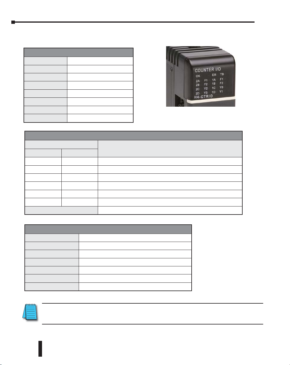
H4-CTRIO LED Indicators .........................................................................................1–12
T1H-CTRIO LED Indicators.......................................................................................1–13
Overview, How it Works as Part of the Control System .........................................1–14
CTRIO(2) Module Work Flow Diagram ...................................................................1–17
1
1
1
Page 13

Chapter 1: Introduction to the CTRIO & CTRIO2 Modules
Introduction
The Purpose of this Manual
This manual is intended as a help for the user to install, program, and maintain the CTRIO(2)
module in their system. This manual contains important information for personnel who
will install the CTRIO(2) high-speed counter module as well as for the PLC programmer.
This manual will provide all the information needed for the novice and seasoned automation
professional alike to start and keep your system up and running.
Online Help Files and Other Documentation
Regardless of the platform you are using, the programming software needed for the CTRIO(2)
modules is available as a download from our website.
http://www.aboutplcs.com/
Each programming software includes searchable online help topics covering all aspects of the
software, instruction set, module setup, and communications.
Technical Support
We strive to make our manuals the best in the industry. We rely on your feedback to let us
know if we are reaching our goal. If you cannot find the solution to your particular application,
or, if for any reason you need technical assistance, please call us at:
1-770–844–4200
Our technical support group will work with you to answer your questions. They are available
Monday through Friday from 9:00 A.M. to 6:00 P.M. Eastern Time. We also encourage you
to visit our web site where you can find information about our company and specific technical
information about a wide array of our products, www.automationdirect.com.
1–2
Counter I/O User Manual, 3rd Ed., Rev. E
Page 14

Conventions Used
DL
DL
Win
NOTE: When you see the “note pad” icon in the left-hand margin, the paragraph to its immediate right will be
a special note. Notes represent information that may make your work quicker or more efficient. The word
NOTE in boldface will mark the beginning of the text.
WARNING! When you see the “exclamation point” icon in the left-hand margin, the paragraph to its
immediate right will be a warning. This information could prevent injury, loss of property, or even
death in extreme cases. Any warning in this manual should be regarded as critical information that
should be read in its entirety. The word WARNING in boldface will mark the beginning of the text.
Chapter 1: Introduction to the CTRIO & CTRIO2 Modules
Key Topics for Each Chapter
The beginning of each chapter will list the key topics that
can be found in that chapter.
Getting Started!
In This Chapter...
.............................................................................1-2
Introduction
About Getting Started!
Supplemental Manuals and Other Help
.............................................................................1-2
Technical Support
....................................................................1-3Conventions Used
CHAPTER
....................................................................1-2Purpose of this Manual
......................................................................1-2
............................................1-2
Icons
CTRIO(2) modules are available for several hardware platforms, including DL05/06,
DL205, DL405 and Terminator. Among these four hardware platforms, there are a variety
of CPUs that can occupy the CPU slot, including, Do-more, DirectLOGIC or WinPLC.
There are also several communication interface modules that could occupy the
CPU slot, including EBCs, Modbus, DeviceNet or Profibus.
Throughout this manual, a set of icons (on right) is used to designate which
hardware platform a topic applies to, based on what module is in the CPU slot.
Icon Legend:
Do-more icon- Topic is applicable when CTRIO(2) is used with a Do-more CPU or
DM
in a slave on a Do-more CPU’s Ethernet I/O network.
DirectLOGIC icon- Topic is applicable when CTRIO(2) is used with a DirectLOGIC
DL
CPU.
WinPLC icon- Topic is applicable when CTRIO(2) is used with a WinPLC CPU.
Win
Network Interface icon- Topic is applicable when CTRIO(2) is used with any of the
NI
network interfaces: EBC (see Do-more icon instead if EBC is a slave on Do-more
Ethernet I/O network) DeviceNet, Profibus or Modbus.
1
DM
DL
Win
NI
Counter I/O User Manual, 3rd Ed., Rev. E.
1–3
Page 15
Chapter 1: Introduction to the CTRIO & CTRIO2 Modules
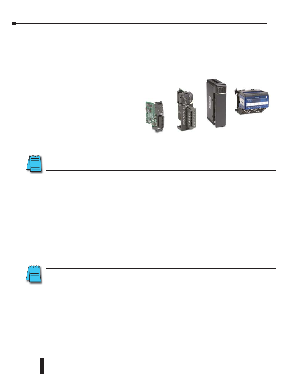
CTRIO and CTRIO2 Module Overview
A CTRIO(2) module is a programmable motion co-processor capable of accepting a variety
of encoder or discrete sensor inputs, accepting commands from the CPU, natively executing
simple control algorithms, and generating a variety of pulse-type motion control signals or
discrete actuator outputs. A CTRIO can be used for a wide variety of basic motion tasks.
Most commonly, a CTRIO module is
used to:
• Track an encoder
• Calculate rate from an encoder
• Execute homing routines
• Generate simple motion profiles
• Send pulse train control signals
to a stepper or servo amplifier
• Precisely fire a discrete output based on the position read from an encoder
NOTE: The T1H-CTRIO(2) is only supported by the T1H-EBC, T1H-EBC100 and T1H-PBC (Retired 08/20).
H0-CTRIO(2)
Available Functions
The various functions available in a CTRIO(2) module are enumerated in the following text.
There are however, limitations and dependencies to keep in mind.
• An H0-CTRIO(2) module has 4 input points on its single channel. The H2-CTRIO(2)
modules have 8 input points split between two channels. Although each channel of a
CTRIO(2) module has four input points, a channel may have only two counters/quad
counters defined. The counter/quad counter inputs appear as Function 1 and Function 2
in CTRIO Workbench.
• Some functions rely on another function being enabled. For example, scaling
cannot be selected until other inputs have been configured as a counter
or quad counter. The dependencies are enforced by CTRIO Workbench
software to ensure that an invalid configuration cannot be created.
H2-CTRIO(2)
H4-CTRIO
T1H-CTRIO(2)
1–4
If a function cannot be found in CTRIO Workbench, try enabling the function(s) on which it might
depend.
Inputs:
Input types accepted:
• Quadrature encoder with AB or ABZ
• Counter (tachometer)
• Discrete (photo eye, limit switch, Z pulse, etc.)
Counter I/O User Manual, 3rd Ed., Rev. E
Page 16

Chapter 1: Introduction to the CTRIO & CTRIO2 Modules
Functions available for discrete inputs:
• Pulse catch (high-speed discrete input with programmable filter)
• Timing: edge timer (period), dual edge timer (time difference of two inputs)
• Reset counts (Z input from encoder)
• Capture counts (copy counts of one of the counter inputs to a register)
• Inhibit counting (freeze one of the counter inputs)
• Limit for pulse output functions (CTRIO2, home switch on an axis)
Scaling of timing functions or encoder inputs:
• Rate scaling (allows the CTRIO(2) to provide encoder
data to the PLC in engineering units)
• Position scaling (allows the CTRIO(2) to provide encoder
data to the PLC in engineering units)
Outputs:
Assign the output points:
• Stepper control: Step/Direction or CW/CCW
• Discrete
Pulse profiles for stepper outputs to follow:
• Dynamic Position Plus, Trapezoid Plus, Trapezoid with Limits (homing)
(CTRIO2 only and CTRIO, Workbench v2.2.0 or later required)
• Trapezoid, S-curve, Symmetrical S-curve, Dynamic Position, Dynamic Velocity
• Home Search, Free Form
Associate output functions with inputs
• Programmable Limit Switch or ‘PLS’ (CTRIO2 only and
CTRIO Workbench v2.2.0 or later required)
• Preset tables.
Unsuitable Applications
There are some applications the CTRIO(2) specifications appear to support that are not
feasible. Common applications a CTRIO(2) cannot readily handle are listed below. If in
doubt regarding your application, please contact Automationdirect Tech Support for assistance.
Closed loop control: CTRIO2 modules are capable of very basic closed loop control. However, they
do not have full functionality expected of a typical dedicated closed loop controller. Most notably,
position or velocity errors are not reported and there is no built-in error alarming.
• CTRIO modules do not support any closed loop control. Trying to use the CPU to
close the control loop will produce unacceptable results due to excessive latency.
Counter I/O User Manual, 3rd Ed., Rev. E.
1–5
Page 17

Chapter 1: Introduction to the CTRIO & CTRIO2 Modules
Coordinated motion: Some CTRIO(2) modules have enough outputs to control multiple axes,
but there is no internal mechanism to coordinate them. Axes can move simultaneously, but
not with coordination.
Follower: CTRIO(2) modules cannot support follower applications natively. Trying to use
the CPU to close the control loop will produce unacceptable results due to excessive latency.
Precise registration: There is no means for precisely timing the start of a motion profile. Motion
profiles are initiated by the controller in the base, so scan time latency of the controller is
always a factor.
Absolute encoders: A CTRIO(2) module cannot read an absolute encoder.
Mechanical contacts as counter or encoder inputs: Reliable readings are not possible using
mechanical contacts. The bounce of mechanical contacts will cause the CTRIO(2) to see
more edges than intended.
Direct connection to TTL, line driver or differential encoders: A CTRIO(2) module cannot
accept these low voltage inputs directly. These signals need to be level shifted as shown in
Chapter 3: Installation and Field Wiring.
Support Systems for the CTRIO(2) Modules
The CTRIO(2) modules are compatible with several CPU-slot interfaces. Consideration
must be given to the firmware versions of the CPU-slot interfaces to assure their compatibility
with the CTRIO(2) (See Chapter 3 for CPU/CTRIO compatibility listings). Multiple
CTRIO(2) modules can reside in the same base provided that the backplane power budget is
adequate.
1–6
Support Systems for the H0-CTRIO(2):
• DirectLOGIC 05/06 PLC systems
Support Systems for the H2-CTRIO(2):
• DirectLOGIC 205 PLC systems (D2-240, D2-250-1, D2-260, D2-262)
• DL205 WinPLC systems (H2-WPLCx-xx)
• PC-based control strategies using the H2-EBC(100) interface module
• Hx-ERM networks using the H2-EBC(100) interface module
• Profibus systems using the H2-PBC slave interface module
• Do-more PLC systems (H2-DM1, H2-DM1E); See Do-more Designer help file.
• Do-more PLC Ethernet I/O network using H2-EBC100;
See Do-more Designer help file.
Counter I/O User Manual, 3rd Ed., Rev. E
Page 18

Chapter 1: Introduction to the CTRIO & CTRIO2 Modules
Support Systems for the H4-CTRIO:
• DirectLOGIC 405 PLC systems (D4-450 OR D4-454 only)
• PC-based control strategies using the H4-EBC interface module
• Hx-ERM networks using the H4-EBC interface module
Support Systems for the T1H-CTRIO:
• PC-based control strategies using the T1H-EBC interface module
• Profibus systems using the T1H-PBC slave interface module (Discontinued 08/2020)
• Hx-ERM networks using the T1H-EBC interface module
• Do-more PLC Ethernet I/O network using T1H-EBC100
CTRIO(2) Specifications
The tables following show general and specific information associated with CTRIO modules.
Module
Module Type
Modules Per Base
I/O Points Used
Field Wiring
Connector
Internal Power
Consumption
Operating
Environment
Manufacturer
Isolation
H0-CTRIO H0-CTRIO2 H2-CTRIO H2-CTRIO2 H4-CTRIO T1H-CTRIO
None, I/O map directly in PLC memory (V-memory for DirectLOGIC PLCs and Data structures for Do-more
250mA at +5V from Base
Power Supply
(All I/O in ON State at Max
Voltage/Current)
32°F to 140°F (0°C to 60°C), Humidity (non-condensing) 5% to 95%
2500V I/O to
Logic, 1000V
among Input
Channels and
All Outputs
1500V I/O to
Logic, 1000V
among Input
Channels and
All Outputs
General
Intelligent
Limited only by power consumption
PLCs) or PC control access
Standard removable terminal block
400mA Max at +5V
from Base Power
Supply
(All I/O in ON State at
Max Voltage/Current)
Host Automation Products, LLC
2500V I/O to Logic,
1000V among Input
Channels and All
Outputs
275mA Max at +5V
from Base Power
(All I/O in ON State at
Max Voltage/Current)
1500V I/O to Logic,
1000V among Input
Channels and All
Supply
Outputs
400mA Max at +5V from
Base Power Supply
(All I/O in ON State at Max
Voltage/Current)
2500V I/O to Logic, 1000V
among Input Channels and
All Outputs
Counter I/O User Manual, 3rd Ed., Rev. E.
1–7
Page 19

Chapter 1: Introduction to the CTRIO & CTRIO2 Modules
CTRIO(2) Specifications, cont’d
CTRIO(2) Input Specifications
Module
Inputs
Minimum Pulse Width
Input Voltage Range
Maximum Voltage
Input Voltage Protection
Rated Input Current
Minimum ON Voltage
Maximum OFF Voltage
Minimum ON Current
Maximum OFF Current
OFF to ON Response
ON to OFF Response
Counter/Timer
Resource Options
Timer Range/ Resolution
Counter Range
H0-CTRIO H0-CTRIO2 H2-CTRIO H2-CTRIO2 H4-CTRIO T1H-CTRIO
4 pts. sink/
source
100kHz Max
5 µsec 0.5 µsec 5 µsec 0.5 µsec 5 µsec
Less than 3
µsec
2, (2 per single 4 input
channel); supports 1
quadrature counter max.
1X, 2X, or 4X Quadrature, Up or Down Counter, Edge Timer, Dual Edge Timer, Input Pulse Catch,
Reset, Inhibit, Capture
4 pts. sink/
source 250kHz
Max
5.0 mA (9VDC required to guarantee ON state)
Less than 0.5
µsec
4.2 billion (32 bits); 1 µsec (70 minutes)
W2.1 billion (32 bits or 31 bits + sign bit)
8 pts. sink/source
100kHz Max
9-30 VDC
30VDC
Zener Clamped at 33VDC
8mA typical, 12mA maximum
9.0 VDC
2.0 VDC
2.0 mA
Less than 3 µsec Less than 0.5 µsec Less than 3 µsec
4, (2 per each 4 input channel group); supports 2 quadrature
8 pts. sink/source
250kHz Max
counters max.
8 pts. sink/source
100kHz Max
Module
Pulse output / Discrete
outputs
Resource Options
Target Position Range
Counter I/O User Manual, 3rd Ed., Rev. E
1–8
CTRIO(2) Output Resources
H0-CTRIO H0-CTRIO2 H2-CTRIO H2-CTRIO2 H4-CTRIO T1H-CTRIO
Pulse outputs: 1 channel (2
outputs per single channel)
Discrete outputs: 2 pts.
Pulse Outputs: pulse/direction or cw/ccw; Profiles:Trapezoid, S-Curve, Symmetrical S-Curve,
Dynamic Positioning, Dynamic Velocity, Home Search, Free Form, Dynamic Positioning Plus (CTRIO2
only),Trapezoid Plus (CTRIO2 only), Trapezoid w/Limits (CTRIO2 only), Velocity Mode, Run to Limit
Mode, Run to Position Mode
Discrete Outputs: configurable for set, reset, pulse on, pulse off, toggle, reset count functions
(assigned to respond to Timer/Count input functions).
Raw Mode: Direct access to discrete outputs from user application program
W2.1 billion (32 bits or 31 bits + sign bit)
Pulse outputs: 2 channels (2 outputs per each channel)
Discrete outputs: 4 pts.
Page 20

Chapter 1: Introduction to the CTRIO & CTRIO2 Modules
CTRIO(2) Specifications, cont’d
CTRIO(2) Output Specifications
Module
Outputs
Pulse Output Control
Range
Voltage Range
Maximum Voltage
Output clamp voltage
Maximum load current
Maximum load voltage
Maximum leakage
current
Inrush current
OFF to ON response
ON to OFF Response
ON state V drop
External power supply
Overcurrent protection
Thermal shutdown
Overtemperature reset
Duty cycle range
Configurable Presets
a) single
b) multiple
H0-CTRIO H0-CTRIO2 H2-CTRIO H2-CTRIO2 H4-CTRIO T1H-CTRIO
2 pts, isolated, either both current
sourcing or both current sinking
FET Outputs: open drain and
source with floating gate drive
20Hz to 25kHz 20Hz to 250kHz 20Hz to 25kHz 20Hz to 250kHz 20Hz to 25kHz
1.0A
36VDC 33VDC 36VDC 36VDC 36VDC
5A for 20ms 1A for 10ms 5A for 20ms 2A for 10ms 5A for 20ms
15A max
a) Each output can be assigned one preset, or
b) Each output can be assigned one table of presets, one table can contain max. 128 presets,
max. predefined tables = 255
0.5 A at 23°C
0.33 A at 60°C
Less than 3 µsec Less than 1 µsec Less than 3 µsec
m 0.3 V m 0.45 V m 0.3 V
For loop power only, not required for internal module function*
15A max;
Self resetting
overcurrent
protection
1% to 99% in 1% increments (default = 50%)
4 pts, independently isolated, current sourcing or sinking
FET Outputs: open drain and source with floating gate drive
5VDC – 36VDC
36VDC
60VDC
1.0 A
100µA
Tjunction = 150°C
Tjunction = 130°C
1.0 A at 23°C,
0.5 A at 60°C
15A max
1.0 A
Counter I/O User Manual, 3rd Ed., Rev. E.
1–9
Page 21
Chapter 1: Introduction to the CTRIO & CTRIO2 Modules
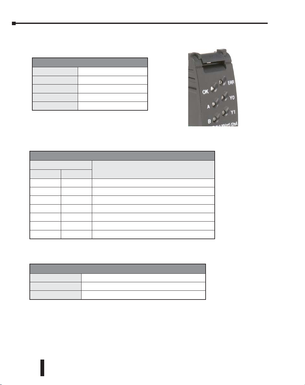
H0-CTRIO(2) LED Indicators
H0-CTRIO(2) LED Descriptions
OK
ERR
A
B
Y0 - Y1
LED Status
OK ERR
ON OFF RUN Mode
ON ON Hardware Failure
Blinking Blinking Boot Mode - Used for Field OS Upgrades
Blinking OFF Program Mode
OFF Blinking Module Self-diagnostic Failure
OFF ON Module Error Due to Watchdog Timeout
OFF OFF No Power to Module
Module OK
User Program Error
Ch1 F1 Resource State
Ch1 F2 Resource State
Output Status
H0-CTRIO(2) LED Diagnostics
Status Description
1–10
H0-CTRIO(2) LED Run Diagnostics Definitions
A
B
Y0–Y1
Blinks when Channel 1 Function 1 is counting or timing
Blinks when Channel 1 Function 2 is counting or timing
Follow actual output state; ON = output is passing current
Counter I/O User Manual, 3rd Ed., Rev. E
Page 22
Chapter 1: Introduction to the CTRIO & CTRIO2 Modules
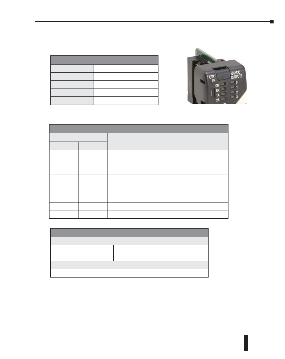
H2-CTRIO(2) LED Indicators
H2-CTRIO(2) LED Descriptions
OK
ER
1A
2A
0–3
LED Status
OK ER
ON OFF RUN Mode
ON ON
Blinking Blinking Boot Mode - Used for Field OS Upgrades
Blinking OFF Program Mode
Module OK
User Program Error
Channel 1 Status
Channel 2 Status
Output Status
H2-CTRIO(2) LED Diagnostics
Hardware Failure (H2-CTRIO)
Not Used (H2-CTRIO2)
Status Description
OFF Blinking Module Self-diagnostic Failure (Blinks may be coded by counts)
OFF ON Module Error Due to Watchdog Timeout
OFF OFF No Power to Module
H2-CTRIO(2) LED Diagnostics Definitions
1A /2A
Blinking 7 times per second Input is Configured as Counter and is Changing
Following State of Input Input is not Configured as Counter
0–3
Follow actual output state; ON = output is passing current
Counter I/O User Manual, 3rd Ed., Rev. E.
1–11
Page 23
Chapter 1: Introduction to the CTRIO & CTRIO2 Modules
H4-CTRIO LED Indicators
H4-CTRIO LED Descriptions
OK
ER
TB
1A–1D
2A–2D
(Ch1) F1–F2
(Ch2) F1–F2
Y0–Y3
LED Status
OK ER
ON OFF RUN Mode
Blinking Blinking Boot Mode - Used for Field OS Upgrades
Blinking OFF Program Mode
OFF Blinking Module Self-diagnostic Failure
OFF ON Module Error Due to Watchdog Timeout
OFF OFF No Power to Module
Module OK
User Program Error
Removed Terminal Block
Ch1A - Ch1D Input Status
Ch2A - Ch2D Input Status
Ch1 Resource State
Ch2 Resource State
Output Status
TB
H4-CTRIO LED Diagnostics
Status Description
User Terminal Block is not Properly Installed
1–12
H4-CTRIO LED Diagnostics Definition
1A–1D
2A–2D
(Ch1) F1
(Ch1) F2
(Ch2) F1
(Ch2) F2
Y0–Y3
NOTE: Due to the multiplexed design of the DL405 LED matrix, OFF state LEDs may appear to blink ON
slightly. This is to be expected and does not necessarily indicate a transient condition of the function
corresponding to the LED.
Follow actual input state / Ch1
Follow actual input state / Ch2
Blinks when Channel 1 Function 1 is counting or timing
Blinks when Channel 1 Function 2 is counting or timing
Blinks when Channel 2 Function 1 is counting or timing
Blinks when Channel 2 Function 2 is counting or timing
Follow actual output state; ON = output is passing current
Counter I/O User Manual, 3rd Ed., Rev. E
Page 24
Chapter 1: Introduction to the CTRIO & CTRIO2 Modules
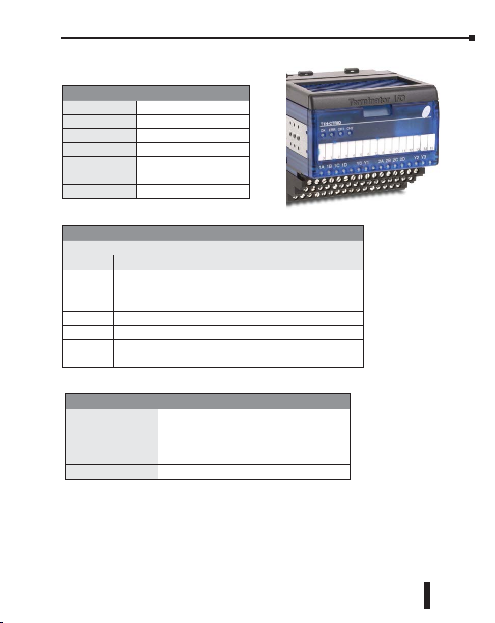
T1H-CTRIO LED Indicators
T1H-CTRIO LED Descriptions
OK
ERR
CH1
CH2
1A–1D
2A–2D
Y0–Y3
LED Status
OK ER
ON OFF RUN Mode
ON ON Hardware Failure
Blinking Blinking Boot Mode - Used for Field OS Upgrades
Blinking OFF Program Mode
OFF Blinking Module Self-diagnostic Failure
OFF ON Module Error Due to Watchdog Timeout
OFF OFF No Power to Module
Module OK
User Program Error
Channel 1 Status
Channel 2 Status
Channel 1 A-D Input Status
Channel 2 A-D Input Status
Output Status
T1H-CTRIO LED Diagnostics
Status Description
CH1
CH2
1A–1D
2A–2D
Y0–Y3
T1H-CTRIO LED Diagnostics Definitions
Blinks when Channel 1 Function 1 is counting or timing
Blinks when Channel 2 Function 1 is counting or timing
Follow actual input state / Ch1
Follow actual input state / Ch2
Follow actual output state; ON = output is passing current
Counter I/O User Manual, 3rd Ed., Rev. E.
1–13
Page 25

Chapter 1: Introduction to the CTRIO & CTRIO2 Modules
Overview, How it Works as Part of the Control System
Basic Operation
A CTRIO(2) is an intelligent co-processor module. It has to be configured using CTRIO
Workbench before it can do anything. It has its own scan time and can be in either program
or run mode.
Being an Intelligent Module means that the CTRIO(2) controls its own writes to and reads
from CPU memory. The CPU does not directly write to or read from the CTRIO(2). The
CTRIO(2) will write to and read from the addresses designated in I/O Map. Understanding this
relationship is helpful to understanding the timing (interlocking) requirements for performing
operations that require the PLC to make changes to the CTRIO(2) from ladder logic.
Understand that the CPU can only make requests to the CTRIO(2) by turning on specific bits
and placing appropriate data in its own memory. The CTRIO(2) reads the data from those
addresses in the CPU and then acts on it. The CTRIO(2) provides feedback to the CPU by
writing to other CPU memory.
NOTE: A CTRIO(2) is an Intelligent Module. It directly writes to and reads from CPU memory. The CPU
cannot directly write to or read from CTRIO(2) memory. The CTRIO(2) writes to and reads from the
addresses designated in I/O Map.
After being configured by CTRIO Workbench, a CTRIO(2) module is ready to be placed in
run mode. Basic input functions of the CTRIO(2) run automatically, such as reporting counts
on an input channel. Output functions are initiated by the controller (the PLC CPU). The
controller uses Command Codes to control the output functions of the CTRIO(2), such as
executing a pulse profile on an output, or loading or editing a preset table. IBox instructions
are macros that use Command Codes. Command Codes and the instructions on their use are
found later in this manual.
1–14
Counter I/O User Manual, 3rd Ed., Rev. E
Page 26
Chapter 1: Introduction to the CTRIO & CTRIO2 Modules
CTRIO Workbench
CTRIO Workbench is the utility used to configure the many functions available for a
CTRIO(2) module.
CTRIO Workbench communicates with a CTRIO(2) module through the base controller to
configure the CTRIO(2). The configuration is stored in the CTRIO(2) and also stored in a
file on your computer. Configuring the CTRIO(2) is a separate process from programming
the base controller.
The CTRIO Workbench
configuration contains these basic
parameters:
• Assignments of the input and
output points
• Scaling of inputs (optional)
• Preset Table setup (optional)
• Programmable Limit Switch setup
(CTRIO(2), optional)
• Mapping to CPU memory
NOTE: The CTRIO(2) must be configured in program mode, and the memory must be mapped prior to
program execution.
Counter I/O User Manual, 3rd Ed., Rev. E.
1–15
Page 27

Chapter 1: Introduction to the CTRIO & CTRIO2 Modules
Command Codes
Command Codes are the instructions available to the CPU to tell the CTRIO what to do. A list
of the Command Codes with a brief description of their function are shown in the table below.
Command Code and Parameter Definitions
Command
Load Table from ROM 10
Load Table from ROM 10
Load Table from ROM 10
Velocity Mode 20
Run to Limit Mode 21
Run to Position Mode 22
* A value of 0 will generate a duty cycle of 50%
Code
(Hex/BCD)
Those fields separated by an “&” indicate a code with different definitions for each byte
(high byte and low byte). For example, to enter the Pulse Output to Limit command, set the
high byte of the Word Parameter 2 to the edge you wish to terminate the output pulses (see
definition following), and set the low byte to the desired duty cycle.
In order to process a command, first the program must load the Command Code and required
DWord, Word, and bit parameters. Then the program should turn ON the Process Command
bit and look for the CTRIO(2) module to acknowledge the command with the Command
Complete bit. Finally, the program should reset the Process Command bit and set the Enable
Output bit when appropriate. If the Command Error bit is received, the CTRIO(2) module
was unable to process the command due to an illegal value in either the Command Code or
parameter files.
DWord and Word values for pulse outputs are unsigned integers (Parameter 3 on some profiles
can be signed).
Word Parameter 1
(decimal)
Trapezoid or S-curve
Symmetrical S-Curve
Home Search
File Number
Dynamic Positioning
File Number
Dynamic Velocity
File Number
Run Frequency
(CTRIO: 20Hz - 25KHz
CTRIO2: 20Hz - 64KHz)
Run Frequency
(CTRIO: 20Hz - 25KHz
CTRIO2: 20Hz - 64KHz)
Run Frequency
(CTRIO: 20Hz - 25KHz
CTRIO2: 20Hz - 64KHz)
Word Parameter 2 DWord Parameter 3
- -
- Target Position (decimal)
- Target Velocity (decimal)
Duty Cycle (0 to 99)*
(decimal)
Edge &
Duty Cycle (0 to 99)*
(Hex/BCD)
Compare Function &
Duty Cycle (0 to 99)*
(Hex/BCD)
Number of Pulses (BCD/Hex)
-
Desired Input Function Value
(decimal)
1–16
Counter I/O User Manual, 3rd Ed., Rev. E
Page 28
Chapter 1: Introduction to the CTRIO & CTRIO2 Modules
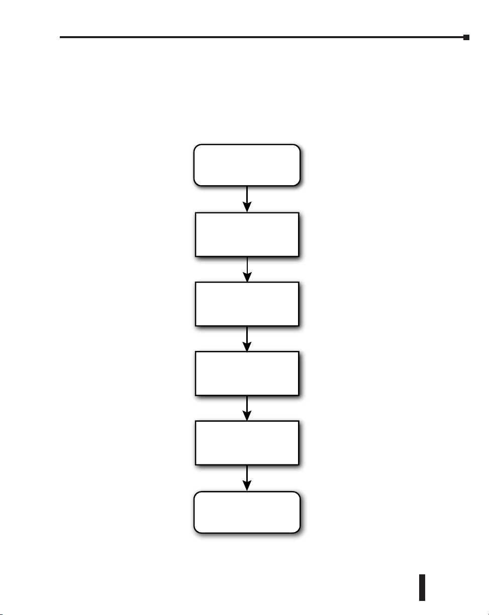
CTRIO(2) Module Work Flow Diagram
The following workflow diagram shows the steps needed, with their associated chapters in this
manual, to install and setup a CTRIO(2) module into your system.
DirectLOGIC, WinPLC or EBC
Install CTRIO
Chapter 3
Configure CTRIO using
CTRIO Workbench
Chapter 4, 5 & 6
Testing Wiring using
CTRIO Workbench’s
Monitor I/O Dialog
Chapter 7, 8 & 9
Map Memory
in Controller
Chapter 10, Appx A
Runtime Table Functions
Chapter 11
System Functions
Appendix B
Counter I/O User Manual, 3rd Ed., Rev. E.
1–17
Page 29

Chapter
Chapter
GettinG Started,
BaSicS and exampleS
In This Chapter...
Overview .................................................................................................................... 2-2
Basic Motion Functions, Summary of Examples ....................................................... 2-2
Detailed Example: Configure and Test a Quadrature Input ................................... 2-7
Detailed Example: Configure and Test a Pulse Output w/Trapezoidal Profile ..... 2-16
Flow Chart Example: Configure and Test a Pulse Output w/Trapezoidal Profile 2-27
Chapter
2
2
2
Page 30

Chapter 2: Getting Started
Overview
This chapter is intended for the newcomer and includes brief descriptions of how to implement
some common motion control solutions using CTRIO(2). The descriptions should give the
newcomer a good understanding of what basic steps are required to implement the function.
With this general understanding, specifics on each step can be sought out later in the manual.
Later in the chapter, two detailed examples walk the user through what is required to implement
two of the most common functions, reading a quadrature encoder and generating a trapezoidal
profile.
Basic Motion Functions, Summary of Examples
Get Position Using an Encoder
To read the position of an encoder, follow these basic steps in CTRIO Workbench:
1: Config I/O - Configure the appropriate inputs to recognize the encoder.
2: Optionally set up position scaling if desired.
3: Use I/O Map to map the CTRIO(2) to the controller’s memory and print the I/O Map
Report.
4: Download the configuration to the CTRIO(2) module and put the CTRIO(2) in Run.
5: Finally, go online with the controller to check that the encoder counts are appearing in
the mapped address.
2-2
Get Rate Using an Encoder
To read the rate of an encoder, follow these basic steps in CTRIO Workbench:
1: Select Config I/O under Module Configuration to Configure the appropriate inputs to
recognize the encoder.
2: Set scaling to rate - Scaling Wizard ruler button:
3: Choose the conversion parameters.
4: Use the Rate Scaling Calculator to verify the chosen settings.
5: Use I/O Map to map the CTRIO(2) to the controller’s memory and print the I/O Map
Report.
6: Download the configuration to the CTRIO(2) module and put the CTRIO(2) in Run.
7: Go online with the controller to check that encoder rate is appearing in the mapped
address.
Measure Timing Between Pulse Edges
To measure the time between edges of a pulse in CTRIO Workbench:
1: Select Config I/O under Module Configuration to configure an input as Edge Timer,
selecting the appropriate options (free-run is suggested for testing since it does not
require interaction from the controller to function).
2: Optionally, set up scaling if desired.
Counter I/O User Manual, 3rd Ed., Rev. E
Page 31

Chapter 2: Getting Started
3: Select I/O Map to map the CTRIO(2) to the controller memory and print the I/O
Map Report.4: Download the configuration to the CTRIO(2) module and put the
CTRIO(2) in Run.
5: Go online with the controller to check that pulse measurements are appearing in the
mapped address.
Output Position Pulses
Several options are available for generating pulses for controlling drives, steppers, servos, etc..
Some options are only available on a CTRIO2 module, as noted. Those only available on
CTRIO2 tend to be more versatile and are preferred. Shaded cells highlight the advantaged
attributes.
Options Position Source
Dynamic
Positioning Plus
Trapezoid Plus
Dynamic
Positioning
S-Curve
Symmetrical
S-Curve
Trapezoid
Free Form
From controller Ye s
From controller Ye s
From controller No
Hard-coded in
pulse prole
Hard-coded in
pulse prole
Hard-coded in
pulse prole
Hard-coded in
pulse prole
Change
target
position on
the y
No
No
No
No None 65kHz
Accel / Decel
ramps
Specify
separately
Specify
separately
One setting
for both
Specify
separately
One setting
for both
Specify
separately
Maximum
pulse rate
250kHz Yes Ye s
250kHz Yes Ye s
65kHz
65kHz
65kHz
65kHz
1
1
1
1
1
Encoder
Feedback
Possible
No No
No No
No No
No No
No No
Requires
CTRIO2
The following example uses Dynamic Positioning Plus on a CTRIO2. To use Dynamic
1
The older CTRIO outputs can only achieve 25kHz maximum. CTRIO2 outputs are limited to 65kHz when using these profiles.
Positioning Plus to send output pulses to an amplifier (without encoder feedback), follow these
basic steps in CTRIO Workbench:
1: Select Config I/O under Module Configuration to configure the outputs to provide
pulses appropriate for the amplifier.
2: Select Pulse Profiles at bottom of dialog box.
3: Optionally, give the profile a name.
4: Select Dynamic Positioning Plus and choose the Frequency Settings appropriate for
the motor and system.
5: Note the File Number assigned.
6: Use I/O Map to map the CTRIO(2) to the controller’s memory and print the I/O
Map Report.
7: Download the configuration to the CTRIO(2) module and put the CTRIO(2) in
Run.
Counter I/O User Manual, 3rd Ed., Rev. E
2-3
Page 32

Chapter 2: Getting Started
Home an Output
There are several available options for finding home on an output. If using a CTRIO2, Trapezoid
with Limits profile will nearly always be the best option. The following example uses Trapezoid
with Limits profile on a CTRIO2.
The table below shows a comparison of the available methods of homing an output with a
CTRIO(2) module. Shaded cells highlight the advantaged attributes.
To home an output with one or more limit switches, follow these basic steps in CTRIO Workbench.
Prole
Trapezoid
with Limits
Home
Search*
Run to Limit
*Home Search allows you to select 2nd limit or different speed.
Accel
and Decel
Ramps
Yes Ye s No Ye s Yes Yes Yes
No No* No Yes No Yes No
No No Ye s No No No No
1: Select Config I/O to configure the outputs to provide pulses appropriate for the chosen
amplifier.
2: Configure one or more inputs as Limit Out n where n is the output configured above.
3: Select Pulse Profiles at bottom of dialog box.
4: Select Add to create a new profile, or select an existing named profile.
5: Optionally, give the profile a name (defaults to “File 1-” upon closing dialog box).
6: Select Trapezoid profile with Limits.
7: Configure the Decel and Stop Triggers.
8: Choose the Frequency Settings appropriate for the motor and system.
9: Note the File Number assigned.
10: Use I/O Map to map the CTRIO(2) to the controller’s memory and print the I/O
Map Report.
11: Download the configuration to the CTRIO(2) module and put the CTRIO(2) in Run.
Creep to
second
limit or
position
Change
velocity
manually
on the y
Multiple
limits or
triggers
on a
single
home
search
Single
input can
act as
multiple
triggers
Prole
dened
in CTRIO
Workbench
Requires
CTRIO2
2-4
Counter I/O User Manual, 3rd Ed., Rev. E
Page 33

NOTE: The following steps are generic. Details are available in the manual.
In the controller:
1: Command the CTRIO2 to load the Trapezoid with Limits profile (by file number)
for the appropriate output.
2: Specify the direction (CW/CCW) to seek home.
3: Set the appropriate CTRIO2 Enable Output bit.
4: The controller can monitor status bits for visibility into the CTRIO’s progress.
Output PWM Pulses1
To generate PWM outputs, follow these basic steps in CTRIO Workbench.
1: Config I/O - Configure an output for Step/Direction, the step output will have the
PWM signal.
2: Use I/O Map to map the CTRIO(2) to the controller’s memory and print the I/O
Map Report.
3: Download the configuration to the CTRIO(2) module and put the CTRIO(2) in
Run.
4: In the controller - (Note: These steps are generic. Details are available in the
DirectLOGIC manual).
5: Set the command code for Velocity Mode.
6: Set Parameter 1 (Frequency).
7: Set Parameter 2 (Duty Cycle) from 1 to 99.
8: Set Parameter 3 (Number of Output Pulses) to FFFF FFFF for unlimited.
9: Set the appropriate CTRIO2 Enable Output bit to start pulses.
10: To stop pulses, reset the appropriate Enable Output bit.
11: To change the Duty Cycle, need source.
Chapter 2: Getting Started
Programmable Limit Switch or Preset Table
To control one of the CTRIO(2) outputs with a PLS or Preset Table that monitors an encoder
input, follow these basic steps in CTRIO Workbench.
1: Config I/O - Configure the appropriate inputs to recognize the encoder, noting the
Channel and Function numbers assigned.
2: Optionally set up scaling if desired.
3: Configure an output as Discrete on Ch_/Fn_, using the Channel and Function
numbers from the encoder input.
4: Discrete Tables…
Counter I/O User Manual, 3rd Ed., Rev. E
2-5
Page 34

Chapter 2: Getting Started
5: Add Preset Table or Add PLS Table
6: Optionally give the table a name.
7: Configure the table for the desired behavior.
8: Scales will be available if scaling was defined for the input.
9: Note the File Number assigned.
10: Use I/O Map to map the CTRIO(2) to the controller’s memory and print the I/O
Map Report.
11: Download the configuration to the CTRIO(2) module and put the CTRIO(2) in
Run.
NOTE: The following steps are generic. Details are available in the manual.
In the controller:
1: Command the CTRIO2 to load the Table by its file number
2: Set the appropriate CTRIO(2) Enable Output bit
3: The controller can monitor status bits for visibility into the CTRIO’s progress
1
Output Discrete On/Off from Ladder
The output points on a CTRIO(2) can be turned on and off from ladder, called Raw control.
Keep in mind that they will not react as quickly as the outputs of a standard discrete output
module since there is also the scan time of the CTRIO(2) that can add latency. To simply turn
the output of a CTRIO(2) on or off from ladder, follow these basic steps in CTRIO Workbench:
1: Config I/O - Configure any outputs to be controlled as Raw.
2: Use I/O Map to map the CTRIO(2) to the controller’s memory and print the I/O
Map Report.
3: Download the configuration to the CTRIO(2) module and put the CTRIO(2) in
Run.
NOTE: These steps are generic. Details are available later in the manual.
In the controller:
1: Set the appropriate CTRIO(2) Enable Output bit.
2: The controller can monitor status bits for visibility into the CTRIO’s progress.
1. PLS Tables are only available when using CTRIO2 hardware.
Counter I/O User Manual, 3rd Ed., Rev. E
2-6
Page 35

Chapter 2: Getting Started
Detailed Example: Configure and Test a Quadrature Input
This example walks through the steps required to get the counts from a quadrature encoder
connected to a CTRIO(2) to appear in the CPU memory of a DirectLOGIC PLC. The
example uses DL06 hardware, but is applicable to DL05 and DL205 hardware as well.
The Basic Steps
1: Gather and connect the hardware (not covered here).
2: Launch CTRIO Workbench.
3: Use Config I/O to configure the appropriate inputs to recognize the encoder.
4: Use I/O Map to map the CTRIO(2) to the controller’s memory and print the I/O
Map Report.
5: Write the configuration to the CTRIO(2) module and put the CTRIO(2) in Run.
6: Use Monitor I/O to verify the encoder movement is being interpreted by the
CTRIO(2) properly.
7: Launch DirectSOFT and use Data View to check that position data is appearing in
the mapped addresses .
Equipment Needed
DirectLOGIC 06 base and H0-CTRIO2 installed in slot 41. A quadrature encoder properly
powered and connected to the H0-CTRIO2.
Launch CTRIO Workbench
When using CTRIO Workbench with a DirectLOGIC CPU and the latest version of DirectSOFT,
the best way to launch it is from DSLaunch. DSLaunch is installed when installing DirectSOFT.
Open DSLaunch.exe.
Click “CTRIO WB 2 – DirectLOGIC PLC” to open CTRIO Workbench. The Select
1. If using DirectLOGIC 205 hardware, the CTRIO(2) cannot be installed directly next to the CPU slot.
Counter I/O User Manual, 3rd Ed., Rev. E
2-7
Page 36
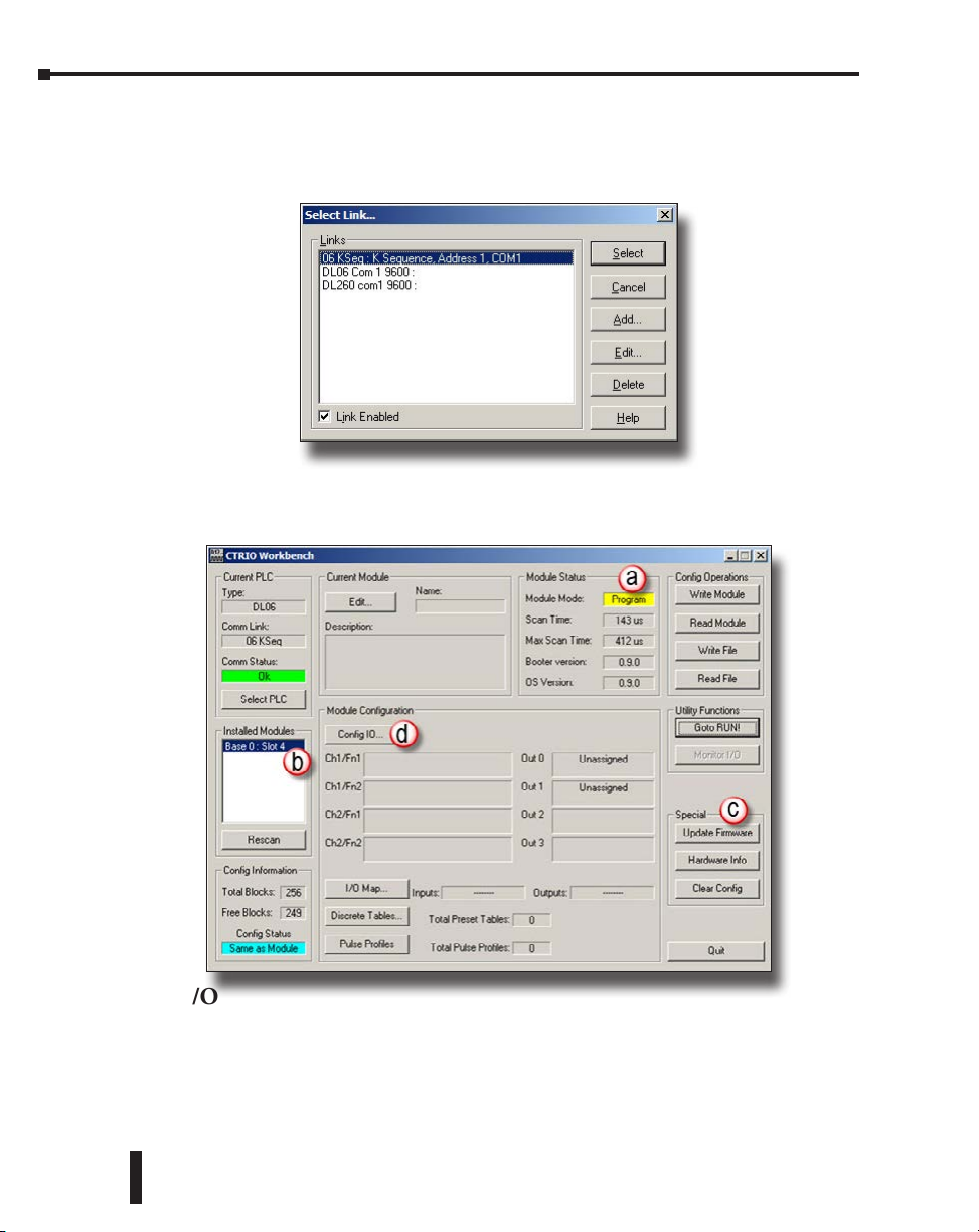
Chapter 2: Getting Started
Link… dialog box appears. Select the appropriate PLC communication link to use. If it does
not appear in the list, check power and the communications cable or, create a new link by
clicking on ‘Add’.
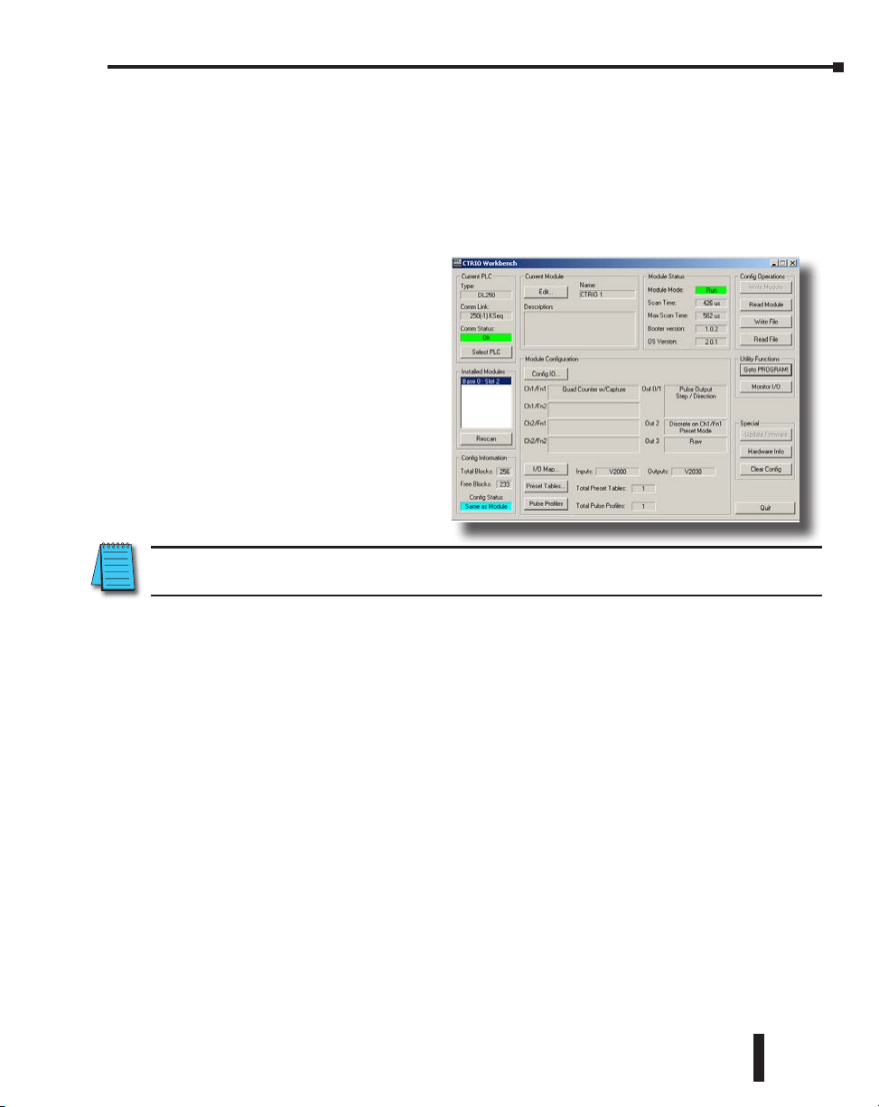
Once connected, CTRIO Workbench will look like the one below. The H0-CTRIO2 shown
is new and has no configuration. It is in Program mode (a). It is installed in slot 4 (b). Now
is a good time to check the firmware version and make sure it’s current (c).
2-8
Config I/O
For this example, it is only necessary to configure the inputs of the H0-CTRIO2 to recognize
a quadrature encoder. Click Config I/O (d) command box.
Counter I/O User Manual, 3rd Ed., Rev. E
Page 37

Chapter 2: Getting Started
The Configure I/O panel is divided into two sections. One section is for Channel 1 Inputs
(A-D) and the other section is for the Outputs (0-3). If working with an H2-CTRIO2, there
would also be a tab for Channel 2.
Within Channel 1, note there are Function 1 (a) and Function 2 (b). Each Channel on a
CTRIO(2) module may have up to two Functions assigned.
On Channel 1, select Quad Counter (c). This tells the CTRIO(2) to expect quadrature signals
on Channel 1 Inputs A and automatically, B.
NOTE: Many other defaults change when a selection is made:
• The option for Input B to be a simple counter disappears and it is
assigned as Slave to A and can no longer be directly changed.
• Some options for Input C disappear and a new option appears.
• Channel 1 Function 1 area displays Quadrature Counter and
offers multiple options that apply to that counter input.
• New options for the Outputs appear that reference Ch1/
Fn1, the quadrature input function created.
Counter I/O User Manual, 3rd Ed., Rev. E
2-9
Page 38
Chapter 2: Getting Started
NOTE: This automatic reconfiguring of available options is an important feature of CTRIO Workbench.
The primary benefit is that it prevents the user from selecting options that will not work together. It is
not possible to create an invalid configuration. However, keep this feature in mind when going about
configuring a CTRIO(2). If a function cannot be found, it’s likely that some dependency has not yet been
enabled, or a feature that has been enabled is consuming an exclusive resource the desired feature also
requires.
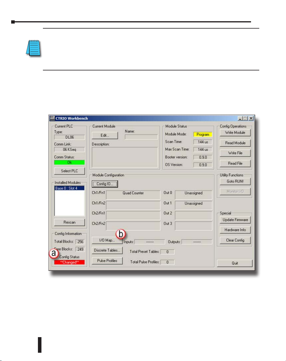
Click OK to keep the changes and go back to the CTRIO Workbench home screen.
On the home screen, note the indication in the lower left (a), Config Status **Changed**. This
indicates that the configuration in Workbench does not match what was read from the module.
Before the new configuration is written to the module, there is one other thing that must be
done. Click I/O Map (b). This brings up the I/O Map dialog box.
2-10
Counter I/O User Manual, 3rd Ed., Rev. E
Page 39

Chapter 2: Getting Started
I/O Map
Depending on the configuration, the CTRIO(2) will have some number of variables to pass
back and forth to the CPU. The data does not fit in the normal structure that most I/O
modules use. Instead, the CTRIO(2) is able to write to and read from any CPU memory
specified. In this panel, map the variables into CPU memory.
Be careful to map memory addresses that will not be used for any other purpose.
In Map Display Mode (a), select “PLC - Mapped Addresses (2 ranges)” mode.
In the Input Map box (b) point the CTRIO(2) where to write input data to the PLC memory.
Click “Enable Write to PLC” and type in an address for “Starting V address for inputs”. V2000
is used here as the starting address.
Counter I/O User Manual, 3rd Ed., Rev. E
2-11
Page 40

Chapter 2: Getting Started
Note how entering the address changes the display under (a) Input Function tab, “Ch1/Fn1
– Quad Counter Input Data”. The two variables displayed are Current Count (32 bit integer
that gets mapped to V2000-2001) and AT Reset Value (a bit that gets mapped to the second
bit of V2020, or V2020.1). Clicking on the (b) “System Functions” tab reveals ten more status
bit variables that were also mapped. Each of these variables provides status information to the
CPU.
The “Output Map”(c) section tells the CTRIO(2) where to read variables out of the CPU and
to be able to reset the counter from the ladder logic program.
2-12
In this particular example, it is not necessary for
the CTRIO(2) to read any addresses from the
CPU. As configured, once the CTRIO(2) is in
run mode, it will constantly report the counts
to the CPU via the Current Count variable. As
can be seen in the previous two images, if no
addresses are specified in “Output Map”, there
will be no way for the CTRIO(2) to get to the
Reset or Process SysCmd bits, which are not needed
here.
Counter I/O User Manual, 3rd Ed., Rev. E
Page 41

Chapter 2: Getting Started
Once the I/O Map is set up, it is best to print the “Memory Map Report”. Click on the
“Report…” button to access the dialog below. Click on “Print”. Creating this hard copy
provides a critical reference to have in hand while writing the control program. The report
can also be saved to disk as a “.txt” file by clicking on “Save” and giving it a unique name.
When finished, close this dialog then click OK on the I/O Map dialog to return to the CTRIO
Workbench home screen.
Download the Configuration
Now that the configuration has been defined, press “Write File” (a) to save a copy of the
configuration to disk. It will save as a “.cwb” file that should be kept together with the other
project files and documents.
Note that the “Config Status” (b) changes to Same as File,
indicating that the file on disk and the file in CTRIO workbench
are identical.
Counter I/O User Manual, 3rd Ed., Rev. E
2-13
Page 42
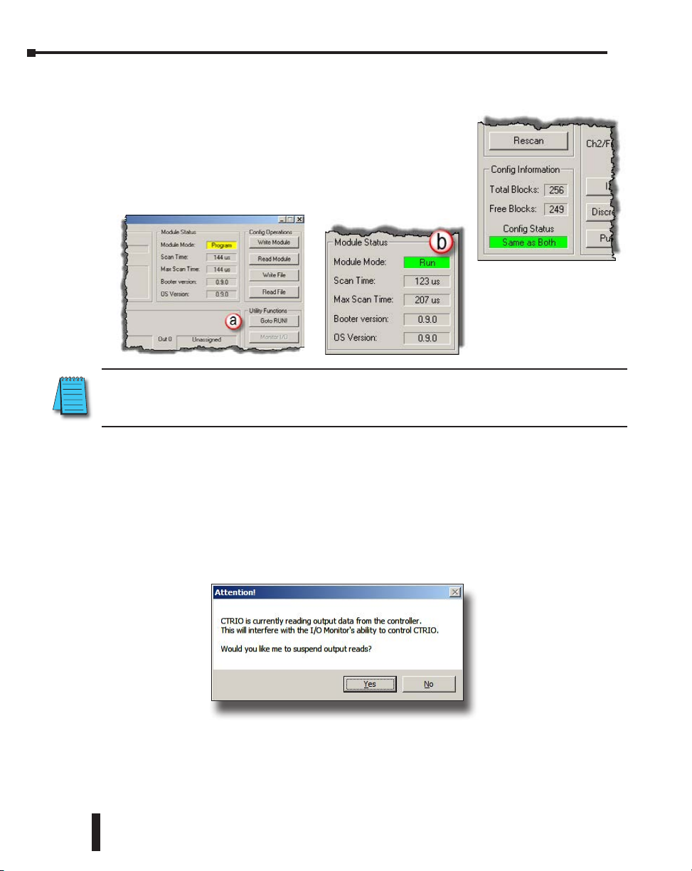
Chapter 2: Getting Started
Once saved, click “Write Module” to write the file to the CTRIO(2) module. The Config
Status changes to Same as Both, indicating that the file on disk, the file in CTRIO workbench
and the file in the CTRIO(2) module are identical.
At this point, the CTRIO(2) module is still in Program mode,
doing nothing. Click “Goto RUN!” (a) to have the module begin
execution. The module will begin interpreting input pulses as
a quadrature input and writing the resulting counts to V2000-
2001. Note (b) “Module Mode” changes to Run.
NOTE: It is only necessary to manually switch the CTRIO(2) into Run or Program during testing. During
normal operation, the CTRIO(2) follows changes in the mode of the CPU. If the CPU goes to Stop, the
CTRIO(2) goes to Program. If the CPU goes to Run, the CTRIO(2) goes to Run.
Monitor I/O
Before jumping over to using the CPU to work with the CTRIO(2) module, there is a very
convenient way to verify everything is working as expected from within CTRIO Workbench.
Click Monitor I/O. The following prompt may appear, asking whether the system should
suspend output reads. Output reads are what the CTRIO(2) does to know what the CPU
is telling it to do. Suspending them just means that the CTRIO(2) should temporarily stop
taking commands from the CPU. The CTRIO(2) will be controlled from the Monitor I/O
panel, so answer Yes.
2-14
The CTRIO(2) stops reading addresses from the CPU and Monitor I/O opens.
Counter I/O User Manual, 3rd Ed., Rev. E
Page 43

Chapter 2: Getting Started
This dialog box displays a variety of important I/O information at a glance. The raw state of
each discrete input point is indicated under Input Status (a). This is very handy for quickly
checking the encoder wiring.
Give the encoder a twist to verify that Current Counts (b) follows the movement and At Reset
Value (c) goes low. If no inputs ever appear On, check the encoder wiring carefully. If the text
Quad Counter and Current Count do not appear, make sure the configuration was sent to the
CTRIO(2) module.
The other tabs, not used in this example, have some very useful tools for monitoring and testing
Output Functions (d) as well as System Functions (e).
Counter I/O User Manual, 3rd Ed., Rev. E
2-15
Page 44

Chapter 2: Getting Started
Detailed Example: Configure and Test a Pulse Output
with a Trapezoidal Profile
This example walks through the steps required to use a DirectLOGIC PLC to generate a
trapezoidal profile on an output channel of a CTRIO(2). The example uses DL06 hardware,
but is applicable to DL05, DL205 and DL405 hardware as well.
The Basic Steps
1: Gather and connect the hardware (not covered here).
2: Launch CTRIO Workbench.
3: Use Config I/O to configure the appropriate outputs to generate pulses appropriate for
the amplifier in use.
4: Use I/O Map to map the CTRIO(2) to the controller’s memory and print the I/O
Map Report.
5: Use Pulse Profile Tables to create a Trapezoid Plus Pulse Profile and select its Frequency
Settings.
6: Download the configuration to the CTRIO(2) module and put the CTRIO(2) in
Run.
7: Use Monitor I/O to manually generate an output profile to make sure the
configuration and hardware connections are correct.
8: Launch DirectSOFT and use Data View to manually generate an output profile.
Equipment Needed
DirectLOGIC 06 base and H0-CTRIO2 installed in slot 21. A stepper amplifier and motor,
properly powered and connected to the H0-CTRIO2. Alternately, the output activity can be
monitored in Data View or in Monitor I/O in CTRIO Workbench.
Launch CTRIO Workbench
1
If using DirectLOGIC 205 hardware, the CTRIO(2) cannot be installed directly next to the CPU slot.
Counter I/O User Manual, 3rd Ed., Rev. E
2-16
Page 45
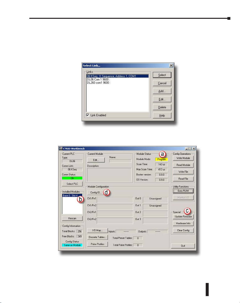
Chapter 2: Getting Started
The best way to launch CTRIO Workbench is from DSLaunch. DSLaunch is installed as part
of a DirectSOFT install. Open DSLaunch.exe.
Click CTRIO WB 2 – DirectLOGIC PLC to open CTRIO Workbench. The Select Link…
dialog appears asking which PLC communication link to use. Select the appropriate PLC.
If it does not appear in the list, check power and the communications cable; or, create a new
link.
Once connected, CTRIO Workbench will look like the one below. The H0-CTRIO2 shown
is new and has no configuration. It is in Program mode (a). It is installed in slot 4 (b). Now
is a good time to check the firmware version and make sure it’s current (c).
Config I/O
For this example, it is only necessary to configure the outputs of the H0-CTRIO2 to generate
pulses for the connected stepper amplifier. Click “Config I/O”(d) command box.
Counter I/O User Manual, 3rd Ed., Rev. E
2-17
Page 46
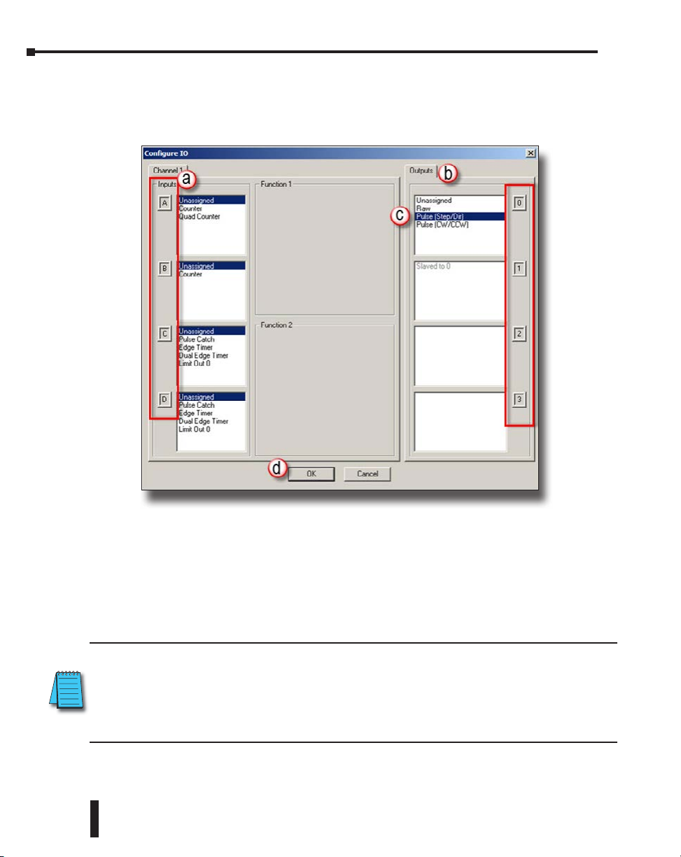
Chapter 2: Getting Started
The Configure I/O panel is divided into two sections. One section (a) is for Channel 1 Inputs
(A-D) and the other section (b) is for the Outputs (0-3). If working with an H2-CTRIO2,
there would also be a tab for Channel 2. Within Channel 1, note there are Function 1 and
Function 2. Each Channel on a CTRIO(2) module may have up to two Functions assigned.
2-18
On Output 1 (c), select the appropriate format for the step amplifier. The example uses Pulse
(Step/Dir), (reference here to Output 0). This tells the CTRIO(2) that Output 0 will be used
as the step signal. Automatically, Output 1 is assigned as the Direction signal.
NOTE: Many other defaults change when a selection is made:
• Options for Output 1 to be Raw disappears and it is assigned
as Slaved to 0 and can no longer be directly changed.
• An option is added to Channel 1 Inputs C and D for them to be Limit Out 0.
NOTE: This automatic reconfiguring of available options is an important feature of CTRIO Workbench.
The primary benefit is that it prevents the user from selecting options that will not work together. It is
not possible to create an invalid configuration. However, keep this feature in mind when going about
configuring a CTRIO(2). If a function cannot be found, it’s likely that some dependency has not yet been
enabled, or a feature that has been enabled is consuming an exclusive resource the desired feature also
requires.
Click “OK (d) to keep the changes and go back to the CTRIO Workbench home screen.
Counter I/O User Manual, 3rd Ed., Rev. E
Page 47

Chapter 2: Getting Started
A dialog box appears warning that I/O has not yet been mapped to PLC memory. This
warning only occurs if mapping the memory is required. Click “OK, let’s map them now”
to open the I/O Map dialog box (also accessible by clicking on “I/O Map” from the CTRIO
Workbench home screen).
I/O Map
Depending on the configuration, the CTRIO(2) will have some number of variables to pass
back and forth to the CPU. The data does not fit in the normal structure that most I/O
modules use. Instead, the CTRIO(2) is able to write to and read from any CPU memory
specified. In this panel, map the variables into CPU memory.
Be careful to map dedicated memory addresses that will only be used for this purpose.
In the Map Display Mode box (a), select “PLC - Mapped Addresses (2 ranges)” mode.
Input Map section tells the CTRIO(2) where to write input data into the PLC. Click
“Enable Write to PLC” (b) check box and type in an address below (c) for “Starting V address
for inputs”. V2000 is used here.
Counter I/O User Manual, 3rd Ed., Rev. E
2-19
Page 48

Chapter 2: Getting Started
Note how entering the address changes the display under “Output Functions”, “Output 0 –
Pulse (Step)” Input Data (a). Each variable is a status bit the CTRIO(2) module will write to
the CPU. Clicking on the “System Functions” (b) tab reveals ten more status bit variables that
were also mapped to addresses in the V2000-2025 range.
Output Map tells the CTRIO(2) where to read variables out of the CPU. Click “Enable Read
from PLC” (c) and type in an address for Starting V address for outputs. The next available
consecutive address, V2030, is used here. Note the Range field indicates V2030-2061 of the
CPU will be used.
2-20
Counter I/O User Manual, 3rd Ed., Rev. E
Page 49

Chapter 2: Getting Started
Once the I/O Map is set up, it is best to print the “Memory Map Report”. Click on the
“Report…” button to access the dialog below. Click on “Print”. Creating this hard copy
provides a critical reference to have in hand while writing the control program. The report can
also be saved to disk as a “.txt” file by clicking on “Save” and giving it a unique name. When
finished, close this dialog then click OK on the I/O Map dialog to return to the CTRIO
Workbench home screen.
Pulse Profile Tables
For the CTRIO(2) module to generate a Trapezoidal
Profile, the characteristics of the profile must be
provided. As is the case with most controllers1, the
characteristics of the profile are defined as part of
the CTRIO configuration. Multiple profiles may
be added to the configuration to address different
motion needs.
Using addresses covered in I/O Map, the controller
will tell the CTRIO(2) to load one of its stored
profiles. The CTRIO(2) will respond when complete.
Then the CPU provides the other parameters of the
move and tells the CTRIO(2) to start. During the
move, the CTRIO(2) notifies the CPU of its status.
From the CTRIO Workbench home screen, press
“Pulse Profiles” to access the Pulse Profile Tables
panel. Click “Add…” to get to the Edit Pulse Profile
panel.
1
Using a CTRIO2 with a Do-more CPU allows use of a ladder instruction, CTAXCFG, where the characteristics of the profile are
defined.
Counter I/O User Manual, 3rd Ed., Rev. E
2-21
Page 50

Chapter 2: Getting Started
Edit Pulse Profiles offers a list of profile types on the left. Note the last three profiles are only
valid for use with a CTRIO2. Select Trapezoid Plus (CTRIO2) and optionally give the profile
a name; 10kHz Trap Plus is used here. In the “Frequency Settings” section, enter appropriate
frequency range for the application. The default values were left in place for the example. Press
“OK” to return to Pulse Profile Tables box.
2-22
The Pulse Profiles Tables newly defined profile
appears as File 1 – 10kHz Trap Plus. The
assignment as File 1 is significant, as profiles
will be specified in ladder by file number alone.
Also, creating a PLS or Preset Table definition
also results in creation of a File. Files are not just
for defining Pulse Profiles.
Click “Exit“ to return to the CTRIO Workbench
home screen.
Counter I/O User Manual, 3rd Ed., Rev. E
Page 51

Chapter 2: Getting Started
Download the Configuration
Now that the configuration has been defined, click “Write File” to
save a copy of the configuration to disk. It will save as a “.CWB”
file that should be kept with the other files and documents for
the project. Note that the Config Status changes to Same as File,
indicating that the disk file and the CTRIO workbench file are
identical.
Once saved, click “Write Module” to
write the file to the CTRIO(2) module.
Note that the Config Status changes
to Same as Both, indicating that
the file on disk, the file in CTRIO
workbench and the file in the
CTRIO(2) module are identical.
At this point, the CTRIO(2)
module is still in Program mode.
Click “Goto RUN!” to initiate
program execution. The module
will begin reading addresses from the CPU (refer to I/O map)
to determine what action, if any, to take. Note that Module
Mode changes to Run.
NOTE: It is only necessary to manually switch the CTRIO(2) into Run or Program during testing. During
normal operation, the CTRIO(2) follows changes in the mode of the CPU. If the CPU goes to Stop, the
CTRIO(2) goes to Program. If the CPU goes to Run, the CTRIO(2) goes to Run.
Monitor I/O
Before moving over to using the CPU to work with the CTRIO(2) module, there is a very
convenient way to verify everything is working as expected from within CTRIO Workbench.
Click “Monitor I/O” on Workbench Panel. The following prompt may appear, asking
whether the system should suspend output reads. Output reads are what the CTRIO(2) does
to know what the CPU is telling it to do. Suspending them just means that the CTRIO(2)
should temporarily stop taking commands from the CPU. The CTRIO(2) is controlled from
the Monitor I/O panel, answer Yes.
Counter I/O User Manual, 3rd Ed., Rev. E
2-23
Page 52

Chapter 2: Getting Started
The CTRIO(2) stops reading addresses from the CPU and the Monitor I/O panel opens.
Notice the long button at the bottom
of Monitor I/O panel, “CTRIO read of
PLC outputs is >>Suspended<< Click to
enable”. When suspended, the Outputs
address will be highlighted in yellow
(This is true if you exit Monitor I/O
without re-enabling reads).
2-24
Another indication that the output reads have been suspended can be seen on the Monitor I/O
panel.
At first glance, not much is going on here. Most visible buttons are grayed out. This is because
the default display tab is I/O Status and Input Functions. There are no Input Functions
defined, for this example. The only relevant section of this display, for the purpose of this
example, is Output Status - Out 0 and Out 1. The two fields show the current status of the
Pulse Output as Inactive and the Direction (Discrete Output) as Off.
Click Output Functions tab.
Counter I/O User Manual, 3rd Ed., Rev. E
Page 53

Chapter 2: Getting Started
The display for Output Functions is divided into four columns representing the 4 discrete
output points (0, 1, 2, 3) of the hardware. The first two points (0,1)are assigned as Pulse (Step/
Dir) as indicated at the top of the first two columns (Outputs 0 & 1). The only available
buttons appear under Output 0 (a) since Output 1 is slaved to Output 0. The fields and
buttons under Output 0 will be used to execute a Trapezoid Plus move.
Counter I/O User Manual, 3rd Ed., Rev. E
2-25
Page 54

Chapter 2: Getting Started
2-26
Counter I/O User Manual, 3rd Ed., Rev. E
Page 55

Chapter 2: Getting Started
Flow Chart Example: Configure and Test a Pulse Output
with a Trapezoidal Profile
The following steps are noted on the graphic below as well as the flow chart on the previous
page.
1: For Command, select 0x10 – Load Table.
Command “0x10” is used for multiple
functions: Load Preset Table, Load PLS or Load
a Pulse Profile. We are loading a pulse profile in
this example.
2: For File Number, select 1. File 1 is the
Trapezoid Plus Pulse Profile configuration that
was entered earlier. This is Parameter 1 in the
flow chart and in the I/O mapping.
3: Press Process Command to tell the CTRIO(2) to
act on the variables selected in steps 1 - 2.
4: The CTRIO(2) acts on the Process Command
and reports its result as ‘success’ by setting the
Command Complete status bit. This means
the CTRIO(2) has successfully loaded File 1. If
the CTRIO(2) had been unable to load the file
for any reason, the Command Error status bit
would have come on as well.
NOTE: Loading a table is not instantaneous within the CTRIO(2).
What the CTRIO(2) just did here took enough time that several
CPU scans would lapse before Command Complete status bit
turned On. Ladder code needs to be written to account for the asynchronous nature of interactions with
the CTRIO(2). Stage is well suited for writing sequential asynchronous code.
5: Press Process Command again to release (reset) it. The CTRIO(2) clears the
Command Complete status bit.
6: For Position, type in the distance (total number of pulses) desired for the move.
This is Parameter 3 in the flow chart and in the I/O mapping. The sign of this
parameter sets the direction of the move. A positive value will keep Output 1 (Dir)
off (With this profile, the Direction button (bit) is not used. Some other profiles
use the Direction bit instead of the sign.).
7: Press Enable Output to start the move.
Counter I/O User Manual, 3rd Ed., Rev. E
2-27
Page 56
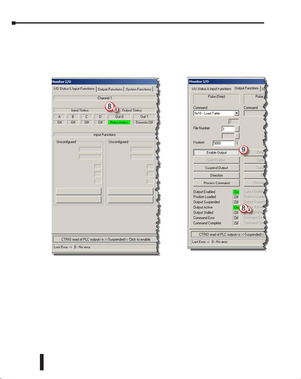
Chapter 2: Getting Started
8: The CTRIO(2):
a. Turns On the Output Active and Output Enabled status bits
b. Generates the appropriate pulse train on Output 0 and Output 1
c. Turns Off the Output Active bit when the move completes
2-28
9: Press the Enable Output button again to
release (reset) it. The CTRIO(2) turns Off the Output Enabled status bit.
10: To initiate another move, repeat steps 6 – 9.
Ladder Example
A detailed ladder example is provided in Chapter 9: Output Functions later in this manual.
Counter I/O User Manual, 3rd Ed., Rev. E
Page 57

Chapter
Chapter
Chapter
InstallatIon and
FIeld WIrIng
3
3
In This Chapter...
Installing the H0-CTRIO(2) Module .......................................................................... 3-2
Setting H0-CTRIO(2) Jumpers ................................................................................... 3-3
H0- CTRIO(2) Quadrature Encoder Wiring Example ................................................ 3-5
H0-CTRIO(2) TTL Quadrature Encoder Field Wiring ............................................... 3-6
H0- CTRIO(2) TTL Input Wiring ................................................................................ 3-7
H0- CTRIO(2) Output Wiring Schematic ................................................................... 3-8
H0-CTRIO(2) Stepper/Servo Drive Wiring Example ................................................. 3-9
Solid State Input Device Wiring to the H0-CTRIO(2) Module ............................... 3-10
Installing the H2-CTRIO(2) Module ........................................................................ 3-11
Setting H2-CTRIO(2) Jumpers ................................................................................. 3-12
Wiring the H2-CTRIO(2) Module ............................................................................ 3-13
H2- CTRIO(2) Quadrature Encoder Wiring Example .............................................. 3-14
H2-CTRIO(2) TTL Quadrature Encoder Field Wiring .............................................. 3-15
H2-CTRIO(2) TTL Input Wiring ............................................................................... 3-16
H2- CTRIO(2) Output Wiring Schematic ................................................................. 3-17
H2-CTRIO(2) Stepper/Servo Drive Wiring Example ............................................... 3-18
Solid State Input Device Wiring to the H2-CTRIO(2) Module ............................... 3-19
Installing the H4-CTRIO ........................................................................................... 3-20
Wiring the H4-CTRIO Module ................................................................................. 3-21
H4-CTRIO Quadrature Encoder Wiring Example .................................................... 3-22
H4-CTRIO TTL Quadrature Encoder Field Wiring ................................................... 3-23
Page 58

Table of Contents
H4-CTRIO TTL Input Wiring .................................................................................... 3-24
H4-CTRIO Output Wiring Schematic ....................................................................... 3-25
H4-CTRIO Stepper/Servo Drive Wiring Example .................................................... 3-26
Solid State Input Device Wiring to the H4-CTRIO Module .................................... 3-27
Installing the T1H-CTRIO ......................................................................................... 3-28
Wiring the T1H-CTRIO Module ............................................................................... 3-29
T1H-CTRIO Quadrature Encoder Wiring Example .................................................. 3-31
T1H-CTRIO TTL Quadrature Encoder Field Wiring ................................................. 3-32
T1H-CTRIO TTL Input Wiring .................................................................................. 3-33
T1H-CTRIO Output Wiring Schematic..................................................................... 3-34
T1H-CTRIO Stepper/Servo Drive Wiring Example .................................................. 3-35
Solid State Input Device Wiring to T1H-CTRIO Module ........................................ 3-36
Page 59

Chapter 3: Installation and Field Wiring
Installing the H0-CTRIO(2) Module
The H0-CTRIO(2) module is compatible with DirectLOGIC DL05 and DL06 PLCs.
Consideration must be given to the firmware versions of the PLCs to assure their compatibility
with the H0-CTRIO(2) (see chart below).
SPECIAL NOTE: For applications requiring multiple CTRIO modules, DirectLOGIC CPUs, and dynamic
access (in ladder logic) to CTRIO data, we recommend using the D2-250-1, D2-260 or DL06 CPU. These
CPUs support Bit-of-Word addressing, 32 bit math instructions and have adequate memory for multiple
CTRIO applications.
The H0-CTRIO(2) module plugs into any option card slot in the DL05 and DL06 base.
For installation instructions, refer to the DL05 or DL06 User Manual (D0-USER-M or
D0-06USER-M).
PLC CPU Firmware DirectSOFT
H0-CTRIO(2)
DL05 v. 4.60 or later v. 4.0, Build 16 or later
DL06 v. 1.40 or later v. 4.0, Build 16 or later
At first power-up the CTRIO(2) module, the OK LED will be blinking. The blinking LED
indicates that the module is in program mode.
3-2
CPU and CTRIO Compatibility Chart
Updated firmware versions can be downloaded from our web site
at www.automationdirect.com.
NOTE: CTRIO Workbench Version 2.2.0 or later is required for the H0-CTRIO2.
Counter I/O User Manual, 3rd Ed., Rev. E
Page 60
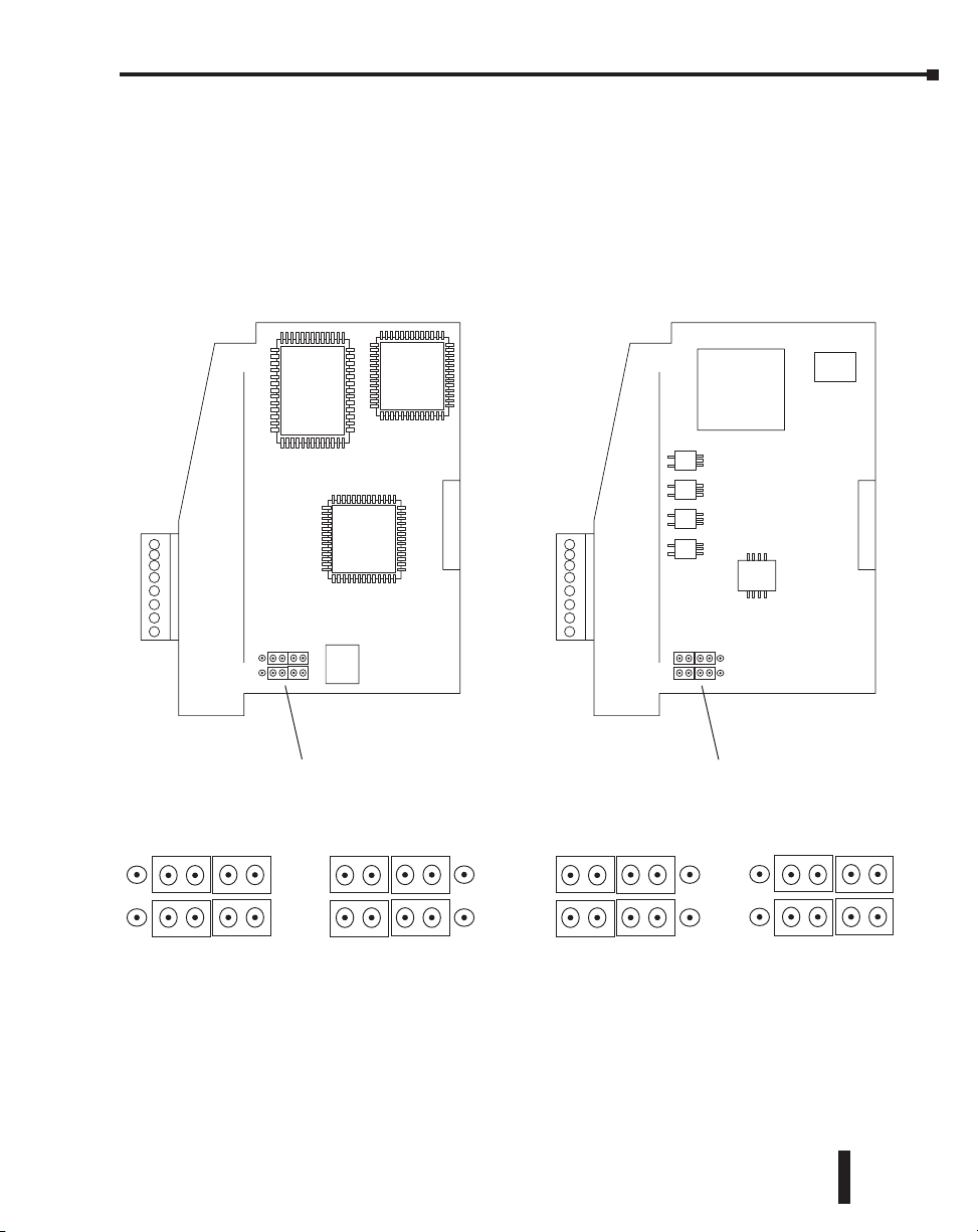
Setting H0-CTRIO(2) Jumpers
The module internal jumpers must be set to the High Common position for high side switching
(sourcing) outputs or to the Low Common position for low side switching (sinking) outputs.
The sink/source jumper selection sets both outputs to the same option. Source operation is the
factory default setting.
H0-CTRIO H0-CTRIO2
Chapter 3: Installation and Field Wiring
Jumper Selections
Sourcing Outputs Sourcing Outputs
High Common position
for switching the high
side of a DC load.
Sinking Outputs
Low Common position
for switching the low
side of a DC load.
High Common position
for switching the high
side of a DC load.
Counter I/O User Manual, 3rd Ed., Rev. E
Jumper Selections
Sinking Outputs
Low Common position
for switching the low
side of a DC load.
3-3
Page 61
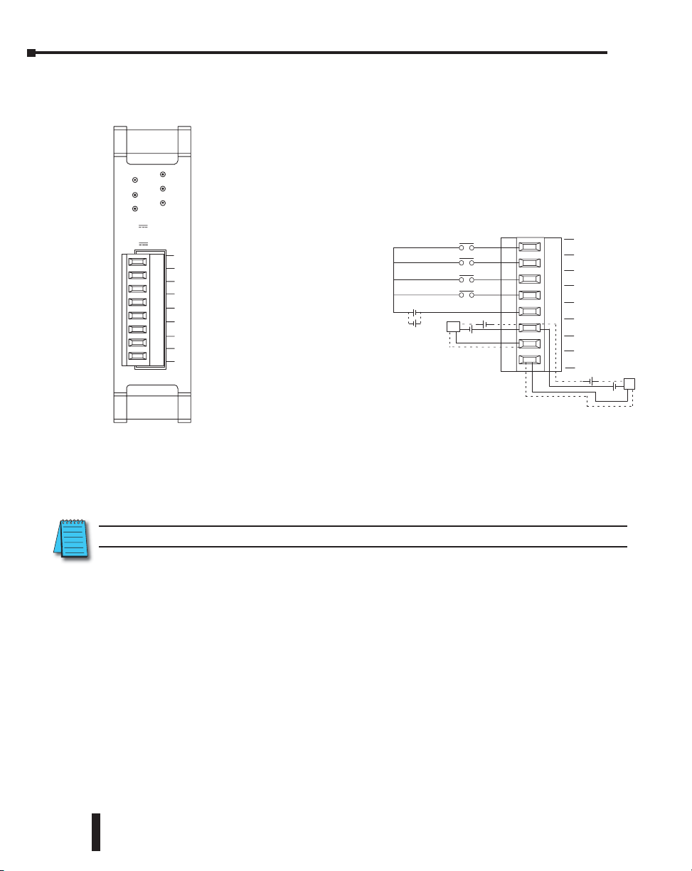
Chapter 3: Installation and Field Wiring
Wiring the H0-CTRIO(2) Module
The H0-CTRIO(2) module has one input channel, consisting of 4 optically
isolated input points (A–D on common M). The inputs can be wired to either
sink or source current.
The module has 2 optically
H0–CTRIO
ERR
isolated output points (Y0–Y1
Y0
on common YC). The outputs
Y1
can be wired to either sink or
source current, but the sink/
IN
source jumper selection sets
A
both outputs to the same option.
B
Sourcing outputs must be wired
C
so positive current flows into the
D
YC terminal and then out of the
M
Yn terminal. Sinking outputs
YC
Y0
must be wired so positive
Y1
current flows into Yn terminal
OUT
and then out of the YC terminal
(see the diagram to the right
and the schematic on page 3-9).
Source operation is the factory
default setting for the outputs.
OK
A
B
CTR/TMR IN
9–30V 5–12mA
DC/Pulse Out
5–36V 1A
The module is configured, using CTRIO Workbench, to accommodate the user’s application.
The function of each input (counting, timing, reset, etc.) and output (pulse output, discrete
output, etc.) is defined in the configuration of the module.
Refer to Chapters 5 and 6 to determine what input and output configurations are possible.
+-
+-
+-
9-30 VDC
L
– +
5-36 VDC
IN
A
B
C
D
– +
M
YC
Y0
Y1
OUT
– +
5-36 VDC
L
– +
3-4
NOTE: Field device wiring must be compatible with the module configuration.
See the notes below for further details about power source considerations, circuit polarities,
and field devices. Also, refer to the specifications in Chapter 1 on pages 1-7 and 1-8 for more
information.
NOTES:
1: Inputs (A, B, C, and D) require user-provided 9–30VDC power sources. Terminal M
is the common for the inputs. Maximum current consumption is 12mA per input
point.
2: Polarity of the input power sources (shown above) can be reversed. Consideration
must be given, however, to the polarity of the field device. Many field devices are
designed for only one polarity and can be damaged if power wiring is reversed.
3: The maximum allowable current per output circuit is 1A.
Counter I/O User Manual, 3rd Ed., Rev. E
Page 62

Chapter 3: Installation and Field Wiring
H0- CTRIO(2) Quadrature Encoder Wiring Example
Sourcing Encoder
A
B
Z
Gnd
Power
9-30VDC
+
OK
A
B
CTR/TMR IN
9–30V 5–12mA
DC/Pulse Out
5–36V 1A
H0–CTRIO
ERR
Y0
Y1
IN
A
B
C
D
M
YC
Y0
Y1
OUT
Counter I/O User Manual, 3rd Ed., Rev. E
3-5
Page 63

Chapter 3: Installation and Field Wiring
H0-CTRIO(2) TTL Quadrature Encoder Field Wiring
ISOLATION
BARRIER
FC-ISO-C
+Ai
-Ai
+Bi
-Bi
+Zi
-Zi
COM
COM
V+
0V
Ao
Ao
Bo
Bo
Zo
Zo
0V
0V
ENCODER
Differential Line
Driver Encoder
Brown: Power source*
Blue: 0 V
Black: OUT A
Purple: OUT A
White: OUT B
Gray: OUT B
Orange: OUT Z
Yellow: OUT Z
Shield: Ground
* Use separate power supply to maintain isolation
PLC High Speed Counter
Interface Module
OK
A
B
CTR/TMR IN
9–30V 5–12mA
DC/Pulse Out
5–36V 1A
H0–CTRIO
+
24VDC
-
ERR
Y0
Y1
IN
A
B
C
D
M
YC
Y0
Y1
OUT
3-6
Counter I/O User Manual, 3rd Ed., Rev. E
Page 64

H0- CTRIO(2) TTL Input Wiring
Chapter 3: Installation and Field Wiring
TTL Device
TTL Device
TTL Device
NPN
General Purpose Transistor
10K
B
0.1W
10%
10K
B
0.1W
10%
10K
B
0.1W
10%
C
HFE > 100
E
C
HFE > 100
E
C
HFE > 100
E
OK
CTR/TMR IN
9–30V 5–12mA
DC/Pulse Out
5–36V 1A
+
-
A
B
H0–CTRIO
9 - 30VDC
ERR
Y0
Y1
IN
A
B
C
D
M
YC
Y0
Y1
OUT
TTL Device
C
10K
B
0.1W
10%
HFE > 100
E
Counter I/O User Manual, 3rd Ed., Rev. E
3-7
Page 65

Chapter 3: Installation and Field Wiring
H0- CTRIO(2) Output Wiring Schematic
See page 3-3 for locating and setting the jumpers
YC
CTRIO
Output
Yn (where n=0 or 1)
+
Load
-
+
Load
-
+5 to 36VDC
+5 to 36VDC
+
+
3-8
Yn (where n=0 or 1)
CTRIO
Output
YC
Counter I/O User Manual, 3rd Ed., Rev. E
Page 66

Chapter 3: Installation and Field Wiring
IN
T
H0-CTRIO(2) Stepper/Servo Drive Wiring Example
NOTE: Sinking output connection shown.
A
B
C
Step Amplifier
Pulse
Direction
OPTO Power
(or CW)
(or CCW)
D
5-36VDC
+-
See page 3-3 for locating and setting the jumpers
M
YC
Y0
Y1
OU
Counter I/O User Manual, 3rd Ed., Rev. E
3-9
Page 67

Chapter 3: Installation and Field Wiring
Solid State Input Device Wiring to the H0-CTRIO(2) Module
NPN Field Device
This drawing illustrates wiring that is
typical for Channel 1 terminals 1A, 1B,
1C, and 1D. The same circuitry is also
present at the corresponding
Channel 2 terminals.
PNP Field Device
Sensing Circuit
Sensing Circuit
24VDC
+-
+
-
24VDC
1A
1M
The same circuitry is present at the
corresponding Channel 2 terminal.
This drawing illustrates wiring that is
typical for Channel 1 terminals 1A, 1B,
1C, and 1D. The same circuitry is also
present at the corresponding
Channel 2 terminals.
1A
3-10
Counter I/O User Manual, 3rd Ed., Rev. E
1M
The same circuitry is present at the
corresponding Channel 2 terminal.
Page 68
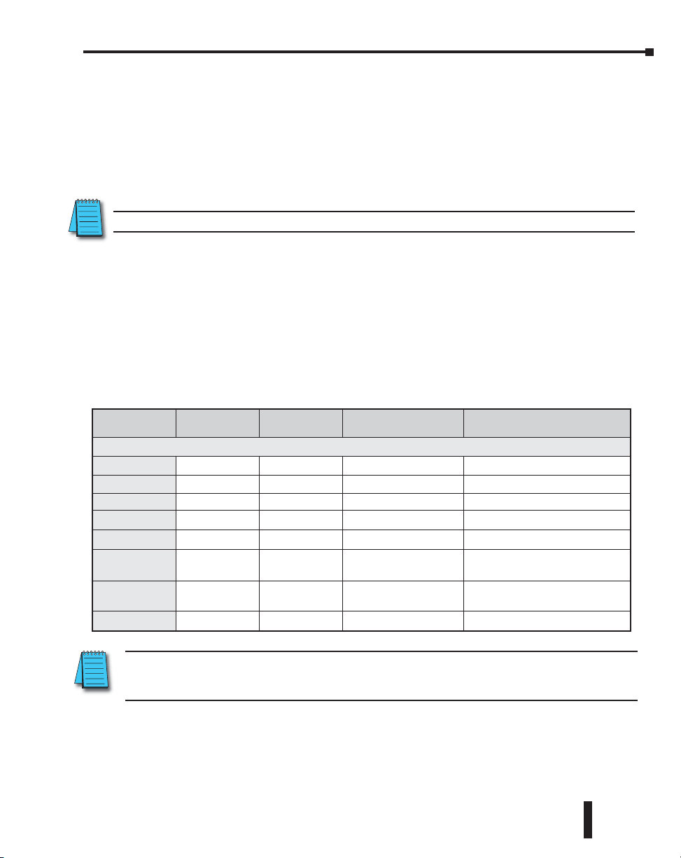
Chapter 3: Installation and Field Wiring
Installing the H2-CTRIO(2) Module
The H2-CTRIO(2) module is compatible with Do-more CPUs and several DL205 CPU/slot
interface devices. Consideration must be given to the firmware version of the CPU to assure
their compatibility with the H2-CTRIO(2) (see chart below).
The H2-CTRIO(2) module plugs into any I/O slot of any Do-more or DirectLOGIC 205 base
except slot 0 when using a DirectLOGIC PLC. Slot 0 is also not allowed if using the H2-CTRIO
and a WinPLC or H2-PBC controller. However, slot 0 is available for the H2-CTRIO(2)
module when using the H2-EBC interface devices (Slot 0 is the I/O slot adjacent to the CPU).
NOTE: The H2-CTRIO(2) cannot be used in DL205 local expansion bases or in Serial Remote I/O bases.
For installation instructions, refer to the:
• DL205 User Manual (D2-USER-M) if using a DirectLOGIC PLC
• DL205 Installation and I/O Manual (D2-INST-M) if
using a WinPLC, EBC or PBC module.
• Do-more H2 series PLC Harware User Manual (H2-DM-M) if using a Do-more PLC
At first power-up of the CTRIO(2) module, the OK LED will be blinking. The blinking LED
indicates that the module is in program mode.
CPU and CTRIO Compatibility Chart
CPU-slot
Device
H2-CTRIO(2)
D2-240 v. 3.22 or later Any v. 3.0C, Build 71 or later any I/O slot except 0
D2-250 v. 1.56 or later Any v. 3.0C, Build 71 or later any I/O slot except 0
D2-250-1 v. 3.5 or later Any v. 3.0C, Build 71 or later any I/O slot except 0
D2-260 v. 1.2 or later Any v. 4.0 or later any I/O slot except 0
H2-WinPLC Any xK or later N/A any I/O slot except 0
H2-EBC v. 2.1.357 or later Any N/A
H2-PBC Any Any N/A
Do-more Any Any N/A No Restrictions
NOTE: CTRIO Workbench version 2.2.0 or later is required for H2-CTRIO2. However, with a Do-more
CPU, CTRIO Workbench is not used at all. Instead, the Do-more Designer Module Configuration is used to
configure the H2-CTRIO2.
Firmware Hardware DirectSOFT Slot Restrictions
prior to Rev 9A any I/O slot except 0;
Rev 9A or later any I/O slot
prior to Rev 4A any I/O slot except 0;
Rev 4A or later any I/O slot
Updated firmware versions can be downloaded from our web site at
www.automationdirect.com.
Counter I/O User Manual, 3rd Ed., Rev. E
3-11
Page 69
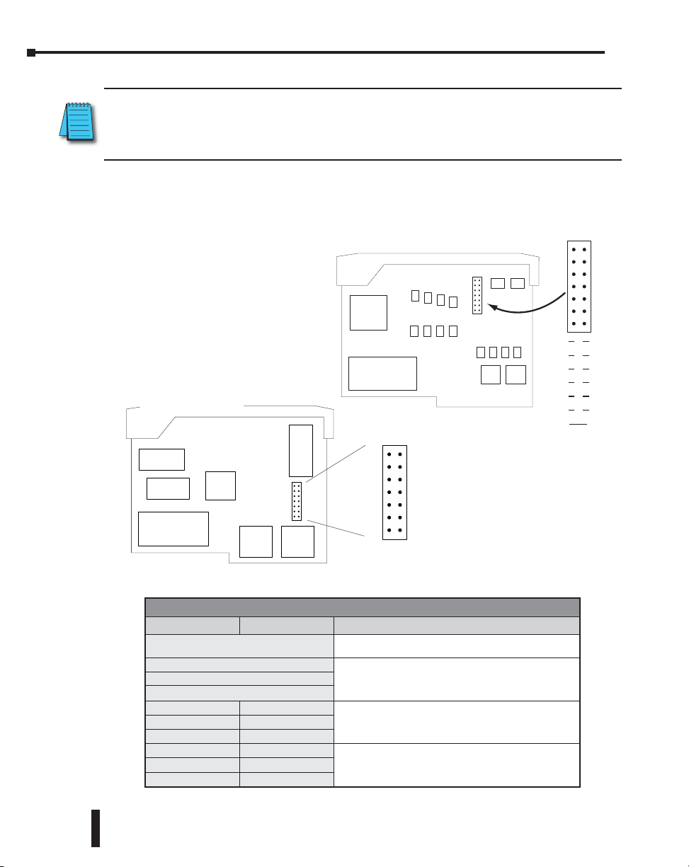
Chapter 3: Installation and Field Wiring
Setting H2-CTRIO(2) Jumpers
SPECIAL NOTE: For applications requiring multiple CTRIO modules, DirectLOGIC CPUs, and dynamic
access (in ladder logic) to CTRIO data, we recommend using the D2-250-1 or D2-260 CPU. These
CPUs support Bit-of-Word addressing, 32 bit math instructions and have adequate memory for multiple
CTRIO applications.
Jumpers are provided to connect input commons or outputs/output commons. Use of these
jumpers is not necessary to set up the CTRIO(2) module. The jumpers are provided solely for
convenience in wiring.
H2-CTRIO
H2-CTRIO2
C3
C3
C3
Y2
Y3
Y1
M2
H
C0
H
C2
H
C1
L
Y0
L
Y0
L
Y0
M1
3-12
H2-CTRIO(2) Jumper Functions
H2-CTRIO H2-CTRIO2 Function
1M-2M
Y0-Y1
Y0-Y2
Y0-Y3
C0-C1
C0-C2
C0-C3
C3-C0
C3-C1
C3-C2
Install jumper to internally connect the input commons 1M and 2M
in order to reduce wiring if appropriate.
Install jumper(s) to internally connect Y0 to other Y terminals in
order to reduce wiring if appropriate. Connect wire at Y0.
Install jumper(s) to internally connect C0 to other C terminals in
order to reduce wiring if appropriate. Connect wire at C0.
Install jumper(s) to internally connect C3 to other C terminals in
order to reduce wiring if appropriate. Connect wire at C3.
Counter I/O User Manual, 3rd Ed., Rev. E
1M 2M
Y0
Y0
Y0
C0
C0
C0
Y1
Y2
Y3
C1
C2
C3
Page 70

Wiring the H2-CTRIO(2) Module
CTR+24VDC
I
N
K
O
R
E
C
1
2
C
TR
H2-- CTRI
IN-930VDC
T
-5 36VDC
U
O
1. 0A max
er point
p
1A
2A
1B
2B
1C
2C
1D
2D
1M
2M
NC
C2
C0
Y2
Y0
C3
C1
Y3
Y1
5-12m
OUT
P
0
1
2
3
O
A
Refer to Chapters 5 and 6 to determine what input and output configurations are possible.
The H2-CTRIO(2) module has two independent input channels,
each consisting of 4 optically isolated input points (1A–1D on
UST
common 1M and 2A–2D on common 2M). The inputs can be
wired to either sink or source current. The module has 4 optically
isolated output points (pts. Y0–Y3 with isolated commons C0–C3,
respectively). The outputs must be wired so positive current flows
into C(n) terminal and then out of the Y(n) terminal (see diagram
2A
2B
2C
2D
2
+-
-
+
L
– +
– +
L
– +
– +
Chapter 3: Installation and Field Wiring
at left and the schematic on
1A
1
B
C
1
1D
1
M
M
2C
2Y
3C
3Y
+-
N
C
0
C
Y
0
– +
C
1
Y1
– +
page 3-17). Remember that
the internal jumpers can be
used to connect the input
commons or outputs/output
commons together.
The module is configured,
using CTRIO Workbench,
+-
to accommodate the user’s
application. The function of
each input (counting, timing,
reset, etc.) and output (pulse
L
output, discrete output, etc.)
– +
is defined in the configuration
of the module.
L
– +
NOTE: Field device wiring must be compatible with the module configuration.
See the notes below for further details about power source considerations, circuit polarities,
and field devices.
NOTES:
1: Inputs (1A, 1B, 1C, 1D and 2A, 2B, 2C, 2D) require user-provided 9-30VDC power
sources. Terminals 1M and 2M are the commons for Channel 1 and Channel 2
inputs. Maximum current consumption is 12mA per input point.
2: Polarity of the input power sources (shown above) can be reversed. Consideration
must be given, however, to the polarity of the field device. Many field devices are
designed for only one polarity and can be damaged if power wiring is reversed.
3: Outputs have one polarity only (as shown above) and are powered by user-provided
5-36VDC power sources. The maximum allowable current per output circuit is 1A
for the H2-CTRIO and 1A at 23°C or 0.5A at 60°C for the H2-CTRIO2.
Counter I/O User Manual, 3rd Ed., Rev. E
3-13
Page 71
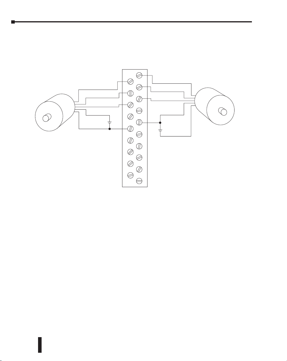
Chapter 3: Installation and Field Wiring
H2- CTRIO(2) Quadrature Encoder Wiring Example
1A
Sourcing Encoder
A
B
Z
Power
Gnd
+
-
2A
2B
2C
2D
M
2
9-30VDC
2C
2Y
3C
3Y
1
B
C
1
1D
1
M
9-30VDC
N
C
0
C
0
Y
C1
Y1
A
B
Z
Power
+
-
Gnd
Open Collector Encoder
3-14
Counter I/O User Manual, 3rd Ed., Rev. E
Page 72
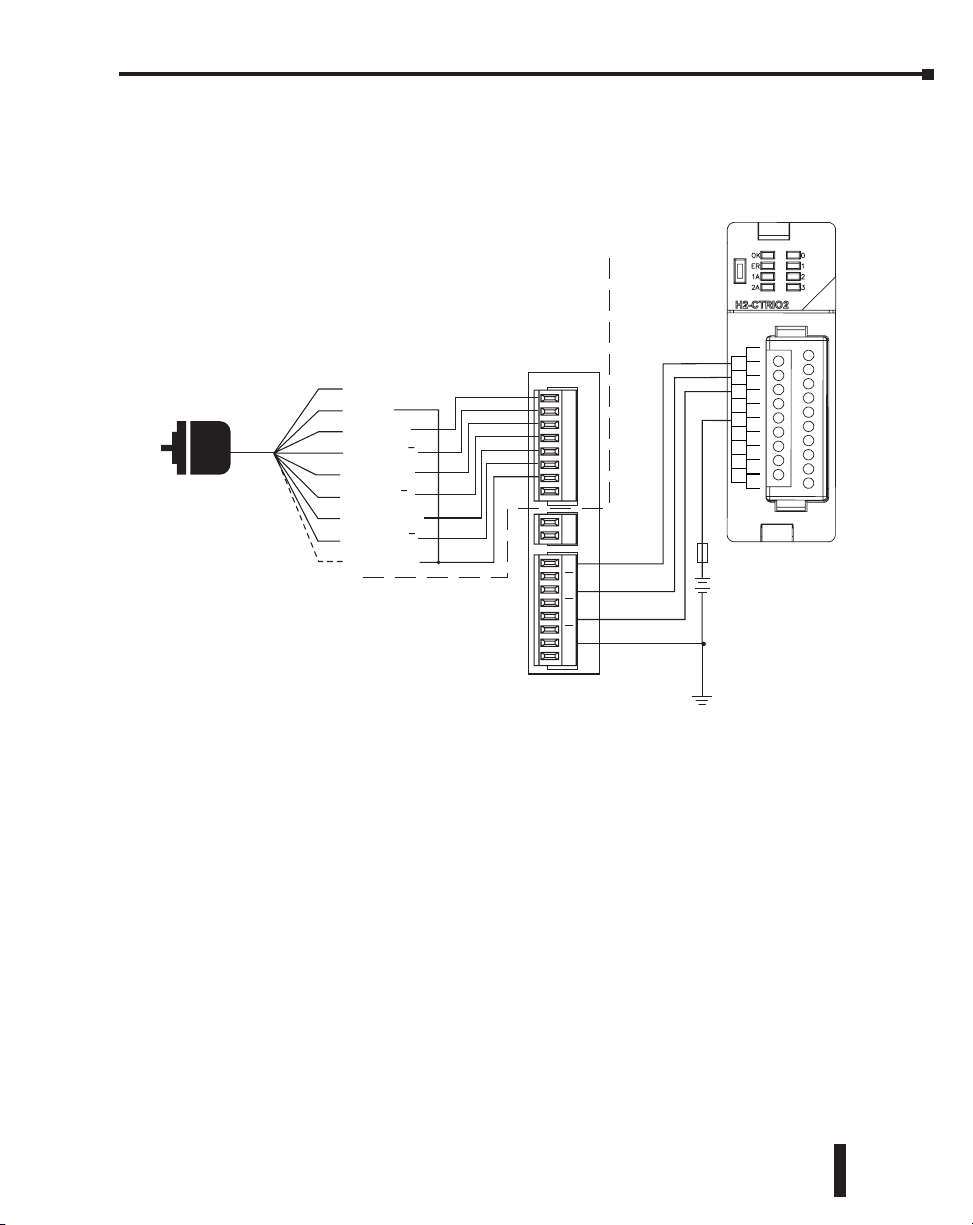
Chapter 3: Installation and Field Wiring
H2-CTRIO(2) TTL Quadrature Encoder Field Wiring
CTR
IN 9-30 VDC 5-12 mA
OUT 5-36 VDC
1.0 max
per point
2A
2B
2C
2D
2M
C2
Y2
C3
Y3
PLC High Speed Counter
Interface Module
+
24VDC
-
IN
1A
1B
1C
1D
1M
NC
C0
Y0
C1
Y1
ENCODER
Differential Line
Driver Encoder
Brown: Power source*
Blue: 0 V
Black: OUT A
Purple: OUT A
White: OUT B
Gray: OUT B
Orange: OUT Z
Yellow: OUT Z
Shield: Ground
* Use separate power supply to maintain isolation
FC-ISO-C
+Ai
-Ai
+Bi
-Bi
+Zi
-Zi
COM
COM
V+
0V
Ao
Ao
Bo
Bo
Zo
Zo
0V
0V
ISOLATION
BARRIER
+24 VDC
OUTPUTS
Counter I/O User Manual, 3rd Ed., Rev. E
3-15
Page 73

Chapter 3: Installation and Field Wiring
NPN
H2-CTRIO(2) TTL Input Wiring
+
-
General Purpose Transistor
C
B
HFE > 100
E
C
B
HFE > 100
E
C
B
HFE > 100
E
C
B
HFE > 100
E
0.1W
0.1W
0.1W
10K
0.1W
10%
10K
10%
10K
10%
10K
10%
TTL Device
TTL Device
TTL Device
TTL Device
1A
2A
1
B
2B
C
1
2C
1D
2D
1
M
M
2
N
C
2C
0
C
2Y
0
Y
3C
C1
3Y
Y1
9 - 30VDC
3-16
Counter I/O User Manual, 3rd Ed., Rev. E
Page 74

Chapter 3: Installation and Field Wiring
H2- CTRIO(2) Output Wiring Schematic
The CTRIO outputs are individually isolated DC switches that can be used to break the high
or the low side of a DC load.
Cn (where n=0, 1, 2, 3)
CTRIO
Output
Yn
+
Load
-
+
Load
-
+5 to 36VDC
+5 to 36VDC
+
+
Cn (where n=0, 1, 2, 3)
CTRIO
Output
Yn
NOTE: The outputs must be wired so positive current flows into C(n) terminal and then out of the Y(n)
terminal.
Counter I/O User Manual, 3rd Ed., Rev. E
3-17
Page 75

Chapter 3: Installation and Field Wiring
1A
H2-CTRIO(2) Stepper/Servo Drive Wiring Example
2A
1
B
Step Amplifier
OPTO Power
(or CW)
Pulse
(or CCW)
Direction
CTRIO - Sinking
2B
2C
2D
2
5-36VDC
+-
C
1
1D
1
M
M
N
C
2C
0
C
5-36VDC
2Y
3C
3Y
+-
0
Y
C1
Y1
Step Amplifier
DIR +
DIR -
STEP +
STEP -
CTRIO - Sourcing
3-18
This example assumes that the Step Amplifier interface to be optocoupler LEDs
(common anodes at the “OPTO Power” terminal) with internal current limiting resistors.
This is a standard method; consult the step amplifier documentation to ensure that this
method is applicable.
Counter I/O User Manual, 3rd Ed., Rev. E
Page 76
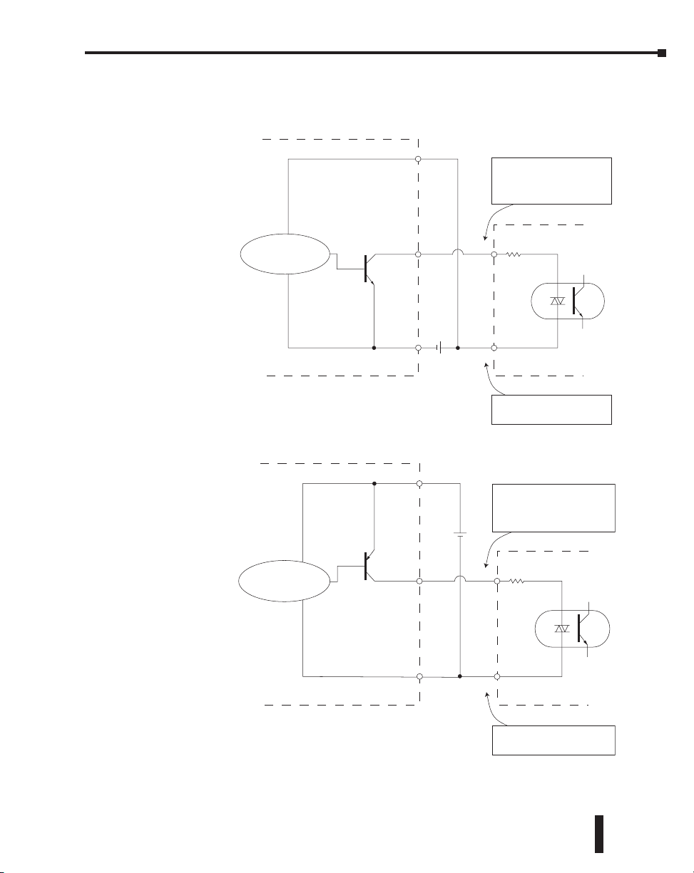
Chapter 3: Installation and Field Wiring
Solid State Input Device Wiring to the H2-CTRIO(2) Module
NPN Field Device
This drawing illustrates wiring that is
typical for Channel 1 terminals 1A, 1B,
1C, and 1D. The same circuitry is also
present at the corresponding
Channel 2 terminals.
PNP Field Device
Sensing Circuit
Sensing Circuit
24VDC
+-
+
-
24VDC
1A
1M
The same circuitry is present at the
corresponding Channel 2 terminal.
This drawing illustrates wiring that is
typical for Channel 1 terminals 1A, 1B,
1C, and 1D. The same circuitry is also
present at the corresponding
Channel 2 terminals.
1A
1M
The same circuitry is present at the
corresponding Channel 2 terminal.
Counter I/O User Manual, 3rd Ed., Rev. E
3-19
Page 77

Chapter 3: Installation and Field Wiring
Installing the H4-CTRIO
The H4-CTRIO module is compatible with two DL405 CPU/slot interface devices.
Consideration must be given to the firmware versions of the CPU-slot interfaces to assure their
compatibility with the H4-CTRIO, (see chart below).
The H4-CTRIO module plugs into any I/O slot of any DirectLOGIC 405 base. H4-EBCs
support the use of the H4-CTRIO in DL405 local expansion bases. The H4-CTRIO cannot
be used in Serial Remote I/O bases.
For installation instructions, refer to the:
• DL405 User Manual (D4-USER-M) if using a DirectLOGIC PLC
• DL405 Installation and I/O Manual (D4-INST-M) if using an H4-EBC interface
At first power-up of the CTRIO module, the OK LED will be blinking. The blinking LED
indicates that the module is in program mode.
CPU and CTRIO Compatibility Chart
CPU-slot Device Firmware* Hardware DirectSOFT
April 2000 or earlier:
H8 (CISC) v. 2.00
D4-450
SH (RISC) v. 1.500
May 2000 or later:
H8 (CISC) v. 2.00
SH (RISC) v. 2.500
Any v. 4.0, Build 16 or later
3-20
H4-EBC 2.1.328 or later v. 4F or later N/A
*Updated firmware versions can be downloaded from our web site at www.automationdirect.com
Counter I/O User Manual, 3rd Ed., Rev. E
Page 78

Wiring the H4-CTRIO Module
Chapter 3: Installation and Field Wiring
The H4-CTRIO module has two independent input
channels, each consisting of 4 optically isolated input points
(1A–1D on common 1M and 2A–2D on common 2M).
The inputs can be wired to either sink or source current.
The module has 4 optically isolated output points (Y0–Y3 on
isolated commons C0-C3, respectively). The outputs must be
wired so that positive current flows into Cn terminal and then out
of the Yn terminal (See the diagram below and the schematic on
page 3-25).
COUNTER I/O
OK ER
2A
F1
2B
F2
2C
Y2
2D
Y3
H4–CTRIO
:
INPUT
9–30VDC
5–12mA
OUTPUT:
9–36VDC
1.0A Max
per point
The module is configured, using CTRIO Workbench, to
accommodate the user’s application. The function of each input
(counting, timing, reset,
etc.) and output (pulse
output, discrete output,
etc.) is defined in the
configuration of the
module.
Refer to Chapters 5 and
6 to determine possible
input and output
configurations.
NOTE: Field device wiring
must be compatible with the
module configuration.
See the notes below for
further details about power
source considerations,
circuit polarities, and field
– +
L
L
– +
– +
– +
– +
– +
2A
2B
2C
2D
2M
NC
C2
Y2
C3
Y3
1A
1B
1C
1D
– +
– +
– +
– +
– +
– +
L
L
1M
NC
C0
Y0
C1
Y1
+
+
L
L
+
L
L
+
H4–CTRIO
+
+
+
devices. Also, refer to the
specifications in Chapter 1
on pages 1-7 and 1-8 for more information.
NOTES:
1: Inputs (1A, 1B, 1C, 1D and 2A, 2B, 2C, 2D) require user-provided 9–30VDC
power sources. Terminals 1M and 2M are the commons for Channel 1 and Channel
2 inputs. Maximum current consumption is 12mA per input point.
2: Polarity of the input power sources (shown above) can be reversed. Consideration
must be given, however, to the polarity of the field device. Many field devices are
designed for only one polarity and can be damaged if power wiring is reversed.
3: Outputs have one polarity only (as shown above) and are powered by user-provided
5–36 VDC power sources. The maximum allowable current per output circuit is 1A.
TB
1A
F1
1B
F2
1C
Y0
1D
Y1
1A
2A
1B
2B
1C
2C
1D
2D
1M
+
2M
NC
NC
+
C0
+
C2
Y0
Y2
+
C1
+
C3
Y1
Y3
Counter I/O User Manual, 3rd Ed., Rev. E
3-21
Page 79

Chapter 3: Installation and Field Wiring
H4-CTRIO Quadrature Encoder Wiring Example
Sourcing Encoder
A
B
Z
Gnd
Power
+
2A
2B
2C
2D
2M
NC
9-30VDC
C2
Y2
C3
Y3
1A
1B
1C
1D
1M
9-30VDC
NC
+
-
C0
Y0
C1
Y1
A
B
Z
Power
Gnd
Open Collector Encoder
3-22
Counter I/O User Manual, 3rd Ed., Rev. E
Page 80
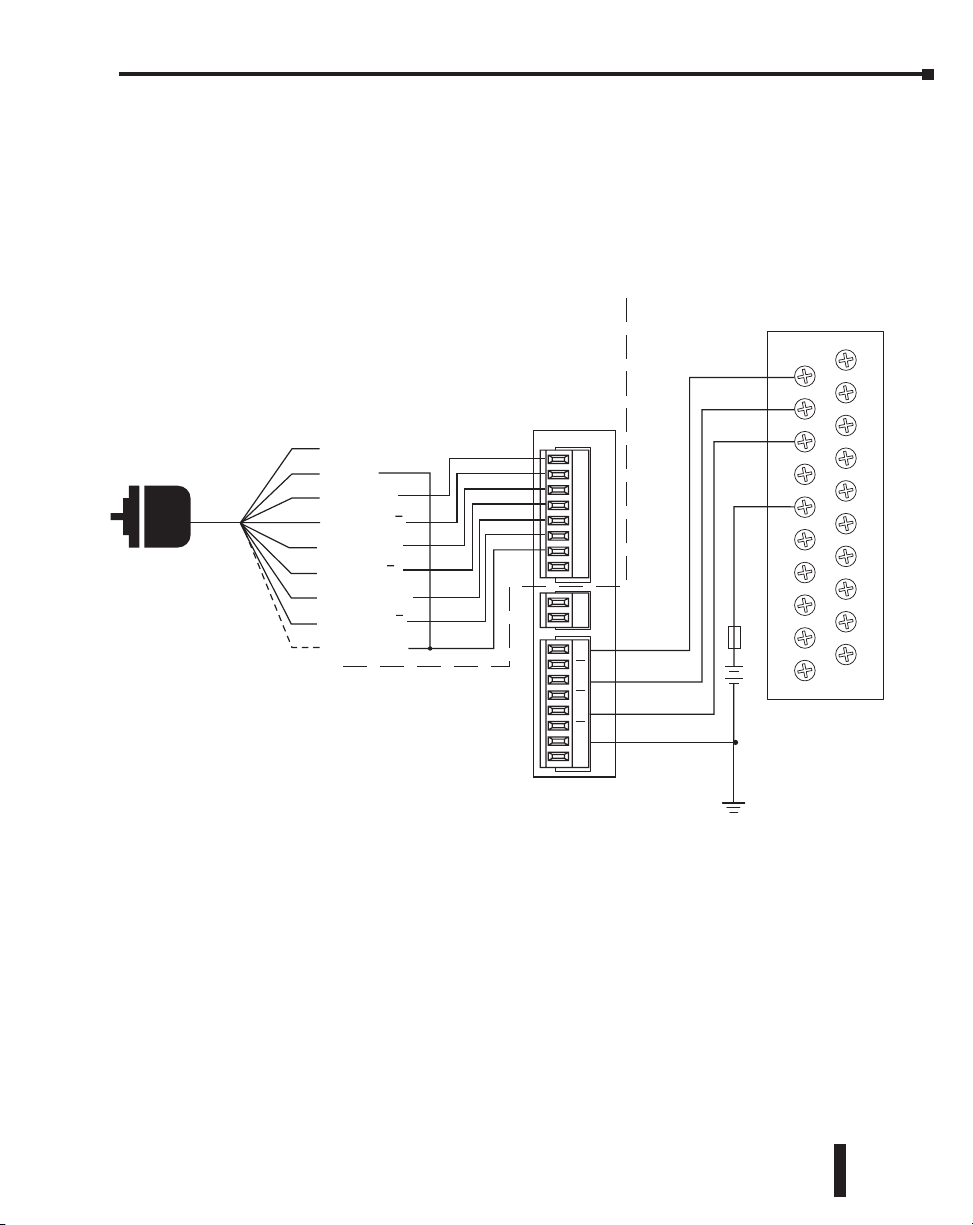
Chapter 3: Installation and Field Wiring
H4-CTRIO TTL Quadrature Encoder Field Wiring
ISOLATION
BARRIER
PLC High Speed Counter
Interface Module
ENCODER
Differential Line
Driver Encoder
Brown: Power source*
Blue: 0 V
Black: OUT A
Purple: OUT A
White: OUT B
Gray: OUT B
Orange: OUT Z
Yellow: OUT Z
Shield: Ground
* Use separate power supply to maintain isolation
FC-ISO-C
+Ai
-Ai
+Bi
-Bi
+Zi
-Zi
COM
COM
V+
0V
Ao
Ao
Bo
Bo
Zo
Zo
0V
0V
2A
2B
2C
2D
2M
NC
C2
Y2
C3
+
Y3
24VDC
-
1A
1B
1C
1D
1M
NC
C0
Y0
C1
Y1
Counter I/O User Manual, 3rd Ed., Rev. E
3-23
Page 81

Chapter 3: Installation and Field Wiring
NPN
H4-CTRIO TTL Input Wiring
2A
2B
2C
2D
2M
NC
C2
Y2
C3
Y3
1A
1B
1C
1D
1M
NC
C0
Y0
C1
Y1
General Purpose Transistor
C
B
HFE > 100
E
C
B
HFE > 100
E
10K
0.1W
10%
10K
0.1W
10%
TTL Device
TTL Device
+
-
9 - 30VDC
HFE > 100
HFE > 100
C
10K
B
0.1W
10%
E
C
10K
B
0.1W
10%
E
TTL Device
TTL Device
3-24
Counter I/O User Manual, 3rd Ed., Rev. E
Page 82

Chapter 3: Installation and Field Wiring
H4-CTRIO Output Wiring Schematic
The CTRIO outputs are individually isolated DC switches that can be used to break the high
or the low side of a DC load.
Cn (where n=0, 1, 2, 3)
CTRIO
Output
Yn
+
Load
-
+
Load
-
+5 to 36VDC
+5 to 36VDC
+
+
Cn (where n=0, 1, 2, 3)
CTRIO
Output
Yn
NOTE: The outputs must be wired so that positive current flows into Cn terminal and then out of the Yn
terminal.
Counter I/O User Manual, 3rd Ed., Rev. E
3-25
Page 83

Chapter 3: Installation and Field Wiring
H4-CTRIO Stepper/Servo Drive Wiring Example
1A
1B
1C
1D
1M
NC
C0
Y0
C1
Y1
5-36VDC
+-
Step Amplifier
DIR +
DIR -
STEP +
STEP -
CTRIO - Sourcing
Step Amplifier
OPTO Power
Pulse
Direction
CTRIO - Sinking
(or CW)
(or CCW)
5-36VDC
+-
2A
2B
2C
2D
2M
NC
C2
Y2
C3
Y3
This example assumes that the Step Amplifier interface to be optocoupler LEDs (common anodes
at the “OPTO Power” terminal) with internal current limiting resistors. This is a standard
method; consult the step amplifier documentation to ensure that this method is applicable.
3-26
Counter I/O User Manual, 3rd Ed., Rev. E
Page 84

Chapter 3: Installation and Field Wiring
Solid State Input Device Wiring to the H4-CTRIO Module
NPN Field Device
This drawing illustrates wiring that is
typical for Channel 1 terminals 1A, 1B,
1C, and 1D. The same circuitry is also
present at the corresponding
Channel 2 terminals.
PNP Field Device
Sensing Circuit
Sensing Circuit
24VDC
+-
+
-
24VDC
1A
1M
The same circuitry is present at the
corresponding Channel 2 terminal.
This drawing illustrates wiring that is
typical for Channel 1 terminals 1A, 1B,
1C, and 1D. The same circuitry is also
present at the corresponding
Channel 2 terminals.
1A
1M
The same circuitry is present at the
corresponding Channel 2 terminal.
Counter I/O User Manual, 3rd Ed., Rev. E
3-27
Page 85

Chapter 3: Installation and Field Wiring
Installing the T1H-CTRIO
The T1H-CTRIO module is compatible with several Terminator I/O Network interface
devices. Consideration must be given to the firmware versions of the Network interfaces to
assure their compatibility with the T1H-CTRIO, (see chart below).
NOTE: The T1H-CTRIO is only supported by the T1H-EBC, T1H-EBC100 and T1H-PBC (Obsoleted 08/20).
The T1H-CTRIO module plugs into any valid I/O slot in a Terminator I/O system. The
T1H-CTRIO cannot be used with the Network interfaces: T1K-RSSS, T1K-MODBUS and
T1K-DEVNETS.
For installation instructions, refer to the Terminator I/O Installation and I/O Manual
(T1K-INST-M)
CPU and CTRIO Compatibility Chart
CPU-slot Device Firmware* Hardware
T1H-EBC v. 1.0.444 or later v. 2I or later
T1H-EBC100 Any Any
T1H-PBC** v. 1.1.10 or later v. 2D or later
*Updated firmware versions can be downloaded from our web site at www.automationdirect.com
** T1H-PBC obsoleted 08/20.
3-28
At first power-up of the CTRIO module, the OK LED will be blinking. The blinking LED
indicates that the module is in program mode.
Counter I/O User Manual, 3rd Ed., Rev. E
Page 86
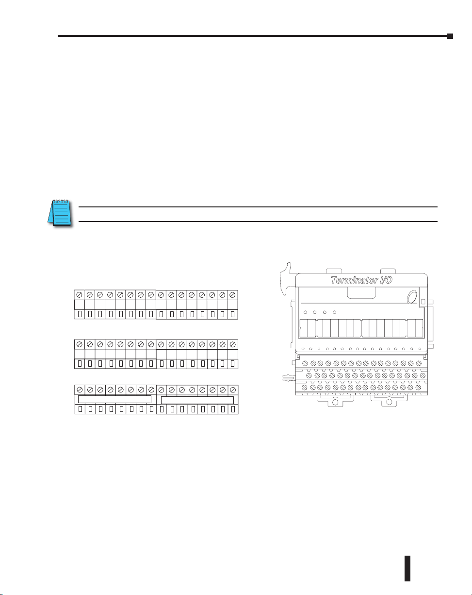
Wiring the T1H-CTRIO Module
The T1H-CTRIO module has two independent input channels, each consisting of 4
optically isolated input points (1A–1D on common 1M and 2A–2D on common 2M). The
inputs can be wired to either sink or source current.
The module has 4 optically isolated output points (Y0–Y3 on isolated commons C0–C3,
respectively). The outputs must be wired so that positive current flows into Cn terminal and
then out of the Yn terminal, (see the diagram on the following page and the schematic on
page 3-34).
The module is configured, using CTRIO Workbench, to accommodate the user’s application.
The function of each input (counting, timing, reset, etc.) and output (pulse output, discrete
output, etc.) is defined in the configuration of the module.
Refer to Chapters 5 and 6 to determine what input and output configurations are possible.
NOTE: Field device wiring must be compatible with the module configuration.
See the notes below for further details about power source considerations, circuit polarities,
and field devices. Also, refer to the specifications in Chapter 1 on pages 1-7 and 1-8 for more
information.
Apply the labels that come with the I/O module to the I/O base
terminals to properly identify the base terminal points.
Input / Output Channels
1A
1B 1C 1D Y0
Y0 Y1 Y1 2A 2B 2C 2D Y2 Y2 Y3 Y3
Chapter 3: Installation and Field Wiring
T1H–CTRIO
OK ERR CH1
CH2
Channel Commons
C1 C1 2M 2M 2M 2M C2 C2 C3 C3
1M 1M 1M 1M C0
–––––––USER BUS 1–––––––
C0
User Bus Terminals (no internal connection to CTRIO)
–––––––USER BUS 2–––––––
1A 1B 1C 1D 2A 2B 2C 2DY0 Y1 Y2 Y3
NOTES:
1: Inputs (1A, 1B, 1C, 1D and 2A, 2B, 2C, 2D) require user-provided 9–30VDC
power sources. Terminals 1M and 2M are the commons for Channel 1 and Channel
2 inputs. Maximum current consumption is 12mA per input point.
2: Polarity of the input power sources can be reversed. Consideration must be given,
however, to the polarity of the field device. Many field devices are designed for only
one polarity and can be damaged if power wiring is reversed.
3: Outputs have one polarity only and are powered by user-provided 5–36VDC power
sources. The maximum allowable current per output circuit is 1A.
4: User Bus 1 and User Bus 2 are each an independent 8 wiring terminal bus. They can
be used for additional power rail connections.
Counter I/O User Manual, 3rd Ed., Rev. E
2
3-29
Page 87

Chapter 3: Installation and Field Wiring
Input / Output Channels
Input / Output Channels
T1H-CTRIO Input Field Wiring
NPN Device
Output
_
+
NPN Device
Output
_
+
1A 1B 1C 1D Y0
1M 1M 1M 1M C0
User Bus Terminals (no internal connection to CTRIO)
–––––––USER BUS 1–––––––
T1H-CTRIO Output Field Wiring
1A
1B 1C 1D Y0
1M 1M 1M 1M C0
User Bus Terminals (no internal connection to CTRIO)
CTRIO
Source To Load
From "Y0"
+
L
-
Y0 Y1 Y1 2A 2B 2C 2D Y2 Y2 Y3 Y3
Channel Commons
C1 C1 2M 2M 2M 2M C2 C2 C3
C0
–––––––USER BUS 2–––––––
+
9-30VDC
-
Y0 Y1 Y1 2A 2B 2C 2D Y2 Y2 Y3 Y3
Channel Commons
C1 C1 2M 2M 2M 2M C2 C2 C3 C3
C0
USER BUS 1 = 1M = +24VDC
USER BUS 2 = 2M = 0VDC
C3
PNP Device
Output
_
+
CTRIO
Sink From Load
into "C1"
PNP Device
-
L
+
Output
_
+
3-30
–––––––USER BUS 1–––––––
+
5-36VDC
-
Counter I/O User Manual, 3rd Ed., Rev. E
–––––––USER BUS 2–––––––
USER BUS 1 = C0 = +24VDC
USER BUS 2 = Y1 = 0VDC
Page 88

Chapter 3: Installation and Field Wiring
USER BUS 1 = 1M = +24VDC
T1H-CTRIO Quadrature Encoder Wiring Example
Input / Output Channels
NPN Open Collector Output
Encoder
Gnd -
A
B
Z
Power +
1B 1C 1D Y0
1A
1M 1M 1M 1M C0
–––––––USER BUS 1–––––––
Y0 Y1 Y1 2A 2B 2C 2D Y2 Y2 Y3 Y3
Channel Commons
C1 C1 2M 2M 2M 2M C2 C2 C3 C3
C0
User Bus Terminals (no internal connection to CTRIO)
9-30VDC
+
-
–––––––USER BUS 2–––––––
USER BUS 2 = 0VDC
Counter I/O User Manual, 3rd Ed., Rev. E
3-31
Page 89

Chapter 3: Installation and Field Wiring
T1H-CTRIO TTL Quadrature Encoder Field Wiring
ENCODER
Differential Line
Driver Encoder
Brown: Power source*
Blue: 0 V
Black: OUT A
Purple: OUT A
White: OUT B
Gray: OUT B
Orange: OUT Z
Yellow: OUT Z
Shield: Ground
* Use separate power supply to maintain isolation
FC-ISO-C
+Ai
-Ai
+Bi
-Bi
+Zi
-Zi
COM
COM
V+
0V
Ao
Ao
Bo
Bo
Zo
Zo
0V
0V
ISOLATION
BARRIER
TTL Input Wiring Example
Input / Output Channels
1B 1C 1D Y0
1A
1M 1M 1M 1M C0 C0 C1 C1 2M 2M 2M 2M C2 C2 C3 C3
9–30
VDC
Y0 Y1 Y1 2A 2B 2C 2D Y2 Y2 Y3 Y3
Channel Commons
PLC High Speed Counter Interface Module
3-32
Counter I/O User Manual, 3rd Ed., Rev. E
Page 90

T1H-CTRIO TTL Input Wiring
Input / Output Channels
Chapter 3: Installation and Field Wiring
TTL Device
TTL Device
9 - 30VDC
TTL Device
TTL Device
NPN
General Purpose Transistor
10K
B
0.1W
10%
10K
B
0.1W
10%
10K
B
0.1W
10%
10K
B
0.1W
10%
C
HFE > 100
E
C
HFE > 100
E
C
HFE > 100
E
C
HFE > 100
E
1B 1C 1D Y0
1A
1M 1M 1M 1M C0
User Bus Terminals (no internal connection to CTRIO)
–––––––USER BUS 1–––––––
+
-
9 - 30VDC
Y0 Y1 Y1 2A 2B 2C 2D Y2 Y2 Y3 Y3
Channel Commons
C1 C1 2M 2M 2M 2M C2 C2 C3 C3
C0
–––––––USER BUS 2–––––––
Counter I/O User Manual, 3rd Ed., Rev. E
3-33
Page 91

Chapter 3: Installation and Field Wiring
T1H-CTRIO Output Wiring Schematic
The CTRIO outputs are individually isolated DC switches that can be used to break the high
or the low side of a DC load.
Cn (where n=0, 1, 2, 3)
CTRIO
Output
Yn
+
Load
-
+
Load
-
+5 to 36VDC
+5 to 36VDC
+
+
3-34
Cn (where n=0, 1, 2, 3)
CTRIO
Output
Yn
NOTE: The outputs must be wired so that positive current flows into Cn terminal and then out of the Yn
terminal.
Counter I/O User Manual, 3rd Ed., Rev. E
Page 92
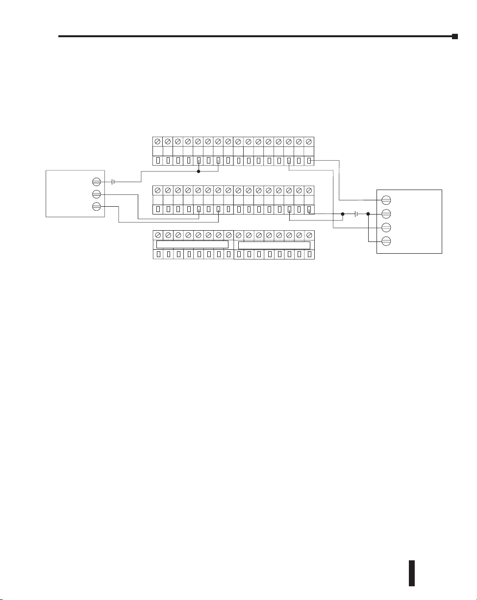
Chapter 3: Installation and Field Wiring
T1H-CTRIO Stepper/Servo Drive Wiring Example
Input / Output Channels
Pulse
Direction
Y0 Y1 Y1 2A 2B 2C 2D Y2 Y2 Y3 Y3
Channel Commons
C1 C1 2M 2M 2M 2M C2 C2 C3 C3
C0
User Bus Terminals (no internal connection to CTRIO)
–––––––USER BUS 2–––––––
5-36VDC
+-
Step Amplifier
DIR +
DIR -
STEP +
STEP -
Step Amplifier
OPTO Power
(or CW)
(or CCW)
5-36VDC
+-
1A
1B 1C 1D Y0
1M 1M 1M 1M C0
–––––––USER BUS 1–––––––
This example assumes that the Step Amplifier interface to be optocoupler LEDs
(common anodes at the “OPTO Power” terminal) with internal current limiting resistors.
This is a standard method; consult the step amplifier documentation to ensure that this
method is applicable.
Counter I/O User Manual, 3rd Ed., Rev. E
3-35
Page 93

Chapter 3: Installation and Field Wiring
Solid State Input Device Wiring to T1H-CTRIO Module
NPN Field Device
This drawing illustrates wiring that is
typical for Channel 1 terminals 1A, 1B,
1C, and 1D. The same circuitry is also
present at the corresponding
Channel 2 terminals.
PNP Field Device
Sensing Circuit
Sensing Circuit
24VDC
+-
+
-
24VDC
1A
1M
The same circuitry is present at the
corresponding Channel 2 terminal.
This drawing illustrates wiring that is
typical for Channel 1 terminals 1A, 1B,
1C, and 1D. The same circuitry is also
present at the corresponding
Channel 2 terminals.
1A
3-36
Counter I/O User Manual, 3rd Ed., Rev. E
1M
The same circuitry is present at the
corresponding Channel 2 terminal.
Page 94

Chapter
Chapter
CTRIO WORkbenCh,
Chapter
OveRvIeW
4
4
In This Chapter...
Configuring a CTRIO Module for Do-more CPUs ..................................................... 4–2
What is CTRIO Workbench? ......................................................................................4–2
Getting Started with CTRIO Workbench ..................................................................4–3
Module Modes of Operation .....................................................................................4–6
Page 95

Chapter 4: CTRIO Workbench, Overview
Configuring a CTRIO Module for Do-more CPUs
NOTE: The functionality of CTRIO Workbench is integrated into the Do-more CPU
software. Check Do-more documentation for help with CTRIO application.
What is CTRIO Workbench?
CTRIO Workbench is the software utility used to configure the CTRIO(2) module’s inputs
and outputs. Workbench provides a built-in scaling function to configure signals to desired
engineering units, switch between the CTRIO(2) Program mode and Run mode, monitor I/O
status and functions, and have diagnostic control of module functions.
NOTE: CTRIO Workbench Version 2.2.0 or later is required for the Hx-CTRIO2. Download the latest version
of the CTRIO Workbench utility at no charge from the Host Engineering Web site: www.hosteng.com.
Installing CTRIO Workbench
The CTRIO Workbench utility installs directly from its executable file. Double click on
the Setup.exe icon. The install shield will step through the installation process. The utility
install` defaults into C:\HAPTools directory. Find shortcuts to CTRIO Workbench from the
Windows Start Menu under All Programs>AutomationDirect Tools.
4–2
Counter I/O User Manual, 3rd Ed., Rev. E
Page 96
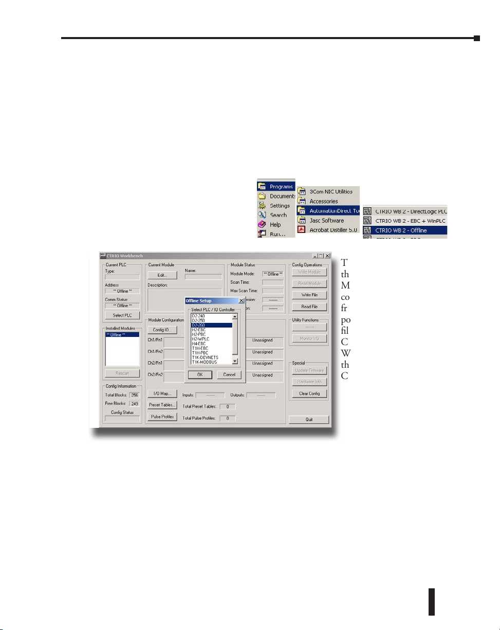
Chapter 4: CTRIO Workbench, Overview
Getting Started with CTRIO Workbench
Several paths are available to start CTRIO Workbench. All users will find CTRIO Workbench
at Start>Programs>AutomationDirect Tools>CTRIO Workbench. DirectSOFT users will find
CTRIO Workbench in the Utilities section of the DSLaunch Window.
Offline CTRIO Configuration
A complete CTRIO configuration file (.cwb) can be created Offline.
To launch the CTRIO Workbench 2 Offline version, go to Start>Programs>AutomationDirect
Tools>CTRIO WB2 - Offline.
In the Workbench Offline window, as
shown below, click on the Select PLC
button. Select desired PLC or interface
device.
The only limitations in
the Offline version are that
Monitor I/O is not enabled and
connecting to the CTRIO(2)
from the Offline utility is not
possible. Save the configuration
file to disk and connect to the
CTRIO(2) using the appropriate
Workbench support version,
then write the file to the
CTRIO(2).
Counter I/O User Manual, 3rd Ed., Rev. E
4–3
Page 97

Chapter 4: CTRIO Workbench, Overview
Online CTRIO Configuration
To configure the CTRIO(2) module Online, a CTRIO(2) must be installed in the PLC base
or Terminator I/O system, and the system power must be on. The PC communicates with the
CTRIO(2) module through the PLC or interface device port.
DirectSOFT Users
Connect the PC to the CPU, DCM or ECOM module.
If linked to a CPU through DirectSOFT, CTRIO
Workbench will start via the existing link. If disconnected
from the PLC and open CTRIO Workbench, a prompt
appears to establish a link to the CTRIO(2) module.
WinPLC, EBC and PLC>ERM>EBC Users
Connect to the PC with the RJ45 Ethernet port on the
WinPLC or EBC interface device directly or via hub, switch,
etc, (Connect to the ST-style
fiber optic port on the Hx-EBC-F
units).
Access the WinPLC and
EBC support version at
DirectSOFT users will find CTRIO Workbench in
the DSLaunch Window’s Utilities section.
4–4
Start>Programs>AutomationDirect Tools>CTRIO WB2 - EBC + WinPLC or select CTRIO
WB2 - EBC + WinPLC in the DirectSOFT Launch Window Utilities menu.
A prompt will appear to establish
an Ethernet link to the CTRIO(2)
module.
NOTE: WinPLCs will need to be given an IP
address before connecting with Workbench.
EBCs will need to have an address selected
by DIP Switch or via NetEdit before
connecting with Workbench.
Counter I/O User Manual, 3rd Ed., Rev. E
Page 98

Chapter 4: CTRIO Workbench, Overview
PBC Users
Connect PC to the RJ12 serial port on the PBC interface
device.
Access the PBC support version at
Start>Programs>AutomationDirect Tools>CTRIO WB2
- PBC or select CTRIO WB2 - PBC in the DirectSOFT
Launch Window Utilities menu.
A prompt appears to establish a serial link to the
CTRIO(2) module.
Select the PC serial port Workbench will
use to connect to the CTRIO(2) module.
Successful On-line Connection
Once connected to the CTRIO(2) module, the main window of CTRIO Workbench is enabled.
Here, select the CTRIO(2) module to configure by clicking on its slot number in the “Installed
Modules” box. In Workbench’s
Configuration dialog, after
successfully configuring the
module, toggle the CTRIO(2)
module between Program Mode
and Run Mode and enter the
Monitor I/O dialog.
Counter I/O User Manual, 3rd Ed., Rev. E
4–5
Page 99
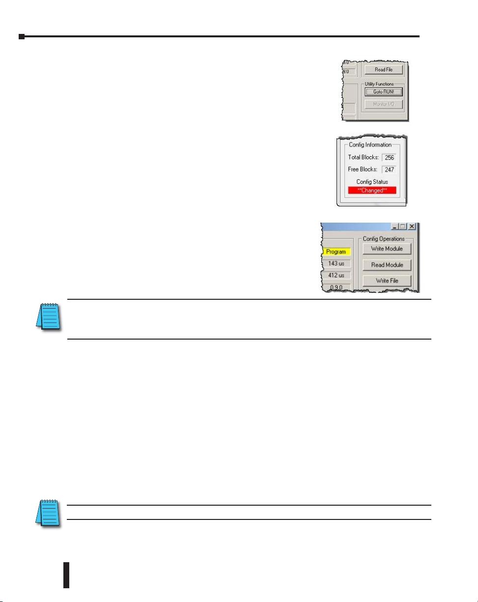
Chapter 4: CTRIO Workbench, Overview
Module Modes of Operation
On the CTRIO Workbench main window, a single button
toggles between Run Mode and Program Mode. The Module
Mode indicator will show which mode the module is in. Make
configuration changes in either Run Mode or Program Mode. To
save the configuration to the module, click “Write Module”, which
is only active in Program Mode.
In the lower left corner of the main Workbench dialog, is the Config
Status indicator. If the current configuration is different from the
CTRIO(2) and different from any saved files, the indicator will
display the word “Changed”. If the current configuration has been
written to the module or a file, the message will read “Same as
Module”, “Same as File”, or “Same as Both”.
Program Mode - Configuring the CTRIO(2) Module
After the configuration is created or changed in CTRIO
Workbench, it must be written to the CTRIO(2) module. This
is accomplished by returning to the main CTRIO Workbench
window and clicking on “Write Module”.
If the configuration was created using Workbench Offline
version, connect the PC to the CTRIO(2) module through the
CPU/controller and write the configuration to the module.
NOTE: Entering program mode takes the CTRIO(2) module offline. Input pulses are not read or processed
in Program mode, and all outputs are disabled. CPUs will hold last value in memory while the CTRIO(2) is
in Program Mode.
4–6
Run Mode - Start Processing I/O Pulses with the CTRIO(2) Module
Selecting Run Mode causes the CTRIO(2) module to begin processing pulses based on the
I/O configuration created.
In Run mode the CTRIO Workbench utility also allows monitoring to verify the proper
operation of inputs and outputs. Using Monitor I/O dialog, the count change, reset, etc. are
displayed. Monitor I/O is very useful for debugging and commissioning a new system. See
Chapter 8 “CTRIO Workbench, Monitor I/O” for more information.
The CTRIO mode follows the CPU mode. If the CPU is placed in Run Mode, the CTRIO(2)
module will also enter Run Mode (see note below). If the CPU is placed in STOP or
PROGRAM Mode, the CTRIO(2) will enter Program Mode. The CTRIO(2) also responds
to mode changes made in Workbench and can be placed in Run Mode while the CPU is in
Stop or Program Mode. The CTRIO(2) module responds to the most recent change whether
performed in Workbench or from the CPU.
NOTE: The CTRIO(2) module will not enter Run Mode if it does not have a valid configuration.
Counter I/O User Manual, 3rd Ed., Rev. E
Page 100

Chapter 4: CTRIO Workbench, Overview
Suspend (Output Reads) –
In Monitor I/O, Work Independently from the Controller
Another mode of operation is used in Monitor I/O. Suspended has the CTRIO(2) executing its
code, but ignoring commands initiated in ladder logic. Instead, commands are taken only from
Monitor I/O. Using Suspend prevents interference from the CPU while manually controlling
the CTRIO module. CTRIO Workbench offers to ‘Suspend output reads’ when Monitor I/O
is opened.
Upon closing Monitor I/O, CTRIO Workbench offers to ‘Enable output reads’. If left
Suspended, the Outputs address field will be highlighted yellow, as seen below.
Counter I/O User Manual, 3rd Ed., Rev. E
4–7
 Loading...