

Page 1
Hardware User Manual
EA1-TCL-M
®
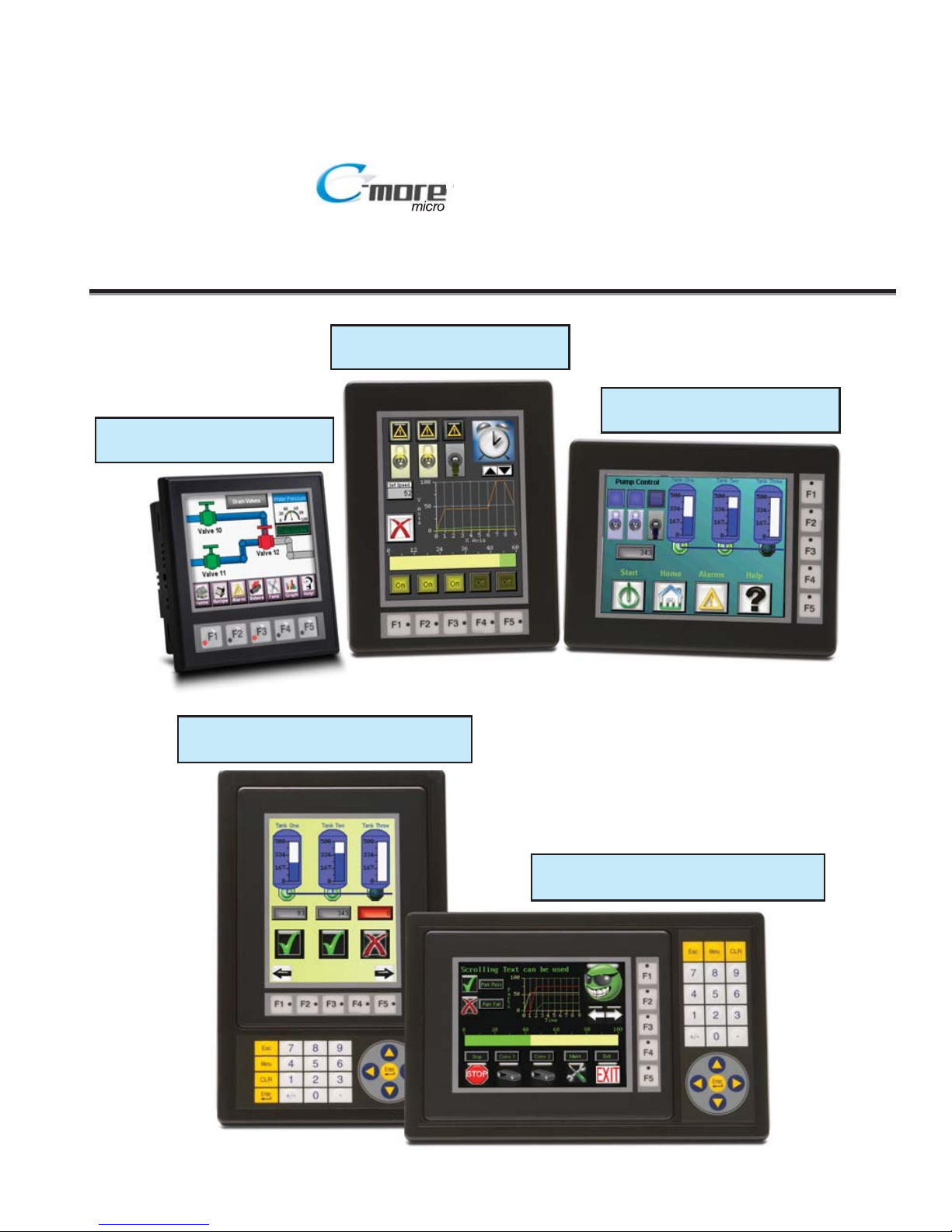
4-inch and 6-inch Color Micro-Graphic Panels
C-more 6” Color Micro-Graphic Panel
shown in Landscape Mode
C-more 6” Color Micro-Graphic Panel Installed in a
20-button Landscape Keypad Bezel EA-MG6-BZ2
C-more 6” Color Micro-Graphic Panel
shown in Portrait Mode
C-more 6” Color Micro-Graphic Panel Installed in a
21-button Portrait Keypad Bezel EA-MG6-BZ2P
C-more 4” Color Micro-Graphic Panel
shown in Landscape Mode
Page 2
Graphic Color Panels
HARDWARE USER MANUAL
Please include the Manual Number and the Manual Issue, both shown below,
when communicating with Technical Support regarding this publication.
Manual Number: EA1-TCL-M
Issue: 2nd Edition
Issue Date: 10/10
Publication History
Issue Date Description of Changes
1st Edition 12/09 Original issue
2nd Edition 10/10 Added 4-inch panel
®
EA1-T4CL & EA1-T6CL
Page 3

~ WARNING ~
Thank you for purchasing automation equipment from Automationdirect.com®, doing business as,
AutomationDirect. We want your new automation equipment to operate safely. Anyone who installs or
uses this equipment should read this publication (and any other relevant publications) before installing or
operating the equipment.
To minimize the risk of potential safety problems, you should follow all applicable local and national codes
that regulate the installation and operation of your equipment. These codes vary from area to area and
usually change with time. It is your responsibility to determine which codes should be followed, and to
verify that the equipment, installation, and operation is in compliance with the latest revision of these
codes.
At a minimum, you should follow all applicable sections of the National Fire Code, National Electrical
Code, and the codes of the National Electrical Manufacturer's Association (NEMA). There may be local
regulatory or government offices that can also help determine which codes and standards are necessary for
safe installation and operation.
Equipment damage or serious injury to personnel can result from the failure to follow all applicable codes
and standards. We do not guarantee the products described in this publication are suitable for your
particular application, nor do we assume any responsibility for your product design, installation, or
operation.
Our products are not fault-tolerant and are not designed, manufactured or intended for use or resale as online control equipment in hazardous environments requiring fail-safe performance, such as in the
operation of nuclear facilities, aircraft navigation or communication systems, air traffic control, direct life
support machines, or weapons systems, in which the failure of the product could lead directly to death,
personal injury, or severe physical or environmental damage ("High Risk Activities"). AutomationDirect
specifically disclaims any expressed or implied warranty of fitness for High Risk Activities.
For additional warranty and safety information, see the Terms and Conditions section of our catalog. If
you have any questions concerning the installation or operation of this equipment, or if you need
additional information, please call us at 770-844-4200.
This publication is based on information that was available at the time it was printed. At
AutomationDirect we constantly strive to improve our products and services, so we reserve the right to
make changes to the products and/or publications at any time without notice and without any obligation.
This publication may also discuss features that may not be available in certain revisions of the product.
Trademarks
This publication may contain references to products produced and/or offered by other companies. The
product and company names may be trademarked and are the sole property of their respective owners.
AutomationDirect disclaims any proprietary interest in the marks and names of others.
Copyright 2009-2010, Automationdirect.com®Incorporated
All Rights Reserved
No part of this manual shall be copied, reproduced, or transmitted in any way without the prior, written
consent of Automationdirect.com
®
Incorporated. AutomationDirect retains the exclusive rights to all
information included in this document.
Page 4

~
ADVERTENCIA
~
Gracias por comprar equipo de automatización de Automationdir ect.com®. Deseamos que su nuevo equipo de
automatización opere de manera segura. Cualquier persona que instale o use este equipo debe leer esta
publicación (y cualquier otra publicación pertinente) antes de instalar u operar el equipo.
Para reducir al mínimo el riesgo debido a problemas de seguridad, debe seguir todos los códigos de seguridad
locales o nacionales aplicables que regulan la instalación y operación de su equipo. Estos códigos varian de área
en área y usualmente cambian con el tiempo. Es su responsabilidad determinar cuales códigos deben ser
seguidos y verificar que el equipo, instalación y operación estén en cumplimiento con la revisión mas reciente
de estos códigos.
Como mínimo, debe seguir las secciones aplicables del Código Nacional de Incendio, Código Nacional
Eléctrico, y los códigos de (NEMA) la Asociación Nacional de Fabricantes Eléctricos de USA. Puede haber
oficinas de normas locales o del gobierno que pueden ayudar a determinar cuales códigos y normas son
necesarios para una instalación y operación segura.
Si no se siguen todos los códigos y normas aplicables, puede resultar en daños al equipo o lesiones serias a
personas. No garantizamos los productos descritos en esta publicación para ser adecuados para su aplicación en
particular, ni asumimos ninguna responsabilidad por el diseño de su producto, la instalación u operación.
Nuestros productos no son tolerantes a fallas y no han sido diseñados, fabricados o intencionados para uso o
reventa como equipo de control en línea en ambientes peligrosos que requieren una ejecución sin fallas, tales
como operación en instalaciones nucleares, sistemas de navegación aérea, o de comunicación, control de tráfico
aéreo, máquinas de soporte de vida o sistemas de armamentos en las cuales la falla del producto puede resultar
directamente en muerte, heridas personales, o daños físicos o ambientales severos ("Actividades de Alto Riesgo").
Automationdirect.com específicamente rechaza cualquier garantía ya sea expresada o implicada para
actividades de alto riesgo.
Para información adicional acerca de garantía e información de seguridad, vea la sección de Términos y
Condiciones de nuestro catálogo. Si tiene alguna pregunta sobre instalación u operación de este equipo, o si
necesita información adicional, por favor llámenos al número 770-844-4200 en Estados Unidos.
Esta publicación está basada en la información disponible al momento de impresión. En
Automationdirect.com nos esforzamos constantemente para mejorar nuestros productos y servicios, así que
nos reservamos el derecho de hacer cambios al producto y/o a las publicaciones en cualquier momento sin
notificación y sin ninguna obligación. Esta publicación también puede discutir características que no estén
disponibles en ciertas revisiones del producto
.
Marcas Registradas
Esta publicación puede contener referencias a productos producidos y/u ofrecidos por otras compañías. Los nombres de las
compañías y productos pueden tener marcas registradas y son propiedad única de sus respectivos dueños. Automationdirect.com,
renuncia cualquier interés propietario en las marcas y nombres de otros.
PROPIEDAD LITERARIA 2009-2010, AUTOMATIONDIRECT.COM®INCORPORATED
Todos los derechos reservados
No se permite copiar, reproducir, o transmitir de ninguna forma ninguna parte de este manual sin previo consentimiento por escrito de
Automationdirect.com
®
Incorprated. Automationdirect.com retiene los derechos exclusivos a toda la información incluida en este
documento. Los usuarios de este equipo pueden copiar este documento solamente para instalar, configurar y mantener el equipo
correspondiente. También las instituciones de enseñanza pueden usar este manual para propósitos educativos.
Page 5

~ AVERTISSEMENT ~
Nous vous remercions d'avoir acheté l'équipement d'automatisation de Automationdirect.com®, en faisant des
affaires comme, AutomationDirect. Nous tenons à ce que votre nouvel équipement d'automatisation fonctionne en
toute sécurité. Toute personne qui installe ou utilise cet équipement doit lire la présente publication (et toutes les
autres publications pertinentes) avant de l'installer ou de l'utiliser.
Afin de réduire au minimum le risque d'éventuels problèmes de sécurité, vous devez respecter tous les codes locaux et
nationaux applicables régissant l'installation et le fonctionnement de votre équipement. Ces codes diffèrent d'une
région à l'autre et, habituellement, évoluent au fil du temps. Il vous incombe de déterminer les codes à respecter et
de vous assurer que l'équipement, l'installation et le fonctionnement sont conformes aux exigences de la version la
plus récente de ces codes.
Vous devez, à tout le moins, respecter toutes les sections applicables du Code national de prévention des incendies,
du Code national de l'électricité et des codes de la National Electrical Manufacturer's Association (NEMA). Des
organismes de réglementation ou des services gouvernementaux locaux peuvent également vous aider à déterminer
les codes ainsi que les normes à respecter pour assurer une installation et un fonctionnement sûrs.
L'omission de respecter la totalité des codes et des normes applicables peut entraîner des dommages à l'équipement
ou causer de graves blessures au personnel. Nous ne garantissons pas que les produits décrits dans cette publication
conviennent à votre application particulière et nous n'assumons aucune responsabilité à l'égard de la conception, de
l'installation ou du fonctionnement de votre produit.
Nos produits ne sont pas insensibles aux défaillances et ne sont ni conçus ni fabriqués pour l'utilisation ou la revente
en tant qu'équipement de commande en ligne dans des environnements dangereux nécessitant une sécurité absolue,
par exemple, l'exploitation d'installations nucléaires, les systèmes de navigation aérienne ou de communication, le
contrôle de la circulation aérienne, les équipements de survie ou les systèmes d'armes, pour lesquels la défaillance du
produit peut provoquer la mort, des blessures corporelles ou de graves dommages matériels ou environnementaux
(«activités à risque élevé»). La société AutomationDirect nie toute garantie expresse ou implicite d'aptitude à
l'emploi en ce qui a trait aux activités à risque élevé.
Pour des renseignements additionnels touchant la garantie et la sécurité, veuillez consulter la section Modalités et
conditions de notre documentation. Si vous avez des questions au sujet de l'installation ou du fonctionnement de cet
équipement, ou encore si vous avez besoin de renseignements supplémentaires, n'hésitez pas à nous téléphoner au
770-844-4200.
Cette publication s'appuie sur l'information qui était disponible au moment de l'impression. À la société
AutomationDirect, nous nous efforçons constamment d'améliorer nos produits et services. C'est pourquoi nous
nous réservons le droit d'apporter des modifications aux produits ou aux publications en tout temps, sans préavis ni
quelque obligation que ce soit. La présente publication peut aussi porter sur des caractéristiques susceptibles de ne
pas être offertes dans certaines versions révisées du produit.
Marques de commerce
La présente publication peut contenir des références à des produits fabriqués ou offerts par d'autres entreprises. Les
désignations des produits et des entreprises peuvent être des marques de commerce et appartiennent exclusivement à
leurs propriétaires respectifs. AutomationDirect nie tout intérêt dans les autres marques et désignations.
Copyright 2009-2010, Automationdirect.com®Incorporated
Tous droits réservés
Nulle partie de ce manuel ne doit être copiée, reproduite ou transmise de quelque façon que ce soit sans le
consentement préalable écrit de la société Automationdirect.com
®
Incorporated. AutomationDirect conserve les
droits exclusifs à l'égard de tous les renseignements contenus dans le présent document.
Page 6

TABL E OF CON TEN TS
Chapter 1: Getting Started . . . . . . . . . . . . . . . . . . . . . . . . . . . . . . . . .1–1
Introduction . . . . . . . . . . . . . . . . . . . . . . . . . . . . . . . . . . . . . . . . . . . . . . . . . . . . . . .1–2
Conventions Used . . . . . . . . . . . . . . . . . . . . . . . . . . . . . . . . . . . . . . . . . . . . . . . . . . .1–3
Product Overview - EA1-T4CL . . . . . . . . . . . . . . . . . . . . . . . . . . . . . . . . . . . . . . . . . .1–4
Product Overview - EA1-T6CL . . . . . . . . . . . . . . . . . . . . . . . . . . . . . . . . . . . . . . . . . .1–5
Agency Approvals . . . . . . . . . . . . . . . . . . . . . . . . . . . . . . . . . . . . . . . . . . . . . . . . . . .1–5
Part Number Key . . . . . . . . . . . . . . . . . . . . . . . . . . . . . . . . . . . . . . . . . . . . . . . . . . .1–6
Product Label Examples . . . . . . . . . . . . . . . . . . . . . . . . . . . . . . . . . . . . . . . . . . . . . .1–6
Serial Number and Date Code format . . . . . . . . . . . . . . . . . . . . . . . . . . . . . . . . . . .1–6
Quick Start Steps . . . . . . . . . . . . . . . . . . . . . . . . . . . . . . . . . . . . . . . . . . . . . . . . . . . .1–7
Step 1 – Unpack and Inspect . . . . . . . . . . . . . . . . . . . . . . . . . . . . . . . . . . . . . . . . . .1–7
Step 2 – Install Optional Hardware Accessories . . . . . . . . . . . . . . . . . . . . . . . . . . . .1–8
Step 3 – Become Familiar with Available Communication Ports . . . . . . . . . . . . . . . .1–9
Step 4 – Install C-more Color Micro-Graphic Panel . . . . . . . . . . . . . . . . . . . . . . . .1–10
Enclosure Clearances . . . . . . . . . . . . . . . . . . . . . . . . . . . . . . . . . . . . . . . . . . . . . . .1–12
Step 5 – Install the Programming Software and Develop a Project . . . . . . . . . . . .1–13
Step 6 – Connect C-more Color Micro-Graphic Panel to Computer . . . . . . . . . . . .1–14
Step 7 – Providing Power to the C-more Color Micro-Graphic Panel . . . . . . . . . . .1–15
Step 8 – Accessing the C-more Color Micro-Graphic Panel Setup Screens . . . . . . .1–16
Step 9 – Choose C-more Color Micro-Graphic Panel to PLC Protocol & Cables . . .1–17
Step 10 – Connect C-more Color Micro-Graphic Panel to PLC . . . . . . . . . . . . . . . .1–18
Page 7

Chapter 2: Specifications . . . . . . . . . . . . . . . . . . . . . . . . . . . . . . . . . . .2–1
Available Models . . . . . . . . . . . . . . . . . . . . . . . . . . . . . . . . . . . . . . . . . . . . . . . . . . . .2–2
EA1-T4CL Specifications . . . . . . . . . . . . . . . . . . . . . . . . . . . . . . . . . . . . . . . . . . . . . .2–3
EA1-T6CL Specifications . . . . . . . . . . . . . . . . . . . . . . . . . . . . . . . . . . . . . . . . . . . . . .2–5
EA1-T4CL Panel Dimensions . . . . . . . . . . . . . . . . . . . . . . . . . . . . . . . . . . . . . . . . . . .2–7
EA1-T6CL Panel Dimensions . . . . . . . . . . . . . . . . . . . . . . . . . . . . . . . . . . . . . . . . . . .2–8
Communications Port . . . . . . . . . . . . . . . . . . . . . . . . . . . . . . . . . . . . . . . . . . . . . . . .2–9
Chemical Compatibility . . . . . . . . . . . . . . . . . . . . . . . . . . . . . . . . . . . . . . . . . . . . . .2–10
Chapter 3: Accessories . . . . . . . . . . . . . . . . . . . . . . . . . . . . . . . . . . . . .3–1
Accessories . . . . . . . . . . . . . . . . . . . . . . . . . . . . . . . . . . . . . . . . . . . . . . . . . . . . . . . .3–2
C-more Micro-Graphic Programming Software . . . . . . . . . . . . . . . . . . . . . . . . . . . .3–3
20-Button Landscape (Horizontal) Keypad Bezel for 6-inch Panels . . . . . . . . . . . .3–6
21-Button Portrait (Vertical) Keypad Bezel for 6-inch Panels . . . . . . . . . . . . . . . . .3–9
D-SUB 15-pin 90-degree Communication Port Adapter . . . . . . . . . . . . . . . . . . . .3–12
D-SUB 15-pin to Terminal Block Adapter . . . . . . . . . . . . . . . . . . . . . . . . . . . . . . . .3–12
Clear Screen Overlay . . . . . . . . . . . . . . . . . . . . . . . . . . . . . . . . . . . . . . . . . . . . . . . .3–13
Chapter 4: Installation and Wiring . . . . . . . . . . . . . . . . . . . . . . . . . . .4–1
Safety Guidelines . . . . . . . . . . . . . . . . . . . . . . . . . . . . . . . . . . . . . . . . . . . . . . . . . . .4–2
Introduction . . . . . . . . . . . . . . . . . . . . . . . . . . . . . . . . . . . . . . . . . . . . . . . . . . . . . . .4–3
Panel Cutout Dimensions . . . . . . . . . . . . . . . . . . . . . . . . . . . . . . . . . . . . . . . . . . . . .4–4
Wiring Guidelines . . . . . . . . . . . . . . . . . . . . . . . . . . . . . . . . . . . . . . . . . . . . . . . . . . .4–5
Chapter 5: System Setup Screens . . . . . . . . . . . . . . . . . . . . . . . . . . . .5–1
Introduction . . . . . . . . . . . . . . . . . . . . . . . . . . . . . . . . . . . . . . . . . . . . . . . . . . . . . . .5–2
Accessing the System Setup Screens . . . . . . . . . . . . . . . . . . . . . . . . . . . . . . . . . . . .5–3
System Setup Screens Flowchart . . . . . . . . . . . . . . . . . . . . . . . . . . . . . . . . . . . . . . .5–4
Setup Menu . . . . . . . . . . . . . . . . . . . . . . . . . . . . . . . . . . . . . . . . . . . . . . . . . . . . . . . .5–5
ii
Table of Contents
®
EA1-TCL-M Hardware User Manual, 2nd Ed., 10/10
Page 8

Information Menu . . . . . . . . . . . . . . . . . . . . . . . . . . . . . . . . . . . . . . . . . . . . . . . . . . .5–6
Setting Menu . . . . . . . . . . . . . . . . . . . . . . . . . . . . . . . . . . . . . . . . . . . . . . . . . . . . . .5–7
Brightness . . . . . . . . . . . . . . . . . . . . . . . . . . . . . . . . . . . . . . . . . . . . . . . . . . . . . . . .5–7
Touch/Key Beep . . . . . . . . . . . . . . . . . . . . . . . . . . . . . . . . . . . . . . . . . . . . . . . . . . . .5–8
Calibration . . . . . . . . . . . . . . . . . . . . . . . . . . . . . . . . . . . . . . . . . . . . . . . . . . . . . . . .5–9
Clear User Memory . . . . . . . . . . . . . . . . . . . . . . . . . . . . . . . . . . . . . . . . . . . . . . . .5–10
Reset to Factory Default . . . . . . . . . . . . . . . . . . . . . . . . . . . . . . . . . . . . . . . . . . . . .5–10
Hourglass . . . . . . . . . . . . . . . . . . . . . . . . . . . . . . . . . . . . . . . . . . . . . . . . . . . . . . . .5–11
Rotation . . . . . . . . . . . . . . . . . . . . . . . . . . . . . . . . . . . . . . . . . . . . . . . . . . . . . . . . .5–12
Test Menu . . . . . . . . . . . . . . . . . . . . . . . . . . . . . . . . . . . . . . . . . . . . . . . . . . . . . . . .5–13
Serial Port2 - Loop Back Test . . . . . . . . . . . . . . . . . . . . . . . . . . . . . . . . . . . . . . . . .5–14
PLC Enquiry Test . . . . . . . . . . . . . . . . . . . . . . . . . . . . . . . . . . . . . . . . . . . . . . . . . .5–15
Buzzer Test . . . . . . . . . . . . . . . . . . . . . . . . . . . . . . . . . . . . . . . . . . . . . . . . . . . . . .5–15
Touch Panel Test . . . . . . . . . . . . . . . . . . . . . . . . . . . . . . . . . . . . . . . . . . . . . . . . . .5–16
Display Test . . . . . . . . . . . . . . . . . . . . . . . . . . . . . . . . . . . . . . . . . . . . . . . . . . . . . .5–16
Exit . . . . . . . . . . . . . . . . . . . . . . . . . . . . . . . . . . . . . . . . . . . . . . . . . . . . . . . . . . . . . .5–17
Chapter 6: PLC Communications . . . . . . . . . . . . . . . . . . . . . . . . . . . . .6–1
Introduction . . . . . . . . . . . . . . . . . . . . . . . . . . . . . . . . . . . . . . . . . . . . . . . . . . . . . . .6–2
C-more Micro-Graphic Communication Ports . . . . . . . . . . . . . . . . . . . . . . . . . . . . .6–4
DirectLOGIC PLCs Password Protection . . . . . . . . . . . . . . . . . . . . . . . . . . . . . . . . . .6–5
Compatibility and Connection Charts . . . . . . . . . . . . . . . . . . . . . . . . . . . . . . . . . . .6–5
AutomationDirect Controllers . . . . . . . . . . . . . . . . . . . . . . . . . . . . . . . . . . . . . . . . .6–6
RS-422A/RS-485A Communications . . . . . . . . . . . . . . . . . . . . . . . . . . . . . . . . . . . . .6–6
Allen-Bradley . . . . . . . . . . . . . . . . . . . . . . . . . . . . . . . . . . . . . . . . . . . . . . . . . . . . . .6–6
GE, Mitsubishi, Omron, Modicon and Siemens . . . . . . . . . . . . . . . . . . . . . . . . . . . .6–6
How to use the Compatibility and Connection Charts . . . . . . . . . . . . . . . . . . . . . . .6–7
Cables from AutomationDirect . . . . . . . . . . . . . . . . . . . . . . . . . . . . . . . . . . . . . . . .6–14
Cables from AutomationDirect – Wiring Diagrams . . . . . . . . . . . . . . . . . . . . . . . .6–16
User Constructed Cables – Wiring Diagrams . . . . . . . . . . . . . . . . . . . . . . . . . . . . .6–24
RS-422A Multi-Drop Wiring Diagram Example . . . . . . . . . . . . . . . . . . . . . . . . . . .6–36
RS-485A Multi-Drop Wiring Diagram Example . . . . . . . . . . . . . . . . . . . . . . . . . . .6–38
iii
Table of Contents
EA1-TCL-M Hardware User Manual, 2nd Ed., 10/10
®
Page 9

Chapter 7: Maintenance . . . . . . . . . . . . . . . . . . . . . . . . . . . . . . . . . . . .7–1
Project Backup . . . . . . . . . . . . . . . . . . . . . . . . . . . . . . . . . . . . . . . . . . . . . . . . . . . . . .7–2
Check Operating Environment . . . . . . . . . . . . . . . . . . . . . . . . . . . . . . . . . . . . . . . . .7–2
Check Operating Voltage . . . . . . . . . . . . . . . . . . . . . . . . . . . . . . . . . . . . . . . . . . . . .7–2
Check Transmit and Receive Indicators . . . . . . . . . . . . . . . . . . . . . . . . . . . . . . . . . .7–3
Check Physical Conditions . . . . . . . . . . . . . . . . . . . . . . . . . . . . . . . . . . . . . . . . . . . .7–3
Run Tests under the System Setup Screens . . . . . . . . . . . . . . . . . . . . . . . . . . . . . . .7–4
Check Settings under the System Setup Screens . . . . . . . . . . . . . . . . . . . . . . . . . .7–5
Cleaning the Display Screen . . . . . . . . . . . . . . . . . . . . . . . . . . . . . . . . . . . . . . . . . . .7–5
Check Project Functionality . . . . . . . . . . . . . . . . . . . . . . . . . . . . . . . . . . . . . . . . . . .7–6
Checks from the C-more Micro-Graphic Programming Software . . . . . . . . . . . . . .7–6
Chapter 8: Troubleshooting . . . . . . . . . . . . . . . . . . . . . . . . . . . . . . . . .8–1
C-more Micro-Graphic Panel does not Power up . . . . . . . . . . . . . . . . . . . . . . . . . . .8–2
Display is Blank . . . . . . . . . . . . . . . . . . . . . . . . . . . . . . . . . . . . . . . . . . . . . . . . . . . . .8–2
Display is Dim . . . . . . . . . . . . . . . . . . . . . . . . . . . . . . . . . . . . . . . . . . . . . . . . . . . . . .8–3
No User Program . . . . . . . . . . . . . . . . . . . . . . . . . . . . . . . . . . . . . . . . . . . . . . . . . . .8–3
Lost Firmware – Red ‘Update Mode’ Screen Displayed . . . . . . . . . . . . . . . . . . . . . .8–4
Updating Firmware . . . . . . . . . . . . . . . . . . . . . . . . . . . . . . . . . . . . . . . . . . . . . . . . . .8–4
No Communications between Panel and PC (Personal Computer) . . . . . . . . . . . .8–5
No Communications between Panel and PLC . . . . . . . . . . . . . . . . . . . . . . . . . . . . .8–7
Panel & PLC Error Codes . . . . . . . . . . . . . . . . . . . . . . . . . . . . . . . . . . . . . . . . . . . . .8–8
C-more Micro-Graphic Panel Runtime Errors . . . . . . . . . . . . . . . . . . . . . . . . . . . . . .8–9
Reset to Factory Default . . . . . . . . . . . . . . . . . . . . . . . . . . . . . . . . . . . . . . . . . . . . .8–10
Electrical Noise Problems . . . . . . . . . . . . . . . . . . . . . . . . . . . . . . . . . . . . . . . . . . . .8–10
Chapter 9: Replacement Parts . . . . . . . . . . . . . . . . . . . . . . . . . . . . . . .9–1
Replacement Parts Overview . . . . . . . . . . . . . . . . . . . . . . . . . . . . . . . . . . . . . . . . . .9–2
Replacement Parts . . . . . . . . . . . . . . . . . . . . . . . . . . . . . . . . . . . . . . . . . . . . . . . . . .9–2
Customizing the Function Keys Insert Label . . . . . . . . . . . . . . . . . . . . . . . . . . . . . .9–3
iv
Table of Contents
®
EA1-TCL-M Hardware User Manual, 2nd Ed., 10/10
Page 10

Appendix A: PLC Protocol Error Codes . . . . . . . . . . . . . . . . . . . . . . . .A–1
Introduction . . . . . . . . . . . . . . . . . . . . . . . . . . . . . . . . . . . . . . . . . . . . . . . . . . . . . . .A–2
C-more Micro-Graphic Panel Error Code Table . . . . . . . . . . . . . . . . . . . . . . . . . . . .A–3
Modbus Protocols Error Code P499 Explanation . . . . . . . . . . . . . . . . . . . . . . . . . .A–4
AutomationDirect CLICK . . . . . . . . . . . . . . . . . . . . . . . . . . . . . . . . . . . . . . . . . . . . .A–4
AutomationDirect DirectLOGIC - Modbus (Koyo) . . . . . . . . . . . . . . . . . . . . . . . . . .A–4
Modicon Modbus RTU . . . . . . . . . . . . . . . . . . . . . . . . . . . . . . . . . . . . . . . . . . . . . .A–4
Entivity Modbus RTU . . . . . . . . . . . . . . . . . . . . . . . . . . . . . . . . . . . . . . . . . . . . . . . .A–4
Productivity3000 Error Code P499 . . . . . . . . . . . . . . . . . . . . . . . . . . . . . . . . . . . . . .A–5
DirectLOGIC Error Code P499 Explanation . . . . . . . . . . . . . . . . . . . . . . . . . . . . . . .A–6
DirectLOGIC – K-Sequence PLC Error Code Table . . . . . . . . . . . . . . . . . . . . . . . . . .A–6
DirectLOGIC – DirectNET PLC Error Codes . . . . . . . . . . . . . . . . . . . . . . . . . . . . . . .A–6
Allen-Bradley Error Code P499 Explanation . . . . . . . . . . . . . . . . . . . . . . . . . . . . . .A–7
Allen-Bradley DF1 Protocol – PLC Error Code Tables . . . . . . . . . . . . . . . . . . . . . . .A–8
Allen-Bradley DH485 Protocol – PLC Error Code Tables . . . . . . . . . . . . . . . . . . . .A–10
GE Error Code P499 Explanation . . . . . . . . . . . . . . . . . . . . . . . . . . . . . . . . . . . . . .A–12
GE SNPX Protocol – PLC Error Code Tables . . . . . . . . . . . . . . . . . . . . . . . . . . . . .A–13
Mitsubishi FX Protocol – PLC Error Codes . . . . . . . . . . . . . . . . . . . . . . . . . . . . . . .A–22
Mitsubishi Q / QnA Series – PLC Error Codes . . . . . . . . . . . . . . . . . . . . . . . . . . . .A–22
Omron Error Code P499 Explanation . . . . . . . . . . . . . . . . . . . . . . . . . . . . . . . . . .A–24
Omron Host Link Protocol – PLC Error Code Table . . . . . . . . . . . . . . . . . . . . . . . .A–25
Omron FINS Protocol – PLC Error Code Table . . . . . . . . . . . . . . . . . . . . . . . . . . . .A–26
Siemens Error Code P499 Explanation . . . . . . . . . . . . . . . . . . . . . . . . . . . . . . . . .A–29
Siemens PPI Protocol – PLC Error Code Table . . . . . . . . . . . . . . . . . . . . . . . . . . . .A–30
Appendix B: C-more Micro-Graphic Panel Runtime Errors . . . . . . . . .B–1
Introduction . . . . . . . . . . . . . . . . . . . . . . . . . . . . . . . . . . . . . . . . . . . . . . . . . . . . . . .B–2
Runtime Errors . . . . . . . . . . . . . . . . . . . . . . . . . . . . . . . . . . . . . . . . . . . . . . . . . . . . .B–2
Index
v
Table of Contents
EA1-TCL-M Hardware User Manual, 2nd Ed., 10/10
®
Page 11

1
1
GETTING STARTE D
CH
CHAPTER
CHAPTER
In This Chapter...
Introduction . . . . . . . . . . . . . . . . . . . . . . . . . . . . . . . . . . . . . . . . . . . . . . . . . . . . . . .1–2
Conventions Used . . . . . . . . . . . . . . . . . . . . . . . . . . . . . . . . . . . . . . . . . . . . . . . . . . .1–3
Product Overview - EA1-T4CL . . . . . . . . . . . . . . . . . . . . . . . . . . . . . . . . . . . . . . . . . .1–4
Product Overview - EA1-T6CL . . . . . . . . . . . . . . . . . . . . . . . . . . . . . . . . . . . . . . . . . .1–5
Agency Approvals . . . . . . . . . . . . . . . . . . . . . . . . . . . . . . . . . . . . . . . . . . . . . . . . . . .1–5
Part Number Key . . . . . . . . . . . . . . . . . . . . . . . . . . . . . . . . . . . . . . . . . . . . . . . . . . .1–6
Product Label Examples . . . . . . . . . . . . . . . . . . . . . . . . . . . . . . . . . . . . . . . . . . . . . .1–6
Serial Number and Date Code format . . . . . . . . . . . . . . . . . . . . . . . . . . . . . . . . . . .1–6
Quick Start Steps . . . . . . . . . . . . . . . . . . . . . . . . . . . . . . . . . . . . . . . . . . . . . . . . . . . .1–7
Step 1 – Unpack and Inspect . . . . . . . . . . . . . . . . . . . . . . . . . . . . . . . . . . . . . . . . . .1–7
Step 2 – Install Optional Hardware Accessories . . . . . . . . . . . . . . . . . . . . . . . . . . . .1–8
Step 3 – Become Familiar with Available Communication Ports . . . . . . . . . . . . . . . .1–9
Step 4 – Install C-more Color Micro-Graphic Panel . . . . . . . . . . . . . . . . . . . . . . . .1–10
Enclosure Clearances . . . . . . . . . . . . . . . . . . . . . . . . . . . . . . . . . . . . . . . . . . . . . . .1–12
Step 5 – Install the Programming Software and Develop a Project . . . . . . . . . . . .1–13
Step 6 – Connect C-more Color Micro-Graphic Panel to Computer . . . . . . . . . . . .1–14
Step 7 – Providing Power to the C-more Color Micro-Graphic Panel . . . . . . . . . . .1–15
Step 8 – Accessing the C-more Color Micro-Graphic Panel Setup Screens . . . . . . .1–16
Step 9 – Choose C-more Color Micro-Graphic Panel to PLC Protocol & Cables . . .1–17
Step 10 – Connect C-more Color Micro-Graphic Panel to PLC . . . . . . . . . . . . . . . .1–18
Page 12

Introduction
The Purpose of this Manual
Thank you for purchasing from our C-more®Micro-Graphic family of products. This manual
describes AutomationDirect.com’s C-more Color Micro-Graphic panels, specifications, included
components and available accessories and provides you with important information for
installation, connectivity and setup. The manual shows you how to install, wire and use the
products. It also helps you understand how to interface the panels to other devices in a control
system.
This user manual contains important information for personnel who will install the panels and
accessories, and for the personnel who will be programming the panel. If you understand
control systems making use of operating interfaces such as the C-more Micro-Graphic panels,
our user manuals will provide all the information you need to get, and keep, your system up and
running.
Supplemental Manuals
If you are familiar with industrial control type devices, you may be able to get up and running
with just the aide of the Quick Start Guide that is included with each panel. You may also refer
to the online help that is available in the C-more Micro-Graphic programming software.
Technical Support
We strive to make our manuals the best in the industry. We rely on your feedback to let us know
if we are reaching our goal. If you cannot find the solution to your particular application, or, if
for any reason you need technical assistance, please call us at:
770–844–4200
Our technical support group will work with you to answer your questions. They are available
Monday through Friday from 9:00 A.M. to 6:00 P.M. Eastern Time. We also encourage you to
visit our web site where you can find technical and non-technical information about our
products and our company.
http://c-moremicro.automationdirect.com
EA1-TCL-M Hardware User Manual, 2nd Ed., 10/10
1–2
Chapter 1: Getting Started
1
®
Page 13
Conventions Used
When you see the “notepad” icon in the left-hand margin, the paragraph to its immediate right will be a
special note. The word NOTE: in boldface will mark the beginning of the text.
When you see the “exclamation mark” icon in the left-hand margin, the paragraph to its immediate
right will be a warning. This information could prevent injury, loss of property, or even death (in
extreme cases). The word WARNING: in boldface will mark the beginning of the text.
Key Topics for Each Chapter
The beginning of each chapter will list the key topics
that can be found in that chapter.
EA1-TCL-M Hardware User Manual, 2nd Ed., 10/10
1–3
Chapter 1: Getting Started
1
®
Getting Started
CHAPTER
1
In This Chapter...
............................ ....................................1-2
...................................... ....................................1-4Spec fications
General Information
Page 14

Product Overview - EA1-T4CL
The C-more 4” Color Micro-Graphic panel has a 4.1-inch TFT LCD color 320 x 240 dot
display with an LED backlight. It features five user-defined function keys, each key with a
user-defined red LED indicator. The panel displays up to 40 lines by 80 characters of static
text and up to 30 lines by 40 characters of dynamic text with embedded variables and phrases
mixed with graphics at landscape orientation. Portrait orientation can display 60 characters
and 53 lines of static text and 40 lines by 40 characters of dynamic text. EA1-T4CL is rated
UL for use on a flat surface of Type 4X enclosure (for indoor use only). The C-more 4”
Micro-Graphic panels are powered from a 12-24 VDC power supply during operation, or can
be powered in low power mode through the USB port from a PC during programming.
Other features include:
• 3276 KB memory
• USB Type B programming port.
• Built in 15-pin serial communications port (RS-232/422/485)
• Optional replaceable clear screen overlay
• Built in Alarm Control setup that activates beep, backlight flash, customized alarm banner,
and red LED blinking
• Up to 999 screens, limited only by memory usage
• 0 to 50 °C (32 to 122 °F) operating temperature range
• UL, cUL & CE agency approvals (see next page for details)
• 2-year warranty from date of purchase
EA1-TCL-M Hardware User Manual, 2nd Ed., 10/10
1–4
Chapter 1: Getting Started
1
®
EA1-T4CL
Page 15
EA1-TCL-M Hardware User Manual, 2nd Ed., 10/10
1–5
Chapter 1: Getting Started
1
®
Product Overview - EA1-T6CL
The C-more 6” Color Micro-Graphic panel has a 5.7-inch TFT LCD color 320 x 240 dot
display with an LED backlight. It features five user-defined function keys, each key with a
user-defined red LED indicator. The panel displays up to 40 lines by 80 characters of static
text and up to 40 lines by 40 characters of dynamic text with embedded variables and phrases
mixed with graphics at landscape orientation. Portrait orientation can display 60 characters
and 53 lines of static text and 40 lines by 40 characters of dynamic text. EA1-T6CL is rated
UL for use on a flat surface of Type 1, 4X enclosure (for indoor use only). The C-more 6”
Micro-Graphic panels are powered from a 12-24 VDC power supply during operation, or can
be powered in low power mode through the USB port from a PC during programming.
Other features include:
• 3276 KB memory
• USB Type B programming port.
• Built in 15-pin serial communications port (RS-232/422/485)
• 2 optional keypad bezels, 20-button landscape and 21-button portrait mount
• Optional replaceable clear screen overlay
• Built in Alarm Control setup that activates beep, backlight flash, customized alarm banner, and red
LED blinking
• Up to 999 screens, limited only by memory usage
• 0 to 50 °C (32 to 122 °F) operating temperature range
• UL, cUL & CE agency approvals (see below for details)
• 2-year warranty from date of purchase
Agency Approvals
EA1-T6CL
shown in Portrait (Vertical) mode
UL/CUL/CE Certification Numbers
Name UL/CUL UL508 CE ISO-9000
C-more Micro-Graphic Panels
& Accessories
E157382 E157382 EN61131-2 Yes
U
L
C
US
R
EA1-T6CL
shown in Landscape (Horizontal) mode
Page 16
Part Number Key
Panel Part Number Key
The C-more Micro-Graphic panel part numbers consist of the following:
Bezel Part Number Key
The optional C-more 6” Micro-Graphic keypad bezel part numbers consist of the following:
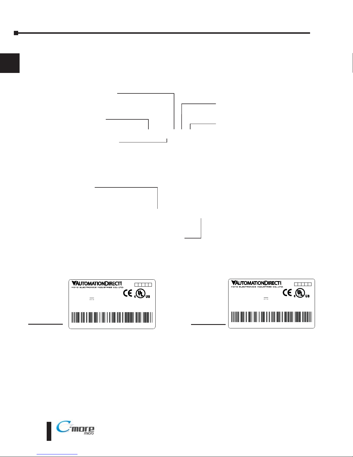
Product Label Examples
Serial Number and Date Code format
EA1-TCL-M Hardware User Manual, 2nd Ed., 10/10
1–6
Chapter 1: Getting Started
1
®
EA1-T6CL
Display Type:
S: STN
T: TFT
Display Color:
M: Monochrome
C: Color
Display Size:
3: 3.1”
4: 4.1“
6: 5.7”
Backlight Type:
L: LED
Series Name:
EA1: C more Micro Graphic
LISTED
7M17
cod
Date code:****
5 4 3 2 1 0
R01.
MADE IN CHINA
EA1-T6CL + serial number
OD C
MODEL:EA1-T6CL
U
INPUT:12-24V 6.5W
D O
IND.CONT.EQ.
EA-MG6-XXXX
Module Type:
BZ2: 20 Key Bezel for landscape mode
BZ2P: 21 Key Bezel for portrait mode
Series Name:
EA MG6: C more 6” Micro Graphic
Bezel Option Module
EA1-T6CL
YYMF
YY: Year (07 99 --- e.g. 07 2007)
M: Month (1 9, X, Y, Z --- e.g. X Oct.)
DD: Day (1 31)
F: Manufacturing Site (0 9, A Z)
NNN: Sequence number for the date listed (000 999)
Serial Number =
[Part Number]+[YYMDDFNNN]
Date Code =
0
INPUT:12-24V 0.19-0.38A Class2
LISTED
7M17
Date code:****
5 4 3 2
1
R**.
D
MADE IN CHINA
EA1-T4CL + serial number
OD
MODEL:EA1-T4CL
IND.CONT.EQ.
EA1-T4CL
Page 17
EA1-TCL-M Hardware User Manual, 2nd Ed., 10/10
1–7
Chapter 1: Getting Started
1
®
Quick Start Steps
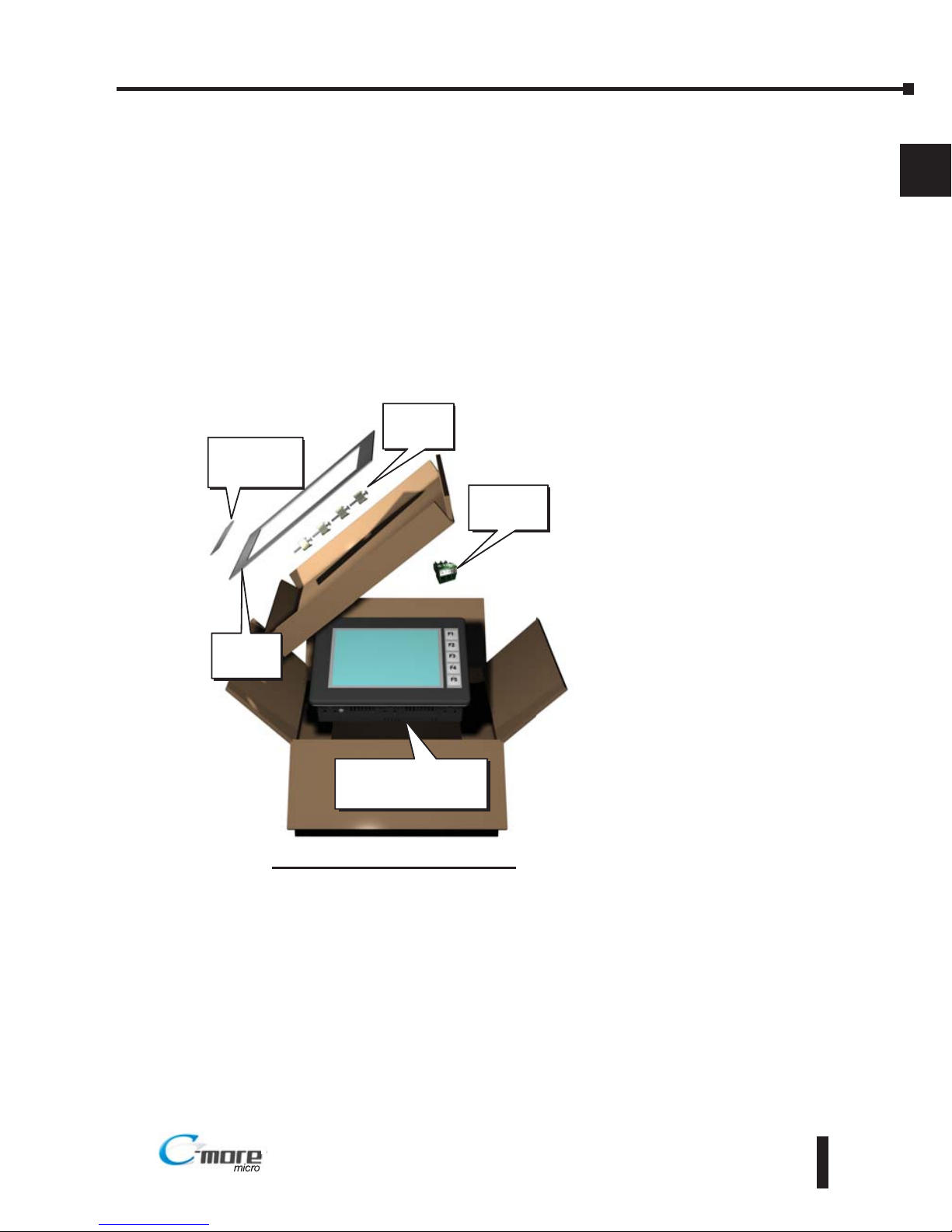
Step 1 – Unpack and Inspect
a.) Unpack the C-more Color Micro-Graphic panel from its shipping carton. Included in the
carton are the following:
• C-more Color Micro-Graphic panel
• DC power connector
• cutout template
• mounting clips
• gasket
• function key label inserts
• Quick Start Guide
b.) Unpack any accessories that have
been ordered, such as:
Keypad Bezel, programming
cable, PLC communications
cable, etc.
c.) Inspect all equipment for
completeness. If anything is
missing or damaged,
immediately call the
AutomationDirect®returns
department @ 1-800-633-0405.
Shipping Carton Contents
Cutout
Template
Function Key
Label Inserts
Mounting
Clips
C-more Color
Micro-Graphic
Panel
DC Power
Connector
Page 18
EA1-TCL-M Hardware User Manual, 2nd Ed., 10/10
1–8
Chapter 1: Getting Started
1
®
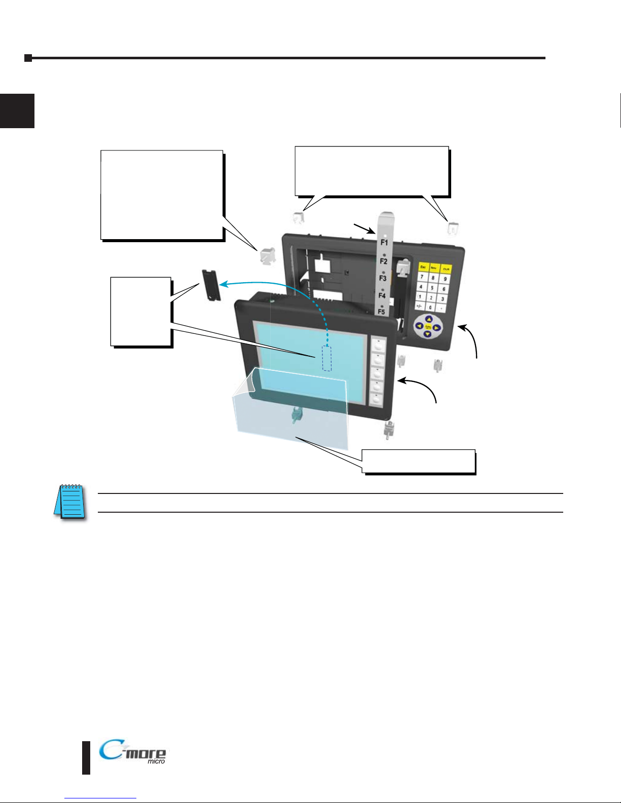
Step 2 – Install Optional Hardware Accessories (EA1-T6CL)
The C-more 6” Micro-Graphic panel can be mounted in an optional 20 or 21 button keypad
bezel. Below is an example of a C-more 6” Micro-Graphic panel being assembled with the
optional EA-MG6-BZ2 20-button Keypad Bezel.
C-more Color 6 Inch
Micro-Graphic Panel
20 Button
Keypad Bezel
EA MG6 BZ2
1. Remove
Expansion
Connector
Protective
Cover from
rear of
panel.
2. Use the (4) Panel Mounting
Clips, EA-MG-BZ2-BRK,
that are supplied with the
panel, to secure panel to
keypad bezel and compress
the gasket between the
panel and the keypad bezel.
Tighten screws to a torque
of 21-28 oz-in [0.15-0.2 Nm].
3. Use (8) Bezel Mounting Clips,
EA-MG-BZ2-BRK, to secure keypad
bezel through enclosure cutout.
Tighten screws to a torque of
21-28 oz-in [0.15-0.2 Nm].
Function
Key Label
Insert
4. Peel Protective Film
from front of panel.
NOTE: Mounting clips for the panel and keypad bezels are included with the respective product.
Page 19
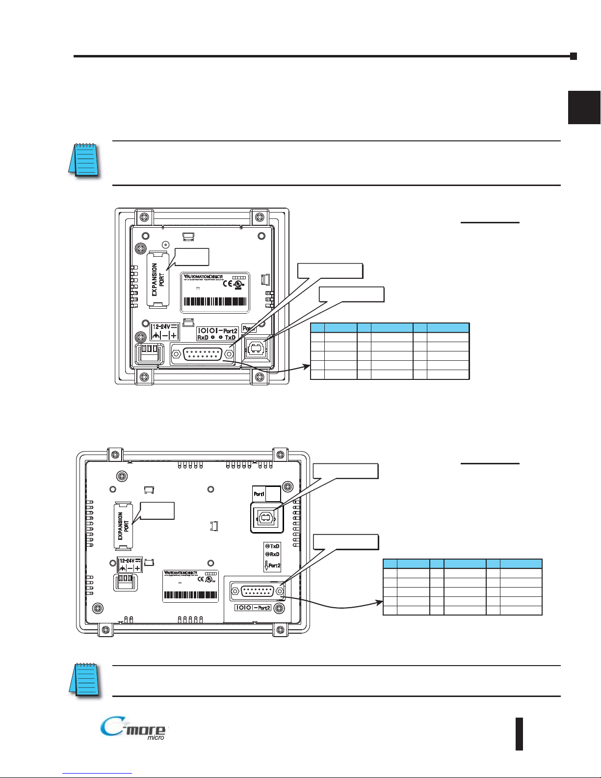
Step 3 – Become Familiar with Available Communication Ports
The C-more Color Micro-Graphic panel includes a built-in USB Type B port used to
communicate with a PC during project development. There is a 15-pin RS-232/RS-422/RS485 port for communications to a PLC.
NOTE: When the panel is powered through Port1 from a connected PC, the screen brightness is diminished
because the panel is running in Low-Power Mode. Connect an external 12-24 VDC power source when the
panel is installed in its application for full brightness.
NOTE: See Chapter 2: Specifications and Chapter 6: PLC Communications for additional details on the
available communication ports, protocols and cables.
EA1-TCL-M Hardware User Manual, 2nd Ed., 10/10
1–9
Chapter 1: Getting Started
1
®
ND.CONT.EQ.
ND.CONT.EQ.
7M17
7M17
MODEL:EA1 T4CL
MODEL:EA1 T4CL
Date code:9048
Date code:9048
MADE IN CHINA
MADE IN CHINA
NPUT:12-24V 019 0.38A
NPUT:12-24V 019 0.38A
Clas 2
Clas 2
EA1-T4CL
EA1-T4CL+
094018001
094018001
5432
1
R**.
R**.
Expansion
Connector
USB Type B
Programming Port1
PLC 15-pin serial
communications Port2
Pin Signal
1 Frame GND
TXD (232C)
RXD (232C)
Future
2
3
4
5 Logic GND
P n Signal Pin Signal
6LE
CTS (232C)
RTS (232C)
RXD+ (422/485)
7
8
9
10 RXD (422/485)
11 TXD+ (422/485)
TXD (422/485)
Term Resstor
do not use
12
13
14
15 do not use
RS-232/422/485
NPUT:12-24V 65W Class2
NPUT:12-24V 65W Class2
ISTED
ISTED
7M17
7M17
Date code:* **
Date code:* **
4 4 3 3 2 2 1 1 R01
R01
MADE IN CH NA
MADE IN CH NA
EA1-T6CL + ser al number
EA1-T6CL + ser al number
MODEL:EA1-T6CL
MODEL:EA1-T6CL
IND.CONTEQ.
IND.CONTEQ.
8 1
15
9
Pin Signal
1 Frame GND
TXD (232C)
RXD (232C)
Future
2
3
4
5 Logic GND
Pin Signal Pin Signal
6 LE
CTS (232C)
RTS (232C)
RXD+ (422/485)
7
8
9
10 RXD (422/485)
11 TXD+ (422/485)
TXD (422/485)
Term Resistor
do not use
12
13
14
15 do not use
RS-232/422/485
Expansion
Connector
USB Type B
Programming Port1
PLC 15-pin serial
communications Port2
EA1-T4CL
EA1-T6CL
Page 20
EA1-TCL-M Hardware User Manual, 2nd Ed., 10/10
1–10
Chapter 1: Getting Started
1
®
Step 4 – Install C-more Color Micro-Graphic Panel
The C-more Micro-Graphic panel can be mounted through a cutout in an enclosure by using
the template that is provided with the panel, or using the dimensions that follow. Cutout
dimensions for the C-more 6” Color Micro-Graphic panel 20-button landscape and 21-button
portrait keypad bezel options are also shown on the next page. The keypad bezels also include
a template that can be used.
The enclosure mounting thickness range for the panels and the keypad bezels is 0.04”–0.2”
[1–5 mm].
The screw torque range for the screws used on the panel mounting clips and the keypad bezel
mounting clips is 21-28 oz-in [0.15-0.2 Nm].
See Chapter 2: Specifications for additional product dimensions and Chapter 3: Accessories
for accessory specifications and dimensions.
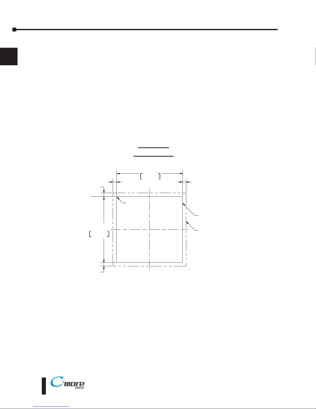
EA1-T4CL
Panel Cutout
0.344
[8.8]
0.344
[8.8]
0.344
[8.8]
0.344
[8.8]
R .079 [R2]
CUTOUT
CUTOUT
OUTLINE
BEZEL
OUTLINE
92.0
+1
0
+0 04
0 00
3.622
92.0
+1
0
+0 04
0 00
3.622
Page 21
EA1-TCL-M Hardware User Manual, 2nd Ed., 10/10
1–11
Chapter 1: Getting Started
1
®
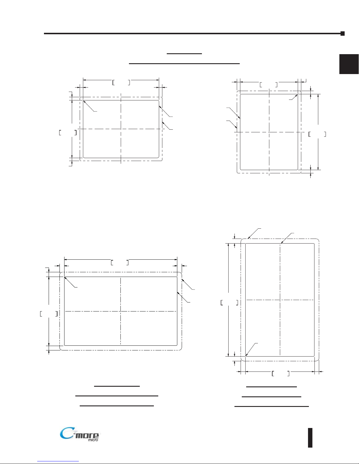
0.260
[6.6]
0.256
[6.5]
0.256
[6.5]
0.260
[6.6]
R .118 [R3]
CUTOUT
CUTOUT
OUTLINE
BEZEL
OUTLINE
122.2
+1
0
+0 04
0 00
4.811
161.0
+1
0
+0 04
0 00
6.339
0.382
[9.7]
0.382
[9.7]
0.382
[9.7]
0.382
[9.7]
143.0
+1
0
+0 04
0 00
5.630
CUTOUT
234.6
+1
0
+0 04
0 00
9.236
R0.59 [R1.5]
CUTOUT
OUTLINE
BEZEL
OUTLINE
EA1-T6CL
Panel and Accessories Cutouts
BEZEL
OUTLINE
0.382
[9.7]
0.382
[9.7]
0.382
[9.7]
0.382
[9.7]
143.0
+1
0
+0 04
0 00
5.630
CUTOUT
234.6
+1
0
+0 04
0 00
9.236
R0.59 [R1.5]
CUTOUT
OUTLINE
EA-MG6-BZ2
Landscape (Horizontal)
Keypad Bezel Cutout
EA-MG6-BZ2P
Portrait (Vertical)
Keypad Bezel Cutout
0.260
[6.6]
0.256
[6.5]
0.256
[6.5]
0.260
[6.6]
R .118 [R3]
CUTOUT
CUTOUT
OUTLINE
BEZEL
OUTLINE
122.2
+1
0
+0 04
0 00
4.811
161.0
+1
0
+0 04
0 00
6.339
Landscape Mode (Horizontal) Portrait Mode (Vertical)
Page 22
EA1-TCL-M Hardware User Manual, 2nd Ed., 10/10
1–12
Chapter 1: Getting Started
1
®
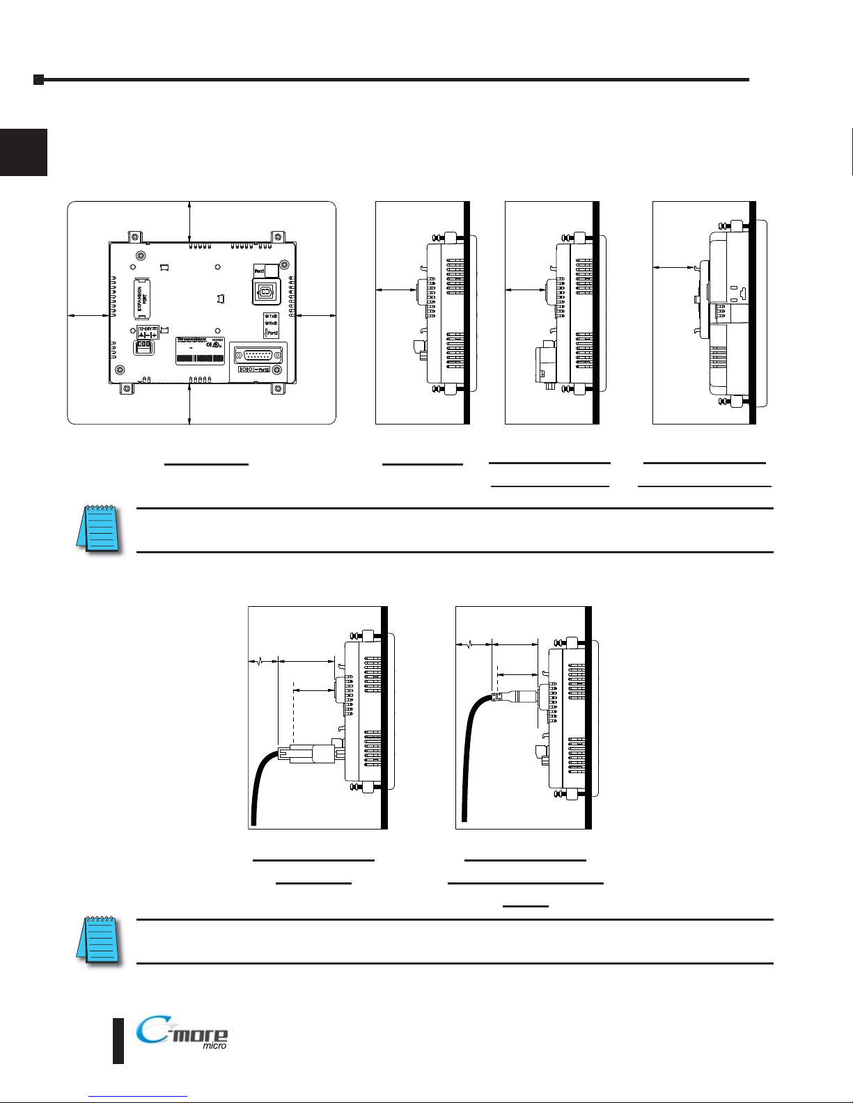
Enclosure Clearances
In all installations, a 1.2” [30mm] minimum clearance is required inside an enclosure for
proper ventilation of the C-more Micro-Graphic panel.
Enclosure Enclosure
1.2
[30.0]
1.5
[38.1]
1.2
[30.0]
2
[50.8]
*
*
* Additional clearance for cable bend radius typically 1/2” to 1”
Side View with
EA-2CBL
NOTE: Cable connectors are typically longer than 1.2” (30mm). Therefore, in addition to ventilation
requirements, clearance must account for the connector and the cable bend radius.
Enclosure
1.2
[30.0]
Enclosure
1.2
[30.0]
1.2
[30.0]
PU : 2 24V 5W Ca s2
I T D
M 7
ae c de * *
01
M DE N CH NA
A1 T CL + e i l n mber
LMOD L EA -T CL
NDCONT. Q.
81
15
9
1.2
[30.0]
Enclosure
units: inches [mm]
Enclosure
1.2
[30.0]
1.2
[30.0]
1.2
[30.0]
Rear View
EA1-T6CL with
EA-MG6-BZ2(P)
Side view
Side View with
EA-ADAPTR-4
Side View with
USB programming
cable
NOTE: Additional clearance inside the enclosure is required when connecting to the 15-pin serial
communications port (Port2) unless the 90 EA-ADPTR-4 is used.
Page 23
EA1-TCL-M Hardware User Manual, 2nd Ed., 10/10
1–13
Chapter 1: Getting Started
1
®®
Step 5 – Install the Programming Software and Develop a Project
Following are the minimum system requirements for running C-more Micro-Graphic
Programming Software, EA-MG-PGMSW, on a PC:
• Personal Computer with a 333 MHz or higher processor (CPU) clock speed recommended;
Intel® Pentium/Celeron family, or AMD® K6/Athlon/Duron family, or compatible processor
recommended
• Keyboard and Mouse or compatible pointing device
• Super VGA color video adapter and monitor with at least 800 x 600 pixels resolution
(1024 x 768 pixels recommended) 64K color minimum
• 150 MB free hard-disk space
• 128 MB free RAM (512 MB recommended)
• CD-ROM or DVD drive for installing software from the CD, or internet access to download free
programming software
• USB port to use with a programming cable, such as a USB-CBL-AB6, for transfering a project from
the programming software to the panel
• Operating System - Windows® XP Home / Professional Edition Service Pack 2, Windows® 2000
with Service Pack 4, Windows® Vista (32 and 64 bit) or Windows® 7 (32 and 64 bit)
Insert the C-more Micro-Graphic Programming Software CD-ROM into the PC’s CD-ROM
drive or download the programming software from www.automationdirect.com and follow the
instructions. If you need assistance during the software installation, please refer to the supplied
Software Installation Guide or call the AutomationDirect Technical Support team at
770-844-4200.
NOTE: The panel has an internal USB to serial converter at Port1. When the device is properly installed and
the USB programming cable connects the panel to the PLC, the port will be identified as a serial
communications port with an assigned COM port number.
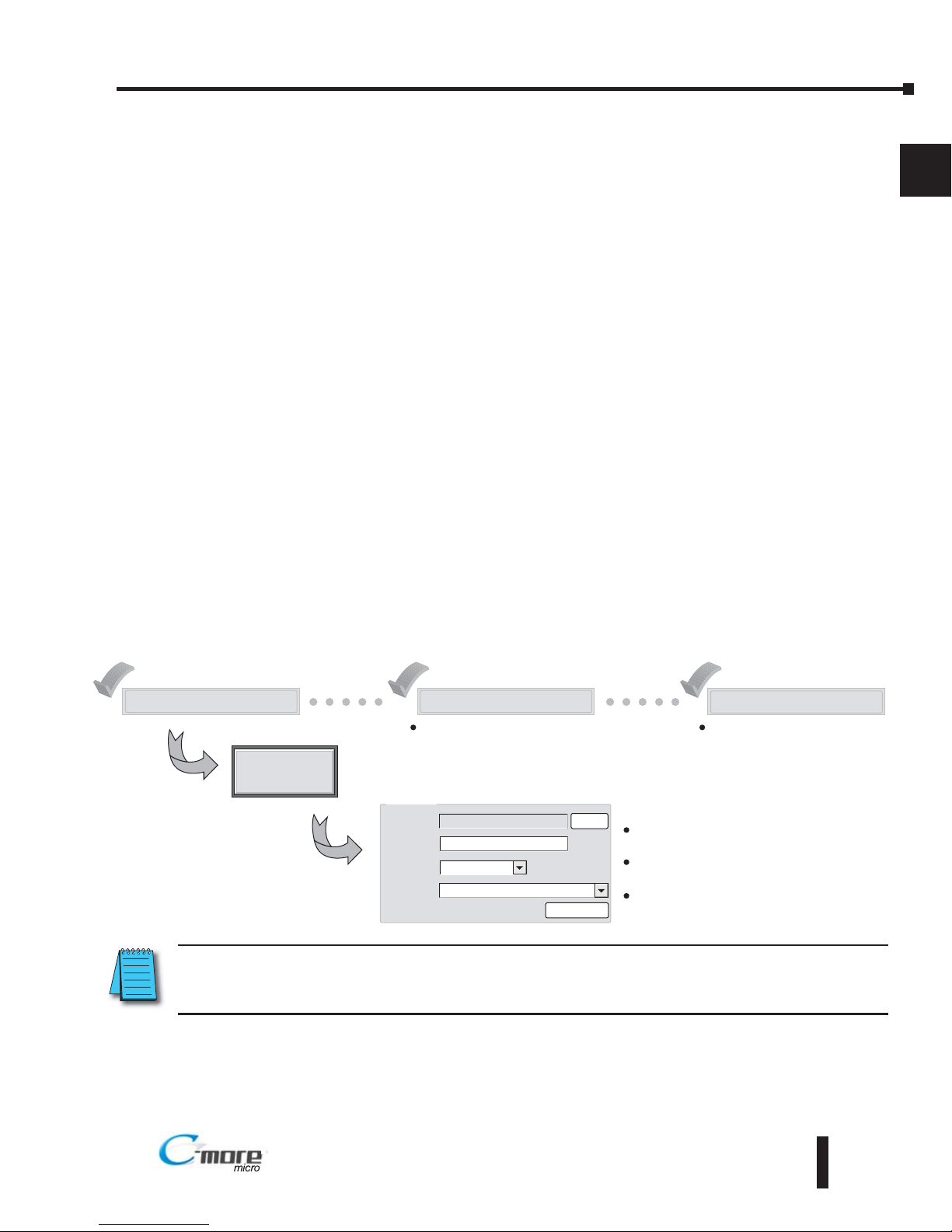
Start a Project
Simulate Project
Send Project to panel
Allows you to check the operation of
your project before downloading it to
the panel.
Download your project to the
connected panel.
Enter a name
for your project
Make a New Project
PLC Protocol
DirectLogic K Sequence
HMI Type
Project
Location
EA1 T6CL
MyProject
C \My Documents\C more Projects\
Select Project
Protocol Setup
Browse
Select the C-more
Micro-Graphic panel
Select the PLC Driver
Page 24
EA1-TCL-M Hardware User Manual, 2nd Ed., 10/10
1–14
Chapter 1: Getting Started
1
®®
1–14
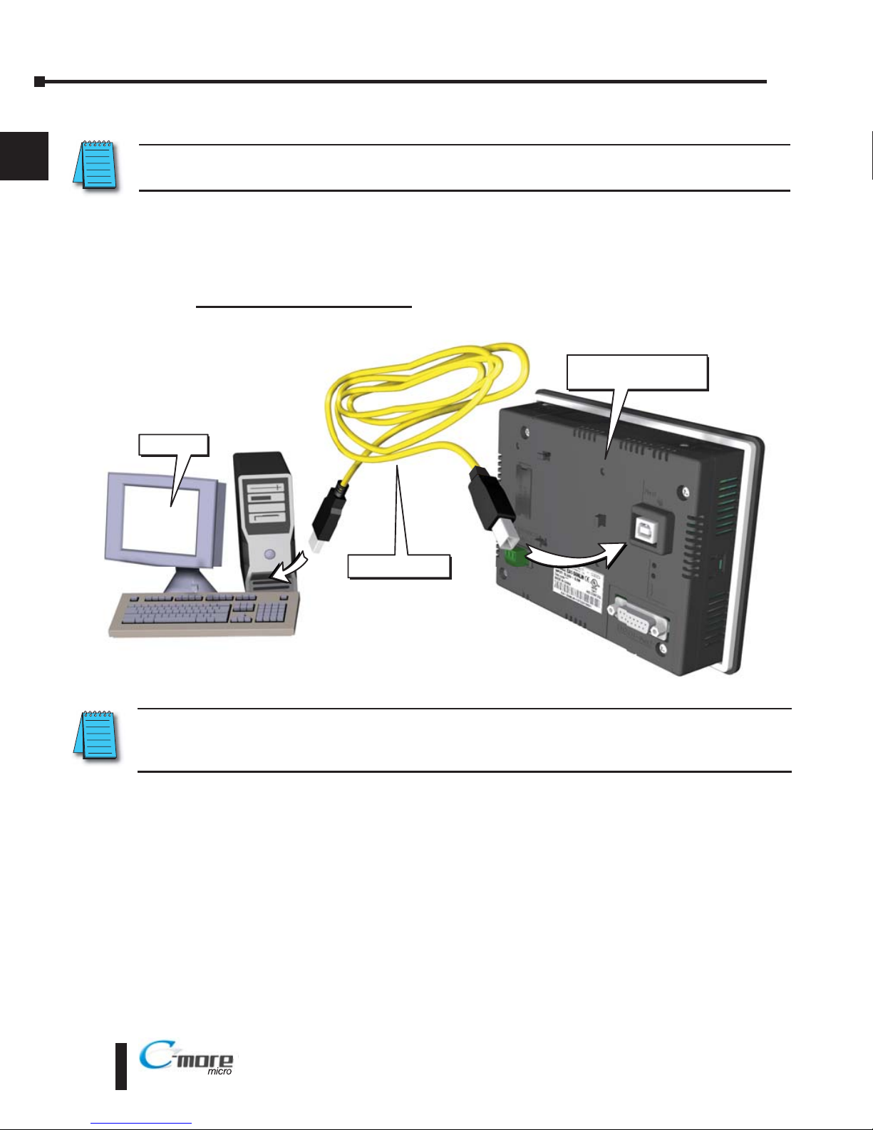
Step 6 – Connect C-more Color Micro-Graphic Panel to Computer
NOTE: Install C-more Micro-Graphic Programming software before connecting the panel to the PC to ensure
the panel drivers install correctly.
Use a programming cable such as USB-CBL-AB6 from a USB port type A on the project
development PC to the USB port type B on the C-more Color Micro Graphic Panel as shown
below. Any standard Type A to Type B USB cable can be used such as a standard USB printer
cable, maximum length 15’.
User PC
USB CBL AB6
C-more Color
Micro Graphic Panel
USB Programming Cable
NOTE: When the panel is powered through Port1 from a connected PC, the screen brightness is diminished
because the panel is running in Low-Power Mode. Connect an external 12-24 VDC power source when the
panel is installed in its application for full brightness.
Page 25
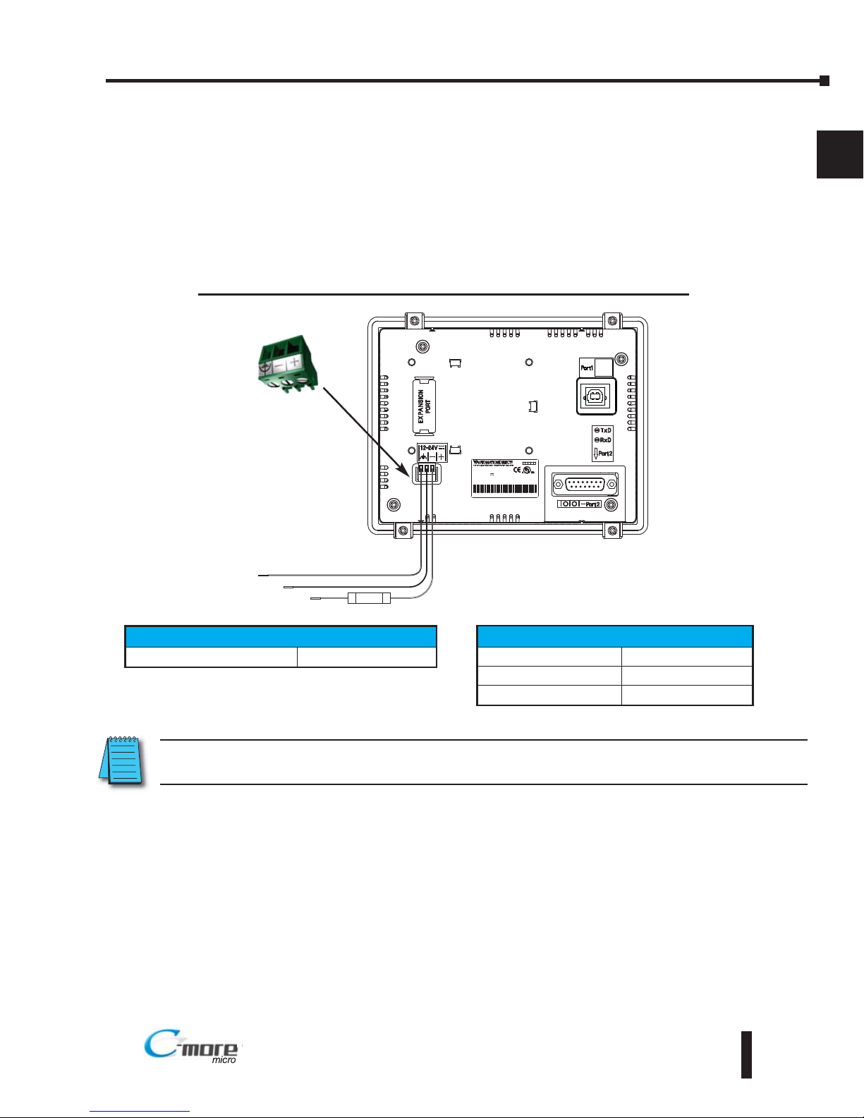
Step 7 – Providing Power to the C-more Color Micro-Graphic Panel
Power can be supplied to the C-more Micro-Graphic panel in one of three different ways.
1). The panel is powered by a 1 Amp @ 12-24 VDC power source in normal operation.
2). The C-more Micro-Graphic panel can be powered during programming from the PC through a
USB Programming Cable such as USB-CBL-AB6. When powered from the PC, the panel will
operate in Low-Power mode and the screen brightness is diminished.
EA1-TCL-M Hardware User Manual, 2nd Ed., 10/10
1–15
Chapter 1: Getting Started
1
®®
INPUT12 24V 6 5W Cla s2
INPUT12 24V 6 5W Cla s2
ST D
ST D
7M17
7M17
Da e code:* **
Da e code:* **
53
1
R01
R01
MADE N CHINA
MADE N CHINA
EA1- 6C + er al number
EA1- 6CL + er al number
MODEL EA1-T6CL
MODEL EA1-T6CL
ND.CONTEQ.
ND.CONTEQ.
81
15
9
Supply to Panel:
1 A @ 12 - 24 VDC
(10.8 - 26.4 VDC)
+
–
GND
Equipment
Ground
Recommended
DC Supply Fuse
750 mA fast acting,
ADC p/n AGC-75
Panel Powered from a DC Power Source - Wiring Diagram
NOTE: Recommended DC power supply to power the C-more Micro Graphic Panel, AutomationDirect Part No.
PSP24-024S or PSP24-024C.
Tightening Torque
Power supply wire connection 1 7 lb-in (0.2 Nm)
Required Wire Specification
Supported temperature Over 60 °C
Wire Material Copper
Wire Size 16 - 22 AWG
Page 26
EA1-TCL-M Hardware User Manual, 2nd Ed., 10/10
1–16
Chapter 1: Getting Started
1
®®
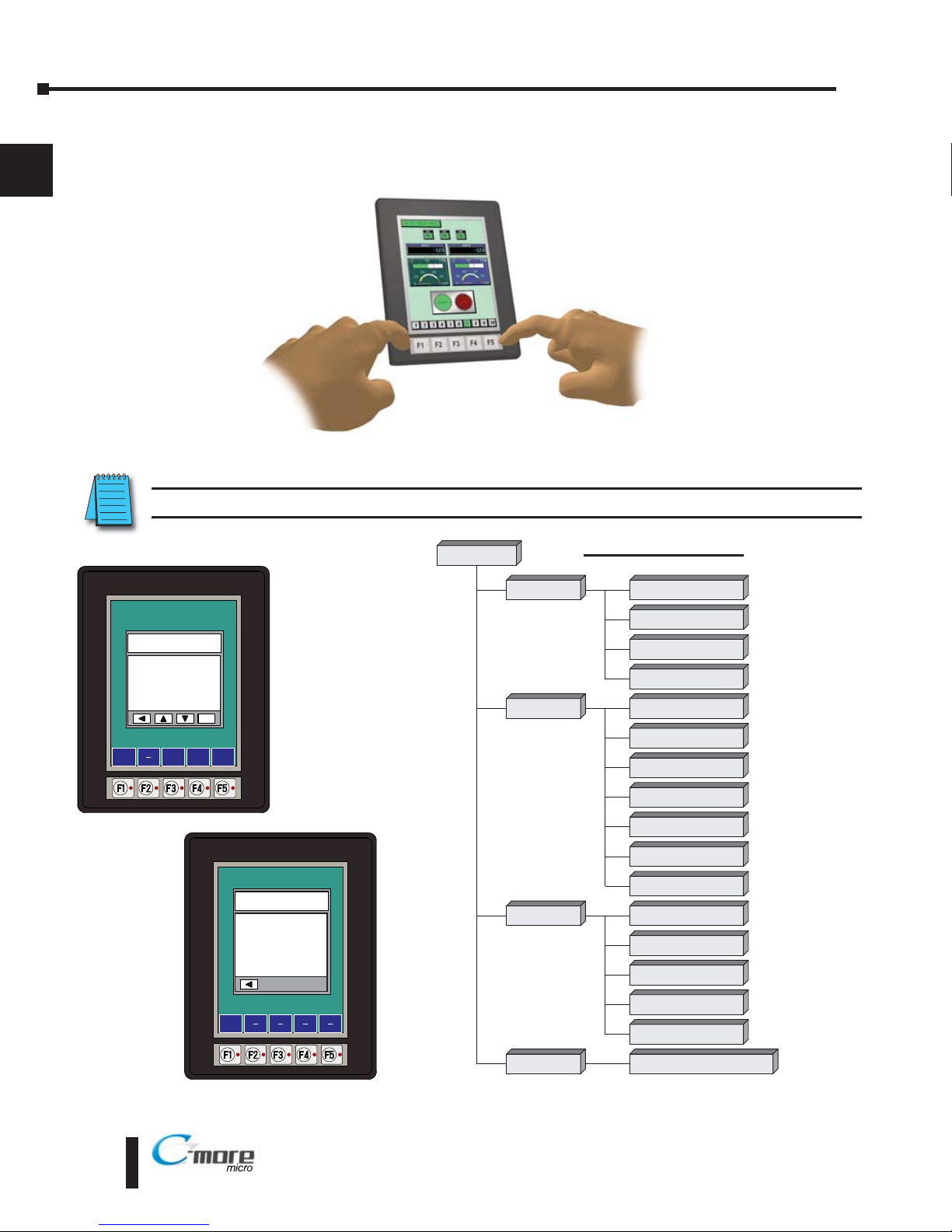
Step 8 – Accessing the C-more Color Micro-Graphic Panel Setup Screens
To access the Setup Menu of the panel’s setup screens, press the the BAK [F1] and ENT [F5]
function keys simultaneously for three (3) seconds.
From the Setup Menu, information about the panel can be obtained, settings can be adjusted,
and panel functions can be tested.
NOTE: See Chapter 5: System Setup Screens for details on using the setup screen settings and functions.
Setup Menu
[pg 5 5]
1 Information
[pg 5 6]
1 Memory
[pg 5 6]
2 Setting
[pg 5 7]
1 Brightness
[pg 5 7]
2 Touch / Key Beep
[pg 5 8]
4 Calibration
[pg 5 9]
5 Clear User Memory
[pg 5 10]
1 Serial Port Loop Back Test
[pg 5 14]
2 PLC Enquiry Test
[pg 5 15]
Do you want to exit from System Screen?
No[F1] / Yes[F5]
3 Test Menu
[pg 5 13]
4 Exit
[pg 5 17]
2 Protocol
[pg 5 6]
3 Extens ons
[pg 5 6]
4 Versions
[pg 5 6]
6 Reset to Factory Default
[pg 5 10]
7 Hourglass
[pg 5 11]
8 Rotation
[pg 5 12]
3 Buzzer Test
[pg 5 15]
4 Touch Panel Test
[pg 5 16]
5 Display Test
[pg 5 16]
Menu Flow Chart
BAK
UP
DWN ENT
1 Information >
2 Setting >
3 Test Menu >
4 Exit >
ENT
SETUP MENU
BAK
Total
3276800 Bytes
Usage
0 Bytes
Free
3276800 Bytes
MEMORY
Page 27
EA1-TCL-M Hardware User Manual, 2nd Ed., 10/10
1–17
Chapter 1: Getting Started
1
®
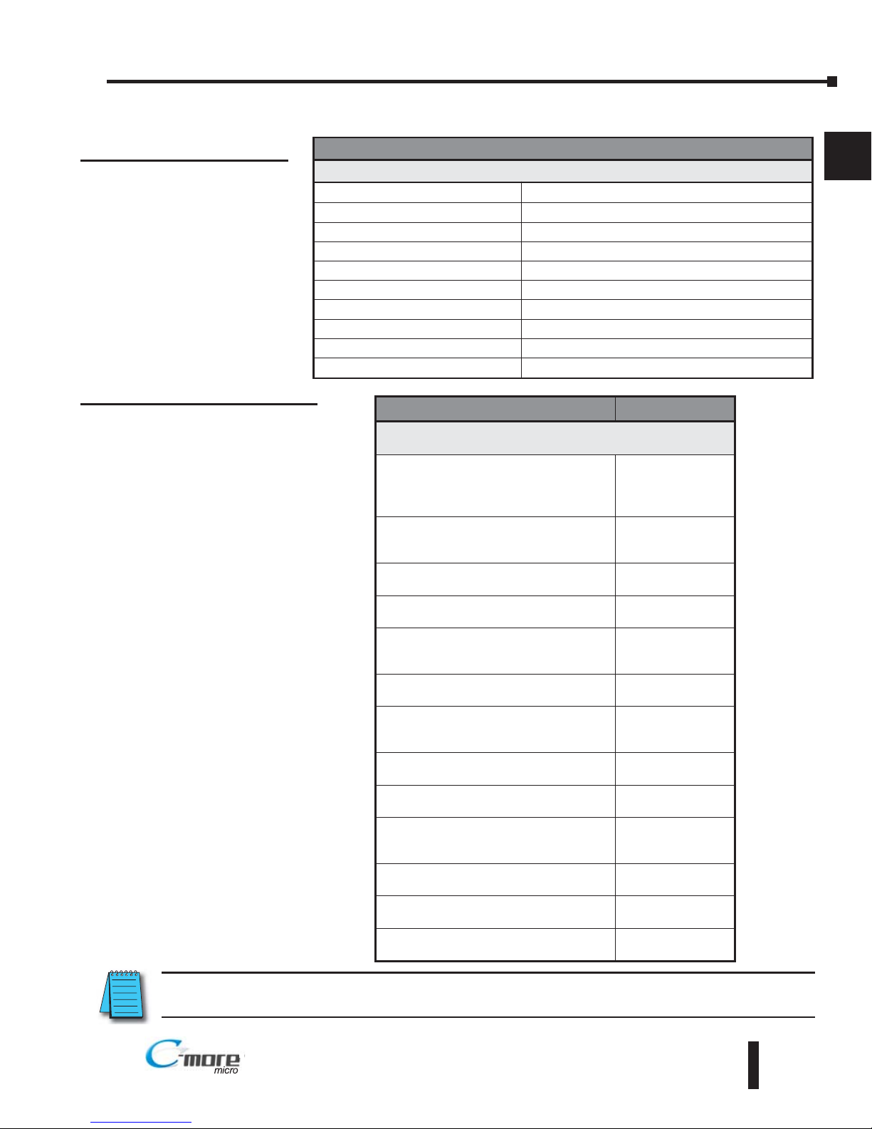
Step 9 – Choose C-more Color Micro-Graphic Panel to PLC Protocol & Cables
®
NOTE: See Chapter 6: PLC Communications for a detailed chart of PLC compatibility & cable connections.
Chapter 6 includes wiring diagrams for end user construction of certain cables.
Available purchased cables
Cable Description Cable Part No.
Cables used with serial Port2
AutomationDirect Productivity Series,
CLICK,
Direct
LOGIC PLC RJ-12 port,
DL05, DL06, DL105, DL205, D3-350, D4450 & H2-WinPLC (RS-232C)
EA-2CBL
Direct
LOGIC (VGA Style) 15-pin port,
DL06, D2-250 (250-1), D2-260
(RS-232C).
EA-2CBL-1
Direct
LOGIC PLC RJ-11 port, D3-340
(RS-232C).
EA-3CBL
Direct
LOGIC DL405 PLC 15-pin D-sub
port, DL405 (RS-232C).
EA-4CBL-1
Direct
LOGIC PLC 25-pin D-sub port,
DL405, D3-350, DL305 DCU and all DCM’s
(RS-232C).
EA-4CBL-2
Allen-Bradley MicroLogix 1000, 1100,
1200 & 1500 (RS-232C)
EA-MLOGIX-CBL
Allen-Bradley SLC 5-03/04/05,
ControlLogix, CompactLogix, FlexLogix
DF1 port (RS-232C)
EA-SLC-232-CBL
Allen-Bradley PLC-5 DF1 port
(RS-232C)
EA-PLC5-232-CBL
Allen-Bradley MicroLogix, SLC 5-01/02/03,
PLC5 DH485 port (RS-232C)
EA-DH485-CBL
GE 90/30, 90/70, Micro 90, Versamax
Micro (Port2) 15-pin D-sub port
(RS-422A)
EA-90-30-CBL
MITSUBISHI FX Series 25-pin port
(RS-422A)
EA-MITSU-CBL
MITSUBISHI FX Series 8-pin mini-DIN
(RS-422A)
EA-MITSU-CBL-1
OMRON Host Link (C200 Adapter, C500)
(RS-232C)
EA-OMRON-CBL
PLC Drivers
Serial - port2 only
AutomationDirect Productivity Series Allen-Bradley DF1 Full Duplex
AutomationDirect CLICK Allen-Bradley PLC5 DF1
AutomationDirect K-sequence Allen-Bradley DH485
AutomationDirect DirectNET GE SNPX (90/30, 90/70, Micro 90, VersaMax Micro)
AutomationDirect Modbus Mitsubishi FX
AutomationDirect SOLO Mitsubishi (Q, QnA)
AutomationDirect GS Drives Omron Host Link (C200 Adapter, C500)
Modicon Modbus RTU Omron FINS Serial (CJ1, CS1)
Entivity Modbus RTU Siemens PPI (S7-200 CPU)
Allen-Bradley DF1 Half Duplex
Available PLC Protocols
Page 28
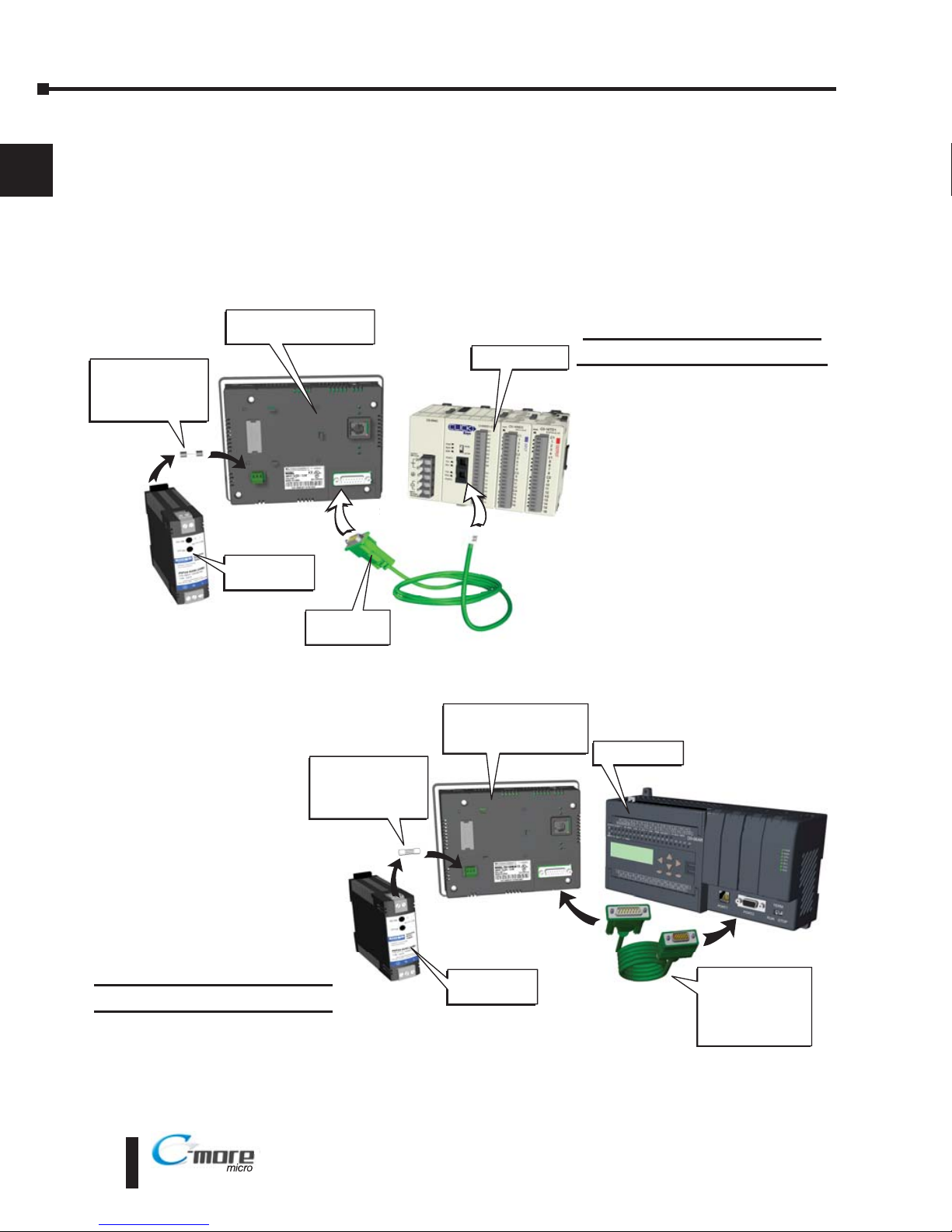
Step 10 – Connect C-more Color Micro-Graphic Panel to PLC
Connect the serial communications cable between the C-more Micro-Graphic panel and the
PLC. The panel can be connected to the PLC via the panel’s built-in 15-pin serial
communications port with either RS-232, RS-422 or RS-485 communications.
®
Port 2
Port
2
PSP-24-024S
Power Supply
Recommended
DC Supply Fuse
750 mA fast acting,
ADC p/n AGC-75
EA 2CBL
serial cable
C-more Color
Micro-Graphic Panel
CLICK PLC
Port
2
Port
2
C-more to
Direct LOGIC
VGA 15 pin port
serial cable
p/n EA 2CBL 1
DL-06 PLC
PSP-24-024S
Power Supply
Recommended
DC Supply Fuse
750 mA fast acting,
ADC p/n AGC-75
C-more Color
Micro-Graphic
Panel
Example of panel’s Port 2
connected to a CLICK PLC
Example of panel’s Port 2
connected to a DL06 PLC
®
1
Chapter 1: Getting Started
1–18
EA1-TCL-M Hardware User Manual, 2nd Ed., 10/10
Page 29

SPECIFICATIONS
CH
CHAPTER
2
2
CHAPTER
In This Chapter...
Available Models . . . . . . . . . . . . . . . . . . . . . . . . . . . . . . . . . . . . . . . . . . . . . . . . . . . .2–2
EA1-T4CL Specifications . . . . . . . . . . . . . . . . . . . . . . . . . . . . . . . . . . . . . . . . . . . . . .2–3
EA1-T6CL Specifications . . . . . . . . . . . . . . . . . . . . . . . . . . . . . . . . . . . . . . . . . . . . . .2–5
EA1-T4CL Panel Dimensions . . . . . . . . . . . . . . . . . . . . . . . . . . . . . . . . . . . . . . . . . . .2–7
EA1-T6CL Panel Dimensions . . . . . . . . . . . . . . . . . . . . . . . . . . . . . . . . . . . . . . . . . . .2–8
Communications Port . . . . . . . . . . . . . . . . . . . . . . . . . . . . . . . . . . . . . . . . . . . . . . . .2–9
Chemical Compatibility . . . . . . . . . . . . . . . . . . . . . . . . . . . . . . . . . . . . . . . . . . . . . .2–10
Page 30

2–2
Chapter 2: Specifications
2
®
EA1-TCL-M Hardware User Manual, 2nd Ed., 10/10
Available Models
The C-more Color Micro-Graphic panels expand the next generation of HMI panels brought
to you by AutomationDirect. They have been designed to display and interchange graphical
data from a PLC by viewing, using the function keys, or touching the screen. See Chapter 3:
Accessories for details on the available accessories for the C-more Color Micro-Graphic panels.
C-more
Color Micro-Graphic Panels
Part Number Description
EA1-T4CL
4-inch
C-more
Micro-Graphic Touch Panel with TFT Color LCD, 320 x 240
dot, 32,768 color display with LED backlight. 5 user-defined function keys
with LED indicators. Two built-in ports (USB Type-B port and 15-pin Dsub RS-232/422/485 port). Display supports portrait and landscape
modes. NEMA 4/4X, IP65 (when mounted correctly; for indoor use only)
EA1-T6CL
6-inch
C-more
Micro-Graphic Touch Panel with TFT Color LCD, 320 x 240
dot, 32,768 color display with LED backlight. 5 user-defined function keys
with LED indicators. Two built-in ports (USB Type-B port and 15-pin Dsub RS-232/422/485 port). Display supports portrait and landscape
modes. NEMA 4/4X, IP65 (when mounted correctly; for indoor use only)
C-more 6” Color
Micro-Graphic Panel
C-more 6” Color Micro-Graphic Panels Installed in
Landscape and Portrait Keypad Bezels
Page 31

EA1-T4CL Specifications
Specification table continued at the top of the next page.
2–3
Chapter 2: Specifications
2
EA1-TCL-M Hardware User Manual, 2nd Ed., 10/10
®
Specifications
Description:
320 x 240 dots LCD display (Landscape Mode),
Five user defined keypad function buttons, and five user defined LED's
Display:
• Type
4.1" TFT Color LCD, graphical characters
• Resolution
320 (W) x 240 (H) dots (Landscape Mode)
240 (W) x 320 (H) dots (Portrait Mode)
• Color
32768 colors
• Display Brightness
(Reference)
USB Bus Power (Programming) High Power Mode
180 nits (typ) 360 nits (typ)
• Viewing Area Size
3.357” (W) x 2.54” (H) [85.26 mm x 64.62 mm]
• Active Area Size
3.250” (W) x 2.438” (H) [82.56 mm x 61.92 mm]
• Brightness
Adjusted from the panel’s built-in configuration setup menu
• Viewing Angle
(landscape mode)
3, 9 o’clock axis –> 35 degrees
6 o’clock axis –> 50 degrees
12 o’clock axis –> 20 degrees
Backlight:
• Type
LED
• Color
White
• User Replaceable
No
Touch Screen:
•Type
Analog touch panel
• Operation
82 gram force [0.8 N] maximum
• Life
Minimum of 1,000,000 cycles
Features:
• User Memory
3276 kBytes
• Number of Screens
Up to 999 – limited by project memory usage
• Beep (Internal)
Yes
• Keypad Function Buttons
Five user defined function key buttons with the ability to custom label with an overlay.
Minimum of 500,000 cycles
• Keypad Function Button
LEDs
Each function key button includes a red LED that can be user programmed.
• Programming Port
USB Type B (USB 2.0 full speed mode 12 Mbps)
• Serial Communications
15-pin D-sub serial communications port (RS-232, RS-485 / 422).
Page 32

EA1-T4CL Specifications (cont’d)
2–4
Chapter 2: Specifications
2
®
EA1-TCL-M Hardware User Manual, 2nd Ed., 10/10
Specifications (cont’d)
Screen Objects:
• Functional Devices
Push Button, Switch, Indicator Button, Indicator Light, Graphic Indicator Light, Numeric
Display, Numeric Entry, Inc/Dec Value, Bar Graph, Bitmap Button, Static Bitmap, Dynamic
Bitmap, Multi-State Bitmap, Recipe Button, Radio Button, Tri-State Button Static Text,
Lookup Text, Dynamic Text, Scroll Text, Screen Change Push Button, Screen Selector, Adjust
Contrast, Function Key Configuration Object, Real Time Graphics Line Graph, Analog Meter.
• Static Shapes
Lines, Rectangles, Circles and Frames
• Displayable Fonts
Fixed fonts: 4x6, 6x6, 6x6B, 6x8, 8x16, 8x32, 8x64, 16x16, 16x32, 16x64,
32x16, 32x32, 32x64, and Windows fonts
Electrical:
USB Bus Power (Programming) High Power Mode
• Input Voltage Range
5.0 VDC (4.75 – 5.25 VDC) 12/24 VDC (10.2 – 26.4 VDC)
• Input Power
Supplied from a PC USB.
Supplied from an external
12-24 VDC power source
• Power Consumption
2W 4.5 W
• Recommended Fuse
No fuse required when directly connected to
a PC with recommended cable.
Type AGC fast acting glass fuse,
750 mA, 250 VAC, ADC p/n AGC-75
• Max.Inrush Current
4.5 A for 800 µs 8 A for 800 µs
• Acceptable External
Power Drop Duration
Maximum 1 ms
Environmental:
• Operating Temperature
0 to 50 °C (32 to 122 °F)
Maximum surrounding air temperature rating: 50 °C
• Storage Temperature
–20 to +60 °C (–4 to +140 °F)
• Humidity
5–95% RH (non-condensing)
• Environmental Air
For use in Pollution Degree 2 environment
• Vibration
IEC60068-2-6 (Test Fc), 5-9 Hz: 3.5 mm amplitude, 9-150 Hz: 1.0G, sweeping, at a rate of
1 octave/min. (±10%), 10 sweep cycles per axis on each of 3 mutually perpendicular axes
• Shock
IEC60068-2-27 (Test Ea), 15 G peak, 11 ms duration, three shocks in each direction per
axis, on 3 mutually perpendicular axes (total of 18 shocks)
• Noise Immunity
NEMA ICS3-304
RFI, (145 MHz, 440 Mhz 10 W @ 10 cm)
Impulse 1000 V @ 1 µs pulse
• Enclosure
For use on a flat surface of Type 1, 4X enclosure (Indoor use only)
• Agency Approvals
CE (EN61131-2), UL508, CUL Canadian C22.2 No. 142-M95, UL File E157382
Physical:
• Dimensions
4.311” (W) x 4.362” (H) x 2.035” (D) [109.5 mm x 110.8 mm x 51 7 mm] (Landscape Mode)
4.362” (W) x 4.311” (H) x 2.035” (D) [109.5 mm x 110.8 mm x 51 7 mm] (Portrait Mode)
• Enclosure Mounting
Thickness Range
0.04” – 0.2” [1 – 5 mm]
• Mounting Clip Screw
Torque Range
21 – 28 oz-in [0.15 – 0.2 Nm]
• Weight
14.99 oz. (425 g)
Page 33

EA1-T6CL Specifications
Specification table continued at the top of the next page.
2–5
Chapter 2: Specifications
2
EA1-TCL-M Hardware User Manual, 2nd Ed., 10/10
®®
Specifications
Description:
320 x 240 dots LCD display (Landscape Mode),
Five user defined keypad function buttons, and five user defined LED's
Display:
• Type
5.7" TFT Color LCD, graphical characters
• Resolution
320 (W) x 240 (H) dots (Landscape Mode)
240 (W) x 320 (H) dots (Portrait Mode)
• Color
32768 colors
• Display Brightness
(Reference)
USB Bus Power (Programming) High Power Mode
45 nits (typ) 270 nits (typ)
• Viewing Area Size
4.574” (W) x 3.483” (H) [116.2 mm x 87.4 mm]
• Active Area Size
4.535” (W) x 3.400” (H) [115.2 mm x 86.4 mm]
• Brightness
Adjusted from the panel’s built-in configuration setup menu
• Viewing Angle
(landscape mode)
3, 9 o’clock axis –> 50 degrees
6 o’clock axis –> 50 degrees
12 o’clock axis –> 45 degrees
Backlight:
• Type
LED
• Color
White
• User Replaceable
No
Touch Screen:
•Type
Analog touch panel
• Operation
82 gram force [0.8 N] maximum
• Life
Minimum of 1,000,000 cycles
Features:
• User Memory
3276 kBytes
• Number of Screens
Up to 999 – limited by project memory usage
• Beep (Internal)
Yes
• Keypad Function Buttons
Five user defined function key buttons with the ability to custom label with an overlay.
Minimum of 500,000 cycles
• Keypad Function Button
LEDs
Each function key button includes a red LED that can be user programmed.
• Programming Port
USB Type B (USB 2.0 full speed mode 12 Mbps)
• Serial Communications
15-pin D-sub serial communications port (RS-232, RS-485 / 422).
• Expansion Connection
Yes – used with optional Keypad Bezels, EA-MG6-BZ2 & EA-MG6-BZ2P
Page 34

2–6
Chapter 2: Specifications
2
®
EA1-TCL-M Hardware User Manual, 2nd Ed., 10/10
®
EA1-T6CL Specifications (cont’d)
Specifications (cont’d)
Screen Objects:
• Functional Devices
Push Button, Switch, Indicator Button, Indicator Light, Graphic Indicator Light, Numeric
Display, Numeric Entry, Inc/Dec Value, Bar Graph, Bitmap Button, Static Bitmap, Dynamic
Bitmap, Recipe Button, Static Text, Lookup Text, Dynamic Text, Screen Change Push Button,
Screen Selector, Adjust Contrast, Function, Key Configuration Object, Real Time Graphics
Line Graph, Analog Meter.
• Static Shapes
Lines, Rectangles, Circles and Frames
• Displayable Fonts
Fixed fonts: 4x6, 6x6, 6x6B, 6x8, 8x16, 8x32, 8x64, 16x16, 16x32, 16x64,
32x16, 32x32, 32x64, and Windows fonts
Electrical:
USB Bus Power (Programming) High Power Mode
• Input Voltage Range
5.0 VDC (4.75 – 5.25 VDC) 12/24 VDC (10.2 – 26.4 VDC)
• Input Power
Supplied from a PC USB.
Supplied from an external
12-24 VDC power source
• Power Consumption
2W 6.5 W
• Recommended Fuse
No fuse required when directly connected to
a PC with recommended cable.
Type AGC fast acting glass fuse,
750 mA, 250 VAC, ADC p/n AGC-75
• Max.Inrush Current
4.5 A for 800 µs 13 A for 800 µs
• Acceptable External
Power Drop Duration
Maximum 1 ms
Environmental:
• Operating Temperature
0 to 50 °C (32 to 122 °F)
Maximum surrounding air temperature rating: 50 °C
• Storage Temperature
–20 to +60 °C (–4 to +140 °F)
• Humidity
5–95% RH (non-condensing)
• Environmental Air
For use in Pollution Degree 2 environment
• Vibration
IEC60068-2-6 (Test Fc), 5-9 Hz: 3.5 mm amplitude, 9-150 Hz: 1.0G, sweeping, at a rate of
1 octave/min. (±10%), 10 sweep cycles per axis on each of 3 mutually perpendicular axes
• Shock
IEC60068-2-27 (Test Ea), 15 G peak, 11 ms duration, three shocks in each direction per
axis, on 3 mutually perpendicular axes (total of 18 shocks)
• Noise Immunity
NEMA ICS3-304
RFI, (145 MHz, 440 Mhz 10 W @ 10 cm)
Impulse 1000 V @ 1 µs pulse
• Enclosure
For use on a flat surface of Type 1, 4X enclosure (Indoor use only)
• Agency Approvals
CE (EN61131-2), UL508, CUL Canadian C22.2 No. 142-M95, UL File E157382
Physical:
• Dimensions
6.850” (W) x 5.331” (H) x 2.130” (D) [174.0 mm x 135.4 mm x 54.1 mm] (Landscape Mode)
5.331” (W) x 6.850” (H) x 2.130” (D) [135.4 mm x 174.0 mm x 54.1 mm] (Portrait Mode)
• Enclosure Mounting
Thickness Range
0.04” – 0.2” [1 – 5 mm]
• Mounting Clip Screw
Torque Range
21 – 28 oz-in [0.15 – 0.2 Nm]
• Weight
29.63 oz. (840 g)
Page 35

EA1-T4CL Panel Dimensions
2–7
Chapter 2: Specifications
2
EA1-TCL-M Hardware User Manual, 2nd Ed., 10/10
®
Panel Dimensions
Units: Inches [mm]
Enclosure Thickness Mounting Clip Screw Torque
.34
[8.7]
1.25
[31.8]
1.81
[45.9]
2.04
[51.7]
GASKET
MOUNTING CLIP
(4) places
4.31
[109.5]
3.58
[91.0]
4.36
[110.8]
3.58
[91.0]
NDCONT.EQ.
7M17
MODEL EA1-T4CL
Da e code 9048
MADE IN CHINA
INPUT:12 24V 0 19 0 38A Cla s2
EA1 T4CL+094018001
531R**.
MOUNTING CLIP
SCREW TORQUE RANGE
21 - 28 oz-in [0.15-0.2 Nm]
ENCLOSURE MOUNTING
THICKNESS RANGE
0.04” - 0.2” [1 - 5mm]
Page 36

EA1-T6CL Panel Dimensions
2–8
Chapter 2: Specifications
2
®
EA1-TCL-M Hardware User Manual, 2nd Ed., 10/10
6.295
[159.9]
6.850
[174.0]
.236
[6.0]
1.453
[36.9]
1.689
[42.9]
2.13
[54.1]
GASKET
MOUNTING CLIP
(4) places
Units: Inches [mm]
4.770
[121.3]
5.331
[135.4]
ENCLOSURE MOUNTING
THICKNESS RANGE
0.04” - 0.2” [1 - 5mm]
MOUNTING CLIP
SCREW TORQUE RANGE
21 - 28 oz-in [0.15-0.2 Nm]
Enclosure Thickness Mounting Clip Screw Torque
Panel Dimensions
Units: Inches [mm]
Page 37

2–9
Chapter 2: Specifications
2
EA1-TCL-M Hardware User Manual, 2nd Ed., 10/10
®
Communications Port
Expansion
Connector
ND.CONT.EQ.ND.CONT.EQ.
7M177M17
MODEL EA1 T4CLMODEL EA1 T4CL
Date code:9048Date code:9048
MADE N CHINAMADE N CHINA
NPUT: 2-24V 0 19 0 38ANPUT: 2-24V 0 19 0 38A C a s2C a s2
EA1-T4CLEA1-T4CL+094018001094018001
54321R**.R**.
Pin Signal
1 Frame GND
TXD (232C)
RXD (232C)
Future
2
3
4
5 Logic GND
Pin Signal Pin Signal
6LE
CTS (232C)
RTS (232C)
RXD+ (422/485)
7
8
9
10 RXD (422/485)
11 TXD+ (422/485)
TXD (422/485)
Term Resistor
do not use
12
13
14
15 do not use
PLC 15-pin serial
communications Port2
RS-232/422/485
USB Type B
Programming Port1
INPUT:12-24V 6.5W C ass2
INPUT:12-24V 6.5W C ass2
ISTED
ISTED
7M17
7M17
Date code:****
Date code:****
5432
1
R01
R01
MADE IN CHINA
MADE IN CHINA
EA1-T6CL + ser al number
EA1-T6CL + ser al number
MODEL:EA1-T6CL
MODEL:EA1-T6CL
IND.CONTEQ.
IND.CONTEQ.
81
15
9
Expansion
Connector
USB Type B
Programming Port1
Pin Signal
1 Frame GND
TXD (232C)
RXD (232C)
Future
2
3
4
5 Logic GND
Pin Signal Pin Signal
6LE
CTS (232C)
RTS (232C)
RXD+ (422/485)
7
8
9
10 RXD (422/485)
11 TXD+ (422/485)
TXD (422/485)
Term Resistor
do not use
12
13
14
15 do not use
PLC 15-pin serial
communications Port2
RS-232/422/485
EA1-T6CL
EA1-T4CL
Page 38

Chemical Compatibility
The C-more Micro-Graphic panels are built of three different materials that may be exposed to
elements outside of the enclosure. The panel’s screen has a polyester (PET) surface. The bezel
uses ABS plastic materials and the panel’s gasket is a silicone rubber material. The following
tables are provided to make you aware of the general compatibility between chemicals that may
be present in your work environment and the various materials used in the manufacture of the
panel. Use the table to determine those chemicals that are safe to use around your C-more
Micro-Graphic panel and those that may harm it. The tables are made up of specifications
provided by the manufacturer of the listed material. The tables rate these chemicals as either
Excellent, Good, Not Recommended, or Not Usable. Because the ratings are for ideal
conditions at room temperature, consider all factors when evaluating your application. Areas left
blank have not been tested by the manufacturer of the materials and therefore information of
compatibility is not available.
Table continued at top of next page.
2–10
Chapter 2: Specifications
2
®
EA1-TCL-M Hardware User Manual, 2nd Ed., 10/10
Chemicals
Screen Sheet – PC
[Density %,
Temperature °C]
Bezel – ABS
[Density %,
Temperature °C]
Gasket – Silicone
[Density %,
Temperature °C]
Bezel Key Sheet –
PET
[Density %,
Temperature °C]
Acetaldehyde
Not Recommended
Acetic Acid
[10, 20 °C] Excellent
[10, 20 °C] Excellent
[50, 20 °C] Not Usable
[50-70, 20 °C] Not Usable
[100, 20 °C] Not Usable
Acetic anhydride
Not Recommended
Acetone
Not Usable Not Usable Excellent
Acetophenone
Not Usable
Acetylene
Excellent
Acrylonitrile
Not Recommended
Alcohol - Butyl Ether
Excellent
Alcohol - Ethanol
Excellent
Alcohol - Isopropyl
Excellent
Alums NH3, Cr, K
Excellent
Aluminum acetate
Excellent
Aluminum bromide
Good
Aluminum chloride
Good
Aluminum nitrate
Excellent
Aluminum sulfate
Excellent
Ammonia [anhydrous]
Good
Ammonia gas [cold]
Good
Page 39

2–11
Chapter 2: Specifications
2
EA1-TCL-M Hardware User Manual, 2nd Ed., 10/10
®
Chemical Compatibility (cont’d)
Table continued at top of next page.
Chemicals
Screen Sheet – PC
[Density %,
Temperature °C]
Bezel – ABS
[Density %,
Temperature °C]
Gasket – Silicone
[Density %,
Temperature °C]
Bezel Key Sheet –
PET
[Density %,
Temperature °C]
Ammonia liquid
Good
Ammonia water
[12%] Not Usable
[28%] Not Usable
Ammonium carbonate
Excellent
Ammonium chloride
Excellent
Ammonium hydroxide
[ammonia water]
Excellent
Ammonium nitrate
Excellent
Ammonium persulfate
Excellent
Ammonium phosphate
Excellent
Ammonium sulfate
Excellent
Amyl acetate
Not Usable
Amyl alcohol
Good
Aniline dyes
Not Recommended
Animal oil [lard]
Good
Aqua regia
Not Usable
Arsenic acid
Not Recommended
Asphalt
Excellent
Barium chloride
Excellent
Barium hydroxide
Excellent
Barium sulfate
Excellent
Barium sulfide
Excellent
Beer
Excellent
Beet sugar liquors
Excellent
Benzaldehyde
Not Recommended
Benzene [Benzol]
Not Recommended
Benzene
Excellent
Benzine
Not Usable Not Usable
Benzyl alcohol
Not Recommended
Benzyl benzoate
Not Usable
Benzyl chloride
Not Usable
Borax
Excellent
Boric acid
Good
Bromine
Not Usable
Page 40

2–12
Chapter 2: Specifications
2
®
EA1-TCL-M Hardware User Manual, 2nd Ed., 10/10
Chemical Compatibility (cont’d)
Table continued at top of next page.
Chemicals
Screen Sheet – PC
[Density %,
Temperature °C]
Bezel – ABS
[Density %,
Temperature °C]
Gasket – Silicone
[Density %,
Temperature °C]
Bezel Key Sheet–
PET
[Density %,
Temperature °C]
Butane
Excellent
Butter
Good
Butyl acetate
Not Usable
Butyl acrylate
Not Usable
Butyl alcohol
[Butanol] Good
Butyl Cellosolve
Not Usable
Calcium actetate
Excellent
Calcium bisulfite
Good
Calcium chloride
Excellent
Calcium hydroxide
Excellent
Calcium hypochlorite
[20, 20 °C] Excellent
Calcium nitrate
Excellent
Calcium sulfide
Excellent
Cane sugar liquors
Excellent
Carbon dioxide
Excellent
Carbon disulfide
Not Usable
Carbonic acid
Good
Carbon tetrachloride
Not Usable Excellent
Castor oil
Not Recommended
China wood [tung] oil
Excellent
Chlorine gas [dry]
Not Usable
Chlorine gas [wet]
Not Usable
Chlorine liquid
Not Usable
Chlorinated solvents
Not Usable
Chloroacetic acid
Not Usable
Chloroacetone
Not Usable
Chloroform
Not Usable Excellent
Chlorophenol
Not Usable
Chlorosulfonic acid
Not Usable
Chlorotoluene
Not Usable
Chromic acid
[2, 70 °C] Not Usable
[5, 70 °C] Not Usable
[10, 70 °C] Not Usable
[25, 70 °C] Not Usable
Page 41

2–13
Chapter 2: Specifications
2
EA1-TCL-M Hardware User Manual, 2nd Ed., 10/10
®
Chemical Compatibility (cont’d)
Table continued at top of next page.
Chemicals
Screen Sheet – PC
[Density %,
Temperature °C]
Bezel – ABS
[Density %,
Temperature °C]
Gasket – Silicone
[Density %,
Temperature °C]
Bezel Key Sheet –
PET
[Density %,
Temperature °C]
Citric acid
Good
Cocoanut oil
Good
Concentrated HCI
Excellent
Copper chloride
Excellent
Copper cyanide
Excellent
Copper sulfate
Excellent
Corn oil
Good
Cottonseed oil
Good
Creosol
Not Usable
Cyclohexane
Good
Cyclohexanol
Good
Cyclohexanone
Not Usable Not Usable
Developing solutions
[Hypos]
Excellent
Dibutyl phthalate
[DBP]
Not Usable
Dichlorobenzene
Not Usable
Diethylene glycol
Good
Diethyl ether
Not Usable
Disopropyl ketone
Not Usable
Dimethyl aniline
Not Usable
Dimethyl formamide
Not Usable
Dioxane
Not Usable
Dipentene
Not Usable
Epichlorohydrine
Not Usable
Ethyl acetate
Not Usable Not Usable Excellent
Ethyl acetoacetate
Not Usable
Ethyl acrylate
Not Usable
Ethyl alcohol
Not Recommended Excellent
Ethyl benzene
Not Usable
Ethyl chloride
Not Usable
Ethylene chlorohydrin
Not Usable
Ethylene diamine
Not Usable
Ethylene dichloride
Not Usable
Ethylene glycol
Excellent
Page 42

2–14
Chapter 2: Specifications
2
®
EA1-TCL-M Hardware User Manual, 2nd Ed., 10/10
Chemical Compatibility (cont’d)
Table continued at top of next page.
Chemicals
Screen Sheet – PC
[Density %,
Temperature °C]
Bezel – ABS
[Density %,
Temperature °C]
Gasket – Silicone
[Density %,
Temperature °C]
Bezel Key Sheet –
PET
[Density %,
Temperature °C]
Ethylene oxide
Not Usable
Fatty acid
Good
Ferric chloride
Excellent
Ferric nitrate
Excellent
Ferric sulfate
Excellent
Fluorboric acid
Not Recommended
Fluorobenzene
Not Usable
Fluosilicic acid
Not Recommended
Formaldehyde
[40, 20 °C] Good
[25, 20 °C] Excellent
[50, 20 °C] Good
[90, 20 °C]
Not Recommended
Freon
[45° C] Excellent
Freon 11
Not Recommended
Freon 12
Good
Freon 113
Not Usable
Freon 114
Not Recommended
Fuel oil
Good
Gasoline
Excellent Not Recommended Not Usable
Gelatin
Excellent
Glauber’s salt
Excellent
Glue
Excellent
Glycerin
Excellent
Grease
Excellent
Hexane
Not Recommended
Hexyl alcohol
Good
Hydrobromic acid
[20, 20 °C] Not Usable
[20-70, 20 °C] Not Usable
[37, 20 °C] Not Usable
Hydrochloric acid
[10, 20 °C] Excellent
Good
[15%] Excellent
[20, 20 °C] Good
[20-80, 20 °C]
Not Recommended
[30%] Good
[38, 20 °C]
Not Recommended
Page 43

2–15
Chapter 2: Specifications
2
EA1-TCL-M Hardware User Manual, 2nd Ed., 10/10
®
2–15
Chemical Compatibility (cont’d)
Table continued at top of next page.
Chemicals
Screen Sheet – PC
[Density %,
Temperature °C]
Bezel – ABS
[Density %,
Temperature °C]
Gasket – Silicone
[Density %,
Temperature °C]
Bezel Key Sheet –
PET
[Density %,
Temperature °C]
Hydrocyanic acid
Excellent
Hydrofluoric acid
[10, 20 °C] Excellent
[20, 20 °C] Excellent
[40,RT] Good
Hydrofluoric acid
anhydrous
Not Usable
Hydrogen
Excellent
Hydrogen peroxide
[5, 20 °C]
Not Recommended
[5-50, 20 °C]
Not Recommended
[30, 20 °C] Not Usable
Hydrogen sulfide
Excellent
Hydorquinone
Not Recommended
Hypochlorous acid
Not Recommended
Isobutyl alcohol
Good
Isopropyl acetate
Not Usable
Isopropyl alcohol
Excellent Good
JP fuels (1-6)
Good
Kerosene
Good
Lacquer
Not Usable
Lactic acid
Excellent
Lard
Excellent
Lead acetate
Excellent
Lead nitrate
Good
Lead sulfamate
Good
Linoleic acid
Excellent
Linseed oil
Excellent
Liquified petroleum
gas [LPG]
Excellent
Lubricating oil
Excellent
Lye solution
Excellent
Magnesium chloride
Excellent
Magnesium hydroxide
Excellent
Magnesium sulfate
Excellent
Maleic acid
Excellent
Page 44

2–16
Chapter 2: Specifications
2
®
EA1-TCL-M Hardware User Manual, 2nd Ed., 10/10
Chemical Compatibility (cont’d)
Table continued at top of next page.
Chemicals
Screen Sheet – PC
[Density %,
Temperature °C]
Bezel – ABS
[Density %,
Temperature °C]
Gasket – Silicone
[Density %,
Temperature °C]
Bezel Key Sheet –
PET
[Density %,
Temperature °C]
Marcuric chloride
Excellent
MEK
Not Usable Good
Mercury
Excellent
Metacresol
Not Usable
Methyl acetate
Not Usable
Methyl alcohol
Not Recommended Excellent
Methyl Benzoate
Not Usable
Methyl chloride
Not Usable Not Usable
Methyl ethyl ketone
[MEK]
Not Usable
Methyl isobutyl ketone
[MIBK]
Not Usable
Methyl methacrylate
Not Usable
Methyl dichloride
Not Usable
Methyl Salicylate
Not Usable
Milk
Excellent
Mineral oil
Excellent Excellent
Monochlorobenzene
Not Usable Not Usable
Naptha
Good
Napthalene
Excellent
Napthenic acid
Good
Natural gas
Excellent
Natural oil
Excellent
Nickel acetate
Excellent
Nickel chloride
Excellent
Nickel sulfate
Excellent
Nitric acid
[10, 20 °C] Good
[30%] Good[10-70, 20 °C] Not Usable
[30, 20 °C] Not Usable
[30-70, 20 °C] Not Usable
[30%] Not Usable[61.3, 20 °C] Not Usable
[Vapor, RT] Not Usable
Nitrobenzene
Not Usable Not Usable
Nitroethane
Not Usable
Nitromethane
Not Usable
Page 45

2–17
Chapter 2: Specifications
2
EA1-TCL-M Hardware User Manual, 2nd Ed., 10/10
®
Chemical Compatibility (cont’d)
Table continued at top of next page.
Chemicals
Screen Sheet – PC
[Density %,
Temperature °C]
Bezel – ABS
[Density %,
Temperature °C]
Gasket – Silicone
[Density %,
Temperature °C]
Bezel Key Sheet –
PET
[Density %,
Temperature °C]
Nitropropane
Not Usable
Nitrogen
Excellent
Octyl alcohol
Good
Oleic acid
Excellent
Olive oil
Excellent
Oxalic acid
Excellent
Oxygen
Excellent
Ozone
Not Recommended
Palmitic acid
Excellent
Perchloroethylene
Not Usable
Petroleum
Excellent
Phenol
Not Usable Not Usable
Phospheric acid
[50, 20 °C] Good
[50-70, 20 °C] Not Usable
[75, 20 °C] Not Usable
Pickling solution
[Sulfuric acid 20%
+ nitric acid 4%] Good
[Sulfuric acid 40%
+ nitric acid 15%]
Not Recommended
Pine oil
Good
Potassium chloride
Excellent
Potassium cyanide
Excellent
Potassium dichromate
[10, 20 °C] Excellent
Potassium hydroxide
Excellent [10%] Not Usable
Potassium nitrate
Excellent
Potassium
permangante
[5, 20 °C] Excellent
Potassium sulfate
Excellent
Propane
Excellent
Propyl acetate
Not Usable
Propyl alcohol
Good
Salt water
Excellent
Silicone oils
Good
Silver nitrate
Excellent
Page 46

2–18
Chapter 2: Specifications
2
®
EA1-TCL-M Hardware User Manual, 2nd Ed., 10/10
Chemical Compatibility (cont’d)
Table continued at top of next page.
Chemicals
Screen Sheet – PC
[Density %,
Temperature °C]
Bezel – ABS
[Density %,
Temperature °C]
Gasket – Silicone
[Density %,
Temperature °C]
Bezel Key Sheet –
PET
[Density %,
Temperature °C]
Skydrol 500
Not Usable
Skydrol 7000
Not Usable
Soap solutions
Excellent
Soda ash
Excellent
Sodium bicarbonate
Excellent
Sodium bisulfate
Good
Sodium borate
Excellent
Sodium carbonate
[10%] Excellent
Sodium chloride
Excellent
Sodium cyanide
Excellent
Sodium hydroxide
[10, 20 °C] Excellent
Good
[1%] Excellent
[30, 20 °C] Excellent
[30-70, 20 °C] Not Usable [10%] Not Usable
Sodium hydrochlorite
[5, 20 °C] Excellent
[5-70, 20 °C] Not Usable
Sodium
metaphosphate
Excellent
Sodium nitrate
Excellent
Sodium perborate
Excellent
Sodium peroxide
Not Usable
Sodium phosphate
Excellent
Sodium thiosulfate
Excellent
Sodium sulfate
[Glauber’s salt]
Good
Sodium sulfite
Excellent
Soybean oil
Excellent
Stannic chloride
Good
Steam
[below 150 degrees]
Not Usable
Steam
[above 150 degrees]
Not Usable
Stearic acid
Excellent
Styrene
Not Recommended
Sucrose solutions
Excellent
Sulfur
Excellent
Sulfur dioxide
Good
Page 47

2–19
Chapter 2: Specifications
2
EA1-TCL-M Hardware User Manual, 2nd Ed., 10/10
®
Chemical Compatibility (cont’d)
Chemicals
Screen Sheet – PC
[Density %,
Temperature °C]
Bezel – ABS
[Density %,
Temperature °C]
Gasket – Silicone
[Density %,
Temperature °C]
Bezel Key – PET
[Density %,
Temperature °C]
Sulfuric acid
[10, 20 °C] Excellent
Not Usable
[20%] Excellent
[10-70, 20 °C] Not Usable
[30, 20 °C] Excellent
[60%] Excellent
[30-70, 20 °C]
Not Recommended
[98, 20 °C] Not Usable
[80%] Not Usable
[Vapor, 20 °C] Not Usable
Sulpherous acid
[10, 20 °C] Good
Tannic acid
Good
Tar
Not Recommended
Tartaric acid
Excellent
Terpineol
Not Recommended
Tetrachloroethane
Not Usable Excellent
Tetraethyl lead
Good
Tetralin
Not Usable
Tetrahydrofuran
Not Usable Not Usable
Thionyl chloride
Not Usable
Toluene
Not Usable Not Usable Not Usable Excellent
Trichloroethylene
[Trichlene]
Not Usable
Triethanol amine
Good
Turpentine oil
Good
Vegetable oil
Good
Vinegar
Excellent
Water
Excellent Excellent
Whiskey
Excellent
Xylene
Not Usable Not Usable Excellent
Zeolites
Excellent
Zinc acetate
Excellent
Zinc chloride
Excellent
Zinc sulfate
Excellent
Page 48

ACCESSORIES
CH
CHAPTER
3
3
CHAPTER
In This Chapter...
Accessories . . . . . . . . . . . . . . . . . . . . . . . . . . . . . . . . . . . . . . . . . . . . . . . . . . . . . . . .3–2
C-more Micro-Graphic Programming Software . . . . . . . . . . . . . . . . . . . . . . . . . . . .3–3
20-Button Landscape (Horizontal) Keypad Bezel for 6-inch Panels . . . . . . . . . . . .3–6
21-Button Portrait (Vertical) Keypad Bezel for 6-inch Panels . . . . . . . . . . . . . . . . .3–9
D-SUB 15-pin 90-degree Communication Port Adapter . . . . . . . . . . . . . . . . . . . .3–12
D-SUB 15-pin to Terminal Block Adapter . . . . . . . . . . . . . . . . . . . . . . . . . . . . . . . .3–12
Clear Screen Overlay . . . . . . . . . . . . . . . . . . . . . . . . . . . . . . . . . . . . . . . . . . . . . . . .3–13
Page 49

Accessories
3–2
Chapter 3: Accessories
3
®
EA1-TCL-M Hardware User Manual, 2nd Ed., 10/10
Micro-Graphic Panel Accessories for 6-inch Panels
Part Number Description
EA-MG6-BZ2
For Landscape (Horizontal) Mounted Panels. 20-button keypad bezel
with numeric keypad for
C-more
6” Micro-Graphic panels, 4 arrow
adjust keys, and ESCAPE, MENU, CLEAR and ENTER buttons. Helps to
reduce screen wear in heavy-duty applications where operators can
use the keypad to enter numeric data. Designed for easy drop-in of the
Micro-Graphic panels.
EA-MG6-BZ2P
For Portait (Vertical) Mounted Panels. 21-button keypad bezel with
numeric keypad for
C-more
6” Micro-Graphic panels, 4 arrow adjust
keys, and ESCAPE, MENU, CLEAR and (2) ENTER buttons. Helps to
reduce screen wear in heavy-duty applications where operators can
use the keypad to enter numeric data. Designed for easy drop-in of the
Micro-Graphic panels.
EA-6-COV2
Optional clear screen overlay used to protect
C-more
Micro-Graphic
displays from minor scratches and wear. Package contains 3 clear
screen overlays.
Micro-Graphic Programming Software & Programming Cable
Part Number Description
EA-MG-PGMSW
C-more
Micro-Graphic panel Windows-based configuration software.
Requires Windows 2000 with Service Pack 4, XP Home or Professional
with Service Pack 2, Windows Vista or Windows 7. Requires USB port
connection from PC to touch panel. Includes CD-ROM. Programming
cable sold separately. Downloadable version available from the Web
site at no charge. Software Help Files included in download.
USB-CBL-AB6
Standard USB 2.0 cable with Standard-A plug to Standard-B plug,
suitable for all USB devices. 6 ft. (1.8 m) cable shown as example.
Maximum cable length is 15 ft (4.5 m).
Micro-Graphic Panel Accessory for 4-inch Panel
Part Number Description
EA-4-COV2
Optional clear screen overlay used to protect
C-more
4” Micro-Graphic
displays from minor scratches and wear. Package contains 3 clear
screen overlays.
Page 50

C-more Micro-Graphic Programming Software
C-more®Micro-Graphic Programming Software is a
spin-off of its powerful sibling C-more Touch Panel. It
offers very high end features designed to reduce your
configuration time. Simply drag and drop the objects
from the object bar (right side of screen) onto the the
screen construction area. Then configure your PLC tags
and click on the objects you wish to use. Use the built-in simulator to review your work on your
PC before ever downloading your project!
NOTE: Software and Firmware Version 3.0 or later is required with model EA1-T4CL. Version 2.5 or later is
required with model EA1-T6CL. Available for free download at www.automationdirect.com.
Thumbnail project preview pane
Helps keep track of multi-screen projects.
Built-in user object/screen libraries
Save time by re-using your custom objects
and screens.
Scrolling object selection window
Lets you find the object you want fast. Just
drag and drop it on the screen.
Scrolling help window
Gives you helpful information on each object
Built-in project simulator
• Runs your project on your PC
• Test all of your screens before downloading
• Time savings pays for the panel
PC Requirements:
Following are the minimum system requirements for running C-more Micro-Graphic
Programming Software, EA-MG-PGMSW, on a PC:
• USB port for project transfer from software to touch panel
• Personal Computer with a 333 MHz or higher processor (CPU) clock speed recommended;
Intel® Pentium/Celeron family, or AMD® K6/Athlon/Duron family, or compatible processor
recommended
• Keyboard and Mouse or compatible pointing device
• Super VGA color video adapter and monitor with at least 800 x 600 pixels resolution
(1024 x 768 pixels recommended) 64K color minimum
• 150 MB free hard-disk space
• 128 MB free RAM (512 MB recommended)
• CD-ROM or DVD drive for installing software from the CD or internet access to download
• Operating System - Windows® XP Home / Professional Edition with Service Pack 2, Windows®
2000 with Service Pack 4, Windows® Vista or Windows® 7.
3–3
Chapter 3: Accessories
3
EA1-TCL-M Hardware User Manual, 2nd Ed., 10/10
®
Page 51

3–4
Chapter 3: Accessories
3
®
Micro-Graphic Programming Software (cont’d)
C-more Micro-Graphic Panel Objects continued at top of next page.
EA1-TCL-M Hardware User Manual, 2nd Ed., 10/10
C-more
Micro-Graphic Panel Objects
Object Graphic Object Graphic
The Line object, just like with drawing tools, allows the user to insert a
straight line drawing into a project. When a Line is inserted into a
project, a window opens to allow the user to setup all available
parameters for the Line object. Some of the uses for Line Objects
include but are not limited to adding callouts, pointers, or indicators.
The Graphic Indicator Light object is a more enhanced version of the
“Indicator Light Object” that allows the user to choose more detailed
graphics to display the status of a tag. This object is an electronic
version of a typical Indicator Light normally found on industrial control
panels. The Indicator Light can be configured to display the status of the
assigned Discrete Tag Name.
The Rectangle object, just like with drawing tools, allows the user to
insert a drawing of a Rectangle as well as other geometric shapes into
a project. When this object is inserted into a project, a window opens to
allow the user to setup all available parameters for the Rectangle object.
The Numeric Display consists of a frame that displays a real-time
numeric value according to the value of data received from an assigned
Tag Name. The Numeric Display supports numeric Signed Decimal,
Unsigned Decimal, BCD, and Floating Point data types with up to 11
digits, including decimal point. User Defined Alpha Numeric Prefix and
Suffix values are also supported.
The Circle object, just like with drawing tools, allows the user to insert
a drawing of a Circle or ellipse shape into a project. When this object is
inserted into a project, a window opens to allow the user to setup all
available parameters for the Circle object.
The Numeric Entry object is used to enter a value from your Panel to
a PLC Register. This object, when selected, opens a Numeric Keypad
that allows the user to enter a new value that will be written to the
assigned Tag Name. The Numeric Entry supports numeric Signed
Decimal, Unsigned Decimal, BCD, and Floating Point data types with up
to 11 digits, including decimal points. User Defined Alpha Numeric Prefix
and Suffix values are also supported.
The Frame object allows the user to insert a Frame to the project that
can be used to Frame other objects. Some of the uses for Frame object
include but are not limited to graphically separating objects for different
operations that may appear on one screen and emphasizing
pushbuttons or other objects that may require more attention by the
operator.
The Increment/Decrement Value object is used to add or subtract a
value by pressing a button on the Panel. Basically the object uses two
Tags, one to read a value from and another to write a modified value to.
The Increment/Decrement Value supports numeric Signed Decimal,
Unsigned Decimal, BCD, and Floating Point data types with up to 11
digits, including decimal points. The Increment and decrement values
are also user selectable.
The Pushbutton object is available from the Button Category of the
Object List window. The Pushbutton object is an electronic version of a
typical Pushbutton normally found on control panels. The Pushbutton
object can be used to activate or deactivate components assigned to a
Discrete Tag Name.
The Real Time Graph object displays the value stored in up to eight
PLC tags, over a history of up to 24 points each. One point is added at
each refresh.
The Switch object is an electronic version of a typical Switch that
normally can be found on control panels. The Switch object can be used
to activate or deactivate components assigned to a Discrete Tag Name.
The Line Graph object displays the values of up to 24 PLC address
points. Up to eight address arrays can be displayed. The line is drawn
in its entirety at each refresh.
The Radio Button object is an electronic version of a set of buttons that
have a similar appearance to the classic radio tuning buttons. The Radio
Button allows a minumum of two buttons and a maximum of eight
buttons. The operation of Radio Buttons only allows one button to be On
at a time.
The Analog Meter object is used to display the current value of a Tag
Name.
The Indicator Button object is available from the Button Category of
the Object List window. The Indicator Button object is an electronic
version of a typical Indicator Button normally found on control panels.
The Indicator Button is a combination of a Pushbutton and an Indicator
Light. The Indicator Button can be used to activate or deactivate
components assigned to a Discrete Tag Name.
The Bar Graph object is used to monitor up to two assigned Tag Names
continuously. This object has various appearances depending upon the
relative value of the tags. The Bar Graph can be used to create digital
versions of level, current, and flow meters to name a few samples, or
gauges that measure speed and other measurable data.
The Tri-State Switch Object consists of a set of three Pushbuttons that
allow to configure the first button to the left as a Reset that turns the
other two buttons Off, and configure the other two buttons with individual
Discrete Tag Names.
The Bitmap Button object offers the ability to use a Bitmap graphic to
perform the functions of a Button. This allows users to create their own
graphics and implement them within the software project. The Bitmap
Button object can be used to activate or deactivate components
assigned to a Discrete Tag Name.
The Indicator Light object is an electronic version of a typical Indicator
Light normally found on industrial control panels. The Indicator Light can
be configured to display the status of the assigned Discrete Tag Name.
The Static Bitmap offers the ability to display a Bitmap graphic on any
screen. The Static Bitmap does not change state. Refer to the Dynamic
Bitmap Object if you require the graphic object to change state based
on a Tag Value in your PLC. The dialog box for a "Static Bitmap" object
allows you to "read from disk" and select a graphic file for import.
Graphics must be in one of the following formats: .BMP .WMF .JPG
.JPEG
Page 52

3–5
Chapter 3: Accessories
3
EA1-TCL-M Hardware User Manual, 2nd Ed., 10/10
®
Micro-Graphic Programming Software (cont’d)
C-more
Micro-Graphic Panel Objects
Object Graphic Object Graphic
The Dynamic Bitmap object offers the ability to make an object using
two different Bitmap graphics that will display one graphic when the Tag
is On and a different graphic when the Tag is Off. Use your own bitmap
designs or use some of the bitmaps provided with the software that are
located in the User Graphic Library.
The Scroll Text object is available from the Text Category of the Object
List window. The Scroll Text object is an electronic version of a marquee.
It is similar to the Static Text Object. If the text in the object does not fit
in the window, it will scroll from right to left across the window. The Scroll
Text object does not require a Tag Name assignment. The Scroll Text
Object has a maximum character limit of 128 characters.
The Multi-State Bitmap (version 2.50 and later) displays one of up to
16 images based on the status of a tag value assigned to each image.
It can be used to create animation.
The Screen Change Pushbutton object is available from the Control
Category of the Object List window. The Screen Change Pushbutton
object is a pushbutton that can be configured to activate another screen
in the project. This object may be edited to various colors and sizes.
Users can configure the button to activate the Power-Up screen,
Forward Screen, Previous Screen, or any one of the project screens.
Recipe objects make it easy to make a large number of tag changes
with the push of a single button. Create Recipes with up to 99 entries,
and multiple sets of values. Then just push a button to load an entire set
of values into the group of recipe tags.
The Screen Selector object is available from the Control Category of
the Object List window. This object is an enhanced version of the
Screen Change pushbutton in that it offers many more features and
defaults with data from screens in the project. This helps to save time by
not having to create Screen change buttons for each screen. This object
may be edited to various colors and sizes.
The Static Text object is used to display a Frame with a personalized
Message. This Frame and Message can be placed on any screen and
any location within the screen.
The Adjust Contrast object is used to allow the operator to adjust the
Panel Display Contrast. The default Display setting often works in most
applications, however lighting may vary based on the location of each
application. In these cases the operator can use this object to make
adjustments. The current display setting value will appear on the top of
the button and will change as the arrow keys are pressed. This button
can be modified to various sizes.
The Lookup Text object is used to display a Frame with a personalized
Message. This Frame and Message can be placed on any screen and
any location within the screen. The object is always displayed like a sign
but is configured to display only the message prompted by an assigned
Tag Name. Messages are retrieved from a Message Database which is
configured by the user with text defined by the user. The Lookup Text
Object will scroll text up to 128 characters.
The Function object is used to assign the panels function key buttons
to a particular action as well as assigning the control of the LED On/Off
status. When a button has been assigned as a shift button, the then F1
through F5 will become F6 through F10. The Function Object buttons
will activate when the hardware button is pressed or when the object is
pressed on the screen. The object size is restricted so that the keys will
line up with the hardware function keys on the panel.
The Dynamic Text object is used to display text that is retrieved from
data stored in a Tag. The Tag Name is assigned to registers in the PLC
that contain set character data. The data can be stored in the PLC in
ASCII format and may include information such as machine numbers,
locations, part numbers, and such. The Message can be configured to
be visible (Trigger) when an associated Tag Name is On or Off. This
object can be placed on any screen and any location within the screen.
The Dynamic Text Object will scroll text up to 40 characters.
Page 53

3–6
Chapter 3: Accessories
3
®
EA1-TCL-M Hardware User Manual, 2nd Ed., 10/10
20-Button Landscape (Horizontal) Keypad Bezel for 6-inch
Panels
The 20-button keypad bezel is designed to be used with the C-more 6” Micro-Graphic panels.
The keypad includes four directional arrow cursor buttons, a full numeric keypad, and one each
of an ESCAPE, MENU, CLEAR and ENTER button. The keypad is intended to be used with
the numeric entry object to allow changing of a value, and can also be used to navigate & select
screen objects. The numeric buttons can be used to enter a new value, or use the cursor left and
right buttons to select a digit and the cursor up and down buttons to change the value, along
with the ENTER and CLEAR buttons. It can also be used to access and navigate the screen
selector feature. The keypad bezel is designed for easy drop-in of a C-more 6” Micro-Graphic
panel. No panel configuration is required.
7 7
8 8
9 9
4 4
5 5 6 6
1 1
2 2 3 3
+/- +/-
0 0
Me u Me u
CLR CLR
E t r E t r
Esc Esc
5 588
[141 9]
6 394
[162 4]
0 394
[10 0]
2 094
[53 2]
1 882
[47 8]
9 195
[233 5]
10 000
[254 0]
GASKET
MOUNTING CLIP (Qty 8)
SCREW TORQUE RANGE
21 28 oz in [0 15 0 2 Nm]
MOUNTING CLIP
(8) places
ENCLOSURE MOUNTING
THICKNESS RANGE
0 04” 0 2” [1 5mm]
EA-MG6-BZ2
Dimensions
Units: Inches [mm]
EnterEnter
7
8
9
4
5 6
1
2 3
+/-+/-
0
MenuMenu
CLRCLR
EscEsc
Four directional
cursor buttons,
numeric buttons and
ESC, MENU, CLEAR
and ENTER buttons.
Panel Thickness
Panel Cutout
20-Button Keypad Bezel continued at top of next page.
0 382
[9 7]
0 382
[9 7]
0 382
[9 7]
0 382
[9 7]
143 0
+1
0
+0 04
0 00
5 630
CUTOUT
234 6
+1
0
+0 04
0 00
9 236
R0 59 [R1 5]
CUTOUT
OUTLINE
BEZEL
OUTLINE
Page 54

3–7
Chapter 3: Accessories
3
EA1-TCL-M Hardware User Manual, 2nd Ed., 10/10
®
20-Button Landscape (Horizontal) Keypad Bezel for 6-inch
Panels (cont’d)
20-Button Keypad Bezel continued at top of next page.
C-more 6” Micro Graphic Panel
being installed in a 20 button
Keypad bezel EA-MG6-BZ2
20-Button Keypad Bezel Specifications
Part Number: EA-MG6-BZ2
General:
• Micro-Graphic
Panels Supported
EA1-S6ML, EA1-S6MLW, EA1-T6CL
• Connection
Connects with expansion connector on the rear of the
C-more
6” Micro-Graphic panel.
• Power Consumption
None
• Keypad Button Life
Minimum of 500,000 cycles
• Enclosure Mounting
(8) mounting clips, EA-MG-BZ2-BRK, included.
Note: The
C-more
6” Micro-Graphic panel is installed into the keypad bezel using the
(4) mounting clips, EA-MG-BZ2-BRK, that are supplied with the panel.
Environmental:
• Operating Temperature
0 to 50 °C (32 to 122 °F)
Maximum surrounding air temperature rating: 50 °C
• Storage Temperature
-20 to 60 °C (-4 to 140 °F)
• Humidity
5 to 95 % RH (non-condensing)
• Environmental air
For use in Pollution Degree 2 environment
• Vibration
IEC60068-2-6 (Test Fc), 5-9 Hz: 3.5 mm amplitude, 9-150 Hz: 1.0G, sweeping, at a rate of
1 octave/min. (±10%), 10 sweep cycles per axis on each of 3 mutually perpendicular axes
• Shock
IEC60068-2-27 (Test Ea), 15 G peak, 11 ms duration, three shocks in each direction
per axis, on 3 mutually perpendicular axes (total of 18 shocks)
• Noise Immunity
NEMA ICS3-304
RFI, (145 MHz, 440 Mhz 10 W @ 10 cm)
Impulse 1000 V @ 1 µs pulse
• Enclosure
For use on a flat surface of Type 1, 4X enclosure (Indoor use only)
• Agency Approvals
CE (EN61131-2), UL508, CUL Canadian C22.2 No. 142-M95, UL File E157382
Physical:
• Dimensions
10.000” (W) x 6.394” (H) x 2.488” (D)
[254.0 mm x 162.4 mm x 63 2 mm]
• Weight
26.1 oz. [740 g]
Page 55

20-Button Horizontal (Landscape) Keypad Bezel for 6-inch
Panels (cont’d)
3–8
Chapter 3: Accessories
3
®
EA1-TCL-M Hardware User Manual, 2nd Ed., 10/10
C-more Color 6 Inch
Micro-Graphic Panel
20 Button
Keypad Bezel
EA MG6 BZ2
1. Remove
Expansion
Connector
Protective
Cover from
rear of
panel.
2. Use the (4) Panel Mounting
Clips, EA MG BZ2 BRK,
that are supplied with the
panel, to secure panel to
keypad bezel and compress
the gasket between the
panel and the keypad bezel.
Tighten screws to a torque
of 21 28 oz in [0.15 0.2 Nm].
3. Use (8) Bezel Mounting Clips,
EA MG BZ2 BRK, to secure keypad
bezel through enclosure cutout.
Tighten screws to a torque of
21 28 oz in [0.15 0.2 Nm].
Function
Key Label
Insert
4. Peel Protective Film
from front of panel.
Panel and 20-Button Keypad Bezel Assembly
NOTE: Mounting clips for the panel and keypad bezels are included with the respective product.
Page 56

3–9
Chapter 3: Accessories
3
EA1-TCL-M Hardware User Manual, 2nd Ed., 10/10
®
21-Button Portrait (Vertical) Keypad Bezel for 6-inch Panels
The 21-button keypad bezel is designed to be used with the C-more 6” Micro-Graphic panels.
The keypad includes four directional arrow cursor buttons, a full numeric keypad, and one each
of an ESCAPE, MENU, CLEAR and two ENTER buttons. The keypad is intended to be used
with the numeric entry object to allow changing of a value, and can also be used to navigate &
select screen objects. The numeric buttons can be used to enter a new value, or use the cursor
left and right buttons to select a digit and the cursor up and down buttons to change the value,
along with the ENTER and CLEAR buttons. It can also be used to access and navigate the
screen selector feature. The keypad bezel is designed for easy drop-in of a
C-more 6” Micro-Graphic panel. No panel configuration is required.
Enter Enter
5 588
[141 9]
6 394
[162 4]
0 394
[10 0]
2 094
[53 2]
1 882
[47 8]
9 195
[233 5]
10 000
[254 0]
GASKET
MOUNTING CLIP (Qty 8)
SCREW TORQUE RANGE
21 28 oz in [0 15 0 2 Nm]
MOUNTING CLIP
(8) places
CLR CLR
M nu M nu
Esc Esc
9 9 8 8 7 7
6 6 5 5 4 4
3 3 2 2
1 1
+/- +/-
0 0
E t r E t r
BEZEL
OUTLINE
0 382
[9 7]
0 382
[9 7]
0 382
[9 7]
0 382
[9 7]
143 0
+1
0
+0 04
0 00
5 630
CUTOUT
234 6
+1
0
+0 04
0 00
9 236
R0 59 [R1 5]
CUTOUT
OUTLINE
ENCLOSURE MOUNTING
THICKNESS RANGE
0 04” 0 2” [1 5mm]
En er
En er
CLR
CLR
M nu
M nu
Esc
Esc
987
654
32
1
+/-
+/-
0
Ent r
Ent r
Four directional
cursor buttons,
numeric buttons,
and ESC, MENU,
CLEAR and two
ENTER buttons.
EA-MG6-BZ2P
Panel Thickness
Panel Cutout
21-Button Keypad Bezel continued at top of next page.
Dimensions
Units: Inches [mm]
Page 57

21-Button Vertical (Portrait) Keypad Bezel for 6-inch Panels
(cont’d)
3–10
Chapter 3: Accessories
3
®
EA1-TCL-M Hardware User Manual, 2nd Ed., 10/10
21-Button Keypad Bezel continued at top of next page.
C-more 6” Micro Graphic Panel
installed in a 21 button Keypad
bezel EA-MG6-BZ2P
21-Button Keypad Bezel Specifications
Part Number: EA-MG6-BZ2P
General:
• Micro-Graphic
Panels Supported
EA1-S6ML, EA1-S6MLW, EA1-T6CL
• Connection
Connects with expansion connector on the rear of the
C-more
6” Micro-Graphic panel.
• Power Consumption
None
• Keypad Button Life
Minimum of 500,000 cycles
• Enclosure Mounting
(8) mounting clips, EA-MG-BZ2-BRK, included.
Note: The
C-more
6” Micro-Graphic panel is installed into the keypad bezel using the
(4) mounting clips, EA-MG-BZ2-BRK, that are supplied with the panel.
Environmental:
• Operating Temperature
0 to 50 °C (32 to 122 °F)
Maximum surrounding air temperature rating: 50 °C
• Storage Temperature
-20 to 60 °C (-4 to 140 °F)
• Humidity
5 to 95 % RH (non-condensing)
• Environmental air
For use in Pollution Degree 2 environment
• Vibration
IEC60068-2-6 (Test Fc), 5-9 Hz: 3.5 mm amplitude, 9-150 Hz: 1.0G, sweeping, at a rate of
1 octave/min. (±10%), 10 sweep cycles per axis on each of 3 mutually perpendicular axes
• Shock
IEC60068-2-27 (Test Ea), 15 G peak, 11 ms duration, three shocks in each direction
per axis, on 3 mutually perpendicular axes (total of 18 shocks)
• Noise Immunity
NEMA ICS3-304
RFI, (145 MHz, 440 Mhz 10 W @ 10 cm)
Impulse 1000 V @ 1 µs pulse
• Enclosure
For use on a flat surface of Type 1, 4X enclosure (Indoor use only)
• Agency Approvals
CE (EN61131-2), UL508, CUL Canadian C22.2 No. 142-M95, UL File E157382
Physical:
• Dimensions
6.394” (W) x 10.000” (H) x 2.488” (D)
[162.4 mm x 254.0 mm x 63.2 mm]
• Weight
26.1 oz. [740 g]
Page 58

3–11
Chapter 3: Accessories
3
EA1-TCL-M Hardware User Manual, 2nd Ed., 10/10
®
21-Button Vertical (Portrait) Keypad Bezel for 6-inch Panels
(cont’d)
3. Use (8) Bezel Mounting Clips,
EA MG BZ2 BRK, to secure keypad
bezel through enclosure cutout.
Tighten screws to a torque of
C-more 6-Inch
Micro-Graphic
Panel
21 Button
Keypad Bezel
EA MG6 BZ2
1. Remove
Expansion
Connector
Protective
Cover from
rear of
panel.
2. Use the (4) Panel Mounting
Clips, EA MG BZ2 BRK,
that are supplied with the
panel, to secure panel to
keypad bezel and compress
the gasket between the
panel and the keypad bezel.
Tighten screws to a torque
of 21 28 oz in [0.15 0.2 Nm].
Function
Key Label
Insert
4. Peel Protective Film
from front of panel.
Panel and 21-Button Keypad Bezel Assembly
NOTE: Mounting clips for the panel and keypad bezels are included with the respective product.
Page 59

D-SUB 15-pin 90-degree Communication Port Adapter
The EA-ADPTR-4 adapter plugs into the 15-pin serial port on the rear of the C-more Micro
panel to allow a PLC communication cable to be plugged in at a 90 degree angle to reduce
panel depth requirements. 15-pin straight through pin-out. UL Recognized.
D-SUB 15-pin to Terminal Block Adapter
The EA-COMCON-3 adapter plugs into the 15-pin serial port on the rear of the C-more
Micro panel to allow wire terminal connections for an RS-422/RS-485/DH-485 PLC
communication cable. UL Recognized.
3–12
Chapter 3: Accessories
®
EA1-TCL-M Hardware User Manual, 2nd Ed., 10/10
EA-ADPTR-4
Count y of Or gn
Da e code
IOIOI – PLC
1 605
[40 8]
1.873
[47.6]
0.793
[20.2]
EA-ADPTR-4
KOYO ELECTRONCS NDUSTR ES CO L D
Count y of O ig n
EA COMCON-3
GND
SD–
SD+
RD–
RD+
TERM
Da e code
1 756
[44 6]
1.873
[47.6]
1.126
[28.6]
KOYO ELECTRONCS NDUSTR ES CO TD
1.13”
[28.6mm]
.43”
[11.0mm]
Terminals
GND
SD–
SD+
RD–
RD+
TERM
3
Dimensions
Units: Inches [mm]
Dimensions
Units: Inches [mm]
.79”
[20.2mm]
.23”
[5.8mm]
0.815
[20.7]
0.856
[21.7]
Mounted on
EA-T6CL
Mounted on
EA-T4CL
EA-COMCON-3
1.15
[29.2]
1.00
[25.4]
Mounted on
EA-T6CL
Mounted on
EA-T4CL
Page 60

3–13
Chapter 3: Accessories
3
EA1-TCL-M Hardware User Manual, 2nd Ed., 10/10
®
Clear Screen Overlay
Optional clear screen overlays are used to protect C-more Micro-Graphic displays from minor
scratches and wear. Package contains three clear screen overlays.
EA 6 COV2
4.913
[124.8]
3.795
[96.4]
0.197
[5.0]
0.157
[4.0]
Dimensions
*NOTE: The protective cover ships with a thin protective sheet on the face of the cover that needs to be
carefully removed. If your panel is not clear, the protective sheet may not have been removed.
Clear Screen Overlay Installation
Step 1
Step 2
Step 3
Step 4
Remove the overlay from the
package
Remove the paper backing
from the overlay
Align the overlay with the screen
and press the adhesive firmly
into place
Remove the protective film*
EA 4 COV2
3.66
[93.0]
2.85
[72.5]
0.197
[5.0]
0.157
[4.0]
Page 61

4
4
INSTALLATION & WIRING
CH
CHAPTER
CHAPTER
In This Chapter...
Safety Guidelines . . . . . . . . . . . . . . . . . . . . . . . . . . . . . . . . . . . . . . . . . . . . . . . . . . .4–2
Introduction . . . . . . . . . . . . . . . . . . . . . . . . . . . . . . . . . . . . . . . . . . . . . . . . . . . . . . .4–3
Panel Cutout Dimensions . . . . . . . . . . . . . . . . . . . . . . . . . . . . . . . . . . . . . . . . . . . . .4–4
Wiring Guidelines . . . . . . . . . . . . . . . . . . . . . . . . . . . . . . . . . . . . . . . . . . . . . . . . . . .4–5
Page 62

Safety Guidelines
NOTE: Products with CE marks perform their required functions safely and adhere to relevant standards as
specified by CE directives provided they are used according to their intended purpose and that the
instructions in this manual are adhered to. The protection provided by the equipment may be impaired if this
equipment is used in a manner not specified in this manual. A listing of our international affiliates is available
on our Web site: http://www.automationdirect.com
WARNING: Providing a safe operating environment for personnel and equipment is your responsibility and
should be your primary goal during system planning and installation. Automation systems can fail and
may result in situations that can cause serious injury to personnel or damage to equipment. Do not rely
on the automation system alone to provide a safe operating environment. You should use external
electromechanical devices, such as relays or limit switches, that are independent of the PLC application
to provide protection for any part of the system that may cause personal injury or damage. Every
automation application is different, so there may be special requirements for your particular application.
Make sure you follow all national, state, and local government requirements for the proper installation
and use of your equipment.
Plan for Safety
The best way to provide a safe operating environment is to make personnel and equipment safety
part of the planning process. You should examine every aspect of the system to determine which areas
are critical to operator or machine safety. If you are not familiar with control system installation
practices, or your company does not have established installation guidelines, you should obtain
additional information from the following sources.
• NEMA — The National Electrical Manufacturers Association, located in Washington, D.C. publishes
many different documents that discuss standards for industrial control systems. You can order these
publications directly from NEMA. Some of these include:
ICS 1, General Standards for Industrial Control and Systems
ICS 3, Industrial Systems
ICS 6, Enclosures for Industrial Control Systems
• NEC — The National Electrical Code provides regulations concerning the installation and use of
various types of electrical equipment. Copies of the NEC Handbook can often be obtained from your
local electrical equipment distributor or your local library.
• Local and State Agencies — many local governments and state governments have additional
requirements above and beyond those described in the NEC Handbook. Check with your local
Electrical Inspector or Fire Marshall office for information.
4–2
Chapter 4: Installation and Wiring
4
®
EA1-TCL-M Hardware User Manual, 2nd Ed., 10/10
Page 63

Introduction
The installation and wiring of C-more Micro-Graphic panels require selecting an appropriate
location for the panel, laying out the cutout dimensions on the surface of the control cabinet
that the panel will be mounted through, securing the panel with the provided mounting clips,
tightening the screws to the appropriate torque rating to assure the gasket is sealing correctly,
and finally connecting the appropriate power source to the panel.
NOTE: Each C-more Micro-Graphic panel is provided with a cutout template to simplify marking the proper
cutout size on the surface of the control cabinet that the panel will be mounted through.The keypad bezels
are also provided with an appropriate cutout template for mounting convenience.
The C-more 4” and 6” Micro-Graphic panels include four mounting clips. They are fitted to the
panel by inserting two tabs into mating slots on the panel and then sliding the clip into a
narrower slot to secure it in place.
If using a 6” panel with a Keypad Bezel, then install the panel into the keypad bezel and secure
with the mounting clips that are provided with the panel to seal the panel gasket. Create a
cutout in the enclosure that the assembled panel and keypad bezel will be mounted through and
secure the assembly with the mounting clips that are provided with the keypad bezel. See
Chapter 3: Accessories for additional details.
NOTE: The 4” Micro-graphic panel (EA1-T4CL), C-more 6” Micro-Graphic panels (EA1-T6CL, EA1-S6ML &
EA1-S6MLW), 20-Button Keypad Bezel (EA-MG6-BZ2) and 21-Button Keypad Bezel (EA-MG6-BZ2P) use the
same type of mounting clip (EA-MG-BZ2-BRK).
4–3
Chapter 4: Installation and Wiring
4
EA1-TCL-M Hardware User Manual, 2nd Ed., 10/10
®
Mounting Clips
EA-MG-BZ2-BRK
Page 64

4–4
Chapter 4: Installation and Wiring
4
®
EA1-TCL-M Hardware User Manual, 2nd Ed., 10/10
Panel Cutout Dimensions
The C-more 4” and 6” Micro-Graphic panels are mounted into a cutout through the control
cabinet and secured with four (4) mounting clips. The mounting clips are provided with the
panel. There are slots on each side of the panel’s long dimension that the two tabs on each
mounting clip will match. The mounting clips are held in place by inserting the tabs into the
“T” shaped holes (slots) and then moving the mounting clip toward the rear of the panel to keep
it in place. Next tighten the mounting clip screws to pull the rear of the panel’s bezel to the
control cabinet’s mounting surface. The screws need to be tightened to the torque rating shown
in the illustration below so that the gasket is compressed to form the proper seal between the
panel and cabinet surface.
NOTE: In all installations, a 1.2” [30mm] minimum clearance is required inside an enclosure for proper
ventilation of the C-more Micro-Graphic panel.
0.260
[6.6]
0.256
[6.5]
0.256
[6.5]
0.260
[6.6]
R .118 [R3]
CUTOUT
CUTOUT
OUTLINE
BEZEL
OUTLINE
122.2
+1
0
+0 04
0 00
4.811
161.0
+1
0
+0 04
0 00
6.339
Enclosure Mounting Thickness Ranges
and Mounting Bracket Screw Torque
MOUNTING CLIP
SCREW TORQUE RANGE
21 - 28 oz-in [0.15-0.2 Nm]
ENCLOSURE MOUNTING
THICKNESS RANGE
0.04” - 0.2” [1 - 5mm]
0.344
[8.8]
0.344
[8.8]
0.344
[8.8]
0.344
[8.8]
R .079 [R2]
CUTOUT
CUTOUT
OUTLINE
BEZEL
OUTLINE
92.0
+1
0
+0 04
0 00
3.622
92.0
+1
0
+0 04
0 00
3.622
EA1-T6CL
EA1-T4CL
Units: Inches [mm]
Page 65

4–5
Chapter 4: Installation and Wiring
4
EA1-TCL-M Hardware User Manual, 2nd Ed., 10/10
®
Wiring Guidelines
WARNING: To minimize the risk of potential safety problems, you should follow all applicable local and
national codes that regulate the installation and operation of your equipment. These codes vary from area
to area and it is your responsibility to determine which codes should be followed, and to verify that the
equipment, installation, and operation are in compliance with the latest revision of these codes.
Equipment damage or serious injury to personnel can result from the failure to follow all applicable codes
and standards. We do not guarantee the products described in this publication are suitable for your
particular application, nor do we assume any responsibility for your product design, installation, or
operation.
If you have any questions concerning the installation or operation of this equipment, or if you need
additional information, please call us at 1-800-633-0405 or 770-844-4200. This publication is based on
information that was available at the time it was printed. At Automationdirect.com® we constantly strive to
improve our products and services, so we reserve the right to make changes to the products and/or
publications at any time without notice and without obligation. This publication may also discuss features
that may not be available in certain revisions of the product.
Providing Power to the C-more Color Micro-Graphic Panel
1.) During operation, the panel is powered by a minimum 1 Amp 12 - 24 VDC power source.
Recommended power supplies are AutomationDirect part number PSP24-024S or PSP24-024C.
2.) The C-more Color Micro-Graphic panel can be powered during programming from the PC
through a USB Programming Cable such as USB-CBL-AB6. When powered from the PC, the
panel will operate in Low-Power mode and the screen brightness is diminished.
Panel Powered from an external DC Power Supply – Wiring Diagram
NOTE: Recommended DC power supply, AutomationDirect Part No. PSP24-024S or PSP24-024C.
NOTE: When the panel is powered through Port1 from a connected PC, the screen brightness is diminished
because the panel is running in Low-Power Mode. Connect an external 12-24 VDC power source when the
panel is installed in its application for full brightness
N UT:12 24V 6 5W Clas 2N UT:12 24V 6 5W Clas 2
LS EDLS ED
7M 77M 7
D te ode * *D te ode * *
R01R01
MADE N CH NAMADE N CH NA
EA1 T6C + er a numberEA1 T6C + er a number
MODEL EA1 T6CLMODEL EA1 T6CL
NDCONT. Q.NDCONT. Q.
81
15
9
Supply to Panel:
1 A @ 12 - 24 VDC
(10.8 - 26.4 VDC)
+
–
GND
Equipment
Ground
Recommended
DC Supply Fuse
750 mA fast acting,
ADC p/n AGC-75
Tightening Torque
Power supply wire connection 1.7 lb-in (0 2 Nm)
Required Wire Specification
Supported temperature Over 60 °C
Wire Material Copper
Wire Size 16 - 22 AWG
Page 66

In This Chapter...
Introduction . . . . . . . . . . . . . . . . . . . . . . . . . . . . . . . . . . . . . . . . . . . . . . . . . . . . . . .5–2
Accessing the System Setup Screens . . . . . . . . . . . . . . . . . . . . . . . . . . . . . . . . . . . .5–3
System Setup Screens Flowchart . . . . . . . . . . . . . . . . . . . . . . . . . . . . . . . . . . . . . . .5–4
Setup Menu . . . . . . . . . . . . . . . . . . . . . . . . . . . . . . . . . . . . . . . . . . . . . . . . . . . . . . . .5–5
Information Menu . . . . . . . . . . . . . . . . . . . . . . . . . . . . . . . . . . . . . . . . . . . . . . . . . . .5–6
Setting Menu . . . . . . . . . . . . . . . . . . . . . . . . . . . . . . . . . . . . . . . . . . . . . . . . . . . . . .5–7
Brightness . . . . . . . . . . . . . . . . . . . . . . . . . . . . . . . . . . . . . . . . . . . . . . . . . . . . . . . .5–7
Touch/Key Beep . . . . . . . . . . . . . . . . . . . . . . . . . . . . . . . . . . . . . . . . . . . . . . . . . . . .5–8
Calibration . . . . . . . . . . . . . . . . . . . . . . . . . . . . . . . . . . . . . . . . . . . . . . . . . . . . . . . .5–9
Clear User Memory . . . . . . . . . . . . . . . . . . . . . . . . . . . . . . . . . . . . . . . . . . . . . . . .5–10
Reset to Factory Default . . . . . . . . . . . . . . . . . . . . . . . . . . . . . . . . . . . . . . . . . . . . .5–10
Hourglass . . . . . . . . . . . . . . . . . . . . . . . . . . . . . . . . . . . . . . . . . . . . . . . . . . . . . . . .5–11
Rotation . . . . . . . . . . . . . . . . . . . . . . . . . . . . . . . . . . . . . . . . . . . . . . . . . . . . . . . . .5–12
Test Menu . . . . . . . . . . . . . . . . . . . . . . . . . . . . . . . . . . . . . . . . . . . . . . . . . . . . . . . .5–13
Serial Port2 - Loop Back Test . . . . . . . . . . . . . . . . . . . . . . . . . . . . . . . . . . . . . . . . .5–14
PLC Enquiry Test . . . . . . . . . . . . . . . . . . . . . . . . . . . . . . . . . . . . . . . . . . . . . . . . . .5–15
Buzzer Test . . . . . . . . . . . . . . . . . . . . . . . . . . . . . . . . . . . . . . . . . . . . . . . . . . . . . .5–15
Touch Panel Test . . . . . . . . . . . . . . . . . . . . . . . . . . . . . . . . . . . . . . . . . . . . . . . . . .5–16
Display Test . . . . . . . . . . . . . . . . . . . . . . . . . . . . . . . . . . . . . . . . . . . . . . . . . . . . . .5–16
Exit . . . . . . . . . . . . . . . . . . . . . . . . . . . . . . . . . . . . . . . . . . . . . . . . . . . . . . . . . . . . . .5–17
SYSTEM SETUP SCREENS
5
5
CH
CHAPTER
CHAPTER
Page 67

®
Chapter 5: System Setup Screens
5–2
Introduction
The C-more®Micro-Graphic panels include a series of built-in System Setup Screens that
allow the user to view detailed information about the panel, adjust features, test various
functions of the panel, clear memory, and reset all values and conditions back to the original
factory defaults.
The following is presented to give the user a detailed step by step look at:
• How to access the System Setup Screens
• What adjustments and features are available
• When and why the feature may need to be adjusted or used
• How to adjust and/or interrupt the features
The System Setup Screens are split into three categories to make it easy for the user to view
information, make adjustments, or test the panel. The three Setup Menu selections are:
Information
Here you will find detailed information about the panel’s available memory and usage, the
protocol being used by the panel, if an optional keypad bezel is installed and version
information for the firmware and boot loader.
Setting
This is the area for adjusting the brightness of the display, enabling or disabling the internal
beeper, calibrating the touch panel, clearing the user memory, resetting all of the settings back
to the factory defaults, and setting the loading screen hourglass icon delay time or disabling the
display of the hourglass icon.
The Setting factory default values are:
• Brightness value of 10
• The internal audible beeper enabled
• Forced touch panel calibration
• User program cleared from memory
• Hourglass icon delay of 350 ms.
• Horizontal display area orientation
Test Menu
The test menu includes options to initiate communication tests of the serial port, to test
communications with the PLC, to test operation of the panel’s beeper and to test the touch
panel surface. Refer to the serial port loop back test section of this chapter for details on loop
back connector wiring.
EA1-TCL-M Hardware User Manual, 2nd Ed., 10/10
5
Page 68

Accessing the System Setup Screens
To access the Setup Menu of the panel System Setup Screens, press the panel’s BAK [F1] and
ENT [F5] function keys simultaneously for three (3) seconds as shown below. The System
Setup Screens’ Setup Menu will be displayed as shown at the bottom of this page.
Press both the F1 and F5 function
keys simultaneously for 3
seconds to bring up the System
Setup Screens’ Setup Menu.
BAK
UP
DWN ENT
1 Information >
2 Setting >
3 Test Menu >
4 Ex t >
ENT
SETUP MENU
BAK
UP
DWN
ENT
1 Information >
2 Setting >
3 Test Menu >
4 Exit >
ENT
SETUP MENU
Chapter 5: System Setup Screens
5–3
EA1-TCL-M Hardware User Manual, 2nd Ed., 10/10
®
5
BAK UP DWN ENT
ENT
SETUP MENU
1 Information >
2 Setting >
3 Test Menu >
4 Exit
EA1-T6CL
Landscape Mode
EA1-T6CL
Portrait Mode
UP
DWN
ENT
SETUP MENU
1 Informat on >
2 Se ting >
3 Test Menu >
4 Exit
ENT
BAK
EA1-T4CL
Landscape
Mode
EA1-T4CL
Portrait
Mode
Page 69

System Setup Screens Flowchart
5–4
Chapter 5: System Setup Screens
5
®
EA1-TCL-M Hardware User Manual, 2nd Ed., 10/10
Setup Menu
[pg. 5-5]
1. Information
[pg. 5-6]
1. Memory
[pg. 5-6]
2. Setting
[pg. 5-7]
1. Brightness
[pg. 5-7]
2. Touch / Key Beep
[pg. 5-8]
4. Calibration
[pg. 5-9]
5. Clear User Memory
[pg. 5-10]
1. Serial Port Loop Back Test
[pg. 5-14]
2. PLC Enquiry Test
[pg. 5-15]
Do you want to exit from System Screen?
No[F1] / Yes[F5]
3. Test Menu
[pg. 5-13]
4. Exit
[pg. 5-17]
2. Protocol
[pg. 5-6]
3. Extensions
[pg. 5-6]
4. Versions
[pg. 5-6]
6. Reset to Factory Default
[pg. 5-10]
7. Hourglass
[pg. 5-11]
8. Rotation
[pg. 5-12]
3. Buzzer Test
[pg. 5-15]
4. Touch Panel Test
[pg. 5-16]
5. Display Test
[pg. 5-16]
Page 70

5–5
Chapter 5: System Setup Screens
5
EA1-TCL-M Hardware User Manual, 2nd Ed., 10/10
®
Setup Menu
To navigate the different selections under the Setup Menu,
use the function keys BAK [F1] to return to the project
screen or previous screen, UP [F3] to cursor up, DWN [F4]
to cursor down, and ENT [F5] to enter a selection.
Pressing ENT [F5] with Information highlighted will take
you to the Information menu screen. See page 5-6.
Pressing ENT [F5] with Setting highlighted will take you to
the Setting menu screen. See page 5-7.
Pressing ENT [F5] with Test Menu highlighted will take you
to the Test Menu screen. See page 5-15.
Pressing ENT [F5] with Exit highlighted will allow the used
to decided whether to Exit or not Exit the System Setup
Screens. See page 5-18.
BAK
UP
DWN
ENT
ENT
SETUP MENU
1 Information >
2 Setting >
3 Test Menu >
4 Exit >
ENT
BAK
UP
DWN
ENT
NXT
1 Information >
2 Setting >
3 Test Menu >
4 Exit >
SETUP MENU
ENT
BAK
UP
DWN
ENT
NXT
1 Information >
2 Setting >
3 Test Menu >
4 Exit >
SETUP MENU
ENT
BAK
UP
DWN
ENT
NXT
1 Information >
2 Setting >
3 Test Menu >
4 Exit >
SETUP MENU
Page 71

Information Menu
Pressing ENT [F5] with
Memory highlighted
will show the total
memory available,
memory usage and free
memory available for
the project.
Pressing ENT [F5] with
Protocol highlighted
will show the PLC
Protocol that has been
assigned to the panel
and the protocol
version.
Pressing ENT [F5] with
Extensions highlighted
will show if an optional
keypad bezel is installed
on the panel. The
example here shows the
EA-MG6-BZ2.
Pressing ENT [F5] with
Versions highlighted will
show the panel’s firmware
and boot loader versions.*
NOTE: Software and Firmware Version 3.0 or later is required with model EA1-T4CL. Version 2.5 or later is
required with model EA1-TCL. Available for free download at www.automationdirect.com.
5–6
Chapter 5: System Setup Screens
5
®
EA1-TCL-M Hardware User Manual, 2nd Ed., 10/10
ENT
BAK
UP
DWN
ENT
NXT
INFORMATION
1 Memory >
2 Protocol >
3 Extensions >
4 Versions >
ENT
BAK
UP
DWN
ENT
NXT
INFORMATION
1 Memory >
2 Protocol >
3 Extensions >
4 Versions >
ENT
BAK
UP
DWN
ENT
NXT
INFORMATION
1 Memory >
2 Protocol >
3 Extensions >
4 Versions >
ENT
BAK
UP
DWN
ENT
NXT
INFORMATION
1 Memory >
2 Protocol >
3 Extensions >
4 Versions >
BAK
Total
3276800 Bytes
Usage
0 Bytes
Free
3276800 Bytes
MEMORY
BAK
PROTOCOL
Protocol Type
K Sequence
Version 2 1 0 2
BAK
EXTENSIONS
Detected Devices
BZ2
BAK
VERSIONS
Model EA1 T6CL
Firmware 3 00 0 0
Boot Loader
Page 72

5–7
Chapter 5: System Setup Screens
5
EA1-TCL-M Hardware User Manual, 2nd Ed., 10/10
®
Setting Menu
Use the UP [F3] and DWN [F4] function keys to scroll
through the list of settings. The BAK [F1] function key will
return you to the previous screen. Use the ENT [F5]
function key to make your selection once you have the
setting highlighted.
The Setting screen includes the following:
Brightness - page 5-7
Touch/Key Beep – page 5-8
Calibration – page 5-9
Clear User Memory – page 5-10
Reset to Factory Default – page 5-10
Hourglass – page 5-11
Rotation – page 5-12
Setting – Brightness
With Brightness
highlighted, press
ENT [F5] to bring
up the screen
showing the current
value. The default is
10. The contrast can
be adjusted between
1 and 16, with 1
being the least
contrast and 16
being the greatest.
NOTE: When the panel is powered through Port1 from a connected PC, the screen brightness is diminished
because the panel is running in Low-Power Mode. Connect an external 12-24 VDC power source when the
panel is installed in its application for full brightness.
BAK
UP
DWN
APL
ENT
Brightness
Current Value 10
ENT
SETTING
1 Brightness >
2 Touch/Key Beep >
3 Calibration >
4 Clear User Memory
5 Reset to Factory Def
6 Hourglass >
7 Rotation >
BAK
UP
DWN
ENT
NXT
ENT
SETTING
1 Brightness >
2 Touch/Key Beep >
3 Calibration >
4 Clear User Memory
5 Reset to Factory Def
6 Hourglass >
7 Rotation >
BAK
UP
DWN
ENT
NXT
Page 73

Setting – Touch/Key Beep
With Touch/Key
Beep highlighted,
press ENT [F5] to
show the current
value for the internal
beeper. The default
is ON. The UP [F3]
and DWN [F4]
function keys can be
used to toggle
between the ON
and OFF state for
the beeper (enable
or disable). Use the
APL [F5] function
key to apply the
selection.
NOTE: Loading a project to the panel will override whatever selection is chosen for the beeper from the
System Setup Screens’ Beep on/off selection screen. The Beep on/off choice can be changed through the
System Setup Screens after a project is loaded.
ENT
SETTING
1 Brightness >
2 Touch/Key Beep >
3 Calibration >
4 Clear User Memory
5 Reset to Factory Def
6 Hourglass >
7 Rotation >
BAK
UP
DWN
ENT
NXT
BAK
UP
DWN
APL
ENT
TOUCH KEY / BEEP
Current Value Enable
®
5
Chapter 5: System Setup Screens
5–8
EA1-TCL-M Hardware User Manual, 2nd Ed., 10/10
Page 74

Setting – Calibration
With Calibration
highlighted, press
ENT [F5] to bring
up the first
calibration screen as
shown on the right.
Touch the “cross” in
the upper left corner
as accurately as you
can. When the
screen is touched,
the cross will move
to each corner and
finally to the center
of the screen. If the
touch points are
within the built-in
calibration
tolerance, the final
screen will allow
you to either save
and quit from the
calibration
procedure, or allow
you to retry. If the
points that were
touched are not
within the
calibration
tolerance, you will
be returned to the
first calibration
screen and will need
to start over.
ENT
SETTING
1 Brightness >
2 Touch/Key Beep >
3 Cal bration >
4 Clear User Memory
5 Reset to Factory Def
6 Hourglass >
7 Rotation >
BAK
UP
DWN
ENT
NXT
Press Cross Mark
Press F1 to Quit
Panel will not
Communicate
in this mode
Press Cross Mark
Press F1 to Quit
Panel will not
Communicate
in this mode
Press Cross Mark
Press F1 to Quit
F5 to Save & Quit
F1 to Retry
5
Chapter 5: System Setup Screens
5–9
EA1-TCL-M Hardware User Manual, 2nd Ed., 10/10
®
Page 75

Setting – Clear User Memory
With Clear User
Memory
highlighted, press
ENT [F5]. You will
be given the choice
to either proceed
with clearing the
user memory by
pressing [F5] for
YES or allowed to
cancel by pressing
[F1] for NO.
Setting – Reset to Factory Default
With Reset to
Factory Default
highlighted, press
ENT [F5]. Press [F5]
to restore all settings
to factory defaults
and clear user
memory. Press [F1] to
cancel.
Factory default values can also be reset by pressing F2 and F4 while cycling power to the panel.
The Factory Default values are:
• Brightness value of 10
• The internal audible beeper enabled
• Forced touch panel calibration
• User program cleared from memory
• Hourglass icon delay of 350 ms.
• Horizontal orientation
NOTE: User memory is cleared when factory defaults are reset. Use the C-more Micro-Graphic
programming software to read the program from the panel iand save a backup copy.
5–10
Chapter 5: System Setup Screens
5
®
EA1-TCL-M Hardware User Manual, 2nd Ed., 10/10
ENT
SETTING
1 Brightness >
Are you sure you
want to clear
memory?
No[F1] / Yes[F5]
NO
YES
ENT
SETTING
1 Brightness >
2 Touch/Key Beep >
3 Calibration >
4 Clear User Memory
5 Reset to Factory Def
6 Hourglass >
7 Rotation >
BAK
UP
DWN
ENT
NXT
ENT
SETTING
1 Brightness >
Are you sure you
want to clear
memory?
No[F1] / Yes[F5]
NO
YES
ENT
SETTING
1 Brightness >
2 Touch/Key Beep >
3 Calibration >
4 Clear User Memory
5 Reset to Factory Def
6 Hourglass >
7 Rotation >
BAK
UP
DWN
ENT
NXT
Page 76

5–11
Chapter 5: System Setup Screens
5
Setting – Hourglass
The Hourglass
selection listed under
the Setting menu can
be used to either
disable the display of
the hourglass icon or
set the amount of
delay time (0 ms to
1000 ms) desired
before it is displayed.
With Hourglass
highlighted, press
ENT [F5]. The UP
[F3] and DWN [F4]
function keys scroll
through the
selections. Use the
APL [F5] function
key to apply the
selection.
Explanation: An
hourglass icon is
displayed on the
panel anytime a new
screen is being
loaded until
communication is
established with the
new screen. If
communication is
established before the
delay has timed out,
no hourglass will be
displayed. The
hourglass icon can
also be disabled from
being displayed.
BAK
UP
DWN
APL
ENT
HOURGLASS
Delay/Disable ICON
350ms
ENT
SETTING
1 Brightness >
2 Touch/Key Beep >
3 Calibration >
4 Clear User Memory
5 Reset to Factory Def
6 Hourglass >
7 Rotation >
BAK
UP
DWN
ENT
NXT
BAK
UP
DWN
APL
ENT
HOURGLASS
Delay/Disable ICON
Disable
Hourglass Icon
EA1-TCL-M Hardware User Manual, 2nd Ed., 10/10
®
Page 77

5–12
Chapter 5: System Setup Screens
5
®
EA1-TCL-M Hardware User Manual, 2nd Ed., 10/10
Setting – Rotation
With Rotation
highlighted, press
ENT [F5] to show
the current
orientation. Press UP
[F3] and DWN [F4]
to toggle between the
portrait (vertical) and
landscape
(horizontal)
orientation. Use the
APL [F5] function
button to apply the
selection.
Note: Loading a project to the panel will override the orientation choosen from the System Setup Screens’
Rotation selection screen. The selected orientation is displayed only when in the System Setup Screens.
BAK
UP
DWN
APL
ENT
ROTATION
Portrait Mode off
ENT
SETTING
1 Brightness >
2 Touch/Key Beep >
3 Calibration >
4 Clear User Memory
5 Reset to Factory Def
6 Hourglass >
7 Rotation >
BAK
UP
DWN
ENT
NXT
Page 78

5–13
Chapter 5: System Setup Screens
5
Test Menu
Use the UP [F3] and DWN [F4] function keys to scroll
through the list of tests. The BAK [F1] function key will
return you to the previous screen. Use the ENT [F5] function
key to make your selection once you have the test
highlighted.
Serial Port - Loop Back Test – page 5-14
PLC Enquiry Test – page 5-15
Buzzer Test – page 5-15
Touch Panel Test – page 5-16
BAK
UP
DWN
ENT
ENT
TEST MENU
1 Serial Port Loop Back
2 PLC Enquiry Test
3 Buzzer Test
4 Touch Panel Test
5 Display Test
EA1-TCL-M Hardware User Manual, 2nd Ed., 10/10
®
Page 79

Test Menu – Serial Port - Loop Back Test
With Serial Port Loop Back Test
highlighted, press
ENT [F5] to bring up
the screen shown to
the right. At this
point, either connect
the RS-232 loop back
connector or the
RS-422/485 loop
backconnector,
depending on which
type of
communications
connection is being
used, and press ENT
[F5] to start the test.
If the test is passing,
the Receive Counts
will equal the Bytes
Sent. If the serial port
is not working, then
the Error Counts will
equal the Bytes Sent.
The RTS/CTS signals
will also show either
pass or fail as shown
to the right. The test
will continue until
the BAK [F1] key is
pressed.
1
15
15-pin D-sub
(male)
2
3
TXD
RXD
7
8
CTS
RTS
RS-232 Loop-back Connector
User Constructed
Wiring Diagram
1
15
15-pin D-sub
(male)
7
8
CTS
RTS
9
11
RXD+
TXD+
10
12
RXD
TXD
RS-422/485 Loop-back Connector
User Constructed
Wiring Diagram
BAK
UP
DWN
ENT
ENT
TEST MENU
1 Serial Port Loop Back
2 PLC Enquiry Test
3 Buzzer Test
4 Touch Panel Test
5 Display Test
BAK
UP
DWN
ENT
ENT
TEST MENU
1 Serial Port Loop Back
2
3
4
5
Use Loop Back
Connector and
Press ENT
BAK
UP
DWN
ENT
LOOP BACK TEST
ESC
Serial Port
Bytes Sent 124
Rcv Counts 124
Err Counts 0
RTS/CTS pass
®
5
Chapter 5: System Setup Screens
5–14
EA1-TCL-M Hardware User Manual, 2nd Ed., 10/10
BAK
UP
DWN
ENT
LOOP BACK TEST
ESC
Serial Port
Bytes Sent 124
Rcv Counts 0
Err Counts 124
RTS/CTS fail
Page 80

5–15
Chapter 5: System Setup Screens
5
Test Menu – PLC Enquiry Test
With PLC Enquiry
Te s t highlighted,
press ENT [F5] to
bring up the screen
shown to the right.
If the PLC is
connected to the
panel, press ENT
[F5] to start the test.
Four data tests will
be performed and
indicated as either
Test Passed or Tes t
Failed as shown on
this page. The BAK
[F1] key can be
pressed to cancel the
test and/or returned
to the previous
screen.
Test Menu – Buzzer Test
With Buzzer Test selection highlighted, press ENT [F5] to
run the test on the internal audible beeper. The beeper will
sequence up the scale through eight notes and then start over.
The BAK [F1] key can be pressed to cancel the test.
NOTE: The beeper tone is not selectable. The beeper function can not be turned on or off from this screen,
refer to the Setting menu.
NOTE: When the panel is powered through Port1 from a connected PC, the screen brightness is diminished
because the panel is running in Low-Power Mode. Connect an external 12-24 VDC power source when the
panel is installed in its application for full brightness.
BAK
UP
DWN
ENT
ENT
TEST MENU
1 Serial Port Loop Back
2 PLC Enquiry Test
3 Buzzer Test
4 Touch Panel Test
5 Display Test
BAK
UP
DWN
ENT
ENT
TEST MENU
1 Serial Port Loop Back
2 PLC Enquiry Test
3 Buzzer Test
4 Touch Panel Test
5 Display Test
BAK
UP
DWN
ENT
ENT
TEST MENU
1 Serial Port Loop Back
2
3
4
5 Display Test
Connect Panel to
PLC
BAK
ESC
PLC ENQUIRY TEST
DirectLogic K Sequence
Data1 Test Passed
Data2 Test Passed
Data3 Test Passed
Data4 Test Passed
EA1-TCL-M Hardware User Manual, 2nd Ed., 10/10
®
Page 81

5–16
Chapter 5: System Setup Screens
5
®
EA1-TCL-M Hardware User Manual, 2nd Ed., 10/10
Test Menu - Touch Panel Test
With Touch Panel Test
highlighted, press ENT
[F5] to bring up the
screen shown to the
right. Touch any area of
the screen to visualize
the active area of the
touch screen. If the
touch panel area is
working properly, the
screen will blacken at
the area touched. Use
this test to identify any
area that is not
responding properly.
Press any key [F1 to F5]
to return to the Test
Menu.
Test Menu - Display Test
With Display Test
highlighted, press ENT
[F5] to bring up the
screen shown to the
right. After a few
seconds a scrolling RGB
color test will begin.
Use this test to identify
any area that is
displaying colors
incorrectly. Press any
key [F1 to F5] to return
to the Test Menu.
BAK
UP
DWN
ENT
ENT
TEST MENU
1 Serial Port1 Loop Back
2 PLC Enquiry Test
3 Buzzer Test
4 Touch Panel Test
5 Display Test
Press Key to Quit
BAK
UP
DWN
ENT
ENT
TEST MENU
1 Serial Port1 Loop Back
2 PLC Enquiry Test
3 Buzzer Test
4 Touch Panel Test
5 Display Test
Press Key to Qu t
Press Key to Qu t
Red
Green
B ue
Page 82

Exit
With Exit highlighted, press ENT [F5] to bring up the screen
shown to the left. You will be given the choice to either proceed
with exiting the System Setup Screens by pressing [F5] for YES
or allowed to cancel by pressing [F1] for NO. You will be
returned to the project screen if answering YES.
If there is no user program loaded into the panel, then a NO
USER PROGRAM message as shown to the left will be displayed.
5–17
Chapter 5: System Setup Screens
5
EA1-TCL-M Hardware User Manual, 2nd Ed., 10/10
®
BAK
UP
DWN
ENT
ENT
1
2
3
4
SETUP MENU
Do you want to
exit from System
Screen?
No[F1] / Yes[F5]
BAK
UP
DWN
ENT
ENT
1
2
SETUP MENU
Do you want to
exit from System
No[F1] / Yes[F5]
NO USER PROGRAM
Page 83

6
6
PLC COMMUNICATIONS
CH
CHAPTER
CHAPTER
In This Chapter...
Introduction . . . . . . . . . . . . . . . . . . . . . . . . . . . . . . . . . . . . . . . . . . . . . . . . . . . . . . .6–2
C-more Micro-Graphic Communication Ports . . . . . . . . . . . . . . . . . . . . . . . . . . . . .6–4
DirectLOGIC PLCs Password Protection . . . . . . . . . . . . . . . . . . . . . . . . . . . . . . . . . .6–5
Compatibility and Connection Charts . . . . . . . . . . . . . . . . . . . . . . . . . . . . . . . . . . .6–5
AutomationDirect Controllers . . . . . . . . . . . . . . . . . . . . . . . . . . . . . . . . . . . . . . . . .6–6
RS-422A/RS-485A Communications . . . . . . . . . . . . . . . . . . . . . . . . . . . . . . . . . . . . .6–6
Allen-Bradley . . . . . . . . . . . . . . . . . . . . . . . . . . . . . . . . . . . . . . . . . . . . . . . . . . . . . .6–6
GE, Mitsubishi, Omron, Modicon and Siemens . . . . . . . . . . . . . . . . . . . . . . . . . . . .6–6
How to use the Compatibility and Connection Charts . . . . . . . . . . . . . . . . . . . . . . .6–7
Cables from AutomationDirect . . . . . . . . . . . . . . . . . . . . . . . . . . . . . . . . . . . . . . . .6–14
Cables from AutomationDirect – Wiring Diagrams . . . . . . . . . . . . . . . . . . . . . . . .6–16
User Constructed Cables – Wiring Diagrams . . . . . . . . . . . . . . . . . . . . . . . . . . . . .6–24
RS-422A Multi-Drop Wiring Diagram Example . . . . . . . . . . . . . . . . . . . . . . . . . . .6–36
RS-485A Multi-Drop Wiring Diagram Example . . . . . . . . . . . . . . . . . . . . . . . . . . .6–38
Page 84

6–2
Chapter 6: PLC Communications
6
®
EA1-TCL-M Hardware User Manual, 2nd Ed., 10/10
Introduction
The C-more
®
Color Micro-Graphic panels are capable of communicating with
AutomationDirect CLICK, Productivity Series, SOLO, GS Drives and the entire
DirectLOGIC family of PLCs. The panel is capable of communicating using RS232, RS422 or
RS485 on Port2.
The C-more®Micro-Graphic panel communicates using the following cables.
• EA-2CBL - connects to Productivity Series, CLICK, DL05, DL105, DL205, DL350, DL450, H2WINPLC phone jack: RJ12 - 15 pin D-sub.
• EA-2CBL-1 - connects to D2-250, D250-1, D2-260, DL06 VGA connector: 15-pin HD - 15 pin
D-sub.
The panel also has the ability to communicate with Allen-Bradley PLCs that support the AllenBradley DF1 and DH485 protocols. Use Port2 with the following cables to connect the panel
to a majority of Allen-Bradley PLCs.
• EA-MLOGIX-CBL – connects to AB MicroLogix 1000, 1100, 1200 1400 & 1500:
15-pin D-sub - 8-pin DIN
• EA-SLC-232-CBL – connects to AB SLC 5/03, /04, /05, ControlLogix, CompactLogix, FlexLogix:
15-pin D-sub - 9-pin Dshell female
• EA-PLC5-232-CBL – connects to AB PLC5: 15-pin Dshell - 25-pin Dshell
• EA-DH485-CBL – connects to AB MicroLogix, SLC500, and any PLC using AB AIC device:
15-pin Dshell - RJ45 8-pin
The PLC Compatibility and Connection Chart tables on the following pages list all of the
various PLCs and protocols that can be configured. Other third party PLCs include GE,
Mitsubishi, Omron, Modicon and Siemens. The rest of this chapter shows the pin to pin
connections of all the available cables plus wiring diagrams to construct cables.
NOTE: Refer to the Compatability and Connection Charts beginning on page 6-8 for a complete listing of PLC
connections for the C-more Micro-Graphic panel.
NOTE: When the panel is powered through Port1 from a connected PC, the screen brightness is diminished
because the panel is running in Low-Power Mode. Connect an external 12-24 VDC power source when the
panel is installed in its application for full brightness.
Page 85

Introduction (cont’d)
The panel can also be connected to more than one PLC by using RS-422 or RS-485 wired in
a multi-drop configuration. See the example wiring diagrams at the end of this chapter for
details.
If you have difficulty determining whether the particular PLC and/or protocol you are using
will work with C-more Micro-Graphic panels, please contact our technical support group at
770-844-4200.
6–3
Chapter 6: PLC Communications
6
EA1-TCL-M Hardware User Manual, 2nd Ed., 10/10
®
Available PLC Protocols
PLC Drivers
Serial - port2 only
AutomationDirect Productivity Series
AutomationDirect CLICK
AutomationDirect K-sequence
AutomationDirect DirectNET
AutomationDirect Modbus
AutomationDirect SOLO
AutomationDirect GS Drives
Modicon Modbus RTU
Entivity Modbus RTU
Allen-Bradley DF1 Full Duplex
Allen-Bradley DF1 Half Duplex
Allen-Bradley PLC5 DF1
Allen-Bradley DH485
GE SNPX (90/30, 90/70, Micro 90, VersaMax Micro)
Mitsubishi FX
Mitsubishi Q, QnA
Omron Host Link (C200 Adapter, C500)
Omron FINS Serial (CJ1, CS1)
Siemens PPI (S7-200 CPU)
Page 86

C-more Micro-Graphic Communication Ports
6–4
Chapter 6: PLC Communications
6
®
EA1-TCL-M Hardware User Manual, 2nd Ed., 10/10
Port 2
t
PSP-24-024S
Power Supply
Recommended
DC Supply Fuse
750 mA fast acting,
ADC p/n AGC-75
EA-2CBL
serial cable
C-more Color
Micro-Graphic Panel
CLICK PLC
Example of panel
connected to a CLICK PLC
Expansion
Connector
IND.CONT.EQ.IND.CONT.EQ.
M17M17
MODEL:EA1-T4CLMODEL:EA1-T4CL
Da e code 9048Dae code 9048
MADE N CH NAMADE N CH NA
INPUT:12 24V 0.19-0.38AINPUT:12 24V 0.19-0.38A lass2lass2
EA1-T4CLEA1-T4CL+094018001094018001
532
R**.R**.
Pin Signal
1 Frame GND
TXD (232C)
RXD (232C)
Future
2
3
4
5 Logic GND
Pin Signal Pin Signal
6LE
CTS (232C)
RTS (232C)
RXD+ (422/485)
7
8
9
10 RXD (422/485)
11 TXD+ (422/485)
TXD (422/485)
Term Resistor
do not use
12
13
14
15 do not use
PLC 15 pin serial
communications Port2
RS-232/422/485
USB Type B
Programming Port1
NPUT12-24V 6 5W Clas 2
NPUT12-24V 6 5W Clas 2
LS ED
LS ED
7M17
7M17
Date code:****
Date code:****
43
1
R01.
R01.
MADE N CHINA
MADE N CHINA
EA1- 6CL + ser al number
EA1- 6CL + ser al number
MODEL EA1-T6CL
MODEL EA1-T6CL
NDCONT EQ.
NDCONT EQ.
81
15
9
Expansion
Connector
USB Type B
Programming Port1
Pin Signal
1 Frame GND
TXD (232C)
RXD (232C)
Future
2
3
4
5 Logic GND
Pin Signal Pin Signal
6LE
CTS (232C)
RTS (232C)
RXD+ (422/485)
7
8
9
10 RXD (422/485)
11 TXD+ (422/485)
TXD (422/485)
Term Resistor
do not use
12
13
14
15 do not use
PLC 15 pin serial
communications Port2
RS-232/422/485
EA1-T6CLEA1-T4CL
Page 87

DirectLOGIC PLCs Password Protection
NOTE: DirectLOGIC PLCs support multi-level password protection of the ladder program. This allows
password protection while not locking the communication port to an operator interface. The multilevel
password can be invoked by creating a password with an upper case "A" followed by any variation of seven
numeric characters (e.g. A1234567). Please refer to the specific PLC user manual for further details.
Compatibility and Connection Charts
The following pages include charts that list the recommended cables and/or manufactured
devices that can be used to make up the communications link between several different
controllers and the C-more Micro-Graphic panel. Port2 is a 15-pin D-sub communication port
that supports RS-232, RS-485 and RS-422. An external 1 Amp @ 12-24 VDC external power
source is required.
Note: Recommended DC power supply to power the C-more Micro-Graphic Panel, AutomationDirect Part
No. PSP24-024S or PSP24-024C.
The chart also refers to wiring diagrams that can be used to construct cables for connecting the
PLC’s port to the panel’s port. The use constructed cable disgrams start on page 6-24.
6–5
Chapter 6: PLC Communications
EA1-TCL-M Hardware User Manual, 2nd Ed., 10/10
®
6
Page 88

6–6
Chapter 6: PLC Communications
6
®
EA1-TCL-M Hardware User Manual, 2nd Ed., 10/10
Compatibility and Connection Charts (cont’d)
AutomationDirect Controllers
AutomationDirect Productivity Series PAC, CLICK, SOLO Temperature Controller and
GS Drives
Drivers specific to these AutomationDirect control devices make it convienient to communicate
with the C-more Micro-Graphic panels and simplify configuring objects with controller
addresses.
RS-422A/RS-485A Communications
When using the RS-422A/RS-485A communications capabilities of the C-more Micro-Graphic
Serial Port (Port 2), the termination resistor is placed between the RXD– and RXD+ terminals
on the PLC side of the connection between the touch panel and PLC. The Termination Resistor
value is based on the characteristic impedance of the cable being used. To enable the built-in
120 Ohm Termination Resistor, jumper pin 13 (termination resistor) to pin 9 (RXD+) on the
C-more 15-pin PLC communications port.
Allen-Bradley
As stated in this chapter’s introduction, the panel also has the ability to communicate with
Allen-Bradley PLCs that support the Allen-Bradley DF1 and DH485 protocols. The chart for
the various Allen-Bradley PLCs includes recommended cables.
GE, Mitsubishi, Omron, Modicon and Siemens
Other 3rd party PLCs can be used with the C-more Micro-Graphic panel. These PLCs are listed
in a chart and various wiring diagrams are shown to allow connectivity.
Page 89

How to use the Compatibility and Connection Charts
1.) Find the Controller or PLC Family being used.
2.) Find the particular Controller or PLC model in the Controller family.
3.) Determine the cable and other components, manufactured or user constructed, are required.
Example
Compatibility & Connection Chart
Controller
C-more
Micro-Graphic Panel
Family CPU PLC Port & Type
Panel to PLC Cabling Components Required for
Specific Port and Protocol being used.
External DC Power Supply
Using panel’s Port2
DB 15-pin - female
Protocol(s)
Supported
Components &
Network Type
CLICK
all versions
Port1
RJ12 - 6 pin
AutomationDirect
Modbus (CLICK)
EA-2CBL
RS-232
Port2
RJ12 - 6 pin
Analog CPUs
Port3
Terminal block - 3 pin
* See Diagram 18
RS-485
Productivity3000
all versions
RS-232
RJ12 - 6 pin
AutomationDirect
Productivity3000 Serial
(P3-550)
EA-2CBL
RS-232
RS-232 Port Terminal
block - 3 pin
* See Diagram 19
RS-485
Direct
LOGIC
DL05
all versions
Port 1
RJ12 - 6 pin
K-sequence,
Direct
NET,
Modbus RTU
EA-2CBL
RS-232
Port 2
RJ12 - 6 pin
D0-DCM
Port 1
RJ12 - 6 pin
K-sequence,
Direct
NET,
Modbus RTU
EA-2CBL
RS-232
Port 2
DB15HD
(female)
EA-2CBL-1
RS-232
* See Diagram 1
RS-422
Modbus RTU
* See Diagram 2
RS-485
Modbus only
6–7
Chapter 6: PLC Communications
6
EA1-TCL-M Hardware User Manual, 2nd Ed., 10/10
®
Page 90

6–8
Chapter 6: PLC Communications
6
®
EA1-TCL-M Hardware User Manual, 2nd Ed., 10/10
AutomationDirect CLICK PLC, ProductivitySeries, DirectLOGIC DL05, DL06,
D0-DCM Module & DL105 PLCs
Panel Powered via external power supply, Port2 Communications
Compatibility & Connection Chart
Controller
C-more
Micro-Graphic Panel
Family CPU PLC Port & Type
Panel to PLC Cabling Components Required for
Specific Port and Protocol being used.
External DC Power Supply
Using panel’s Port2
DB 15-pin - female
Protocol(s)
Supported
Components &
Network Type
CLICK
all versions
Port1
RJ12 - 6 pin
AutomationDirect
Modbus (CLICK)
EA-2CBL
RS-232
Port2
RJ12 - 6 pin
Analog CPUs
Port3
Terminal block - 3 pin
* See Diagram 18
RS-485
Productivity Series
all versions
RS-232
RJ12 - 6 pin
AutomationDirect
Productivity3000 Serial
(P3-550)
EA-2CBL
RS-232
RS-232 Port Terminal
block - 3 pin
* See Diagram 19
RS-485
Direct
LOGIC
DL05
all versions
Port 1
RJ12 - 6 pin
K-sequence,
Direct
NET,
Modbus RTU
EA-2CBL
RS-232
Port 2
RJ12 - 6 pin
D0-DCM
Port 1
RJ12 - 6 pin
K-sequence,
Direct
NET,
Modbus RTU
EA-2CBL
RS-232
Port 2
DB15HD
(female)
EA-2CBL-1
RS-232
* See Diagram 1
RS-422
Modbus RTU
* See Diagram 2
RS-485
Modbus only
Direct
LOGIC
DL06
all versions
Port 1
RJ12 - 6 pin
K-sequence,
Direct
NET,
Modbus RTU
EA-2CBL
RS-232
Port 2
DB15HD
(female)
EA-2CBL-1
RS-232
* See Diagram 1
RS-422
Modbus RTU
* See Diagram 2
RS-485
Modbus only
D0-DCM
Port 1
RJ12 - 6 pin
K-sequence,
Direct
NET,
Modbus RTU
EA-2CBL
RS-232
Port 2
DB15HD
(female)
EA-2CBL-1
RS-232
* See Diagram 1
RS-422
Modbus RTU
* See Diagram 2
RS-485
Modbus only
* Note: Wiring Diagrams for user constructed cables start on page 6-24.
Page 91

6–9
Chapter 6: PLC Communications
6
EA1-TCL-M Hardware User Manual, 2nd Ed., 10/10
®
DirectLOGIC DL205 PLCs, D2-DCM Module and WINPLC
Panel Powered via external power supply, Port2 Communications
Compatibility & Connection Chart
Controller
C-more
Micro-Graphic Panel
Family CPU PLC Port & Type
Panel to PLC Cabling Components Required for
Specific Port and Protocol being used.
External DC Power Supply
Using panel’s Port2
DB 15-pin - female
Protocol(s)
Supported
Components &
Network Type
Direct
LOGIC
DL105
all versions
Port 1
RJ12 - 6 pin
K-sequence
EA-2CBL
RS-232
Direct
LOGIC
DL205
D2-230
Port 1
RJ12 - 6 pin
K-sequence
EA-2CBL
RS-232
D2-240
Port 1
RJ12 - 6 pin
K-sequence
EA-2CBL
RS-232
Port 2
RJ12 - 6 pin
K-sequence,
Direct
NET
D2-250-1
Port 1
RJ12 - 6 pin
K-sequence,
Direct
NET,
Modbus RTU
EA-2CBL
RS-232
Port 2
DB15HD
(female)
EA-2CBL-1
RS-232
* See Diagram 1
RS-422
D2-260
Port 1
RJ12 - 6 pin
K-sequence,
Direct
NET,
Modbus RTU
EA-2CBL
RS-232
Port 2
DB15HD
(female)
EA-2CBL-1
RS-232
* See Diagram 1
RS-422
Modbus RTU
* See Diagram 2
RS-485
Modbus only
D2-DCM
Port 1
DB 25 pin
(female)
Direct
NET
EA-4CBL-2
RS-232
* See Diagram 5
RS-422
WINPLC
Port 1
RJ12 - 6 pin
Modbus RTU
EA-2CBL
RS-232
* Note: Wiring Diagrams for user constructed cables start on page 6-24.
Page 92

6–10
Chapter 6: PLC Communications
6
®
EA1-TCL-M Hardware User Manual, 2nd Ed., 10/10
DirectLOGIC DL305 PLCs and D3-DCM Module
Panel Powered via external power supply, Port2 Communications
Compatibility & Connection Chart
Controller C-more Micro-Graphic Panel
Family CPU PLC Port & Type
Panel to PLC Cabling Components Required for
Specific Port and Protocol being used.
External DC Power Supply
Using panel’s Port2
DB 15-pin - female
Protocol(s)
Supported
Components &
Network Type
Direct
LOGIC
DL305
D3-330 or
D3-340
D3-232-DCU
DB 25 pin
(female)
Direct
NET
EA-4CBL-2
RS-232
D3-422-DCU
DB 25 pin
(female)
Direct
NET
* See Diagram 5
RS-422
D3-340
Port 1
RJ11 - 4 pin
Direct
NET
EA-3CBL
RS-232
Port 2
RJ11 - 4 pin
Direct
NET,
Modbus RTU
D3-350
Port 1
RJ12 - 6 pin
K-sequence,
Direct
NET
EA-2CBL
RS-232
Port 2
DB 25 pin
(female)
K-sequence,
Direct
NET,
Modbus RTU
EA-4CBL-2
RS-232
* See Diagram 3
RS-422
D3-DCM
D3-350 only
Port 1
DB 25 pin
(female)
Direct
NET
EA-4CBL-2
RS-232
* See Diagram 5
RS-422
* Note: Wiring Diagrams for user constructed cables start on page 6-24.
Page 93

6–11
Chapter 6: PLC Communications
6
EA1-TCL-M Hardware User Manual, 2nd Ed., 10/10
®
DirectLOGIC DL405 PLCs and D4-DCM Module, SOLO and GS Drives
Panel Powered via external power supply, Port2 Communications
Compatibility & Connection Chart
Controller C-more Micro-Graphic Panel
Family CPU PLC Port & Type
Panel to PLC Cabling Components Required for
Specific Port and Protocol being used.
External DC Power Supply
Using panel’s Port2
DB 15-pin - female
Protocol(s)
Supported
Components &
Network Type
Direct
LOGIC
DL405
D4-430
Port 0
DB 15 pin
(female)
K-sequence
EA-4CBL-1
RS-232
Port 1
DB 25 pin
(female)
K-sequence,
Direct
NET
EA-4CBL-2
RS-232
* See Diagram 3
RS-422
D4-440
Port 0
DB 15 pin
(female)
K-sequence
EA-4CBL-1
RS-232
Port 1
DB 25 pin
(female)
K-sequence,
Direct
NET
EA-4CBL-2
RS-232
* See Diagram 3
RS-422
D4-450
Port 0
DB 15 pin
(female)
K-sequence
EA-4CBL-1
RS-232
Port 1
DB 25 pin
(female)
K-sequence,
Direct
NET,
Modbus RTU
EA-4CBL-2
RS-232
* See Diagram 3
RS-422
Port 3
DB 25 pin
(female)
K-sequence,
Direct
NET,
Modbus RTU
* See Diagram 4
RS-422
Port 2
RJ12 - 6 pin
K-sequence,
Direct
NET
EA-2CBL
RS-232
D4-DCM
Port 1
DB 25 pin
(female)
Direct
NET
EA-4CBL-2
RS-232
* See Diagram 5
RS-422
SOLO
N/A Data +/- terminals
SOLO Temperature Controller
* See Diagram 22
RS-485
GS Drives
N/A RS-485 Interface
GS Drives Serial
GS Drives TCP/IP (GS-EDRV)
* See Diagrams 20 & 21
RS-485
* Note: Wiring Diagrams for user constructed cables start on page 6-24.
Page 94

6–12
Chapter 6: PLC Communications
6
®
EA1-TCL-M Hardware User Manual, 2nd Ed., 10/10
Allen-Bradley PLCs
Panel Powered via external power supply, Port2 Communications
Compatibility & Connection Chart
Controller
C-more
Micro-Graphic Panel
Family CPU PLC Port & Type
Panel to PLC Cabling Components Required for
Specific Port and Protocol being used.
External DC Power Supply
Powered from an external 24 VDC source
Using panel’s Port2
DB 15-pin - female
Protocol(s)
Supported
Components &
Network Type
Allen-Bradley
MicroLogix
1000, 1100,
1200, 1400, 1500
8-pin
mini-din port
DF1 Full Duplex,
DF1 Half Duplex
EA-MLOGIX-CBL
RS-232
RJ45 8-pin
phone plug
DH485/AIC/AIC+
EA-DH485-CBL
RS-232
Allen-Bradley
SLC500
5/03, 5/04,
5/05
9-pin
D-sub port
DF1 Full Duplex,
DF1 Half Duplex
EA-SLC-232-CBL
RS-232
5/01, 5/02,
5/03
RJ45 8-pin
phone plug
DH485/AIC/AIC+
EA-DH485-CBL
RS-232
Allen-Bradley
ControlLogix
all
9-pin
D-sub port
DF1 Full Duplex,
DF1 Half Duplex
EA-SLC-232-CBL
RS-232
Allen-Bradley
CompactLogix
all
9-pin
D-sub port
DF1 Full Duplex,
DF1 Half Duplex
EA-SLC-232-CBL
RS-232
Allen-Bradley
FlexLogix
all
9-pin
D-sub port
DF1 Full Duplex,
DF1 Half Duplex
EA-SLC-232-CBL
RS-232
Allen-Bradley
PLC5
all
25-pin
D-sub port
DF1 Full Duplex
EA-PLC5-232-CBL
RS-232
* See Diagram 17
RS-422
RJ45 8-pin
phone plug
DH485/AIC/AIC+
EA-DH485-CBL
RS-232
* Note: Wiring Diagrams for user constructed cables start on page 6-24.
Page 95

6–13
Chapter 6: PLC Communications
6
EA1-TCL-M Hardware User Manual, 2nd Ed., 10/10
®
GE, Mitsubishi, Omron, Modicon and Siemens PLCs
Panel Powered via external power supply, Port2 Communications
Compatibility & Connection Chart
Controller
C-more
Micro-Graphic Panel
Family CPU PLC Port & Type
Panel to PLC Cabling Components Required for
Specific Port and Protocol being used.
External DC Power Supply
Powered from an external 24 VDC source.
Using panel’s Port2
DB 15-pin - female
Protocol(s)
Supported
Components &
Network Type
GE
90/30, 90/70
15-pin
D-sub port
SNPX
EA-90-30-CBL
RS-422
Micro 90,
VersaMax
Micro
RJ45
Port 1
* See Diagram
13
RS-232
15-pin
D-sub port
Port 2
EA-90-30-CBL
RS-422
Mitsubishi
Melsec
FX Series
25-pin
D-sub port
CPU Direct
EA-MITSU-CBL
RS-422
8-pin
mini-din port
EA-MITSU-CBL-1
RS-422
Q / QnA
9-pin
D-sub port
Q / QnA
* See Diagram
15
RS-232C
6-pin
mini-din port
* See Diagram
16
RS-232C
Omron
C200 (Adapter),
C500
25-pin
D-sub port
Host Link
EA-OMRON-CBL
RS-232
CJ1, CS1,
CQM1,
CPM1,
CPM2
C200 CPU
9-pin
D-sub port
Host Link
FINS
* See Diagram
8 & 9
RS-232
Modicon
984 CPU,
Quantum
113 CPU,
AEG
Modicon
Micro Series
110 CPU
varies Modbus RTU
* See Diagram
10, 11 & 12
RS-232
Siemens
S7-200
CPU
9-pin
D-sub port
0 or 1
PPI
* See Diagram
14
RS-485
* Note: Wiring Diagrams for user constructed cables start on page 6-24.
Page 96

6–14
Chapter 6: PLC Communications
6
®
EA1-TCL-M Hardware User Manual, 2nd Ed., 10/10
Cables from AutomationDirect
Cable Description Cable Part No.
AutomationDirect Productivity Series,
CLICK,
Direct
LOGIC PLC RJ-12 port,
DL05, DL06, DL105, DL205, D3-350,
D4-450 & H2-WinPLC (RS-232C)
EA-2CBL
Direct
LOGIC (VGA Style) 15-pin port,
DL06, D2-250 (250-1), D2-260
(RS-232C).
EA-2CBL-1
Direct
LOGIC PLC RJ-11 port, D3-340
(RS-232C).
EA-3CBL
Direct
LOGIC DL405 PLC 15-pin D-sub
port, DL405 (RS-232C).
EA-4CBL-1
Direct
LOGIC PLC 25-pin D-sub port,
DL405, D3-350, DL305 DCU and all DCM’s
(RS-232C).
EA-4CBL-2
Allen-Bradley MicroLogix 1000, 1100,
1200 & 1500 (RS-232C)
EA-MLOGIX-CBL
Allen-Bradley SLC 5-03/04/05,
ControlLogix, CompactLogix, FlexLogix
DF1 port (RS-232C)
EA-SLC-232-CBL
Allen-Bradley PLC-5 DF1 port
(RS-232C)
EA-PLC5-232-CBL
Allen-Bradley MicroLogix, SLC 5-01/02/03,
PLC5 DH485 port (RS-232C)
EA-DH485-CBL
GE 90/30, 90/70, Micro 90, Versamax
Micro (Port2) 15-pin D-sub port
(RS-422A)
EA-90-30-CBL
MITSUBISHI FX Series 25-pin port
(RS-422A)
EA-MITSU-CBL
MITSUBISHI FX Series 8-pin mini-DIN
(RS-422A)
EA-MITSU-CBL-1
OMRON Host Link (C200 Adapter, C500)
(RS-232C)
EA-OMRON-CBL
Page 97

6–15
Chapter 6: PLC Communications
6
EA1-TCL-M Hardware User Manual, 2nd Ed., 10/10
®
Cables from AutomationDirect (cont’d)
Part No. EA-MLOGIX-CBL
Part No. EA-SLC-232-CBL
Part No. EA-PLC5-232-CBL
Part No. EA-90-30-CBL
Part No. EA-MITSU-CBL
Part No. EA-MITSU-CBL-1 Part No. EA-OMRON-CBL
Part No. EA-DH485-CBL
Part No. EA-3CBL
Part No. EA-4CBL-1
Part No. EA-4CBL-2
Part No. EA-2CBL-1
Part No. EA-2CBL
Page 98

6–16
Chapter 6: PLC Communications
6
®
EA1-TCL-M Hardware User Manual, 2nd Ed., 10/10
Cables from AutomationDirect – Wiring Diagrams
The following series of wiring diagrams show the connectors and wiring details for the
communication cables that are used between the C-more Micro-Graphic panels and various
PLCs. Part numbers are included with the pre-made cables that can be purchased from
AutomationDirect. The information presented will allow the user to construct their own cables
if so desired.
CLICK & Direct LOGIC:
Direct LOGIC:
Productivity3000, CLICK and Direct Logic PLC RJ12 port:
DL05, DL06, DL105, DL205, DL350, DL450, H2-WINPLC
RS-232C (p/n EA-2CBL)
8 = do not use
7 = do not use
6 = do not use
5 = Logic GND
4 = do not use
3 = RXD (232C)
2 = TXD (232C)
1 = Frame GND
To PLC
RJ12 Port
4
15 = do not use
14 = do not use
13 = do not use
12 = do not use
11 = do not use
10 = do not use
9 = do not use
1
15
1 = Sig GND
2 = do not use
3 = RXD
4 = TXD
5 = do not use
6 = do not use
15-pin
D-sub
(male)
1 2 3 4 5 6
3
1
TXD
RXD
GND
3
2
5
1
RXD
TXD
shield
RJ12 6-pin
Phone Plug
(6P6C)
Wiring Diagram
Note: Use the above wiring diagram if you need to make your own cable. We recommend using 22 AWG shielded cable.
To C-more Touch Panel
Serial Port2
Direct Logic PLC (VGA style) 15-pin HD port:
D2-250, D2-250-1, D2-260, DL06
RS-232C (p/n EA-2CBL-1)
8 = do not use
7 = do not use
6 = donot use
5 = Logic GND
4 = do not use
3 = RXD (232C)
2 = TXD (232C)
1 = Frame GND
To PLC
15-Pin HD Port
2
15 = do not use
14 = do not use
13 = do not use
12 = do not use
11 = do not use
10 = do not use
9 = do not use
1
15
15-pin
D-sub
(male)
3
7
TXD
RXD
GND
3
2
5
1
RXD
TXD
shield
15-pin
HD D-sub
(male)
Wiring Diagram
Note: Use the above wiring diagram if you need to make your own cable. We recommend using 22 AWG shielded cable.
8 = do not use
7 = Sig GND
6 = do not use
5 = CTS
4 = RTS
3 = RXD
2 = TXD
1 = +5 VDC - N/C
15 = do not use
14 = do not use
13 = do not use
12 = do not use
11 = do not use
10 = do not use
9 = do not use
1
6
15
4
RTS
5
CTS
HD = High Density
To C-more Micro-Graphic
Serial Port2
EA-2CBL
EA-2CBL-1
Page 99

6–17
Chapter 6: PLC Communications
6
EA1-TCL-M Hardware User Manual, 2nd Ed., 10/10
®
Cables from AutomationDirect – Wiring Diagrams (cont’d)
Direct LOGIC:
Direct Logic PLC 15-pin D-sub port: DL405,
RS-232C (p/n EA-4CBL-1)
8 = do not used
7 = do not used
6 = do not used
5 = Logic GND
4 = do not used
3 = RXD (232C)
2 = TXD (232C)
1 = Frame GND
To PLC
15-Pin Port
2
15 = do not use
14 = do not use
13 = do not use
12 = do not use
11 = do not use
10 = do not use
9 = do not use
1
15
15-pin
D-sub
(male)
3
4
TXD
RXD
online
3
2
5
1
RXD
TXD
shield
Wiring Diagram
Note: Use the above wiring diagram if you need to make your own cable. We recommend using 22 AWG shielded cable.
13
14
8 = YOM Sense
7 = CTS
6 = do not use
5 = do not use
4 = Online
3 = RXD (232C)
2 = TXD (232C)
1 = YOP Sense
15 = Logic GND
14 = Logic GND
13 = Logic GND
12 = do not use
11 = do not use
10 = do not use
9 = do not use
1
15
15-pin
D-sub
(male)
15
1
7
8
GND
GND
GND
YOP
CTS
YOM
See PLC user manual
for pin out details.
To C-more Micro-Graphic
Serial Port2
EA-4CBL-1
Direct Logic PLC RJ11 port: D3-340
RS-232C (p/n EA-3CBL)
8 = do not use
7 = do not use
6 = do not use
5 = Logic GND
4 = do not use
3 = RXD (232C)
2 = TXD (232C)
1 = Frame GND
To PLC
RJ11 Port
4
15 = do not use
14 = do not use
13 = do not use
12 = do not use
11 = do not use
10 = do not use
9 = do not use
1
15
1 = Sig ground
2 = do not use
3 = RXD
4 = TXD
15-pin
D-sub
(male)
3
1
TXD
RXD
GND
3
2
5
1
RXD
TXD
shield
RJ11 4-pin
Phone Plug
(4P4C)
Wiring Diagram
Note: Use the above wiring diagram if you need to make your own cable. We recommend using 22 AWG shielded cable.
1 2 3 4
To C-more Micro-Graphic
Serial Port2
EA-3CBL
Page 100

6–18
Chapter 6: PLC Communications
6
®
EA1-TCL-M Hardware User Manual, 2nd Ed., 10/10
Cables from AutomationDirect – Wiring Diagrams (cont’d)
Direct LOGIC:
Direct Logic PLC 25-pin D-sub port: DL405, D3-350,
DL305 DCU, and all DCMs,
RS-232C (p/n EA-4CBL-2)
8 = do not use
7 = do not use
6 = do not use
5 = Logic GND
4 = do not use
3 = RXD (232C)
2 = TXD (232C)
1 = Frame GND
To PLC
25-Pin Port
2
15 = do not use
14 = do not use
13 = do not use
12 = do not use
11 = do not use
10 = do not use
9 = do not use
1
15
15-pin
D-sub
(male)
3
7
TXD
RXD
GND
3
2
5
1
RXD
TXD
shield
25-pin
D-sub
(male)
Wiring Diagram
Note: Use the above wiring diagram if you need to make your own cable. We recommend using 22 AWG shielded cable.
4
RTS
5
CTS
1
25
25 = do not use
24 = do not use
23 = do not use
22 = do not use
21 = do not use
20 = do not use
19 = do not use
18 = do not use
17 = do not use
16 = do not use
15 = do not use
14 = do not use
13 = do not use
12 = do not use
11 = do not use
10 = do not use
9 = do not use
8 = do not use
7 = Signal GND
6 = do not use
5 = CTS
4 = RTS
3 = RXD
2 = TXD
1 = do not use
To C-more Micro-Graphic
Serial Port2
EA-4CBL-2
 Loading...