

Page 1
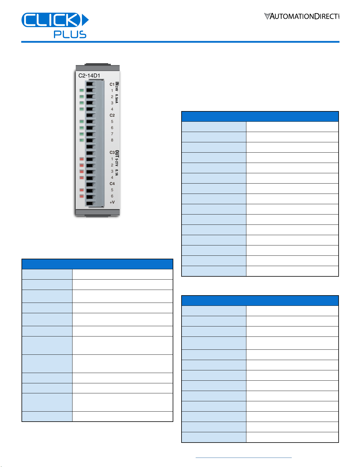
C2-14D1 Option Slot Module
+V
6
5
C4
4
3
2
1
C3
5
-
27V 0.1A
OUT
8
7
6
5
C2
4
3
2
1
C1
24V 6.5mA
IN
C2-14D1
Installation Instructions
C2-14D1 OPTION SLOT MODULE
8 discrete DC sinking/sourcing inputs
6 discrete DC sinking outputs
General Specifications*
Operating Temperature
Storage Temperature
Ambient Humidity
Altitude
Environmental Air
Environment
Vibration
Shock
Weight
Bus Power Required
Agency Approvals
Other
* Isolate from shock, vibration and electric or ferromagnetic eld.
Keep out iron powder, moisture, oil or chemicals.
Indoor use only. Keep out of direct sunlight.
Copyright© 2020, Automationdirect.com Incorporated/All Rights Reserved Worldwide
32°F to 131°F [0°C to 55°C]
–4°F to 158°F [–20°C to 70°C]
30% to 95% relative humidity
(non–condensing)
Up to 2,000m
No corrosive gases
Pollution Degree 2 (UL840)
For Indoor Use Only
5–9Hz: 3.5 mm amplitude; 9–150Hz: 1.0 G
10 sweep cycles per axis on each of
3 mutually perpendicular axes.
15G peak, 11ms duration,
3 shocks in each direction per axis,
on 3 mutually perpendicular axes.
48g
Max 50mA (all points ON)
UL61010 (File No. E157382);
CE (EN61131-2);
CUL Canadian C22.2
RoHS 2011/65/EU Amendment (EU)2015/863
3505 HUTCHINSON ROAD
CUMMING, GA 30040-5860
1-800-633-0405
Please read and understand the information in these
installation instructions prior to installation, operation, or
servicing this equipment. This module is intended to be used
with a CLICK PLUS CPU. Ensure the CPU is installed in
accordance with its installation and safety instructions.
PLEASE REVIEW SAFETY WARNINGS ON PAGE 2!
Input Specifications
Inputs per Module
Nominal Voltage
Input Voltage Range
Input Current
Max. Input Current
Input Impedance
ON Voltage Level
OFF Voltage Level
Minimum ON Current
Maximum OFF Current
OFF to ON Response
ON to OFF Response
Input Filter
Status Indicators
Commons
* Set from CLICK Tool.
8 (Source/Sink)
24.0 VDC
21.6–26.4 VDC
6.5 mA @ 24VDC, typical
7mA @ 26.4 VDC
3.9 kΩ @ 24VDC
> 19.0 VDC
< 2.0 VDC
4.5 mA
0.5 mA
3μs typical, 5μs maximum
1μs typical, 5μs maximum
1ms unit (set from 1 to 99 ms)*
8 Green LEDs
2 (4 points/common) Isolated
Output Specifications
Outputs per Module
Operating Voltage Range
Output Voltage Range
Max. Output Current
Min. Output Current
Max. Leakage Current
ON Voltage Drop
Max. Inrush Current
OFF to ON Response
ON to OFF Response
Status Indicators
Commons
External DC Power Required
6 (Sink)
5–27 VDC
4–30 VDC
0.1 A/point,
0.4 A/common (C3), 0.2 A/common (C4)
0.2 mA
0.1 mA @ 30VDC
0.5 VDC @ 0.1 A
150mA for 10ms
< 5μs (Duty 40–60%, Load current 20mA)
< 5μs (Duty 40–60%, Load current 20mA)
6 Red LEDs
2 (4 points or 2 points/common) Isolated
20–28 VDC, Max 60mA (all points on)
www.automationdirect.com/click-plc
1
Page 2
C2-14D1 Option Slot Module
3 Push the top and bottom locking clips
backward until they click into place.
1 Remove the Option Slot Cover (#C2-FILL)
if it was installed in the CPU, by grasping its
top and bottom front corners, squeezing and
pulling it forward.
3 Push the top and bottom locking clips
backward until they click into place.
Lift slightly on the locking clips until they
release, then slide each clip forward.
Reverse the procedure.
To install an Option Slot Module To install an Option Slot Module
To remove an Option Slot Module
To remove an Option Slot Module
3 Push the top and bottom locking clips
backward until they click into place.
Installation Instructions
3505 HUTCHINSON ROAD
CUMMING, GA 30040-5860
1-800-633-0405
Safety Warnings
Please follow these instructions for personal and operational safety.
WARNING
CAUTION
Don’t use this equipment in a flammable or explosive
environment in order to avoid accidental injury or fire.
You should use external electromechanical devices that are
independent of the PLC (Programmable Logic Controller)
system to provide protection for any part of the system;
otherwise malfunction or output failures may result in a
hazardous accident.
24VDC power is required from a secondary circuit or a specific
power supply unit only.
Ensure the Ground Terminal of the Power Supply (C0-00AC/
C0-01AC) for the CLICK PLUS CPU is connected to Earth
Ground to avoid electric shock or equipment damage during a
short circuit.
Don’t operate the equipment with a nonconforming external
power supply to avoid electric shock, equipment damage or fire.
Don’t intentionally fault the wiring; this may cause equipment
damage or fire.
To avoid electric shock or malfunctions which might result in an
accident, don’t touch any terminal while the PLC power is on.
Don’t put metals (e.g. screwdriver) into vent holes, or drop trash
or foreign objects (e.g. wire cut-offs) into the device, in order to
avoid electric shock or equipment damage.
If the equipment is used in a manner not specified by the
manufacturer, the protection provided by the equipment may be
invalidated.
Assumes that incorrect handling may cause hazardous
conditions, resulting in severe injury or death.
Assumes that incorrect handling may cause hazardous
conditions, resulting in medium or slight injury, or
may cause equipment damage.
WARNING
Hardware Installation
CAUTION
CAUTION
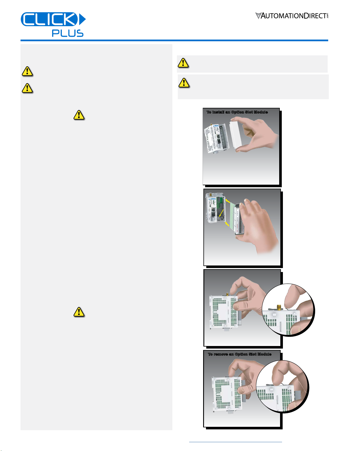
INSTALL OR REMOVE THE OPTION SLOT MODULE
Discharge static electricity before installation or
wiring to avoid electric equipment damage.
Cut off all phases of the power source externally
and wait 5 seconds before installing or removing
the Option Slot Module of a running system.
To install an Option Slot Module To install an Option Slot Module
1 Remove the Option Slot Cover (#C2-FILL)
if it was installed in the CPU, by grasping its
top and bottom front corners, squeezing and
pulling it forward.
2 Hold the
Option Slot
Module by the
top and bottom front
corners, align the PCB card
edge with the guide slots in the
CPU, and slide the module into
its slot. Press the module into place until it is
fully seated
CAUTION
For use in Pollution Degree 2 Environment. Use and store the
equipment in an environment described in the specifications
(regarding temperature, humidity, vibrations, shock, etc.) in
order to avoid equipment damage or fire.
Ensure all wiring has strain reliefs in order to avoid damage to
insulation that might result in electric shock or fire.
Ensure secondary external power circuits are only live after PLC
control program is started; otherwise a malfunction or output
failure may result in a hazardous accident.
Don’t block the vent holes. This may cause an increase of inter-
nal temperature resulting in equipment damage or fire.
Don’t disassemble or modify equipment so as to avoid electric
shock, equipment damage, or fire.
Cut off all phases of the external power source before mainte-
nance work, thus avoiding electric shock or equipment damage.
Copyright© 2020, Automationdirect.com Incorporated/All Rights Reserved Worldwide
www.automationdirect.com/click-plc
3 Push the top and bottom locking clips
backward until they click into place.
To remove an Option Slot Module
To remove an Option Slot Module
Lift slightly on the locking clips until they
release, then slide each clip forward.
Reverse the procedure.
2
Page 3

C2-14D1 Option Slot Module
+
Equivalent Discrete Input Circuit
Equivalent Discrete Output Circuit
Installation Instructions
Hardware Installation, continued
3505 HUTCHINSON ROAD
CUMMING, GA 30040-5860
1-800-633-0405
WIRING
16–28 AWG wiring is supported. We recommend using
crimping ferrules on all wire terminations for a more secure
connection. The following crimping ferrules are recommended
for the I/O terminals.
Company
AutomationDirect
* Rated torque is 0.22 to 0.25 N·m.
Take care not to contact adjacent terminal.
Connector Type
Number of Pins
Pitch
Wire Size Range
Stripping Length
Wire Specication
Screw Thread
Tightening Torque
Type Model No. Compliant Wire
Ferrule
V30AE000009
V30AE000041
0.2–0.5 mm2 (22–26AWG)
Terminal Block Specifications
Pluggable Terminal Block
20
3.50 mm
16–28 AWG
7.0 mm
Lead-free, heat resistant,
polyvinyl chloride insulated copper wire,
rated over 80°C
M2.0
2.0–2.2 inch-lb [0.22–0.25 N·m]
WIRING DIAGRAM
C2-14D1
C1
1
2
3
4
C2
5
6
7
8
C3
1
2
3
4
C4
5
6
+V
IN
24V 6.5mA
OUT
5
-
27V 0.1A
24VDC
++
+ +
L
L
L
L
L
L
+
5 - 27VDC
+
5 - 27VDC
+
24VDC
EQUIVALENT CIRCUITS
3.3 V
Internal Module Circuitry
24 VDC
+
24VDC
+
+
L
5–27
VDC
INPUT
COM
+V
OUTPUT
COM
Internal Module Circuitry
Optical Isolator
VCC
GND
3.3 V
Optical Isolator
VCC
GND
Copyright© 2020, Automationdirect.com Incorporated/All Rights Reserved Worldwide
www.automationdirect.com/click-plc
3
Page 4

C2-14D1 Option Slot Module
Surrounding Air Temperature (°C/°F)
°F
Points
Inputs Temperature Derating Chart
°F
Surrounding Air Temperature (°C/°F)
Points
Outputs Temperature Derating Chart
Installation Instructions
Hardware Installation, continued
DERATING CHARTS
8
6
4
2
3505 HUTCHINSON ROAD
CUMMING, GA 30040-5860
1-800-633-0405
0
0
32
8
6
4
2
0
0
32
10
50
10
50
20
68
20
68
30
85
30
85
40
104
40
104
45
45
50
122
50
122
55 °C
131
55 °C
131
Symbols listed on the equipment are shown below.
Name
DC
CAUTION
Copyright© 2020, Automationdirect.com Incorporated/All Rights Reserved Worldwide
Description Symbol
DC power supply IEC60417 No. 5031
Use Copper Conductor Only ISO 7000 No.0434B
For additional technical support or
questions, call our Technical Support team
at 1-800-633-0405 or 770-844-4200.
www.automationdirect.com/click-plc
4
 Loading...