

Page 1
1-800-633-0405
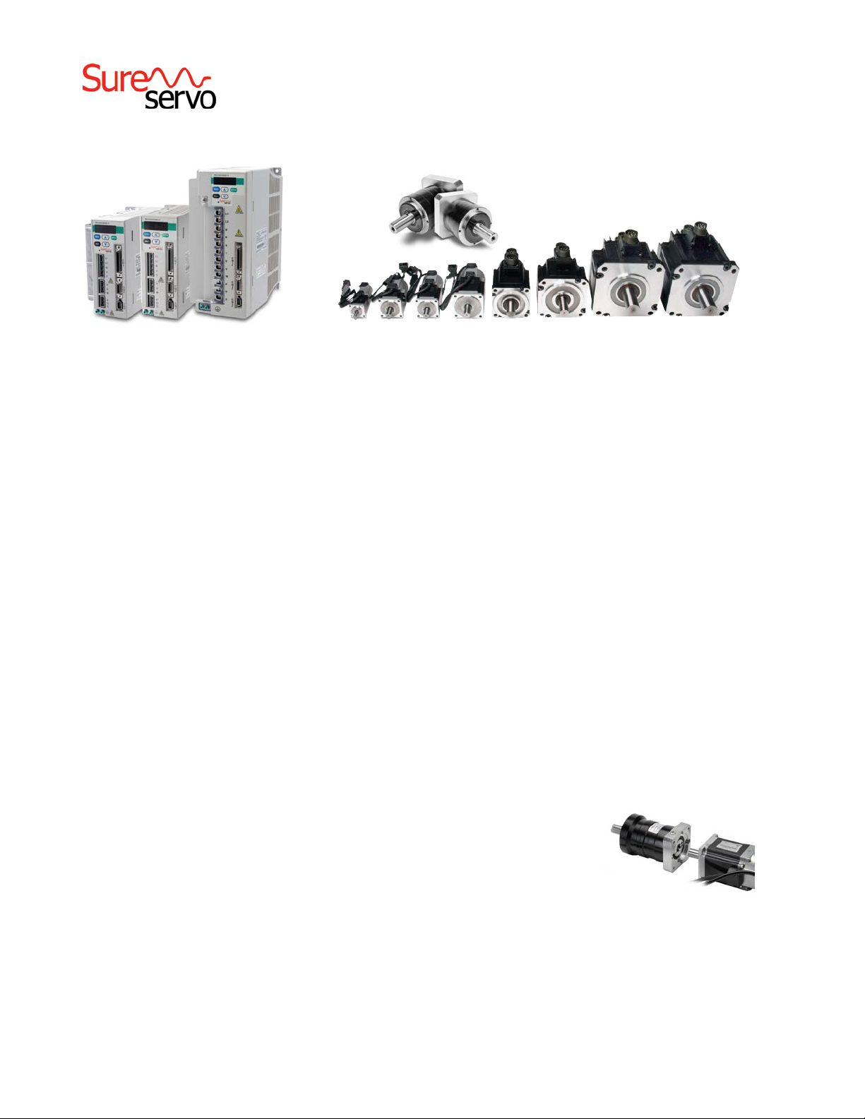
3 Standard Drives ... 8 Standard Motors ... 100W to 3kW
... over 50 gearboxes (both inline and right angle) with four ratios
For the latest prices, please check AutomationDirect.com.
®
AC Servo Systems
Drive features
• Main Power and Control Power Inputs
» Main Power: 230 VAC 1-phase/3-phase (2kW and 3kW systems
are 3-phase only)
» Control Power: 230 VAC Single Phase; 50/60 Hz
• Fully digital with up to 450 Hz velocity loop response
• Easy setup and diagnostics with built-in keypad/display or the
SureServo Pro PC-based software
• Five-in-one command options include:
» ± 10V torque or velocity command
» Pulse train or master encoder position command (accepts
line driver or open collector) with electronic gearing
» Built-in indexer for position control using 8 preset positions
and/or position setpoint with serial Modbus
• Tuning aids include inertia estimation and easy tuning for up to 10
levels of response
• Optically isolated digital inputs (8) and outputs (5), analog outputs
for monitor signals (2), and line driver output for encoder (with
scalable resolution)
SureServo
SureServo
tuning technology
The SureServo drive closes the loop on
current, velocity, and position
(depending on control mode selection).
Proportional gain, integral gain, feed
forward compensation, command low
pass filter, and a notch filter for resonance suppression are available. There
are three tuning modes:
1. “Manual Mode” for user-defined
adjustments
2. “Easy Mode” for default settings over
a wide range of programmed inertia
with 10 response levels
3. “Auto Mode” for automatic adjust-
ment using an estimated (or
measured) value of inertia
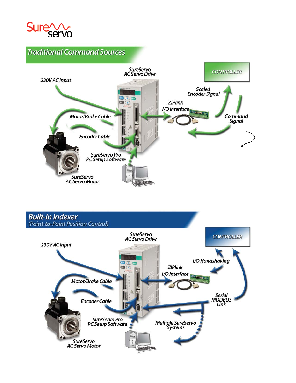
built-in motion controller
While the SureServo drives can accept
traditional commands from host controls,
they can also provide their own internal
motion control. For example, up to
eight index moves can be pre-defined
and stored in the drive and then selected
and executed using up to three discrete
inputs. The predefined index profiles can
also be changed via serial communications. The motion can be incremental or
absolute (homing routines are available
in the drive) and acceleration can be
linear or S-curve.
Multiple drives can be daisy-chained
and addressed separately using the
drive’s serial port. This allows very
simple yet powerful control of multi-axis
processes that do not need precise path
control but only precise starting and stopping points. Applications include press
feeds, auger fillers, rotary tables, robots
for pick and place, test or assembly
operations, drilling, cutting, tapping, and
similar applications using simple index
moves for single or multi-axis motion.
Motor features
• Low inertia models:
» 100W, 200W, 400W, 750W and 1kW
» Speeds up to 5,000 rpm.
• Medium inertia models:
» 1kW, 2kW and 3kW
» Speeds up to 3,000 rpm.
• Square flange mounting with metric dimensions:
» 40, 60, 80, 100, 130 and 180 mm flanges
• Permanent magnet 3-phase synchronous motor
• Keyless drive shafts support clamp-on style coupling
• Integrated encoder with 2,500 (x4) pulses/revolution plus marker
pulse (once per revolution)
• Optional 24 VDC spring-set holding brakes
• Standard hook-up cables for motor power/brake and encoder
• Standard DIN-rail mounted ZIPLink break-out kit for the drive’s
CN1 connector (with screw terminal connections)
SureServo
Optional Holding Brake
Each SureServo motor can be ordered
with an optional 24VDC spring-set
holding brake that holds the motor in
place when power is removed.
SureGear® Precision
Gearboxes for
Servo motors
Inertia
balancing
issue in
your design?
The SureGear PGA
series easily mates to SureServo
motors. Everything you need to mount
your SureServo motor is included!
• Four gear ratios available (5, 10, 15, 25:1)
• Mounting hardware included for attaching
to SureServo motors
• Industry-standard mounting dimensions
• Thread-in mounting style
• Best-in-class backlash (5 arc-min)
• 5-year warranty
www.automationdirect.com
Motion Control
tMNC-166
Page 2
1-800-633-0405
For the latest prices, please check AutomationDirect.com.
For the latest prices, please check AutomationDirect.com.
®
AC Servo Systems
• Pulse Train Positions:
• Step and direction
• CW and CCW
• Encoder follower
• Analog Velocity (±10V)
• Analog Torque (±10V)
• Mode Switching
• “On-the-Fly” Control Mode
Switching
mMNC-6
www.automationdirect.com
Motion Control
Stand-alone operation
using internal presets
• Preset selection with
digital inputs
• Ability to change preset
values with serial bus
(RTU/ASCII Modbus
protocols)
1-800-633-0405
Motion Control
tMNC-167
Page 3
1-800-633-0405
®
AC Servo Systems
How to select and apply SureServo systems
The primary purpose of the AC servo system is to precisely
control the motion of the load. The most fundamental
considerations in selecting the servo system are
“reflected” load inertia, servo system maximum speed
requirement, servo system continuous torque requirement, and servo system peak torque requirement. In a
retrofit application, select the largest torque SureServo
system that most closely matches these parameters for
Motion Profile
Desired
Load
Velocity
Required
Motor
Torque
time
For the latest prices, please check AutomationDirect.com.
the system being replaced. In a new application, these
parameters should be determined through calculation and/or
measurement.
AutomationDirect has teamed with Copperhill Technologies
to provide free servo-sizing software. “VisualSizer-SureServo”
software will assist in determining the correct motor and drive
for your application by calculating the reflected load inertia
and required speed and torque based on the load configuration. “VisualSizer-SureServo” software can be downloaded
from www.sureservo.com/downloads.htm.
Information for selecting SureServo systems is also included
in Appendix B of the SureServo User Manual, which can be
downloaded from the AutomationDirect.com website.
Servo
System
Mechanical
Transmission
Load
1. “Reflected” load inertia
The inertia of everything attached to the servo motor driveshaft needs to be considered and the total “reflected” inertia
needs to be determined. This means that all elements of any
mechanical transmission and load inertia need to be translated into an equivalent inertia as if attached directly to the
motor driveshaft. The ratio of “reflected” load inertia to motor
inertia needs to be carefully considered when selecting the
servo system.
In general, applications that need high response or bandwidth will benefit from keeping the ratio of load inertia to
motor inertia as low as possible and ideally under 10:1.
Systems with ratios as high as 200:1 can be implemented,
but corresponding lower bandwidth or responsiveness must
be accepted. The servo response including the attached load
inertia is determined by the servo tuning. SureServo systems
may be tuned manually, adaptively with measurement of the
load inertia, or set with default tuning based on a programmed
value of load inertia.
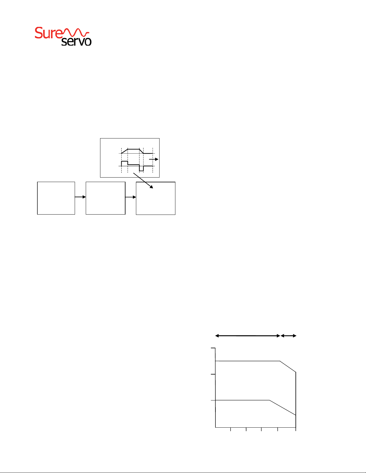
2. Torque and speed
With knowledge of the motion profile and any mechanical transmission between the motor and load, calculations can be made to determine the required servo motor continuous torque, peak torque, and
maximum motor speed. The required amount of continuous torque
must fall inside the continuous operating region of the system torquespeed curve (you can check the continuous torque at the average
speed of the motion profile). The required amount of peak torque
must also fall within the servo system’s intermittent operating region
of the system torque-speed curve (you need to check this value at the
required maximum speed).
300%
Torque
200%
100%
Peak Torque
Limited by Current
Limit
Intermittent Operating
Region
Continuous Operating
Region
Limited by Voltage
Peak Torque
Limit
www.automationdirect.com
1000 2000 3000 4000
Speed (r.p.m.)
Motion Control
5000
tMNC-168
Page 4

1-800-633-0405
®
For the latest prices, please check AutomationDirect.com.
AC Servo Systems
Application tip -
coupling considerations
The SureServo motors have keyless shafts that are designed for
use with clamp-on or compression style couplings. Couplings
using keys and/or set screws should NOT be used with
SureServo motors as they are likely to come loose or damage
the motor shaft. “Servo-grade” clamp-on or compression
style couplings are usually the best choice when you consider
Coupling Suppliers: www.sureservo.com/couplingconsiderations.htm
Mechanical transmissions
Common mechanical transmissions include leadscrews, rack
& pinion mechanisms, conveyors, gears, and timing belts. The
use of leadscrew, rack & pinion, or conveyor are common
the stiffness, torque rating, and inertia. Higher stiffness
(lb-in/radian) is needed for better response but there is a
trade-off between the stiffness and the added inertia of the
coupling. Concerning the torque rating of the coupling, use a
safety factor of 1.25 over the SureServo peak torque requirement of your application.
ways to translate the rotary motion of the servo motor into
linear motion of the load. The use of a speed reducer such
as a gearbox or timing belt can be very beneficial as follows:
1. Reduction of reflected
load inertia
As a general rule, it is beneficial to
keep the reflected load inertia as low as
possible while using the full range of servo
speed. SureServo systems can go up to
5,000 rpm for the low inertia motors and
up to 3,000 rpm for the medium inertia
motors.
Example: A gearbox reduces the required
torque by a factor of the gear ratio, and
reduces the reflected load inertia by a
factor of the gear ratio squared. A 10:1
gearbox reduces output speed to 1/10,
increases output torque 10 times, and
decreases reflected inertia to 1/100.
However, when investigating the effect
of different speed reduction ratios DO
NOT forget to include the added inertia
of couplings, gearbox, or timing belt
pulleys. These added inertias can be
significant, and can negate any inertia
reduction due to the speed reduction.
www.sureservo.com/mechanical_trans.htm
2. Low speed and high torque
applications
If the application requires low speed and
high torque then it is common to introduce a speed reducer so that the servo
system can operate over more of the
available speed range. This could also
have the added benefit of reducing the
servo motor torque requirement which
could allow you to use a smaller and
lower cost servo system. Additional
benefits are also possible with reduction
in reflected inertia, increased number of
motor encoder counts at the load, and
increased ability to reject load disturbances due to mechanical advantage of
the speed reducer.
3. Space limitations and motor
orientation
SureServo motors can be mounted in
any orientation, but the shaft seal should
not be immersed in oil (open-frame
gearbox, etc.). Reducers can possibly
allow the use of a smaller motor or
allow the motor to be repositioned. For
example, some reducers would allow for
in-line, right angle, or parallel mounting
of the motor.
For more information, refer to the
website listed below.
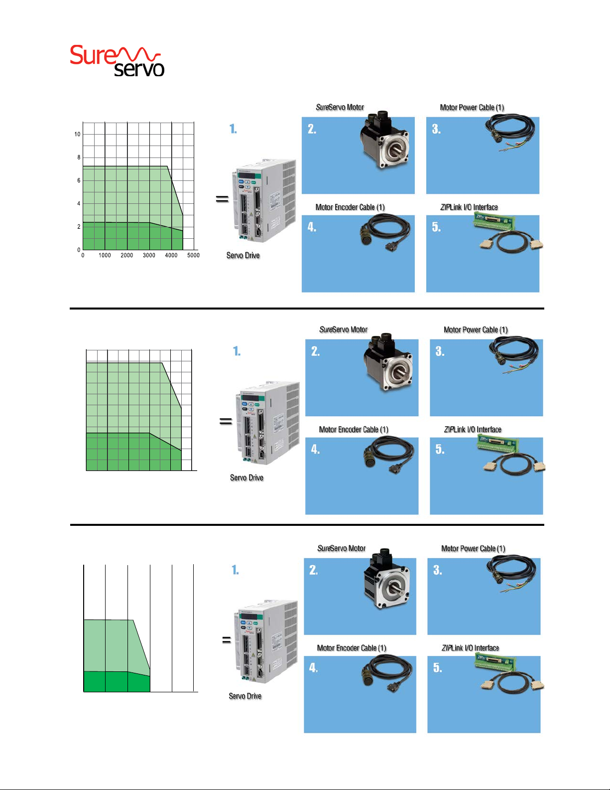
Ordering guide instructions
The following four pages are your ordering guide for the
eight standard SureServo systems. Each of the eight standard
systems has a torque-speed curve including the motor inertia
for reference. This is the fundamental information that you
need to select the servo drive and matching motor for your
application.
www.automationdirect.com
Don’t forget the cables and ZIPLink break-out board kit!
Included in the ordering guide are the available connection
cables from the drive to motor in standard lengths from 10 to
60 feet. The break-out board kit includes a 0.5m (19 inch)
cable for the CN1 I/O interface, and is listed for your convenience. We highly recommend all five items per system as a
minimum. All cables are 100% factory tested to make your
system installation as easy and quick as possible. See the
Accessories section for regeneration resistors, AC line filters,
fuses, contactors, and RF noise filters.
Motion Control
tMNC-169
Page 5

SV A - 2 04 0
2: 230VAC; 50/60 Hz
1-800-633-0405
®
AC Servo System Configuration
SureServo series drives and motors part numbering system
For the latest prices, please check AutomationDirect.com.
Series
SV: SureServo AC servo
Component Type
A: Drive
L: Low inertia motor
M: Medium inertia motor
Component Option
0: Drive
Blank: Motor without brake
B: Motor with brake
Rated Output Power
01: 100W 10: 1000W
02: 200W 20: 2000W
04: 400W 30: 3000W
07: 750W
Nominal Input Voltage
Here is what you will need to order a complete servo system:
Servo Drive
Servo Motor Motor Power
Cable
Motor Encoder
Cable
ZIPLink I/O
Interface
Note: uNit caN be programmed via keypad.
optioNal programmiNg software (free dowNload) aNd optioNal programmiNg cable available.
Note: if you Need a gear box for your coNfiguratioN, you caN do it easily oNliNe:
http://www.sureservo.com/gearbox/selector
SureServo AC servo drive, motor, and cable combinations
Inertia
& Power
Inertia
Low inertia
Medium inertia
Drive and Motor
Servo
Servo
Motor
Motor
without
Power
Servo Drive
100W
200W SVL-202 SVL-202B
400W SVL-204 SVL-204B
750W
1000W SVL-210 SVL-210B
1000W SVM-210 SVM-210B
2000W
3000W SVM-230 SVM-230B
SVA-2040
SVA-2100
SVA-2300
with
brake
brake
(note)
(note)
SVL-201 SVL-201B
SVL-207 SVL-207B
SVM-220 SVM-220B
10 ft 20 ft 30 ft 60 ft 10 ft 20 ft 30 ft 60 ft
SVCPFL-010
SVCPHM-010
SVCPHH-010
Note: each servo motor requires aN eNcoder feedback cable aNd a power cable.
the motor power cable iNcludes brake power wires for the optioNal motor brake.
Power Cables
(from Drive to Motor)
SVC-
SVCPFL-030
SVCPHM-030
SVCPHH-030
SVCPFL-060
SVCPHM-060
SVCPHH-060
PFL-020
SVCPHM-020
SVCPHH-020
Encoder Feedback Cables Miscellaneous
SVCEFL-010
SVCEHH-010
SVCEFL-020
SVCEHH-020
SVCEFL-030
SVCEHH-030
SVCEFL-060
SVCEHH-060
ZIPLink I/O
Interface
ZL-RTB50
and
ZL-SVC-CBL50
or
ZL-SVC-CBL50-1
or
ZL-SVC-CBL50-2
RS-422/485
Serial Communication
Cable
SVC-MDCOM-CBL
www.automationdirect.com
Motion Control
tMNC-170
Page 6

Torque
Torque
(rpm)
Torque
Torque
Torque
1-800-633-0405
100W Low Inertia System
(N-m)
For the latest prices, please check AutomationDirect.com.
®
AC Servo System Configuration
For all systems:
Order programming software &
programming cable if needed.
See pgs. tMNC-171 & 45.
Torque
(in-lb)
8.9
7.1
Intermittent
Duty Zone
Continuous
5.3
3.5
1.8
Duty Zone
0
100W Low Inertia
Speed
(rpm)
SVA-2040 $483.00
Jm= Motor Inertia = 0.000027 lb-in-s2 (0.000003 kg - m2)
200W Low Inertia System
(N·m)
2.5
2.0
1.5
1.0
0.5
Intermittent
Duty Zone
Continuous Duty Zone
0
0
1000 2000
3000 4000
200W Low Inertia
Jm= Motor Inertia = 0.00016 lb-in-s2 (0.000018 kg - m2)
(in·lb)
5000
Speed
22.1
17.7
13.3
8.9
4.4
0
SVA-2040 $483.00
SVL-201 $322.00
SVL-201B (w/brake) $567.00
SVC-EFL-010 (10’) $56.00
SVC-EFL-020 (20’) $92.00
SVC-EFL-030 (30’) $108.00
SVC-EFL-060 (60’) $137.00
SVL-202 $425.00
SVL-202B (w/brake) $629.00
SVC-EFL-010 (10’) $56.00
SVC-EFL-020 (20’) $92.00
SVC-EFL-030 (30’) $108.00
SVC-EFL-060 (60’) $137.00
SVC-PFL-010 (10’) $33.50
SVC-PFL-020 (20’) $63.00
SVC-PFL-030 (30’) $79.00
SVC-PFL-060 (60’) $143.00
ZL-RTB50 $52.00
and one cable below:
ZL-SVC-CBL50 (0.5m) $34.00
ZL-SVC-CBL50-1 (1m) $35.00
ZL-SVC-CBL50-2 (2m) $40.50
SVC-PFL-010 (10’) $33.50
SVC-PFL-020 (20’) $63.00
SVC-PFL-030 (30’) $79.00
SVC-PFL-060 (60’) $143.00
ZL-RTB50 $52.00
and one cable below:
ZL-SVC-CBL50 (0.5m) $34.00
ZL-SVC-CBL50-1 (1m) $35.00
ZL-SVC-CBL50-2 (2m) $40.50
400W Low Inertia System
35.4
26.6
17.7
Speed
(rpm)
(in-lb)
44.3
8.9
0
(N·m)
Intermittent
Duty Zone
Continuous
Duty Zone
400W Low Inertia
Jm= Motor Inertia =0.0003 lb-in-s2 (0 .000034 kg - m2)
www.automationdirect.com
SVA-2040 $483.00
SVL-204 $520.00
SVL-204B (w/brake) $733.00
SVC-EFL-010 (10’) $56.00
SVC-EFL-020 (20’) $92.00
SVC-EFL-030 (30’) $108.00
SVC-EFL-060 (60’) $137.00
SVC-PFL-010 (10’) $33.50
SVC-PFL-020 (20’) $63.00
SVC-PFL-030 (30’) $79.00
SVC-PFL-060 (60’) $143.00
ZL-RTB50 $52.00
and one cable below:
ZL-SVC-CBL50 (0.5m) $34.00
ZL-SVC-CBL50-1 (1m) $35.00
ZL-SVC-CBL50-2 (2m) $40.50
Motion Control
tMNC-171
Page 7
Torque
(rpm)
Torque
(rpm)
Torque
10.0
17.7
35.4
53.1
70.8
88.5
1-800-633-0405
750W Low Inertia System
(N-m)
For the latest prices, please check AutomationDirect.com.
®
AC Servo System Configuration
For all systems:
Order programming software &
programming cable if needed.
Torque
See pgs. tMNC-172 & 45.
(in-lb)
88.5
70.8
Intermittent
Duty Zone
Continuous
Duty Zone
750W Low Inertia
53.1
35.4
17.7
0
Speed
Jm= Motor Inertia = .00096 lb-in-s2 (0.000108 kg - m2)
1 kW Low Inertia System
8.0
6.0
4.0
Torque
(N·m)
Intermittent
Duty Zone
Torque
(in·lb)
SVA-2100 $683.00
SVL-207 $556.00
SVL-207B (w/brake) $794.00
SVC-EFL-010 (10’) $56.00
SVC-EFL-020 (20’) $92.00
SVC-EFL-030 (30’) $108.00
SVC-EFL-060 (60’) $137.00
SVL-210 $663.00
SVL-210B (w/brake) $993.00
SVC-PFL-010 (10’) $33.50
SVC-PFL-020 (20’) $63.00
SVC-PFL-030 (30’) $79.00
SVC-PFL-060 (60’) $143.00
ZL-RTB50 $52.00
and one cable below:
ZL-SVC-CBL50 (0.5m) $34.00
ZL-SVC-CBL50-1 (1m) $35.00
ZL-SVC-CBL50-2 (2m) $40.50
SVC-PHM-010 (10’) $105.00
SVC-PHM-020 (20’) $114.00
SVC-PHM-030 (30’) $190.00
SVC-PHM-060 (60’) $224.00
Continuous
2.0
Duty Zone
0
1000
0
2000 3000 4000
1 kW Low Inertia
Jm= Motor Inertia = .0023 lb-in-s2 (0.00026 kg - m2)
5000
Speed
(rpm)
0
SVA-2100 $683.00
1 kW Medium Inertia System
(N-m)
......................................................................
......................................................................
25
......................................................................
......................................................................
20
......................................................................
......................................................................
15
......................................................................
Intermittent
......................................................................
10
......................................................................
Duty Zone
......................................................................
5
Continuous
......................................................................
Duty Zone
................................................................................
0
0 1000 2000 3000 4000 5000
1 kW Medium Inertia
Jm= Motor Inertia = .0053 lb-in-s2 (0.000598 kg - m2)
................................................................................
................................................................................
................................................................................
(in-lb)
221.3
177.0
132.8
88.5
44.3
................................................................................
0
Speed
SVA-2100 $683.00
SVC-EHH-010 (10’) $99.00
SVC-EHH-020 (20’) $112.00
SVC-EHH-030 (30’) $125.00
SVC-EHH-060 (60’) $163.00
SVM-210 $852.00
SVM-210B (w/brake) $1,184.00
SVC-EHH-010 (10’) $99.00
SVC-EHH-020 (20’) $112.00
SVC-EHH-030 (30’) $125.00
SVC-EHH-060 (60’) $163.00
ZL-RTB50 $52.00
and one cable below:
ZL-SVC-CBL50 (0.5m) $34.00
ZL-SVC-CBL50-1 (1m) $35.00
ZL-SVC-CBL50-2 (2m) $40.50
SVC-PHM-010 (10’) $105.00
SVC-PHM-020 (20’) $114.00
SVC-PHM-030 (30’) $190.00
SVC-PHM-060 (60’) $224.00
ZL-RTB50 $52.00
and one cable below:
ZL-SVC-CBL50 (0.5m) $34.00
ZL-SVC-CBL50-1 (1m) $35.00
ZL-SVC-CBL50-2 (2m) $40.50
www.automationdirect.com
Motion Control
tMNC-172
Page 8

(rpm)
Torque
1-800-633-0405
®
AC Servo System Configuration
2 kW Medium Inertia System
(N-m)
......................................................................
......................................................................
25
......................................................................
......................................................................
20
......................................................................
Intermittent
......................................................................
15
Duty Zone
......................................................................
......................................................................
10
......................................................................
......................................................................
Continuous
5
Duty Zone
......................................................................
................................................................................
................................................................................
................................................................................
................................................................................
0
0 1000 2000 3000 4000 5000
2 kW Medium Inertia
Jm= Motor Inertia = .014 lb-in-s2 = (0.00158 kg - m2)
................................................................................
Speed
For all systems:
Order programming software &
programming cable if needed.
See pgs. 44 & 45.
Torque
(in-lb)
221.3
177.0
132.8
88.5
44.3
0
SVA-2300 $1,140.00
SVM-220 $900.00
SVM-220B (w/brake) $1,231.00
SVC-EHH-010 (10’) $99.00
SVC-EHH-020 (20’) $112.00
SVC-EHH-030 (30’) $125.00
SVC-EHH-060 (60’) $163.00
For the latest prices, please check AutomationDirect.com.
SVC-PHH-010 (10’) $126.00
SVC-PHH-020 (20’) $165.00
SVC-PHH-030 (30’) $204.00
SVC-PHH-060 (60’) $332.00
ZL-RTB50 $52.00
and one cable below:
ZL-SVC-CBL50 (0.5m) $34.00
ZL-SVC-CBL50-1 (1m) $35.00
ZL-SVC-CBL50-2 (2m) $40.50
3 kW Medium Inertia System
Torque
(N-m)
......................................................................
......................................................................
50
......................................................................
......................................................................
40
......................................................................
......................................................................
30
Intermittent
......................................................................
Duty Zone
......................................................................
20
......................................................................
......................................................................
10
Continuous
......................................................................
Duty Zone
................................................................................
................................................................................
0
0 1000 2000 3000 4000 5000
................................................................................
................................................................................
3 kW Medium Inertia
Jm= Motor Inertia = 0.038 lb-in-s2 = (0.00433 kg - m2)
Torque
(in-lb)
442.5
354.0
SVM-230 $1,373.00
265.5
177.0
88.5
................................................................................
0
Speed
(rpm)
SVA-2300 $1,140.00
SVM-230B (w/brake) $1,567.00
SVC-EHH-010 (10’) $99.00
SVC-EHH-020 (20’) $112.00
SVC-EHH-030 (30’) $125.00
SVC-EHH-060 (60’) $163.00
SVC-PHH-010 (10’) $126.00
SVC-PHH-020 (20’) $165.00
SVC-PHH-030 (30’) $204.00
SVC-PHH-060 (60’) $332.00
ZL-RTB50 $52.00
and one cable below:
ZL-SVC-CBL50 (0.5m) $34.00
ZL-SVC-CBL50-1 (1m) $35.00
ZL-SVC-CBL50-2 (2m) $40.50
Note: all motor power cables iNclude brake
power wires for the optioNal motor brake.
SureServo Communications Cables for Muti-drop Networks
Product Price Description
RS-422/485 serial communication cable for use with multidrop networks; 3ft length; IEEE 1394
plug to unterminated wires; compatible with all SureServo systems.
SVC-MDCOM-CBL
SVC-232RJ12-CBL-2 *
SVC-485RJ12-CBL-2 *
SVC-485HD15-CBL-2 *
* Refer to the ZIPLinks Wiring Solutions section for complete information regarding the ZIPLink cables.
$28.00
Facilitates connection between the SureServo drive serial port and host controllers.
ZIPLink SureServo Drives cable with 6-pin RJ12 connector to a 6-pin IEEE 1394 connector, shield-
$8.50
ed, twisted pair, 2.0 meter (6.6 ft.) length. For RS-232 connection to all SureServo amplifiers.
ZIPLink SureServo amplifier communication cable, RJ12 male to 6-pin IEEE 1394 connector,
$10.00
shielded, twisted pair, 2.0 meter (6.6 ft.) length. Cable used in conjunction with ZL-CDM-RJ12xxx
distribution module can access a compatible RS-485 device network.
ZIPLink SureServo Drives cable with a HD 15-pin male to a 6-pin IEEE 1394 connector, shielded,
$9.00
twisted pair, 2.0 meter (6.6 ft.) length. For RS-485 connection to all SureServo amplifiers.
www.automationdirect.com
Motion Control
tMNC-173
Page 9
1-800-633-0405
®
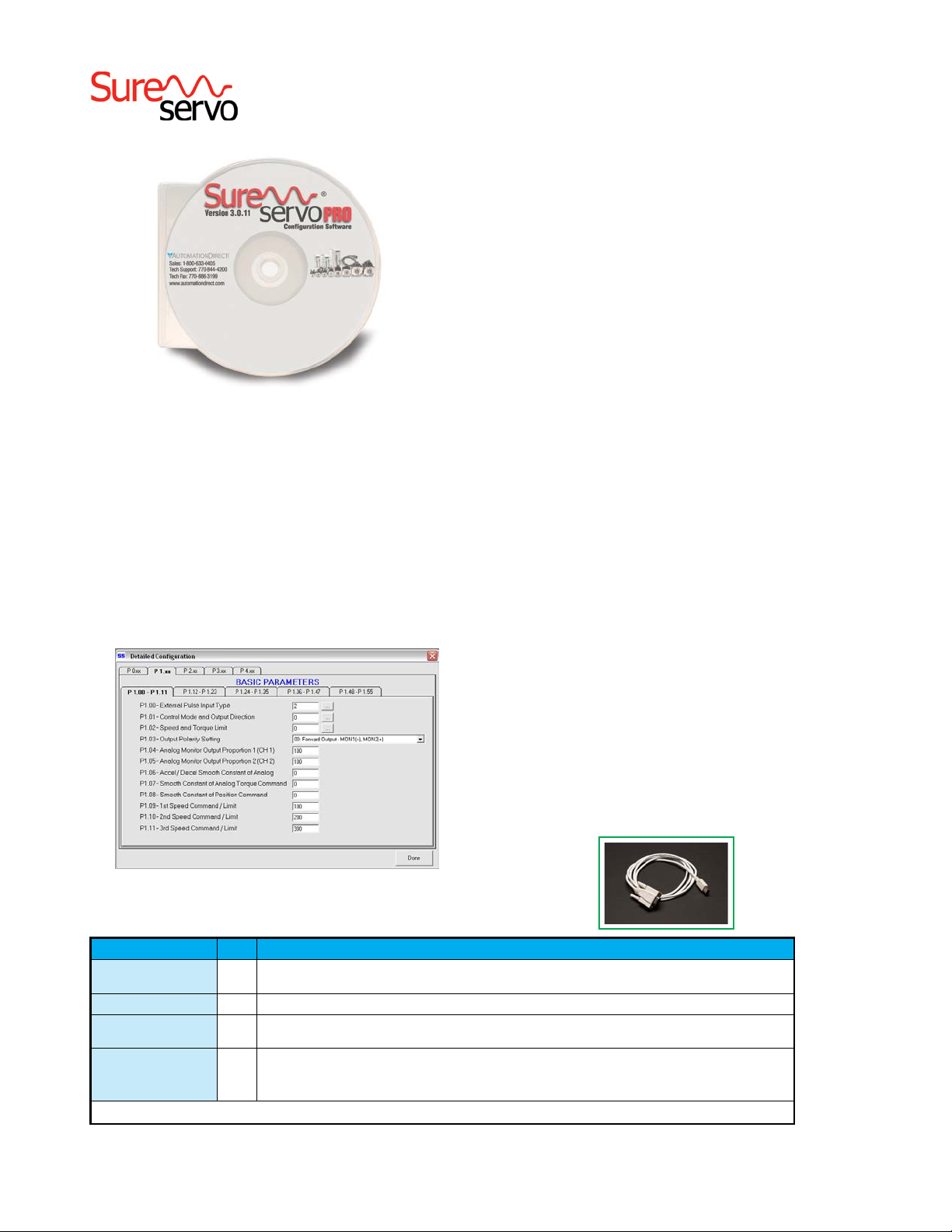
AC Servo System Software
Parameter views
The SureServo Pro configuration tool logically organizes over
165 servo drive parameters into five tabbed groups. Each
parameter has a factory default that usually allows the servo to
run “out-of-the-box”.
The parameters can be easily changed with available options
or setting ranges displayed. Tuning modes and parameters
can also be changed using SureServo Pro. After the parameters have been defined, the complete setup can be stored
and archived. Drive configurations can be uploaded, edited,
saved, and downloaded as often as necessary.
For the latest prices, please check AutomationDirect.com.
SureServo Pro configuration software
SureServo Pro is an optional free downloadable configuration
software package for the SureServo drives. With SureServo Pro
installed, the personal computer may be directly connected to
the servo drive’s serial port via the PC’s RS-232 serial port*.
A six-foot configuration cable (SVC-PCCFG-CBL, $19.50) is
available to make the connection between the drive serial port
and PC DB-9 serial port simple.
*Note: Use our USB-RS232 converter cable in conjunction with the SVC-PCCFGCBL cable on PCs having only USB ports.
Features
• • Quick Start - The basic setup when you have limited time and just
want to get up and running ASAP.
• • Maintenance keypad allows the user to operate the servo system
from the PC. This is a great aid during start-up to allow the servo to
perform some basic motion and to check the I/O.
• • Detailed - The complete setup for all the drive parameters
• • Tune and check the servo response live using the scope feature.
• • Upload and download the drive setup. Save the drive setup as a
file for future use.
• • Edit the drive setup
• • View all drive faults
• • Trend drive variables in real time
Parameter View Example Screen - Basic Parameters
SureServo Software and Configuration Cables
Product Price Description
SureServo Pro configuration software for use with all SureServo servo systems.
SV-PRO
SV-PRO
SVC-PCCFG-CBL
SVC-485CFG-CBL-2
* Refer to the ZIPLinks Wiring Solutions section for complete information regarding ZIPLink cable SVC-485CFG-CBL-2.
Free
FREE download from www.sureservo.com or www.automationdirect.com websites.
$9.50 CD with SureServo Pro configuration software
Six-foot RS-232 communications cable; connects servo drive serial port to PC DB-9 serial port.
$24.50
For PCs having only USB ports, use our USB-RS232 converter cable in conjunction with the SVC-PCCFG-CBL cable.
ZIPLink SureServo amplifier configuration cable, 6-pin IEEE 1394 connector to RJ45 connector, shielded, twisted pair,
2.0 meter (6.6 ft.) length.
$12.00
Use this cable in conjunction with our USB-485M serial adapter to connect any SureServo amplifier to a PC. Eliminates the need to
reprogram networked servo drives from RS485 to RS232 when connecting to a PC.
www.automationdirect.com
Motion Control
tMNC-174
Page 10

®
1-800-633-0405
Precision Servo Gearboxes
SureGear® Servo Gearbox Overview
PGA In-line Series
The SureGear PGA series of high-precision servo gear reducers
is an excellent choice for applications that require good accuracy and reliability at an exceptional value. This in-line planetary
gear reducer has a thread-in mounting style, along with a level of
precision and torque capacity that is best in its class. Offered in a concentric
shaft design with a maximum seven arc-min backlash rating, the SureGear
PGA series is an accurate, high-performance, and cost effective solution for
any OEM.
The machining quality of the SureGear PGA helical planetary
gears provides a very quiet and more efficient reducer than other
competitive products that are similarly priced. The SureGear PGA
series easily mates to SureServo motors, and is the perfect solution for applications such as gantries, injection-molding machines,
pick-and-place automation, and linear slides.
PGB Right-angle Series
The SureGear PGB series of high-precision right-angle servo gear reducers
is an excellent choice for applications that require a more compact footprint.
The PGB right-angle planetary gear reducers offer similar technical specifications to the PGA series in-line gear reducers, and provides the customer with
an excellent solution when space and clearance requirements are limited.
Offered with a six arc-min backlash rating for 2-stage and nine arc-min
backlash for 3-stage, the SureGear PGB series performs to OEMs’
demanding expectations.
PGD Hub Style In-line Series
The SureGear PGD series sets a new standard in applications requiring
extremely high-torque ratings and rigidity. The compact design and hubstyle output is ideal for equipment that requires high-speed, high-precision
indexing movement. The remarkable torsion stiffness and the low backlash
of the planetary gearing combine to provide outstanding positioning accuracy.
With a backlash rating less than 3 arc-minutes and exceptional torque
handling capabilities, the PGD series offers a high performance robust
planetary solution for OEM customers. The PGD reducer is often used
for larger indexing applications and dial tables commonly found in
packaging and filling equipment and assembly automation systems.
For the latest prices, please check AutomationDirect.com.
SureGear
PGA Gearbox
SureGear PGB Gearbox
SureGear
Hub Style PGD Gearbox
Features
• • Thread-in mounting style
• • Best-in-class backlash
• • Four gear ratios available (5:1, 10:1, 15:1, 25:1), Two additional for PGD
models (35:1 and 50:1)
• • Mounting hardware included for attaching to SureServo motors
• • Helical-cut planetary gears for quiet operation and reduced vibration
• • Right-angle reducer utilizes a spiral bevel gear; motor can be located at a
90° position from the reducer, providing a more compact footprint
• • Uncaged needle roller bearings for high rigidity and torque
• • Adapter bushing connection for simple and effective attachment to most
servo motors
• • High-viscosity, anti-separation grease does not migrate away from the
gears; no leakage through the seal
• • Maintenance free: No need to replace the grease for the life of the unit
• • At nominal speed, service life is 20,000 hours
• • Can be positioned in any orientation
• • IP55 environmental rating
• • 5-year warranty
www.automationdirect.com
SureGear
2-Stage Cutaway View
Applications
• • Gantries
• • Injection-molding machines
• • Pick-and-place automation
• • Linear slides
• • Packaging machines
• • Conveyors
Motion Control
tMNC-188
Page 11
®
1-800-633-0405
For the latest prices, please check AutomationDirect.com.
Precision Servo Gearboxes
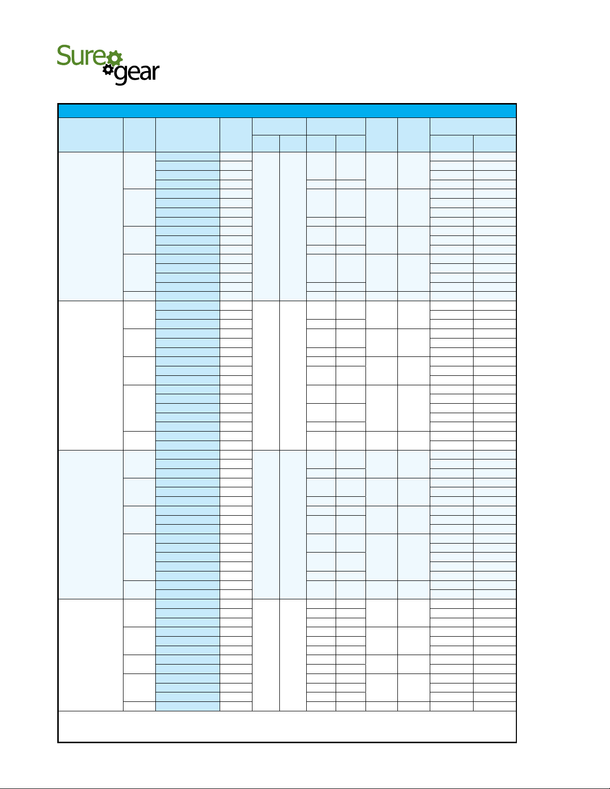
SureGear® Servo Gearbox Selection
SureGear® Servo Gearbox Selection
Sure
Servo
Motor
SVL-201(B)
SVL-202(B)
SVL-204(B)
SVL-207(B)
* Available load inertia is calculated based on servo motor inertia using the formula: Available Inertia = (5 x Motor Inertia – Gearbox Inertia) x (Gear Ratio)2
A 5:1 inertia mismatch is a good target for design purposes. Systems with lower or higher mismatch may be possible, depending on operating conditions.
** This gearbox is NOT a suitable choice at a 5:1 mismatch. If inertia balancing is a selection criteria for your end use, please use a mismatch of 8:1 to 10:1.
Gear
Ratio
5:1
10:1
15:1
25:1
50:1
5:1
10:1
15:1
25:1
50:1
5:1
10:1
15:1
25:1
50:1
5:1
10:1
15:1
25:1
50:1
SureGear
Gearbox
PGD047-05A1
PGA050-05A1
PGA070-05A1
PGB070-05A1
PGD047-10A1
PGA050-10A1
PGA070-10A1
PGB070-10A1
PGA050-15A1
PGA070-15A1
PGB070-15A1
PGD047-25A1
PGA050-25A1
PGA070-25A1
PGB070-25A1
PGD064-50A1
PGD064-05A2
PGA070-05A2
PGB070-05A2
PGD064-10A2
PGA070-10A2
PGB070-10A2
PGA070-15A2
PGB070-15A2
PGB090-15A2
PGD064-25A2
PGA070-25A2
PGB070-25A2
PGB090-25A2
PGD090-25A2
PGD090-50A2
PGD110-50A2
PGD064-05A2
PGA070-05A2
PGB070-05A2
PGD064-10A2
PGA070-10A2
PGB070-10A2
PGA070-15A2
PGB070-15A2
PGB090-15A2
PGD064-25A2
PGA070-25A2
PGB070-25A2
PGB090-25A2
PGD090-25A2
PGD090-50A2
PGD110-50A2
PGA070-05A3
PGB090-05A3
PGD090-05A3
PGA090-10A3
PGB090-10A3
PGD090-10A3
PGA090-15A3
PGB090-15A3
PGA090-25A3
PGB090-25A3
PGD110-25A3
PGD110-50A3
Motor Nominal
Frame
Output Torque
Size
(mm)
N·m lb·in N·m lb·in kg·cm
47
50 2.85 0.003
70 1.83 0.002
70 1.49 13.16 -2.50** -0.002**
47
50 12.00 0.011
70 9.40 0.008
70 2.98 26.32 -8.00** -0.007**
0.32 2.83
50
70 21.38 0.019
70 4.22 37.36 17.33 0.015
47
50 72.50 0.064
70 60.63 0.054
70 7.04 62.26 49.38 0.044
64 14.40 127.35 60 100 252.50 0.223
64
70 20.58 0.018
70 2.98 26.51 16.25 0.014
64
70 84.40 0.075
70 5.95 53.01 67.00 0.059
70 8.64 76.95
70
0.64 5.7
90 126.00 0.112
64
70 529.38 0.468
70
90 362.50 0.321
90 14.40 128.25 481.25 0.426
90
110 1250.00 1.106
64
70 40.58 0.036
70 5.91 52.08 36.25 0.032
64
70 164.40 0.145
70 11.81 104.16 147.00 0.130
70 17.15 151.20
70
1.27 11.2
90 306.00 0.271
64
70 1029.38 0.911
70
90 862.50 0.763
90 28.58 252.00 981.25 0.868
90
110 3250.00 2.876
70
90 11.11 98.58 90.00 0.080
90 11.35 100.70 120.50 0.107
90 22.71 201.40
90 22.23 197.16 371.00 0.328
90 22.71 201.40 507.00 0.449
2.39 21.2
90 32.27 286.20
90 31.55 279.84 1138.50 1.008
90 53.78 477.00
90 52.58 466.40 3175.00 2.810
110 53.78 477.00 2937.50 2.600
110 107.55 954.00 60 100 12500.00 11.063
Combo Nominal
Output Torque
1.52 13.44
3.04 26.89
4.32 38.21
7.20 63.68
3.04 27.08
6.08 54.15
8.45 75.24
14.40 128.25
14.08 125.40
28.80 256.50 60 100
6.03 53.20
12.07 106.40
16.76 147.84
28.58 252.00
27.94 246.40
57.15 504.00 60 100
11.35 100.70
Nominal
Output
Speed
( rpm )
600 1,000
300 500
200 333
120 200
600 1,000
300 500
200 333
120 200
600 1,000
300 500
200 333
120 200
600 1000
300 500
200 333
120 200
Max
Output
Speed
( rpm )
Available Load Inertia
@ 5:1 Mismatch *
2
2.68 0.002
11.80 0.010
25.88 0.023
72.50 0.064
20.00 0.018
83.80 0.074
190.13 0.168
186.08 0.165
528.75 0.468
518.13 0.459
2000.00 1.770
40.00 0.035
163.80 0.145
370.13 0.328
366.08 0.324
1028.75 0.910
1018.13 0.901
4000.00 3.540
133.08 0.118
511.00 0.452
1185.75 1.049
3300.00 2.921
lb·in·s
2
www.automationdirect.com
Motion Control
tMNC-189
Page 12

®
1-800-633-0405
Precision Servo Gearboxes
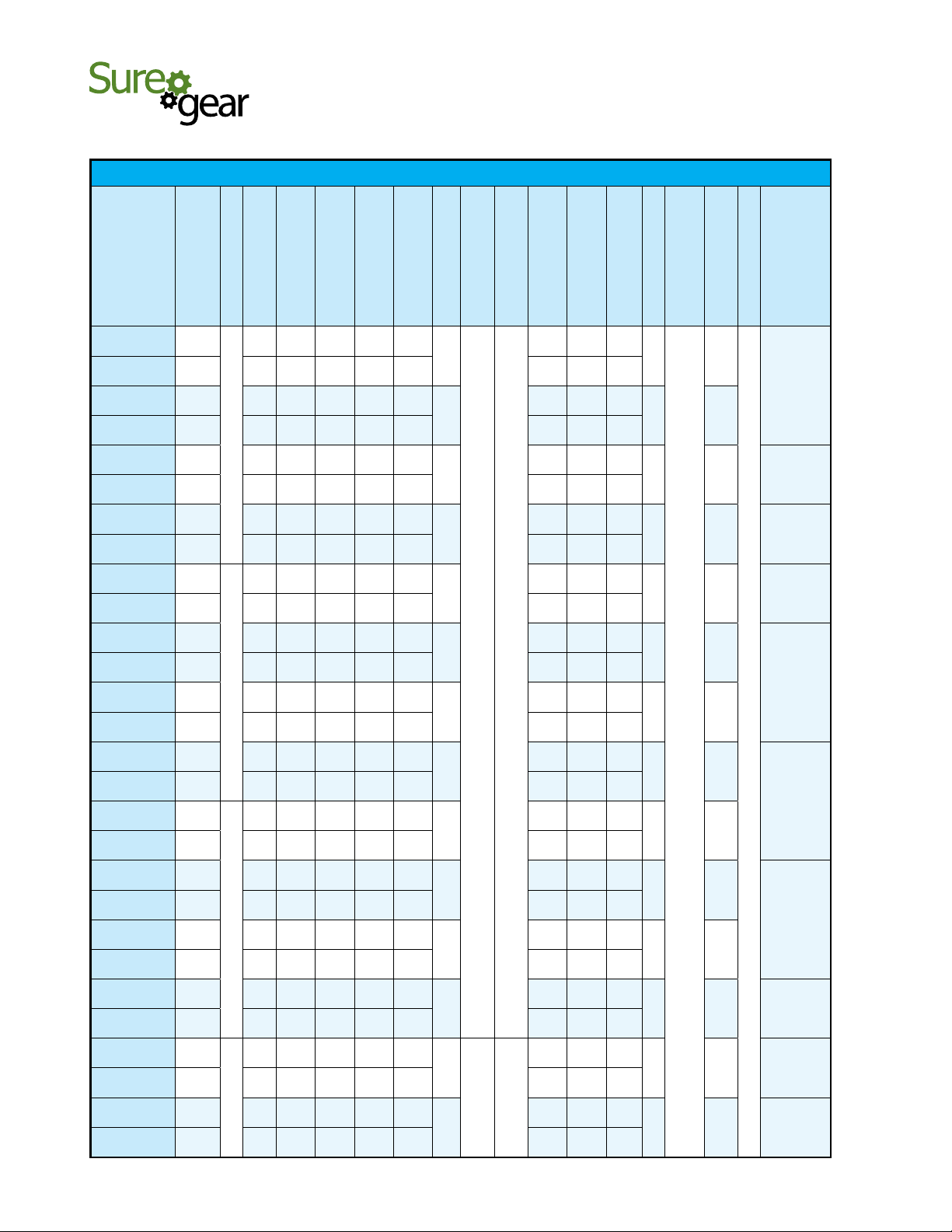
SureGear® Servo Gearbox Selection (continued)
For the latest prices, please check AutomationDirect.com.
Sure
Servo
Motor
SVL-210(B)
SVM-210(B)
SVM-220(B)
SVM-230(B)
Gear
Ratio
5:1
10:1
15:1
25:1
50:1
5:1
10:1
15:1
25:1
35:1
5:1
10:1
15:1
25:1
5:1
10:1
15:1
25:1
SureGear
Gearbox
PGA090-05A4
PGB090-05A4
PGD090-05A4
PGA090-10A4
PGB090-10A4
PGD090-10A4
PGA120-15A4
PGB120-15A4
PGD110-25A4
PGA120-25A4
PGB120-25A4
PGD110-50A4
PGA090-05A5
PGD090-05A5
PGB120-05A5
PGA090-10A5
PGD110-10A5
PGB120-10A5
PGA120-15A5
PGB120-15A5
PGD110-25A5
PGA120-25A5
PGB120-25A5
PGD110-35A5
PGD110-05A6
PGA120-05A6
PGB120-05A6
PGB155-05A6
PGD110-10A6
PGA120-10A6
PGB120-10A6
PGB155-10A6
PGA155-15A6
PGB155-15A6
PGA155-25A6
PGB155-25A6
PGD110-05A6
PGA120-05A6
PGB120-05A6
PGD110-10A6
PGA120-10A6
PGB120-10A6
PGB155-10A6
PGA155-15A6
PGB155-15A6
PGA155-25A6
PGB155-25A6
SureGear® Servo Gearbox Selection
Motor Nominal
Frame
Output Torque
Size
(mm)
N·m lb·in N·m lb·in kg·cm
90
90 15.35 135.78 280.00 0.248
90 15.68 138.70 313.00 0.277
90 31.45 277.40
90 30.69 271.56 1131.00 1.001
90 31.35 277.40 1267.00 1.121
120 44.55 394.20
120 43.56 385.44 2418.75 2.141
110
120 7887.50 6.980
120 72.60 642.40 6762.50 5.985
110 148.50 1314.00 60 100 31500.00 27.878
120 22.32 197.63 622.00 0.550
110 2957.00 2.617
120 44.64 395.25 2544.00 2.251
120 64.80 573.75
120 63.36 561.00 6221.25 5.506
110
120 18450.00 16.328
120 105.60 935.00 17325.00 15.333
110 151.20 1338.75 86 143 35770.00 31.656
110
120 5372.50 4.755
120
155 4989.75 4.416
110
120 21555.00 19.076
120
155 20184.00 17.863
155 126.90 1123.20
155 124.08 1098.24 47272.50 41.836
155 211.50 1872.00
155 206.80 1830.40 131468.75 116.350
110
120 5372.50 4.755
120 66.50 588.69 5287.00 4.679
110
120 21555.00 19.076
120
155 20184.00 17.863
155 193.05 1709.10
155 188.76 1671.12 47272.50 41.836
155 321.75 2848.50
155 314.60 2785.20 131468.75 116.350
3.3 29.2
90
90 735.50 0.651
90
4.8 42.5
9.4 83.2
14.3 12.6
Combo Nominal
Output Torque
15.68 138.70
74.25 657.00
22.80 201.88
45.60 403.75
108.00 956.25
44.65 395.20
43.71 386.88
89.30 790.40
87.42 773.76
67.93 601.35
135.85 1202.70
132.99 1177.38
Nominal
Output
Speed
( rpm )
600 1000
300 500
200 333
120 200
600 1000
300 500
200 333
120 200
600 1000
300 500
200 333
120 200
600 1000
300 500
200 333
120 200
Max
Output
Speed
( rpm )
Available Load Inertia
@ 5:1 Mismatch *
2
315.00 0.279
1271.00 1.125
2828.25 2.503
7687.50 6.803
737.50 0.653
2961.00 2.620
6630.75 58.68
18250.00 16.151
5355.00 4.739
5287.00 4.679
21540.00 19.063
21204.00 18.766
48420.00 42.852
134625.00 119.143
5355.00 4.739
21540.00 19.063
21204.00 18.766
48420.00 42.852
134625.00 119.143
lb·in·s
2
* Available load inertia is calculated based on servo motor inertia using the formula: Available Inertia = (5 x Motor Inertia – Gearbox Inertia) x (Gear Ratio)2
A 5:1 inertia mismatch is a good target for design purposes. Systems with lower or higher mismatch may be possible, depending on operating conditions.
www.automationdirect.com
Motion Control
tMNC-190
Page 13

®
1-800-633-0405
Precision Servo Gearboxes
Pricing & Specifications – In-Line Shaft PGA Series
SureGear® Precision Servo Gearboxes – In-Line Shaft PGA Series
For the latest prices, please check AutomationDirect.com.
)
2
Part Number
PGA050-05A1
PGA050-10A1
PGA050-15A1
PGA050-25A1
PGA070-05A1
PGA070-10A1
PGA070-15A1
PGA070-25A1
PGA070-05A2
PGA070-10A2
PGA070-15A2
PGA070-25A2
PGA070-05A3
PGA090-10A3
PGA090-15A3
PGA090-25A3
PGA090-05A4
PGA090-10A4
PGA090-05A5
PGA090-10A5
PGA120-15A4
PGA120-25A4
PGA120-15A5
PGA120-25A5
PGA120-05A6
PGA120-10A6
PGA155-10A6
PGA155-15A6
PGA155-25A6
Price
Ratio
Frame Size (mm)
$430.00
$453.00 10:1 single
$621.00 15:1 double
$621.00 25:1 double
$430.00
$453.00 10:1 single
$621.00 15:1 double
$621.00 25:1 double
$469.00 5:1 single
$469.00 10:1 single
$643.00 15:1 double
$643.00 25:1 double
$469.00 5:1 single
$556.00
$734.00 15:1 double
$734.00 25:1 double
$555.00 5:1 single
$555.00 10:1 single
$555.00 5:1 single
$555.00 10:1 single
$922.00
$922.00 25:1 double
$922.00 15:1 double
$922.00 25:1 double
$735.00 5:1 single
$735.00 10:1 single
$908.00
$1,236.00 15:1 double
$1,236.00 25:1 double
5:1 single
50
5:1 single
70
10:1 single
90
15:1 double
120
10:1 single
155
Reduction
Nominal Output
Torque ( N·m [lb·in] )
9
[80]
[159]
6
[53]
[106]
6
[53]
[106]
9
[80]
[159]
27
[239]
[443]
18
[159]
[310]
18
[159]
[310]
27
[239]
[443]
27
[239]
[443]
18
[159]
[310]
18
[159]
[310]
27
[239]
[443]
27
[239]
[443]
50
[443]
[708]
50
[443]
[708]
75
[664]
[1106]
75
[664]
[1106]
50
[443]
[708]
75
[664]
[1106]
50
[443]
[708]
120
[1062]
[1991]
180
[1593]
[2921]
120
[1062]
[1991]
180
[1593]
[2921]
180
[1593]
[2921]
120
[1062]
[1991]
240
[2124]
[4160]
240
[2124]
[4160]
360
[3186]
[6196]
Emergency Stop
Max. Acceleration
Torque ( N·m [lb·in] )
18
12
12
18
50
35
35
50
50
35
35
50
50
80
[1770]
80
[1770]
125
[2213]
125
[2213]
80
[1770]
125
[2213]
80
[1770]
225
[4425]
330
[5532]
225
[4425]
330
[5532]
330
[5532]
225
[4425]
470
[8851]
470
[8851]
700
[11063]
Backlash (arc-min)
Torque ( N·m [lb·in] )
35
[310]
5
30
[266]
30
[266]
7
35
[310]
100
[885]
80
[708]
80
[708]
100
[885]
100
[885]
80
[708]
80
[708]
100
[885]
100
[885]
200
200
250
250
5
200
250
200
500
625
500
625
625
500
1000
1000
1250
Speed (rpm)
Nominal Input
4000 8000
3000 6000
2000 4000
Max. Input
Speed (rpm)
Allowable Radial
290
[65]
360
[81]
410
[92]
490
[110]
510
[115]
640
[144]
740
[166]
870
[196]
510
[115]
640
[144]
740
[166]
870
[196]
510
[115]
1200
[270]
1400
[315]
1600
[360]
960
[216]
1200
[270]
960
[216]
1200
[270]
2300
[517]
2700
[607]
2300
[517]
2700
[607]
1600
[360]
2000
[450]
4700
[1057]
5400
[1214]
6400
[1439]
Load ( N [lb] )
Load ( N [lb] )
Allowable Thrust
Moment of Inertia
330
0.036
[74]
450
0.030
[101]
540
0.035
[121]
640
0.034
[144]
390
0.077
[88]
530
0.056
[119]
630
0.055
[142]
790
0.053
[178]
390
0.160
[88]
530
0.140
[119]
630
0.140
[142]
790
0.130
[178]
390
0.360
[88]
1600
0.750
[360]
1900
0.720
[427]
2200
0.710
[495]
1200
2.900
[270]
1600
2.800
[360]
1200
2.900
[270]
1600
2.800
[360]
3000
2.800
[674]
3700
2.800
[832]
3000
2.800
[674]
3700
2.800
[832]
1900
11.000
[427]
2500
11.000
[562]
4100
11.000 95
[922]
4900
11.000
[1102]
6100
11.000
[1371]
(kg·cm
Efficiency (%)
95
90
95
90
95
90
95
90 °C
[194 °F]
90
95
90
95
90
Temperature
Max. Housing
Approx Weight
0.7
[1.5]
0.8
[1.8]
1.5
[3.3]
1.7
[3.7]
1.5
[3.3]
1.7
[3.7]
1.5
[3.3]
3.5
[7.7]
4.0
[8.8]
3.5
[7.7]
3.5
[7.7]
8.7
[19.2]
8.7
[19.2]
7.8
[17.2]
16
[35.3]
18
[40.0]
Rating
( kg [lb] )
Environmental
IP55
Servo Motor
Fits SureServo
SVL-201(B)
SVL-202(B)
SVL-204(B)
SVL-207(B)
SVL-210(B)
SVM-210(B)
SVL-210(B)
SVM-210(B)
SVM-220(B)
SVM-230(B)
www.automationdirect.com
Motion Control
tMNC-191
Page 14

®
1-800-633-0405
For the latest prices, please check AutomationDirect.com.
Precision Servo Gearboxes
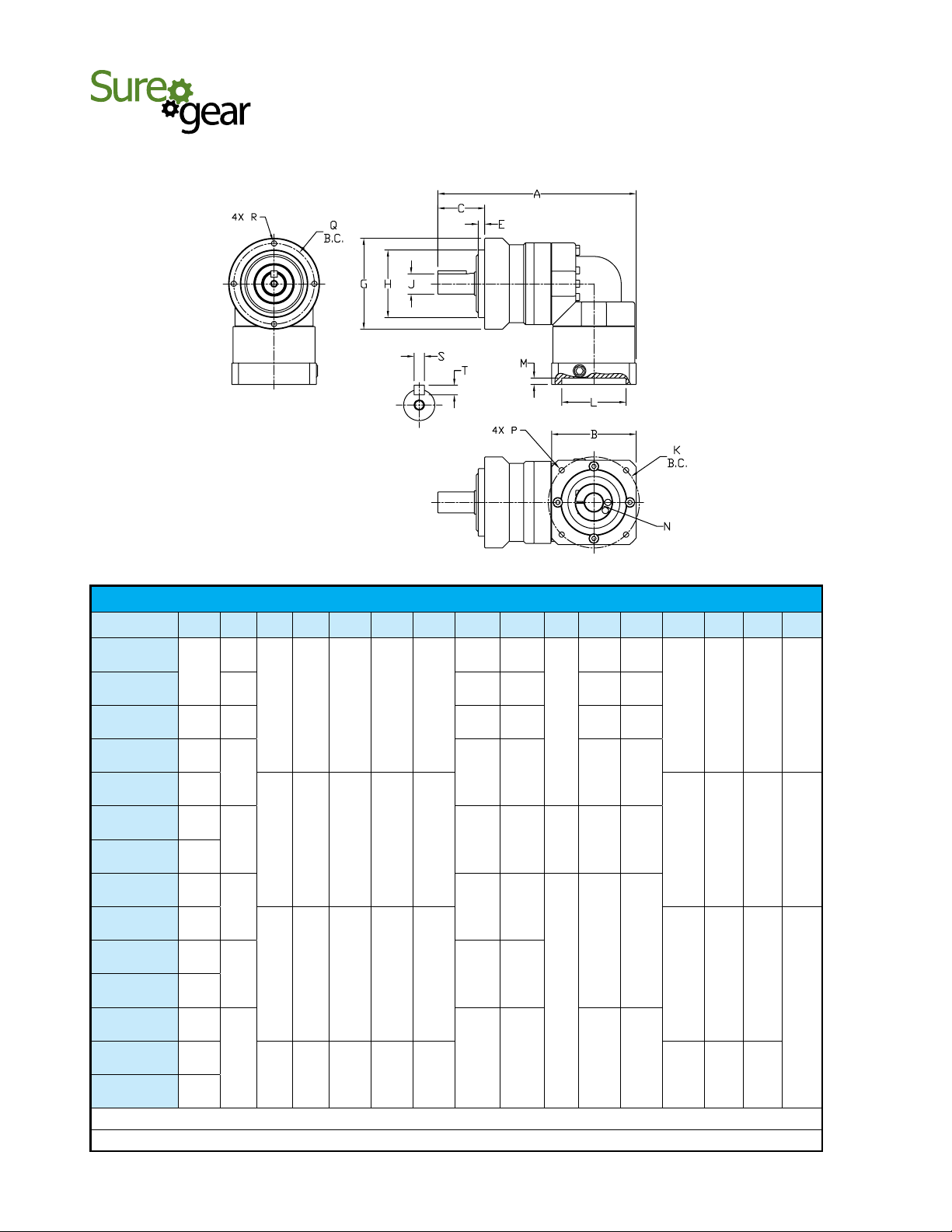
Dimensions – In-Line Shaft PGA Series
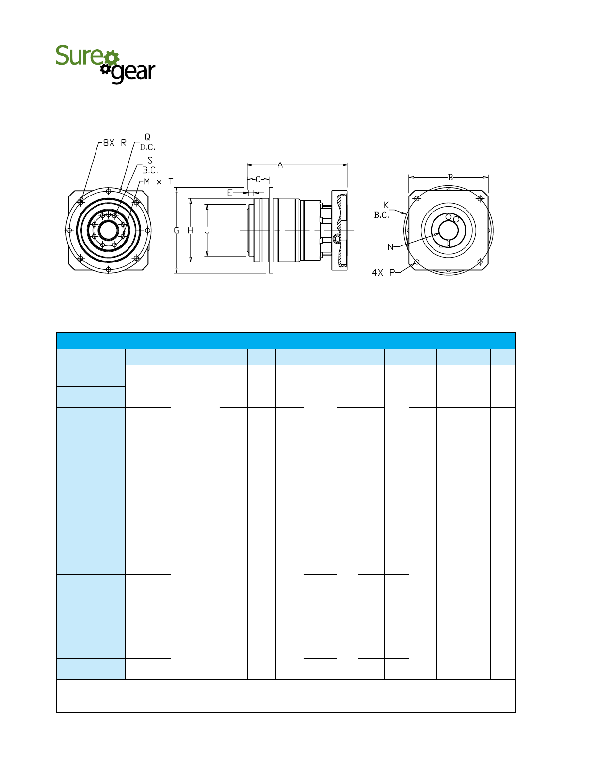
SureGear PGA Series In-Line Shaft Gearboxes Dimension Drawing
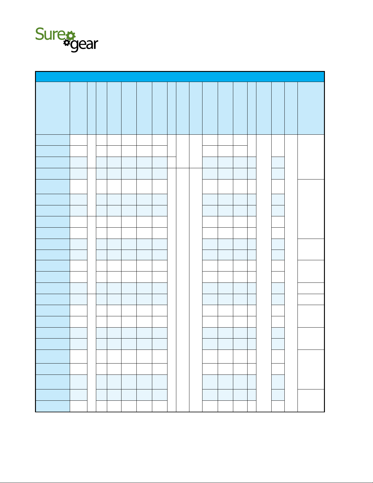
SureGear® Precision Servo Gearbox Dimensions – In-Line Shaft PGA Series ( dimensions = mm [in] )
Part Number A B C E G H J K L M N P Q R S T
88.5
42.0
24.5
4.0
Ø50.0
Ø35.0
Ø12.0
Ø46.0
Ø30.0
5.0
Ø8.0
M4-
PGA050-05A1
PGA050-10A1
PGA050-15A1
PGA050-25A1
PGA070-05A1
PGA070-10A1
PGA070-05A2
PGA070-10A2
PGA070-05A3
PGA070-15A1
PGA070-25A1
PGA070-15A2
PGA070-25A2
PGA090-10A3
PGA090-05A4
PGA090-10A4
PGA090-05A5
PGA090-10A5
PGA090-15A3
PGA090-25A3
PGA120-05A6
PGA120-10A6
PGA120-15A4
PGA120-25A4
PGA120-15A5
PGA120-25A5
PGA155-10A6
PGA155-15A6
PGA155-25A6
* Dimension with supplied bushing
NOTE: See our website: www.AutomationDirect.com for complete engineering drawings.
[3.48]
105.0
[4.13]
112.0
[4.41]
115.0
[4.53]
130.0
[5.12]
131.0
[5.16]
136.0
[5.35]
153.0
[6.02]
170.0
[6.69]
165.0
[6.50]
175.0
[6.89]
225.0
[8.86]
231.5
[9.11]
231.5
[9.11]
264.0
[10.39]
298.5
[11.75]
[1.65]
42.0
[1.65]
52.0
[2.05]
65.0
[2.56]
80.0
[3.15]
52.0
[2.05]
65.0
[2.56]
80.0
[3.15]
100.0
[3.94]
130.0
[5.12]
80.0
[3.15]
180.0
[7.09]
100.0
[3.94]
130.0
[5.12]
180.0
[7.09]
180.0
[7.09]
[0.96]
24.5
[0.96]
36.0
[1.42]
36.0
[1.42]
36.0
[1.42]
36.0
[1.42]
36.0
[1.42]
46.0
[1.81]
46.0
[1.81]
46.0
[1.81]
46.0
[1.81]
70.0
[2.76]
70.0
[2.76]
70.0
[2.76]
97.0
[3.82]
97.0
[3.82]
[0.16]
4.0
[0.16]
5.0
[0.20]
5.0
[0.20]
5.0
[0.20]
5.0
[0.20]
5.0
[0.20]
7.0
[0.28]
7.0
[0.28]
7.0
[0.28]
7.0
[0.28]
9.0
[0.35]
9.0
[0.35]
9.0
[0.35]
12.0
[0.47]
12.0
[0.47]
[Ø1.97]
Ø50.0
[Ø1.97]
Ø70.0
[Ø2.76]
Ø70.0
[Ø2.76]
Ø70.0
[Ø2.76]
Ø70.0
[Ø2.76]
Ø70.0
[Ø2.76]
Ø90.0
[Ø3.54]
Ø90.0
[Ø3.54]
Ø90.0
[Ø3.54]
Ø90.0
[Ø3.54]
Ø120.0
[Ø4.72]
Ø120.0
[Ø4.72]
Ø120.0
[Ø4.72]
Ø155.0
[Ø6.10]
Ø155.0
[Ø6.10]
[Ø1.38]
Ø35.0
[Ø1.38]
Ø52.0
[Ø2.05]
Ø52.0
[Ø2.05]
Ø52.0
[Ø2.05]
Ø52.0
[Ø2.05]
Ø52.0
[Ø2.05]
Ø68.0
[Ø2.68]
Ø68.0
[Ø2.68]
Ø68.0
[Ø2.68]
Ø68.0
[Ø2.68]
Ø90.0
[Ø3.54]
Ø90.0
[Ø3.54]
Ø90.0
[Ø3.54]
Ø120.0
[Ø4.72]
Ø120.0
[Ø4.72]
[Ø0.47]
Ø12.0
[Ø0.47]
Ø16.0
[Ø0.63]
Ø16.0
[Ø0.63]
Ø16.0
[Ø0.63]
Ø16.0
[Ø0.63]
Ø16.0
[Ø0.63]
Ø22.0
[Ø0.87]
Ø22.0
[Ø0.87]
Ø22.0
[Ø0.87]
Ø22.0
[Ø0.87]
Ø32.0
[Ø1.26]
Ø32.0
[Ø1.26]
Ø32.0
[Ø1.26]
Ø40.0
[Ø1.57]
Ø40.0
[Ø1.57]
[Ø1.81]
Ø46.0
[Ø1.81]
Ø46.0
[Ø1.81]
Ø70.0
[Ø2.76]
Ø90.0
[Ø3.54]
Ø46.0
[Ø1.81]
Ø70.0
[Ø2.76]
Ø90.0
[Ø3.54]
Ø115.0
[Ø4.53]
Ø145.0
[Ø5.71]
Ø90.0
[Ø3.54]
Ø200.0
[Ø7.87]
Ø115.0
[Ø4.53]
Ø145.0
[Ø5.71]
Ø200.0
[Ø7.87]
Ø200.0
[Ø7.87]
[Ø1.18]
Ø30.0
[Ø1.18]
Ø30.0
[Ø1.18]
Ø50.0
[Ø1.97]
Ø70.0
[Ø2.76]
Ø30.0
[Ø1.18]
Ø50.0
[Ø1.97]
Ø70.0
[Ø2.76]
Ø95.0
[Ø3.74]
Ø110.0
[Ø4.33]
Ø70.0
[Ø2.76]
Ø114.0
[Ø4.49]
Ø95.0
[Ø3.74]
Ø110.0
[Ø4.33]
Ø114.0
[Ø4.49]
Ø114.0
[Ø4.49]
[0.20]
5.0
[0.20]
5.0
[0.20]
5.0
[0.20]
6.0
[0.24]
5.0
[0.20]
5.0
[0.20]
6.0
[0.24]
8.0
[0.31]
8.0
[0.31]
6.0
[0.24]
8.0
[0.31]
8.0
[0.31]
8.0
[0.31]
8.0
[0.31]
8.0
[0.31]
[Ø0.31]
Ø8.0
[Ø0.31]
Ø8.0
[Ø0.31]
Ø14.0
[Ø0.55]
Ø19.0
[Ø0.75]
Ø8.0
[Ø0.31]
Ø14.0
[Ø0.55]
Ø19.0
[Ø0.75]
Ø22.0 *
[Ø0.87]
Ø22.0 *
[Ø0.87]
Ø19.0
[Ø0.75]
Ø35.0 *
[Ø1.38]
Ø22.0 *
[Ø0.87]
Ø22.0 *
[Ø0.87]
Ø35.0 *
[Ø1.38]
Ø35.0 *
[Ø1.38]
0.7x9
M4-
0.7x9
M4-
0.7x9
M5-
0.8x11
M6-
1.0x13
M4-
0.7x9
M5-
0.8x11
M6-
1.0x13
M8-
1.25x17
M8-
1.25x17
M6-
1.0x13
M12-
1.75x25
M8-
1.25x17
M8-
1.25x17
M12-
1.75x25
M12-
1.75x25
Ø44.0
[Ø1.73]
Ø44.0
[Ø1.73]
Ø62.0
[Ø2.44]
Ø62.0
[Ø2.44]
Ø62.0
[Ø2.44]
Ø62.0
[Ø2.44]
Ø62.0
[Ø2.44]
Ø80.0
[Ø3.15]
Ø80.0
[Ø3.15]
Ø80.0
[Ø3.15]
Ø80.0
[Ø3.15]
Ø108.0
[Ø4.25]
Ø108.0
[Ø4.25]
Ø108.0
[Ø4.25]
Ø140.0
[Ø5.51]
Ø140.0
[Ø5.51]
1.25x16
1.25x16
1.25x16
1.50x28
1.50x28
M4-
0.7x8
M4-
0.7x8
M5-
0.8x10
M5-
0.8x10
M5-
0.8x10
M5-
0.8x10
M5-
0.8x10
M6-
1.0x12
M6-
1.0x12
M6-
1.0x12
M6-
1.0x12
M8-
M8-
M8-
M10-
M10-
4.0
[0.16]
4.0
[0.16]
5.0
[0.20]
5.0
[0.20]
5.0
[0.20]
5.0
[0.20]
5.0
[0.20]
6.0
[0.24]
6.0
[0.24]
6.0
[0.24]
6.0
[0.24]
10.0
[0.39]
10.0
[0.39]
10.0
[0.39]
12.0
[0.47]
12.0
[0.47]
4.0
[0.16]
4.0
[0.16]
5.0
[0.20]
5.0
[0.20]
5.0
[0.20]
5.0
[0.20]
5.0
[0.20]
6.0
[0.24]
6.0
[0.24]
6.0
[0.24]
6.0
[0.24]
8.0
[0.31]
8.0
[0.31]
8.0
[0.31]
8.0
[0.31]
8.0
[0.31]
www.automationdirect.com
Motion Control
tMNC-192
Page 15
®
1-800-633-0405
Precision Servo Gearboxes
Pricing & Specifications – Right-Angle Shaft PGB Series
SureGear® Precision Servo Gearboxes – Right-Angle Shaft PGB Series
For the latest prices, please check AutomationDirect.com.
)
2
Part Number
PGB070-05A1
PGB070-10A1
PGB070-15A1
PGB070-25A1
PGB070-05A2
PGB070-10A2
PGB070-15A2
PGB070-25A2
PGB090-15A2
PGB090-25A2
PGB090-05A3
PGB090-10A3
PGB090-15A3
PGB090-25A3
PGB090-05A4
PGB090-10A4
PGB120-15A4
PGB120-25A4
PGB120-05A5
PGB120-10A5
PGB120-15A5
PGB120-25A5
PGB120-05A6
PGB120-10A6
PGB155-15A6
PGB155-25A6
PGB155-05A6
PGB155-10A6
Price
Ratio
Frame Size (mm)
$729.00
$729.00 10:1 double
$922.00 15:1 triple
$922.00 25:1 triple
$729.00 5:1 double
$729.00 10:1 double
$922.00 15:1 triple
$922.00 25:1 triple
$1,125.00
$1,125.00 25:1 triple
$862.00 5:1 double
$862.00 10:1 double
$1,125.00 15:1 triple
$1,125.00 25:1 triple
$862.00 5:1 double
$862.00 10:1 double
$1,398.00
$1,398.00 25:1 triple
$1,125.00 5:1 double
$1,125.00 10:1 double
$1,398.00 15:1 triple
$1,398.00 25:1 triple
$1,125.00 5:1 double
$1,125.00 10:1 double
$1,637.00
$1,637.00 25:1 triple
$1,295.00 5:1 double
$1,295.00 10:1 double
5:1 double
70
15:1 triple
90
15:1 triple
120
15:1 triple
155
Reduction
Nominal Output
Torque ( N·m [lb·in] )
22
[195]
16
[142]
16
[142]
24
[212]
22
[195]
16
[142]
16
[142]
24
[212]
45
[398]
65
[575]
65
[575]
45
[398]
45
[398]
65
[575]
65
[575]
45
[398]
110
[974]
150
[1328]
120
[1062]
110
[974]
110
[974]
150
[1328]
120
[1062]
110
[974]
200
[1770]
300
[2655]
200
[1770]
200
[1770]
Max. Acceleration
40
[354]
32
[283]
32
[283]
45
[398]
40
[354]
32
[283]
32
[283]
45
[398]
65
[575]
110
[974]
90
[797]
65
[575]
65
[575]
110
[974]
90
[797]
65
[575]
200
[1770]
300
[2655]
240
[2124]
200
[1770]
200
[1770]
300
[2655]
240
[2124]
200
[1770]
400
[3540]
600
[5310]
400
[3540]
400
[3540]
( N·m [lb·in] )
Torque ( N·m [lb·in] )
Emergency Stop Torque
80
[708]
65
[575]
65
[575]
90
[797]
80
[708]
65
[575]
65
[575]
90
[797]
170
[1505]
220
[1947]
220
[1947]
170
[1505]
170
[1505]
220
[1947]
220
[1947]
170
[1505]
450
[3983]
550
[4868]
500
[4425]
450
[3983]
450
[3983]
550
[4868]
500
[4425]
450
[3983]
750
[6638]
1100
[9736]
1100
[9736]
750
[6638]
Max. Input
Speed (rpm)
Speed (rpm)
Nominal Input
Backlash (arc-min)
6
9
6
9
9
6
3000 6000
9
6
9
6
9
6
9
2000 4000
6
Load ( N [lb] )
Allowable Radial
510
[115]
[88]
640
[144]
[119]
740
[166]
[142]
870
[196]
[178]
510
[115]
[88]
640
[144]
[119]
740
[166]
[142]
870
[196]
[178]
1400
1900
[314]
[427]
1600
2200
[360]
[495]
960
1200
[216]
[270]
1200
1600
[270]
[360]
1400
1900
[314]
[427]
1600
2200
[360]
[495]
960
1200
[216]
[270]
1200
1600
[270]
[360]
2300
3000
[517]
[674]
2700
3700
[607]
[832]
1600
1900
[360]
[427]
2000
2500
[450]
[562]
2300
3000
[517]
[674]
2700
3700
[607]
[832]
1600
1900
[360]
[427]
2000
2500
[450]
[562]
5400
4900
[1214]
[1102]
6400
6100
[1439]
[1371]
3800
3000
[854]
[674]
4700
4100
[1057]
[922]
Moment of
Load ( N [lb] )
Allowable Thrust
390
0.250
530
0.230
630
0.073
790
0.071
390
0.320
530
0.300
630
0.118
790
0.115
0.410
0.400
2.130
2.020
0.600
0.590
4.260
4.150
4.700
4.640
6.610
6.050
4.700
4.640
13.690
13.120
15.070
14.820
21.280
19.030
Temperature
Max. Housing
Efficiency (%)
Inertia (kg·cm
93
88
93
88
88
93
88
90 °C
[194 °F]
93
88
93
88
93
88
93
( kg [lb] )
Approx Weight
Environmental Rating
1.9
[4.2]
SVL-201(B)
1.7
[3.7]
1.9
[4.2]
1.7
[3.7]
4.3
[9.5]
4.9
[10.8]
4.3
[9.5]
4.9
[10.8]
10
[22]
10.2
[22.5]
10
[22]
10.2
[22.5]
20.4
[45.0]
19.8
[43.7]
SVL-202(B)
SVL-204(B)
SVL-202(B)
SVL-202(B)
SVL-204(B)
SVL-207(B)
IP55
SVL-210(B)
SVM-210(B)
SVM-220(B)
SVM-230(B)
SVM-220(B)
SVM-220(B)
SVM-230(B)
Servo Motor
Fits SureServo
www.automationdirect.com
Motion Control
tMNC-193
Page 16
®
1-800-633-0405
Precision Servo Gearboxes
Dimensions – Right-Angle Shaft PGB Series
For the latest prices, please check AutomationDirect.com.
SureGear PGB Series Right-Angle Shaft Gearboxes Dimension Drawing
SureGear® Precision Servo Gearbox Dimensions – Right-Angle Shaft PGA Series ( dimensions = mm [in] )
Part Number A B C E G H J K L M N P Q R S T
151.5
[5.96]
158.0
[6.22]
163.5
[6.44]
204.5
[8.05]
205.5
[8.09]
210.5
[8.29]
205.5
[8.09]
272.0
[10.71]
266.0
[10.47]
272.0
[10.71]
268.5
[10.57]
341.0
[13.43]
364.0
[14.33]
52.0
[2.05]
65.0
[2.56]
52.0
[2.05]
65.0
[2.56]
80.0
[3.15]
100.0
[3.94]
130.0
[5.12]
180.0
[7.09]
36.0
[1.42]
46.0
[1.81]
70.0
[2.76]
97.0
[3.82]
5.0
[0.20]
7.0
[0.28]
9.0
[0.35]
12.0
[0.47]
Ø70.0
[Ø2.76]
Ø90.0
[Ø3.54]
Ø120.0
[Ø4.72]
Ø155.0
[Ø6.10]
Ø52.0
[Ø2.05]
Ø68.0
[Ø2.68]
Ø90.0
[Ø3.54]
Ø120.0
[Ø4.72]
PGB070-05A1
PGB070-10A1
PGB070-05A2
PGB070-10A2
PGB070-15A1
PGB070-25A1
PGB070-15A2
PGB070-25A2
PGB090-15A2
PGB090-25A2
PGB090-05A3
PGB090-10A3
PGB090-15A3
PGB090-25A3
PGB090-05A4
PGB090-10A4
PGB120-15A4
PGB120-25A4
PGB120-05A5
PGB120-10A5
PGB120-15A5
PGB120-25A5
PGB120-05A6
PGB120-10A6
PGB155-05A6
PGB155-10A6
PGB155-15A6
PGB155-25A6
* Dimension with supplied bushing
NOTE: See our website: www.AutomationDirect.com for complete engineering drawings.
Ø16.0
[Ø0.63]
Ø22.0
[Ø0.87]
Ø32.0
[Ø1.26]
Ø40.0
[Ø1.57]
Ø46.0
[Ø1.81]
Ø70.0
[Ø2.76]
Ø46.0
[Ø1.81]
Ø70.0
[Ø2.76]
Ø90.0
[Ø3.54]
Ø115.0
[Ø4.53]
Ø145.0
[Ø5.71]
Ø200.0
[Ø7.87]
Ø30.0
[Ø1.18]
Ø50.0
[Ø1.97]
Ø30.0
[Ø1.18]
Ø50.0
[Ø1.97]
Ø70.0
[Ø2.76]
Ø95.0
[Ø3.74]
Ø110.0
[Ø4.33]
Ø114.0
[Ø4.50]
5.0
[0.20]
6.0
[0.24]
8.0
[0.31]
Ø8.0
[Ø0.31]
Ø14.0
[Ø0.55]
Ø8.0
[Ø0.31]
Ø14.0
[Ø0.55]
Ø19.0
[Ø0.75]
Ø22.0 *
[Ø0.87]
Ø35.0 *
[Ø1.38]
M4-
0.7x9
M5-
0.8x11
M4-
0.7x9
M5-
0.8x11
M6-
1.0x13
M8-
1.25x17
M12-
1.75x25
Ø62.0
[Ø2.44]
Ø80.0
[Ø3.15]
Ø108.0
[Ø4.25]
Ø140.0
[Ø5.51]
M5-
0.8x10
M6-
1.0x12
M8-
1.25x16
M10-
1.5x20
5.0
[0.20]
6.0
[0.24]
10.0
[0.39]
12.0
[0.47]
5.0
[0.20]
6.0
[0.24]
8.0
[0.31]
www.automationdirect.com
Motion Control
tMNC-194
Page 17
®
1-800-633-0405
Precision Servo Gearboxes
Pricing & Specifications – Hub Style In-Line PGD Series
SureGear® Precision Servo Gearboxes – Hub Style In-Line PGD Series
For the latest prices, please check AutomationDirect.com.
)
2
Part Number
PGD047-05A1
PGD047-10A1
PGD047-25A1
PGD064-50A1
PGD064-05A2
PGD064-10A2
PGD064-25A2
PGD090-25A2
PGD090-50A2
PGD090-05A3
PGD090-10A3
PGD090-05A4
PGD090-10A4
PGD090-05A5
PGD110-50A2
PGD110-25A3
PGD110-50A3
PGD110-25A4
PGD110-50A4
PGD110-10A5
PGD110-25A5
PGD110-35A5
PGD110-05A6
PGD110-10A6
Price
Ratio
Frame Size (mm)
$780.00
$780.00 10:1 single
$976.00 25:1 double
$1,181.00
$1,008.00 5:1 single
$1,008.00 10:1 single
$1,181.00 25:1 double
$1,354.00
$1,354.00 50:1 double
$1,181.00 5:1 single
$1,181.00 10:1 single
$1,181.00 5:1 single
$1,181.00 10:1 single
$1,181.00 5:1 single
$1,727.00
$1,727.00 25:1 double
$1,727.00 50:1 double
$1,727.00 25:1 double
$1,727.00 50:1 double
$1,468.00 10:1 single
$1,727.00 25:1 double
$1,727.00 35:1 double
$1,468.00 5:1 single
$1,468.00 10:1 single
5:1 single
47
50:1 double
64
25:1 double
90
50:1 double
110
Reduction
Nominal Output
Torque ( N·m [lb·in] )
9
[80]
6
[53]
9
[80]
27
[239]
27
[239]
18
[159]
27
[239]
75
[664]
[1106]
75
[664]
[1106]
75
[664]
[1106]
50
[443]
75
[664]
[1106]
50
[443]
75
[664]
[1106]
180
[1593]
[2921]
180
[1593]
[2921]
180
[1593]
[2921]
180
[1593]
[2921]
180
[1593]
[2921]
120
[1062]
[1991]
180
[1593]
[2921]
180
[1593]
[2921]
180
[1593]
[2921]
120
[1062]
[1991]
Emergency Stop
Max. Acceleration
Torque ( N·m [lb·in] )
Torque ( N·m [lb·in] )
18
35
[159]
[310]
30
[266]
35
[310]
100
[885]
100
[885]
80
[708]
100
[885]
250
[2213]
250
[2213]
250
[2213]
200
[1770]
250
[2213]
200
[1770]
250
[2213]
625
[5532]
625
[5532]
625
[5532]
625
[5532]
625
[5532]
500
[4425]
625
[5532]
625
[5532]
625
[5532]
500
[4425]
≤ 3
≤ 5
≤ 3 3000 6000
12
[106]
18
[159]
50
[443]
50
[443]
35
[310]
50
[443]
125
125
125
80
[708]
125
80
[708]
125
330
330
330
330
330
225
330
330
330
225
Max. Input
Speed (rpm)
Speed (rpm)
Nominal Input
Backlash (arc-min)
300
[67]
4000 8000
370
[83]
510
[115]
850
[191]
400
[90]
500
[112]
680
[153]
1300
[292]
1700
[382]
780
[175]
980
[220]
780
[175]
980
[220]
780
[175]
10000
[2248]
8200
[1843]
10000
[2248]
8200
[1843]
10000
[2248]
6200
[1394]
8200
[1843]
9000
[2023]
5000
[1124]
6200
[1394]
Load ( N [lb] )
Load ( N [lb] )
Allowable Thrust
Allowable Radial
330
[74]
450
[101]
550
[124]
750
[169]
390
[88]
530
[119]
750
[169]
1400
[315]
1700
[382]
680
[153]
920
[207]
680
[153]
920
[207]
680
[153]
6800
[1529]
5500
[1236]
6800
[1529]
5500
[1236]
6800
[1529]
4200
[944]
5500
[1236]
6100
[1371]
3400
[427]
4200
[944]
(kg·cm
Moment of Inertia
0.043
0.032
0.034 90
0.049 90
0.1 95
0.062 95
0.054 90
0.130 90
0.099 90
0.580 95
0.330 95
0.580 95
0.330 95
0.580 95
0.400 90
0.700 90
0.400 90
0.700 90
0.400 90
1.100 95
0.700 90
0.700 90
2.300 95
1.100 95
Temperature
Efficiency (%)
Max. Housing
95
90 °C
[194 °F]
Approx Weight
0.7
[1.5]
0.8
[1.8]
1.6
[3.5]
1.4
[3.1]
1.4
[3.1]
1.6
[3.5]
4
[8.8]
4
[8.8]
3.6
[7.9]
3.6
[7.9]
3.6
[7.9]
3.6
[7.9]
3.6
[7.9]
8.6
[19]
8.6
[19]
8.6
[19]
8.6
[19]
8.6
[19]
7.8
[17.2]
8.6
[19]
8.6
[19]
7.8
[17.2]
7.8
[17.2]
Rating
( kg [lb] )
Environmental
IP54
(IP65)
Servo Motor
Fits SureServo
SVL-201(B)
SVL-202(B)
SVL-204(B)
SVL-207(B)
SVL-210(B)
SVM-210(B)
SVL-202(B)
SVL-204(B)
SVL-207(B)
SVL-210(B)
SVM-210(B)
SVM-220(B)
SVM-230(B)
www.automationdirect.com
Motion Control
tMNC-195
Page 18
®
1-800-633-0405
Precision Servo Gearboxes
Dimensions – Hub Style In-Line PGD Series
For the latest prices, please check AutomationDirect.com.
SureGear PGD Series Hub Style In-Line Gearboxes Dimension Drawing
SureGear® Precision Servo Gearbox Dimensions – Hub Style In-Line PGD Series ( dimensions = mm [in] )
Part Number A* B* C E G H J K M N** P Q R S T
PGD047-05A1
1
PGD047-10A1
2 PGD047-25A1
2 PGD064-50A1
PGD064-05A2
1
PGD064-10A2
2 PGD064-25A2
PGD090-25A2
2
PGD090-50A2
PGD090-05A3
1
PGD090-10A3
PGD090-05A4
1
PGD090-10A4
1 PGD090-05A5
2 PGD110-50A2
PGD110-25A3
2
PGD110-50A3
PGD110-25A4
2
PGD110-50A4
1 PGD110-10A5
PGD110-25A5
2
PGD110-35A5
PGD110-05A6
1
PGD110-10A6
* Length will vary depending on motor
** Bushing will be inserted to adapt to motor shaft
NOTE: See our website: www.AutomationDirect.com for complete engineering drawings.
66.5
[2.62]
98.0
[3.86]
82.0
[3.228]
103.0
[4.055]
122.0
[4.803]
110.0
[4.33]
127.0
[5.0]
159.5
[6.28]
169.5
[6.673]
186.5
[7.3425]
159.0
[6.26]
186.5
[7.3425]
180.0
[7.087]
42.0
[1.65]
52.0
[2.05]
65.0
[2.56]
80.0
[3.15]
100.0
[3.94]
130.0
[5.12]
65.0
[2.56]
80.0
[3.15]
100.0
[3.94]
130.0
[5.12]
180.0
[7.087]
19.5
[0.7677]
30.0
[1.1811]
29.0
[1.142]
3.0
[0.1181]
6.0
[0.236]
Ø72.0
[Ø2.83]
Ø86.0
[Ø3.385]
Ø118.0
[Ø4.65]
Ø145.0
[Ø5.70]
Ø47.0
[Ø1.85]
Ø64.0
[Ø2.52]
Ø90.0
[Ø3.54]
Ø110.0
[Ø4.33]
Ø28.0
[Ø1.102]
Ø40.0
[Ø1.575]
Ø63.0
[Ø2.48]
Ø80.0
[Ø3.15]
Ø46.0
[Ø1.811]
Ø70.0
[Ø2.756]
Ø90.0
[Ø3.543]
Ø115.0 ±0.2
[Ø4.528]
Ø145.0 ±0.2
[Ø5.709]
Ø70.0
[Ø2.756]
Ø90.0
[Ø3.543]
Ø115.0 ±0.2
[Ø4.528]
Ø145.0 ±0.2
[Ø5.709]
Ø200.0 ±0.2
[Ø7.874]
Ø8.0
4
[Ø0.31]
Ø8.0
[Ø0.31]
Ø14.0
8
[Ø0.55]
Ø14.0
[Ø0.55]
Ø14.0
[Ø0.55]
Ø19.0
[Ø0.75]
8
Ø28.0
[Ø1.102]
Ø14.0
[Ø0.55]
Ø19.0
[Ø0.75]
15
Ø28.0
[Ø1.102]
Ø38.0
[Ø1.45]
M4-
0.7x9
M5-
0.8x11
M6-
1.0x13
M8-
1.25x17
M5-
0.8x11
M6-
1.0x13
M8-
1.25x17
M12-
1.75x25
Ø67.0
[Ø2.6378]
Ø79.0
[Ø3.11]
Ø109.0
[Ø4.30]
Ø135.0
[Ø5.315]
3.4
[0.13]
4.5
[0.18]
5.5
[0.22]
[Ø0.7874]
[Ø1.9685]
Ø20.0
Ø31.5
[Ø1.24]
Ø50.0
Ø63.0
[Ø2.48]
M3-
0.5x6.5
M5-
0.8x10
M5-
0.8x4
M5-
0.8x10
M6-
1.0x12
www.automationdirect.com
Motion Control
tMNC-196
Page 19
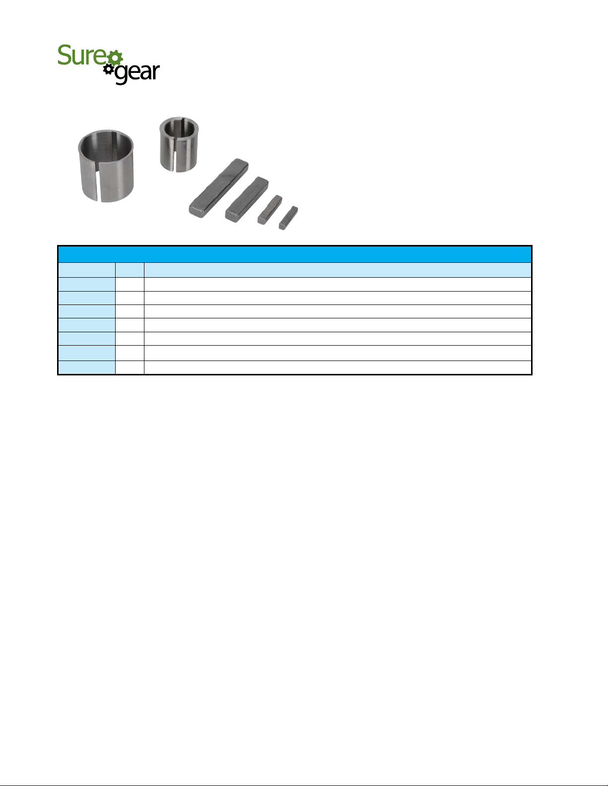
®
1-800-633-0405
Precision Servo Gearboxes
SureGear® Servo Gearbox Replacement Parts
SureGear® Precision Servo Gearboxes – Replacement Parts
Part Number Price Description
$4.00
PG050-KEY
PG070-KEY
PG090-KEY
PG120-KEY
PG155-KEY
PGA4-A5-BUSH
PGA6-BUSH
Output Shaft Key, replacement, 4 x 4 x 14 mm, for SureGear PGA050 series gearboxes.
$4.00
Output Shaft Key, replacement, 5 x 5 x 22 mm, for SureGear PGA070 and PGB070 series gearboxes.
$4.00
Output Shaft Key, replacement, 6 x 6 x 28 mm, for SureGear PGA090 and PGB090 series gearboxes.
$4.00
Output Shaft Key, replacement, 10 x 8 x 45 mm, for SureGear PGA120 and PGB120 series gearboxes.
$4.00
Output Shaft Key, replacement, 12 x 8 x 65 mm, for SureGear PGA155 and PGB155 series gearboxes.
Input Shaft Bushing, replacement, 28 x 22 x 30.5 mm, for all SureGear gearboxes using SVL-210(B) and SVM-210(B) SureServo
$20.50
motors.
$20.50
Input Shaft Bushing, replacement, 38 x 35 x 36 mm, for all SureGear gearboxes using SVM-220(B) and SVM-230(B) SureServo motors.
For the latest prices, please check AutomationDirect.com.
www.automationdirect.com
Motion Control
tMNC-197
 Loading...