

Page 1
A
C
I
utomation
omponents
nc.
ACI/TT-RSO-LCD
Installation and Operation Instructions
READ THESE INSTRUCTIONS BEFORE YOU BEGIN INSTALLATION
The ACI/TT-RSO-LCD is a 2-wire Loop Powered device that must be powered with an +8 to 35 VDC supply voltage
for both the temperature transmitter and the 4 to 20 mA adjustable setpoint. The display is powered from the current
loop from the temperature transmitter.
n TROUBLESHOOTING
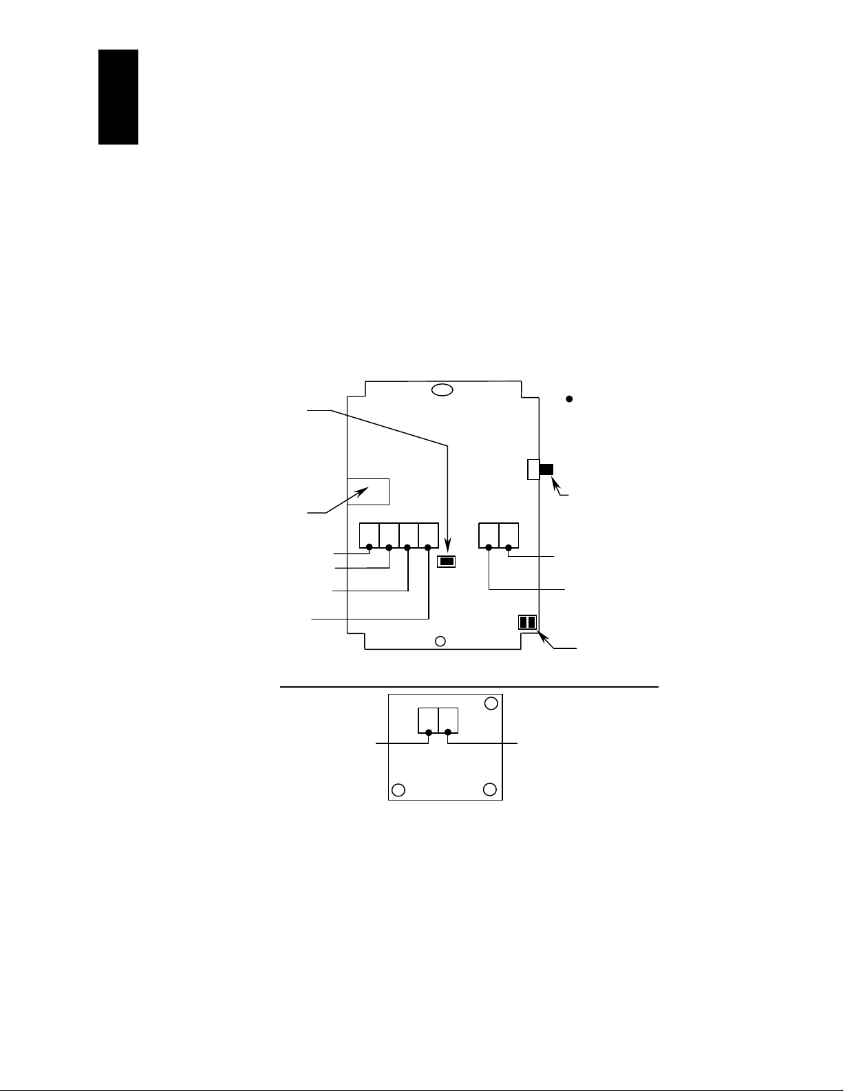
Temperature Transmitter Not Working Power supplied to transmitter (+), Verify that there is a common ground
4 to 20 mA Setpoint Not Working Power supplied to Setpoint (+), Verify that there is a common ground
Temperature Transmitter Reading High Verify that the (2) shunts are on the headers in the lower right hand corner
Display Not Working Verify that the Jumper on J8 is on. This completes the loop from the
temperature transmitter to the display. Verify that the display is plugged in
correctly.
nWIRING DIAGRAMS
Note: J8 must be installed
in order to place the
temperature transmitter
in series with the loop
powered LCD display
Wire Access Hole
“After Hours” Override N/O Dry Contact Closure
“After Hours” Override N/O Dry Contact Closure
“After Hours” Override N/O Dry Contact Closure
(-) 4-20mA Loop Output to Controller
(Local Setpoint or Temperature)
(+) 4 to 20 mA Loop Input from
Transmitter, Setpoint, or Control System
4 to 20mA Setpoint Wiring Diagram (Board on Back of Housing)
(+) +24 VDC Supply Voltage to
adjustable Setpoint Transmitter
LCD
O/R
- + - +
+ -
J8
to the controller
Temp
+8-35 VDC Supply Voltage to the
Temperature transmitter
(-) +4-20 mA Setpoint Output
to Controller
Note: This designates all
of the connections
“After Hours” N/O Override
Pushbutton
(-) 4 to 20 mA Loop Output to
Controller
Sensor Shunts
(Temperature)
nWIRING CONNECTIONS
A minimum of (2) to a maximum of (8) wires must be pulled for the ACI/TT-RSO-LCD to work properly. All of the
Setpoint connections are to be made to the board on the back of the housing. Be aware that the terminals are polarity
sensitive. ACI recommends the use of 18 to 22 AWG twisted pair wires or shielded cable for all sensor installations.
Verify that all connections are made correctly before turning on the power to the transmitter.
Note: When using the temperature transmitter and the LCD only, 2-wires are needed. Connect the
+8 to 35 VDC power supply to the terminal labeled (+ TEMP) and the 4 to 20 mA current loop
output to the controller should be connected to the (-) terminal of the LCD terminal block. Make
sure that Jumper J8 is on.
2305 Pleasant View Rd. Middleton Industrial Park Middleton, WI 53562
PH: (608) 831-2585 FAX: (608) 831-7407
II-25
Page 2
All ACI/TT and TTM temperature transmitters are non-polarity sensitive. That means that, the positive and negative
outputs of the power supply can be connected to either side of the power terminal block.
I
N =
where: N = number of transmitters
I = current available from power supply
22mA = maximum current draw of transmitter
e.g., If I = 1.5A then:
N = 1.5/22mA
N = 68
Therefore a 1.5A power supply will safely power up to 68 transmitters.
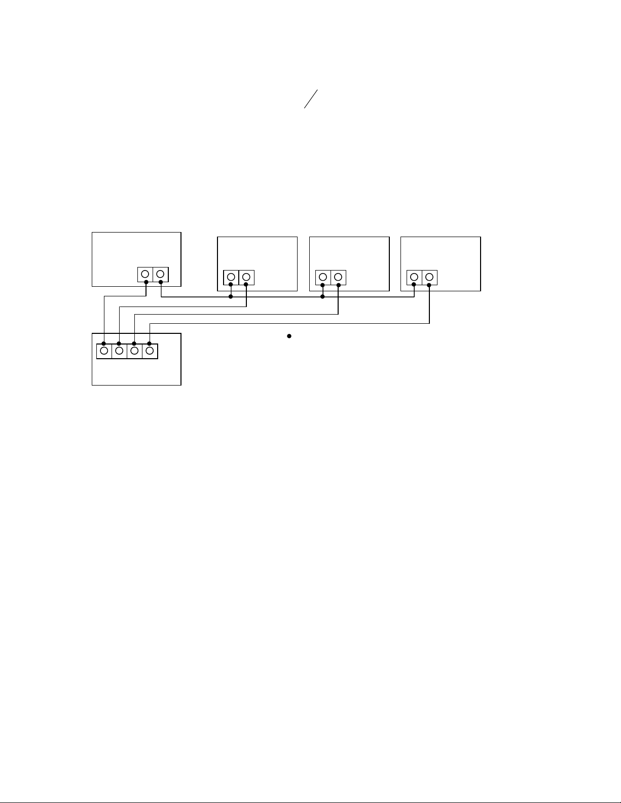
nSYSTEM WIRING DIAGRAM
22
mA
Power Supply
VDC
-
Gnd In1 In2 In3
Controller
nROOM TEMPERATURE TRANSMITTERS
This unit is suitable for either drywall or junction box mounting. First, remove the cover of the enclosure and mount the
base of the Room unit to the wall, using the (2) 6/32” x 1” screws that are provided. Once the base is mounted to the
wall, make all of the proper connections and then place the cover back onto the unit. Now fasten the cover, using the
(2) 1/16” Allen screws located at the bottom of the enclosure.
+
Temp.Transmitter #1 Temp.Transmitter #N Temp.Transmitter #2
+ -
+ -
= Connections
In1 = Controller Input #1
In2 = Controller Input #2
In3 = Controller Input #3
+ -
II-26
2305 Pleasant View Rd. Middleton Industrial Park Middleton, WI 53562
PH: (608) 831-2585 FAX: (608) 831-7407
 Loading...