

Page 1
Short Sensor
g
A
utomation
Common Input with RJ12 Phone Jack
C
omponents
I
nc.
Installation and Operation Instructions
READ THESE INSTRUCTIONS BEFORE YOU BEGIN INSTALLATION
All ACI thermistor and RTD temperature sensors are both non-polarity and non-position sensitive. All thermistor type
room units are supplied with a two-pole terminal block and all RTD’s can be supplied with either a two or three-pole
terminal block.
All of the following units are available with corresponding terminal blocks for all connections: Room with Setpoint (RS),
Room with Override (RO), Room with Setpoint and Override (RSO), and Room with Setpoint, Override, and RJ12
Communication Jack (RSO RJ12).
**Note: All Room with Override (RO) and Room with Setpoint and Override (RSO) sensors are shipped with the
Override in parallel with the sensor unless specified otherwise. If a Separate Input or Tenant Override is
Needed, see Figure #1 for the Override Options Jumper Settings.
All other configurations are supplied with 22 gauge lead wires and can be hooked up with any crimp style or wire nut wire
connectors. ACI recommends the use of 18 to 22 AWG twisted pair wires or shielded cable for all sensor installations.
n TROUBLESHOOTING
Sensor reads 0 ohms or very low Sensor or wires are shorted together
Sensor reads infinity or very high Sensor or wires are open
Erratic readings Bad wire connections - Condensation or Moisture problem
nWIRING DIAGRAMS
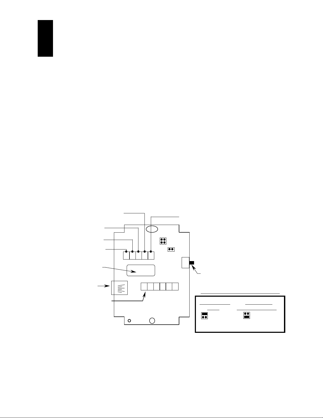
Tenant Override or Dry Contact Output to
Controller
+15 VDC Input for Sensor for
ACI/592-10K and ACI/592-10K-CS
only.
Terminals for RJ12 Communications
(Separate Input ONLY)
Thermistor and Override
Output to Controller
Thermistor, Setpoint, and
Override Common
Wire Access Hole
6 Pin RJ12
Communication Jack
J3
Membr ane
T
+ -
6
1
SEN O/R S
c
CSI Rev 7
E
1 2 3 4 5 6
Setpoint Output to Controller
Separate Input
J2
SW1
** NOTE: (J2) is only used for Connection of the Membrane Switch.
“After Hours” Normally-Open
Override Switch
Override Options Jumper Settings (J3)
Override Shorts Separate Input
Sensor
Fi
(Dry Contact Closure)
Short Sensor
Separate Input
ure #1
Short Sensor
Separate Input
.
2305 Pleasant View Rd. Middleton Industrial Park Middleton, WI 53562
PH: (608) 831-2585 FAX: (608) 831-7407
II-13
Page 2
nROOM TEMPERATURE SENSORS
This unit is suitable for either drywall mounting or junction box mounting. The room sensor is provided with screw
terminal blocks for all connections. Remove the cover from the unit and mount the housing base to the wall using the (2)
6/32" x 1" machine screws. Replace the cover and tighten down, using the (2) 1/16" Allen Screws located on the bottom of
the enclosure.
nDUCT AND DUCT AVERAGING SENSORS
Duct temperature sensors - Drill a 3/8" hole in the duct and insert the probe through the hole until the foam pad is tight to
the duct. Now insert the (2) screws through the mounting holes in flange and tighten until the unit is held firmly to the
duct.
Duct Averaging sensors - Drill a 3/8" hole in the duct and insert the averaging element through the hole until the foam pad is
tight to the duct. Now insert (2) screws through the holes in the mounting flange and tighten until the unit is held
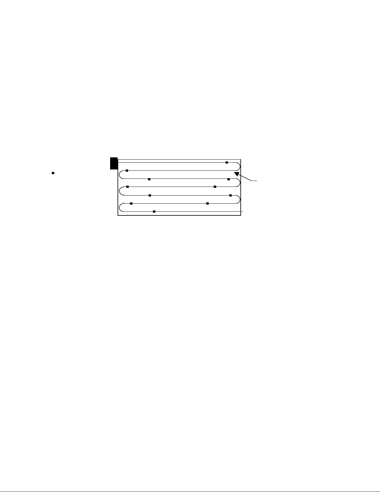
firmly to the duct. The sensor should then be strung in a criss-cross pattern throughout the duct (see Figure #2) using the
mounting clips provided, in a pattern that covers the greatest surface area of the duct, to insure that there is no stratification.
When bending the copper tubing, be careful that you use a gradual bend to not kink the copper tubing.
= Mounting Clips
8’, 12’, or 24’ Averaging
Element
Figure #2
nFLUID IMMERSION TEMPERATURE SENSORS
The ACI Fluid Immersion-type sensors are provided with a 2 ½", 4", or 6 ¼" insertion length, 304 series stainless steel
thermowell. The thermowell has a 1/2" NPT external or process thread and a 1/2" NPT internal or instrument thread. Heat
transfer compound may be used but is not necessary.
nSTRAP-ON TEMPERATURE SENSORS
The ACI Strap-On sensors, are provided in a NEMA 1 rated junction box with an adjustable 2" to 5" pipe clamp. The unit
should be mounted on the bottom side of the pipe to ensure proper heat transfer and a true temperature reading. Heat
transfer compound and insulating the sensor will help the overall accuracy of the sensor. By ordering extra straps and
fastening them together, it is possible to make them fit larger pipes.
nOUTSIDE AIR TEMPERATURE SENSORS
The ACI Outdoor Air temperature sensors are provided in a weatherproof enclosure. An optional weatherproof Aluminum
Bell Box or NEMA 4X Polycarbonate enclosure is also available upon request for an additional charge. All of the mounting
hardware is provided with the sensor. Be sure to mount the sensor out of direct sunlight, with the sensor probe pointing
downward.
nSTAINLESS PLATE TEMPERATURE SENSORS
The ACI Stainless Plate temperature sensors are mounted on the back of a 1 Gang stainless steel plate. The foam pad will
insulate the sensor from any drafts in the wall. (2) 6/32" x 1" machine screws are provided for junction box mounting.
Be sure that the sensor is not mounted on an outside wall, due to the extreme temperature changes from either drafts or heat
transfer.
II-14
2305 Pleasant View Rd. Middleton Industrial Park Middleton, WI 53562
PH: (608) 831-2585 FAX: (608) 831-7407
 Loading...