

Page 1
Installation and Operation Instructions
A/RH-LCD Series
Wiring Connections
ACI recommends that all A/RH-LCD humidity transmitters be wired with 16 to 22 AWG shielded wire for best
results.
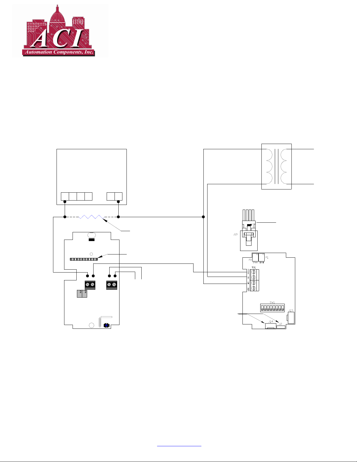
+24 VAC Input Wiring Diagram
Please Read Instruction Carefully Before Installation!
PLC or HVAC
Control System
AI1
to Controller
Analog Inputs
AI2 AI3 AI4
SPAN
TTRO LCD Rev 7
- LCD +
ZERO
Analog Input
Common
- -
- TEMP +
Optional 250 Ohm or
500 Ohm Load Resistor
for a 1 - 5 or 2 - 10 VDC
Output.
10 Pin LCD Socket
Optional Temperature
Sensor Output
to Controller (Resistive)
24 VAC
Secondary
RH 4-20 mA Output
+24 VAC Supply VoltageRH 4-20 mA Output
24 VAC Supply Common
Factory Use Only
120 VAC
Primary
Push tab in and pull up on the sensor
cable to remove from J13 connector
ON
87651 32 4
A/LCD-R 4-20 mA
(Loop Powered LCD Indicator)
Figure # 1
2305 Pleasant View Rd. Middleton Industrial Park Middleton, WI 53562
PH: (608) 831-2585 FAX (608) 831-7407
www.workaci.com
I0000150 Rev 4 Page 1 of 4
A/RH Transmitter
+24 VAC Input / 4-20mA Output
Page 2
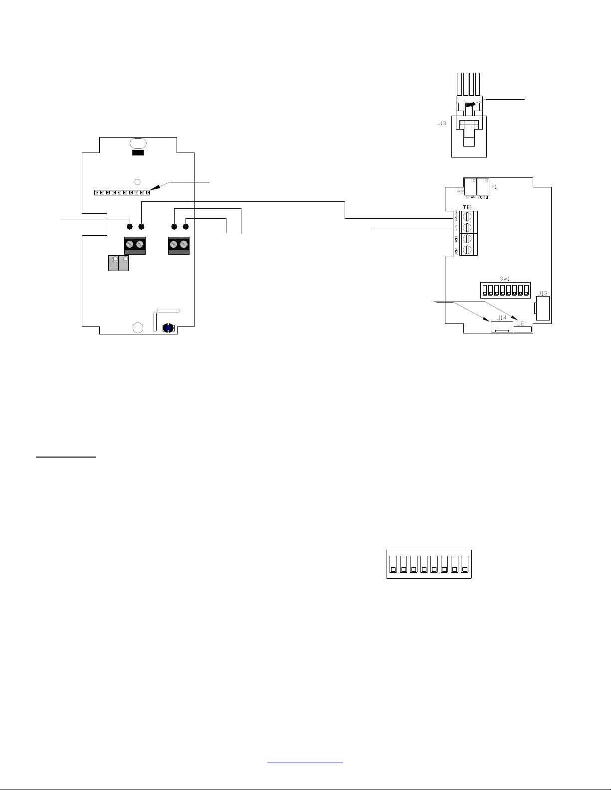
+24 VDC Input Wiring Diagram
10 Pin LCD Socket
Push tab in and pull up on the sensor
cable to remove from J13 connector
RH 4-20 mA Output
to Controller
SPAN
TTRO LCD Rev 7
ZERO
- TEMP +- LCD +
Optional Temperature
Sensor Output
to Controller (Resistive)
A/LCD-R 4-20 mA
(Loop Powered LCD Indicator)
Figure # 2
Installation
Space Mount:
The RH transmitter should be placed away from excessive
moisture, corrosive fumes, vibration, or extremely high
temperatures. The base of the housing was designed to mount
over a standard 2” X 4” junction box. Mount the unit on an
indoor wall, approximately 4 to 6 feet above the floor.
1) Make sure the unit receives adequate airflow.
2) Connect the wires to the terminal block as shown
in the wiring connection section.
3) Snap the cover into position.
4) Turn out the two Allen screws at the bottom of
the enclosure until the cover cannot be removed.
2305 Pleasant View Rd. Middleton Industrial Park Middleton, WI 53562
PH: (608) 831-2585 FAX (608) 831-7407
I0000150 Rev 4 Page 2 of 4
www.workaci.com
RH 4-20 mA Output
+24 VDC Supply Voltage
ON
Factory Use Only
A/RH Transmitter
+24 VDC Input / 4-20mA Output
OUTPUT SELECTIONS
Switches 6, 7, and 8 are used to set the output.
Refer to Figure #7 for switch settings.
Figure #7
Output Selection Switches (SW1)
4-20 mA Output
(Default)
ON
ON
32
OFF
1
54 876
Figure #7
87651324
Page 3

RH CALIBRATION INSTRUCTIONS
Note: This is only a single point calibration. All
transmitters are factory calibrated to meet/exceed
published specifications. Field adjustment should not be
necessary.
The dipswitch allows the user to calibrate the sensor through
the software. Setting switch 4 ON will put the transmitter into
setup mode allowing the increment and decrement to work.
Once in setup mode, the output will change to 50% (12mA for
4-20mA). Each increment or decrement step will cause the
output to change by 0.32mA for 4-20mA in setup mode. This
can be used to show the user how far offset the transmitter is.
To see the starting point again set switch 1 ON. This will show
the 50% output again. When the unit is out of setup mode the
output will go back to RH output.
Increment RH Output
This will shift the RH output linearly up in 0.5% steps. Switch
4 must be set to ON first. After switch 4 is on, each time
switch 5 is set ON the RH output will increase by 0.5%. The
increase goes into effect each time switch 5 is set to ON.
Decrement RH Output
This will shift the RH output linearly down in 0.5% steps.
Switch 4 must be set to ON first. After switch 4 is on, each
time switch 6 is set ON the RH output will decrease by 0.5%.
The decrease goes into effect each time switch 6 is set to ON.
Reset RH Output
This will reset the RH output back to the original calibration.
Switch 4 must be set to ON first. After switch 4 is on, toggle
switches 5 and 6 ON then OFF. After 5 and 6 are OFF slide
switch 4 OFF.
When all calibration is completed, remember to place the
switches back into the positions that correspond to the output
needed as shown in Figure #7.
Note: Potentiometers P1 (Zero) and P2 (Span) in Figures
#1 and #2 are not used for RH sensor calibration. They
are used for factory use only!
2305 Pleasant View Rd. Middleton Industrial Park Middleton, WI 53562
PH: (608) 831-2585 FAX (608) 831-7407
www.workaci.com
I0000150 Rev 4 Page 3 of 4
TEST INSTRUCTIONS
Test mode will make the transmitter output a fixed 0%, 50%,
or 100% value. The sensor will not affect the transmitter
output. This is used for troubleshooting or testing only.
Switches 1, 2, and 3 are used for test mode. The output will be
a fixed 0%, 50%, or 100% signal that corresponds to the
output selected with switches 6, 7, and 8. Refer to Figure #8
for switch settings.
RH CONVERSION FORMULAS
To convert output signal to percent RH:
Test Selection Switches (SW1)
0% RH Output
ON
ON
2 3
4 8
OFF
1
5 6 7
50% RH Output
ON
ON
2
3
6 81
4
OFF
5ON7
100% RH Output
ON
OFF
2 3
1 4 5 6
7 8
Figure #8
4-20 mA
((mA signal) -4) / 0.16 = percent RH
Example: 12mA output signal
(12-4) / 0.16 = 50% RH
Page 4
TROUBLESHOOTING
Problem:
No Reading
• Check that you have the correct supply
• Check that wiring configurations and all
• Verify that the terminal screws are all
Erratic Readings
• Verify that all of the wires are terminated
• Make sure that there is no condensation
• Check that the input power is clean. In
Inaccurate Readings
• If you suspect that the transmitter is not
voltage at the power terminal blocks.
DIP switch settings are as in Figures #1,
#2 and #7.
connected tightly and that all of the wires
are firmly in place.
properly.
on the board.
areas of high RF interference or noise,
shielded cable may be necessary to
stabilize signal.
reading within the specified tolerance,
please contact the factory for further
assistance.
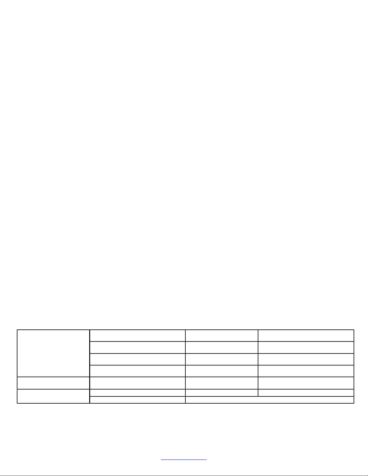
PRODUCT SPECIFICATIONS
Supp ly Voltag e
Supp ly Current
RH O utpu t
I0000150 Rev 4 Page 4 of 4
4-2 0m A Output: 250 Oh m L oa d 22 - 40
VD C / 22 - 28 V AC
4-2 0m A Output: 500 Oh m L oa d 24 - 40
VD C / 24 - 28 V AC (50 0 O hm Lo ad M ax)
24 mA M ax
2-W ire, 4 -2 0 mA
3-W ire, 4 -2 0m A
2305 Pleasant View Rd. Middleton Industrial Park Middleton, WI 53562
PH: (608) 831-2585 FAX (608) 831-7407
www.workaci.com
RH M easu re me nt R an ge
RH A ccuracy @ 7 7oF (25oC)
Re pe atab ility
Op er ating Hu mi dity E nviro nment
Op er ating Te mp . E nvir on me nt
Sto rag e T emp. Ran ge
0 - 100 % R H
1% o ver 2 0% span ( betw een 2 0 to 90 % )
±
± 2% , 3% , or 5% from 10 to 95 %
0.5% R H
0 to 95 % RH
32 to 1 22°F (0 t o 50°C)
-40 t o 1 60°F (-40 to 7 1°C)
 Loading...