

Automatic Technology SecuraCode CRX, SecuraCode CRX-2, SecuraCode CRX-1 Instructions Manual
Thank you for purchasing the ATA CRX Series SecuraCode
®
Stand Alone Receiver. Familiarise yourself with the following
instructions prior to commencing set up. Store this information
in a safe place for future reference.
OPERATION
The CRX series receivers have relays on board which provide
normally open or normally closed contact for controlling
virtually any electronic device. The relays can be programmed
to any of three modes - pulse, hold or timer. One or both relays
can be programmed with any of the three modes.
SETTING RELAY OPERATING MODES
Pulse Mode - Relay contact is active whilst transmitter buton is
pressed.
Hold Mode - Relay changes state at each press of transmtter
button. Hold, Release, Hold, etc. (like an on/off switch).
Timer Mode - Relay will remain active for the programmed
duration.
Note: Timer mode is selectable only with the ATA Programmer.
Refer to the Programmer’s manual for instructions on setting
Timer mode.
RELAY-1 Pulse Mode - Bridge the two pins on JP1 jumper.
RELAY-1 Hold Mode - Remove JP1 jumper or do not bridge
the two pins.
RELAY-2 Pulse Mode - Bridge the two pins on JP2 jumper.
RELAY-2 Hold Mode - Remove JP2 jumper or do not bridge
the two pins.
UNIVERSAL PROGRAMMER
An ATA Universal Programmer can be used to program modes
and store transmitter codes from the receiver. For more details
please contact ATA.
STORING TRANSMITTER CODE
Make sure to install the battery in the transmitter correctly.
1. Press and hold SW1 (for Relay 1) or SW2 (for Relay 2) on
the receiver board.
2. Press the transmitter button you would like to use to control
the device for two seconds.
3. Release the transmitter button and pause for two seconds.
Press the same button again for two seconds.
4. Release SW button.
5. Press the transmitter button to test operation.
Note: To remove a single transmitter’s code from the receiver
memory repeat steps 1-5 above .
DELETING ALL STORED TRANSMITTER CODES
1. Turn the power off to the receiver.
2. Press and hold SW1 button.
3. While holding SW1 turn power on again. After 15 seconds
the Coding LED will illuminate to indicate that the
receivers memory has been cleared.
4. Release SW1. All the stored codes should now be
deleted. Confirm this by pressing the transmitters
previously used to operate the device. There should be no
response.
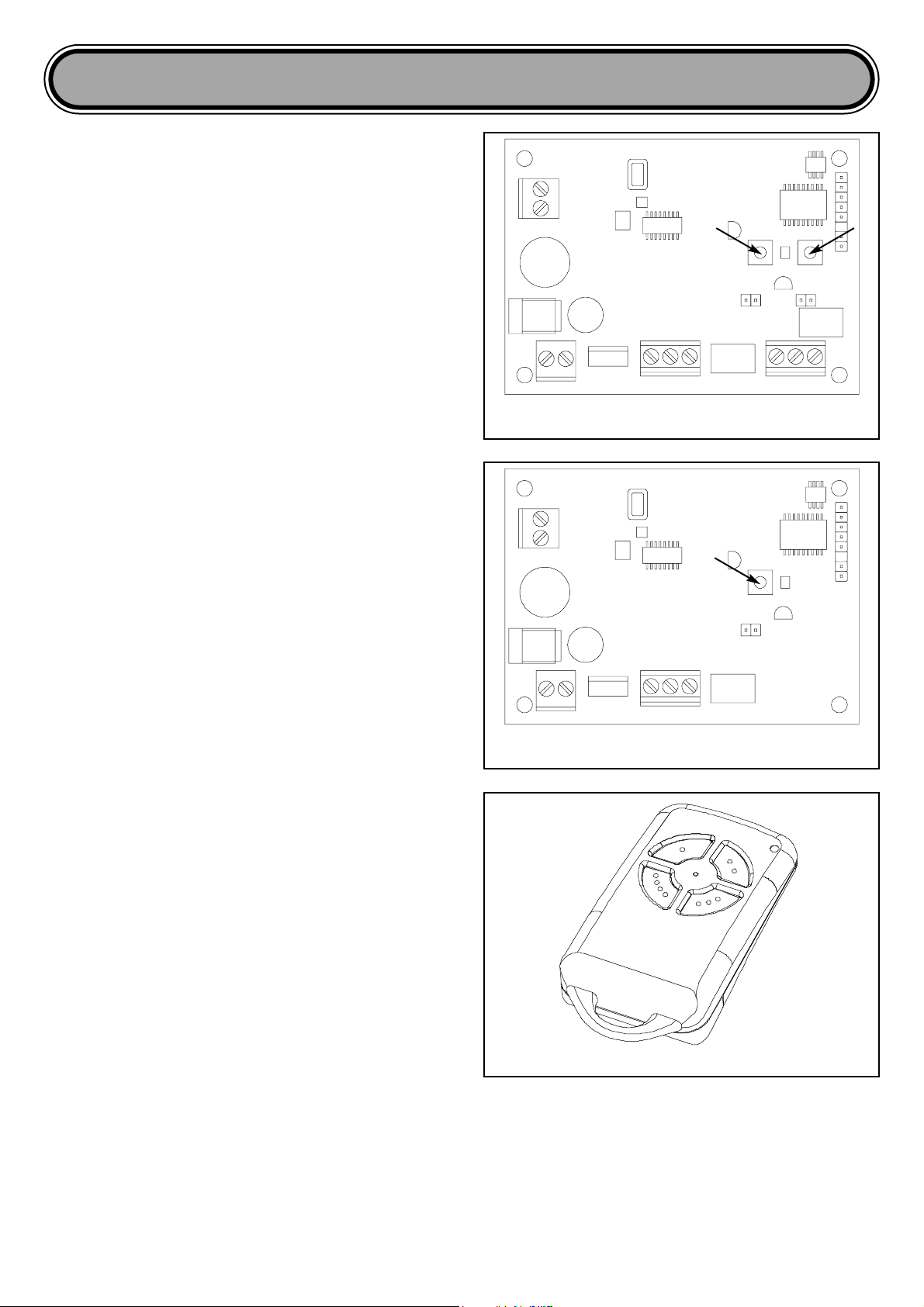
CRX-2 Stand Alone Receiver
SW1 SW2
CRX Series Stand Alone Receiver Instructions
CRX Series Stand Alone Receiver Instructions
PTX-4 SecuraCode®Keyring Transmitter
JP1 JP2
ANTENNA
RELAY 1 SKT RELAY 2 SKTPWR SKT
AC SKT
CRX-1 Stand Alone Receiver
SW1
JP1
ANTENNA
RELAY 1 SKTPWR SKT
AC SKT
LED
LED

WARRANTY
Subject to all of the matter set out below, Automatic Technology Australia Pty Ltd (“ATA”) WARRANTS for twelve (12) months from
the date of purchase (specified in the tax invoice receipt) that the CRX Series Receiver (the “Product”) is free of any defects in
material and workmanship rendering it unmerchantable.
This warranty referred to above applies only where:
a) the consumer seeking to rely on the said warranty;
1) returns the Product which it claims to be defective; and
2) presents the relevant sales docket and this warranty document, to the retailer from whom the Product was purchased to
confirm that date of purchase; and
b) the purchaser notified ATA or the retailer from whom the Product was purchased of the alleged defect in the Product
immediately upon experience or learning of the alleged defect.
Except for the warranty against defects in material and workmanship set out above, ATA gives no warranties of any kind whatsoever,
whether express or implied or whether statutory or at common law, in relation to the Product, and all warranties of fitness for
particular purpose and other warranties of whatsoever kind relating to the Product are hereby declaimed. Without limiting the
generality of the foregoing, ATA disclaims any liability of whatsoever nature in respect of any claim or demand loss or damage which
arise out of;
a) accidental damage to or normal wear and tear to the Product or to the Product’s components;
b) flood, rain, water, fire or lightning;
c) incorrect, improper or unreasonable maintenance and/or use;
d) installation, adjustment or use other than ATA which is not in accordance with the instructions set out in installation instructions
incorporated in the document;
e) attempted or complete modification or repairs to the Product carried out by a person who is not authorised by ATA to carry out such
modification or repairs;
f) radio (including citizen band transmission) or any electronic interference,
g) damage caused by electrical surges,
h) damage caused by insects.
ATA’s liability under the warranty set out above is limited, at ATA’s absolute option, to replacing or repairing the Product which ATA,
in its unfettered opinion, considers to the defective either in material and/or workmanship or to credit the consumer with the price at
which the Product was purchased by the consumer. Where the Product is retailed by any person other than ATA, except for the
warranty set out above, such person has no authority from ATA to give any warranty or guarantee on ATA’s behalf in addition to the
warranty set out above.
Automatic Technology Australia Pty Ltd
17-19 Advantage Rd Highett Vic 3190 Australia
T: +61 3 9532 2788 F: +61 3 9532 2799
E: sales@ata-aust.com.au W: www.ata-aust.com.au
© July 2004. All rights reserved. SecuraCode®is a registered trademark of Automatic Technology Australia P/L.
In an ongoing commitment to product quality ATA reserve the right to change specifications without notice. Printed for Export.
SPECIFICATIONS
Power Supply: 12V-24V AC or DC
Frequency: 433.92MHz
Memory Capacity: 111 Transmitters
Programmable Modes: Pulse, Hold. Timer*
Controlling Outputs (CRX-1): 1 x Common
1 x Normally Open
1 x Normally Closed
N.B. CRX-2 has two relays and two of each controlling output
Relay Contact Rating: 1 amp @ 24 volts DC
Antenna Wire Length**: 170mm
*Timer mode available with ATA's Universal Programmer.
** An optional co-axial antenna is available for use with the
receiver in difficult reception areas. The antenna has to be
mounted as high as possible so that it is not obstructed, e.g. on
top of a fence, or on a wall at the front of a garage, etc. Connect
the core of co-axial lead to replace the existing antenna wire
(inner screw socket). Connect shield to the spare (outer) screw
socket.
ANTENNA
AC SKT
CONNECT CO-AX
SHIELD
CONNECT CO-AX
CORE
PWR SKT
 Loading...