


Doc # 160055_02
Part # 13418
Released 21/02/19
High Rolling Door Opener
GDO-12
HiR
2
GDO-12V1 Hiro™ Installation Instructions
WARNING!: It is vital for the safety of persons to follow all
instructions. Failure to comply with the installation instructions
and the safety warnings may result in serious personal injury
and/or property and remote control opener damage. Please
save these instructions for future reference.
ELECTROCUTION!: To reduce the risk of electric shock, this
equipment has a grounding type plug that has a third (grounding)
pin. This plug will only fit into a grounding type outlet. If the
plug does not fit into the outlet, contact a qualified electrician
to install the proper outlet. Do not change the plug in any way.
This operator is not equipped for permanent wiring. Contact a
qualified electrician to install a suitable receptacle if one is not
available.

Installation Instructions GDO-12V1 Hiro
™
3
1. Safety Information 4
2. Specifications 5
3. Set Up Requirements 6
4. Pre-Installation Requirements 7
4.1 Door Operation 7
4.2 Unsuitable Door Types 7
4.3 Position 7
4.4 Power Supply 7
4.5 Sideroom 7
4.6 Forks 7
5. Opener Safety & Security 8
5.1 The Door CAN NOT be used by the opener when: 8
5.2 The Door CAN be used when: 8
5.3 To Disengage the Opener: 8
5.4 To Re-Engage the Opener: 8
6. Installation Instructions 8
6.1 Door Preparation 9
6.1.1 Preparation 9
6.1.2 Pinning the Door to the drum: 9
6.2 Propping the Door 10
6.3 Fitting the Opener 10
6.4 Setting Limits 11
6.4.1 Setting Travel Limits 11
6.4.2 Set the Limit Positions 11
6.4.3 Resetting the Door Limit Positions 11
6.4.4 Setting Partial Open Position 11
6.4.5 Checking Partial Open Position 11
6.5 Safety Obstruction Force Test 12
6.5.1 Testing Close Cycle 12
6.5.1 Testing Open Cycle 12
6.6 Coding Transmitter 13
6.6.1 Transmitter Button to Operate Door 13
6.6.2 Erasing Programmed Codes 13
6.6.3 Selecting The Function To Be Coded 13
6.6.4 Activate Remote Code Set Mode 13
7. Operation Instructions 14
7.1 How to Use Your Opener 15
7.1.1 To Operate the opener: 15
7.1.2 Replacing the Battery: 3V Lithium Battery CR2032. 15
7.1.3 Battery Disposal 15
7.2 User Operating Controls 16
7.3 Door Status Indicators 16
8. Maintenance 17
9. Troubleshooting Guide 18
10. Appendix 19
A - Adjustment Mode Parameters 19
B - Motor Speed 19
C - LED Status 20
D - Setting Limits via Transmitter 21
E - Additional Transmitter Functions 22
11. Warranty and Exclusion of Liability 23
Automatic Technology Australia Pty Ltd to the extent that such may be lawfully excluded hereby expressly disclaims all conditions or warranties, statutory or
otherwise which may be implied by laws as conditions or warranties of purchase of an Automatic Technology Australia Pty Ltd Garage Door Opener. Automatic
Technology Australia Pty Ltd hereby further expressly excludes all or any liability for any injury, damage, cost, expense or claim whatsoever suffered by any
person as a result whether directly or indirectly from failure to install the Automatic Technology Australia Pty Ltd Garage Door Opener in accordance with these
installation instructions.
High Roll Up Garage Door Opener
GDO-12
HiR

4
GDO-12V1 Hiro™ Installation Instructions
1. Safety Information
Please read these important safety rules
These safety alert symbols indicate a personal
safety or property damage instruction exists.
READ THESE INSTRUCTIONS CAREFULLY.
This automatic garage door operator is designed and tested
to offer safe service provided it is installed and operated
in strict accordance with the following safety rules. Failure
to comply with the installation instructions and the safety
warnings may result in death, serious personal injury and/or
property damage.
WARNING!
• To reduce the risk of injury to persons – Use this operator only
with a rolling door. The drive must not be used with a door
incorporating a wicket door, unless the drive cannot be operated
with the wicket door open.
• This operator is a plug in domestic appliance and is designed
for indoor use only. It must be installed in a dry position that is
protected from the weather.
• Activate the operator only when the garage door is in full view,
free of obstructions and with the operator properly adjusted.
• The network device allows for operation of the door when not
in line-of-sight of the door and operator. Therefore the door
may operate unexpectedly, therefore do not allow anything to
stay in or near the path of the door.
• Watch the moving door and keep people away until the door is
completely opened or closed.
ELECTROCUTION:
• Installation and wiring must be in compliance with your local
building and electrical codes.
• This operator is not equipped for permanent wiring. Contact a
qualified electrician to install a suitable receptacle if one is not
available.
• To reduce the risk of electric shock, this equipment has a
grounding type plug that has a third (grounding) pin. This plug
will only fit into a grounding type outlet. If the plug does not fit
into outlet, contact a qualified electrician to install the proper
outlet. Do not change the plug in any way.
• If the power cord is damaged, it must be replaced by the
manufacturer, its service agent or a similarly qualified person in
order to avoid a hazard.
• Connect the power cord only to properly earthed mains. If an
extension lead must be used, make sure it is a 3-core lead and
approved to 7 amp capacity.
• This unit is not user serviceable. Unplug the power cord before
removing the cover. Ensure that the power cord is attached
clear of all moving parts. Ignoring these instructions can cause
electric shock.
CAUTION:
• If your garage has no pedestrian entrance door, an emergency
access device should be installed. This accessory allows manual
operation of the garage door from outside in case of power failure.
• Keep the garage door balanced. Sticking or binding doors must be
repaired. Garage doors, door springs, brackets and their hardware
are under extreme tension and can cause serious personal injury.
Do not attempt any garage door adjustment. Do not use if repair
or adjustment is needed. Call for professional garage door service.
• Position the Garage Door Operator so that the power plug is
accessible when inserted into the power outlet.
• Install the wall transmitter in a location where the garage door is
visible, but out of the reach of children at a height of at least 5 feet
(1.53m).
• To avoid serious personal injury from entanglement, remove all
unnecessary ropes or chains and disable any equipment such as
locks which are not needed for powered operation.
• Do not wear rings, watches or loose clothing while installing or
servicing a garage door operator.
• Ensure ladder is the correct type for the job and is on flat ground.
We recommend the user has 3 points of contact while on ladder.
• Activate the operator only when the garage door is in full view,
free of obstructions and with the operator properly adjusted.
• The operator is not intended for use by young children or infirm
persons without supervision.
• Keep transmitters away from children.
• Do not allow children to play with door controls.

Installation Instructions GDO-12V1 Hiro
™
5
2. Specifications
Technical Specifications GDO-12V1
Rated voltage range 230V - 240V a.c
Rated frequency 50Hz / 60Hz
Rated power input 150W
Rated operating time: 6 min
Rated operating temperature -10
o
C to +55 oC
Rated load 500N
Maximum turns of door drum:
Max door weight:
Maximum door area (wind-lock):
Maximum door area:
Door must be well balanced and able to be operated by hand,
as per warranty conditions and standard AS/NZS 4505:2012
6 turns of the drum wheel
270kg *
22m2 **
28m
2
Minimum sideroom 35mm
IP rating IP20
Receiver type Multi-frequency UHF FM
(433.47, 433.92 & 434.37MHz)
Receiver code storage capacity 64 x 4-button Transmitters
Number of code combinations Over 100 billion random codes
Transmitter battery CR2032 (3 Volts)
Courtesy light LED (Light Emitting Diodes)
*: Gross door weight, incl. all fittings
**: Windy conditions can activate the obstruction feature of the opener.
6
GDO-12V1 Hiro™ Installation Instructions
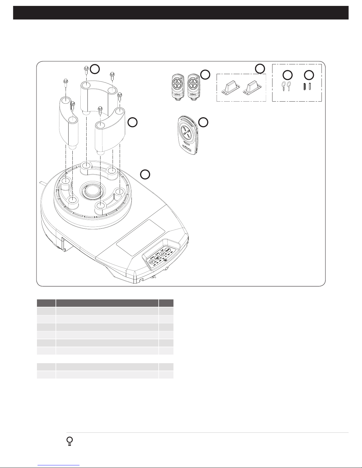
3. Set Up Requirements
Fig 3.1
3.1 Kit Contents
ITEM DESCRIPTION QTY
1 GDO-12 POWER DRIVE UNIT 1
2 INTERNAL GEAR ADAPTER (FORKS) 3
3 HEX SERRATION HEAD SCREW M6 X 20 6
4 4 BUTTON TRANSMITTERS 2
5 4 BUTTON WALL TRANSMITTER 1
6 LOCKING BAR COVERS 2
GUIDE PACK VR12
7 SCREW-EYE 2
8 PLASTIC WALL PLUG 6.9 X 25 (1”) 2
1
2
3
4
5
6
7
8
Installation Instructions GDO-12V1 Hiro
™
7
4. Pre-Installation Requirements
IMPORTANT SAFETY INSTRUCTIONS FOR INSTALLATION
Warning: Incorrect installation can lead to severe injury.
Follow ALL installation instructions.
NOTE: Planetary chain equipment must be removed from
the door prior to installation of GDO-12V1 HiRo™.
4.1 Door Operation
The door must be in good operating condition. The maximum
effort to move the door up or down, from stationary, should not
exceed 200 Newtons (20 kg force) at the bottom rail.
Lift the door to about halfway. When released, the door should
stay in place supported entirely by its springs. Raise and lower the
door to check for binding or sticking.
The door may need to be serviced to meet these requirements –
refer to the door manufacturer’s servicing instructions or contact
an authorised dealer.
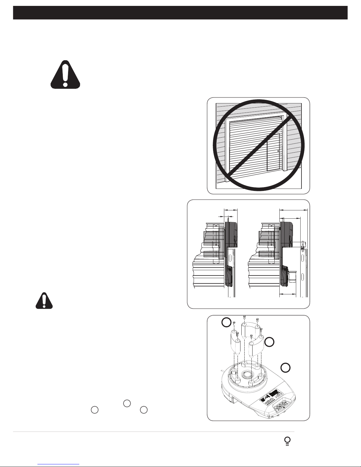
4.2 Unsuitable Door Types
The fitting of an opener to doors with removable mullions or
doors incorporating a wicket door is not recommended (Fig. 4.1).
4.3 Position
The opener can be installed on either the right or left hand side
of the door (when viewed from inside the garage). The opener is
factory set for right hand side installation.
This opener must be installed in a dry position that is protected
from the weather. Moisture or corrosion damage is not covered
by the Warranty.
4.4 Power Supply
Properly earthed 3 pin single-phase power is required.
WARNING! Using a portable power generator
is not recommended. The opener may appear to
malfunction due to spikes, surges and fluctuations
in the generated voltage.
4.5 Sideroom
The minimum sideroom required from the edge of the door
curtain is 35 mm to the inside of the door bracket, and 80mm to
the wall. If the Battery Backup is to be fitted, at least 130mm to
the bracket is required.
Therefore the recommended sideroom from the edge of the door
curtain is 130mm to the inside of the door bracket, and 170mm
to the wall as per diagram. (Fig. 4.2).
NOTE: The door axle diameter must not exceed 35mm.
4.6 Forks
Attach and secure the three (3) forks 2 with the six (6) hex
serration head screws 3 to the drive unit 1 (Fig. 4.3). All
forks must be used and properly engaged into the drum of the
door for the opener to work effectively.
Fig 4.2
Fig 4.3
2
1
3
Fig 4.1
130mm
80mm 170mm
35mm
Recommended Side roomMinimum Side room
105mm

8
GDO-12V1 Hiro™ Installation Instructions
5. Opener Safety & Security
MANUAL RELEASE
WARNING! When operating the manual
release (while the door is open) the door
may fall rapidly due to weak or broken
springs, or due to being improperly
balanced.
Do not disengage the operator to manual
operation with children/persons or any
objects including motor vehicles within
the doorway.
1.
TO DISENGAGE:
PULL HANDLE DOWN
& RELEASE
2.
TO RE-ENGAGE:
REPEAT ACTION
PULL
HANDLE
IN THE EVENT THE DOOR BECOMES OBSTRUCTED
DETACH DOOR FROM OPENER AS FOLLOWS:
5.1 The Door CAN NOT be used by the opener when:
a. There is a locking device installed.
b. There is a power failure.
5.2 The Door CAN be used when:
a. There is an emergency, by disengaging the opener.
b. There is a power failure, by disengaging the opener.
5.3 To Disengage the Opener:
a. It is recommended to do so with the door in the closed position.
b. Pull down on the manual release cord, until you hear a click.
c. Move the door manually.
5.4 To Re-Engage the Opener:
a. Check the door has not been locked by a locking device.
b. Pull down on the manual release cord, until you hear a click.
c. The door will now operate from the opener.
CAUTION: When the opener is manually disengaged,
the door is no longer locked. To lock the door manually,
re-engage the opener after the door is closed.
WARNING! Please test the manual release
mechanism to ensure that the manual release is easy
to operate. No more than 20 kg of force should be
required to disengage the door using the manual
release cord. If excessive force is required reset the
close limit position (Section 6.4.3 Resetting Door
Limit Positions).
6. Installation Instructions
IMPORTANT INSTALLATION INSTRUCTIONS.
WARNING - To reduce the risk of severe injury or death:
(1) READ AND FOLLOW ALL INSTALLATION INSTRUCTIONS.
(2) Install only on a properly operating and balanced garage door. An improperly balanced door has the potential to
inflict severe injury. Have a qualified service person make repairs to cables, spring assemblies, and other hardware
before installing the opener.
(3) Remove all pull ropes and remove or make inoperative, all locks connected to the garage door before installing
opener.
(4) Where possible, install the door opener 2.14m or more above the floor. For products having an emergency release,
mount the emergency release 1.83 above the floor and avoiding contact with vehicles to avoid accidental release.
(5) Do NOT connect the opener door operator to source of power until instructed to do so.
(6) Locate the control button:
(i) within sight of door,
(ii) at a minimum height of 1.53m above floors, landings, steps or any other adjacent walking surface so small
children are not able to reach it, and
(iii) away from all moving parts of the door.
(7) Install the Entrapment Warning Label next to the control button in a prominent location. Install the Emergency
Release Label. Attach the marking on or next to the emergency release.
(8) After installing the opener, the door must reverse within 2 seconds when it contacts a 1 1/2 -inch high object (or a 2
by 4 board laid flat) on the floor.
(9) For products having a manual release, instruct the end user on the operation of the manual release. Exception: For
horizontally sliding doors, Item 2 shall be replaced with “Have a qualified service person make repairs and hardware
adjustments before installing the opener.

Installation Instructions GDO-12V1 Hiro
™
9
6.1.1 Preparation
a. Check the door’s operation:
i. The door must travel smoothly and be easy to operate by hand.
ii. Adjust any tight or twisted guides.
iii. Clean the guides if there is any oil or wax present using a suitable white spirit. The only lubricant suitable for use on
door guides is silicon spray. DO NOT use WD-40, RP-7, petroleum grease, or similar.
b. Fit the weight bar 9 and install the locking bar covers 6 if there are locking bar holes in the guides.
c. Affix the warning labels supplied with this opener in a prominent place where they are clearly visible.
d. Choose the side where the opener will be installed ensuring there is sufficient sideroom.
Check that the door is still balanced and smooth to operate. If it is not, the door may require servicing (refer to door
manufacturer’s instructions).
6.1 Door Preparation
6.1.2 Pinning the Door to the drum:
Pinning the door’s curtain to its drum maintains security when the opener is
closed. If the curtain is not pinned the door can be partially opened manually.
a. Fully close the door.
b. Mark a minimum of two (2) drill holes on the drum to each end of the door.
c. Drill holes using 3.2mm (1/8”) drill bit.
d. Fit M10 x 32mm screws and washers (not supplied) to each of the four (4)
holes. This screw should be positioned as low as possible in the grove, but
make sure that it does not alter the curtain’s normal lead in to the guide.
BALLOONING DOOR
PINNED DOORFREE DOOR
Pin Points
Screw into the
low part of
grove

10
GDO-12V1 Hiro™ Installation Instructions
NOTE - For minimum sideroom installations, the door may have to
be taken down.
Fig 6.2
Tighten U bolts
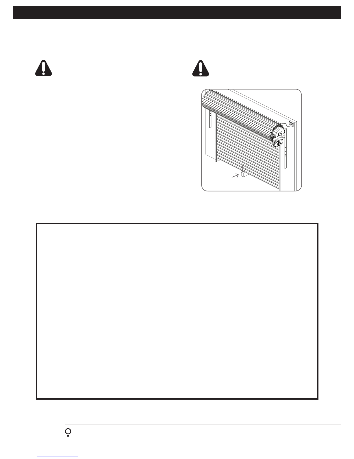
6.2 Propping the Door
WARNING! The opener must not
be used with a door incorporating a
wicket door.
WARNING! The door and its springs
are under significant tension.
Adjustments should only be carried
out by experienced persons, as
this function can be dangerous if
not performed under strict safety
procedures.
Fig 6.3
6.3.1 Mounting The Opener
a. Check the drive gear rotates freely, by pulling the string handle
down (there will be a click) to disengage opener. Then move the
forks from side to side by hand
b. Slide the opener over the door axle and into the drum of the door
(Fig. 6.3).
c. Ensure the internal gear is pushed in as far as possible (without
interfering with the door curtain) and that the door drum’s wheel
spokes are completely between the opener’s drive forks.
d. Tighten the pipe clamp.
e. Remove the safety rope and door stand or prop.
f. Connect the power cort to a suitable powerpoint, but DO NOT
switch on.
g. Secure the power cord away from any moving object (e.g the door)
with the cable clip supplied.
h. With the opener still disengaged, pull the door up and down to
make sure it runs freely.
NOTE - If the manual release handle is more than 1.8 metres from floor
level when the opener is installed, extend the handle to a height less
than 1.8 metres.
6.2.1 Door prop preparation
a. At the end opposite to where the opener will be fitted, check that
the door axle is tightened to the bracket securely. (Fig. 6.2)
b. Open the door completely and tie safety ropes around the door
roll approximately 300 mm from each end. Do not tie the ropes too
tight as damage to the curtain may ensue.
c. At the end where the opener is to be fitted, support the door with
a safe and suitable lifter.
WARNING! Make sure the door is secure in the support,
is stable and will not move.
d. At the end where the opener will be fitted, use pen to mark the
position of the saddle on the door bracket and the position of the
door bracket on the wall to assist in reassembling.
e. Remove the bolts and saddle from the door bracket.
f. Raise the door off the door bracket and secure in the support.
6.3 Fitting the Opener
NOTE: Use torque of 60Nm
when tightening nuts.

Installation Instructions GDO-12V1 Hiro
™
11
6.4.3 Resetting the Door Limit Positions
Limit positions can be deleted by:
a. Switching off power to the unit.
b. Pressing and holding the RED STOP / SET button and
switching power on to the unit will clear the settings
memory
(the LIMIT LED will flash).
6.4.4 Setting Partial Open Position
After completing the limit setup procedure the Parital
Open position is automatically set to a position which
is approximately in the middle of the door travel. The
position can be manually set by following the below
process:
a. Drive and stop the door at the desired Partial Open
position by using a transmitter or control panel.
b. Press the MODE button twice to highlight the LIMIT
LED.
c. Use the BLUE CLOSE or GREEN OPEN buttons to
scroll through to highlight the PART LED.
d. Press and hold the RED STOP / SET button for 2
seconds and release.
6.4.5 Checking Partial Open Position
When activated by a transmitter button which is coded
as PART mode, the opener drives the door to the preset
position from either above or below. If a PART Mode
button is pressed while the door is moving, the door will
stop. If a PART Mode button is pressed when the door is
in the PART position, then the door will close.
6.4.1 Setting Travel Limits
a. Move the door to the half way position.
b. Engage the opener by pulling down on the manual release
string until a click sounds.
c. Switch power on to the opener.
d. Press the BLUE CLOSE button to close the door:
(i) If the motor drives the door in the wrong direction press
the GREEN OPEN and BLUE CLOSE buttons together to
reverse the motor direction.
WARNING! In setting the close limit position, do
not force the door into the floor with excessive
force, as this can interfere with the ease of
operation of the manual release mechanism.
6.4.2 Set the Limit Positions
The Limit Positions can vary due to site conditions, such as
uneven ground. When setting the Close limits, ensure the
position is when the door makes first contact with the ground.
Alternatively for the Open limits the position should be at the
height of the garage opening.
a. Press and hold the BLUE CLOSE button to close the door.
b. When the door is at the desired close position, press the
RED STOP/ SET button to record the close limit position.
The display will change and green open LED will start to
flash.
c. Press and hold the GREEN OPEN button to open the door.
When the door is at the desired open position, release
the OPEN button. If the door overshoots, press the CLOSE
button to move the door in the CLOSE direction.
WARNING! Once the next step is performed, the door
will automatically close and open to calculate force
settings. Keep persons and objects clear of the door.
d. Press the RED STOP/SET button to store the open limit. The
door will now automatically close and open to calculate the
safety obstruction settings.
6.4 Setting Limits
HELPFUL TIP: Alternatively set travel
limits using a transmitter, allowing
free movement around the garage to
better assess the desired limit positions.
See Appendix D.
tip
Fig 6.4
HELPFUL TIP: The openers motor speed
can be adjusted during limit setting. See
Appendix B for changing motor speed.
tip
12
GDO-12V1 Hiro™ Installation Instructions
6.5 Safety Obstruction Force Test
40mm Block of
wood
WARNING! Take care when testing or adjusting the
Safety Obstruction Force. Excessive force may cause
SERIOUS PERSONAL INJURY and/or PROPERTY
DAMAGE.
6.5.1 Testing Close Cycle
a. Press the OPEN button to open the door.
b. Place a piece of timber approximately 40mm high on the
floor directly under the door (Fig. 6.5.1).
c. Press the CLOSE button to close the door. The door should
strike the object and start to re-open.
6.5.1 Testing Open Cycle
a. Press the CLOSE button to close the door.
b. Press the OPEN button to open the door. When the door
reaches the half open point, grab the bottom rail of the door
firmly and the door should stop.
c. If the door does not reverse readily when closing, or stop
when opening, the force may be excessive and need
adjusting.
Fig 6.5
WARNING! If the door fails these tests, put
the opener into manual mode, only operate
the door by hand and call for service.
TRANSMITTERS COMPLIANCE STATEMENT
TRANSMITTERS COMPLY WITH ALL UNITED STATES AND CANADIAN LEGAL REQUIREMENTS AS OF THE DATE
OF MANUFACTURE. TO COMPLY WITH FCC PART 15 AND OR RSS 210 OF INDUSTRY CANADA (IC) RULES,
ADJUSTMENT OR MODIFICATIONS OF THIS RECEIVER AND / OR TRANSMITTER ARE PROHIBITED, EXCEPT FOR
CHANGING THE CODE SETTING OR REPLACING THE BATTERY. THERE ARE NO OTHER USER SERVICEABLE
PARTS. TESTED TO COMPLY WITH FCC STANDARD FOR HOME OR OFFICE USE. OPERATION IS SUBJECT TO THE
FOLLOWING TWO CONDITIONS:
(1) THIS DEVICE MAY NOT CAUSE HARMFUL INTERFERENCE, AND
(2) THIS DEVICE MUST ACCEPT ANY INTERFERENCE RECEIVED, INCLUDING INTERFERENCE THAT MAY CAUSE
UNDESIRED OPERATION.
NOTE: THIS EQUIPMENT HAS BEEN TESTED AND FOUND TO COMPLY WITH THE LIMITS FOR A CLASS B DIGITAL
DEVICE, PURSUANT TO PART 15 OF THE FCC RULES. THESE LIMITS ARE DESIGNED TO PROVIDE REASONABLE
PROTECTION AGAINST HARMFUL INTERFERENCE IN A RESIDENTIAL INSTALLATION. THIS EQUIPMENT
GENERATES, USES AND CAN RADIATE RADIO FREQUENCY ENERGY AND, IF NOT INSTALLED AND USED IN
ACCORDANCE WITH THE INSTRUCTIONS, MAY CAUSE HARMFUL INTERFERENCE TO RADIO COMMUNICATIONS.
HOWEVER, THERE IS NO GUARANTEE THAT INTERFERENCE WILL NOT OCCUR IN A PARTICULAR INSTALLATION.
IF THIS EQUIPMENT DOES CAUSE HARMFUL INTERFERENCE TO RADIO OR TELEVISION RECEPTION, WHICH
CAN BE DETERMINED BY TURNING THE EQUIPMENT OFF AND ON, THE USER IS ENCOURAGE TO TRY TO
CORRECT THE INTERFERENCE BY ONE OR MORE OF THE FOLLOWING MEASURES:
REORIENT OR RELOCATE THE RECEIVING ANTENNA
INCREASE THE SEPARATION BETWEEN THE EQUIPMENT AND RECEIVER
CONNECT THE EQUIPMENT INTO AN OUTLET ON A CIRCUIT DIFFERENT FROM THAT TO WHICH THE RECEIVER
IS CONNECTED.
CONSULT YOUR LOCAL DEALER OR AN EXPERIENCED RADIO/TV TECHNICIAN FOR HELP.
Installation Instructions GDO-12V1 Hiro
™
13
6.6 Coding Transmitter
6.6.1 Transmitter Button to Operate Door
The GDO-12 HiRoTM can store up to sixty four (64) transmitters
in its memory.
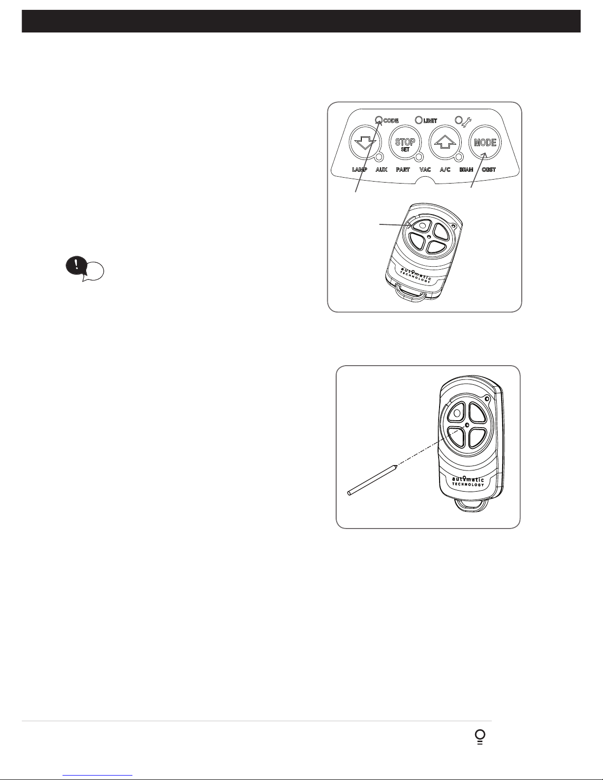
a. Press the MODE button to highlight the CODE LED.
b. Press OPEN or CLOSE buton until BLUE CLOSE, RED STOP/
SET and GREEN OPEN LEDs are on.
c. Press and hold the STOP / SET button to enter the code set
procedure (Fig. 6.6.1).
d. Press the transmitter button you wish to use to operate the
door opener (e.g. button 1) and hold for 2 seconds then
release.
e. Press the same transmitter button again and hold for seconds,
then release.
f. Release the STOP / SET button.
6.6.2 Erasing Programmed Codes
If the GREEN OPEN button is held down on power up it will clear
the the transmitter memory. (As the button is being held the
CODE LED will flash).
Fig 6.6.1
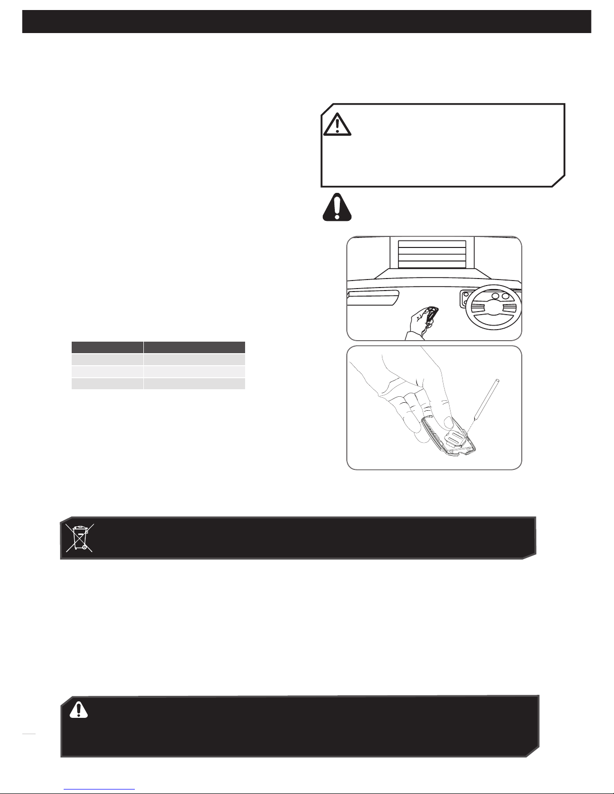
If a transmitter is already coded into the opener, additional
transmitters can be coded without being in direct contact with
the opener’s wall console unit.
NOTE: Only the function of the existing transmitter button can
be assigned to new transmitter. Please read instructions prior to
proceeding - there is a time-out facility for security reasons.
6.6.3 Selecting The Function To Be Coded
a. Using the existing transmitter, operate the Door with the
transmitter button which has the function to be coded (e.g.
Button 1 has been coded with the OSC function assigned).
b. If the button’s function activates the Door (PART, OSC, CLS,
STP or OPN) wait for the Door to complete its cycle.
6.6.4 Activate Remote Code Set Mode
a. Use a small pin / pen to press and hold through the Coding
Hole of the existing transmitter for 2 seconds (Fig. 6.6.2).
b. Within 10 seconds, press the button on the new transmitter
you wish to code for 2 seconds.
c. Press the same button again (within 10 seconds) for
confirmation.
d. Test Operation. The new transmitter button should now
function as the existing transmitter.
NOTE: To code other buttons from an existing transmitter, repeat
process pressing the button your wish to replicate.
Existing
transmitter
Fig 6.6.2
MODE
Button 1
CODE LED
HELPFUL TIP: Refer to Appendix for Additional
Transmitter coding functions
tip

14
GDO-12V1 Hiro™ Installation Instructions
IMPORTANT SAFETY INSTRUCTIONS
WARNING! TO REDUCE THE RISK OF SEVERE INJURY OR DEATH:
(1) READ AND FOLLOW ALL INSTALLATION INSTRUCTIONS.
(2) NEVER LET CHILDREN OPERATE OR PLAY WITH DOOR CONTROLS. KEEP THE REMOTE CONTROL AWAY FROM
CHILDREN.
(3) ALWAYS KEEP THE MOVING DOOR IN SIGHT AND AWAY FROM PEOPLE AND OBJECTS UNTIL IT IS COMPLETELY
CLOSED. NO ONE SHOULD CROSS THE PATH OF THE MOVING DOOR.
(4) NEVER GO UNDER A STOPPED, PARTIALLY OPEN DOOR.
(5) TEST DOOR OPENER MONTHLY. THE GARAGE DOOR MUST REVERSE ON CONTACT WITH A 1-1/2-INCH HIGH
OBJECT (OR A 2 BY 4 BOARD LAID FLAT) ON THE FLOOR. AFTER ADJUSTING EITHER THE FORCE OR THE LIMIT
OF TRAVEL, RETEST THE DOOR OPENER. FAILURE TO ADJUST THE OPENER PROPERLY INCREASES THE RISK OF
SEVERE INJURY OR DEATH.
(6) FOR PRODUCTS HAVING AN EMERGENCY RELEASE, WHEN POSSIBLE, USE THE EMERGENCY RELEASE ONLY
WHEN THE DOOR IS CLOSED. USE CAUTION WHEN USING THIS RELEASE WITH THE DOOR OPEN. WEAK OR
BROKEN SPRINGS ARE CAPABLE OF INCREASING THE RATE OF DOOR CLOSURE AND INCREASING THE RISK
OF SEVERE INJURY OR DEATH.
(7) KEEP GARAGE DOORS PROPERLY BALANCED. SEE OWNER’S MANUAL. AN IMPROPERLY BALANCED DOOR
INCREASES THE RISK OF SEVERE INJURY OR DEATH. HAVE A QUALIFIED SERVICE PERSON MAKE REPAIRS TO
CABLES, SPRING ASSEMBLIES, AND OTHER HARDWARE.
(8) EXCEPT FOR MODEL AM800, THIS OPERATOR SYSTEM IS EQUIPPED WITH AN UNATTENDED OPERATION
FEATURE. THE DOOR COULD MOVE UNEXPECTEDLY. NO ONE SHOULD CROSS THE PATH OF THE MOVING
DOOR.
(9) SAVE THESE INSTRUCTIONS.
7. Operation Instructions
Installation Instructions GDO-12V1 Hiro
™
15
CAUTION: Activate the operator only when the
door is in full view, free of obstructions and
with the operator properly adjusted. No one
should enter or leave the garage while the door
is in motion. Do not allow children to play near
the door.
Fig.7.1.1
7.1 How to Use Your Opener
For maximum efficiency of your operator, your garage door
must be in good operating condition.
An annual service of your garage door by door professional
is recommended.
REPLACE WITH BATTERY CR2032
Fig.7.1.2
7.1.1 To Operate the opener:
a. Press the programmed transmitter button until your door
begins to move (usually 2 seconds). Make sure you can
see the door when you use the transmitter (Fig 7.1.1).
b. If you are in a vehicle you should aim the transmitter
through your windscreen as shown.
c. Check that the door is fully open or closed before you
drive in or away.
d. If you press the transmitter whilst the door is moving the
door will stop. The next press of the transmitter will move
the door in the opposite direction.
7.1.2 Replacing the Battery: 3V Lithium Battery
CR2032.
a. To test the battery is working, press and hold a transmitter
button. Check Light Status table to determine if battery
needs replacing
Light Status Battery Status
Solid OK
Flashing Requires replacement
No light Requires replacement
b. Remove screw from back of cover.
c. Use screw driver to separate the transmitter casing to
expose circuit board.
d. Use a non-metallic object (e.g. pen) to remove the battery.
(Fig. 7.1.2).
7.1.3 Battery Disposal
When batteries reach the end of their usual life in accordance with Australian Battery Recycling Initiative please follow the
next simple steps for protecting the environment. Refer to the Automatic Technology website for information on where to
recycle batteries in Australia.
DO NOT throw the batteries in municipal waste. This symbol of the crossed out wheeled bin indicates
that the battery should not be placed in the municipal waste. Check your local regulations for appropriate
disposal of the batteries.
Recycling all batteries will have other environmental and social benefits:
WARNING! Prior to disposal, recycling, or collection, all battery terminals must be securely
insulated with a non conductive material to prevent any two batteries from short circuiting
and generating heat during storage or transport. Battery terminals may be insulated with
electrical tape; or batteries may be individually packaged in a non conductive material
(e.g., plastic bag or original packaging).
• Some batteries are less toxic but hazardous for other reasons. Lithium batteries can explode or catch fire in landfill,
while button cells are dangerous if swallowed by children. Recycling offers a safe and environmentally responsible
solution for end of life batteries.
• Battery recycling recovers non-renewable materials such as lead, cadmium, stella, zinc, manganese, cobalt, silver,
plastics and rare earth elements.
• Removal of batteries and other hazardous household products from household waste facilitates the recovery of
organic materials through alternative waste technologies such as composting. Batteries and heavy metals are known
contaminants in compost.
• The community supports recycling because it reduces waste to landfill and achieves environmental benefits.
WARNING! This operator has a grounding
type plug and there are no user serviceable
parts inside this operator.

16
GDO-12V1 Hiro™ Installation Instructions
7.3 Door Status Indicators
Door Status Indicators OPEN LED (green) CLOSE LED (blue) STOP (red)
Open On
Close On
Opening Flashing
Closing Flashing
Door travel stopped Flashing Flashing Flashing
Door obstructed when opening Flashing On and door will stop
Door obstructed when closing Flashing Beeps while door is moving
Opener overloaded Alternating flashes Alternating flashes
Mains power interrupted Rapid flashes
HELPFUL TIP: Refer to Appendix C for Additional
LED Indicators
tip
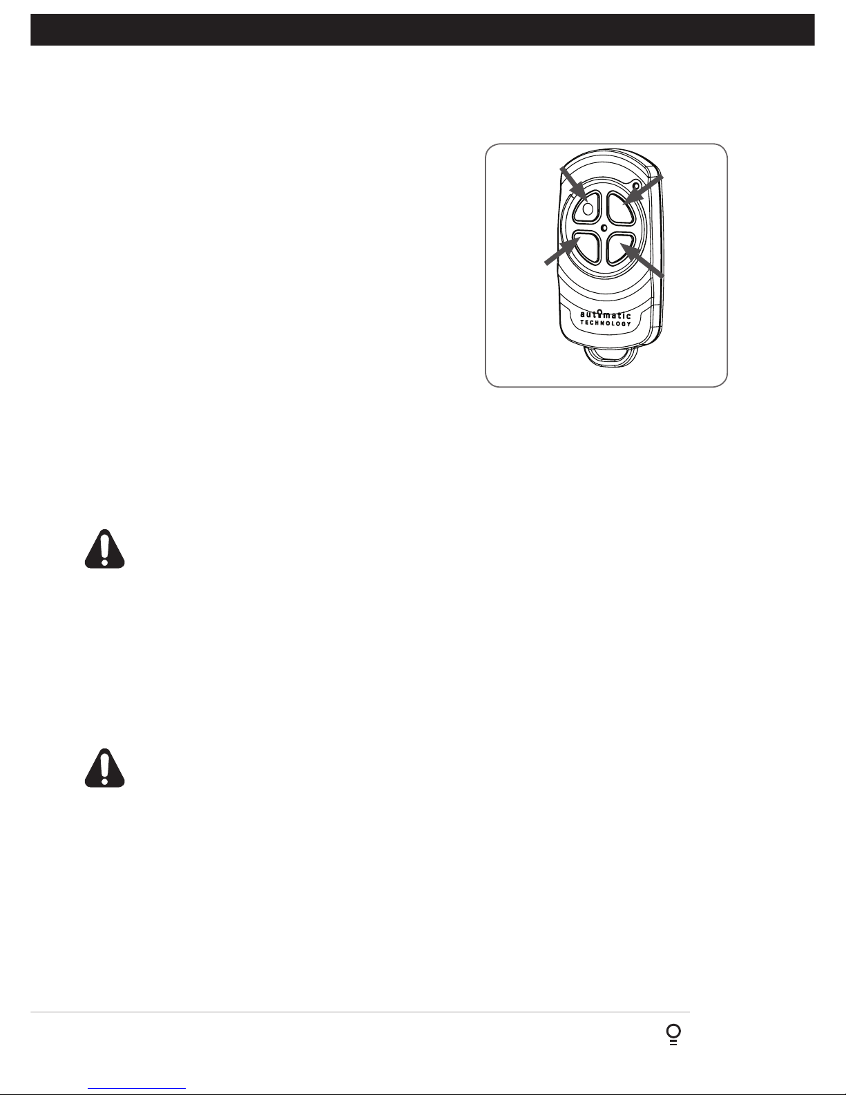
7.2 User Operating Controls
Button Function
1. BLUE DOWN ARROW Close Button
2. RED STOP/SET Stop / Set Button
3. GREEN UP ARROW Open Button
4. MODE Mode Selection Button
1 2 3 4
Installation Instructions GDO-12V1 Hiro
™
17
8. Maintenance
8.1 Door Maintenance
A poorly maintained door could cause fatal / serious injuries or
damage to property.
• Frequently examine the door, particularly the cables, springs
and mountings for signs of wear, damage or imbalance.
DO NOT USE if repair or adjustment is needed since a fault
in the installation or an incorrectly balanced door may cause
injury.
• Fasterners: Check all screws, nuts and bolts to ensure they are
secure.
• Spring Tension: It is natural for springs to lose tension. Should
the door become hard to operate or completely inoperative,
contact a door professional.
• Guide Tracks: Clean the internal sections of the guide tracks
every 3 - 6 months with a cloth dampened with mineral turps
or methylated spirits.
8.2 Service Counter
The opener has an inbuilt service counter which indicates the unit
has completed 3000 drive cycles.
By Holding the RED STOP / SET Button when the SPANNER LED
is illuminated and the main light flashes five (5) times will reset the
counter.
DO NOT DO IT YOURSELF:
WARNING! Failure to maintain your garage
door may void the warranty on your garage
door opener.
DIY
Door adjustments should only be carried
out by experienced persons, as this function
can be dangerous if not performed under
strict safety procedures.
Run the Safety Testing procedures
MONTHLY in Section 6.5 to ensure
garage door is fit for use.
tip

18
GDO-12V1 Hiro™ Installation Instructions
Symptom Possible cause Remedy
The opener does not work
from the transmitter
Garage door in poor condition e.g.
springs may be broken
The opener does not have power
The battery in the transmitter is flat
The opener has been put into
“Vacation Mode”
The transmitter button is not
programmed to operate the door.
Door Code LED is flashing yet the
opener is not working.
Check the door’s operation - see monthly
maintenance (Section 8)
Plug a device of similar voltage (e.g. a
hairdryer) into the power point and check that
it is OK
Replace the battery (Section 7.1.2)
Turn off “Vacation Mode”
(Appendix E, Vacation Mode step E.5)
See coding transmitter procedure (Section 6.6)
Ensure the correct button on the transmitter is
being pressed.
The motor is running
but the door remains
stationary
The opener is disengaged Re-engage the opener
(Section 5)
The transmitter range
varies or is restricted
Variations are normal depending
on conditions e.g. temperature or
external interference
The battery life is exhausted
Position of the transmitter in the motor
vehicle
See instructions for correct use of transmitter
(Section 7.1.1)
Refer to battery status (Seciton 7.1.2)
Change the position (Section 7.1)
The door reverses for no
apparent reason
This may occur occasionally from
environmental conditions such as areas
that are windy, dusty or have extreme
temperature changes.
If Safety Beams are installed they may
be partially obstructed.
Put the door into manual (Section 5, take note
of the CAUTION) and contact 1300 133 944.
Ensure the beam path is not obstructed. If
continues, contact your optional extras dealer.
The door opens but will
not close
Safety Beam (Optional Accessory) not
operating correctly
Contact your optional extras dealer for
support.
The Open (Green) LED
and Close (Blue) LED are
flashing alternatively
Opener is overloaded Discontinue use and contact
1300 133 944 for support.
The Open (Green) LED
continues to flash
Door obstructed when opening Clear away any obstructions and test door
opens correctly. (If door is damaged, contact a
door professional).
The Close (Blue) LED
continues to flash
Door obstructed when closing
Limits may be cleared
Clear away any obstructions and test door
closes correctly. (If door is damaged, contact
your dealer).
Remove all power sources. Wait till all lights
are out (10-15 secs), then reconnect power. If
Blue LED is flashing, limits are not set.
See Section 6 to set LIMITS.
9. Troubleshooting Guide

Installation Instructions GDO-12V1 Hiro
™
19
A - Adjustment Mode Parameters
10. Appendix
LED Indicators Parameter OPEN OPEN &
STOP
STOP CLOSE &
STOP
CLOSE
LAMP LED Light Time 180s 120s 60s 30s 0s
AUX LED Aux Time / Mode Toggle 60s 30s 1s Mimic Light
A/C LED A/C Function 90s 60s 30s 15s OFF
A/C & BEAM LED’S P.E A/C Function 60s 30s 15s 5s OFF
OBST LED Margin Setting 20 units 15 units 12 units 9 units 7 units
OPEN / STOP / CLOSE
LED’S
PG3 custom setting When all three lights are illuminated a custom setting is in place.
Parameters can be still adjusted to those listed above.
Changing Motor Speed
In order to change the motor speed, limits need to be cleared.
a. Press the MODE button repetitively until the LIMIT LED is
on.
b. Press OPEN or CLOSE buttons until the OPEN and CLOSE
LEDS are on. Press SET / STOP for 2 secs, beeper will
beep twice and CLOSE LED will start to flash.
c. Move the door to the half way position using the
programmed transmitter.
d. Press the MODE button to highlight the LIMIT LED.
e. Press Button 4 on the transmitter to inch the door closed.
f. While inching a press of the RED STOP / SET button on the
opener changes the speed setting as below:
(i) 1 press of SET - LOW (1 beep)
(ii) 2 press of SET - MED (2 beeps)
(iii) 3 press of SET - HIGH (3 beeps)
g. To change the motor speed for openening, press Button 1
to inch open then follow step f above.
h. Proceed to Section 6 to reset the limits via Opener or
Appendix D to set via transmitter.
Fig B.1
Adjustment Mode
Adjustments can be made to functions such as Light times, Auto Close functions etc. The below table shows the parameters
that can be altered.
a. Press and release the MODE button until the Spanner LED (Adjustment Mode) is highlighted.
b. One of the word LED’s (LAMP, AUX, etc) will highlight.
c. Use the BLUE CLOSE or GREEN OPEN buttons to move to the particular parameter.
d. Press RED STOP / SET to enter the adjustment mode.
e. The OPEN, STOP and CLOSE LEDS will now flash and indicate the parameters value as shown in table below.
f. Use the BLUE CLOSE or GREEN OPEN buttons to adjust the parameter value by one step up or down.
g. Press RED STOP / SET to save the new value or MODE to cancel the edit - flashing will stop.
h. To enter another parameter repeat from Step a.
B - Motor Speed
Appendix
MODE
Button 4
BLUE CLOSE Button
Button 1
RED STOP/SET Button
LIMIT LED

20
GDO-12V1 Hiro™ Installation Instructions
C - LED Status
Appendix
Operation indicators
The below table displays the status of
the opener when LEDs are activated.
LED Indicators Status
CODE LED Flickers with transmitter activity or indicating transmitter may not be coded to
the opener.
LIMIT LED Indicates the opener is in Limit Set Mode
SPANNER LED Indicates the opener is in Adjustment Mode
CLOSE / STOP / OPEN LED’S Indicate the door status currently in use
(except during power failure, auto-close and part open)
LAMP LED Only illuminates during the Adjustment Mode to change the light time
parameter
AUX LED Indicates the AUX output is activated, once a transmitter has been coded to
the AUX function.
PART LED Indicates the door is in one of the part open positions.
VAC LED Indicates the Vacation Mode is active
A/C LED On STEADY means the auto-close timer was paused due to the beam being blocked.
FLASHES to indicate the auto-close timer is running
BEAM LED On STEADY when a beam is blocked.
FLASHES when there is a P.E Fault
OBST LED On STEADY Obstruction was detected. If door open then obstruction was while closing and
vice versa.
FLASHES Stall / Overload detected. If door open then stall / overload while closing and
vice versa.
SPANNER LED On STEADY Indicates the service is due. Beeps three times at start of a drive cycle
MAIN LIGHT FLASHES Two flashes indicates that the battery is faulty.
Five Flashes indicates that periodic maintenance is due after 3000 drive cycles.
FLASHES
+ OBST LED
+ OPEN LED
+ CLOSE LED
+ LIMIT LED
+ CODE LED
+ OPEN & CLOSE LEDs
Indicates a fault. The details is indicated on the other LEDS.
Indicates current sensor fault
Indicates failed to profile open travel - during limit setting only
inficated failed to profile close travel - during limit setting only
indicates position wrap fault / position sensor fault
indicates memory fault
indicates direction fault
Installation Instructions GDO-12V1 Hiro
™
21
Button 1
(Inch Open)
Button 4
(Inch Close)
Button 2
(Set)
The GDO-12 HiRo™ has the ability to set travel limits using a
transmitter, allowing free movement around the garage to better
assess the desired limit positions. In order to use a transmitter,
it must first have at least one of its buttons coded to the door
controller. The function assigned to the transmitter’s buttons is of
no concern here as the buttons are temporally assigned to OPEN,
SET, CHANGE DIRECTION and CLOSE (Fig. D.1).
D.1 Code A Transmitter For Limit Setting
Navigating to “Code” menu
a. Press the MODE button to highlight the CODE LED.
b. Press and hold the RED STOP / SET button to enter the code
set procedure.
Storing Transmitter Code
c. Press the transmitter button you wish to use to operate the door
opener (e.g. button 1) and hold for 2 seconds then release.
d. Press the same transmitter button again and hold for seconds,
then release.
e. Release the RED STOP/SET button.
D.2 Setting Limits Via Transmitter
a. Press and hold Button 4 on the transmitter to close the door
(i) If the door opens, release Button 4 and press Button 3 to change
the direction of the motor.
WARNING! In setting the close limit position, do not
force the door into the floor with excessive force, as
this can interfere with the ease of operation of the
manual release mechanism.
b. Then press and hold Button 4 on the transmitter to close the
door.
(i) If the door is closed too far, press Button 1 to “inch” the door
towards open.
(ii) When happy with the close limit position, press Button 2 to store
this in the memory. The open green LED will starts to flash.
c. Press Button 1 to open the door.
(i) If the door is opened too far, press Button 4 to “inch” the door
towards close
WARNING: The door will automatically close and open
once next step is performed. Ensure that no persons
or objects are in the door’s path.
When happy with the open limit position, press Button 2 on the
transmitter to store into memory. The door will now automatically
close and open to calculate the safety obstruction settings.
NOTE: The openers motor speed can be adjusted during limit
setting. See Appendix B for changing motor speed.
Fig D.1
Button 3
(Change
Direction)
D - Setting Limits via Transmitter
Appendix

22
GDO-12V1 Hiro™ Installation Instructions
Fig E.1
Operate
Door
Vacation
Mode
Light
PART
Open
E.1 Transmitter Button to the Courtesy Light
The transmitter can be programmed to operate the courtesy light on
the opener independently of the door moving.
a. Press the MODE button to highlight the CODE LED if not already
highlighted.
b. Use the BLUE CLOSE or GREEN OPEN buttons to scroll through
to highlight the LIGHT LED.
c. Press and hold the RED STOP/SET button.
d. Press one of the four buttons on the transmitter for two (2) seconds,
pause for two (2) seconds, then press the same button again for
two (2) seconds.
e. Release the RED STOP/SET button.
f. Press the transmitter button to test.
E.2 Transmitter Button to enable AUX Output
The auxiliary output can be used to control alarm or another garage
door opener. This function requires a professional to wire the
accessory to the AUX Output before using the below step to code in
the transmitter.
a. Press the MODE button to highlight the CODE LED if not already
highlighted.
b. Use the BLUE CLOSE or GREEN OPEN buttons to scroll through
to highlight the AUX LED.
c. Press and hold the RED STOP/SET button.
d. Press one of the four buttons on the transmitter for two (2) seconds,
pause for two (2) seconds, then press the same button again for
two (2) seconds.
e. Release the RED STOP/SET button.
f. Press the transmitter button to test.
E.3 Transmitter Button to Operate PART (Partial) Mode
The PART mode position (see 11. Setting Partial Open Position) must
set prior to coding a transmitter.
a. Press the MODE button to highlight the CODE LED if not already
highlighted.
b. Use the BLUE CLOSE or GREEN OPEN buttons to scroll through
to highlight the PET LED.
c. Press and hold the RED STOP/SET button.
d. Press one of the four buttons on the transmitter for two (2) seconds,
pause for two (2) seconds, then press the same button again for
two (2) seconds.
e. Release the RED STOP/SET button.
f. Press the transmitter button to test.
E.4 Transmitter Button to activate Vacation Mode
The opener can be programmed into a “Vacation Mode” where the
opener will not respond to any transmitter except the button of the
transmitter that was programmed for vacation mode.
a. Press the MODE button to highlight the CODE LED if not already
highlighted.
b. Use the BLUE CLOSE or GREEN OPEN buttons to scroll through
to highlight the VAC LED.
c. Press and hold the RED STOP/SET button.
d. Press one of the four buttons on the transmitter for two (2) seconds,
pause for two (2) seconds, then press the same button again for
two (2) seconds.
e. Release the RED STOP/SET button.
f. Press the transmitter button to test.
E - Additional Transmitter Functions
Appendix
E.5 Turn Off Vacation Mode
To turn off the Vacation Mode simply press the
Vacation mode button and release.
Test that Vacation Mode is off by using another
transmitter to operate the door.

Installation Instructions GDO-12V1 Hiro
™
23
It is a condition of the below warranties that the
manual operating (opening and closing) force of the
door by hand does not exceed 20kg.
MODEL WARRANTY DOOR (MAX)
SECTIONAL
GDO-9V2 7 yrs / 20,000 cycles 200kg
GDO-9V3 7 yrs / 20,000 cycles 175kg
GDO-11V3 5 yrs / 10,000 cycles 110kg
ROLLING
GDO-6V3 5 yrs / 10,000 cycles 110kg
GDO-6V4 7 yrs / 20,000 cycles 110kg
GDO-8V3 2 yrs / 5,000 cycles 100kg
GDO-10V3 2 yrs / 5,000 cycles 270kg
GDO-12V1 2 yrs / 10,000 cycles 270kg
EXTRAS
TRACK ASSEMBLY
(includes all parts)
1 year
TRANSMITTERS &
ACCESSORIES
1 year
11. Warranty and Exclusion of Liability
This Warranty is given by Automatic Technology (Australia) Pty Ltd (ABN 11 007 125 368) (ATA),
6-8 Fiveways Boulevard, Keysborough 3173, 1300 769 850, sales@ata-aust.com.au.
PLEASE NOTE:
• This Warranty is in addition to any statutory, non-excludable guarantees or warranty rights and remedies under the law. See section 5 below.
• This warranty applies to the original purchaser only and may not be transferred.
• This Warranty is to be read in conjunction with the owner’s copy of the installation instruction manual.
• In this warranty, ‘ATA Representative’ means an entity authorized by ATA to service ATA products. Please check the ATA website for details.
REGISTER ONLINE TODAY!
Register your Product to take advantage of convenient service and support at www.ata-aust.com.au/register
NOTE: CONSUMABLES (eg Batteries in remote control transmitters and light
bulbs and fuses) are not covered by this warranty
1. MAKING A CLAIM
(a) The product parts in the above table should operate in accordance with the
product manual for the time period shown, provided you comply with the
manufacturer’s instructions concerning installation, operation, maintenance
and testing. Failure to do so may void all or part of this warranty.
(b) If, during the relevant warranty period, a product part in the table above
appears to contain a defect, call the retailer from whom you purchased the
product, or ATA on 03 9791 0240, and they will instruct you what to do next.
(c) You are responsible for the cost of making a claim under this Warranty.
Additional access expenses where the Product is not readily accessible must
be borne by you.
(d) If ATA or ATA’s Representative confirms the product is defective and covered
by this Warranty, ATA will repair or replace it (at ATA’s sole option) at no
cost to you. Goods presented for repair may be replaced or repaired by
refurbished goods or parts of the same type.
2. WARRANTY CONDITIONS
t is a condition of this warranty that:
(a) you provide a copy of the receipt of original purchase of the product, and
the serial number of the Product which can be found on the label adhered
to the Product.
(b) the door and opener are properly maintained by being serviced by a
qualified professional at regular, appropriate intervals. What is appropriate
may vary based on environmental factors (eg. weather, salt exposure) and
level of usage. Based on average use and environmental conditions, ATA
recommends that the product is serviced by ATA or an ATA Representative,
within 12 months of installation (to allow for new door to settle) and at
regular intervals not exceeding 2 years.
3. WARRANTY EXCLUSIONS
This warranty excludes defecrts or improper operation resulting from:
(a) excessive wear and tear that may cause the product to fail;
(b) accidental, deliberate or negligent damage or damage cause by nsects,
dirt, plants or other objects;
(c) blown fuses, electrical surges, power surges or power spikes or faulty or
unsuitable electrical wiring of structures to which the product is affixed;
(d) theft, fire, flood, rain, water, lightning, storms or any other acts of God;
(e) salt or other corrosion due to environmental conditions,
(f) any installation, configuration or use of the product contrary to the
instructions supplied with the product;
(g) maximum continuous operating time exceeding 1 minute in10 minutes;
(h) the manual operating (opening and closing) force of the door by hand
exceeding 20kg;
(i) weight exceeding amounts listed in table above;
(j) the door used with the product not being in safe working order and
condition;
(k) any modification to the product or acts of any person in respect of the
product which are not authorized by ATA; or
(l) radio or electrical interference or lack of availability of signal.
4. OTHER CONDITIONS
(a) This Warranty is not transferable.
(b) The warranty period stated in the table will not be extended for Products
or parts repaired or replaced during the relevant warranty period.
(c) Where the Product is sold by any person other than ATA, except for the
warranty set out above, such person has no authority from ATA to give
any warranty or guarantee on ATA’s behalf in addition to the warranty set
out above.
5. STATUTORY GUARANTEES OR WARRANTIES IN AUSTRALIA
If you are a consumer under the Australian Consumer Law, our goods come
with guarantees that cannot be excluded under the Australian Consumer
Law. You are entitled to a replacement or refund for a major failure and for
compensation for any other reasonably foreseeable loss or damage. You are
also entitled to have the goods repaired or replaced if the goods fail to be of
acceptable quality and the failure does not amount to a major failure.
This warranty certificate and other statements contained in this document
or other ATA documents given to you do not exclude, restrict or modify the
application of all or any of the provisions of the Australian Consumer Law.
Subject to your non-excludable rights under the Australian Consumer Law,
ATA expressly excludes any liability for consequential loss, incidental or
indirect damages (including but not limited to damages for loss of business
profits, business interruption and loss of business information) due to a
defect of the Product. In particular, any loss or damage caused to other
equipment or accessories used with the product or any loss resulting from a
delay in repair is excluded to the extent permitted by law.

24
GDO-12V1 Hiro™ Installation Instructions
© September 2018 Automatic Technology
(Australia) Pt y Ltd. All rights reserved. No part
of this document may be reproduced without
prior permission. In an ongoing commitment
to product quality we reserve the right to
change specification without notice. E&OE.
Automatic Technololgy (Australia) Pty Ltd
ABN 11 007 125 368
6-8 Fiveways Boulevard
Keysborough, Victoria, 3173, Australia
P 1300 133 944
E sales@automatictechnology.com.au
www.automatictechnology.com.au
 Loading...