

Page 1
WARNING
It is vital for the safety of persons to follow all
instructions. Failure to comply with the installation
instructions and the safety warnings may result in
serious personal injury and/or property and remote
control opener damage.
Please save these instructions for future reference.
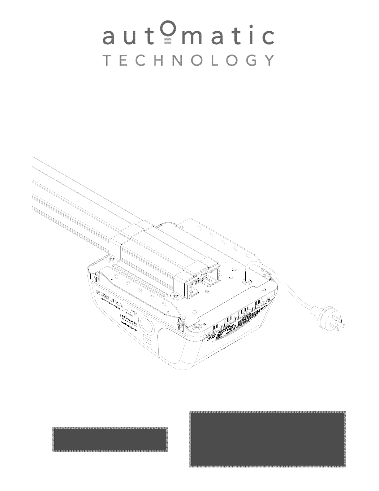
GDO-9V1 SecuraLift
®
Overhead Garage Door Opener
IInnssttaallllaattiioonn IInnssttrruuccttiioonnss
OOWWNNEERRSS CCOOPPYY
P/N 13210
Page 2
TABLE OF CONTENTS
Safety Precautions------------------------------------------------3
Opener Features----------------------------------------------------4
Operating Controls-------------------------------------------------5
Kit Contents----------------------------------------------------------7
Installation------------------------------------------------------------9
C-rail Assembly-----------------------------------------------------------9
Determine Door Type----------------------------------------------------11
Mounting - Track Type Door-------------------------------------------12
Mounting - Spring Loaded Door--------------------------------------13
Mounting Door Bracket & Arms---------------------------------------14
Easy Access Transmitter-----------------------------------------------15
Programming the Opener---------------------------------------16
Setting Travel Limits - Control Panel--------------------------------16
Setting Travel Limits - Transmitter-----------------------------------17
Safety Obstruction Force Test -------------------------------18
Coding Transmitters----------------------------------------------19
Door-------------------------------------------------------------------------19
Courtesy Light------------------------------------------------------------19
Vacation Mode------------------------------------------------------------19
Pet Mode-------------------------------------------------------------------19
Storing Transmitter From Remote Loc.-----------------------------20
Erasing Transmitter Codes---------------------------------------------20
Accessories----------------------------------------------------------21
Photo Electric Beam-----------------------------------------------------21
Auto-Close------------------------------------------------------------------21
Battery back up installation---------------------------------------------22
Final Set Up----------------------------------------------------------23
Courtesy Light Time-----------------------------------------------------23
Pet Mode Door Height--------------------------------------------------23
Transmitter Wall Bracket-----------------------------------------------23
Re-Initialising--------------------------------------------------------------23
Parameter-------------------------------------------------------------24
Door Status Indicators---------------------------------------------------24
Quick Reference Guide-------------------------------------------------24
System Specification---------------------------------------------25
Factory Default Settings------------------------------------------------25
Trouble Shooting Guide-----------------------------------------26
Maintenance Record----------------------------------------------26
Parts List--------------------------------------------------------------27
Warranty---------------------------------------------------------------28
Automatic Technology Australia Pty Ltd to the extent that such may be lawfully excluded hereby expressly disclaims all
conditions or warranties, statutory or otherwise which may be implied by laws as conditions or warranties of purchase of
an Automatic Technology Australia Pty Ltd Garage Door Opener. Automatic Technology Australia Pty Ltd hereby further
expressly excludes all or any liability for any injury, damage, cost, expense or claim whatsoever suffered by any person
as a result whether directly or indirectly from failure to install the Automatic Technology Australia Pty Ltd Garage Door
Opener in accordance with these installation instructions.
Page 3
3
SAFETY PRECAUTIONS
Warning - It is vital for the safety of persons to follow all instructions. Failure to comply
with the following Safety Rules may result in serious personal injury and/or property damage.
Caution: If your garage has no pedestrian entrance
door, an emergency access device should be
installed. This accessory allows manual operation
of the garage door from outside in case of power
failure.
For ADDITIONAL SAFETY protection we
STRONGLY recommend the fitting of a Photo
Electric Beam. In most countries Photo Electric
Beams are mandatory on all garage doors fitted
with automatic openers. For a small additional
outlay ATA recommends that Photo Electric Beams
be installed with the automatic opener ensuring
additional safety and peace of mind.
DO NOT operate the garage door opener unless
the garage door is in full view and free from objects
such as cars and children/people. Make sure that
the door has finished moving before entering or
leaving the garage.
DO NOT operate the garage door opener when
children/persons are near the door. Children must
be supervised near the garage door at all times
when the door opener is in use. SERIOUS
PERSONAL INJURY and/or property damage can
result from failure to follow this warning.
DO NOT allow children to operate the garage door
opener. SERIOUS PERSONAL INJURY and/or
property damage can result from failure to follow
this warning.
Regularly check to make sure that the SAFETY
OBSTRUCTION FORCE is working correctly, and
is TESTED (by placing a 50mm high object on the
floor) and set as per the Installation Instructions
Manual. Failure to follow the manual could result in
SERIOUS PERSONAL INJURY and/or property
damage. This test must be repeated at regular
intervals and the necessary adjustments made as
required.
DO NOT disengage the door opener to manual operation
with children/persons or any other objects including motor
vehicles within the doorway.
The door opener is not intended for use by young
children or infirm persons without adequate
supervision. Children should be supervised to
ensure that they do not play with the remote
transmitters or the opener.
Keep hands and loose clothing CLEAR of the door
and door opener at all times.
The unit should be installed so that it is protected
from the elements. It should not be exposed to
water or rain. It is not to be immersed in water or
sprayed directly by a hose or other water carrying
device.
The garage door must be WELL BALANCED.
Sticking or binding doors must be repaired by a
qualified garage door installer prior to installation of
the opener.
Frequently examine the installation, in particular
cables, springs and mountings for signs of wear,
damage or imbalance. DO NOT use if repair or
adjustment is needed since a fault in the
installation or an incorrectly balanced door may
cause injury. DO NOT attempt to repair the door
yourself as hardware is under extreme tension.
REMOVE OR DISENGAGE all garage door locks
and mechanisms prior to installation of the opener.
Connect the garage door opener to a properly
EARTHED general purpose 240V mains power
outlet installed by a qualified electrical contractor.
DISCONNECT THE POWER CORD from mains power
before making any repairs or removing covers. Only
EXPERIENCED service personnel should remove covers
from the garage door opener.
When using auto close mode, a PHOTO
ELECTRIC BEAM must be fitted correctly and
tested for operation at regular intervals. EXTREME
CAUTION is recommended when using auto close
mode. ALL SAFETY RULES must be followed.
In order for the garage door opener to SENSE an
object obstructing the door way, some FORCE
must be exerted on the object. As a result the
object, door and/or person may suffer DAMAGE or
INJURY.
If the power supply cord is damaged, it MUST be
replaced by an ATA service agent or suitably
qualified person.
Make sure that the door is fully open before driving
in or out of the garage and fully closed before
leaving the driveway.
Make sure that remote controls are kept out of
reach of children.
Install the wall switch or wall mounted transmitter in
a location where it is out of reach of children and
the garage door is visible.
Page 4

4
FEATURES
Thank you for purchasing the ATA
GDO-9 Automatic Garage Door
Opener. This opener is designed to
suit sectional overhead and one
piece tilt up doors. The components
and materials used in this opener
are of the latest technology and
highest quality. Listed below are
some of the many features.
OPERATION
To open or close the door simply
press the hand held transmitter, the
wall mounted transmitter, or optional
wall switch for two seconds. During
an open or close cycle the door can
be stopped by pressing the button
while the door is in motion. The next
actuation will move the door in the
opposite direction.
HOPPING CODE
Every time a transmission is made
from the remote transmitter a new
security code is generated. The
number of possible code
combinations is over 4.29 billion.
This greatly enhances the security
of the system. Code “grabbing” is
made a thing of the past.
ALPS ( AUTOMATIC
LIMITS POSITIONING SYSTEM)
The ALPS system does away with
manual adjustment of the doors’
limits position using mechanical
parts, such as cams and micro
switches.
During installation the hand held
transmitter can be programmed to
set the door limits positions.
ISS (INTELLIGENT SAFETY
OBSTRUCTION SYSTEM)
Whilst performing a close cycle the
door will automatically reverse if it
should hit an obstacle or is restricted in some manner. The amount of
force the door should encounter
before reversing is automatically
adjusted by the control system during the initialisation of the opener.
The door will also stop if restricted
whilst opening. The safety obstruction force should be checked at
least once a month. See installation
manual for instructions.
SECURITY CODE STORE
The gdo-9 securalift® Garage Door
Opener uses state of the art technology in storing your selected
transmitter security codes Up to 24
different transmitters can be stored
in the openers memory.
OVER LOAD INDICATOR
When the maximum opening and
closing capacity of the opener is
exceeded an audible beeper will
sound to indicate that an overload
has occurred.
AUTO COURTESY LIGHT
The opener’s courtesy light illuminates automatically whenever the
door is activated. The light can
also be switched on and off without
operating the door. This is done by
pressing the button on any transmitter which has been coded to operate
the light. The light will stay on for
approximately three minutes then
switch off. This time is also
adjustable.
BATTERY BACK UP (OPTIONAL)
The opener has provision to include
a battery back up module. This is an
ideal addition if the garage door is
the only entrance to the garage or if
the area is prone to power cuts.
Note: If the panel lift door is the only
entrance to the garage and a battery
back up kit is not fitted to the opener - a keyed cable release should be
fitted to the exterior of the garage.
VACATION MODE
A transmitter can be programmed to
block out all other transmitters that
have been programmed into the
opener’s memory. Vacation mode is
ideal for homes with non-permanent
tenancy or when the door is to be
left idle for long periods of time.
PET (PEDESTRIAN) MODE
A transmitter can be programmed to
open the door partially so that the
family pet can enter and exit the
garage at any time. If required, you
may also wish to open the door to a
height suitable only for pedestrian
access. The opening height is
adjustable.
AUTO CLOSE MODE
The opener can be programmed to
automatically close after an open
cycle. It is compulsory to install a
photo electric beam if this mode is
selected, otherwise the door may
cause personal injury or damage to
property. Auto close time is
adjustable.
PHOTO ELECTRIC BEAM
(OPTIONAL)
The opener has an input for a photo
electric beam to be connected for
extra safety protection and use of
the auto close mode.
MANUAL OPERATION
The opener is equipped with a
unique manual disengaging device.
If the power to the opener is
disrupted for any reason the door
can be put into manual mode by
pulling down on the string handle on
an angle towards the door. This will
allow you to manually open or close
the door. To re-engage the opener
pull the string handle away from the
door.
EASY ACCESS TRANSMITTER
Inside the manual release handle is
a transmitter designed to be in easy
reach so that the garage door can
be operated without having to
stretch to reach the oprate button on
the control panel.
Page 5

5
OPERATING CONTROLS
1. P. E. SHUNT. The shunt has to
be removed when connecting a
Photo Electric Beam.
NOTE: P.E. SHUNT must not be
removed otherwise the opener will
not function correctly. Remove only
when a P.E beam is to be
connected.
2. Terminal is used to connect 24vac
to the control board
3. 10 amps fuse is to protect
the electronic circuit board
4. this connector is used to connect
battery charger sby3 to the opener
5. dc 24v motor connects to this
connector.
6. OPERATE (YELLOW) button is
used during installation to test the
open, stop and close cycles for the
opener. The opener has to be
initialised by the Reset button
before the oprate button becomes
operable.
7. PLUS (
+ ) (GREEN) button is
used During installation to help set
the open limit position. Pressing and
holding this button will move the
door in the open direction.
Movement stops when the button is
released.
8. PROG INPUT is used for the
connection of the ATA Handheld
Programmer for the purpose of
editing control and receiver
functions.
9. LED light module connector is
used to connect 24v led light
module
10. FORCE MARGIN SET Button
The obstruction force pressure is
set automatically by the opener
during installation. The pressure can
be adjusted manually using the
Force Margin Set button . Holding
the Force Margin Set button and
pressing the Plus (+) or Minus
(-) button will increase or decrease
the amount of force. The Force
Margin Set is only ever used if other
environmental factors (wind, etc.)
effect the operations of the
door/opener.
11. OPEN LIMIT LED (green) the
led is very helpful during installation.
It illuminates and flashes when the
door is opening and remains steady
on when the open limit position has
been reached.
12. AUTO CLOSE TIME button is
used to adjust the auto close time.
While holding in the auto close button and then pressing the open button the time is increased. Each
press will increase the time by 5
seconds. Pressing the close
button will decrease the time.
13. CLOSE LIMIT LED (red) the led
is very helpful during installation. It
illuminates and flashes when the
door is closing and remains steady
on when the close limit position has
been reached.
14. MINUS (-) (RED) button is used
during installation to help set the
close limit position. Pressing and
holding this button will move the
door in the close direction.
Movement stops when the button is
released.
15. DOOR STATUS LED (Yellow)
16. DOOR CODE (BLUE)button is
used for storing or erasing the
transmitter button you wish to use to
command the door to open, stop or
close.
17. CODING LED light flashes
when a code is being stored or
when a transmitter button is
pressed.
18. LIGHT CODE button is used for
storing or erasing the
transmitter button (code) you wish
to use to switch the courtesy light on
the opener on or off.
19. SET (ORANGE) button is used
during the installation phase together with the Open and Close buttons
to set the door limit positions. The
Set button is also used to re-initialise the Opener.
20. .
Terminal Block. 24V PWR is used
to power devices such as photo
electric beams.
PE (Input) for photo electric beam
for safety and auto-close function.
LGT (Input) allow hard wired
external trigger for the opener’s
courtesy light.
O/S/C INPUT is used for the
connection of a wired switch
(momentary contact). This switch
can then be used to open, stop or
close the door. Install the wall switch
in a location where the switch is out
of reach of children and the garage
door is visible.
Page 6
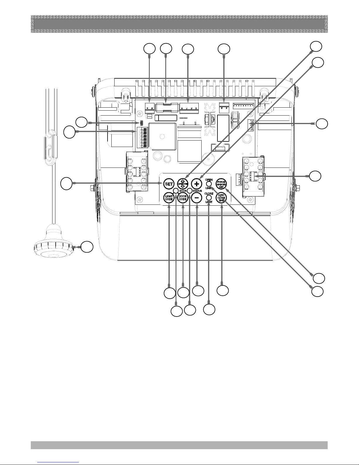
1) P.E. SHUNT
2) 24V POWER INPUT CONNECTOR
3) 10 AMP FUSE
4) SBY-3 BATTERY BACK UP CONNECTOR
5) MOTOR CONNECTOR
6) OPERATE (YELLOW) BUTTON
7) PLUS (+) (GREEN) BUTTON
8) PG-3 PROGRAMMER CONNECTOR
9) COURTESY LIGHT MODULE
10) FORCE MARGIN BUTTON
11) OPEN LIMIT LED
12) AUTO CLOSE TIME BUTTON
13) CLOSE LIMIT LED
14) MINUS ( - ) (RED) BUTTON
15) STATUS LED
16) DOOR CODE (BLUE) BUTTON
17) CODE SET LED
18) LIGHT CODE BUTTON
19) EASY ACCESS TRANSMITTER
20) SET (ORANGE) BUTTON
21) PE, O/S/C CONNECTOR
20
16
14
15
19
17
13
12
18
2
3
4
5
6
7
8
9
10
11
1
OPERATING CONTROLS
6
FIG. 1
21
Page 7
7
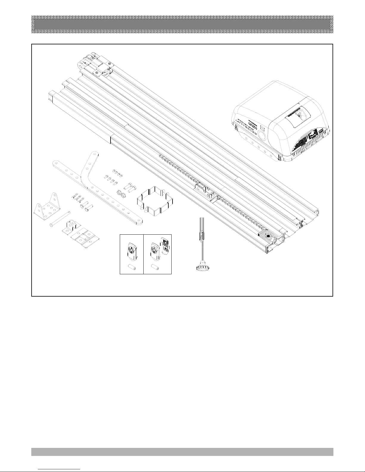
ITEM QUANTITY
GDO-9 SECTIONAL DOOR OPENER DRIVE UNIT------------------------------------------------------1
EASY ACCESS TRANSMITTER EAT-1 (NOT INCLUDED IN SOME MODELS) -----------------1
KEY RING TRANSMITTER PTX-4 PACK--------------------------------------------------------------------1
(pack includes two keyring transmitters two batteries and one wall mount bracket for ptx4 transmitter)
C-RAIL PACK--------------------------------------------------------------------------------------------------------1
DOOR ATTACHMENT ARMS------------------------------------------------------------------------------------2
ACCESSORY PACK------------------------------------------------------------------------------------------------1
INSTALLATION MANUAL-----------------------------------------------------------------------------------------1
KIT CONTENTS
GDO-9V1 AUTO OPENER CH P/N 00090
FIG. 2
Page 8
KIT CONTENTS
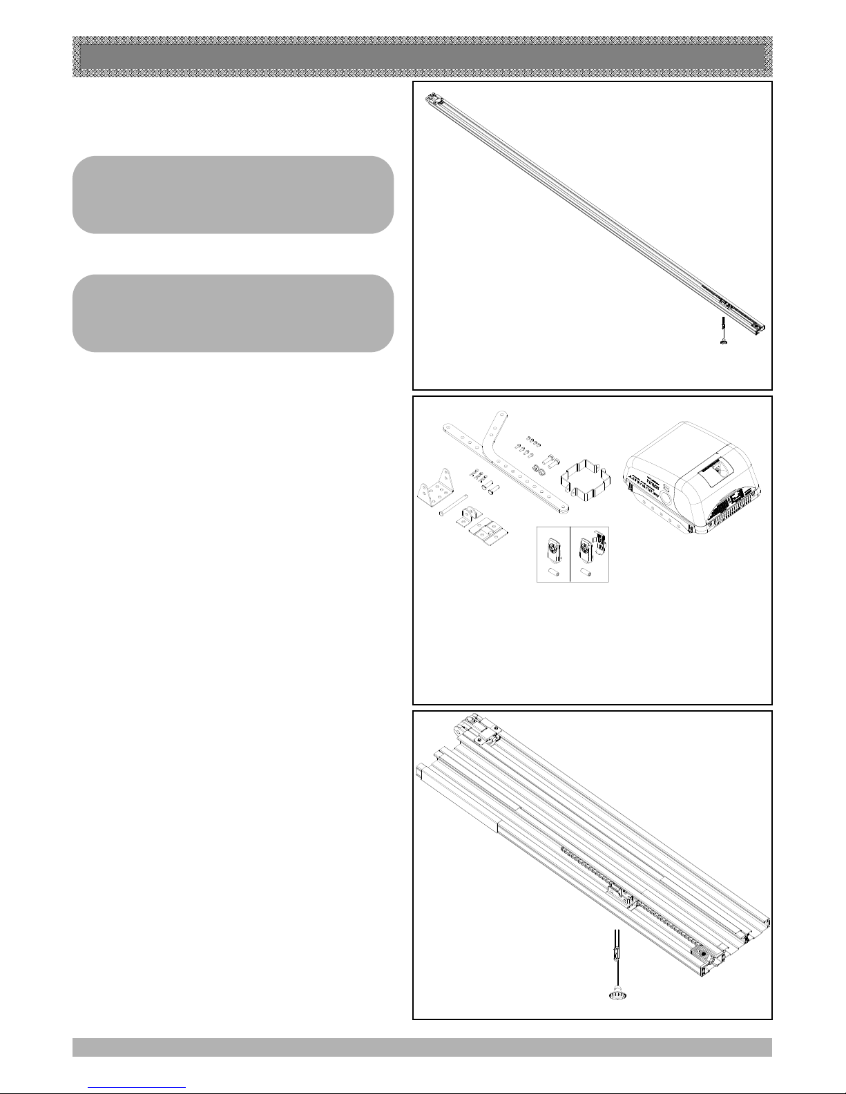
ITEMS QTY
one piece c-rail assembly 1
See fig 3
C-RAIL CH-1P VP1 ASSY
P/N 01651
C-RAIL CH-1P VP1 ASSY
P/N 01651
C-RAIL CH-KD
3P VP1 ASSY
P/N 01650
ITEMS
QTY
GDO-9 SECTIONAL DOOR OPENER DRIVE UNIT---1
KEY RING TRANSMITTER PTX-4 PACK----------------1
(pack includes two keyring transmitters two
batteries and one wall mount bracket for ptx4 transmitter)
DOOR ATTACHMENT ARMS--------------------------------2
ACCESSORY PACK--------------------------------------------1
ITEMS QTY
C-Rail knock down assembly---------------1
FIG. 3
FIG. 4
FIG. 5
See fig 4
See fig 5
8
Note
chain in one piece rail has been tensioned by
the factory
Do not adjust the tension of the chain
IMPORTANT NOTE
If modification to the track length
required,adjustment must be made only from
power head side.
Page 9
9
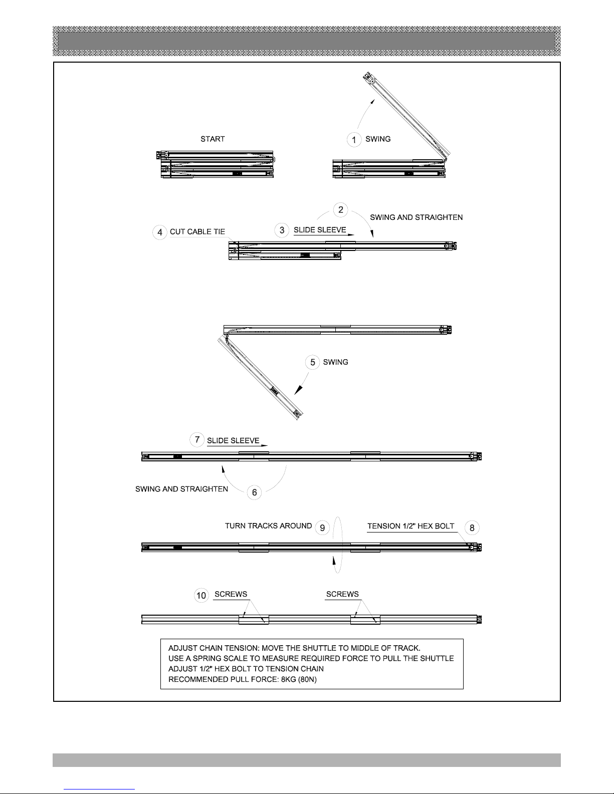
Step 1
Unpack and assemble the C -rail as shown above in fig 6
C-RAIL ASSEMBLY
FIG. 6
Page 10
C-RAIL ASSEMBLY
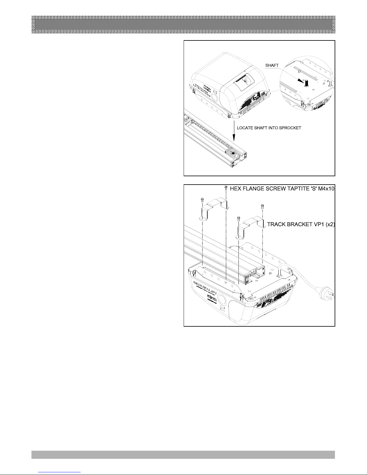
Step 2
Locate and insert the shaft of drive unit into
sprocket as shown in fig 7
Step 3
Fix the two track brackets as shown in fig 8
fix with four screws supplied in accessory pack
FIG. 7
FIG. 8
10
Page 11
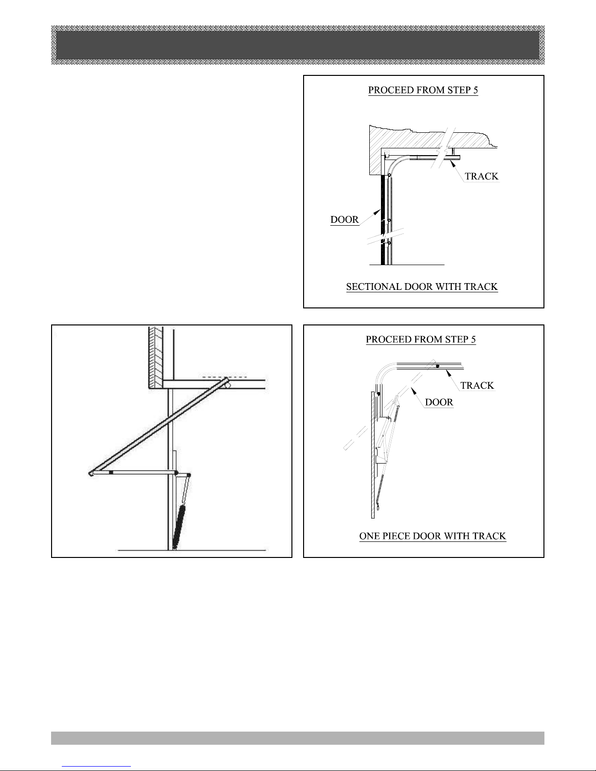
DETERMINE THE DOOR TYPE
Step 4
Determine which type of garage door you have as illustrated below. (Fig. 9 - 11).
l For a sectional (panel) door on tracks (Fig. 9) proceed with
the installation from Step 5.
l For a one piece door on tracks (Fig. 10) proceed with the
installation from Step 5.
l For a one piece door without tracks (on springs) (Fig. 11)
proceed with the installation from Step 9.page 13
11
one piece door
without track
FIG. 11
FIG. 10
FIG. 9
Page 12
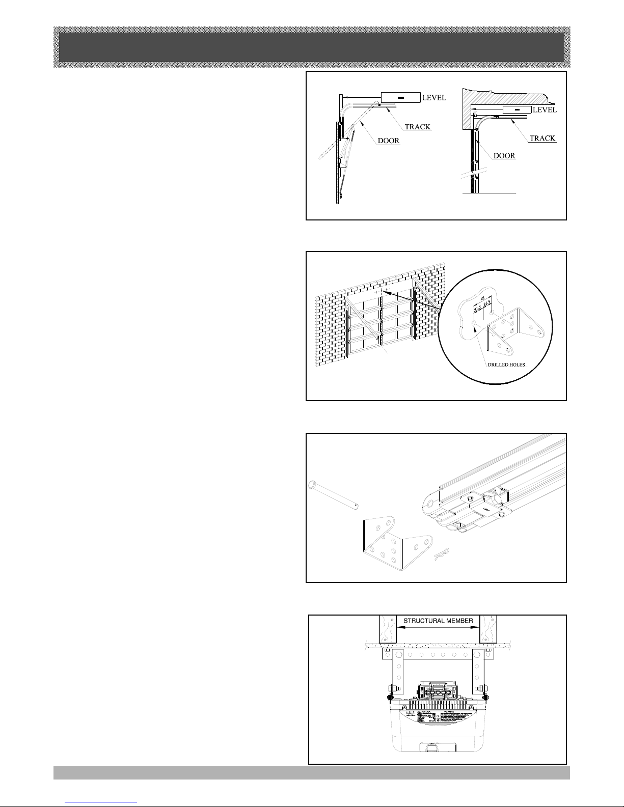
STEP 5
Open the door and find the highest point of travel of the
top door panel. Using a level, transfer this height to the
wall above the door (Fig. 12) and mark a line 60mm
above it.
Determine the centre point on the wall above and on top
of the door. Then draw two (2) lines 21.5mm on each
side of the centre point. (Fig. 13).
STEP 6
The wall bracket should be mounted 60mm above
highest point of the doors travel, 21.5mm from the
centre point. (Fig. 13).
If the wall bracket is mounted onto concrete or brick wall,
use 8mm or 5/6 loxins or dynabolts. If mounting onto
wooden lintel or beam, use wood screw #20 or
equivalent minimum 50mm long.
WARNING: MAKE SURE CONCRETE, BRICK WALL
OR TIMBER LINTEL ARE SOLID AND SOUND SO AS
TO FORM A SECURE MOUNTING PLATFORM.
STEP 7
When the wall bracket is firmly secured in its proper
position, attach the support c-rail assembly to wall
bracket with 90mm long clevis pin and secure with
supplied snap pin, (Fig. 14) leaving drive unit in its
packing box for protection during installation.
STEP 8
Raise the drive unit from the packing box and support it
in a horizontal position with a step ladder, then open the
garage door. Rest the opener on the open door and use
a scrap piece of wood to bring it to horizontal level. Line
up the track perpendicular to the wall.
Secure to the ceiling above drive unit mounting holes,
with perforated angle (not supplied). A representative
mounting is shown. (Fig. 15)
Connect angle and drive unit with two flat perforated
strips of angle (not supplied) with M8 x 20mm screws,
and nuts . Strips should not extend more than 18mm
below centre of drive unit mounting holes. (FIG. 15).
WARNING: THE OPENER MUST BE SECURELY
FASTENED TO A STRUCTURAL SUPPORT OF THE
GARAGE. FAILURE TO FASTEN THE OPERATOR
CORRECTLY MAY LEAD TO OPENER FAILURE
CAUSING SERIOUS PERSONAL INJURY AND/OR
PROPERTY DAMAGE.
MOUNTING OPENER FOR TRACK TYPE DOOR
12
FIG. 12
FIG. 13
FIG. 14
FIG. 15
Page 13
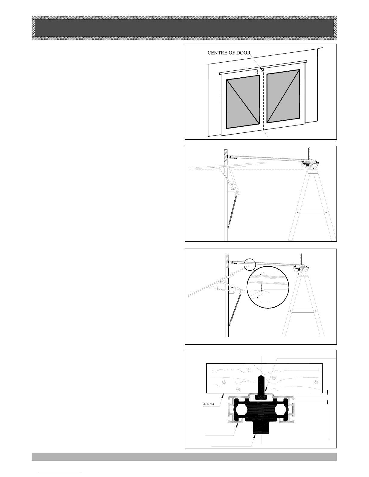
MOUNTING OPENER FOR SPRING LOADED DOOR
STEP 9
Determine the centre of the door and mark this location
on the wall above and on top of the door. Then draw two
(2) lines 21.5mm on each side of the centre point.
(Fig. 16).
WARNING: MAKE SURE CONCRETE, BRICK WALL OR
TIMBER LINTEL ARE SOLID AND SOUND SO AS TO
FORM A SECURE MOUNTING PLATFORM.
STEP 10
Raise the door to open position. Rest the opener on the
top edge of the door with end of the c-rail against the wall
and drive unit supported level with the lowest point of the
open door.
(Fig. 17).
Note: Do not slide opener c-rail on face of the door when
it is open as it may damage the door surface.
Secure the drive unit to the ceiling with perforated angle
(not supplied). A representative mounting is shown.
(Fig. 15).
Connect angle and drive unit with two flat perforated
strips of angle (not supplied) with M8 x 20mm screws
and nuts. The strips should not extend more than 18mm
below centre of drive unit mounting holes. (Fig. 15).
Do not lock screws at this stage.
STEP 11
Close the door slowly. The opener c-rail will be
elevated by the top edge of the door as it moves. Stop the
door when it is at its highest point of travel. (Fig. 18).
Allow 25mm additional height for clearance between the
door and the track. Support c-rail in this position and then
close the door. (Fig. 18) This will be the height to mount
the wall bracket. The top of the door must not touch the
tube.
WARNING: THE OPENER MUST BE SECURELY
FASTENED TO A STRUCTURAL SUPPORT OF THE
GARAGE. FAILURE TO FASTEN THE OPERATOR CORRECTLY WILL LEAD TO POSSIBLE OPENER FAILURE
CAUSING SERIOUS PERSONAL INJURY AND/OR PROPERTY DAMAGE.
the opener can be fastened to the roof by drilling
a hole in the centre of the c-rail and driving a
bolt through it into
structural timber support. the height of bolt head
must not exceed 6 mm. see fig 18a
STEP LADDER
STEP LADDER
25mm
DOOR
C RAIL
HIGHEST POINT
OF DOOR TRAVEL
FIG. 16
FIG. 17
FIG. 18
13
6mm MAX
(HEIGHT OF BOLT HEAD)
ALUMINIUM RAIL
SHUTTLE VP2 ASSEMBLY
DRILL HOLE AT CENTER OF TRACK
(RECOMMENDED BOLT SIZE M6 OR M8)
FIG. 18A
Page 14
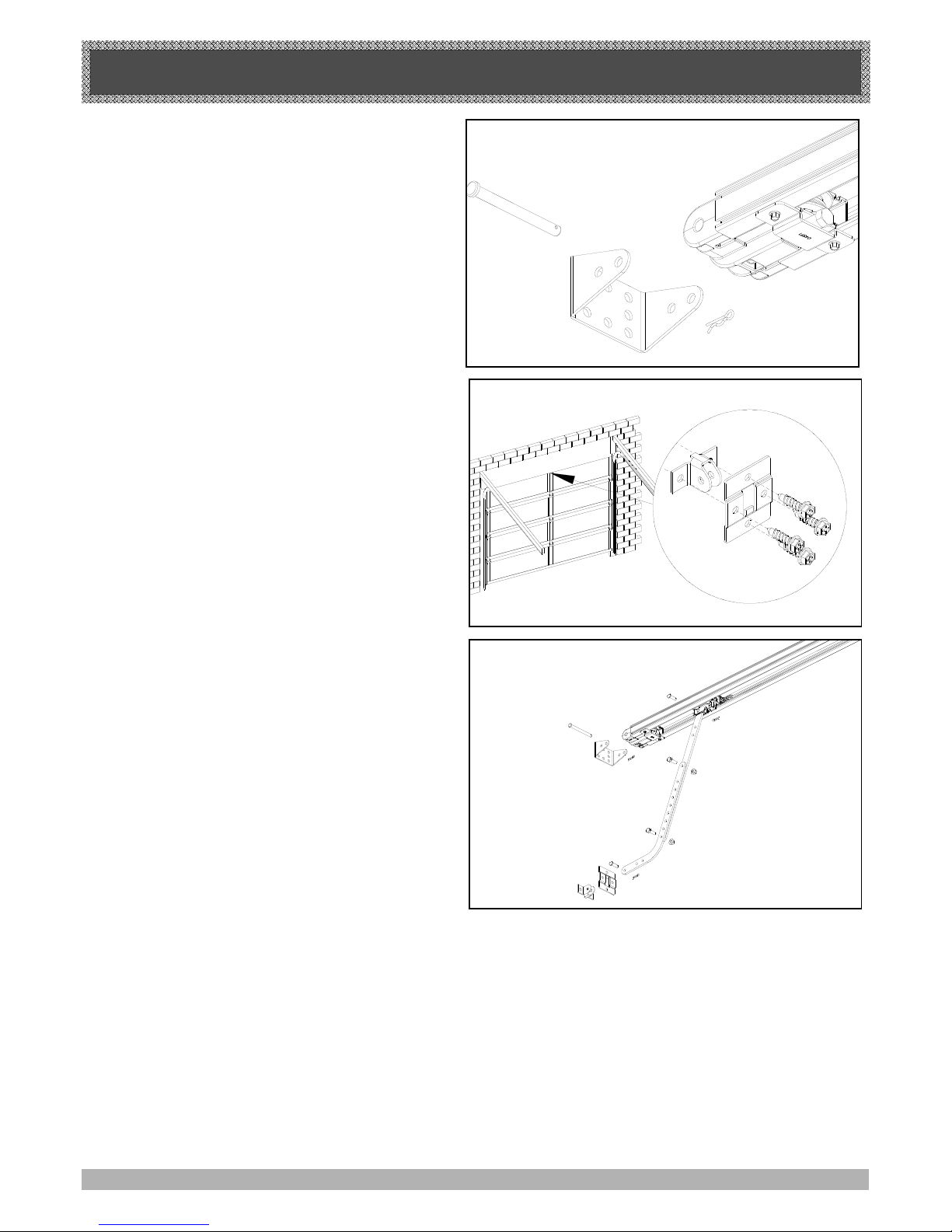
MOUNTING DOOR BRACKET AND ARMS
STEP 12
With the centre point of the door located, mark a line
through the centre of the wall bracket onto the header
wall (above the door). Using the bracket as a template
mark a minimum of two holes and drill with appropriate
size bit. If necessary the wall bracket can be anchored
using more than two holes for a more secure fitting.
If the wall bracket is mounted onto concrete or brick wall,
use M8 or 5/6 loxins or dynabolts. If mounted onto
wooden lintel or beam, use wood screws #20 or
equivalent, minimum 50mm long. Attach the wall bracket
to the c- assembly with 90mm long clevis pin (Fig. 19) and
secure by snap pin.
MOUNTING DOOR BRACKET AND ARMS
STEP 13
The door bracket comes in two parts. The bottom plate
with two mounting holes is used on its own for any one
piece doors. The top plate is placed over the bottom plate
and uses 4 mounting holes for extra strength. This is used
on sectional doors. (See Fig. 20).
Mount the door bracket to the centre line of the door
(Fig. 20), using M6 or equivalent screws (not supplied)
Alternatively it can be welded on steel doors.
Note: As various types of doors exist, if in doubt about the
strength of the door, reinforcement may need to be added
to the frame of the door panel where necessary. Damage
to the door panel may occur if the bracket is installed
incorrectly on a panel with insufficient strength. The door
opener warranty does not cover damage caused by the
opener to the door and/or door panel.
STEP 14
Assemble bent and straight arm with screws, plain and
spring washer and nuts supplied in accessory pack. (Fig.
21) Then connect assembled arm to the door bracket and
the trolley by clevis pin and snap pin. Trolley must be in
disengage position. Always use both the bent and straight
arm.
If installing on a door with bad wave action, lengthening
the arm even further will assist the door operation by
reducing the wave action.
FIG. 19
FIG. 20
FIG. 21
14
Page 15
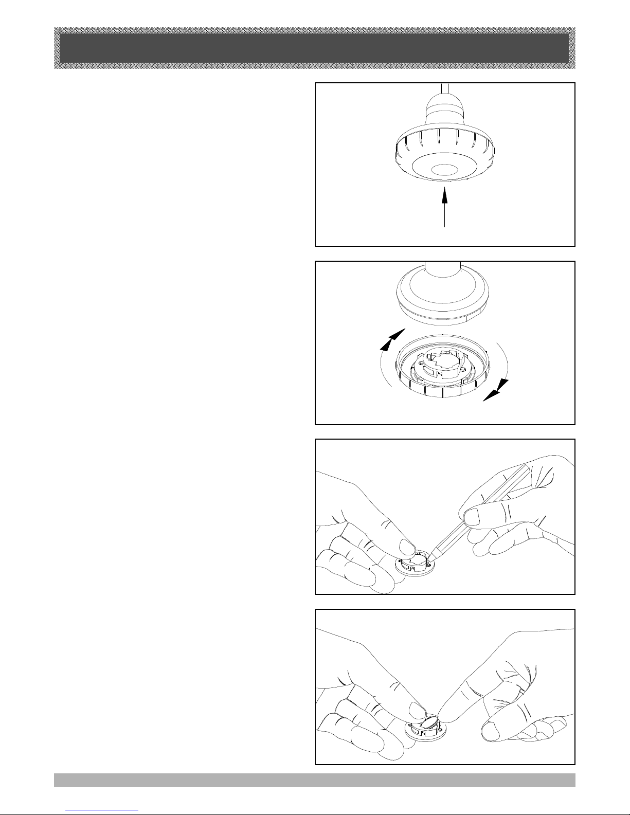
EASY ACCESS TRANSMITTER
15
PRESS BUTTON
ROTATE
FIG. 22
FIG. 23
FIG. 24
EASY ACCESS TRANSMITTER
The Easy Access Transmitter is prepared ready for use
with the battery pre-installed. Before the transmitter can
be operational, the transmitter code has to be stored into
the openers memory. To store the code refer to Step 18.1
on page 19.
REMOVING THE COVER TO REPLACE BATTERY
1. Rotate the cover Clockwise to CLOSE
2. Rotate the cover Anti-clockwise to OPEN
REMOVING THE BATTERY
(Battery Type: 3V Lithium Battery CR1220).
Use a non-metallic object (e.g pen) to remove the battery.
Gently lever the battery out of the holder, taking care to
not damage the circuit board. (Fig. 24)
WARNING
Metallic objects used to remove the battery may damage
the circuit board or the battery.
REPLACING THE BATTERY
Make sure that positive (+) side is facing up. Place one
side of the battery into the holder (Fig. 25), then press the
battery in and down firmly until it clicks into a flat position.
Note: The length of the manual release cord is user
adjustable. Simply slide the plastic toggle along the cord
to achieve the desired length. Adjust the length of the
cord so that it can be easily reached by an adult of
average height (ie. less than 1.8m tall).
FIG. 25
Note: Positive (+) side up
+
+
+
Page 16
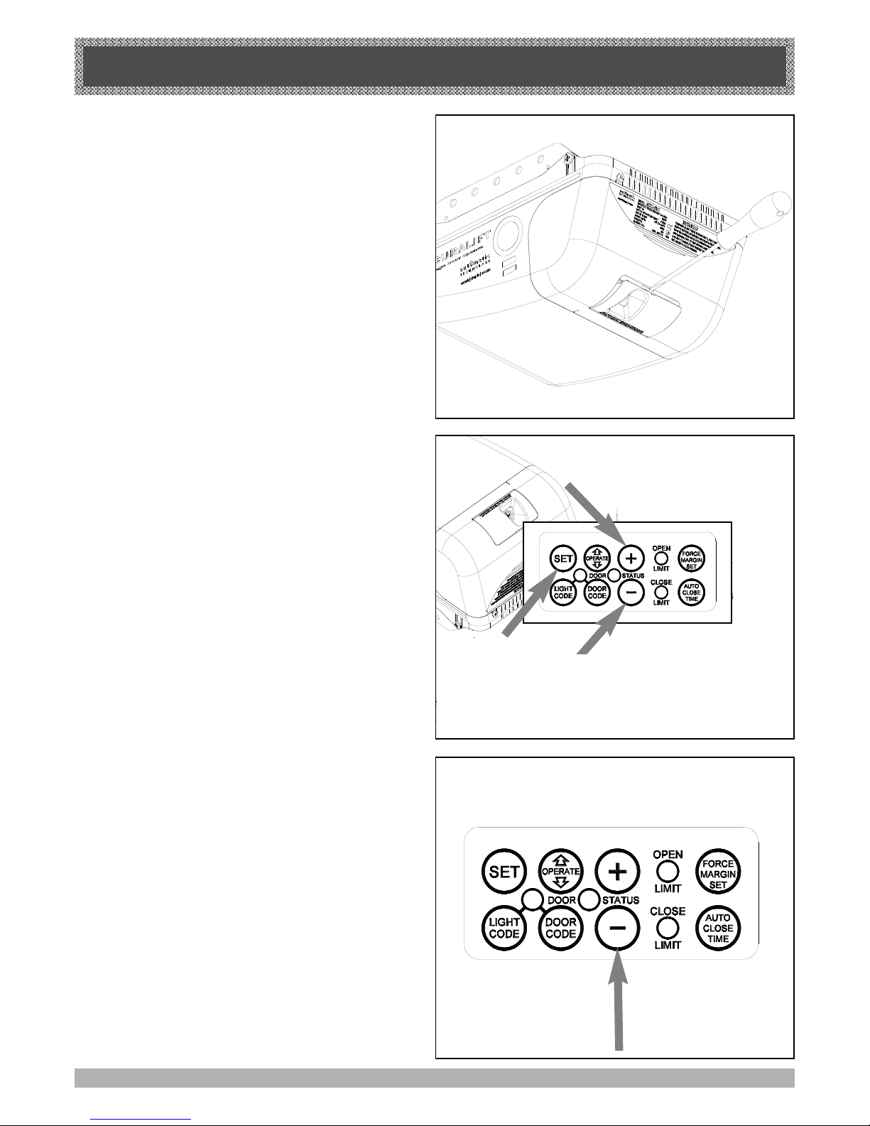
SETTING LIMITS
16
STEP 15
SETTING TRAVEL LIMITS POSITIONS
METHOD ONE: VIA THE CONTROL PANEL
IMPORTANT NOTE: The OPERATE button will not
function until the open and close limits positions are set.
Remove the controls cover to access the controls panel
as shown in fig 26
15.1 SETTING LIMITS POSITIONS
NOTE: The door and shuttle must be engaged into the
chain index and should be open approximately half way.
1. Press red Minus (-) button and hold it, the door will
start closing. Release the button once you have
reached your desired closed limit position. (Fig. 27)
2. Press the set button. This action will store into
memory the closed limit position.
3. Press the green Plus (+) button, the door will start
opening. Release the button once you have reached
your desired open limit position.
IMPORTANT WARNING: Please be aware that the
garage door will start closing automatically once step 4
is performed. The door will also automatically re-open
after fully closing with a small pause between the
cycles.
4. Press the Set button. This action will store into
memory the door limit position. The door will now
automatically close to its limit position then fully open
to calculate the safety obstruction forces (ISS).
Please be aware of the above warning.
The opener can now be operated via the OPERATE
Button.
15.2 RESETTING DOOR LIMIT POSITIONS
The door travel limit positions can be deleted for new
positions by the following steps below:
1. Press and hold the (-) button (Fig. 28) for six (6)
seconds until you hear three beeps and the red
Close Limit LED starts to flash. Release the button.
2. Follow STEPS 15.1 to set new travel limit
positions.
Go to STEP 17 and test the Safety Obstruction
Force.
FIG. 28
FIG. 26
FIG. 27
Page 17
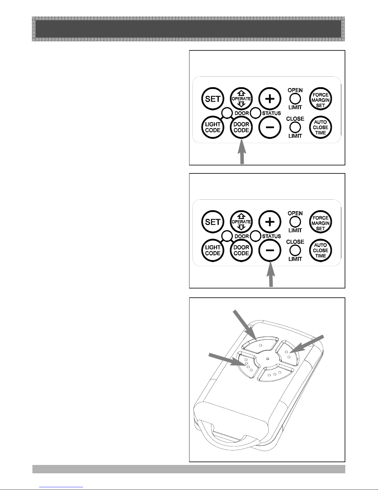
SETTING LIMITS
17
STEP 16
SETTING TRAVEL LIMIT POSITIONS
METHOD TWO: VIA THE TRANSMITTER
IMPORTANT NOTE: The OPERATE button will not
function until the open and close limits positions are set.
Remove the controls cover to access the controls panel
as shown in fig 26 page 16
16.1 CODING TRANSMITTER FOR SETTING LIMITS
1. Press and hold the Door Code button (Fig. 29).
2. Press button 1 on the transmitter for two seconds.
Release and pause for two seconds. Press the same
button again on the transmitter for two seconds.
3. Release Door Code button.
16.3 SETTING LIMITS
NOTE: The door and shuttle must be engaged into the
chain index and the door should be open approximately
half way.
1. Press button 4 (Fig. 31), the door will start closing,
release the button once you are 1 to 2 cm from your
desired closed limit position.
2. inch the door to your desired closed position by
. Pressing button 4
3. Once you are happy with the position press button 2,
this action will store into memory the closed limit
position.
4. Press button 1, the door will start opening. Release
the button once you are 1 to 2 cm from your desired
open limit position.inch the door to your desired
open position by. Pressing button 1
IMPORTANT WARNING: Please be aware that the
garage door will start closing automatically once step 5
is performed. The door will also automatically re-open
after fully closing with a small pause between the cycles.
5. Once you are happy with the position press button 2,
this action will store into memory the door limit
position. The door will now automatically close to its
limit position then fully open to calculate the safety
obstruction forces (ISS).
Please be aware of the above warning.
FIG. 30
FIG. 31
INCH OPEN
BUTTON 1
INCH CLOSE
BUTTON 4
SET
BUTTON 2
15.2 RESETTING DOOR LIMIT POSITIONS
The door travel limit positions can be deleted for new
positions by the following steps below:
1. Press and hold the (-) button (Fig. 30) for six (6)
seconds until you hear three beeps and the red
Close Limit LED starts to flash. Release the button.
2. Follow STEPS 15.1 to set new travel limit
positions.
FIG. 29
Page 18
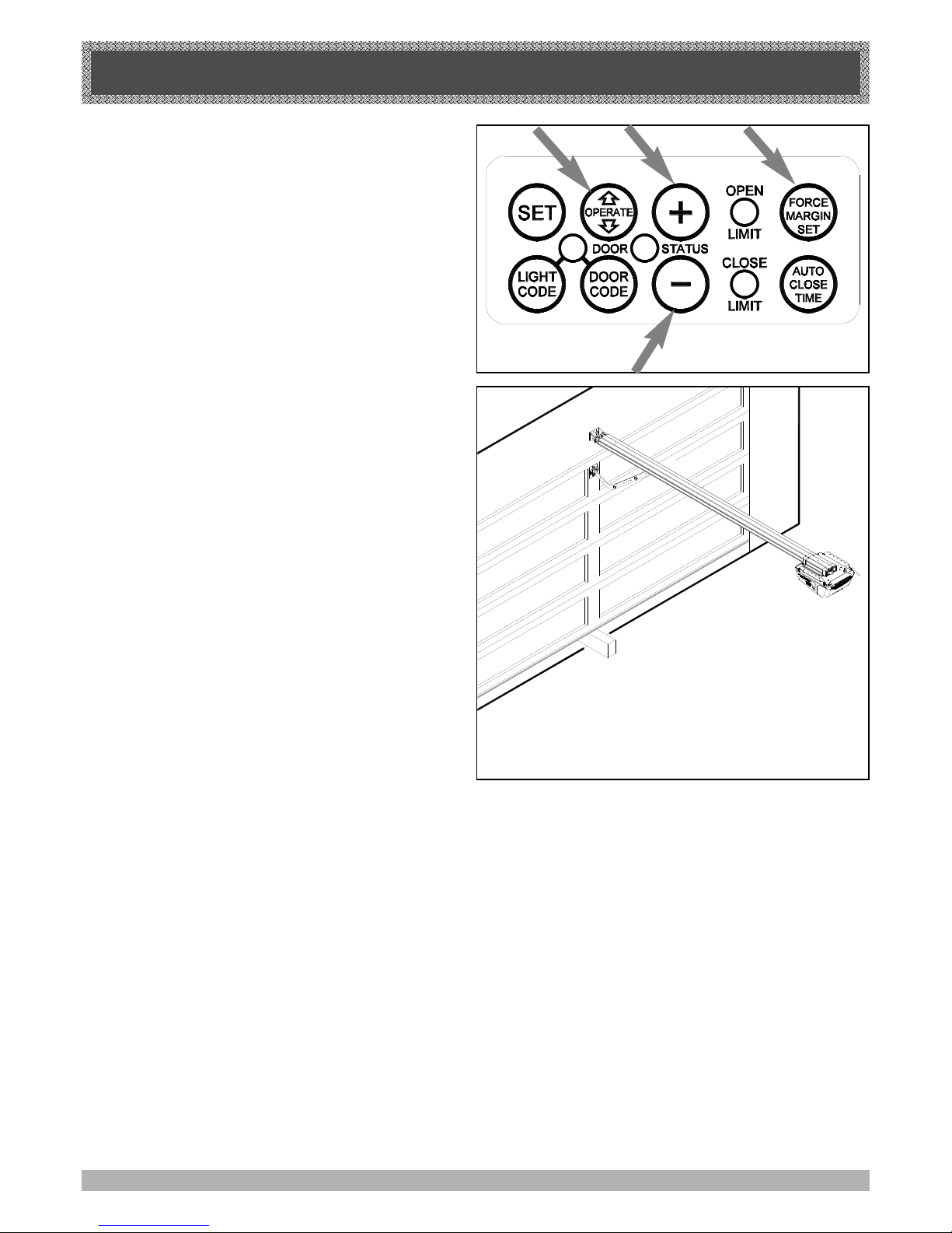
SETTING SAFETY OBSTRUCTION FORCE
18
STEP 17
SAFETY OBSTRUCTION TEST
Please take care when testing the Safety Obstruction
Force. Excessive force may cause SERIOUS PERSONAL INJURY and/or PROPERTY DAMAGE can result
from failure to follow this warning.
17.1 TESTING CLOSE CYCLE
1. Open the door by pressing the Yellow Operate button
(Fig. 32).
2. Place a length of timber approximately 50mm high on
the floor directly under the door (Fig. 33).
3. Press the Operate button to close door. The door
should strike the object and start to re-open.
17.2 TESTING OPEN CYCLE
1. Close the door by pressing the Operate button.
2. Press again to open the door. When the door
reaches half the opening distance, grab the bottom
rail of the door firmly, the door should stop.
If the door does not reverse readily when closing, or
stop when opening, the force may be excessive and
need adjusting, refer to STEP 17.4.
IMPORTANT WARNING: If the door is closing and is
unable to re-open when obstructed, discontinue use. Do
not use a door with faulty obstruction sensing. Repair
fault and re-test before using.
ADJUSTING SAFETY OBSTRUCTION FORCE
The Safety Obstruction Force is calculated automatically
and set in memory on the gdo-9 opener. It is
usually not necessary to adjust the Safety Obstruction
Force. The only time the force may need to be
increased is due to environmental conditions, for
example, windy or dusty areas, and areas with
extreme temperature changes.
17.3 TO INCREASE FORCE PRESSURE
1. Press and hold the Force Margin Set button (Fig. 32)
2. While holding down the Force Margin button, press
the Plus (+) button. Each press increases the force
margin. The Open Limit LED will flash each time the
Plus button is pressed to indicate an increase in
force. Test the force again as per step 17.1 and 17.2
above. If the Open Limit LED flashes continuously
when the Plus button is being pressed, this indicates
that the maximum force pressure setting has been
reached.
FIG. 33
FIG. 32
17.4 TO DECREASE FORCE PRESSURE
1. Press and hold the Force Margin Set button (Fig. 32).
2. While holding down the Force Margin button, press the
Minus (-) button. Each press decreases the force
margin. The Close Limit LED will flash each time the
Minus button is pressed. Test the force again as per
step 17.1 and 17.2 above. If the Close Limit LED flashes
continuously when the Minus button is being pressed,
this indicates that the maximum force pressure setting
has been reached.
17.5 TO RECALL FACTORY SET FORCE
1. While holding down the Force Margin Set button, press
the SET button (Fig. 32) for two seconds.
2. Release both buttons. The default setting should now
be recalled.
Page 19
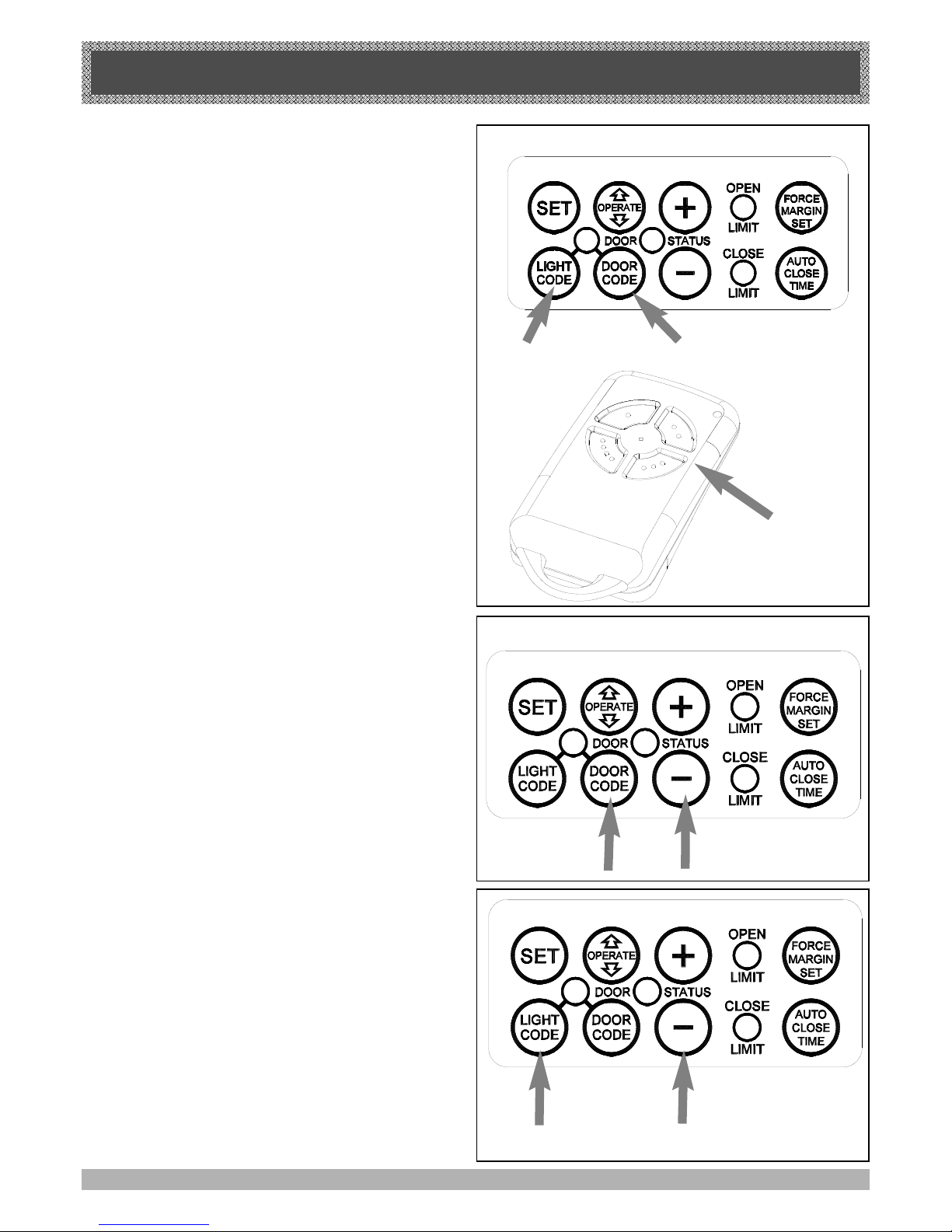
CODING TRANSMITTERS
19
STEP 18
SETTING TRANSMITTERS CODES
Make sure to connect the battery to the transmitters.
The memory in the openers receiver can store up to 24
different remote control transmitters.
18.1 STORING THE TRANSMITTERS CODE
1. Press and hold the Door Code button (Fig. 34).
2. Press the button (one of four) on the transmitter you
would like to use to control the door for two seconds,
pause for two seconds. Press the same button again
on the transmitter for two seconds.
3. Release the Door Code button.
4. Press the transmitter button to test if it operates
the door.
18.2. SETTING THE TRANSMITTER
TO OPERATE THE COURTESY LIGHT
The transmitter can be programmed to operate the courtesy light on the door opener.
1. Press and hold Light Code button (Fig. 34).
2. Press the button on the transmitter you would like to
use to switch on the light for two seconds, pause for
two seconds. Press the same button again on the
transmitter for two seconds.
3.
Release all buttons to store the transmitter in memory.
4. Press the transmitter button to test if it switches on
the light.
18.3. SETTING THE TRANSMITTER TO OPERATE
PET (PEDESTRIAN) MODE
1. Press and hold Door Code button and the ( - )
button (Fig. 35).
2. Press the button on the transmitter you would like to
use to control pedestrian mode for two seconds,
pause for two seconds. Press the same button again
on the transmitter for two seconds.
3.
Release all buttons to store the transmitter in memory.
4. Press the transmitter button to test if it operates the
pedestrian mode.
To change the default pet (pedestrian) door opening
position, refer step 24 on page 23.
18.4. SETTING THE TRANSMITTER TO OPERATE
VACATION MODE
1. Press and hold Light Code button and the Close
button (Fig. 36).
2. Press the button on the transmitter you would like to
use to control vacation mode for two seconds, pause
for two seconds. Press the same button again on
the transmitter for two seconds.
3.
Release all buttons to store the transmitter in memory.
4. To test, press and hold the transmitter button set for
vacation mode for five seconds to set Vacation Mode.
To reset Vacation Mode press the same button for two
seconds. Please note that when vacation mode is
activated all stored transmitters will be locked out. This
mode can only be deactivated by a transmitter which
has been stored to activate this mode.
FIG. 34
Press and hold
Door Code Button
Select one of the four
buttons you wish to use
to control the door.
FIG. 35
Press and hold
Door Code Button
FIG. 36
Page 20
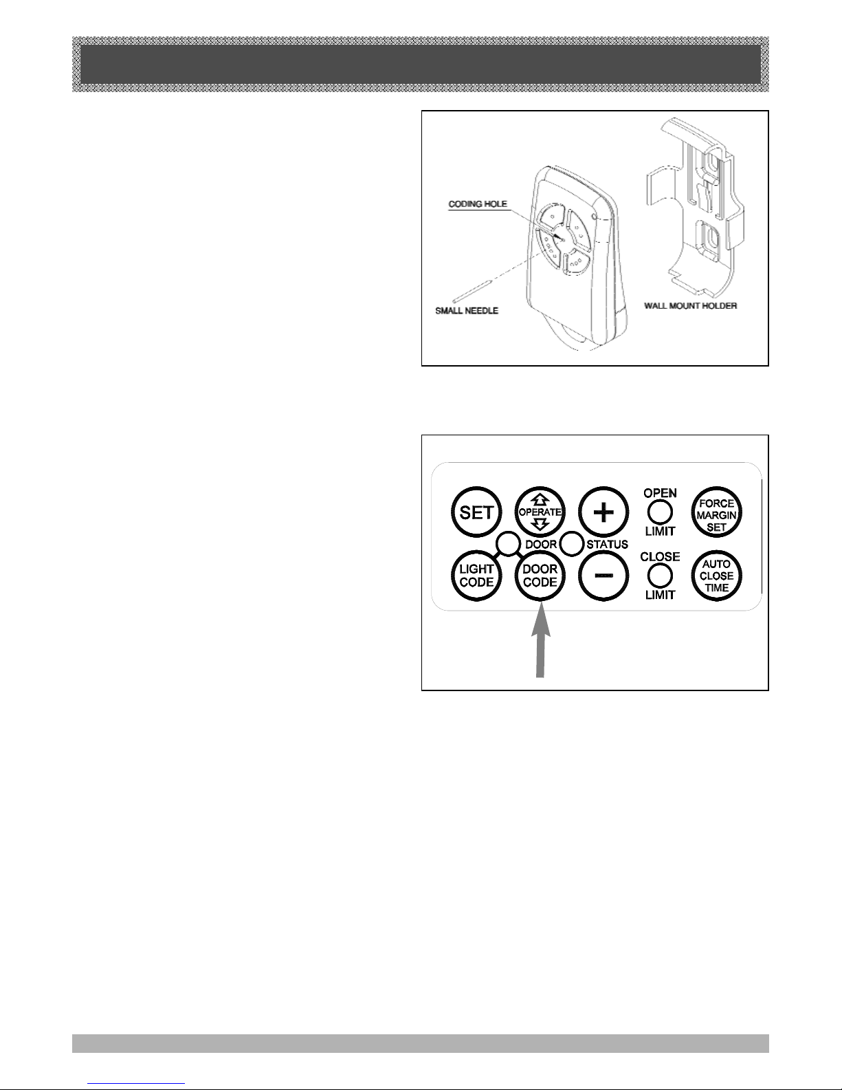
CODING TRANSMITTERS
20
STEP 19
STORING TRANSMITTER(S) FROM A REMOTE
LOCATION
Using this method you don’t need to have access to the
control panel on the Door Opener. However, you do
need a transmitter that is pre coded to the controller’s
receiver.
IMPORTANT NOTE: The Door or Courtesy Light must
be activated when the step below is performed. The
moving Door or Light switching on is to confirm from a
remote location that, the correct button was pressed,
and the transmitter is in range of the Opener.
1. Take any pre-coded transmitter. Press the button for
the function you require until the door is activated
and release.
2. Then using a small needle press and hold firmly for
two seconds through the Coding Hole (Fig. 37)
3. Within 10 seconds take the additional transmitter you
wish to code.
4. Press the button (one of four) on that transmitter you
would like to use to control the door for two seconds,
pause for two seconds. Press the same button again
on the transmitter for two seconds, the button should
now be recorded.
5. Wait for 10 seconds and then press the recorded
transmitter button to see if it operates the door.
STEP 20.
DELETING PROGRAMMED CODES
20.1 DELETING A STORED TRANSMITTER CODE
1. Select the transmitter you want to delete.
2. Press and hold the Door Code button (Fig. 38).
3. Press the transmitter button you would like to delete
for two seconds. Pause for two seconds. Press the
transmitter button again for two seconds.
4. Release the Door Code button. The code should now
be deleted. Confirm this by pressing the transmitter
button, the door should not respond.
20.2 DELETING ALL STORED TRANSMITTER
CODES
1. Turn the Power Off to the Opener.
2. Press and hold the Door Code button (Fig. 38).
3. Turn the Power On again, while holding the Door
Code button. The Open Limit, Close Limit and Door
Status LED’s will illuminate for about five seconds.
These LED’s will turn Off and the Coding LED will
illuminate. Release the Door Code button. All the
stored codes including the Courtesy Light codes
should now be deleted. Confirm this by trying to
operate the door by pressing the transmitters
previously used to control the door, the door should
not respond.
FIG. 37
FIG. 38
Page 21
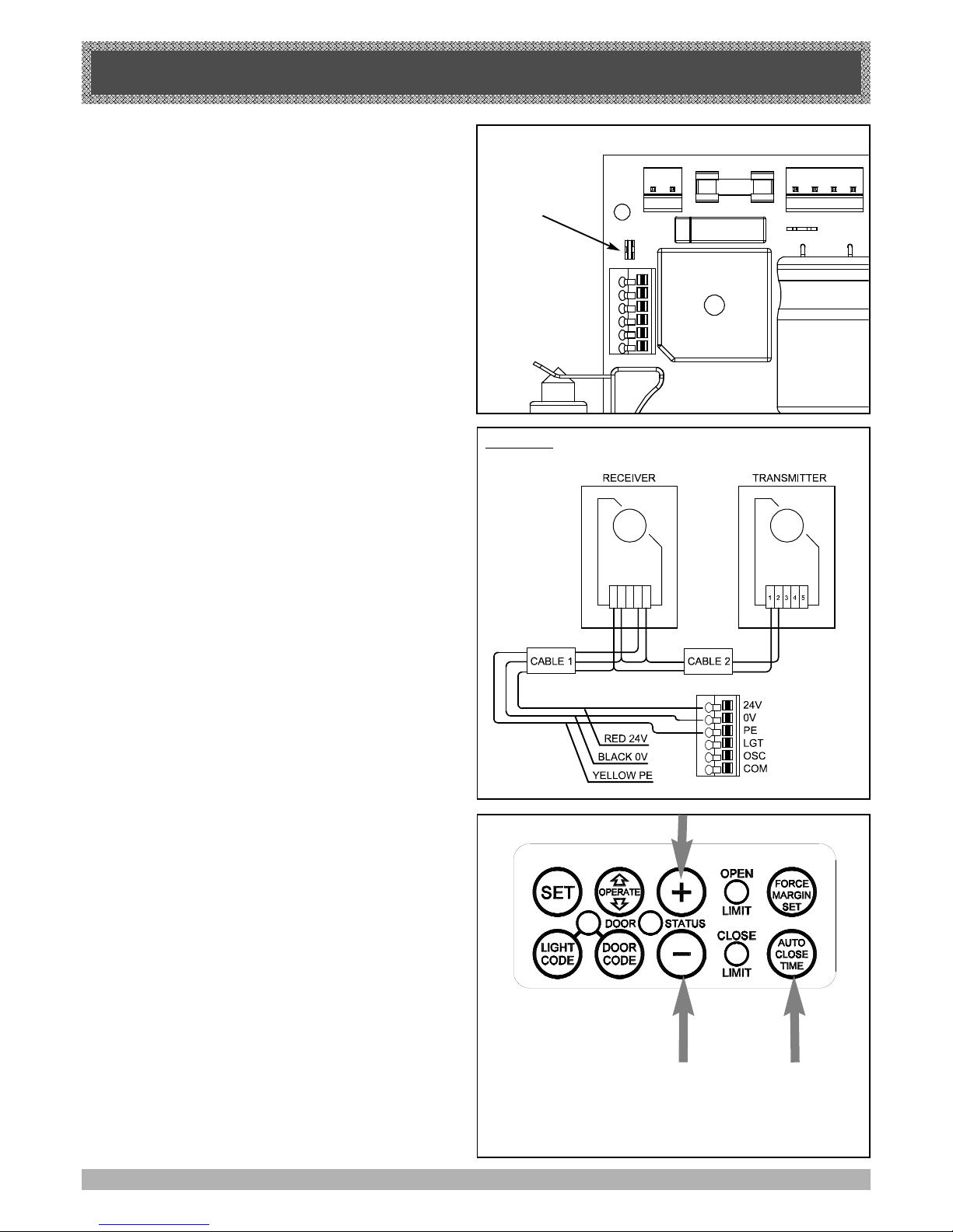
PE BEAM AND AUTO CLOSE
21
STEP 21.
FITTING THE SAFETY PHOTO
ELECTRIC BEAM SENSOR (OPTIONAL)
Locate the Photo Electric Beam (P.E.) normally closed
contact type in a strategic location within doorway. We
recommend 150mm above the floor level and as close
as possible to the door opening, inside the garage.
Remove shunt from P.E connector (Fig. 39) and connect
the wires from the P.E. wiring harness to terminal block
(Fig. 40). The wiring diagram is for Model PHBE (Order
Code 90214).
Make sure to align the beams correctly. Follow the
manual supplied with the Photo Electric Beam.
WARNING: When using Auto Close Mode and P.E.
beams, the doorway must be clear of all obstructions
and persons at all times. The location of the beam and
manner in which it is installed might not give safety protection at all times. Check to make sure that the height
of the beam and type used give maximum protection
possible.
STEP 22.
SETTING OF AUTO CLOSE TIME
IMPORTANT NOTICE: IT IS COMPULSORY TO
INSTALL A PHOTO ELECTRIC BEAM BEFORE
USING THE AUTO CLOSE MODE.
The Auto Close timer will only start after the Photo
Electric Beams (P.E.) path is broken and the auto close
time has been set. If the P.E. path is not broken the door
will remain open till the path is broken. If the Door
Opener incurs an obstruction (not from the P.E.) while
closing the door will re-open and not auto close until the
part of the P.E. beam is broken again.
SETTING AUTO CLOSE TIME
1. Press and hold the Auto Close Time button (Fig. 41).
2. While holding in the Auto Close Time button, press
the Plus (+) button. Each press of this button will
add one second to the auto close delay time.
3. To decrease the delay time follow Step 1 and press
the Minus (-) button. Each press will deduct one
second from the auto close time.
4. Press the Operate button or transmitter to open the
door. When the door is fully opened the Open Limit
green LED will flash to indicate that the auto close
mode is in operation. Break the path of the P.E.
Beam momentarily, this will initialize the auto close
mode. When the door reaches the fully opened
position, the door will pause for the set auto close
time and start to auto close.
FIG. 39
FIG. 40
Model: PE-2
FIG. 41
REMOVE
PE SHUNT
1 2 3 4 5
Page 22
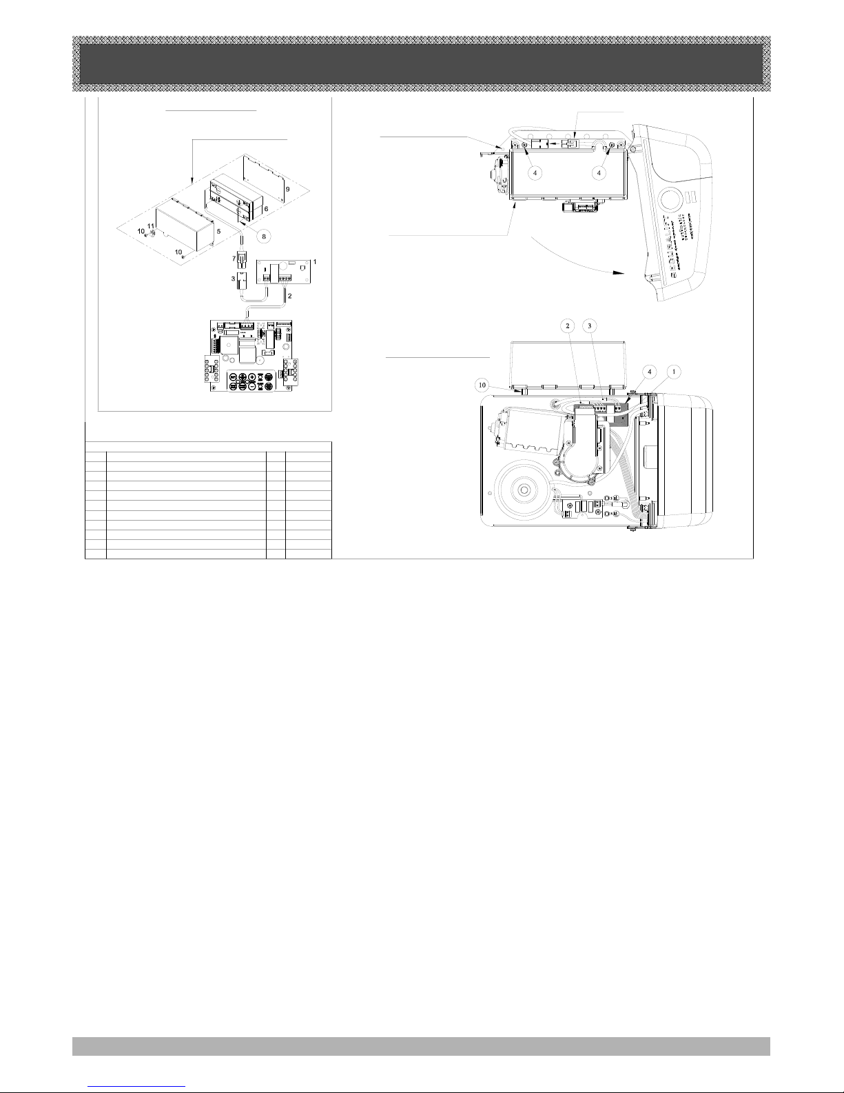
BATTERY BACKUP INSTALLATION
ORDER CODEQTYDESCRIPTIONITEM
1BATTERIES SUPPORT9
HEXAGON STANDOFF M410 2
BATTERY HARNESS
BATTERIES COVER
BATTERY COUPLING WIRE - ESV24
SBY-3 VERSION 1.00
SBY-3 ESV24 CHARGER HARNESS
SBY-2 BATTERY HARNESS
BATTERIES 12V SEC12-2.2 AGM TYPE
PAN HEAD SCREW W'WASHER M4x8
8
7
5
6
2
3
4
1
1
1
2
1
1
7
1
1
16480
11190
12005
15670
15470
16460
14115
10320
15660
00852
PARTS LIST
2. CONNECT WIRES AS SHOWN
4. CONNECT
1. REMOVE SCREWS &
SWING COVER TO OPEN
3. MOUNT BATTERY AND SECURE
WITH ITEM 4 & 10
5. CLOSE COVER AND
RE-SECURE WITH SCREW
REFER TO WIRING DIAGRAM
WIRING DIAGRAM
BATTERY ASSEMBLY (#01660)
22
BATTERY BACK UP (OPTIONAL)
The opener has provision to include a battery back up
module. This is an ideal addition if the garage door is the
only entrance to the garage or if the area is prone to
power cuts.
INSTALLATION
1. Disconnect power to the opener .
2. Remove screws and swing the cover to open fig 42.
3. mount battery pack and secure with item 4 and 10.
4. Mount the Charger Board SBY-3 on three hex spacers
pre mounted on base and
secure with three (3) M4 x 8 screws.
5. Feed 2-Wire battery Harness , through the grummet on
the base plate and connect to sby-3
6. Feed charger harness from sby-3 to control board and
plug 4 pin connector marked sby-3 on the control board
Warning: After Step 7 the opener may become active
(even when power is off). This is a result of a residual
charge in the batteries.
This will only occur if batteries still hold some charge.
7. Connect battery harnesses item 3 and 7 together
(Fig. 42).
8. Reconnect power
FIG. 42
TESTING BATTERY BACK UP
1. Press either operate button or transmitter
to test the opener.
2. Whilst door is in motion disconnect mains power
The door should continue to operate as normal.
Note: Wait for the door to complete its travel.
3. Press operate or transmitter to activate the door.
4. Whilst door is in motion re-connect power. The door
should complete the cycle as normal.
TROUBLE SHOOTING
If door stops or moves very slowly under battery power:
- Batteries may be weak or have no charge
- connect power and allow to charge.
- Batteries may take 24 - 48 hours to reach maximum
charge capacity.
Page 23
FINAL SET UP
23
23. SETTING OF COURTESY LIGHT TIME
The preset courtesy light time on the door opener is
3 minutes. This time can be changed by the following:
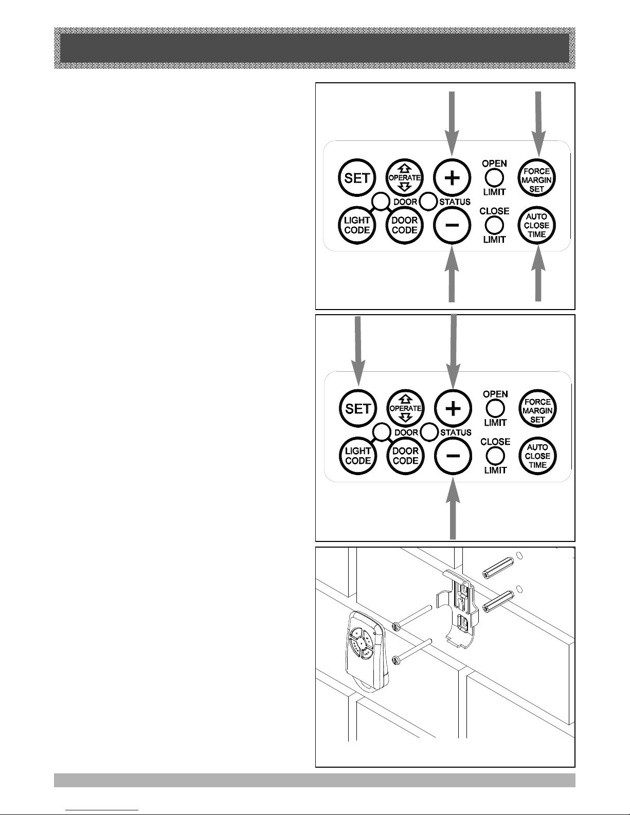
1. Press in and hold both the Auto Close Time button
and Force Margin Set button (Fig. 43).
2. While holding in the two buttons, press the Plus (+)
button. Each press of the button will add 10 seconds
to the light time.
3. To decrease the time follow Step 1 and press the
Minus (-) button. Each press will deduct 10 seconds
from the light time.
4. To recall the factory set default light time press in and
hold together the Auto Close Time button, the Force
Margin Set button and the Set button for about
2 seconds. Release all buttons, the factory set
default of 3 minutes will be recalled.
24. SETTING THE PET MODE DOOR OPENING
POSITION.
The default PET (Pedestrian) position is factory preset
to a predetermined height. The PET mode status is
indicated by both the Open and Close Limit LED’s being
illuminated. The default position can be changed by the
following:
1. Make sure the door is in the closed position. Press
and hold the Plus (+) button for six (6) seconds
(Fig. 44), you should hear three beeps and the Open
and Close LEDs will flash rapidly.
2. Press the Plus (+) or Minus (-) button (Fig. 44) to
move the door to your required new pet open door
position.
3. Press the Set button (Fig. 44) to record the new
position.
The Pet mode is activated from a transmitter button
coded to that function. When activated the door drives to
the preset position from either above or below. If the Pet
button is pressed while the door is moving the door will
be stopped. If the Pet button is pressed when the door
is in the Pet position, then the door will be closed. No
auto close is enabled.
25. INSTALLATION OF WALL MOUNTED
TRANSMITTER HOLDER
1. Mount the holder in a location out of reach of children
and convenient to the customer. (Fig 45). Make sure
the door is visible from this location.
2. The transmitter can be easily clipped in and removed
from the holder as required.
3. To set the transmitter codes refer to Step 18 on
Page 19.
26. RE-INITIALIZING THE OPENER
To re-initialize the opener press and hold the Set Button
for two (2) seconds, the beeper will sound once. The
door will start to move and re-calculate force margins.
The door can move between the open and close limit
positions up to four (4) times (depending on the position
of the door and the power up condition). A single beep
will be heard once the initialization is complete. The
door is now ready for use.
FIG. 43
FIG. 45
FIG. 44
FIG. 45
Page 24
PARAMETERS
24
DOOR STATUS INDICATORS
BUTTON FUNCTION
Operate Opens/Stops/Closes the door
Door Code Codes a transmitter button for Operate function
Light Code Codes a transmitter button for light function
Door Code & Minus (-) Codes a transmitter button for pet (pedestrian) function
Light Code & Minus (-) Codes a transmitter button for vacation function
Force Margin Set & Pus (+) Increases the obstruction force margin setting
Force Margin Set & Minus (-) Decreases the obstruction force margin setting
Force Margin Set (then) Set Reloads the factory set default obstruction force margin setting
Auto Close Time (then) Plus (+) Increases the auto close delay time
Auto Close Time (then) Minus (-) Decreases the auto close delay time
Auto Close Time (then) Set Reloads the factory set default auto close delay time
Force Margin Set & Auto Close Time (then) Plus (+) Each press of the open button increases the light time by 10 secs.
Force Margin Set & Auto Close Time (then) Minus (-) Each press of the open button decreases the light time by 10 secs.
Force Margin Set & Auto Close Time (then) Set Reloads the factory set default light time
Minus (-) (for 6 secs.) Clears the door limits set positions. Limits then need to be reset.
Set & Close (for 2 secs.) Enters pet (pedestrian) position mode.
Set (the power on) and hold until all LEDs are off Deletes control parameters excluding transmitter storage memory.
Door Code (the power on) and hold until all LEDs are off Deletes all transmitter storage memory.
Set & Door Code (the power on) and hold until all LEDs are off Deletes all control parameters and transmitter storage memory.
Set Re initialises opener obstruction force margin.
DOOR OPENER STATE OPEN LED GREEN
CLOSE LED
RED
DOOR STATUS
LED YELLOW
BEEPER
OPEN ON
CLOSE ON
OPENING FLASHING
CLOSING FLASHING
DOOR TRAVEL STOPPED FLASHING FLASHING
DOOR OBSTRUCTED WHEN OPENING FLASHING
DOOR OBSTRUCTED WHEN CLOSING FLASHING
BEEPS WHILE
DOOR IS MOVING
OPENER OVERLOADED
ALTERNATING
FLASHES
ALTERNATING
FLASHES
DOOR IN OPEN POSITION WITH
AUTO CLOSE MODE SELECTED
ONE SECOND
FLASHES
MAINS POWER INTERRUPTED
RAPID
FLASHES
Page 25
POWER SUPPLY 230V - 240V AC 50Hz
TRANSFORMER RATING........................................................24V DC
STANDBY POWER ....................................................................2.2 Watts
MOTOR POWER........................................................................100 Watts
MOTOR TYPE.............................................................................24V DC Permanent Magnet
SHUTTLE TRAVEL DISTANCE IN THE C RAIL...........................2.8 M APROX ( STANDARD)
MAXIMUM SHUTTLE TRAVEL DISTANCE IN THE C RAIL.....5 M( WITH EXTENDED C RAIL)
MAXIMUM DOOR OPENING: WIDTH.............................5500mm (16.5 SQ M )
HEIGHT..........................3000mm
WEIGHT...........................100 Kg
SHORT TERM PEAK FORCE....................................................800 N (80Kg)
LIFT FORCE................................................................................500 N (50Kg)
NOMINAL FORCE.......................................................................150 N ( 15 KG )
RECEIVER TYPE.........................................................................UHF 433.92 MHz. AM Receiver
RECEIVER CODE STORAGE CAPACITY.............................24 x 4 Button Transmitter Codes
TRANSMITTER FREQUENCY.................................................433.92 MHz
CODING TYPE..............................................................................Code Hopping
NUMBER OF CODE COMBINATIONS....................................Over 4.29 Billion Random Codes
CODE GENERATION..................................................................Non-linear Encryption Algorithm
PTX-4 TRANSMITTER BATTERY............................................A23 Alkaline 12 Volts
EAT-1 TRANSMITTER BATTERY:...........................................CR1220 Lithium 3 Volts
COURTESY LIGHT......................................................................LED ( Light emitting diodes )
CONTROLLER FUSE..................................................................10A Slow Blow
DEFAULT SETTINGS AND SPECIFICATIONS
25
Note:
Intermittent operations may occur in areas which experience very strong winds. The strong wind puts extra pressure on the door
and tracks which may in turn trigger the safety obstruction detection system intermittently.
DEFAULT STEP MAXIMUM
MAXIMUM MOTOR RUN TIME 25 Secs. — —
COURTESY LIGHT TIME 3 Mins. 10 Secs. 4 Mins.
OBSTRUCTION FORCE MARGIN 8 1 20
AUTO CLOSE TIME 0 Secs. 1 Sec. 4 Mins.
FACTORY DEFAULT SETTINGS
TECHNICAL SPECIFICATIONS
Page 26
TROUBLE SHOOTING
26
*Please Note: Some areas may be prone to excessive radio interference brought on by devices such as cordless telephones, wireless
stereo headphones and baby monitors. It is possible that these devices could cause a degree of interference such as to greatly reduce
the range of the transmitter. In such an instance please contact your ATA dealer for an alternative frequency replacement kit. As this is
not a warrantable situation but an environmental issue charges may apply for the changeover.
SYMPTOM POSSIBLE CAUSE REMEDY
Door will not operate.
Mains power not switched on.
Door is obstructed.
Door is locked or motor jammed.
Door tracks/hardware damaged.
Switch on mains power.
Remove obstruction.
Unlock door or remove jam.
Door requires service/repair by qualified
technician.
Door starts to close but automatically
reverses to open position.
Adverse weather conditions (wind or cold)
causing door to stiffen and become tight in
the tracks.
Possible obstruction in the doorway.
Increase force margin setting See Step 17.3
on page 18.
Remove obstruction.
Door operates from drive unit (oprate)
button but not from transmitter.*
See note.
Transmitter code not stored in memory.
Flat Battery.
Code transmitter in to openers memory.
Refer Step 18 on page 19.
Replace battery - A23 Alkaline 12V.
Door will not close fully.
Door limits position need to be reset.
Reset limits position. See Page 12.
Door will not open fully. Door limits position need to be reset. Reset limits position. See Page 12.
Courtesy light not working. faulty LED module Replace LED module
Auto close not working.
PE Beam or wiring faulty
PE Beam not aligned correctly.
PE Beam is obstructed.
Door obstructed when closing.
Auto close time not set.
Repair PE Beam or replace wiring.
Re-align optics. See PE Instructions.
Remove obstruction from the path of PE.
Remove obstruction.
See Step 22 on page 21.
DATE MAINTENANCE PERFORMED BY SIGNATURE AMOUNT INV. No.
Please Note: Failure to maintain your garage door may void the warranty for your garage door opener.
Page 27
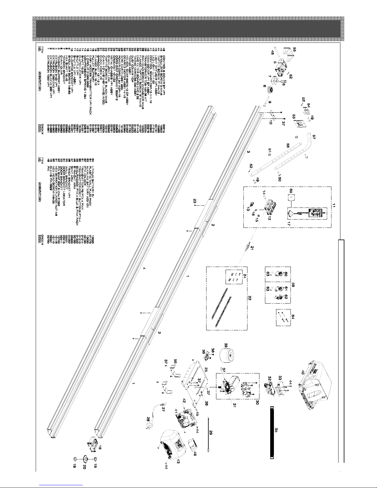
SPARE PARTS LIST
MANUAL RELEASE
WHEN ORDERING SPARE PARTS PLEASE QUOTE THE ORDER CODE NUMBER TO YOUR INSTALLER/DEALER.
page 27
Page 28

WARRANTY AND EXCLUSION OF LIABILITY
28
1. This warranty is an addition to any non-excludable conditions or warranties that are implied into this contract by
relevant statute, including the Trade Practices Act 1974 (Cth).
2. Subject to all of the matters set out below, Automatic Technology Australia Pty Ltd (“ATA”) warrants:
(a) swing and sliding gate opener drive units for twelve (12) months or 2500 cycles, whichever occurs first;
(b) roll-up and overhead door opener drive units for twenty four (24) months or 5000 cycles, whichever occurs first;
and
(c) all components and accessories for twelve (12) months,
from the date of purchase (specified in the sales docket receipt) as free of any defects in material and workmaship.
3. This warranty applies only where the purchaser:
(a) immediately notifies ATA or the retailer of the alleged defect;
(b) returns the product to the retailer; and
(c) presents the relevant sales docket and this warranty document to the retailer to confirm the date of purchase.
4. Except for this warranty, ATA gives no warranties of any kind whatsoever (whether express or implied), in relation to
the product, and all warranties of whatsoever kind relating to the product are, to the extent permissible by statute,
hereby excluded.
5. To the extent permissible by statute, ATA disclaims any liability of whatsoever nature in respect of any claim or
demand
for loss or damage which arises out of:
a) accidental damage to or normal wear and tear to the product or to the product’s components;
b) any cost relating to damage resulting from wear and tear;
c) blown fuses, loss or damage caused by electrical surges, power surges or power spikes;
d) loss or damage due to theft, fire, flood, rain, water, lightning, storms or any other acts of God;
e) maximum continuous operating time exceeding one (1) minute in ten (10);
f) maximum operating force exceeding *20Kg (200N) when moving the door or gate manually to the open or
closed position;
g) door surface area and/or weight exceeding 16.5m2 and 100Kg respectively;
h) residential gate weight exceeding 400Kg;
i) door or gate not in safe and correct working order and condition;
j) evidence of unauthorised repairs;
k) any cost relating to damage caused by misuse, negligence or failure to maintain the equipment in a proper
working
order as per clauses (d) through (i);
l)
installation, adjustment or use which is not in accordance with the instructions set out in installation
instruction manual
m) attempted or complete modification or repairs to the product carried out by a person who is not authorised or
has not been trained by ATA to carry out such modification or repairs;
n) faulty or unsuitable wiring of structure to which the product is fixed or connected;
o) radio (including citizen band transmission) or any electrical interference;
p) damage caused by insects;
q) loss or damage to any property whatsoever or any loss or expense whatsoever resulting or arising there from
or
any consequential loss;
r) any cost or expense arising due to manufacturer recall of any product;
s) any cost or expense due to negligence of the approved service provider;
t) installation of a residential garage door or gate opener in a commercial or industrial situation or a non-single
residential dwelling.
6. ATA’s liability under this warranty is limited, at ATA’s absolute option, to replacing or repairing the product which ATA,
in its unfettered opinion, considers to be defective either in material and/or workmanship or to credit the dealer with
the
price at which the product was purchased by the dealer.
7. This warranty does not extend to cover labour for installation.
8. This warranty is limited to Return-to-Base (RTB) repair and does not cover labour for on-site attendance.
9. This warranty is void if the Product is not returned to the manufacturer in original or suitably secure packaging.
10. This warranty is only applicable for repairs to the product carried out within Australia.
11. This warranty does not cover consumable items including globes, batteries and fuses.
12. This warranty is not transferable.
13. Where the Product is retailed by any person other than ATA, except for the warranty set out above, such person has
no authority from ATA to give any warranty or guarantee on ATA’s behalf in addition to the warranty set out above.
Notes:
1. One (1) cycle = one (1) open and one (1) close action of the door or gate.
2. This warranty is to be read in conjunction with the owner’s copy of the installation instruction manual.
3 *The door should be balanced in such a way that the user manually is able to open or close the door without using
force not greater than 150N (15 kg ) although a greater force may be required for the start of the movement.
 Loading...