

Page 1

Water Resistant Roll Up Door Opener
DOMINATOR
Instruction Manual
(Instruction d’Installation)
TM
ShedMaster
®
Conforms to UL 325
Certified to CSA
C22.2 No.247
Doc # 160089_01
Part # 86368
Released 15/11/18
Page 2

WARNING!: It is vital for the safety of persons to follow all
instructions. Failure to comply with the installation instructions
and the safety warnings may result in serious personal injury
and/or property and remote control opener damage. Please
save these instructions for future reference.
ELECTROCUTION!: To reduce the risk of electric shock, this
equipment has a grounding type plug that has a third (grounding)
pin. This plug will only fit into a grounding type outlet. If the
plug does not fit into the outlet, contact a qualified electrician
to install the proper outlet. Do not change the plug in any way.
This operator is not equipped for permanent wiring. Contact a
qualified electrician to install a suitable receptacle if one is not
available.
AVERTISSEMENT! pour la sécurité des usagers, il est
essentiel de suivre toutes les instructions. Le non- respect des
instructions d’installation et des avertissements de sécurité
peut causer de graves blessures et/ou endommager l’appareil
et la télécommande. Conservez ces instructions en lieu sûr.
AVERTISSEMENT! Pour réduire les risques d'électrocution,
cet appareil est équipé d’une fiche avec broche de mise à la
terre. Cette fiche ne peut être branchée que dans une prise
avec mise à la terre. S’il n’est pas possible de la brancher dans
la prise, faites poser une prise appropriée par un électricien
qualifié. Ne pas modifier la fiche.
Ce matériel est pas équipé pour le câblage permanent. En
l'absence de réceptacle approprié, contactez un électricien
qualifié pour en installer un.
2
GDO-8V3 Shed Master Instruction Manual
Page 3

Table of Contents
Installation Instructions
© Copyright 2017
1. Safety Information 4
2. Specifications 6
3. Kit Contents 7
4. Setup Requirements 8
4.1 The Opener: 8
4.2 Unsuitable Door Types 8
4.3 Sideroom 8
4.4 Check Operation of Door 8
5. Opener Safety & Security 9
5.1 Your Door CAN NOT be used when: 9
5.2 Your Door CAN be used when: 9
5.3 To Disengage the Opener: 9
5.4 To Re-Engage the Opener: 9
6. Before Installation 10
6.2 Fit the Weight Bar 11
6.2.1 If the door has a handle: 11
6.2.2 If the door does not have a handle: 11
6.3 Pinning the Door 12
6.4 Proping the Door 12
6.9 Safety Testing 17
6.9.1 Testing the Close Cycle 17
6.9.2 Testing the Open Cycle 17
6.9.3 To Increase Force Pressure 17
6.9.4 To Decrease Force Pressure 17
6.9.5 To Recall Factory Set Force 17
6.10 Attach Warning Labels 18
6.11 Accessories 18
6.12 Coding a Transmitter 20
6.12.1 Storing the Transmitter Code 20
6.12.2 Coding to Enable Vacation Mode 20
6.12.3 Remotely Coding Transmitters 20
6.12.4 Erasing a Stored Transmitter Code 20
6.12.5 Erasing All Transmitter Codes 20
Home Owner Instructions
6.5 Mounting the Opener 13
6.5.1 Raising the Door: 13
6.5.2 Mounting the Opener: 13
6.6 Safety Beam Installation 14
6.6.1 Mounting the beam 14
6.6.2 Wiring Connection 14
6.7 Setting the Datum 15
6.8 Setting the Travel Limits 16
6.8.1 Initial Preparation: 16
6.8.2 Set the Limit Positions: 16
6.8.3 Resetting the Door Limit Positions 16
6.8.4 Reset all Factory Defaults 16
7. Operation Instructions 21
7.1 How to Use Your Operator 22
7.1.1 To Operate the opener: 22
7.1.2 Replacing the Battery: . 22
7.2 User Operating Controls 23
7.3 Door Status Indicators 23
8. User Maintenance Instruction 24
8.1 Door Maintenance 24
8.2 If You Need a Service Call 24
9. Troubleshooting 25
10. Customer Agreement & Warranty 26
Shed Master Instruction Manual GDO-8V3
Diamond PD Power Drive : Instruction Manual
3
Page 4

1. Safety Information
WARNING!
• This operator should be installed in accordance with relevant US and
Canada Standards.
• Place the attached Entrapment Warning Label on wall next to wall
mounted transmitter, within sight of door.
• This operator is not suitable for commercial, industrial or common
entry applications.
• This operator is a plug in domestic appliance and is designed for
indoor use only. It must be installed in a dry position that is protected
from the weather.
• Door must have Safety Beams fitted.
• Activate the operator only when the garage door is in full view, free of
obstructions and with the operator properly adjusted.
• Watch the moving door and keep people away until the door is
completely opened or closed.
ELECTROCUTION:
• Installation and wiring must be in compliance with your local building
and electrical codes.
• This operator is not equipped for permanent wiring. Contact a
qualified electrician to install a suitable receptacle if one is not
available.
• To reduce the risk of electric shock, this equipment has a grounding
type plug that has a third (grounding) pin. This plug will only fit into
a grounding type outlet. If the plug does not fit into outlet, contact
a qualified electrician to install the proper outlet. Do not change the
plug in any way.
• If the power cord is damaged, it must be replaced by the manufacturer,
its service agent or a similarly qualified person in order to avoid a
hazard.
• Connect the power cord only to properly earthed mains. If an
extension lead must be used, make sure it is a 3-core lead and
approved to 7 amp capacity.
Please read these important safety rules
These safety alert symbols indicate a personal
safety or property damage instruction exists.
READ THESE INSTRUCTIONS CAREFULLY.
This automatic garage door operator is designed and tested
to offer safe service provided it is installed and operated
in strict accordance with the following safety rules. Failure
to comply with the installation instructions and the safety
warnings may result in death, serious personal injury and/or
property damage.
CAUTION:
• If your garage has no pedestrian entrance door, an emergency
access device should be installed. This accessory allows manual
operation of the garage door from outside in case of power failure.
• Keep the garage door balanced. Sticking or binding doors must be
repaired. Garage doors, door springs, brackets and their hardware
are under extreme tension and can cause serious personal injury.
Do not attempt any garage door adjustment. Do not use if repair
or adjustment is needed. Call for professional garage door service.
• Position the Garage Door Operator so that the power plug is
accessible when inserted into the power outlet.
• Install the wall transmitter in a location where the garage door is
visible, but out of the reach of children at a height of at least 5 feet
(1.53m).
• To avoid serious personal injury from entanglement, remove all
unnecessary ropes or chains and disable any equipment such as
locks which are not needed for powered operation.
• Do not wear rings, watches or loose clothing while installing or
servicing a garage door operator.
• Ensure ladder is the correct type for the job and is on flat ground.
We recommend the user has 3 points of contact while on ladder.
• Activate the operator only when the garage door is in full view,
free of obstructions and with the operator properly adjusted.
• This unit is not user serviceable. Unplug the power cord before
removing the cover. Ensure that the power cord is attached clear of
all moving parts. Ignoring these instructions can cause electric shock.
4
GDO-8V3 Shed Master Instruction Manual
• The operator is not intended for use by young children or infirm
persons without supervision.
• Keep transmitters away from children.
• Do not allow children to play with door controls.
Page 5

Sécurité
© Copyright 2017
AVERTISSEMENT!
• Cet appareil doit être installé conformément aux normes US et
canadiennes en vigueur.
• Placez l’étiquette avertissant du risque de se faire piéger sur le mur
à proximité de l’émetteur, en vue de la porte.
• Cet appareil n'est pas conçu pour des applications commerciales,
industrielles ou d'entrée commune.
• Cet appareil est un accessoire domestique conçu pour être utilisé
uniquement à l'intérieur. Il doit être installé au sec et à l'abri des
intempéries.
• La porte doit être équipée de faisceaux de sécurité.
• Activez l'appareil uniquement lorsque la porte du garage est à la vue,
exempte d'obstacles et avec l'appareil bien réglé.
• Suivez la porte pendant l'ouverture ou la fermeture, et veillez à
ce que personne ne se trouve à proximité tant qu'elle n'est pas
complètement ouverte ou fermée.
Lisez attentivement ces règles de
sécurité.
Ces pictogrammes indiquent une consigne
de sécurité pour les personnes ou les biens.
LISEZ CES INSTRUCTIONS ATTENTIVEMENT.
Cette commande automatique pour porte de garage est
conçue et testée pour fonctionner en toute sécurité. Pour
ce faire, elle doit être installée et utilisée dans le strict
respect des règles de sécurité suivantes. Le non-respect des
instructions d'installation et des avertissements présent un
risque de mort, de blessure grave et/ou de préjudice pour
les biens.
PRUDENCE:
• Si votre garage ne comporte pas de porte pour piétons, il convient
d'installer un dispositif d'accès d'urgence. Cet accessoire permet
d'actionner la porte de garage manuellement de l'extérieur en cas
de panne d'électricité.
ÉLECTROCUTION:
• L'installation et le câblage doivent être effectués conformément aux
codes de la construction et de l'électricité en vigueur.
• Cet appareil n'est pas équipé pour un câblage permanent. En
l'absence de réceptacle, contactez un électricien qualifié pour en
installer un.
• Pour réduire le risque d'électrocution, cet équipement est pourvu
d'une prise avec broche de mise à la terre. Celle-ci ne peut être
branchée que dans une prise compatible. Sinon, demandez à un
électricien qualifié d'installer une prise de courant adéquate. Ne la
remplacez pas vous-même.
• Si le cordon électrique est abîmé, il doit être remplacé par le fabricant,
son SAV agréé ou un technicien qualifié.
• Branchez le cordon électrique uniquement à une prise secteur
dûment reliée à la terre. Si vous devez utiliser une rallonge, assurezvous qu'elle est tripolaire et d'une capacité de 7ampères.
• Cet appareil n'est pas réparable par l'utilisateur. Avant de retirer
le capot, débranchez le cordon électrique. Assurez-vous qu'il ne
risque pas d'entrer en contact avec des pièces en mouvement. Le
non-respect de ces instructions peut avoir une électrocution pour
conséquence.
• Veillez à ce que la porte du garage soit bien équilibrée. Si une
porte reste «collée» ou qu'elle «accroche», elle doit être réparée.
Les portes de garage, les ressorts de porte, les pattes de fixation
et les éléments matériels sont soumis à une tension extrême et
peuvent blesser gravement. Ne tentez pas de régler la porte de
garage par vous-même. Ne l'utilisez pas si une réparation ou un
réglage est nécessaire. Faites appel à un technicien spécialisé.
• Positionnez le dispositif de commande de manière à ce que la
prise de courant soit accessible lorsqu'elle est branchée.
• Installez l'émetteur mural à un emplacement où la porte du garage
est visible, mais hors de portée des enfants, à une hauteur d'au
moins 1,50m.
• Rangez cordes et chaînes pour éviter de vous blesser, et désactivez
les serrures et autres équipements qui ne sont pas nécessaires
pour une utilisation sous tension.
• Pendant l'installation ou la réparation d'un dispositif de commande
de porte de garage, retirez bijoux et montre, et attachez vos
vêtements.
• Utilisez un escabeau adéquat et stable. Lorsque l'utilisateur se
tient sur un escabeau, il est conseillé de veiller à ce que les points
de contact soient au nombre de trois.
• Activez l'appareil uniquement lorsque la porte du garage est à la
vue, exempte d'obstacles et avec l'appareil bien réglé.
• L'appareil ne doit pas être utilisé sans supervision par de jeunes
enfants ou des personnes infirmes.
• Les émetteurs doivent rester hors de portée des enfants.
• N'autorisez pas les enfants à jouer avec les commandes de porte.
Shed Master Instruction Manual GDO-8V3
Diamond PD Power Drive : Instruction Manual
5
Page 6

2. Specifications
Technical Specifications DOMINATOR ShedMaster
GDO-8V3
Power supply 120Va.c. 60Hz
Maximum door opening
Width:
Height:
Maximum Door Weight:
Door Area:
Door must be well balanced and able to be operated by
hand, as per warranty conditions and standard
AS/NZS 4505:2012
Minimum sideroom 40mm
Lift Force 450N
Nominal force 120N (12kg)
Receiver type Multi-frequency UHF FM
(433.47, 433.92 & 434.37MHz)
Receiver code storage capacity 8 X Triocode
Coding System TrioCode
5500mm
2700mm
100kg
2
16.5m
TM
128
4-button Transmitters
TM
128 Type
®
Coding type Code Hopping
Number of code combinations Over 100 billion random codes
Transmitter battery CR2032 (3 Volts)
Courtesy light Light Module (Optional)
Network connectivity Not Available
Note: Intermittent operations may occur in areas which experience very strong winds. The strong wind puts extra pressure on the
door and tracks which may in turn intermittently trigger the safety obstruction detection system.
6
GDO-8V3 Shed Master Instruction Manual
Page 7

3. Kit Contents
© Copyright 2017
3
4
5
6
7
2
1
8
9
1
1. 1 x GDO-8V3 drive unit
2. 1 x Safety Beam Kit
3. 1 x PTX-5 Transmitters
4. 1 x Wall Transmitter
5. 1 x Weight Bar
Fastner Bag
6. 2 x Nilock Nut
7. 2 x 3/16 x 1/2 flat washers
8. 2 x Pan Head Screw M4 x 50
9. 2 x Locking Bar Covers
Fig. 3.1
Shed Master Instruction Manual GDO-8V3
Diamond PD Power Drive : Instruction Manual
7
Page 8
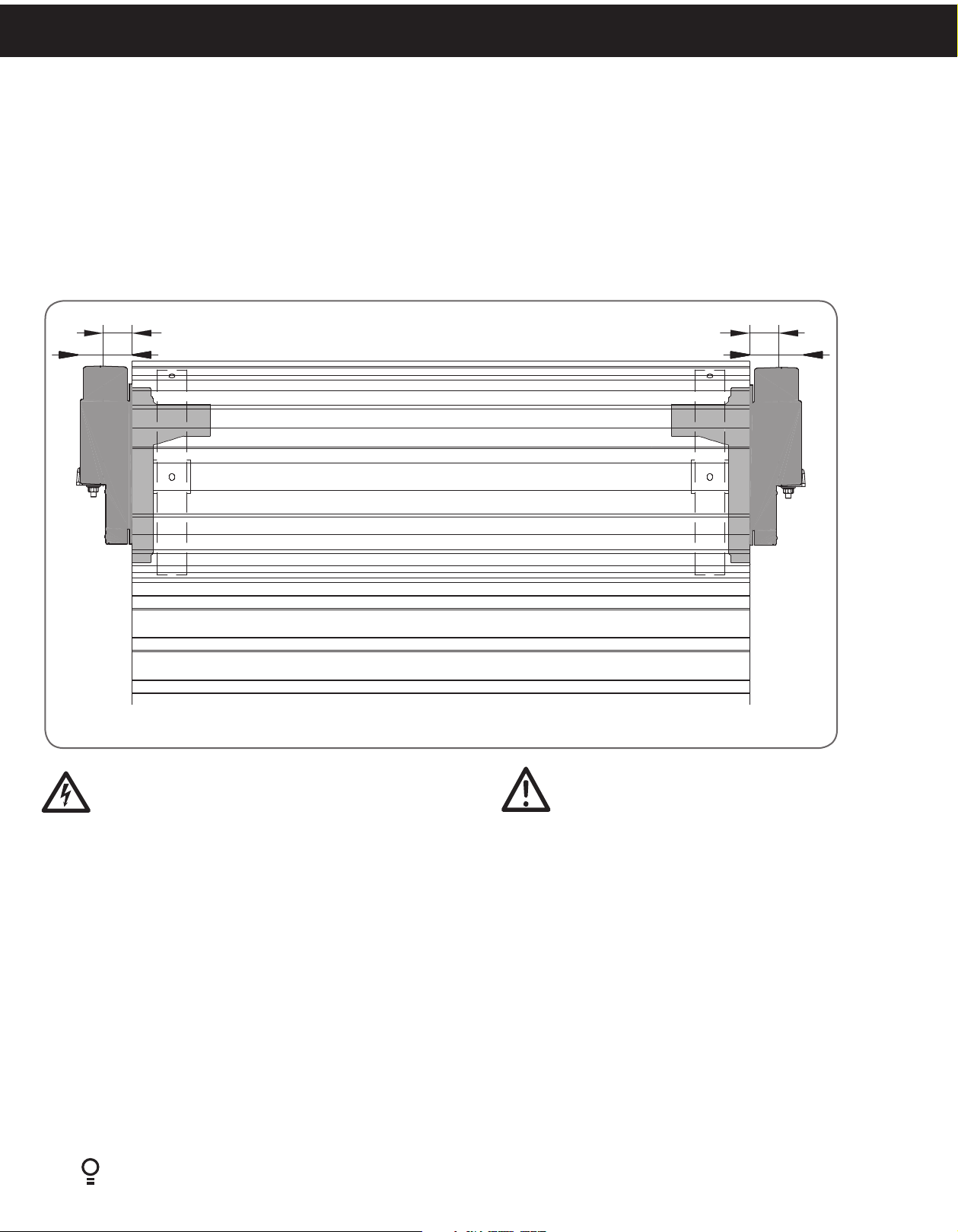
4. Setup Requirements
4.1 The Opener:
a. MUST BE installed in a dry position, protected from weather. (Moisture or corrosion not covered by W arranty)
b. Is factory set for RIGHT HAND SIDE installation (from inside garage), but capable of LEFT HAND SIDE installation.
c. REQUIRES properly earthed 3 pin single phase power within an arms length of door and at a suitable height
d. Requires a MINIMUM SIDEROOM of 40mm from the edge of the door to the inside of the door bracket and 85mm to the
wall.
e. CAN NOT be installed on a Door Axle Diameter that exceeds 35mm.
40mm
85mm
LEFT HAND SIDE RIGHT HAND SIDE
40mm
85mm
Fig. 4.1
WARNING! This operator is not equipped for
permanent wiring. Contact a qualified electrician to
install a suitable receptacle if one is not available.
4.2 Unsuitable Door Types
The drive must not be used with a door incorporating a wicket
door, unless the drive cannot be operated with the wicket
door open. The fitting of an opener to doors with removable
mullions is not recommended.
4.3 Sideroom
Fig.4.1 shows the minimum and recommended sideroom
that is required to mount the opener. The distance between
the edge of the door curtain and the inside of the bracket
must be at least 1½ inch (40mm).
8
GDO-8V3 Shed Master Instruction Manual
CAUTION: Do not connect opener to power source
until instructed to do so.
4.4 Check Operation of Door Before Beginning the
Installation of the Shed Master.
The door must be well balanced and be in a reasonable
operating condition. Install only on a properly balanced
garage door. An improperly balanced door has the potential
to inflict severe injury. Have a qualified service person make
repairs to cables, spring assemblies, and other hardware
before installing the opener. You should be able to lift the
door smoothly and with little resistance. It should stay open
around 3 feet (900mm) to 4 feet (1200mm) above the floor.
The door should not stick or bind in the guide tracks. The
ideal operational effort in raising or lowering the door should
not exceed a force of 20kg (44lb). Make sure that all door
locks, ropes, chains etc. are either released or disabled and
remove unnecessary accessories.
Page 9

5. Opener Safety & Security
5.1 Your Door CAN NOT be used by the opener when:
a. There is a locking device installed.
b. There is a power failure.
MANUAL RELEASE
© Copyright 2017
5.2 Your Door CAN be used when:
a. There is an emergency, by disengaging the opener.
b. There is a power failure, by disengaging the opener.
5.3 To Disengage the Opener:
a. It is recommended to do so with the door in the closed position.
b. Pull down on the manual release cord, until you hear a click.
c. Move the door manually.
CAUTION: When the opener is manually disengaged,
the door is no longer locked. To lock the door
manually, re-engage the opener after the door is
closed.
5.4 To Re-Engage the Opener:
a. Check the door has not been locked by a locking device.
b. Pull down on the manual release cord, until you hear a click.
c. The door will now operate from the opener.
WARNING! Please test the manual release mechanism
to ensure that the manual release is easy to operate.
No more than 20kg (44lb) of force should be required
to disengage the door using the manual release cord.
If excessive force is required reset the close limit
position (Section 6.8.3 Resetting Door Limits).
WARNING! When operating the manual
release (while the door is open) the door
may fall rapidly due to weak or broken
springs, or due to being improperly
balanced.
Do not disengage the operator to manual
operation with children/persons or any
objects including motor vehicles within
the doorway.
IN THE EVENT THE DOOR BECOMES OBSTRUCTED
DETACH DOOR FROM OPERATOR AS FOLLOWS:
1.
TO DISENGAGE:
PULL HANDLE DOWN & RELEASE
SI LA PORTE EST BLOQUÉE, DÉTACHEZ-LA DU
DISPOSITIF DE COMMANDE EN PROCÉDANT
COMME SUIT :
1.
POUR DÉBLOQUER:
TIRER VERS LE BAS ET RELACHER
TO RE-ENGAGE: REPEAT ACTION
2.
2.
POUR LA RÉENGAGER:
RÉPÉTER LE MOUVEMENT
PULL
HANDLE
TIRER LA POIGNEE
AVERTISSEMENT : Lorsque vous utilisez
le déclenchement manuel (alors que la
porte est ouverte), la porte peut tomber
rapidement si les ressorts sont fatigués
ou brisés, ou parce qu'elle est mal
équilibrée.
NE PAS désengager l’opérateur en mode
manuel lorsque des enfants/personnes,
ou des objets tels que des véhicules à
moteur, sont dans le passage.
DÉBLOCAGE MANUEL
Fig. 5.1
Shed Master Instruction Manual GDO-8V3
Diamond PD Power Drive : Instruction Manual
9
Page 10

6. Before Installation
IMPORTANT INSTALLATION INSTRUCTIONS.
WARNING - To reduce the risk of severe injury or death:
(1) READ AND FOLLOW ALL INSTALLATION INSTRUCTIONS.
(2) Install only on a properly operating and balanced garage door. An improperly balanced door has the potential to inflict severe
injury. Have a qualified service person make repairs to cables, spring assemblies, and other hardware before installing the
opener.
(3) Remove all pull ropes and remove or make inoperative, all locks connected to the garage door before installing opener.
(4) Where possible, install the door opener 2.14m (7 feet) or more above the floor. For products having an emergency release,
mount the emergency release 1.83 (6 feet) above the floor and avoiding contact with vehicles to avoid accidental release.
(5) Do NOT connect the opener door operator to source of power until instructed to do so.
(6) Locate the control button:
(i) within sight of door,
(ii) at a minimum height of 1.53m (5 feet) above floors, landings, steps or any other adjacent walking surface so small children are
not able to reach it, and
(iii) away from all moving parts of the door.
(7) Install the Entrapment Warning Label next to the control button in a prominent location. Install the Emergency Release Label.
Attach the marking on or next to the emergency release.
(8) After installing the opener, the door must reverse within 2 seconds when it contacts a 1 1/2 -inch high object (or a 2 by 4 board
laid flat) on the floor.
(9) For products having a manual release, instruct the end user on the operation of the manual release. Exception: For horizontally
sliding doors, Item 2 shall be replaced with “Have a qualified service person make repairs and hardware adjustments before
installing the opener.
IMPORTANT - NOTICE D’INSTALLATION.
AVERTISSMENT - POUR RÉDUIRE LES RISQUES DE BLESSURES GRAVES OU DE MORT:
(1) LISEZ CETTE NOTICE ET CONFORMEZ-VOUS AUX INSTRUCTIONS.
(2) NE POSEZ CET OUVRE-PORTE QUE SUR UNE PORTE DE GARAGE CORRECTEMENT ÉQUILIBRÉE. UNE PORTE MAL
ÉQUILIBRÉE PEUT CAUSER DES BLESSURES GRAVES. CONFIEZ LA RÉPARATION DES CÂBLES, DES RESSORTS ET DE TOUT
AUTRE ÉLÉMENT À UN TECHNICIEN QUALIFIÉ AVANT D’ENTREPRENDRE L’INSTALLATION.
(3) ENLEVEZ LES CORDES ET ENLEVEZ OU NEUTRALISEZ TOUT DISPOSITIF DE VERROUILLAGE SOLIDAIRE DE LA PORTE DE
GARAGE AVANT L’INSTALLATION.
(4) DANS LA MESURE DU POSSIBLE, INSTALLEZ L’OUVRE-PORTE À AU MOINS 2.14M (7 PI) DU SOL. POSEZ LE DISPOSITIF DE
DÉSACCOUPLEMENT D’URGENCE À AU MOINS 1.83M (6 PI) DU SOL EN ÉVITANT LE CONTACT AVEC DES VÉHICULES
POUR ÉVITER TOUT DÉCLENCHEMENT ACCIDENTEL.
(5) NE BRANCHEZ PAS L’OUVRE-PORTE AVANT D’Y ÉTRE AUTORISÉ PAR LA NOTICE.
(6) INSTALLEZ LE BOUTON DE COMMANDE:
(i) À UN ENDROIT QUE L’ON PEUT VOIR DE L’EMBRASURE DE LA PORTE;
(ii) À UNE HAUTEUR MINIMALE DE 1.53M (5 PI) DU SOL - AFIN QUE LES JEUNES ENFANTS NE PUISSENT PAS L’ATTEINDRE,
(iii) À L'ÉCART DES PIECES MOBILES DE LA PORTE.
(7) APPOSEZ L’ÉTIQUETTE DE MISE EN GARDE RELATIVE AU DANGER DE HAPPEMENT À PROXIMITÉ DE BOUTON
DE COMMANDE ET L’ÉTIQUETTE RELATIVE AU RÉGLAGE DE LA COMMANDE À UN EMPLACEMENT EN ÉVIDENCE -
PAR EXEMPLE SUR LA PAROI INTÉRIEURE DE LA PORTE DE GARAGE OU SELON LES INSTRUCTIONS DE LA NOTICE
D’INSTALLATION. APPOSEZ L’ÉTIQUETTE RELATIVE AU DÉSACCOUPLEMENT D’URGENCE SUR LE DISPOSITIF OU À
PROMIXIMITÉ DE CE DERNIER.
(8) UNE FOIS L’OUVRE-PORTE INSTALLÉ, LE SENS DE LA COURSE DOIT S’INVERSER LORSQUE LA PORTE ENTRE EN CONTACT
AVEC UN OBJET D’UNE HAUTEUR DE 38 MM (1 ½ PO) (OU UN MADRIER DE 2 X 4 PO DE SECTION, À PLAT) POSÉ SUR LE
SOL.
(9) Pour les produits munis d’un dispositif de desaccouplement manual, indiquez a l’utilisateur final la procedure d’utilisation du
dispositif. Exception: Pour les portes coulissantes, le point 2 doit etre remplace par “Confiez la reparation et l’ajustement du
materiel a un technicien qualifie avant d’entreprendre I’installation de l’ouvre-porte”.
10
GDO-8V3 Shed Master Instruction Manual
Page 11

6.1 Door Preparation
6.1.1 Prepare the Door:
a. Clean the guides if there is any oil or wax present using a suitable
white spirit. The only lubricant suitable for use on door guides is
silicon spray. DO NOT use WD-40, RP-7, petroleum grease, or
similar.
b. Remove the locking bars or disable the lock.
c. Install the locking bar covers 9 if there are locking bar holes in
the guides. This ensures fingers cannot be placed in the holes
while the door operates. (Fig 6.1)
d. Affix the supplied warning labels where they are clearly visible on
the inside of the door.
© Copyright 2017
9
Fig. 6.1
6.2 Fit the Weight Bar
6.2.1 If the door has a handle a weight bar must be fitted to ensure the door doesn’t balloon during operation:
a. Remove the door handle
b. Fit the weight bar 5 and refit the handle using the two (2) M4x50mm Pan Head Screw 8 and the two (2) Flat Washer 7
and the two (2) M4 Nilock Hex nut 6. (Fig 6.2)
6.2.2 If the door does not have a handle:
a. Locate the centre of the door at the bottom rail.
b. Place the weight bar at this point and mark the two positions where the fasteners will go
c. Drill the two 4.5mm holes in the door and fit the weight bar 5 using the two (2) M4x50mm Pan Head Screw 8 and the
two (2) Flat Washer 7 and the two (2) M4 Nilock Hex nut 6.
d. Check that the door is still balanced and smooth. If not, then the door may require servicing.
WARNING! Door springs are under extreme
tension and should only be adjusted by a garage
door professional.
5
5
6
6
8
7
WITH HANDLE WITHOUT HANDLE
8
7
Fig. 6.2
Shed Master Instruction Manual GDO-8V3
Diamond PD Power Drive : Instruction Manual
11
Page 12

6.3 Pinning the Door
6.3.1 Pinning the Door to the drum:
NOTE: Pinning of the door is mandatory and is primarily required in order for
the inherent entrapment protection to function properly. Pinning the door’s
curtain to its drum maintains security when the opener is closed. If the curtain is not
pinned the door can be partially opened manually. (Fig 6.3)
a. Fully close the door.
b. Mark a minimum of two (2) drill holes on the drum to each end of the door. (Fig 6.4)
c. Drill holes using 3.2mm (1/8”) drill bit.
d. Fit M10 x 32mm screws and washers (not supplied) to each of the four (4) holes.
This screw should be positioned as low as possible in the grove, but make sure
that it does not alter the curtain’s normal lead in to the guide.
Screw into the
low part of
grove
Without locking
bars door can be
lifted
BALLOONING
DOOR
Not pinned and
without locking
bars door can be
lifted
PINNED DOORFREE DOOR
Door secure and
will not lift
Fig. 6.3
6.4 Proping the Door
WARNING! Do not allow children/persons around the door and prop.
Serious personal injury and/or property damage can result from failure to follow this warning.
6.4.1 Prepare the Door:
a. At the end opposite to where the opener will be fitted, check that the U-bolt
which holds the door axle to the bracket is tightened securely.
Pin Points
Fig. 6.4
WARNING! The U-bolt must be done up tightly to ensure the stored
energy in the springs cannot be unexpectedly released.
b. Open the door completely and tie rope around the door roll. Do not tie the
rope too tight as damage to the curtain may ensue. This will stop the door
unrolling when taken off the bracket
c. At the end where the opener is to be fitted, support the door with a door stand
or suitable prop. Place a towel between the door and the prop to protect the
door from damage.
WARNING! Make sure the prop is
snug under the door and is stable.
d. At the end where the opener will be fitted use a pencil to mark the position of
the U-bolt in the door bracket and the position of the door bracket on the wall
12
to assist in reassembling.
GDO-8V3 Shed Master Instruction Manual
Towel
Door stand
or prop
Fig. 6.5
U-bolts
Door
bracket
Page 13

6.5 Mounting the Opener
6.5.1 Raising the Door:
a. When in position, remove the U-bolt (or bolts) and saddle from the door
bracket.
b. Lift the door up and away from the wall until clear of the door bracket,
before lowering the door to rest on the door stand or prop. (Fig 6.6)
NOTE: If there is limited ceiling space to lift the door, the door bracket may
have to be removed. If this is required, when refitting the door bracket , use
the reference marks on the wall for correct position and ensure that it is secure
to the wall and will support the door.
WARNING! For tight sideroom installations the door may
have to be taken down.
6.5.2 Mounting the Opener:
a. Remove the opener from the box.
b. Check the drive gear rotates freely, by pulling
the string handle down (there will be a click) to
disengage opener. Then move the forks from
side to side by hand.
c. Slide the opener over the door axle and into
the drum of the door as shown in Fig 6.7.
d. Push the opener in as far as possible (without
interfering with the curtain) SO ONE OF THE
DOOR DRUM’S WHEEL SPOKES IS BETWEEN
THE OPENER’S DRIVE FORKS.
e. Raise the door off the door stand or suitable
prop.
f. Lift up and over the door bracket and use your
reference marks on the door bracket to position
the door.
g. Refit the U-bolt and nuts and tighten (Fig 6.8).
h. Remove the safety rope and door stand or prop.
i. Connect the power cort to a suitable powerpoint, but DO NOT SWITCH ON.
j. Secure the power cord away from any moving object (e.g the door) with the
cable clip supplied.
k. With the opener still disengaged, pull the door up and down to make sure it
runs freely.
Slide
opener
over door
axle
Pull string
down to
disengage
opener
© Copyright 2017
Lift door
up, away
from wall
and down
onto prop
Fig. 6.6
Fig. 6.7
NOTE: After Installation, ensure that parts do not extend over public footpaths
or roads.
Tighten
U-bolts
Fig. 6.8
Shed Master Instruction Manual GDO-8V3
Diamond PD Power Drive : Instruction Manual
13
Page 14

Resistor 2k2
CABLE 1
CABLE 2
RED
BLACK
WHITE
WHITE
WHITE/BLACK
V+ V- NO NC COM
V+ V-
J3
PE
+ I -
Control Board
DCB04-1.04
R1
6.6 Safety Beam Installation
WARNING! The Safety Beam must be installed and
connected before the travel limits are set. The Opener will
not operate without connected Safety Beam.
3
6.6.1 Mounting the beam
A Safety Photo Electric (PE) Beam extends across the door opening. This
Beam is designed to detect an obstruction while the door is closing and to
send a signal to the door opener to reverse or stop the door movement.
itting the Safety Photo Electric (PE) Beam
4
a. Attach the mounting bracket
to adjustment bracket 3 with the
pan head screw (6) (supplied) (Fig 6.9)
b. Attach the PE 2000TS Bracket 2 to PE Beam Transmitter (IR200TS-TX)
with four taptite screws (M3x5) and attach the other side to adjustment
bracket 3 with the pan head screw 6 (supplied).
c. Repeat steps 1 and 2 to assemble the PE Beam Receiver (IR200TS-RX).
Locate the PE Beams in a strategic location in the door opening. The
PE Beams must be placed as close as possible to the door opening at a
height to detect any object 100mm or higher at any point along the floor.
6.6.2 Wiring Connection
A resistor 2.2kOhm is required to detect a short in the wiring of the PE
Beam Receiver. The supplied resistor is to be used inside the PE Beam
Receiver. Install the 2.2kOhm resistor in the PE Beam Receiver between
the V- and NC terminals. Refer to the wiring diagram (Fig 6.10). Remove
membrane 7 (Fig 6.11).Undo 6 taptite screws 9 M4x10 and open
control cover 8 (Fig 6.12). Connect the supplied Harness 10 to the
IR2000TS set (3 core cable (Cable1) to Receiver; 2 core cable (Cable2) to
Transmitter) from one side and to the J3 of the DCB04 control board from
other side.
a. Power up the Opener. The green LED on the PE Beam Transmitter and
red LED on the PE Beam Receiver should turn ON to indicate power.
b. If the PE Beam Receiver is connected to power and the red LED is ON
while the green LED is ON, the PE Beam Transmitter and Receiver are
not aligned.
c. Make horizontal and/or vertical adjustment of the PE Beam Transmitter
and/or Receiver until the red LED of the PE Beam Receiver turns OFF,
indicating alignment (Fig. 6.13).
4
5
Fig. 6.9
6
1
2
Fig. 6.10
Fig. 6.11
7
WARNING:When the Safety Beam is fitted, the doorway must
be clear of all obstructions and persons at all times. Incorrect
8
Fig. 6.12
location of the safety beams may not give safety protection at
all times. Check to make sure that the height of the beam gives
maximum protection.
9
10
WARNING: Install the Safety Beams as per diagram in
(Fig.6.10). Tampering with the Safety Beams could result in
serious personal injury and/or property damage and will void
the warranty.
14
GDO-8V3 Shed Master Instruction Manual
Fig. 6.13
Page 15

6.7 Setting the Datum
WARNING!Use caution when operating the
manual release with the door open since it may
fall rapidly due to weak or broken springs, or
an improperly balanced door.
CAUTION! Do not disengage the opener to manual
operation with children, persons or any objects
including motor vehicles within the doorway.
6.7.1 Datum Preparation:
a. Disengage the opener and move the door by hand to
approximately the mid open position.
b. Re-engage the opener.
c. Using a small blade screw driver turn the datum adjust
screw slowly until the yellow status LED just illuminates.
(Fig 6.14)
© Copyright 2017
WARNING! The safety obstruction detection
system is inoperable if the MINUS (-) and
PLUS (+) buttons are used to drive the door
and travels limits are not set.
NOTE: If the status LED is already illuminated when power is connected then turn the datum adjust screw until the LED goes
off then turn back one notch to illuminate again.
Fig. 6.14
Shed Master Instruction Manual GDO-8V3
Diamond PD Power Drive : Instruction Manual
15
Page 16

6.8 Setting the Travel Limits
WARNING! In setting the close limit position, do not force the door into the floor
with excessive force, as this can interfere with the ease of operation of the manual
release mechanism.
6.8.1 Initial Preparation:
a. With the door at the half way position and the opener engaged, switch power on to the opener.
The red MINUS (-) LIMIT LED will be flashing.
b. Press and hold the MINUS (-) button - the door should start closing. (Fig 6.15)
NOTE: If the door opens, release the MINUS (-) button and press the OPERATE button once to change the motor’s direction.
6.8.2 Set the Limit Positions:
The Limit Positions can vary due to site conditions, such as uneven ground. When setting the Close limits, ensure the position
is when the door makes first contact with the ground. Alternatively for the Open limits the position should be at the height of
the garage opening.
a. Press and hold MINUS (-) button until the door reaches your desired close limit position. The rubber strip at the bottom of
the door should form a good seal with the ground.
b. Release the MINUS (-) button when the door is near the
desired closed position. Single presses of the MINUS (-)
button will inch the door closer to the ground.
c. If the door overshoots press the PLUS (+) button to move
the door in the open direction.
d. When the door is at the desired close position, press the
SET button, the PLUS (+) LIMIT LED will now flash.
e. Press and hold the PLUS (+) button until the door reaches
your desired open limit position. Single presses of the PLUS
(+) button will inch the door open.
f. If the door overshoots press the MINUS (-) button to move
the door in the close direction.
WARNING! The door will automatically close,
open and close again after the next step. Ensure
that nothing is in the door’s path.
g. When the door is at the desired open position, press the
SET button.
h. The door will now automatically close and open to
calculate the safety obstruction settings.
6.8.3 Resetting the Door Limit Positions
Limit positions can be deleted by:
a. Press and hold MINUS (-) button for six (6) seconds until
the MINUS (-) LIMIT LED flashes quickly.
b. Release the MINUS (-) button.
NOTE: If no action is taken within 30 seconds, the opener
will return to normal operating mode and restore the
original settings.
c. Follow steps a - f in 6.8.2 Set the Limits Poisitions to set
new limit positions.
16
GDO-8V3 Shed Master Instruction Manual
Fig. 6.15
6.8.4 Reset all Factory Defaults
a. Turn power to the opener off.
b. Press and hold the SET Button.
c. Turn power on while holding the SET button.
Continue to hold until all LED’s are off.
d. This will NOT erase transmitter codes stored in memory.
Page 17

6.9 Safety Testing
© Copyright 2017
6.9.1 Testing the Close Cycle
a. Press the OPERATE button to open the door..
b. Place an object approximately 1-1/2”(38mm) high (or a 2”x 4”
board laid flat) on the floor under center of garage door opening
(Fig.6.16)
c. Press the OPERATE button to close the door.
d. When door contacts the object, the door must stop (within 2
seconds) and reverse to open position.
If the door does not properly reverse.
• Check the “close” limit position. It should not have reached its
“close” limit before hitting board.
• If the door STOPS but does not reverse, decrease FORCE (refer to
Section 6.9.4).
WARNING! If the door is closing and is unable
to re-open when obstructed, discontinue use.
Do not use a door with faulty obstruction sensing.
Repair fault and re-test before using.
6.9.2 Testing the Open Cycle
a. Press the OPERATE button to close the door.
b. Press again to open the door. When the door is reaching half of the
opening distance, grab the bottom rail of the door firmly, the door
should stop.
If the door does not stop when opening, the force may be excessive
and need adjusting, refer to Step 6.9.4.
WARNING! Risk of entrapment. After adjusting either
the force or limits of travel, re-test the door opener.
The door MUST reverse on contact with a 1-1/2 inch high
object (or a 2” by 4” board laid flat) at the center of
doorway on the floor
CAUTION: Take care when completing a
safety test. Failure to follow this warning
can result in serious personal injury and/or
property damage.
2”x 4” board
Fig. 6.16
WARNING! If the door fails these tests,
put the opener into manual mode, only
operate the door by hand and call for
service.
Adjusting Safety Obstruction Force
The safety obstruction force is calculated automatically and set in memory on the operator. It is usually not necessary to adjust
the safety obstruction force. The only time the force may need to be increased is due to environmental conditions, for example,
windy or dusty areas, and areas with extreme temperature changes.
6.9.3 To Increase Force Pressure
a. Press and hold the FORCE MARGIN SET button (Fig 6.17).
b. While holding down the FORCE MARGIN SET button, press the
PLUS (+) button. Each press increases the force margin.
c. The PLUS (+) LIMIT LED will flash each time the PLUS (+) button
is pressed to indicate an increase in force.
d. If the PLUS (+) LIMIT LED flashes continuously when the PLUS (+)
button is being pressed, this indicates that the maximum force
pressure setting has been reached.
e. Test the force again as per Section 6.9.1 and 6.9.2 above.
6.9.4 To Decrease Force Pressure
a. Press and hold the FORCE MARGIN SET button
(Fig 6.17).
b. While holding down the FORCE MARGIN SET button,
press the MINUS (-) Button. Each press decreases the
force margin. The MINUS (-) LIMIT LED will flash each
time the MINUS (-) button is pressed to indicate a
decrease in force.
c. If the MINUS (-) LIMIT LED flashes continuously when
the MINUS (-) button is being pressed, this indicates
that the minimum force setting has been reached.
d. Test the force again as per Step 6.9.1 and 6.9.2
above.
6.9.5 To Recall Factory Set Force
a. While holding down the FORCE MARGIN SET
button, press the SET button for two seconds.
Fig. 6.17
b. Release both buttons. The default setting should
now be recalled.
Shed Master Instruction Manual GDO-8V3
Diamond PD Power Drive : Instruction Manual
17
Page 18

6.10 Attach Warning Labels
876542 31
DESCRIPTION
TEAR LINE
WARNING
876542 31
DESCRIPTION
TEAR LINE
6.10.1 Placement of Warning labels
• Attach the entrapment warning label on the wall near the door
control with tacks or staples at a minimum hright of 5 feet above
floors, landings, steps or other adjacent walking surface so shall
children are not able to reach it.
• Place the attached entrapment warning label on wall. Use an
additional mechanical means (plate, board etc.) which can secure
the labels to surfaces to which the adhesive will not adhere.
• DO NOT REMOVE OR PAINT OVER THIS LABEL
S’assurer que ce label de sécurité soit placé dans un emplacement
Les consignes de sécurité doivent être expliquées aux adultes et aux enfants et DOIVENT être
D’autres consignes de sécurité figurent dans le manuel des instructions d'installation.
ATTENTION!
respectées.
proéminent de façon à être vu et lu.
AVERTISSMENT
Un enfant peut être coincé sous une porte de garage
automaue. Ceci peut causer des blessures graves ou même
entraîner la mort.
1. Ne jamais laisser un enfant marcher ou courir sous une porte en mouvement.
2. Ne jamais laisser un enfant aconner l’oure-porte de garage.
3. Toujours surveiller la porte lorsqu’elle est en mouvement.
4. Au cas où une personne serait coincée sous une porte, appuyer sur le bouton de
contrôle, ou déclencher le déverrouillage de secours.
5. Maintenir toujours la porte de garage bien équilibrée.
6. Verifier l’ouver-porte chaque mois (consulter le manuel du propriétaire): uliser
un objet de 1-1/2 pouce de hauteur (ou une planche de 2x4 posée à plat) sur le sol
sous la porte qui se ferme. Si au contact, la porte ne remonte pas, il sera nécessaire
de procéder à un réglage, de réparer, ou de remplacer le mécanisme.
7. NE PAS ENLEVER CETTE ÉTIQUETTE NI LA COUVRIR DE PEINTURE.
8. Placer ce label de signalisaon de danger près du commutateur mural et installer
le commutateur mural hors de portée des enfants (au moins à 1.5 m (5’) du sol).
9. Ce système de l’operateur est équipée avec une
opéraon feature unaended. La porte pourrait passer inopinément. Personne ne
doit traverser la trajectoire d’une porte en mouvement.
Please ensure that this Safety Label is placed in a prominent location so that it can be viewed and read.
.
The warnings should be explained to all children and adults and MUST be followed.
Further Safety Information is available in the Owners Copy of the installation Instruction.
There is risk of a child becoming trapped under an
automatic garage door resulting in severe injury or
death.
Never let children walk or run under a moving door.1.
Never let children operate door operator controls.2.
Always keep moving door in sight.
3.
In the event a person is trapped under the door, push the control 4.
button or use the emergency release.
Keep Garage Door Properly Balanced.
5.
Test Door Operator Monthly (refer to your Owner’s Manual): Use a
6.
1-1/2-inch high object (or a 2 by 4 board laid flat) on the floor under
the closing door. In the event the door does not reverse upon
contact, adjust, repair, or replace the operator.
DO NOT REMOVE OR PAINT OVER THIS LABEL.
7.
Mount this label adjacent to the wall control, and mount the wall
8.
control out of children’s reach (at least 5 feet above floor).
This Operator System is equipped with an unattended operation
9.
feature. The door could move unexpectedly. No one should cross
the path of the moving door.
CAUTION!
Fig.6.18
6.11 Accessories
6.11.1 Installation of Wall Mounted Transmitter
Refer to the below warning before installing the wall transmitter
(Fig 6.19).
To set the transmitter codes refer to Section 6.11.1.
IMPORTANT WARNING
LOCATE THE WALL MOUNTED REMOTE CONTROL:
(1) WITHIN SIGHT OF DOOR.
(2) AT MINIMUM HEIGHT OF 5 FEET ABOVE FLOORS,
LANDINGS, STEPS OR OTHER ADJACENT WALKING
SURFACE SO SHALL CHILDREN ARE NOT ABLE TO REACH
IT, AND
(3) AWAY FROM MOVING PARTS OF THE DOOR.
(4) PLACE THE ATTACHED ENTRAPMENT WARNING LABEL ON
WALL NEXT TO WALL MOUNTED TRANSMITTER. USE AN
ADDITIONAL MECHANICAL MEANS (PLATE, BOARD, ETC.),
WHICH CAN SECURE THE LABELS TO SURFACES TO WHICH
THE ADHESIVE WILL NOT ADHERE.
(5) DO NOT REMOVE OR PAINT OVER THIS LABEL.
Fig.6.19
IMPORTANT
PLACEZ LA TÉLÉCOMMANDE MURALE:
(1) EN VUE DE LA PORTE.
(2) À UNE HAUTEUR D'AU MOINS 1,50M (5PIEDS) AU-DESSUS
DU SOL, DU PERRON, DES MARCHES, ETC. AFIN QUE LES
PETITS ENFANTS NE PUISSENT PAS L'ATTEINDRE,
(3) ET À DISTANCE DES ÉLÉMENTS MOBILES DE LA PORTE.
(4) PLACEZ L'ÉTIQUETTE AVERTISSANT DU RISQUE DE SE
FAIRE PIÉGER SUR LE MUR À PROXIMITÉ DE L'ÉMETTEUR.
UTILISEZ UN SUPPORT PHYSIQUE SUPPLÉMENTAIRE
(PLAQUE, PANNEAU, ETC.) PERMETTANT DE FIXER LES
ÉTIQUETTES SI ELLES N'ADHÈRENT PAS À LA SURFACE
DU MUR.
(5) CETTE ÉTIQUETTE NE DOIT PAS ÊTRE RETIRÉE NI PEINTE.
18
GDO-8V3 Shed Master Instruction Manual
Page 19

© Copyright 2017
6.12 Coding a Transmitter
TRANSMITTERS COMPLIANCE STATEMENT
TRANSMITTERS COMPLY WITH ALL UNITED STATES AND CANADIAN LEGAL REQUIREMENTS AS OF THE DATE OF
MANUFACTURE. TO COMPLY WITH FCC PART 15 AND OR RSS 210 OF INDUSTRY CANADA (IC) RULES, ADJUSTMENT OR
MODIFICATIONS OF THIS RECEIVER AND / OR TRANSMITTER ARE PROHIBITED, EXCEPT FOR CHANGING THE CODE
SETTING OR REPLACING THE BATTERY. THERE ARE NO OTHER USER SERVICEABLE PARTS. TESTED TO COMPLY WITH FCC
STANDARD FOR HOME OR OFFICE USE. OPERATION IS SUBJECT TO THE FOLLOWING TWO CONDITIONS:
(1) THIS DEVICE MAY NOT CAUSE HARMFUL INTERFERENCE, AND
(2) THIS DEVICE MUST ACCEPT ANY INTERFERENCE RECEIVED, INCLUDING INTERFERENCE THAT MAY CAUSE UNDESIRED
OPERATION.
NOTE: THIS EQUIPMENT HAS BEEN TESTED AND FOUND TO COMPLY WITH THE LIMITS FOR A CLASS B DIGITAL DEVICE,
PURSUANT TO PART 15 OF THE FCC RULES. THESE LIMITS ARE DESIGNED TO PROVIDE REASONABLE PROTECTION
AGAINST HARMFUL INTERFERENCE IN A RESIDENTIAL INSTALLATION. THIS EQUIPMENT GENERATES, USES AND CAN
RADIATE RADIO FREQUENCY ENERGY AND, IF NOT INSTALLED AND USED IN ACCORDANCE WITH THE INSTRUCTIONS,
MAY CAUSE HARMFUL INTERFERENCE TO RADIO COMMUNICATIONS. HOWEVER, THERE IS NO GUARANTEE THAT
INTERFERENCE WILL NOT OCCUR IN A PARTICULAR INSTALLATION. IF THIS EQUIPMENT DOES CAUSE HARMFUL
INTERFERENCE TO RADIO OR TELEVISION RECEPTION, WHICH CAN BE DETERMINED BY TURNING THE EQUIPMENT OFF
AND ON, THE USER IS ENCOURAGE TO TRY TO CORRECT THE INTERFERENCE BY ONE OR MORE OF THE FOLLOWING
MEASURES:
REORIENT OR RELOCATE THE RECEIVING ANTENNA
INCREASE THE SEPARATION BETWEEN THE EQUIPMENT AND RECEIVER
CONNECT THE EQUIPMENT INTO AN OUTLET ON A CIRCUIT DIFFERENT FROM THAT TO WHICH THE RECEIVER IS
CONNECTED. CONSULT YOUR LOCAL DEALER OR AN EXPERIENCED RADIO/TV TECHNICIAN FOR HELP.
DÉCLARATION DE CONFORMITÉ DE L'ÉMETTEUR
LES ÉMETTEURS SONT CONFORMES À TOUTES LES EXIGENCES LÉGALES DES ÉTATS-UNIS ET DU CANADA À LA DATE
DE FABRICATION. POUR RESPECTER LES DISPOSITIONS DE LA FCC (PARTIE15) ET/OU RSS 201 D'INDUSTRY CANADA
(IC), LES RÉGLAGES OU MODIFICATIONS DE CE RÉCEPTEUR ET/OU ÉMETTEUR SONT INTERDITS, À L'EXCEPTION DU
CHANGEMENT DE CODE OU DU REMPLACEMENT DE LA BATTERIE. AUCUNE AUTRE PIÈCE NE PEUT ÊTRE RÉPARÉE PAR
L'UTILISATEUR. CONFORMITÉ À LA NORME FCC TESTÉE POUR UN USAGE DOMESTIQUE OU DE BUREAU. L'UTILISATION
EST SOUMISE AUX DEUX CONDITIONS SUIVANTES:
(1) CET APPAREIL NE DOIT PAS CAUSER D'INTERFÉRENCES;
(2) CET APPAREIL DOIT ACCEPTER TOUTE INTERFÉRENCE EXTÉRIEURE, Y COMPRIS CELLES QUI SONT SUSCEPTIBLES DE
PROVOQUER UN DYSFONCTIONNEMENT.
REMARQUE: CET ÉQUIPEMENT A ÉTÉ TESTÉ ET DÉCLARÉ CONFORME AUX LIMITATIONS APPLICABLES À UN APPAREIL
NUMÉRIQUE DE CLASSE B, CONFORMÉMENT AUX DISPOSITIONS DE LA PARTIE 15 DES RÈGLES DE LA FCC. CES
LIMITATIONS VISENT À ASSURER UNE PROTECTION SUFFISANTE CONTRE LES INTERFÉRENCES DANS UNE INSTALLATION
RÉSIDENTIELLE. CET ÉQUIPEMENT DÉGAGE, UTILISE ET PEUT DIFFUSER DES ONDES RADIO. S'IL N'EST PAS INSTALLÉ
ET UTILISÉ CONFORMÉMENT AUX INSTRUCTIONS, LES INTERFÉRENCES PEUVENT PERTURBER LES COMMUNICATIONS
RADIO. IL N'Y A TOUTEFOIS AUCUNE GARANTIE QUE DES INTERFÉRENCES NE SE PRODUIRONT PAS DANS UNE
INSTALLATION DONNÉE. SI CET ÉQUIPEMENT VIENT À CAUSER DES INTERFÉRENCES AVEC LA RÉCEPTION DE LA RADIO
OU DE LA TÉLÉVISION, CE QUI PEUT ÊTRE DÉTERMINÉ EN L'ÉTEIGNANT ET EN LE RALLUMANT, L'UTILISATEUR EST INVITÉ
À Y REMÉDIER EN PRENANT UNE OU PLUSIEURS DES MESURES SUIVANTES:
RÉORIENTER OU DÉPLACER L'ANTENNE DE RÉCEPTION;
ÉLOIGNER L'ÉQUIPEMENT DU RÉCEPTEUR;
BRANCHER L'ÉQUIPEMENT DANS UNE PRISE DE COURANT D'UN CIRCUIT ÉLECTRIQUE DIFFÉRENT.
LE CAS ÉCHÉANT, CONSULTEZ VOTRE REVENDEUR OU UN TECHNICIEN RADIO/TV EXPÉRIMENTÉ.
Shed Master Instruction Manual GDO-8V3
Diamond PD Power Drive : Instruction Manual
19
Page 20

6.12 Coding a Transmitter
6.12.1 Storing the Transmitter Code
The opener can only operated from remote control transmitters
that have been programmed into its memory. Up to 64 codes
can be stored in the memory.
a. Press and hold the DOOR CODE button.
b. Press Button 1 on the transmitter for two seconds. Release
and pause for two seconds. Press the Button 1 again for two
seconds.
c. Release the DOOR CODE button. The transmitter button is
now coded, press to test.
6.12.2 Coding a Transmitter to Enable Vacation Mode
The opener can be programmed into a “Vacation Mode” where
the opener will not respond to any transmitter except the button
of the transmitter that was programmed for vacation mode.
a. Briefly press the DOOR CODE button once, then press it
again and hold (will beep two times on second press).
b. Press one of the four (4) buttons on the transmitter for two
(2) seconds, pause for two (2) seconds, then press the same
button again for two (2) seconds.
c. Release DOOR CODE button.
d. Press and hold the transmitter button for six (6) seconds to
set Vacation Mode. The door code LED will stay lit while
Vacation Mode is active.
e. To reset Vacation Mode, press the same button for two
seconds.
Button 1
Fig.6.19
6.12.3 Remotely Coding Transmitters
Using this method transmitters can be coded without access to
the opener’s control panel as long as a pre-coded transmitter
is available.
a. Take any pre-coded transmitter. Press the button for the
function to be duplicated and release.
b. Using a small needle / pen, press and hold firmly for two
seconds the middle button, through the Coding Hole.
c. Within ten (10) seconds take the additional transmitter you
wish to code. Hold the new transmitter’s button for two
seconds, pause for two seconds, hold again for two seconds
and then release.
d. Wait for ten (10) seconds and then press the new transmitter’s
button to test.
6.12.4 Erasing a Stored Transmitter Code
a. Select the transmitter you want to delete.
b. Press and hold the DOOR CODE BUTTON.
c. Press the transmitter button you would like to delete for two
seconds, pause for two seconds, press again for two seconds
and then release.
d. Release the DOOR CODE BUTTON. The code should now
be deleted. Confirm this by pressing the transmitter button
- the function (e.g. door opening) should not respond.
Fig.6.20
WARNING! The manufacturer is not responsible
for any radio or TV interference caused by
unauthorized modifications to this equipment.
Such modifications could void the user’s
authority to operate the equipment.
6.12.5 Erasing All Transmitter Codes
a. Turn off power to the opener.
b. While switched off, press and hold the DOOR CODE
BUTTON. Turn on power to the opener while holding this
button.
c. The OPEN LIMIT, CLOSE LIMIT and DOOR STATUS LEDs
will illuminate for about five seconds. These LED’s will turn
off and the CODING LED will illuminate.
d. Release the DOOR CODE BUTTON. All stored codes will
now be deleted. Confirm this pressing buttons on any
previously coded transmitters - the opener should not
respond.
20
GDO-8V3 Shed Master Instruction Manual
Page 21

© Copyright 2017
7. Operation Instructions
IMPORTANT SAFETY INSTRUCTIONS
WARNING! TO REDUCE THE RISK OF SEVERE INJURY OR DEATH:
(1) READ AND FOLLOW ALL INSTALLATION INSTRUCTIONS.
(2) NEVER LET CHILDREN OPERATE OR PLAY WITH DOOR CONTROLS. KEEP THE REMOTE CONTROL AWAY FROM
CHILDREN.
(3) ALWAYS KEEP THE MOVING DOOR IN SIGHT AND AWAY FROM PEOPLE AND OBJECTS UNTIL IT IS COMPLETELY
CLOSED. NO ONE SHOULD CROSS THE PATH OF THE MOVING DOOR.
(4) NEVER GO UNDER A STOPPED, PARTIALLY OPEN DOOR.
(5) TEST DOOR OPENER MONTHLY. THE GARAGE DOOR MUST REVERSE ON CONTACT WITH A 1-1/2-INCH HIGH OBJECT
(OR A 2 BY 4 BOARD LAID FLAT) ON THE FLOOR. AFTER ADJUSTING EITHER THE FORCE OR THE LIMIT OF TRAVEL,
RETEST THE DOOR OPENER. FAILURE TO ADJUST THE OPENER PROPERLY INCREASES THE RISK OF SEVERE INJURY OR
DEATH.
(6) FOR PRODUCTS HAVING AN EMERGENCY RELEASE, WHEN POSSIBLE, USE THE EMERGENCY RELEASE ONLY WHEN THE
DOOR IS CLOSED. USE CAUTION WHEN USING THIS RELEASE WITH THE DOOR OPEN. WEAK OR BROKEN SPRINGS ARE
CAPABLE OF INCREASING THE RATE OF DOOR CLOSURE AND INCREASING THE RISK OF SEVERE INJURY OR DEATH.
(7) KEEP GARAGE DOORS PROPERLY BALANCED. SEE OWNER’S MANUAL. AN IMPROPERLY BALANCED DOOR
INCREASES THE RISK OF SEVERE INJURY OR DEATH. HAVE A QUALIFIED SERVICE PERSON MAKE REPAIRS TO CABLES,
SPRING ASSEMBLIES, AND OTHER HARDWARE.
(8) SAVE THESE INSTRUCTIONS.
AVERTISSEMENT!
POUR RÉDUIRE LE RISQUE DE BLESSURES GRAVES, VOIRE DE MORT:
(1) LISEZ ATTENTIVEMENT TOUTES LES INSTRUCTIONS D’INSTALLATION.
(2) NE LAISSEZ JAMAIS LES ENFANTS UTILISER LES COMMANDES DE LA PORTE OU JOUER AVEC. LA TÉLÉCOMMANDE
DOIT RESTER HORS DE PORTÉE DES ENFANTS.
(3) GARDEZ TOUJOURS LA PORTE EN MOUVEMENT DANS VOTRE LIGNE DE VISION, ET VEILLEZ À CE QU’ELLE RESTE
ENTIÈREMENT DÉGAGÉE JUSQU’À SA FERMETURE COMPLÈTE. PERSONNE NE DOIT SE TENIR DANS LE PASSAGE
PENDANT QUE LA PORTE EST EN MOUVEMENT.
(4) NE STATIONNEZ JAMAIS SOUS UNE PORTE PARTIELLEMENT OUVERTE.
(5) TESTEZ LE DISPOSITIF D’OUVERTURE UNE FOIS PAR MOIS. LA PORTE DOIT OBLIGATOIREMENT INVERSER SA COURSE
EN CAS DE CONTACT AVEC UN OBJET DE 25 À 40MM (1-1/2’’) (OU UNE PLANCHE DE 5X10 CM [2X4’’]POSÉE À
PLAT) AU MILIEU DU PASSAGE. APRÈS AVOIR RÉGLÉ LA FORCE OU LA LIMITE DE COURSE, REFAITES UN ESSAI DU
SYSTÈME D’OUVERTURE DE PORTE. LE DISPOSITIF D’OUVERTURE DOIT ÊTRE BIEN RÉGLÉ AFIN DE RÉDUIRE LE RISQUE
DE BLESSURES GRAVES, VOIRE DE MORT.
(6) DANS LE CAS DES PRODUITS ÉQUIPÉS D’UN DÉBLOCAGE D’URGENCE, UTILISEZ-LE DANS LA MESURE DU POSSIBLE
UNIQUEMENT QUAND LA PORTE EST FERMÉE. SOYEZ PRUDENT SI VOUS ACTIONNEZ CE DISPOSITIF DE DÉBLOCAGE
ALORS QUE LA PORTE EST OUVERTE. DES RESSORTS FAIBLES OU CASSÉS RISQUENT D’ACCÉLÉRER LA FERMETURE DE
LA PORTE ET DE CAUSER DES BLESSURES GRAVES, VOIRE DE PRÉSENTER UN DANGER DE MORT.
(7) LES PORTES DE GARAGE DOIVENT TOUJOURS ÊTRE CORRECTEMENT ÉQUILIBRÉES. REPORTEZ-VOUS AU MANUEL.
UNE PORTE MAL ÉQUILIBRÉE PRÉSENTE UN DANGER DE BLESSURES GRAVES, VOIRE DE MORT. LES RÉPARATIONS
DES CÂBLES, DES ASSEMBLAGES À RESSORT ET AUTRES ÉLÉMENTS MATÉRIELS DOIVENT ÊTRE EFFECTUÉES PAR UN
TECHNICIEN QUALIFIÉ.
(8) CONSERVEZ CES INSTRUCTIONS EN LIEU SÛR.
Shed Master Instruction Manual GDO-8V3
21
Diamond PD Power Drive : Instruction Manual
Page 22
7.1 How to Use Your Operator
For maximum efficiency of your operator, your
garage door must be in good operating condition.
An annual service of your garage door by door
professional is recommended.
Fig.7.1
REPLACE WITH BATTERY CR2032
CAUTION! Activate the operator only when the door is in full view,
free of obstructions and with the operator properly adjusted. No
one should enter or leave the garage while the door is in motion.
DO NOT allow children to play near the door.
WARNING! This operator has a grounding type plug and
there are no user serviceable parts inside this operator.
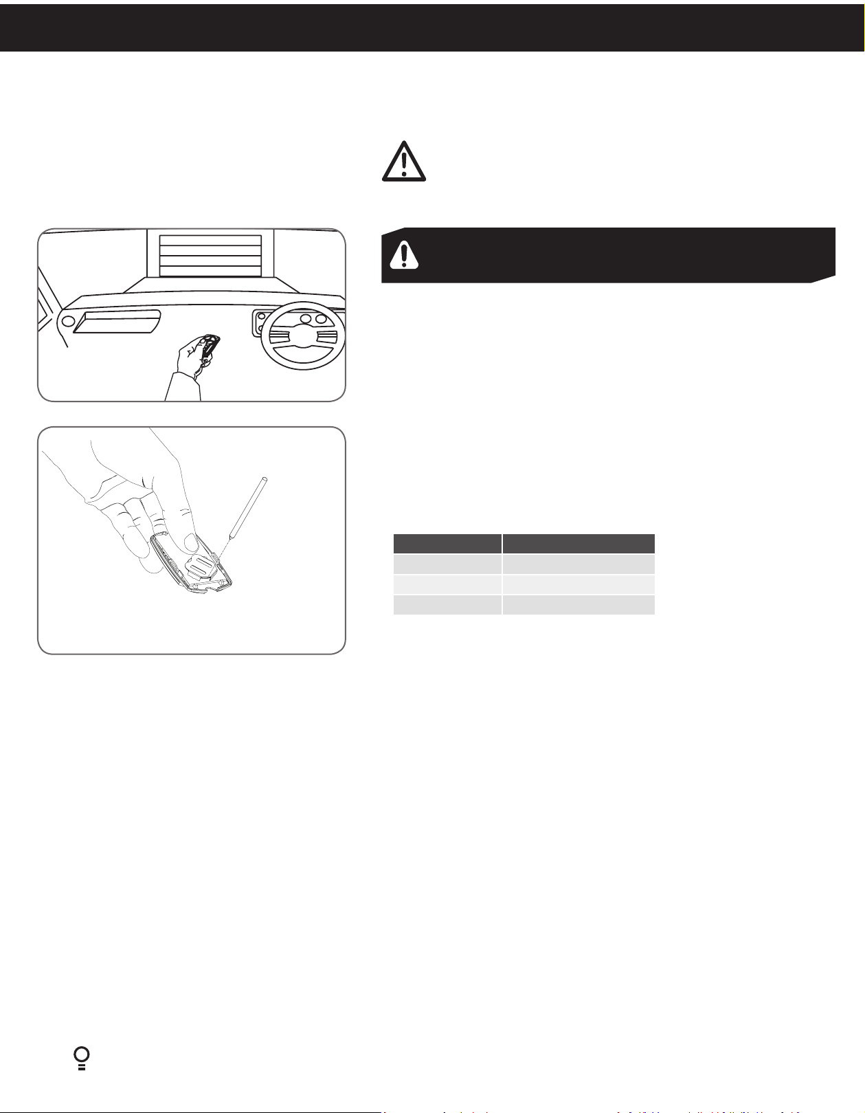
7.1.1 To Operate the opener:
a. Press the programmed transmitter button until your door begins to move
(usually 2 seconds). Make sure you can see the door when you use the
transmitter (Fig 7.1).
b. If you are in a vehicle you should aim the transmitter through your
windscreen as shown.
c. Check that the door is fully open or closed before you drive in or away.
d. If you press the transmitter whilst the door is moving the door will stop.
The next press of the transmitter will move the door in the opposite
direction.
7.1.2 Replacing the Battery: 3V Lithium Battery CR2032.
a. To test the battery is working, press and hold a transmitter button. Check
Light Status table to determine if battery needs replacing
Light Status Battery Status
Solid OK
Flashing Requires replacement
No light Requires replacement
Fig.7.2
b. Remove screw from back of cover.
c. Use screw driver to separate the transmitter casing to expose circuit
board.
d. Use a non-metallic object (e.g. pen) to remove the battery.
(Fig. 7.2).
22
GDO-8V3 Shed Master Instruction Manual
Page 23

© Copyright 2017
7.2 User Operating Controls
Button Function
1. OPERATE Opens/stops/closes the door
2. CODING LED (Red) Flashes when a code is being stored or when the transmitter button is pressed
3. DOOR CODE (Blue) Is used for storing or erasing transmitter buttons for door operation
4. PLUS (+) LED (Green) Illuminates and flashes as the door opens and remains on when the open limit position has
been reached.
5. DOOR STATUS LED (Yellow) Illuminates when Service is due.
6. MINUS (-) LED (Red) Illuminates and flashes as the door opens closes, and remains on when the close limit
position has been reached.
05
0203 04
01
06
Fig.7.3
7.3 Door Status Indicators
Door Status Indicators PLUS (+) LED (green) MINUS (-) LED (red) Beeper
Open On
Close On
Opening Flashing
Closing Flashing
Door travel stopped Flashing Flashing
Door obstructed when opening Flashing Beeps while door is
moving
Door obstructed when closing Flashing Beeps while door is
moving
Opener overloaded Alternating flashes Alternating flashes
Mains power interrupted Rapid flashes
Shed Master Instruction Manual GDO-8V3
Diamond PD Power Drive : Instruction Manual
23
Page 24

8. User Maintenance Instruction
WARNING! Run the Safety Testing procedures
MONTHLY in Section 6.9 to ensure garage door
is fit for use.
8.1 Door Maintenance
A poorly maintained door could cause fatal / serious injuries or
damage to property.
a. Frequently examine the door, particularly the cables, springs
and mountings for signs of wear, damage or imbalance. DO
NOT USE if repair or adjustment is needed since a fault in
the installation or an incorrectly balanced door may cause
injury.
b. Fasteners: Check all screws, nuts and bolts to ensure they
are secure.
c. Spring Tension: It is natural for springs to lose tension.
Should the door become hard to operate or completely
inoperative, contact a door professional.
d. Guide Tracks: Clean the internal sections of the guide tracks
every 3 - 6 months with a cloth dampened with mineral
turps or methylated spirits.
CAUTION! Frequently examine the installation, in
particular cables, springs and mountings, for signs of
wear, damage or imbalance. DO NOT USE if repair or
adjustment is needed since a fault in the installation or
an incorrectly balanced door may cause injury.
Adjustments should only be carried out by experienced
persons, as this function can be dangerous if not
performed under strict safety procedures.
WARNING! Failure to maintain your garage
door may void the warranty on your garage door
operator.
8.2 If You Need a Service Call
If the opener needs a service please call the dealer who installed
the garage door opener (their contact details are usually on a
sticker on the back of your garage door).
BEFORE CALLING you should have the following information to
assist in providing the appropriate service:
1. Has anything happened since the opener last operated OK,
e.g. a storm, a jolt to the door etc.?
2. What is the current light status on the opener?
3. Manually disengage the door (Section 5).
How easy is it to manually open and close the door?
4. What model is the opener? (Model no. information is located
at the rear of the opener)
5. Who installed the opener? (Dealer details should be on a
sticker on the back of your garage door)
6. When was it installed? (If known)
24
GDO-8V3 Shed Master Instruction Manual
Page 25

9. Troubleshooting
Symptom Possible cause Remedy
© Copyright 2017
The opener does not
work from the transmitter
One transmitter works
but the other/s do not
The motor is running
but the door remains
stationary
The transmitter range
varies or is restricted
The opener does not have power
The battery in the transmitter is flat
The opener has been put into
“Vacation Mode”
The transmitter button is not
programmed to operate the door.
Door Code LED is flashing yet the
opener is not working.
Faulty transmitter
Flat battery
The opener is disengaged Re-engage the opener
Variations are normal depending on
conditions e.g. temperature or external
interference
The battery life is exhausted
Position of the transmitter in the motor
vehicle
Plug a device of similar voltage (e.g. a hairdryer) into
the power point and check that it is OK
Replace the battery
Turn off “Vacation Mode”
(Section 6.12.2)
Code in the transmitter
Ensure the correct button on the transmitter is being
pressed.
Replace transmitter
Replace battery
Make sure you can see the door when you use the
transmitter.
Check the battery status by pressing a button (flashing
or no light requires battery to be changed)
Aim the transmitter through the windscreen.
The door reverses for no
apparent reason
The door stops or moves
very slowly.
The SERVICE LED has
started to flash and is
beeping numerous times
The Open (Green) LED
and MINUS (-) (Red) LED
are flashing alternatively
The Open (Green) LED
continues to flash
The MINUS (-) (Red) LED
continues to flash
This may occur occasionally from
environmental conditions such as areas
that are windy, dusty or have extreme
temperature changes.
If Safety beams are installed they may
be partially obstructed.
Garage door in poor condition e.g.
springs may be broken.
A Fault has been detected. The fault
will be active each time an attempt is
made to operate the door.
Opener is overloaded Check the doors operation by disengaging the motor
Door obstructed when opening Clear away any obstructions and test door opens
Door obstructed when closing
Ensure the door runs smoothly before increasing the
force pressure.
Ensure the beam path is not obstructed. Check the
Alignment.
Check the door’s operation.
Record opener function (How many beeps?) then
press the SET button once to reset the opener. If the
fault continues to be tripped contact your dealer for
support.
and ensuring the door runs smoothly. If necessary
make door adjustments or discontinue use and
contact your dealer for support.
correctly. (If door is damaged, contact your door
professionl).
Clear away any obstructions and test door closes
correctly. (If door is damaged, contact your door
professional).
Limits may be cleared
Remove all power sources. Wait till all lights are out
(10-15 secs), then reconnect power. If Red LED is
flashing, limits are not set. Reset Limits.
Shed Master Instruction Manual GDO-8V3
Diamond PD Power Drive : Instruction Manual
25
Page 26

10. Customer Agreement & Warranty
PLEASE READ THIS AGREEMENT CAREFULLY TO ENSURE THAT YOU UNDERSTAND EACH PROVISION. THIS AGREEMENT REQUIRES THE USE OF
ARBITRATION ON AN INDIVIDUAL BASIS TO RESOLVE DISPUTES, RATHER THAN JURY TRIALS OR CLASS ACTIONS, AND ALSO LIMITS THE REMEDIES
AVAILABLE TO YOU IN THE EVENT OF A DISPUTE.
This Agreement, the product manual, Limited Warranty terms below, terms and conditions, and terms of service for garage door opener products, features, and
applications (“Products”) not otherwise described herein that are posted on applicable ATA websites or devices, and any documents expressly referred to herein or
therein, make up the complete agreement between you and ATA and supersede any and all prior agreements and understandings related to the subject matter of
this Agreement.
WARRANTY PERIOD
MOTOR & PARTS 5 years / 10,000 cycles
which ever occurs first
ACCESSORIES
1 Year
(e.g Safety Beams)
CONSUMABLES
(e.g Batteries in remote control
transmitters and light bulbs and fuses)
This Warranty is to be read in conjuction with the owner’s copy of the installation instruction
manual.
LIMITED WARRANTY
1. The product will operate properly providing you comply with the instructions
concerning installation, operation, and maintenance and testing. Failure to
act in accordance with those instructions may void all or part of this limited
warranty.
2. The warranty periods for different parts of this product are set out in the table
above. If during the relevant warranty period, this product appears to contain
a defect in a component covered by this limited warranty, call your Retailer,
who will advise you how to disassemble it and to send in a suitably secured
packaging, pre-paid and insured, to a service center. Please include a brief
description of the problem and a dated proof-of-purchase receipt.
3. If ATA confirms the product is defective and covered by this limited warranty,
ATA will be repair or replace it (at ATA’s sole option) and return it to you, at no
cost to you. Defective parts will be repaired or replaced with new or factoryrebuilt parts at ATAs sole option. (You are responsible for any costs incurred in
removing and/or reinstalling the product or any component).
4. THIS WARRANTY EXCLUDES DAMAGE RESULTING FROM:
(A) NORMAL WEAR AND TEAR;
(B) ACCIDENTAL DELIBERATE OR NEGLIGENT DAMAGE OR DAMAGE CAUSE
BY INSECTS;
(C) BLOWN FUSES, ELECTRICAL SURGES, POWER SURGES OR POWER SPIKES;
(D) THEFT, FIRE, FLOOD, RAIN, WATER, LIGHTNING, STORMS OR ANY OTHER
ACTS OF GOD;
(E) ANY INSTALLATION, CONFIGURATION OR USE OF THE PRODUCT
CONTRARY TO THE INSTRUCTIONS SUPPLIED WITH THE PRODUCT;
(F) MAXIMUM CONTINUOUS OPERATING TIME EXCEEDING 1 MINUTE IN 10;
(G) THE OPERATING FORCE EXCEEDING 33LBS (150 NEWTON) WHEN MOVING
THE DOOR MANUALLY TO THE OPEN OR CLOSED POSITION (THE DOOR
THAT THE PRODUCT IS USED WITH SHOULD BE BALANCED IN SUCH A
WAY THAT THE USER IS ABLE TO OPEN OR CLOSE THE DOOR MANUALLY
USING A FORCE NOT GREATER THAN 150 NEWTON (33 LBS), OTHER THAN
TO INITIALLY CAUSE THE DOOR TO START MOVING, WHICH MAY REQUIRE
FORCE IN EXCESS OF THAT SPECIFIED IN THIS PARAGRAPH) ;
(H) DOOR SURFACE AREA AND/OR WEIGHT EXCEEDING 92FT2 AND 595LBS
RESPECTIVELY;
(I) THE DOOR USED WITH THE PRODUCT NOT BEING IN SAFE WORKING
ORDER AND CONDITION;
(J) REPAIRS WHICH ARE NOT AUTHORIZED BY ATA;
(K) ANY UNAUTHORIZED MODIFICATION TO THE PRODUCT OR ACTS OR
OMISSIONS OF ANY PERSON (INCLUDING SERVICE PROVIDERS APPROVED
BY ATA) OTHER THAN ATA;
(L) FAULTY OR UNSUITABLE WIRING IN THE BUILDING IN WHICH THE
PRODUCT IS INSTALLED;
(M) ANY COST OR EXPENSE RELATING TO THE RECALL OF THE
PRODUCT;
(N) INSTALLATION OF A RESIDENTIAL GARAGE DOOR OPENER IN A
COMMERCIAL OR INDUSTRIAL PREMISES OR IN A DWELLING OTHER
26
THAN A SINGLE-FAMILY DWELLING;
GDO-8V3 Shed Master Instruction Manual
Not covered
(O) RADIO OR ELECTRICAL INTERFERENCE; OR LACK OF AVAILABILITY OR
(I) DOOR SURFACE AREA AND/OR WEIGHT EXCEEDING 92FT2 AND
595LBS RESPECTIVELY;
(II) THE DOOR USED WITH THE PRODUCT NOT BEING IN SAFE WORKING
ORDER AND CONDITION
5. This Warranty is not transferable.
6. No additional warranty will apply for Products repaired during the relevant
warranty period.
7. For all Products repaired outside the warranty period charges may apply and
a six (6) month warranty that the Product will be free of any defects in material
and workmanship will apply from the date of return of the Product to you.
8. Where the Product is sold by any person other than ATA, except for the
warranty set out above, such person has no authority from ATA to give any
warranty or guarantee on ATA’s behalf in addition to the warranty set out
above.
9. LIMITATION ON LIABILITY AND DAMAGES EXCLUSION - EXCEPT
AS EXPRESSLY PROVIDED IN THIS LIMITED WARRANTY AND THE
USER TERMS, ATA MAKES NO REPRESENTATIONS, GUARANTEES,
CONDITIONS OR WARRANTIES, EITHER EXPRESS OR IMPLIED. ANY
OTHER STANDARDS OF PERFORMANCE, GUARANTEES, CONDITIONS
AND WARRANTIES ARE HEREBY EXPRESSLY EXCLUDED AND
DISCLAIMED TO THE FULLEST EXTENT PERMITTED BY LAW. THIS
DISCLAIMER AND EXCLUSION SHALL APPLY EVEN IF THE EXPRESS
LIMITED WARRANTY CONTAINED IN THE LIMITED WARRANTY AND
USER TERMS FAILS OF ITS ESSENTIAL PURPOSE.
10. ANY IMPLIED WARRANTIES THAT MAY BE IMPOSED BY LAW
SHALL BE LIMITED TO THE DURATION OF THE LIMITED WARRANTY
ABOVE. OTHERWISE THE REPAIR, REPLACEMENT, OR REFUND AS
PROVIDED UNDER SUCH EXPRESS LIMITED WARRANTY IS PROVIDED
IN LIEU OF ALL OTHER WARRANTIES, EXPRESS OR IMPLIED. TO THE
FULLEST EXTENT THESE DAMAGES MAY BE DISCLAIMED BY LAW,
ATA WILL IN NO EVENT BE LIABLE, WHETHER IN CONTRACT OR TORT
OR ANY OTHER LEGAL THEORY, INCLUDING WITHOUT LIMITATION
STRICT LIABILITY, GROSS NEGLIGENCE OR NEGLIGENCE, FOR ANY
DAMAGES IN EXCESS OF THE PURCHASE PRICE OF THE PRODUCT OR
FOR ANY DIRECT, INDIRECT, INCIDENTAL, SPECIAL, CONSEQUENTIAL
OR PUNITIVE DAMAGES OF ANY KIND REGARDLESS OF WHETHER ATA
WAS ADVISED OR THE POSSIBILITIES OF SUCH DAMAGES. ATA IS NOT
LIABLE FOR ANY CLAIM MADE BY A THIRD PARTY OR MADE BY YOU
FOR A THIRD PARTY.
TERMS RELATING TO THE USE AND LIMITATIONS OF SERVICE
1. WHAT ARE THE LIMITATIONS ON SERVICE AND LIABILITY?
a. Unless prohibited by law, the following limitations of liability apply. Service
may be interrupted, delayed, or otherwise limited for a variety of reasons,
including environmental conditions, unavailability of radio frequency
channels, system capacity, priority access by National Security and Emergency
Preparedness personnel in the event of a disaster or emergency, coordination
with other systems, equipment modifications and repairs, and problems with
the facilities of interconnecting carriers.
b. Additional hardware, software, subscription, credit or debit card, Internet
access from your compatible PC and/or special network connection may
be required and you are solely responsible for arranging for or obtaining all
such requirements. Some solutions may require third party products and/or
services, which are subject to any applicable third party terms and conditions
and may require separate purchase from and/or agreement with the third
party provider. ATA is not responsible for any consequential damages caused
in any way by the preceding hardware, software or other items/requirements
for which you are responsible.
c. Not all Services are available for purchase or use in all sales channels, in all
areas or with all devices. ATA is not responsible for loss or disclosure of any
sensitive information you transmit. ATA is not responsible for nonproprietary
services or their effects on devices.
Page 27

© Copyright 2017
2. INTELLECTUAL PROPERTY.
You must respect the intellectual property rights of ATA, our third-party content providers,
and any other owner of intellectual property whose protected property may appear on
any website and/or dialogue box controlled by ATA or accessed through the ATA’s
websites. Except for material in the public domain, all material displayed in association
with the Product is protected by copyright or trademarks. Except for personal, noncommercial use, this material may not be copied, downloaded, redistributed, modified
or otherwise exploited, in whole or in part, without the permission of the owner. The
ATA trademarks and logos are the exclusive property of ATA.
3. SEVERABILITY
If any provision of this Agreement is found to be unenforceable by a court
or agency of competent jurisdiction, the remaining provisions will remain in
full force and effect. The foregoing does not apply to the prohibition against
class or representative actions that is part of the arbitration clause; if that
prohibition is found to be unenforceable, the arbitration clause (but only the
arbitration clause) shall be null and void.
4. GOVERNING LAW
In the event of a dispute between you and ATA, Texas law, whether in
litigation or arbitration, shall govern that dispute and the interpretation
of this Agreement, except to the extent that such law is preempted by or
inconsistent with applicable federal law.
5. LANGUAGE
The original version of this Agreement is in the English language. Any
discrepancy or conflicts between the English version and any other language
version will be resolved with reference to and by interpreting the English
version.
HOW DO I RESOLVE DISPUTES WITH ATA?
1. DISPUTE RESOLUTION BY BINDING ARBITRATION
PLEASE READ THIS CAREFULLY. IT AFFECTS YOUR RIGHTS.
Most customer concerns can be resolved quickly and to the customer’s
satisfaction by calling our customer service department at (817)-873-5076.
In the unlikely event that ATA’s customer service department is unable to
resolve a complaint you may have to your satisfaction (or if ATA has not been
able to resolve a dispute it has with you after attempting to do so informally),
we each agree to resolve these disputes through binding arbitration or
small claims court instead of courts of general jurisdiction. Arbitration is
more informal than a lawsuit in court. Arbitration uses a neutral arbitrator
instead of a judge or jury, allows for more limited discovery than in court,
and is subject to very limited review by courts. Arbitrators can award the
same damages and relief that a court can award. Any arbitration under this
Agreement will take place on an individual basis; class arbitrations and class
actions are not permitted.
2. ARBITRATION AGREEMENT
1. You and ATA agree to arbitrate all disputes and claims between us. This
agreement to arbitrate is intended to be broadly interpreted. It includes, but
is not limited to:
• claims arising out of or relating to any aspect of the relationship between
us, whether based in contract, tort, statute, fraud, misrepresentation or any
other legal theory; and
• claims that may arise after the termination of this Agreement.
3. The arbitration will be governed by the Commercial Arbitration Rules and
the Supplementary Procedures for Consumer Related Disputes (collectively,
“AAA Rules”) of the American Arbitration Association (“AAA”), as modified
by this Agreement, and will be administered by the AAA. The AAA Rules
are available online at adr.org, by calling the AAA at 1-800-778-7879, or by
writing to the Notice Address. (You may obtain information that is designed
for non-lawyers about the arbitration process at att.com/arbitrationinformation.) The arbitrator is bound by the terms of this Agreement. All
issues are for the arbitrator to decide, except that issues relating to the scope
and enforceability of the arbitration provision are for the court to decide.
Unless ATA and you agree otherwise, any arbitration hearings will take place
in Texas]. If your claim is for $10,000 or less, we agree that you may choose
whether the arbitration will be conducted solely on the basis of documents
submitted to the arbitrator, through a telephonic hearing, or by an in-person
hearing as established by the AAA Rules.
4. The arbitrator may award declaratory or injunctive relief only in favor of the
individual party seeking relief and only to the extent necessary to provide
relief warranted by that party’s individual claim. YOU AND ATA AGREE THAT
EACH MAY BRING CLAIMS AGAINST THE OTHER ONLY IN YOUR OR ITS
INDIVIDUAL CAPACITY, AND NOT AS A PLAINTIFF OR CLASS MEMBER
IN ANY PURPORTED CLASS OR REPRESENTATIVE PROCEEDING. Further,
unless both you and ATA agree otherwise, the arbitrator may not consolidate
more than one person’s claims, and may not otherwise preside over any form
of a representative or class proceeding. If this specific provision is found to
be unenforceable, then the entirety of this arbitration provision shall be null
and void.
References to “ATA,” “you,” and “us” include our respective subsidiaries,
affiliates, agents, employees, predecessors in interest, successors and
assigns, as well as all authorized or unauthorized users or beneficiaries
of services or Products under this or prior Agreements between us. This
arbitration agreement does not preclude you from bringing issues to the
attention of federal, state, or local agencies. You agree that, by entering into
this Agreement, you and ATA are each waiving the right to a trial by jury or to
participate in a class action. Notwithstanding the foregoing, either party may
bring an individual action in small claims court.] This Agreement evidences
a transaction in interstate commerce, and the Federal Arbitration Act
governs the interpretation and enforcement of this provision. This arbitration
agreement shall survive termination of this Agreement.
2. A party who intends to seek arbitration must first send to the other, by
certified mail, a written Notice of Dispute (“Notice”). The Notice to ATA
should be addressed to: Office for Dispute Resolution, ATA,Vineyard Centre
II, 1452 Hughes Road, Grapevine, Texas 76051 (“Notice Address”). The
Notice must: (a) describe the nature and basis of the claim or dispute; and (b)
set forth the specific relief sought (“Demand”). If ATA and you do not reach
an agreement to resolve the claim within 30 days after the Notice is received,
you or ATA may commence an arbitration proceeding. During the arbitration,
the amount of any settlement offer made by ATA or you shall not be disclosed
to the arbitrator until after the arbitrator determines the amount, if any, to
which you or ATA is entitled. You may download or copy a form Notice and a
form to initiate arbitration at www.ata-america.com.
Shed Master Instruction Manual GDO-8V3
Diamond PD Power Drive : Instruction Manual
27
Page 28

Automatic Technology America
VIneyard Centre II, 1452 Hughes Road, Grapevine, Texas 76051, United States of America
P: +1 817 873 5076 W: www.ata-america.com
 Loading...