

Page 1
NAM-TRS372-MT-EN-C
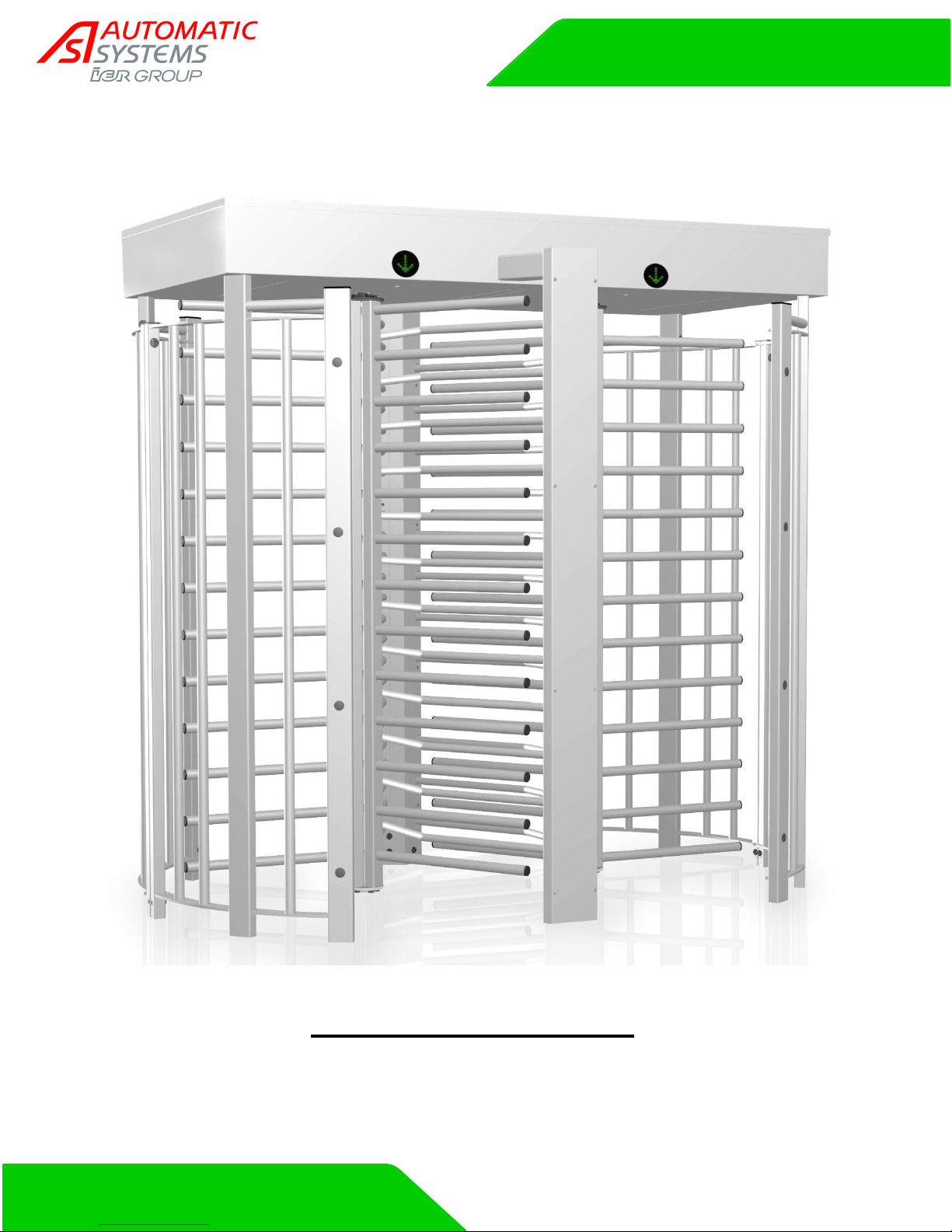
TRS 372
TECHNICAL MANUAL
Page 2
Revision
n°
Date
Written
by
Checked
by
Nature
A
2011-OCT-25
SSA
First edition.
B
2013-FEV-12
JPS
Change electrical diagram (CH6).
C
2015-03-10
JPNF
SSA
Figure corrections page 11-13-14
Document revisions
NAM-TRS372-MT-EN-C p2/38
The information in this document is the property of Automatic Systems and is confidential. The consignee withholds from using it for anything other than the use of the products or the execution of the
project to which they belong and withholds from communicating it to third parties without prior written agreement from Automatic Systems. Document subject to change without prior notice.
Page 3

Table of contents
1. SAFETY WARNINGS 4
2. INSTALLATION 5
2.1. Equipment storage before installation 5
2.2. List of tools required 5
2.3. Installation on finished ground surface (with template) 6
2.4. Installation with fixing frame (option) 8
2.5. Turnstile assembly 10
2.5.1. Fixed panel assembly 10
2.5.2. Central upright assembly 11
2.5.3. Plugs installation 12
2.5.4. Fixing the turnstile to the ground 13
2.5.5. Upper box section assembly 13
2.5.6. Canopy assembly (option) 15
2.5.7. Mobile comb assembly 16
2.5.8. Heel guard assembly (option) 17
2.6. Electrical connections 17
3. DESCRIPTION 18
3.1. Technical specifications 18
3.2. Operating modes 18
3.2.1. Mode descriptions 18
3.2.2. Power failure 18
3.3. Location of the components 19
3.4. Fixed panel 20
3.5. Mobile combs 20
3.6. Fixed combs 21
3.7. Upper box 22
3.8. Heating resistance (option) 23
3.9. Mechanical assembly 24
3.9.1. Modes 3 and 5 - Operating principle 25
3.9.2. Mode 4 – Operating principle 25
3.10. Pictograms 26
3.10.1. Orientation pictograms 26
3.10.2. Function pictograms 26
3.11. Control board 27
4. MAINTENANCE 34
5. TROUBLESHOOTING 35
6. ELECTRICAL DIAGRAMS 36
6.1. Control board terminal block assignment 37
NAM-TRS372-MT-EN-C p3/38
The information in this document is the property of Automatic Systems and is confidential. The consignee withholds from using it for anything other than the use of the products or the execution of the
project to which they belong and withholds from communicating it to third parties without prior written agreement from Automatic Systems. Document subject to change without prior notice.
Page 4

1. SAFETY WARNINGS
This manual must be made available to everyone working on the equipment: installer, maintenance
operator, end user…
This equipment is solely intended to control pedestrian access. Operating it for any other purpose entails
risks for the user and may jeopardize the integrity of the equipment. Automatic Systems’ responsibility
may not be invoked for damages resulting from inappropriate use of the equipment.
Specifically, the turnstile is not intended for:
- People with reduced mobility.
- Unaccompanied children.
- Managing a continuous flow of more than twenty (20) people per minute.
This equipment must not be installed in an explosive area.
Do not add accessories that are not original equipment or that have not been approved by the
manufacturer (contact between different metals may cause galvanic corrosion that can accelerate the
deterioration of the equipment).
The contractor must respect all local standards and regulations when installing the equipment.
All operations performed on the equipment must be undertaken by qualified personnel. All operations that
are not authorized or that are carried out on this product by an unqualified technician shall automatically
invalidate the manufacturer’s warranty.
Access to the mechanism must be limited to personnel informed of the electrical and mechanical risks
incurred by negligent handling. The access door to mechanism must be locked after every operation
performed.
Be certain to switch off the electrical power supply on the circuit breaker (ch. 2.6. ) when opening the
housing.
The equipment is configured in a "minimal risk" mode for its users. All modifications of the parameters
must be undertaken by experienced and qualified personnel and in no way can be deemed the
responsibility of Automatic Systems.
NAM-TRS372-MT-EN-C p4/38
The information in this document is the property of Automatic Systems and is confidential. The consignee withholds from using it for anything other than the use of the products or the execution of the
project to which they belong and withholds from communicating it to third parties without prior written agreement from Automatic Systems. Document subject to change without prior notice.
Page 5

2. INSTALLATION
2.1. Equipment storage before installation
Prior to installation, be careful to avoid all physical impacts to the equipment. Keep it in its original packaging
and store it in a dry location. Make sure it is protected from dust, heat and harsh weather.
Extreme temperatures of storage: -30 to +80°C [-22 to 176°F].
2.2. List of tools required
Wrench set.
Ratchet set.
500 g hammer.
Percussion drill + drill bit Ø15mm x 100mm (if fixed to the ground with template).
Spirit level.
Forklift.
NAM-TRS372-MT-EN-C p5/38
The information in this document is the property of Automatic Systems and is confidential. The consignee withholds from using it for anything other than the use of the products or the execution of the
project to which they belong and withholds from communicating it to third parties without prior written agreement from Automatic Systems. Document subject to change without prior notice.
Page 6
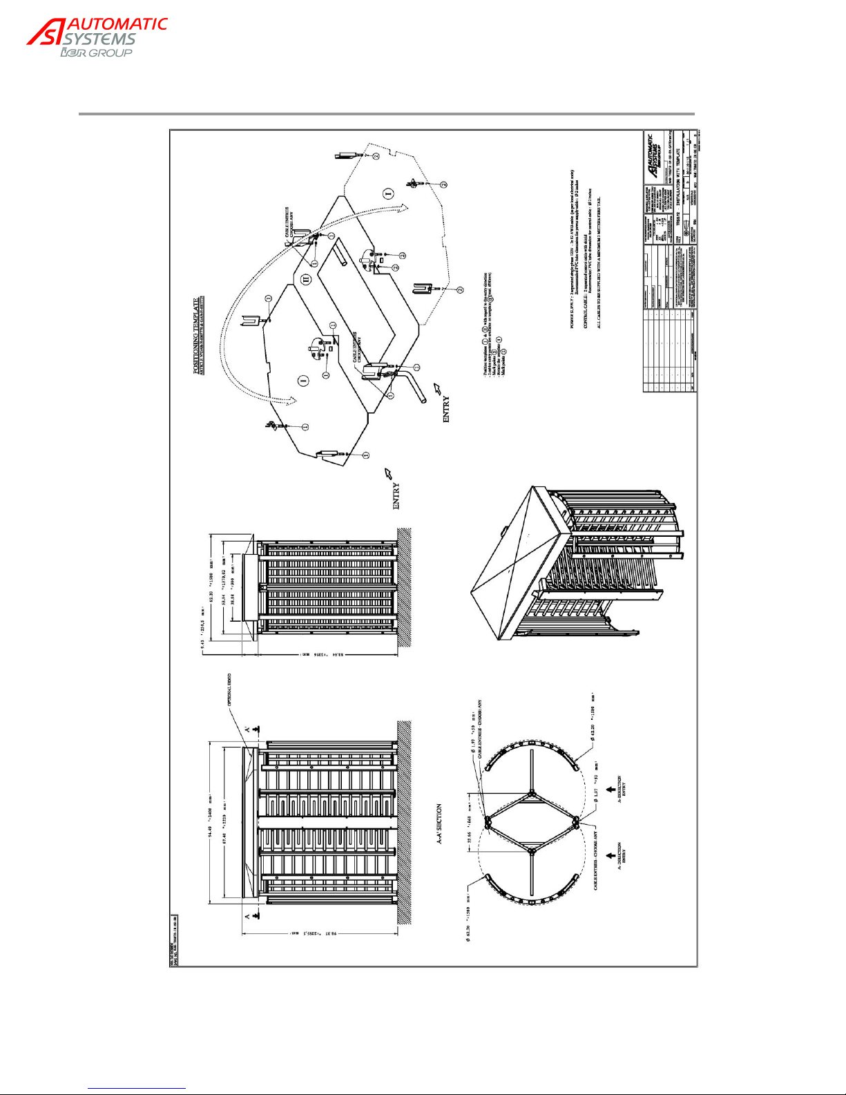
2.3. Installation on finished ground surface (with template)
NAM-TRS372-MT-EN-C p6/38
The information in this document is the property of Automatic Systems and is confidential. The consignee withholds from using it for anything other than the use of the products or the execution of the
project to which they belong and withholds from communicating it to third parties without prior written agreement from Automatic Systems. Document subject to change without prior notice.
Page 7
21
1. Conduit installation for the passage of cables and remote control devices (as seen in implementation
drawings) should be planned in advance.
Remember that the cable ends must extend 4m [13ft] above ground level, as electrical connections are
done in the upper section of the full-height turnstile.
2. Ensure that the surface on which the full-height turnstile is to be installed is perfectly flat (without any
irregularities) and made of concrete or other non-flammable material.
3. Following the instructions presented in the Installation Drawing, use your drilling template to mark the
location of the various drilling holes.
4. If you chose to use the anchoring bolts provided by Automatic Systems, bore holes that have a diameter
of 15 mm and are 85 mm deep into the surface.
Caution: Although the anchoring bolts provided by Automatic Systems are compatible with most
configurations, the complete fixing process must be adapted to the environment and nature of the ground
on which the full-height turnstile is to be installed. All civil work must be approved and validated by a
knowledgeable engineer..
The equipment must be fixed to the ground prior to being used!
Automatic Systems cannot be held responsible for accidents or damages resulting from a faulty anchoring
installation.
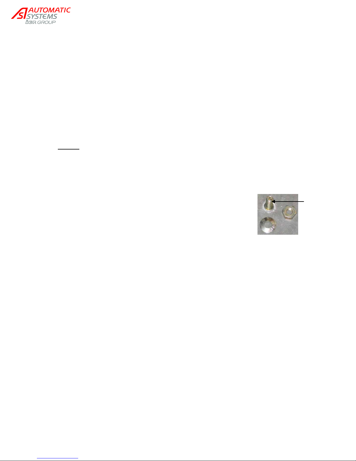
5. Put the anchoring bolts (21) in place. Pre-tighten the nuts so as to fix the
expanding anchoring bolt into the ground. Proceed then to remove the nuts
previously tightened in order to be able to install the fixing brackets later on.
NAM-TRS372-MT-EN-C p7/38
The information in this document is the property of Automatic Systems and is confidential. The consignee withholds from using it for anything other than the use of the products or the execution of the
project to which they belong and withholds from communicating it to third parties without prior written agreement from Automatic Systems. Document subject to change without prior notice.
Page 8
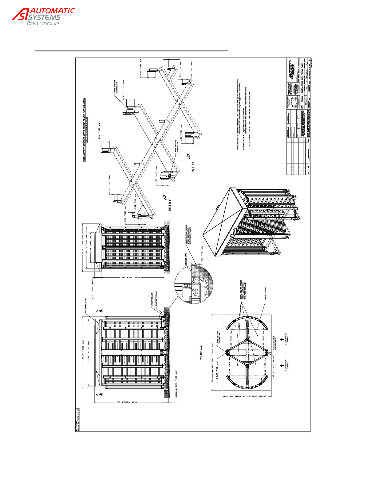
2.4. Installation with fixing frame (option)
NAM-TRS372-MT-EN-C p8/38
The information in this document is the property of Automatic Systems and is confidential. The consignee withholds from using it for anything other than the use of the products or the execution of the
project to which they belong and withholds from communicating it to third parties without prior written agreement from Automatic Systems. Document subject to change without prior notice.
Page 9

Following the instructions presented in the implementation drawing:
1. Conduit installation for the passage of cables and remote control devices should be planned in
advance. Remember that the cable ends must extend 3m [10ft] above ground level, as electrical
connections are done in the upper section of the full-height turnstile.
2. Dig a hole in the ground for the installation of the concrete slab.
3. Using the hardware provided, assemble the various parts of the fixing frame.
4. Verify the interaxial spacing between the different crossbars of the fixing frame.
5. Place the fixing frame in the hole you have just dug:
- Ensuring that you follow the direction of passage.
- Making sure that you run the conduits for the cables and remote control devices through the
uprights to be installed.
- Verifying that the fixing brackets are buried in the ground as indicated in the implementation
drawing (the painted part of the brackets must be left unburied).
6. Pour standard concrete in the hole, making sure to smooth it out.
7. Leave to dry for about one week.
NAM-TRS372-MT-EN-C p9/38
The information in this document is the property of Automatic Systems and is confidential. The consignee withholds from using it for anything other than the use of the products or the execution of the
project to which they belong and withholds from communicating it to third parties without prior written agreement from Automatic Systems. Document subject to change without prior notice.
Page 10
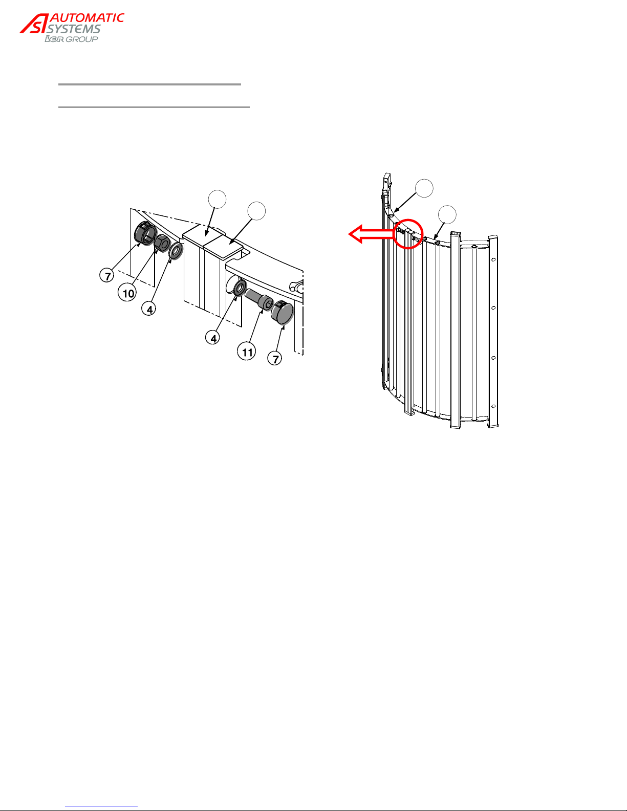
K L 3
2
2. Right curved part
3. Left curved part
4. Flat washer DIN 125 M12.
7. Plug (ext Ø 30 .9 mm)
10. Nut DIN 985 M12.
11. Screw DIN 912 M12x30.
2.5. Turnstile assembly
2.5.1. Fixed panel assembly
Proceed to assemble uprights K and L of left (3) and right (2) curved parts.
Repeat this assembly process with the 2 curved parts remaining.
NAM-TRS372-MT-EN-C p10/38
The information in this document is the property of Automatic Systems and is confidential. The consignee withholds from using it for anything other than the use of the products or the execution of the
project to which they belong and withholds from communicating it to third parties without prior written agreement from Automatic Systems. Document subject to change without prior notice.
Page 11
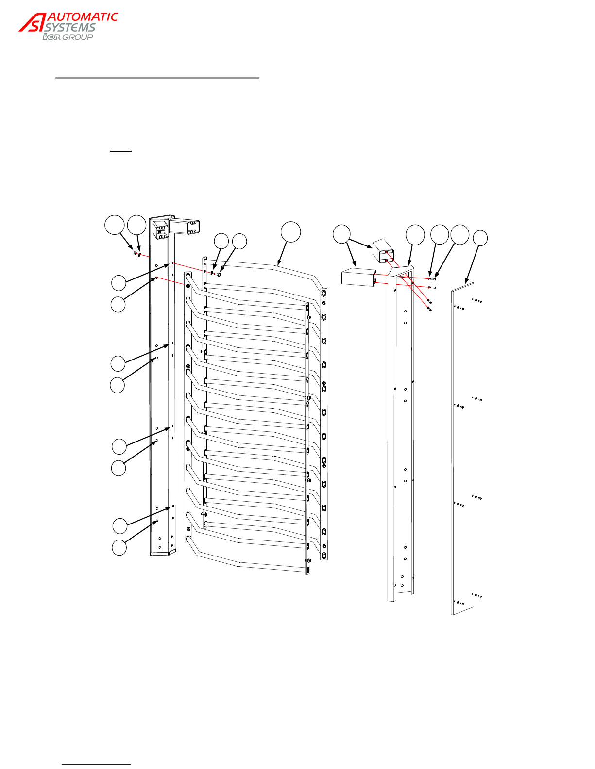
4. Flat washer DIN 125 M12.
6. ½ round head M12x30.
12. Fixed comb
14. Grower washer DIN 127 M12.
15. Nut DIN 934 M12
40. Central upright
43. Screw DIN 933 M6 x 20
44. Tooth lock washer DIN 6798 M6
45. Central upright arm
43
44
6
4
14
15
T
45
40
12
U
V U V U V U V
2.5.2. Central upright assembly
Unscrew the covers (T) protecting the central uprights (40) and remove them.
Using the bolts (43) and washers (44) provided, fix the arms (45) to the central uprights (40).
Attach the fixed combs (12) to the central uprights (40) by means of the bolts, washers and nuts (6),
(4), (14), (15) supplied.
Note: In order not to knock against one another, the 2 mobile combs have to be staggered. (cf.
ch.2.5.7. ). Thus, the 2 fixed combs must also be slightly out of line. To that end, one of the 2 fixed
combs must be attached through the upper holes (U), and the second one through the lower holes (V).
Remember to run the electric cables (ch. 2.5.4. ) through the central uprights before you screw the covers
(T) back.
NAM-TRS372-MT-EN-C p11/38
The information in this document is the property of Automatic Systems and is confidential. The consignee withholds from using it for anything other than the use of the products or the execution of the
project to which they belong and withholds from communicating it to third parties without prior written agreement from Automatic Systems. Document subject to change without prior notice.
Page 12
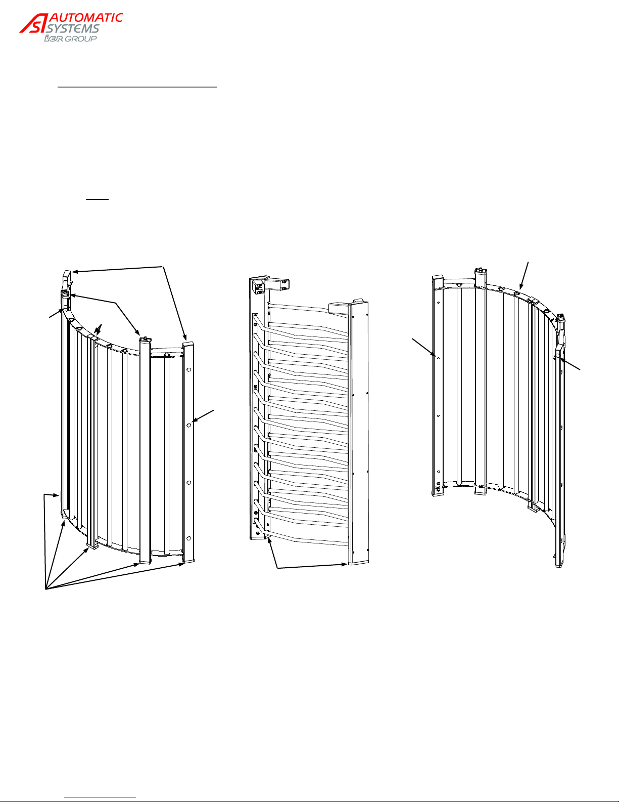
16
16 8 9 7 7
13
7
41
No plug on
vertical tubes’
tips.
7. Plug (ext Ø 30.9)
8. Square plug
9. Rectangular plug
16. Upright protector
13. Plug
41. Central upright protector
2.5.3. Plugs installation
Install the upright protectors (16) on the lower ends of the 10 uprights holding the fixed panel.
Remember to also put protectors on the upper parts of the 4 topmost uprights.
Repeat the aforementioned operation with the 2 central upright protectors (41).
Close the upper parts of the remaining uprights by means of the plugs provided (8) and (9).
Once the whole structure is firmly fixed to the ground, (cf. next chapter), proceed to block out the
lateral openings with the plugs (7) and (13).
Note: The tips of the fixed panel vertical tubes must stay open.
NAM-TRS372-MT-EN-C p12/38
The information in this document is the property of Automatic Systems and is confidential. The consignee withholds from using it for anything other than the use of the products or the execution of the
project to which they belong and withholds from communicating it to third parties without prior written agreement from Automatic Systems. Document subject to change without prior notice.
Page 13
K
L
M
N R S
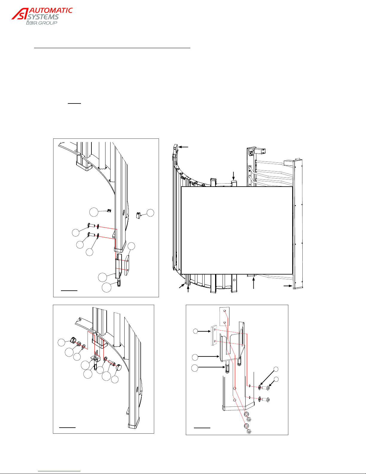
4. Flat washer DIN 125 M12.
5. Ground fixing clamp.
6. ½ round head screw M12x30.
7. Plug (ext Ø 30 .9 mm).
10. Nut DIN 985 M12.
11. Screw DIN 912 M12x30.
13. Round plug.
14. Grower washer DIN 127 M12.
19. Fixing bracket.
20. Fixing bracket.
21. Anchoring bolt B15/30.
42. Double fixing bracket.
Fig. C
4
42
21
Fig. A
7
5
21
19
4
6
6
13
Fig. B
7
11
4
21
20
4
10
7
2.5.4. Fixing the turnstile to the ground
Fix the brackets (19), (20) and (42) to the anchoring bolts (21) (cf. implementation drawing, ch. 2.3. ).
Note: The fixing brackets are already part of the fixing frame; it is therefore unnecessary to install
additional ones if this option is chosen.
Run the electric cables through the central uprights (R) and (S). The, proceed to close the uprights and
fix them as shown in fig. C: start by inserting the bolts (6) and washers (4) through the central upright, in
the fixing clamp (5). Place the upright on the double fixing bracket (42) and tighten the bolts.
Note: In order to prevent corrosion, ensure that the uprights do not come in direct contact with the
concrete.
Fix the end uprights (M) and (N) as indicated in fig. A.
Fix the central uprights (K) and (L) as indicated in fig. B.
NAM-TRS372-MT-EN-C p13/38
The information in this document is the property of Automatic Systems and is confidential. The consignee withholds from using it for anything other than the use of the products or the execution of the
project to which they belong and withholds from communicating it to third parties without prior written agreement from Automatic Systems. Document subject to change without prior notice.
Page 14
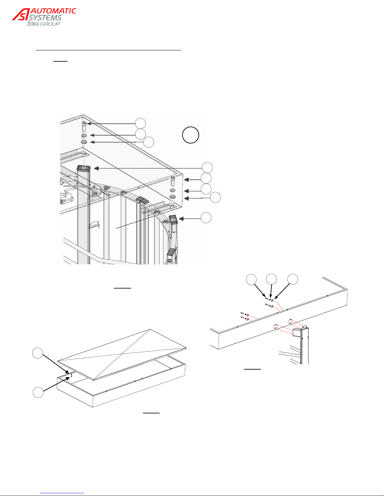
4. Flat washer DIN 125 M12.
11. Screw DIN 912 M12x30.
14. Grower washer DIN 127 M12.
29. Nut DIN 985 M6.
30. Flat washer DIN 9021 M6.
43. Screw DIN 933 M6 x 20
44. Tooth lock washer DIN 6798 M6
Fig. D
43
44
30
Fig. E
Fig. F
30
29
4 x
11
14 4 P
11
14
4
Q
2.5.5. Upper box section assembly
Note: The upper box section is of significant weight and must be handled by at least two (2) people.
Attach the upper box section to uprights (P) and (Q) of the curved parts (fig. D) of the turnstile.
Fix the central uprights to the upper box section (fig. E). Make sure to run the electric cables through
the upper housing.
Install the roof on the upper box (fig. F).
NAM-TRS372-MT-EN-C p14/38
The information in this document is the property of Automatic Systems and is confidential. The consignee withholds from using it for anything other than the use of the products or the execution of the
project to which they belong and withholds from communicating it to third parties without prior written agreement from Automatic Systems. Document subject to change without prior notice.
Page 15
Line of silicon at junction
(A) STAINLESS STEEL NUT A4 DIN934 M6
(B) STAINLESS STEEL FLAT WASHER DIN125 M6
(C) STAINLESS STEEL TOOTH LOCK WASHER
DIN6798 M6 JZ
(D) STAINLESS STEEL HEXAGON 1/2 ROUND HEAD
BOLT M6x16
A B C D 14 x
28 x
14 x
14 x
B
Line of silicon on contact
face
655mm [25.79in]
655mm [25.79in]
450mm [17.71in]
450mm [17.71in]
55mm [2.16in]
58mm
[2.28in]
171,5
[6.75in]
58
55mm [2.16in]
58mm [2.28in]
X X X
X
X
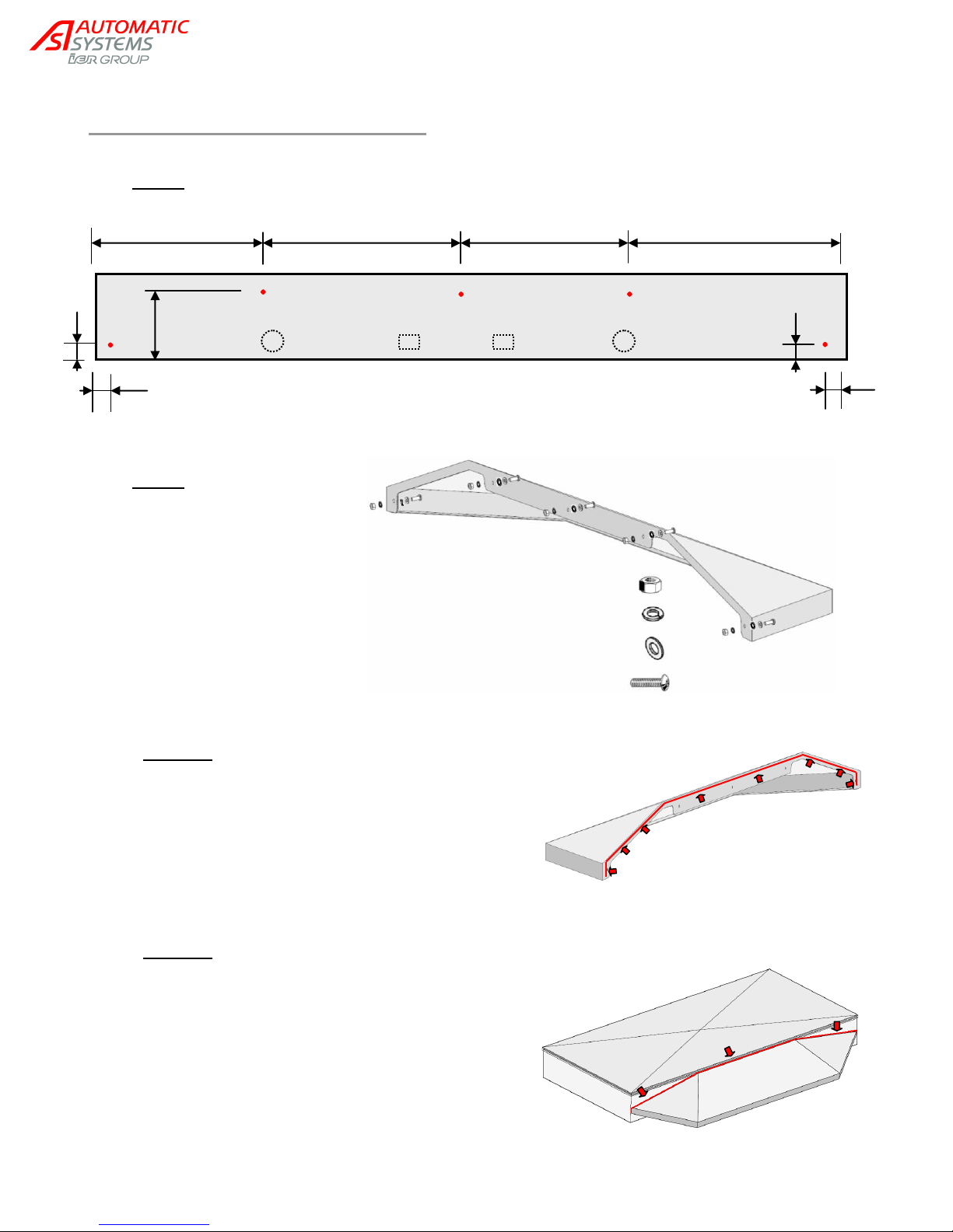
2.5.6. Canopy assembly (option)
Step 1: Drill five (5) 8mm [5/16’’] holes (marked X), on both sides of the upper box.
Step 2:
Solution 1:
- Before you proceed to fix the canopy to the housing,
put a line of silicon on the face that comes in contact
with the upper box.
- Using the hardware provided, attach each canopy to
the upper section.
Solution 2:
- Using the hardware provided, attach each canopy to
the upper section.
- Put a line of silicon at the junction where the canopy
and upper box meet.
NAM-TRS372-MT-EN-C p15/38
The information in this document is the property of Automatic Systems and is confidential. The consignee withholds from using it for anything other than the use of the products or the execution of the
project to which they belong and withholds from communicating it to third parties without prior written agreement from Automatic Systems. Document subject to change without prior notice.
Page 16
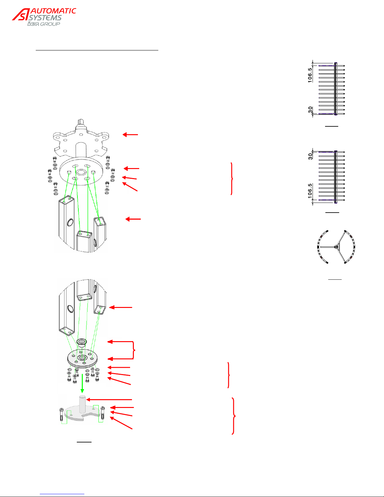
Fig. J
Fig. K
Fig. L
Upper flange assembly on
the mechanism
Cover with Loctite glue
before tightening
Mobile comb
Mobile comb
3-arm lower flange assembly
For installation on finished
ground surface only.
For installation with fixing frame
(option), use the axle (already
assembled on the fixing frame).
cover with Loctite glue
before tightening
Fig. M
Screw DIN 933 M12x30.
Flat washer DIN 125 M12
Tooth lock washer DIN 798 M12
Screw DIN 933 M12x25.
Flat washer DIN 125 M12
Tooth lock washer DIN 798 M12
Cap nut A4 DIN 1587 M10
Anchoring bolt B15/30
Lower axle
Flat washer M10
2.5.7. Mobile comb assembly
Start with the passageway which has the fixed comb closest to the ground (cf. ch.
2.5.2. ). Position the mobile combs so as to have to lowest bar as close to the
ground as possible (30 mm [1.18in] ) (fig. J).
Direct the mobile combs of the second passageway so as to have the lowest bar
as far from the ground as possible (106,5 mm [4.19in]) (fig. K).
Adjust the mobile combs on the upper and lower flanges so as to close the
passageway (cf. implementation drawing & fig. L) and assemble (fig. M).
NAM-TRS372-MT-EN-C p16/38
The information in this document is the property of Automatic Systems and is confidential. The consignee withholds from using it for anything other than the use of the products or the execution of the
project to which they belong and withholds from communicating it to third parties without prior written agreement from Automatic Systems. Document subject to change without prior notice.
Page 17
120 V
Ground
Neutral
E G F
2.5.8. Heel guard assembly (option)
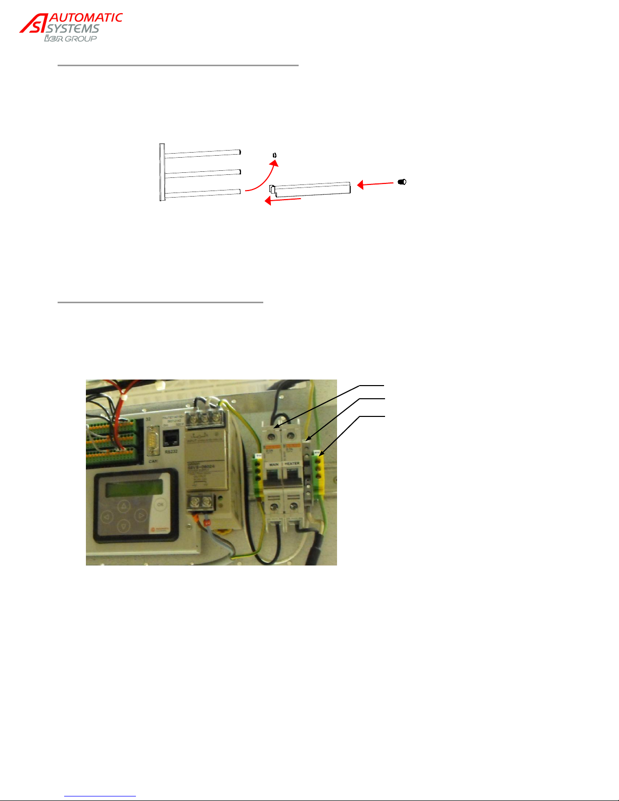
1. For each mobile comb, remove the plug (G) from the tube that is closest to the ground.
2. Slide the heel guard (E) onto the tube.
3. Close by means of provided plug (F) (larger): article EMB-E-0010418.
2.6. Electrical connections
Power supply and command cables are provided by the user and are described in the implementation
drawing.
If the command cables are different from the ones recommended, they must be separated from the power
supply cables in order to avoid interference. Thus, they must run through different uprights.
1. Connect the power supply to the breaker as shown.
Protect the upstream line with a 16-A breaker.
2. Connect the options (card readers, etc.) according to the electrical diagrams.
3. Engage the circuit breaker.
4. Set the control board according to the added options ("OPTIONS" group).
5. Send a passage command and verify that the turnstile is working properly: unlocking, rotation of the obstacle,
locking.
NAM-TRS372-MT-EN-C p17/38
The information in this document is the property of Automatic Systems and is confidential. The consignee withholds from using it for anything other than the use of the products or the execution of the
project to which they belong and withholds from communicating it to third parties without prior written agreement from Automatic Systems. Document subject to change without prior notice.
Page 18

3. DESCRIPTION
3.1. Technical specifications
Double gate rotating turnstile.
For each passageway: rotating obstacle with 3 combs positioned at 120° from one another.
Net weight: 618 kg (including 2 x 90 kg for the upper box sections).
Power supply per lane (only for a turnstile equipped with a control board): single phase 120 VAC-60 Hz
– Nominal power consumption: 70 W.
AS1300 control board circuits: 24V DC
Operating temperature: from -10 to +50°C [14°F to 122°F].
Max. relative humidity : 95%, no condensation.
Mechanical locking of obstacle withstands a 1500 Nm torque.
Flow: 15 to 20 passages per minute per lane, depending on the reaction time of the reader.
Obstacle goes back to its initial position in less than 1.5 seconds
MCBF (mean cycles between failures), respecting the recommended maintenance: 1.000.000.
MTTR (average repair time): 20 minutes.
Surface treatment:
- Galvanized internal mechanical parts.
- Galvanized rotating obstacle, fixed comb and walls + 2 coats of pale grey paint RAL7038
(except for galvanized-finishing models).
- Upper box section treated by electrophoresis + 2 coats of pale grey paint RAL7038.
3.2. Operating modes
3.2.1. Mode descriptions
For each direction of passage, the different configurations are as follows:
1. Free access (obstacle turns freely).
2. Permanently locked (obstacle blocked mechanically).
3. Locked, but unlocked in case of power failure.
4. Electrically controlled (free, locked, passage subject to authorization) and locked mechanically in
case of power failure.
5. Electrically controlled (free, locked, passage subject to authorization) and unlocked in case of
power failure.
A A5-B3 passageway is thus configured to operate in mode 5 for direction A (entry) and in mode 3 for
direction B (exit).
Only turnstiles configured in mode 3, 4 or 5 (for at least one direction of passage) are equipped with a
control board.
3.2.2. Power failure
The key for mechanical unlocking (option) allows for the manual
unlocking of the turnstile when the turnstile is configured to be locked
during power failure. This feature can be applied in 1 or both passage
way directions according to the selected option.
NAM-TRS372-MT-EN-C p18/38
The information in this document is the property of Automatic Systems and is confidential. The consignee withholds from using it for anything other than the use of the products or the execution of the
project to which they belong and withholds from communicating it to third parties without prior written agreement from Automatic Systems. Document subject to change without prior notice.
Page 19
LED passageway lighting
Orientation pictograms
Roof
Upper box section,
including:
- 2 control boards
- 2 circuit breakers
- 2 mechanical assemblies
- 1 nameplate
Fixed panel
Fixing frame
(option)
Fixed combs
Mobile combs
Central upright
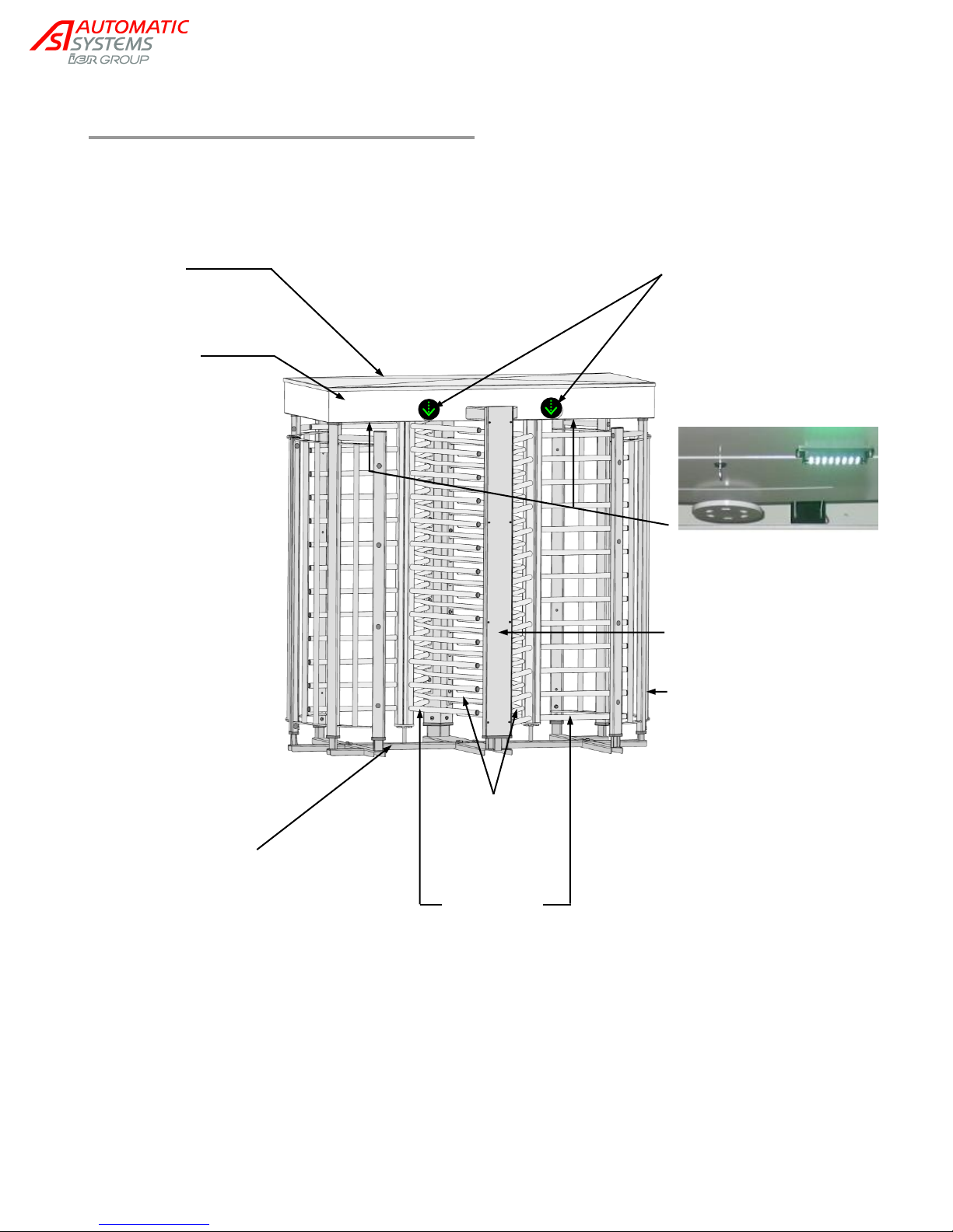
3.3. Location of the components
NAM-TRS372-MT-EN-C p19/38
The information in this document is the property of Automatic Systems and is confidential. The consignee withholds from using it for anything other than the use of the products or the execution of the
project to which they belong and withholds from communicating it to third parties without prior written agreement from Automatic Systems. Document subject to change without prior notice.
Page 20
Heel guard (option)
3.4. Fixed panel
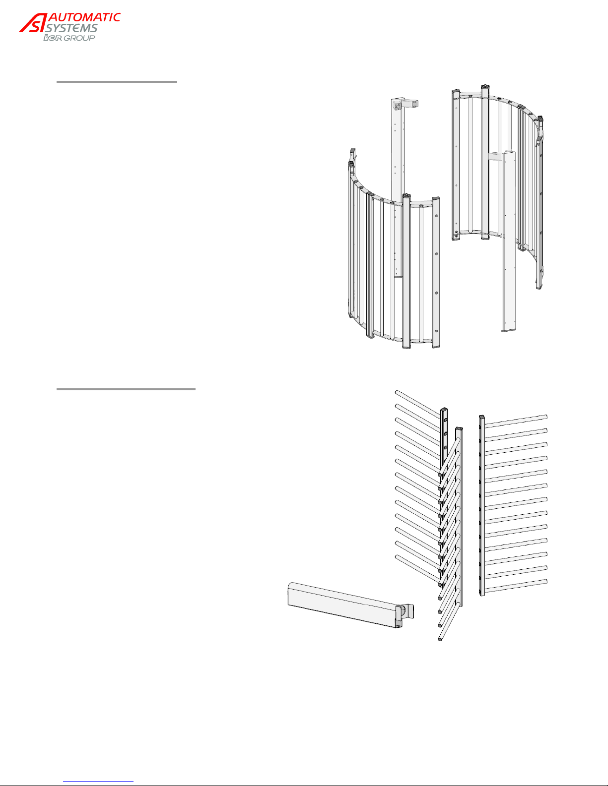
Fixed modular panel made of painted steel, with curved
parts circumscribing the passageway.
Central uprights are used to run the various electric
cables.
The panel is bolted to the ground or to the fixing frame.
3.5. Mobile combs
The rotating obstacle consists of 2 x 3
mobile combs positioned at 120° from one
another.
The tubes that are closest to the ground
may be equipped with heel guards
(optional) that prevent users from getting
their feet caught between the lowest tube
and the ground.
NAM-TRS372-MT-EN-C p20/38
The information in this document is the property of Automatic Systems and is confidential. The consignee withholds from using it for anything other than the use of the products or the execution of the
project to which they belong and withholds from communicating it to third parties without prior written agreement from Automatic Systems. Document subject to change without prior notice.
Page 21
3.6. Fixed combs
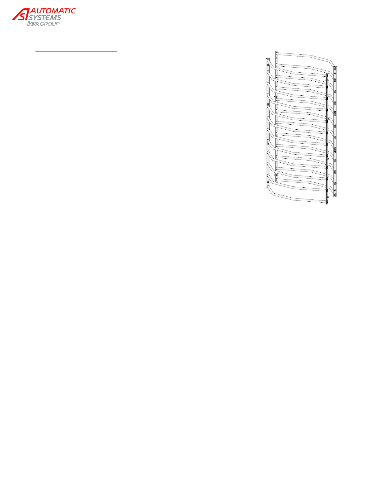
The fixed combs limit the access to one half of the turnstile, for each of
the two passageways.
NAM-TRS372-MT-EN-C p21/38
The information in this document is the property of Automatic Systems and is confidential. The consignee withholds from using it for anything other than the use of the products or the execution of the
project to which they belong and withholds from communicating it to third parties without prior written agreement from Automatic Systems. Document subject to change without prior notice.
Page 22
10
11
12
11
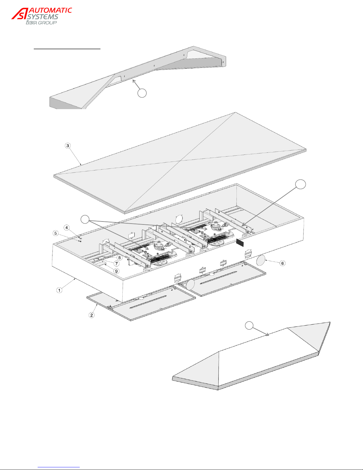
1. Upper box.
2. Doors with key locks for access to mechanism.
3. Diamond point roof for evacuation of water.
4. Washer for fixing the roof.
5. Nut for fixing the roof.
6. Knockout for pictogram cut-out.
7. Washer for fixing knockout 9.
8. Nut for fixing knockout 9.
9. Knockout for lighting cut-out (under box).
10. Mechanical assemblies.
11. Canopy (option).
12. Nameplate.
3.7. Upper box
NAM-TRS372-MT-EN-C p22/38
The information in this document is the property of Automatic Systems and is confidential. The consignee withholds from using it for anything other than the use of the products or the execution of the
project to which they belong and withholds from communicating it to third parties without prior written agreement from Automatic Systems. Document subject to change without prior notice.
Page 23
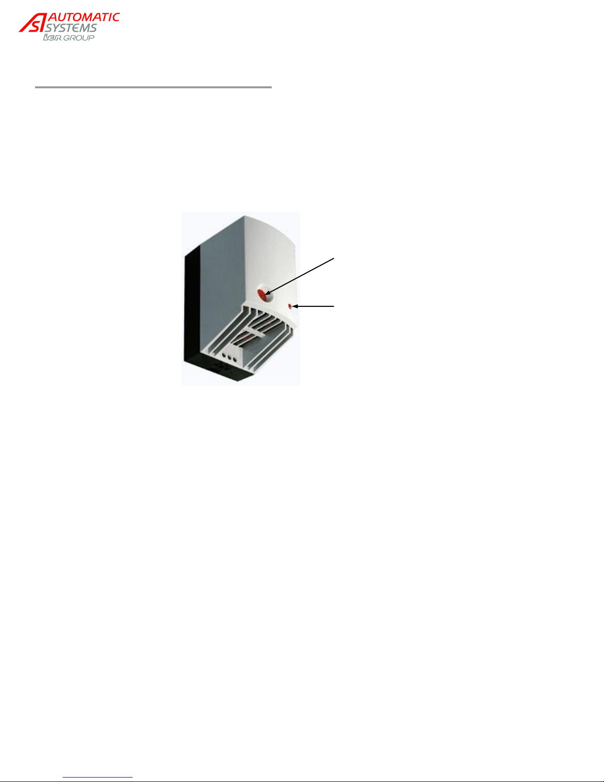
Thermostat
Function control light
3.8. Heating resistance (option)
Located inside the upper box, the fan heater prevents the formation of condensation and ensures an even
temperature in enclosures.
The integrated thermostat is used to set the desired temperature while the high performance axial fan
provides forced air circulation.
Heating power adjusts to ambient temperature (±550 W at 20°C [68°F]).
NAM-TRS372-MT-EN-C p23/38
The information in this document is the property of Automatic Systems and is confidential. The consignee withholds from using it for anything other than the use of the products or the execution of the
project to which they belong and withholds from communicating it to third parties without prior written agreement from Automatic Systems. Document subject to change without prior notice.
Page 24
B C D
F G H
K
L M N
A
E J P
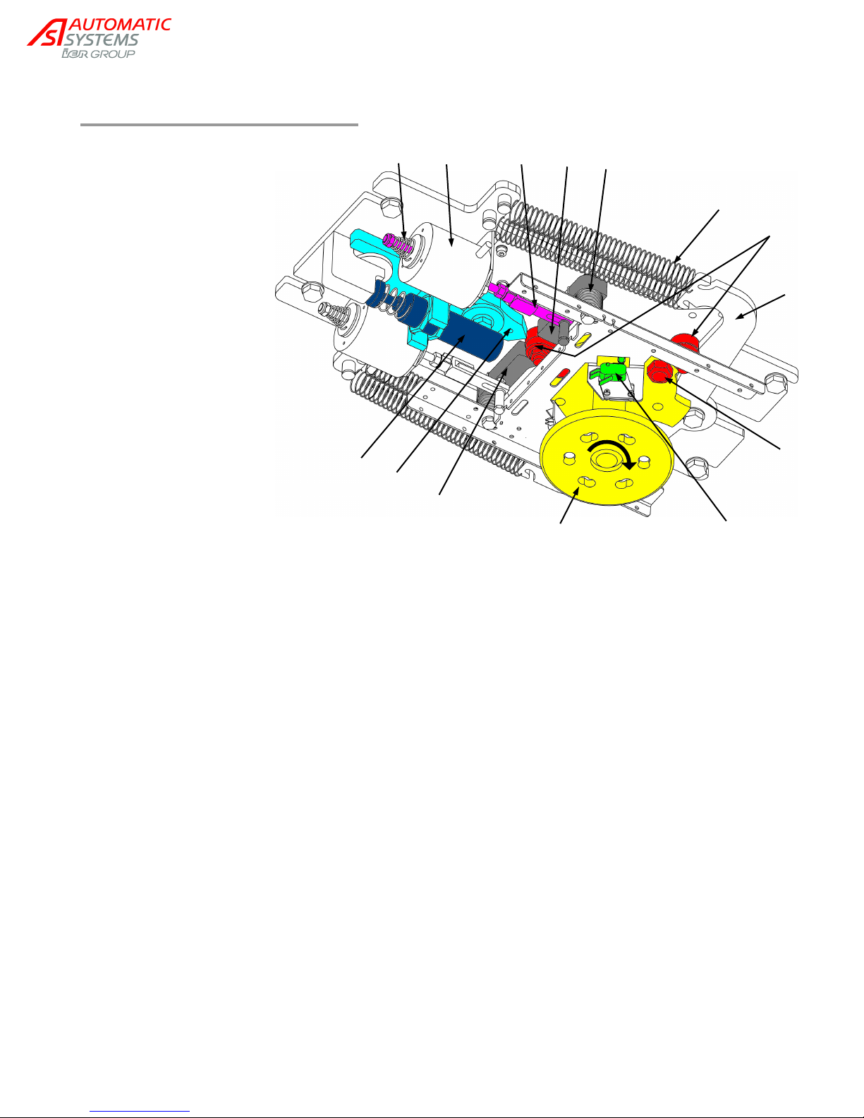
A. Electromagnet.
B. Connecting rod.
C. Release spring.
D. Mobile comb bolt.
E. Rotor.
F. Rollers.
G. Compensating arm.
H. Compensating arm release
springs.
J. Limit switch.
K. Bolt release spring.
L. Mobile comb bolt.
M. Shock absorber cam.
N. Hydraulic shock absorber.
P. Limit switch cam.
3.9. Mechanical assembly
NAM-TRS372-MT-EN-C p24/38
The information in this document is the property of Automatic Systems and is confidential. The consignee withholds from using it for anything other than the use of the products or the execution of the
project to which they belong and withholds from communicating it to third parties without prior written agreement from Automatic Systems. Document subject to change without prior notice.
Page 25
1 3 2 1 3 2 1 3 2
Fig. a
Fig. b
Fig. c
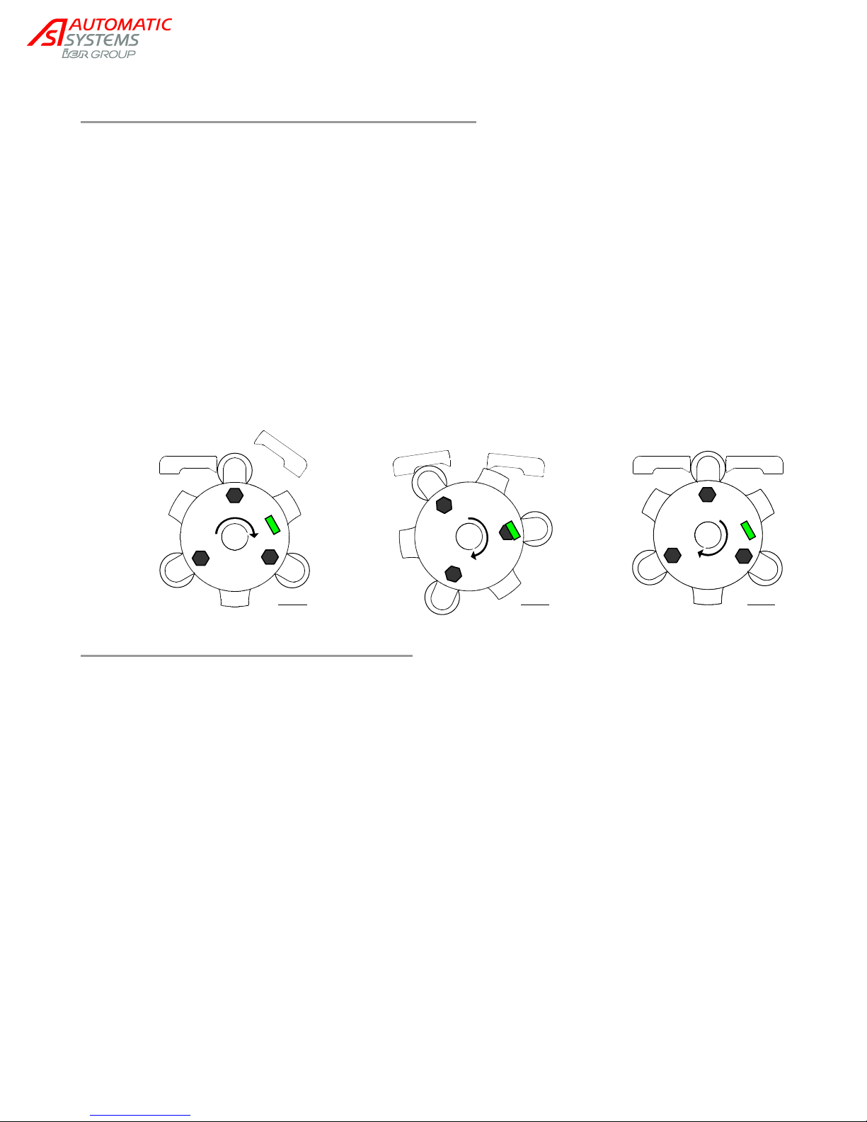
3.9.1. Modes 3 and 5 - Operating principle
In these modes, the obstacle is unlocked in case of power failure.
At rest, the electromagnet (A) is under voltage. Its connecting rod (B) compresses the release spring (C) in order
to bring the mobile comb bolt (D) into the closed position.
When a passage is authorized (by a card reader, a remote control desk, etc.), power supply to the electromagnet
is cut off. The release spring (C) then pulls, by means of the connecting rod (B), on the mobile comb bolt (D) and
unlocks the obstacle (Fig.a).
By pushing lightly on the obstacle, the user activates the rotor (E) (which turns, in this case, clockwise).
At the same time:
- The roller (F) pushes on the compensating arm (G). Its release springs (H) bring the rotor back to the
rest position when the obstacle is released.
- The limit switch cam (P) activates the limit switch (J), which powers up the electromagnet and drives
the connecting rod back (B) to the bolt (D). The mobile comb bolt then closes up under the action of the
release spring (K) (Fig.b).
- The next roller (F) presses against bolt (L), lodges itself between the 2 mobile comb bolts and pushes
on cam (M) of hydraulic shock absorber (N), which reduces its movement. The roller is then blocked by
bolt (D), and the obstacle is mechanically locked (Fig.c).
3.9.2. Mode 4 – Operating principle
In this mode, the obstacle is locked in case of power failure.
At rest, the electromagnet (A) is not charged. The release spring (C) (in this case, on the connecting
rod (B) side) pushes the rod towards the mobile comb bolt, in order to bring it in the closed position.
When a passage is authorized, the charged electromagnet compresses the release spring (C) in order
to pull, by means of the connecting rod (B), on the mobile comb bolt (D) and therefore unlock the
obstacle.
The remaining steps are identical to the preceding modes.
NAM-TRS372-MT-EN-C p25/38
The information in this document is the property of Automatic Systems and is confidential. The consignee withholds from using it for anything other than the use of the products or the execution of the
project to which they belong and withholds from communicating it to third parties without prior written agreement from Automatic Systems. Document subject to change without prior notice.
Page 26
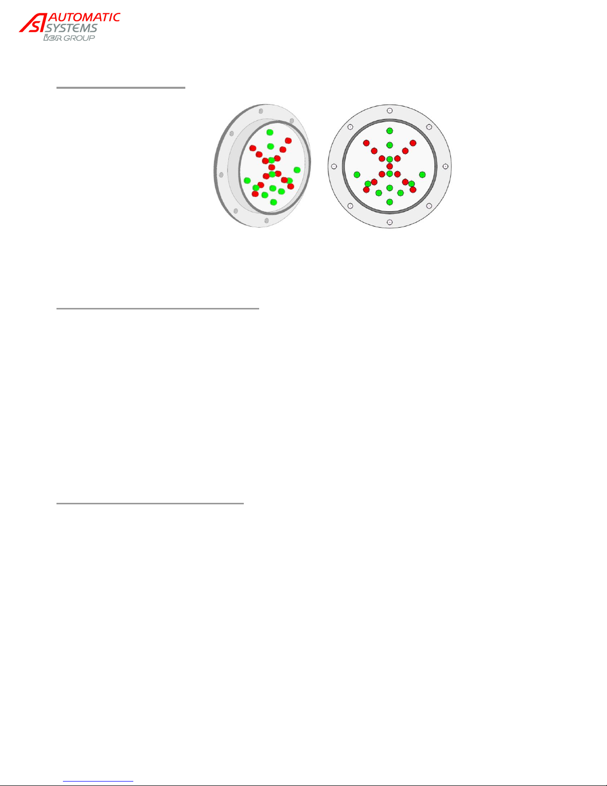
3.10. Pictograms
Pictograms mounted on the housing can operate according to the two (2) modes described below, depending
on the electrical connections and their parameterization in the control board.
3.10.1. Orientation pictograms
Orientation pictograms indicate the status of the passageway, and thus help to orientate the user
approaching the turnstile.
Apparatus Out of Service: X in both directions
Apparatus In Evacuation: in both directions
Apparatus In Service (for each direction of passage):
- Controlled Mode:
- Free Mode:
- Locked Mode: X
3.10.2. Function pictograms
Function pictograms indicate the functional status of the passageway to the user (for each direction):
passage authorized or unauthorized.
Locked Mode: X
Free Mode:
- If passage under way in opposite direction: X
- If not:
Controlled Mode:
- At rest: Pictogram turned off or X, according to the status of "Idle Fct Picto" parameter of
"Options" menu.
- If passage under way in opposite direction: X
- If passage authorization:
NAM-TRS372-MT-EN-C p26/38
The information in this document is the property of Automatic Systems and is confidential. The consignee withholds from using it for anything other than the use of the products or the execution of the
project to which they belong and withholds from communicating it to third parties without prior written agreement from Automatic Systems. Document subject to change without prior notice.
Page 27
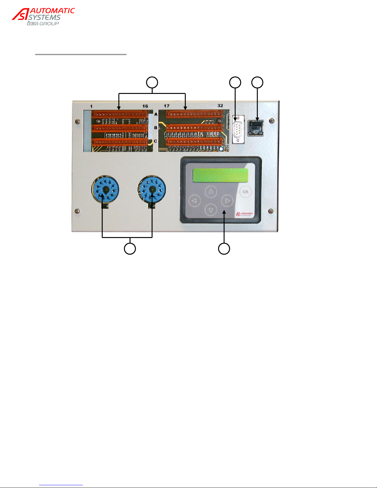
1 5 4 3 2
3.11. Control board
1. Input/Output terminal block (see terminal assignments, ch. “Electrical diagrams”).
2. DB9 (CAN BUS) connector.
3. RJ45 (RS232) connector.
4. Presence sensor connectors (not used for the TRS37x).
5. Display.
NAM-TRS372-MT-EN-C p27/38
The information in this document is the property of Automatic Systems and is confidential. The consignee withholds from using it for anything other than the use of the products or the execution of the
project to which they belong and withholds from communicating it to third parties without prior written agreement from Automatic Systems. Document subject to change without prior notice.
Page 28
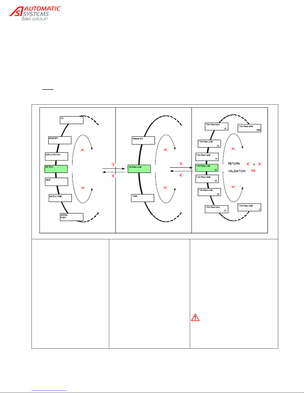
Menus are displayed in capital
letters on the top line, starting
with the first character of the
LCD.
Hold ▲ or ▼ for a few seconds
to leave the PRDSTD screen
and access the other menus.
Only the first letter of each word in
the parameters is a capital. They
are displayed on the top line
starting with the second character
of the LCD (i.e., there is a space
in front). At the end of the top line,
the parameter unit is displayed if
there is one.
A question mark (?) preceding the
parameter indicates that it is ready to
be modified.
The current value of the parameter
appears on the second line.
A star (*) below a parameter
indicates that it is the default value
(set in the factory).
To validate a modification, press the
OK key.
Store the modifications to
avoid losing them in the
event of a power outage
("MEMORY" "Save" “MEM1”
or “MEM2”).
The control board is the interface between the user and the full-height turnstile. It manages every operation
the TRS performs, including every optional action.
The navigation of the display menus is based on an architecture using drop-down menus with three levels:
MENUS PARAMETERS VALUES.
Moving from one level to another is achieved via the ◄ ► keys and navigation inside those levels by means
of the ▲ ▼ keys (press for a few seconds to go from the at-rest screen to another menu). Validating
parameter changes is done by pressing the OK button.
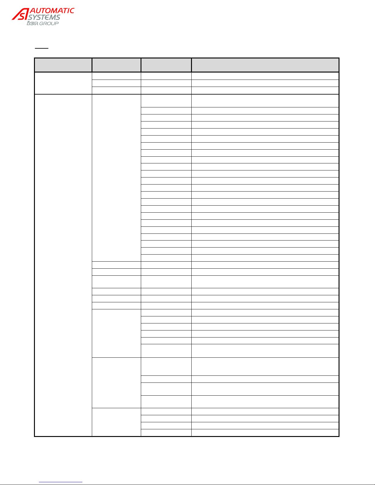
Note: Below is a simplified version of the menus of the control board. For a more detailed description of all
available functions and their parameters, please refer to the control board manual (available on request).
NAM-TRS372-MT-EN-C p28/38
The information in this document is the property of Automatic Systems and is confidential. The consignee withholds from using it for anything other than the use of the products or the execution of the
project to which they belong and withholds from communicating it to third parties without prior written agreement from Automatic Systems. Document subject to change without prior notice.
Page 29
GROUP
Parameter
Values
Description
PRDSTD - TRS360
Software Ver
0E 00 04 00 00
Version number of the program implemented in the control board.
◄ Left arrow key
Choice of language for menus. OK to validate.
OK key
Reader simulation (direction A then B).
OPERATION
Status
Display of the 100 last major events, with the date and time of
their occurrence (access to previous events with ► and ▲ keys).
No Diag
No diagnosis.
Power Up
Power on.
Power Down
Power off.
Short Circuit
Detection of short-circuit on the digital outputs.
Save Mem1
Manual saving of the values to Memory 1.
Save Mem2
Manual saving of the values to Memory 2.
Load Default
Loading of default values.
Load Mem1
Manual loading of values from Memory 1.
Load Mem2
Manual loading of values from Memory 2.
Time Adjust
Change of date and time.
Access Level Chg
Change of access level ("OPTION ► "Code").
Download Chg Lv1
Level 1 modification to program.
Download Chg Lv2
Level 2 modification to program.
Download Chg Lv3
Level 3 modification to program.
Reset Counters
Zeroing of counter 2.
In Service
Apparatus in service.
Out Of Service
Apparatus out of service.
Emergency
Apparatus in Evacuation mode (free in both directions).
Test
Apparatus in Test mode.
Maintenance
Apparatus in Maintenance mode.
Default LSA
Limit switch A defect. The turnstile remains in service.
Default LSB
Limit switch B defect. The turnstile remains in service.
Temperature
Display of temperature within casing.
Counter 1
Total number of passages in Directions A and B.
Counter 2
Total number of passages in Directions A and B since last
reset to zero.
Reset counter 2
Yes
Zeroing of counter 2.
Autoriz. A nº
Number of authorizations in progress in Direction A.
Autoriz. B nº
Number of authorizations in progress in Direction A.
Gate State
Indicates the current status of the apparatus.
Emergency
Apparatus in evacuation mode (free in both directions).
Test
Apparatus in Test mode.
Maintenance
Apparatus in Maintenance mode.
In Service
Apparatus in service (configuration in “EXPLOITATION” group).
Out of service
Apparatus out of service (locked in both directions):
command received on Input DI5.
Pass A State
Indicates the status in which the apparatus is when it is in service,
for this direction of passage. The configuration is carried out in the
“EXPLOITATION” group.
Locked
Obstacle locked: passage in this direction impossible.
Free
Obstacle unlocked: passage in this direction free and without
control.
Controlled
The obstacle is unlocked to release the passage, once authorized
by the card reader.
Pass B State
Same as “Pass A State”, for Direction B.
Locked
Free
Controlled
Note: Parameters of the control board have already been set in factory according to ordered configuration.
The most common functions are in bold.
NAM-TRS372-MT-EN-C p29/38
The information in this document is the property of Automatic Systems and is confidential. The consignee withholds from using it for anything other than the use of the products or the execution of the
project to which they belong and withholds from communicating it to third parties without prior written agreement from Automatic Systems. Document subject to change without prior notice.
Page 30
GROUP
Parameter
Values
Description
TIMINGS
No Passage
Delay allowed for user to pass through the turnstile
(=time allowed for the obstacle to reach the limit switch after
opening command).
Passage Info
Duration of the passage information impulse.
No Pass Info
Duration of the passage information impulse.
Fraud Info
Duration of the fraud information impulse.
OUTPUT FUNCTIONS
Relay 1
Each output can provide one of the following pieces of
information:
LED Lighting
LED lighting activated by the light sensor.
LSB Error
Direction B limit switch sensor has not been reached before the
no-passage time-out.
LSA Error
Direction A limit switch sensor has not been reached before the
no-passage time-out.
Fraud AB
Limit switch activated without prior Open command.
Fraud B
Direction B limit switch detection not preceded by an Open
command.
Fraud A
Direction A limit switch detection not preceded by an Open
command.
No Passage B
No detection on limit switch within the time limit following an Open
command in Direction B.
No Passage A
No detection on limit switch within the time limit following an Open
command in Direction A.
Pass B IP NC
Passage in Direction B in progress (Signal NC).
Pass B IP NO
Passage in Direction A in progress (Signal NO).
Pass A IP NC
Passage in Direction A in progress (Signal NC).
Pass A IP NO
Passage in Direction A in progress (signal NO).
Passage B NC
Passage in Direction B completed (Signal NC).
Passage B NO
Passage in Direction B completed (Signal NO).
Passage A NC
Passage in Direction A completed (Signal NC).
Passage A NO
Passage in Direction A completed (Signal NO).
Red Fct Icon B
Function pictogram command in Direction B: red indicator light.
Grn Fct Icon B
Function pictogram command in Direction B: green indicator light.
Red Fct Icon A
Function pictogram command in Direction A: red indicator light.
Grn Fct Icon A
Function pictogram command in Direction A: green indicator light.
Red Ori Icon B
Orientation pictogram command in Direction B: red indicator light.
Grn Ori Icon B
Orientation pictogram command in Direction B: green indicator
light.
Red Ori Icon A
Orientation pictogram command in Direction A: red indicator light.
Grn Ori Icon A
Orientation pictogram command in Direction B: green indicator
light.
Solenoid B
Command of the electromagnet of Direction B.
Solenoid A
Command of the electromagnet of Direction A.
None
No signal.
Relay 2
Same as Relay 1
Relay 3
Same as Relay 1
Relay 4
Same as Relay 1
Relay 5
Same as Relay 1
Relay 6
Same as Relay 1
Output 7
Same as Relay 1
Output 8
Same as Relay 1
Output 10
Same as Relay 1
Output 11
Same as Relay 1
Output 12
Same as Relay 1
Output 13
Same as Relay 1
Output 14
Same as Relay 1
Output 15
Same as Relay 1
NAM-TRS372-MT-EN-C p30/38
The information in this document is the property of Automatic Systems and is confidential. The consignee withholds from using it for anything other than the use of the products or the execution of the
project to which they belong and withholds from communicating it to third parties without prior written agreement from Automatic Systems. Document subject to change without prior notice.
Page 31
GROUP
Parameter
Values
Description
I/O
Input 1
Status of the digital inputs:
DI8, DI7, DI6, DI5, DI4, DI3, DI2, DI1.
Input 2
Status of the digital inputs:
DI16, DI15, DI14, DI13, DI12, DI11, DI10, DI9.
Input 3
Status of the digital inputs:
0, 0, 0, 0, 0, 0, DI18, DI17
Output 1
Status of the digital outputs:
DO8, DO7, DO6, DO5, DO4, DO3, DO2, DO1.
Output 2
Status of the digital outputs:
0, DO15, DO14, DO13, DO12, DO11, DO10, DO9.
AnalogIn 1
Value of the analogue input AI1 (x10mV).
AnalogIn 2
Value of the analogue input AI2 (x10mV).
AnalogOut 1
Value of the analogue output AO1 (x10mV).
AnalogOut 2
Value of the analogue output AO2 (x10mV).
MEMORY
Load
Default
Loading of the default values of the parameters.
Mem2
Loading of the values from Memory 2.
Mem1
Loading of the values from Memory 1.
Save
Mem2
Saving of the values to Memory 2.
Mem1
Saving of the values to Memory 1.
EXPLOITATION
Direction A
Ctrl panel
Direction A passage configured via the control panel.
Locked
Direction A passage always closed (even if there is an Open
command).
Free
Direction A passage always allowed (Open command not
necessary).
Controlled
Direction A passage subject to authorization (see Reader):
opens if there is an Open command.
Direction B
Ctrl panel
Direction B passage configured via the control panel.
Locked
Direction B passage always closed (even if there is an Open
command).
Free
Direction B passage always allowed (Open command not
necessary).
Controlled
Direction B passage subject to authorization (see Reader):
opens if there is an Open command.
Out Of Service
In Service
Apparatus in service: functions according to the mode
defined in the “Direction A” and “Direction B” parameters.
Out Of Service
Apparatus out of service: locked in both directions.
NAM-TRS372-MT-EN-C p31/38
The information in this document is the property of Automatic Systems and is confidential. The consignee withholds from using it for anything other than the use of the products or the execution of the
project to which they belong and withholds from communicating it to third parties without prior written agreement from Automatic Systems. Document subject to change without prior notice.
Page 32
GROUP
Parameter
Values
Description
OPTIONS
Code
-32768 to 32767
Code giving access to the Technician or Constructor level
parameters..
Language
Deutsch
Choice of the menu language: German.
Français
Choice of the menu language: French.
English
Choice of the menu language: English.
Idle Fct Picto
Off
Choice of display of the function pictogram when it is at rest:
off.
Red
Choice of display of the function pictogram when it is at rest:
red cross.
Thermostat °C
-10 to 100
Temperature beneath which the heating element is
engaged.
Electro Heating
Activated
Activates the electromagnets when the temperature
descends below the limit set at the “Thermostat °C”, which
maintains some warmth in the immediate environment of the
electromagnets.
Deactived
Heating by electromagnets deactivated.
Memo reader A
Yes
Storage by the reader of the Open commands given in
Direction A.
Memo reader B
Yes
Storage by the reader of the Open commands given in
Direction B.
Electromagnet A
A4
Assembly of the electromagnet used for Direction A:
mode 4 (= locked when not powered).
A5
Assembly of the electromagnet used for Direction A:
mode 5 (= unlocked when not powered).
Electromagnet B
B4
Assembly of the electromagnet used for Direction B:
mode 4 (= locked when not powered).
B5
Assembly of the electromagnet used for Direction B:
mode 5 (= unlocked when not powered).
Fct Reader
Combined Mode
This operating mode combines the following two modes. If
an impulse is given, the apparatus functions in impulse
mode, if not it functions in maintained mode. Any signal that
occurs before detection of the limit switch or the end of the
no-passage time-out is regarded as an impulse.
Hold Mode
Passage managed by the reader: the passage is freed for as
long as the input reader is activated.
Pulse Mode
Passage managed by the AS1300: each reader impulse,
which can be memorized, frees the access for a passage. As
soon as the passage is carried out, the obstacle is locked.
Reader NO
Yes
Reader operation in Direction A and B (active in high status):
signal NO (Normally Open).
No
Reader operation in Direction A and B (active in low status):
signal NC (Normally Closed).
No Pass Limit
0 to 1000
Maximum number of consecutive no-passages before
indicating that the limit switch is defective.
TEST
Test Mode
Wiring
Wiring check of the AS1300 outputs.
Alternate Mode
Alternation of the following two modes.
Direction B
Successive lockings/unlockings of Direction B passage.
Direction A
Successive lockings/unlockings of Direction A passage.
Communication
Menu
Sending of complete menu to external PC.
Stack Watch
Sending of stack values to external PC.
Diag. Extract.
Sending of diagnostic table to external PC.
Param. Extrac.
Sending of parameter values to external PC.
DATE & TIME
Year
0 to 99
Setting of year
Month
1 to 12
Setting of month
Day
1 to 31
Setting of day
Hour
0 to 23
Setting of hour
Minute
0 to 59
Setting of minutes
Second
0 to 59
Setting of seconds
NAM-TRS372-MT-EN-C p32/38
The information in this document is the property of Automatic Systems and is confidential. The consignee withholds from using it for anything other than the use of the products or the execution of the
project to which they belong and withholds from communicating it to third parties without prior written agreement from Automatic Systems. Document subject to change without prior notice.
Page 33
GROUP
Parameter
Values
Description
SERIAL PORT
Modbus Address
Definition of parameters for Modbus communication.
Com1 Baudrate
Com1 Parity
Debug Modbus
Test Modbus
LIGHT SENSOR
Value
0 to 100
Value measured by light sensor (option).
Trigger
0 to 100
Value for which the lighting is switched on/off.
Delay On
0 to 9999
Delay before activation of LED lighting.
Delay Off
0 to 9999
Delay before deactivation of LED lighting.
NAM-TRS372-MT-EN-C p33/38
The information in this document is the property of Automatic Systems and is confidential. The consignee withholds from using it for anything other than the use of the products or the execution of the
project to which they belong and withholds from communicating it to third parties without prior written agreement from Automatic Systems. Document subject to change without prior notice.
Page 34
Each
month
(see note
opposite)
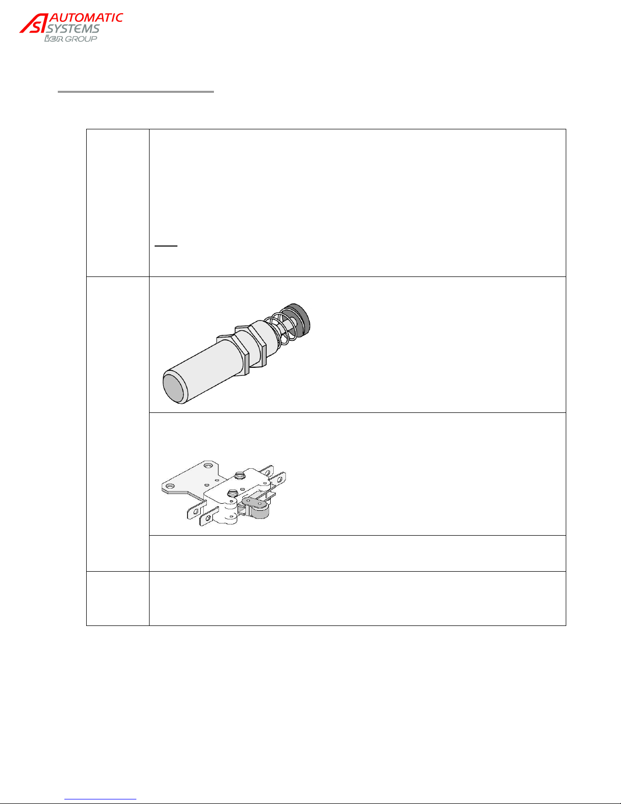
Clean the bodywork, walls and obstacles with water and a light detergent (nonchlorinated).
Clean the stainless steel mobile combs (optional) with a cleaning product designed for
stainless steel surfaces. Automatic Systems can provide a cleaning product approved
under reference 0/6031/000.
Repair any possible splinters, bumps or scratches on the painted surfaces of the
equipment.
Note: Maintenance frequency must be adapted to the conditions of use (especially, when
the turnstile is installed in an oxidizing environment: entrance of a public pool, seaside,
industrial plant, etc.).
1.000.000
cycles
Replace the shock absorber (N, ch.3.8. ), which softens with wear.
Replace the two limit switches (J, ch.3.8. ), as electric resistance increases with contact
wear.
Verify the tightening of the screwed elements of the mechanical structure and mobile
combs.
5 years
Replace the control board battery: lithium cell 3V/48mA. Automatic Systems can provide a
product approved under reference 0/7111/010.
To reach the battery, remove the front panel of the control board by unscrewing its 4 bolts.
4. MAINTENANCE
NAM-TRS372-MT-EN-C p34/38
The information in this document is the property of Automatic Systems and is confidential. The consignee withholds from using it for anything other than the use of the products or the execution of the
project to which they belong and withholds from communicating it to third parties without prior written agreement from Automatic Systems. Document subject to change without prior notice.
Page 35
Turnstile out of service.
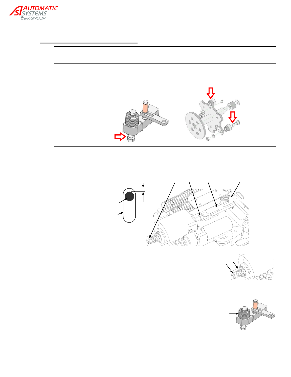
See messages on the control board display ("OPERATION" group, "Status"
parameter).
Friction is perceptible
during movements.
The bolts and/or rollers may be jammed, especially in harsh environments
(e.g., in a sea environment). Use a silicon spray on parts that need to be
released.
Obstacle cannot be
unlocked.
Leave 1 to 2 mm gap between the connecting rod (B) of the electromagnet
and the bolt stem (D) (setting the length of the connecting rod by means of
nuts P and Q) in order to create an impact with the bolt when the
electromagnet is activated.
The electromagnets may be blocked if tightened
too firmly. Slightly loosen nut (Q) in order to
decompress spring (C).
Spring (C) does not have the energy necessary to pull the bolt. Compress
the spring by tightening nut (Q) or replace it.
Obstacle cannot be
locked.
Bolt release spring (K) is loose. Retighten the
spring by adding a few turns to it.
P
B
D
1 to 2 mm
D
B
Q
Q
C
K
5. TROUBLESHOOTING
NAM-TRS372-MT-EN-C p35/38
The information in this document is the property of Automatic Systems and is confidential. The consignee withholds from using it for anything other than the use of the products or
the execution of the project to which they belong and withholds from communicating it to third parties without prior written agreement from Automatic Systems. Document subject to
change without prior notice.
Page 36
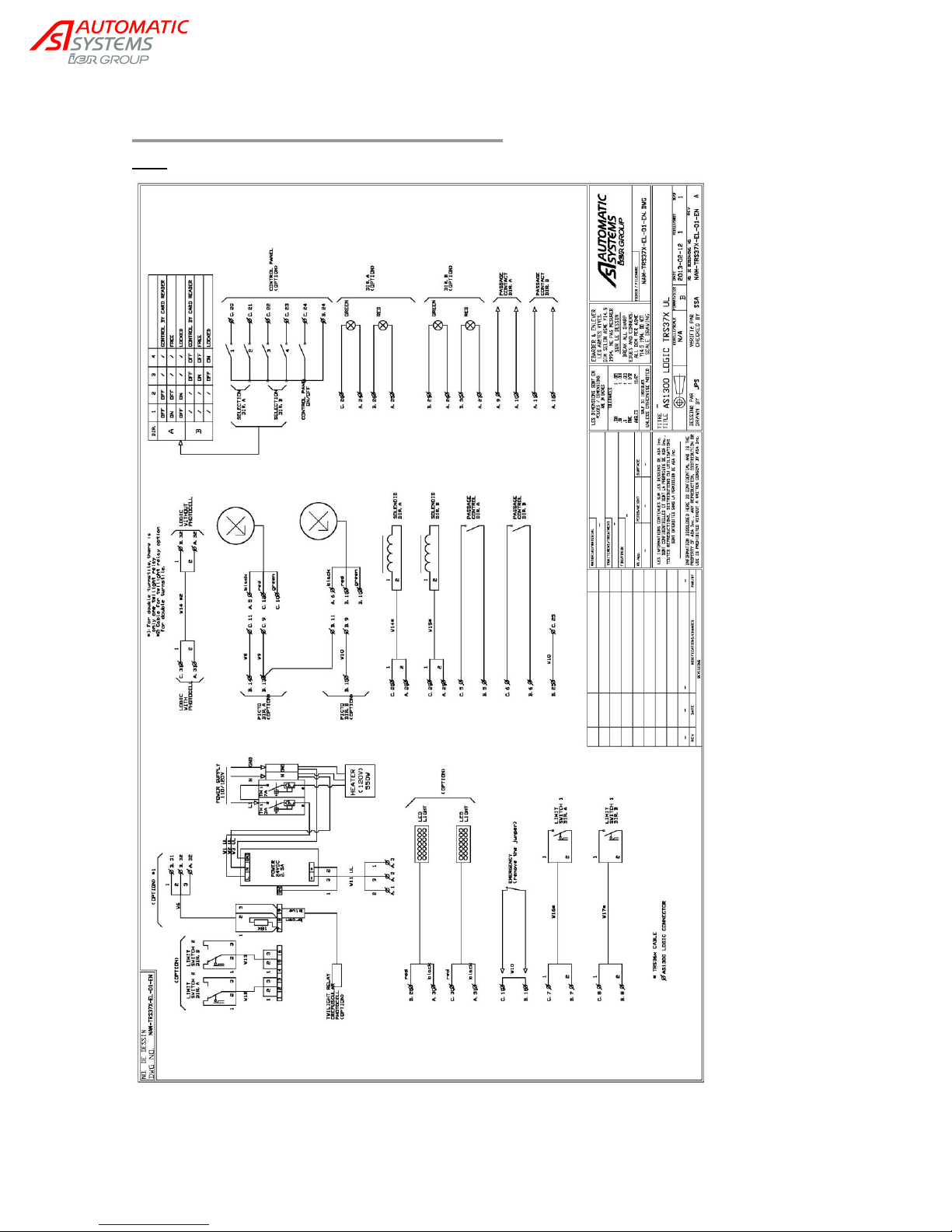
6. ELECTRICAL DIAGRAMS
Note: Informative diagram. Reference document is the one included with the equipment.
NAM-TRS372-MT-EN-C p36/38
The information in this document is the property of Automatic Systems and is confidential. The consignee withholds from using it for anything other than the use of the products or
the execution of the project to which they belong and withholds from communicating it to third parties without prior written agreement from Automatic Systems. Document subject to
change without prior notice.
Page 37
C
B
A
1
BCL1+
Not used
BLC3+
Not used
24V
PWR
2
BCL1-
Not used
BCL3-
Not used
0V
PWR
3
BLC2+
Not used
BCL4+
Not used
PE
4
BCL2-
Not used
BCL4-
Not used
(PE)
5 DI1
Pass Control A
24V GND
6
DI2
Pass Control B
24V GND
7
DI3
FCA (NO)
24V GND
8
DI4
FCB (NO)
24V GND
9 REL1+
Grn Ori Icon A
REL3+
Grn Ori Icon B
REL5+
Pass Contact A
10
REL1-
REL3-
REL5-
11
REL2+
Red Ori Icon A
REL4+
Red Ori Icon B
REL6+
Pass Contact B
12
REL2-
REL4-
REL6-
13
DI5
Alarm (NO)
(= Out of Service)
24V GND
14
DI6 24V GND
15
DI7 24V GND
16
DI8 DI18
GND
17
DI9 24V GND
18
DI10
Evacuation (NC)
24V GND
19
DI11
24V GND
20
DI12
Desk A1
24V GND
21
DI13
Desk A2
24V GND
22
DI14
Desk B1
24V GND
23
DI15
Desk B2
24V GND
24
DI16
Desk Key (NO)
24V GND
25
DI17
Connected to 24V
24V GND
26
DO7
Grn Fct Icon A
DO8
Red Fct Icon A
GND
27
DO9
Heater
24V GND
28
DO10
Solenoid A
DO13
LED Lighting
GND
29
DO11
Solenoid B
DO14
Grn Fct Icon B
GND
30
DO12
LED Lighting
DO15
Red Fct Icon B
GND
31
AO1
Used (=AI2)
(*)
AO2
Used
GND
32
AI1 AI2
Light sensor
GND
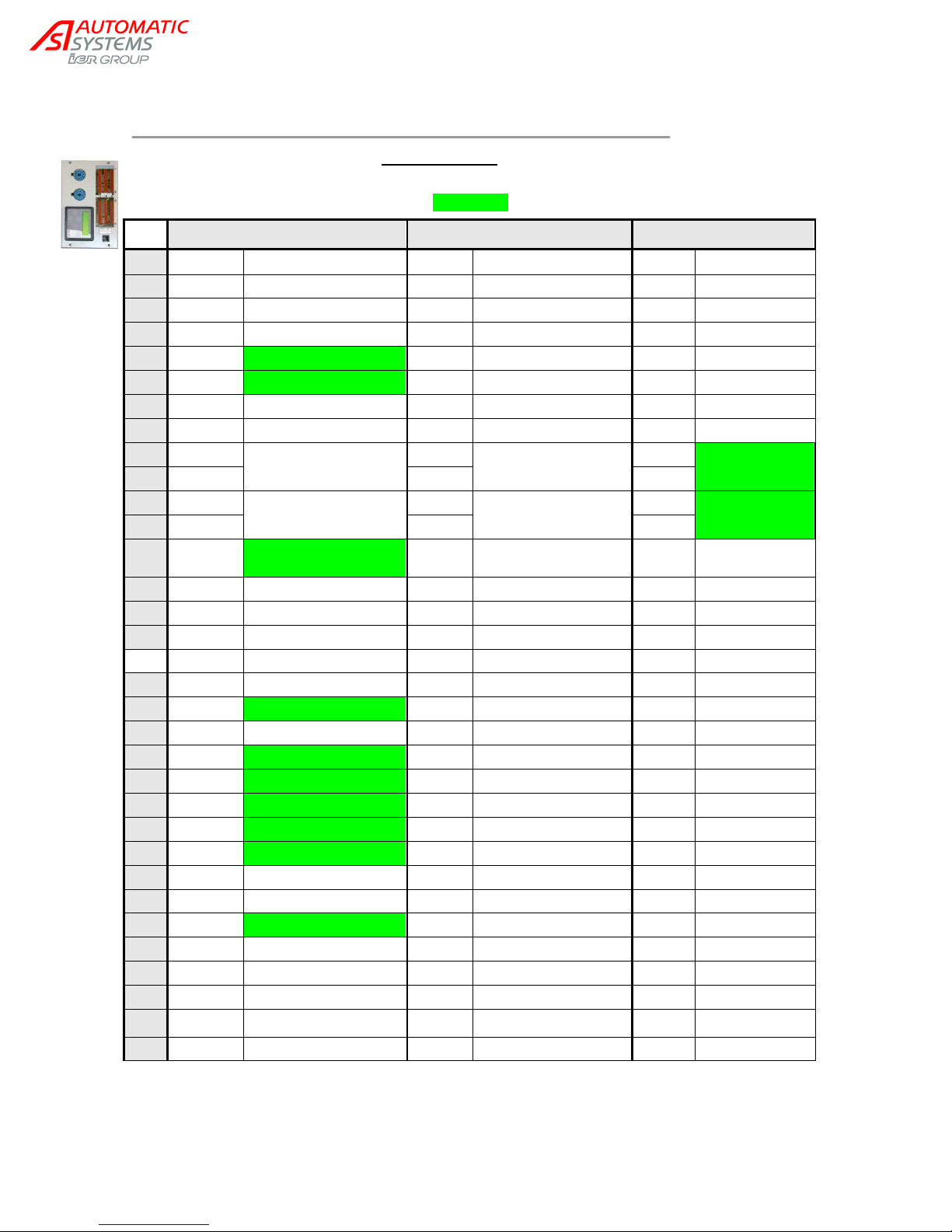
6.1. Control board terminal block assignment
The table below indicates the factory settings of the inputs/outputs.
The outputs can be set differently in the OUTPUT FUNCTIONS group.
The inputs/outputs of the options are highlighted.
(*)
Value of analogue input AI2 (light sensor signal) is copied to analogue input AO1 to be used in a double
turnstile. This signal can then be cabled to the second AS1300 in lieu of a second light sensor.
NAM-TRS372-MT-EN-C p37/38
The information in this document is the property of Automatic Systems and is confidential. The consignee withholds from using it for anything other than the use of the products or
the execution of the project to which they belong and withholds from communicating it to third parties without prior written agreement from Automatic Systems. Document subject to
change without prior notice.
Page 38

AUTOMATIC SYSTEMS BELGIUM - HQ
North America technical support
NAM-TRS372-MT-EN-C p38/38
The information in this document is the property of Automatic Systems and is confidential. The consignee withholds from using it for anything other than the use of the products or the execution of the
project to which they belong and withholds from communicating it to third parties without prior written agreement from Automatic Systems. Document subject to change without prior notice.
Automatic Systems
T: 1 800 263.6548 ext 233 - F: 450.659.0966 - C:514.239.7611
www.automatic-systems.com
 Loading...