

Page 1

SNACKSHOP Model 7000
SNACKSHOP Model 7000
SNACKSHOP Model 7000
SNACKSHOP Model 7000
SNACKSHOP Model 7000
instruction
manual
for
SNACKSHOP Model 7000
AUTOMATIC
-
PRODUCTS
internolionoL
ltd.
75 WEST PLATO
BOULEVARD'
ST.
PAUL,
MINNESOTA 55107-2095
Page 2

table
of
contents
Page
16
16
16
16
16
16
15
16
17
WARRANTY.
. . . . . . . . . . . . . . . . . . . . . . . . . . . . . . . . . . . . . . . . . . . . . . . . . . . . . . . . . . . . . . . . . . 1
SPECIFICATIONS.
. . . . . . . . . . . . . . . . . . . . . . . . . . . . . . . . . . . . . . . . . . . . . . . . . . . . . . . . . . . . . . 1
CAPACITIES. . . . . . . . . . . . . . . . . . . . . . . . . . . . . . . . . . . . . . . . . . . . . . . . . . . . . . . . . . . . . . . . .
..
2·3
UNPACKING.
. . . . . . . . . . . . . . . . . . . . . . . . . . . . . . . . . . . . . . . . . . . . . . . . . . . . . . . . . . . 4
INSTALLATION.
. . ....... . .... . . .......
..
. . . . . . . . . . . . . . . . . . . .
............... .
..
4·7
COMPONENTS. . . . . . . . . . . . . . . . . . . . . . . . . . . . . . . . . . . . . . . . . . . . . . . . . . . . . . . 8
1.
Power
Supply. . . . . . . . . . . . . . . . . . . . . . . . . . . . . . . . . . . . . . . . . . . . . . . . . . . . . . . . . . . . . 8
2.
Changer. . . . . . . . . . . . . . . . . . . . . . . . . . . . . . . . . . . . . . . . . . . . . . . . . . . . . . . . . . . . . . . . 8
3.
Mode Switches. . . . . . . . . . . . . . . . . . . . . . . . . . . . . . . . . . . . . . . . . . . . . . . . . . . . . . . . . . . . 8
4. Bill Validator . . . . . . . . . . . . . . . . . . . . . . . . . . . . . . . . . . . . . . . . . . . . . . . . . . . . . . . . . . . . . 8
5. Selection
Panel.
, _ _. . . . . . . . . . . . . . . . . . 9
6.
Vend
Motors.
. . . . . . . . . . . . . . . . . . . . . . . . . . . . . . . . . . . . . . . . . . . . . . . . . . . . . . 9
7.
Price
Setting Without
Using
M.I.5. 9-10
8.
Price
Checking Without
Using
M_I.S.. . . . . . . . . . . . . . . . . . . . . . . . . . 10
9.
Management Information System
M.I.5.
. . . . . . .
..
..._. . . . . . . . . . . . . . . . . . . . . . . . . .
..
11
10.
Price
Setting
Using
M.I.5.
and
Product Code. . . . . . . . . . . . . . . . . . . . . . . . . . . . . . .
..
11
11.
Price
Checking Using M.I.S _. . 11-12
12.
Cash
Accountability
.....
__
_. _. . . . . . . . . . . . . . . . . . . . . . . . . . . . . . . 12
13. Test Vend Mode Operation. . . . . . . . . . . . . . . . . . . . . . . _. . . . . . . . . . . . . . . . . . 12
14.
Machine Identification Number _ " _ _. . .
..
12
15.
Service Diagnostic Display
__
_ 12-13
16.
Lighting
System
. . . . . . . . . . . . ..._. . . . . . . . . . . . . . . . . . . . . . . . . . . . . . . . . . . . . 14
17.
Main Product
Shelves
_ _ _. . . . . . . . . . . . . . . . . . 14
18.
Delivery Bin. . . . _ 14-15
19.
Coin
Return. . . . . . . . . . . . . . . . . . . . . . . . . . . . . . . . . . . . . . . . . . . . . . . . . . . . . .
..
15
20.
Coin Acceptance. . . . . . . . . . . . . . . . . . . . . . . . . . . . . . .
15
21.
RemovalofGum
and
Mint
Motors and/or
Ejectors.
. . . . . . . . . . . . .
..
15
22.
RemovalofGum
and
Mint Shelf _. _
15
23.
RemovalofControl Panel. . . . . . . . . . . . . . . . . . . . . . . . . . . . . . . . . . . _
15
OPTIONAL EQUIPMENT
1. Ventilating Fan. . . . . . . . . . . . . . . . . . . . . . . . . . . .
2. Unification
Kits.
. . . . . .
..
. .
3.
Gum
and
Mint.
. . . . . . . . . . . . . . . . . . . . . . . . . . . . . . . . . . . . . . . . . .
4.
Special Spirals. . . . . . . . . . . . . . . . . . .
..
. .
5. Soup Dispenser. . . . . . . . . . . . . . . . . . . . . . . . . . . . . . . . . . .
6. Dollar Bill Validators .__. . _ .
CLEANING.
_. _. . . . . . . . . . . . . . . . . . . .
TROUBLESHOOTING .
BILL
VALIDATOR
MOUNTING INSTRUCTIONS
· .22-25
48
· 26-27
· 36-37
· .39-47
.
20-21
· 18-19
. . . . . . . . . . . . 38
38
· _28-35
PARTS LIST
,.
Cabinet. . . .
2. Connectors. . . . .
3. Control
Panel
.
4.
Delivery
Bin.
. . . .
..
. .
5.
Door-Front
Panels
and
Stylings .
6.
Door-Inside
Front
. .
7.
Door-Outside
Front
.
8.
Electrical
Harnesses
.
9. Main Interlock
Box
.
10. Product
Shelves-Snack~Candy-Gum
&
Mint
SCHEMATIC.._
ii
&49
Page 3

schematic
_
1-10
+
__
----'
..t...-
__
-L..
L-
__
....L
__
-----'
MAIN
PRODUCT
MOTORS
SHOWING
HARNESS
CONNECTIONS
B-I--_...J
A
G-h--_...J
CONTROL
BOARD
r---..,
I I
$1
BILL
VALloAToR
I I
L
-l
11
e<------+-12
13
e<------+-14
II
BLOWERIBALLAST
MOTOR
~--
L
__
J
"'"
OPTIONAL
EQUIPMEJIIT
INDICATED
'N
BROKEN
LINE
AREAS
SELECTION
SWITCH
PANEL
OPERATE
SWITCH
TYPICAL
MOTOR
CIRCUIT
SCHEMATIC
DIAGRAM
SNACKSHOP
600017000
AUTOMATIC
PRODUCTS
CO.
ST.
PAUL
MINNESOTA
55107
PART
NO.
460353
ii
Page 4

WARRANTY
.,
[I
The
Automatic
Products
Company
warrants
this
authorized
dealerordistributor
without
charge
to
~
vendor,
manufactured
by
it,tobe free from
defects
the
owner.
~
in materialorworkmanship
under
normal use.
Our
[I
obligation
under
this
warrantyisto
the
original
pur'
This
warranty
applies
onlytoour
products
which
[I
are used
within
the
United
StatesofAmerica,
and
is
chaser
only
andislimitedtomaking goodatour
factory
any
partorparts
thereof
which shall, within in lieuofall warranties expressedorimplied, includ-
two
(2) years
after
deliveryofsuch
producttothe
ing,
but
not
limitedtoimplied warrantiesofmer-
[I
original purchaser, be
returnedtousorto
our
author-
chantibilityorfitness for a particular
purpose,
and
ized dealer
or
distributor
from
whom
purchased with
no
representativeorpersonisauthorizedtoassume
[I
for us
any
other
liability in
connection
with
the
sale
all
transportation
charges prepaidtoour
factory,
and
which
our
examination
shall disclosetoour
of
our
products.
satisfactiontohave been defective. The
Automatic
Products
Company
reserves
the
~
righttomake
any
changesorimprovements
in its
~
This
warranty
does
not
extend:1:To
anyofour
products
without
notice
and
without
obligation,
and
~
products
which
have been subjected
to
misuse,
without
being requiredtomake
corresponding
changes
~
neglect,
accident,
incorrect
wiring,
improper
instal-
or
improvements in
products
theretofore
manufac-
~
lation,orto
use in violationofinstructions furnished
turedorsold.
~
R
by us; 2:Tounits
which have been repairedoraltered
[8
R
outsideofour
factory;3:To
'cases where
the
serial
numberofthe
product
has been removed, defaced
or
changed;4:To
electrical
components,
lamps,
tubes
or
~
circuit
breakers;5:To
accessories
notofour
own
~[I
~
manufacture
used
with
our
products.
Any
part
manu- AUTOMATIC PRODUCTS COMPANY
~
facturedbyAutomatic
Products
Company,
found
by
75
West Plato Boulevard
~
ustobe defective
within
the
warranty
period will be St. Paul, Minnesota
55107
~
~
exchangedbyAutomatic
Products
Companyortheir
~
~
.
Snackshop
7000
has
been
designed
from
superiorengineering and
with
quality
throughout.
It
has
been
built
of
rugged construction
for
many years
of
reliable trouble-free operation. Note:
(For
Indoor
use
only)
To
achieve
the
most economical trouble-free operation
from
your
Snackshop
7000,itis
recommended
that
this service manualbethoroughly
read and in-
structions
followed
pertainingtoall load ing and servicing, etc.,ofthe vendor.
Should
you
have questions pertainingtothis
manualorthe vendor, please
contact
your
local
Automatic
Products Company
distributororwrite
direct-
ly
to:
Service Manager
Automatic Products Company
75
West
Plato Boulevard
St. Paul, Minnesota 55107
SPECIFICATIONS
HEIGHT-72"
WIDTH -
38-7/8"
DEPTH -
35"
FLOOR SPACE REQUIRED - 9.5
SQ.
FT.
SHIPPING
CONTAINER
SIZE - 72.5 CU. FT.
POWER REQUIREMENTS - 115
V.,
60 HZ.
STANDBY
AMPERES - .7 OPERATING AMPERES - 3
..
Page 5

capacities
Unless otherwise specified machine willbeshipped with spiral
assortment
shown below.
Figures
in
circles represent capacitiesineach spiral.
2
G>
G G
E>
G
G
G e
e
e
e
e
e
ele
e e
e
G
e
e
49
49
e
e
MODEL
7525
Capacityasshown:
310
Units
G
G>
e
'9
'9
e
e
48
E)
ce
~,:
II':
,,:
at:
lit:
: : :
:
:
a,:
It:
,t:
at:
a,:
lit:
: : :
:
:
a,:
MODEL
7540
Capacityasshown:
677
Units
G>
~
G G G
G G
(f)
e
4!)
4!)
e e
e
e
4!)
4!) 4!)
\D
4!)
~
4!)
C)
C)
CD
C)
~
C)
CD
~
MODEL
7630
Capacityasshown:
370
Units
G
G>
4D>
G)
G
8
E)
ce
(E)
8
~
e ~ G
e
I I I I I
:.,:
1It:.t:
lit:
•
. .
8
e e
e
4!)
MODEL
7530
Capacityasshown:
437
units
G>
4D
e
4!)
E)
lit:
lit:
,t:
a,:
u:
lit:
II': II':
lor:
at:
~
~
~
~
lit:
II':
~,:
i':
~,:
a,:
II:
lit:
: :
: :
,
MODEL
7545
Capacityasshown:
775
Units
G G
G
G G
G
~
4!)
4D
e
CD
e e
4!)
e
e
4D
~
49
~
I I I I I
:.t:•t:.
t:
lit:
'
, ,
CD
'9
e
49
CD
MODEL
7635
Capacityasshown:
502
Units
MODEL
7535
Capacityasshown:
551
Units
MODEL
7550
Capacityasshown:
894
Units
MODEL
7640
Capacityasshown:
617
Units
..
Page 6

•
MODEL
7645
Capacityasshown:
731
Units
G>
G
e
e
e
e
e
e
e e
.t;
.t;
.t;
,t;
lit;
.1;
.t;
it;
III;
lit;
lit;
lit;
.t;
It;
lit;
.t;
It;
lit; lit; lit;
~
.t;
.t;
.t;
u;
lit;
I
,
MODEL
7650
Capacityasshown:
839
Units
capacities
G
e
e e e
.t;
.t;
lit;
;
;
;
;
; ;
;
lit;
III;
lit;
,t;
.t;
lit;
.t;
it;
lit;
lit;
lit;
lit;
.t;
.t;
It;
It;
It;
lit;
It;
lit;
-
-
lit;
lit;
.t;
,t;
lit;
it;
-
-
MODEL
7655
Capacityasshown:
955
Units
iii.: Ii':
it:
Ii.: Ii.: II': Ii.:
at:
Ii.:
ill:
I':
Ii.:
Ii.:
II':
.t:
Ii': : :
: II': II':
I':
II':
lit:
;
lit; lit;
It:
;
n;
MODEL
7660
Capacityasshown:
1062
Units
PRODUCT SIZE CAPABILITY
WIDTH WIDTH
DEPTH
OF
DEPTH
OF
of
Snack
ShelvesofCandy
Shelves
Snack
Spirals
Only
Candy
Spirals
Only
SHELVES
HEIGHT
Only
Only
Choice:
Choice:
Top
7-3/4"
2Y>"to5Y.."
1"
to
2Y.."
12 - Item Spiral
1-7/8"
Second
7-1/4"
2Y>"to5Y.."
1"
to
2Y.."
7 - Item Spiral
2-1/2"
15 - Item Spiral
1-5/16"
Third
6-5/8"
2Y>"to5Y.."
1"
to
2Y.."
10 - Item Spiral
2-1/16"
18 - Item Spiral
1-1/16"
Fourth
7-1/4"
2Y,'to5Y.."
1"
to
2Y.."
12 - Item Spiral
1-11/16"
24 - Item Spiral
3/4"
Fifth
6-3/4"
2Y,'to5Y.."
1"
to
2Y.."
15 - Item Spiral
1-5/16"
30 -
Item
Spiral
1/2"
Sixth
6-1/4"
2Y,'to5Y.."
1"
to
2Y.."
Ten selection shelves
for
candy and
other
narrow
items
fit
on allsix positions.
Spiral
of
one item capacity can be freely interchanged
with
any otherofthe
same
diameter.
Boxed items
may
need
slightly
larger clearancestovend
properly.
Movable spacers availabletoadjust
widthstoranges shownineach selection.
Gum-and-Mint
Capacity.
Itisdifficulttodetermine the true capacity duetovariationsofproduct
size.
The
average
capacity
for
the Gum-and-Mint Shelfis170
items.
3
Page 7

unpacking
_
The Snackshop 7000isassembled and packedsothat
a mini-
mum
amountoftimeisnecessary
for
preparation to install
it
on location. The
following
steps
are
recommended to insure
correct unpacking.
1. Shipping Damage:
Thoroughly
inspect the
exteriorofthe
carton
for
damage which may
have
occurred during ship-
ment. Report any damage
to
delivering carrier and
follow
their
instructions.
2.
Remove staples
from
lower
edge
and those at topofcar-
ton,
and slit carton verticallyatthe taped corner. Open
and remove carton. Remove-the remainder
of
the packing
material. On machines shipped
with
lockinplace, the
keys
are
stapled to the carton
base.
3. Remove Vendor With A
Fork
Lift
Truck:
Remove the car-
ton
from
the vendor. Open the
door
on the vendor and
remove the hold down bracket at the
front
centerofthe
cabinet
base
and
close the vendor door. From the
front
of
the vendor
tip
the vendor backward and run forks under
the cabinet.
4. Removing Vendor
WithoutAFork
Lift
Truck:
Remove
the carton
from
the vendor. Remove
v..
" piece
of
plywood
installation
1.
GENERAL:
In
some
locations, duetothe
sizeofthis
machine
itisnot
possibletomove the
fully
assembled
machine through doors
or
narrow hallways. For
such
locations the doorofthis vendor
canberemoved, thus
reducing the clearance required down to
32
inches. For
narrower doors the sliding panel
canbepushed back in·
side the cabinet by removing the control stop (Item
#23
Page
24).
DOOR REMOVAL:
To
remove the door, swing door
to
90
degrees.
Remove bolt and washer on door end
of
door
stop.
Disconnect light harness. The upper hingeissecured to the
cabinet
by
one bolt extending through the hinge from the
in-
sideofthe cabinet. Use a 1/2 socket to remove. Pull the door
forward, the upper hinge will slide out of the top guide, free-
ing the door. Lift the door up and out of the lower hinge.
Remove left sidepanel extension which
is
held byfourscrews.
Remove the cabinet to door filler assembly which
is
held
in
by
twelve
screws.Toinstall the door, reverse the
above
procedure.
2.
LEVELING
THE
MACHINE
on locationisimportant
for
the proper
function
of
the machine. The
four
leveling
screws in the
legs
are
the meansofleveling the machine.
After
positioning the machine, level machine in
front
to
rear
and
right to
left
directions.
After
leveling, turn
front
right (lock side) leveling screw in about one-half
turn
to
drop this corner slightly to make the
door
easiertoclose
and lock.
3.
THE
MAIN
POWER CORDisshipped
fully
inside the
machine. Extend
it
through the hole located in the
base
on the
left
(hinge side)ofthe machine behind the trans-
former. Install the plate
with
key hole slots over the
two
screws in the
base
by the cord hole
and
drive screws
tight
to hold cord in place. Plug the 3 pin grounded plug
into
a
properly grounded
115V60HZ
outlet
only.
In order to comply
with
electrical safety regulations
and
Underwriters Laboratories requirements, all electrical
4
located just
beh
ind the
front
legs,
then open the door on
the vendor
and
remove the hold down bracket at the
front
centerofthe cabinet
base
and close vendor door. From
the
frontofthe vendor
tip
the vendor back far enough
to
clear the wood strip across the
frontofthe
base.
Slide
vendor toward the back
until
the back
legs
are
off
the
base
and
pull
base
out.
NOTE:
Because
the weight concentration is toward the
back
of
the cabinet,
trucking
and
lifting
should be done
from
the back.
CAUTION
shouldbetaken when
trucking
from
side.
5.
On machines
with
lock in place, unlock,
and
turn
handle
to
open door.
When
no lockisfurnished, remove tape
and
turn handle. Swing doortoits full open position.
6.
Remove all packing tape
and
paper
from
various
areas
of
machine
and
the shipping strap.
7.
Warranty: The warranty cardisattachedtothe cover
of
this manual.Itmustbefilled
outinfull
and mailed
at
once to insure coverage.
8.
IMPORTANT: Aset of anchoring brackets aresent with
each machine. Thekitislocated
in
thebottom ofthe machine
complete with instructions. It isrecommended thatthis kit
be
installed toprevent shifting ofthe machine.
equipment mustbeproperly polarized and grounded. The
Snackshop 7000
is
wiredsothatitis
properly polarized
in accordance with the electrical code.
If
the wall
outlet
is
wired
and
grounded properly, then the vendor will con-
nect properly.
Shown in
View
A & B
are
two
properly grounded
and
polarized wall outlets. Oneisa three wire grounding type
wall
outlet
(see
View A) and oneisa
two
wire wall
outlet
(see
ViewB)withanadapter in place.Tomake a polarity
check
use
a 115
volt
neon test lampasshownora
volt
ohm meter. The
hot
sideofthe
circuit
should always
be
counterclockwise from the ground terminal (which should
be
at the
bottom).
Should the
polarity
at the wall
outlet
show any way other
than that shown below, the
outlet
shouldberewired.
Using a voltmeter, perform
the
following checks from the
illustration below.
A.C.HOT
(B)
(A)
I
I (B)
(Al to (B)
=117VAC (+-10%)
A.C.NEUT
(A)
(A) to (C)
=Less than 1
VAC
EARTH
(C)
- (C)
(B) to (C) =117VAC (+-10%)
GROUND
NOTE: Should the readings be different from above,
have a certified electrician correct the problem.
Page 8

•
installation
.....------
G D
Figure
3.
REMOVING
AND
INSTALLING
SPIRAL.
REMOVAL
OF
SPI
RAL:
Grasp
the
frontofthe
spiral
and
turnitclockwise.
Lift
the
spiralupand
offofthe
spiral
lock.
When replacing a spiral
attachitaround
the
tabonthe
spiral lock and
turn
the
spiral
counterclock-
wisetolockitin
place.
Be
sure
the
front
endofthe
spiralispositioned
properly
(with
the
front
endofthe
spiral
pointing
downward
on
the
left side) (see Figure 3).
The
spiral lockisattached
between
the
spiral
retainer
tabs. Give a light
forward
pull
on
frontofthe
spiral
to
check
if itislockedinplace.
5.
BtL
J-
4.
LOADING
SNACK
SHELVES:
Open
doortofull
open
position,
push
downonwhite
plastic lock lever (Figure 1)
on
right
side panelbyshelftounlock
shelf,
holding
lever
down.
Grasp
the
shelf
slightly
and
pull
forward
until shelf
reaches its
stop.
The
shelves
tilt
down
(do
not
drop)
to
make
loading
easier.
Only
one
product
shelf
shouldbein
the
loading
positionata
time.
When
returning
a shelf, be
sure
the
shelfisin
its full
homeorvend
position.
Begin
loading
with
the
top
shelf. Moveitto
the
loading
position.
The
height
spacing
for
itemsisgreatestinthis
shelf
and
the
tallest
bagged items
should
be placed
there.
Soft
items,
suchaspastry,
pies,
etc.,
should
be placedinthe
lowest
snack
shelf,
making
the
drop
distanceasshort
as possible.
IMPORTANT:
Product
must
notbeforced
into
the
spiral
spaces
but
should
fit freely. If
the
productistoo
tight,
use
a larger
pitch
spiral.
The
bottomofthe
product
should
be
placed
on
topofthe
spiral wire
that
restsonthe
shelf
sur-
face (see Figure 2).
The
widthofthe
product
must
be
greater
than
the
diameterofthe
snack
spiral. If itissmall-
er,
the
product
may
fall
through
whenitisinthe
front,
readytovend
position.
Figure
1.
MOVING
SHELF
TO
LOADING
POSITION.
Figure
2.
PLACEMENTOFPRODUCT
ON
MAIN
PRODUCT
SNACK
SHELVES
AND
FRONT
END
POSITIONOFSPIRAL.
Figure
4.
ALIGNMENT
OF
MOVEABLE
PRODUCT
SPACERS.
5
Page 9

installation
6.
PRODUCT
SPACERS-5
SELECTION
SHELF:Aprod-
uct
spacerisusedtoreduce
the
widthofthe
product
area
and
shouldbeusedonany
5-selection
snack
shelf
where
the
product
widthis4%,'orless. Spacers
should
fit
within
1/8"ofthe
product
but
should
not
fit
tight
against
the
product.
There
are
three
positionsineach
snack
space
where
these
spacers
canbeplaced .Toinstall
the
spacer,
align
the
lock
ears
(on
the
lower
edgeofthe
spacer) with
oneofthe
three
setsofslots (one
front
and
one
rear).
(See Figure
4).
Push
the
spacertothe
reartoallow
the
earstoenter
the
slots,
then
allow
the
spacertomove for-
ward.
Be
sure
the
ears
areinthe
same
setofslots,
front
and rear. (See Figure
4).
Continue
loading
all
spirals
adjust
with spacers
where
neededinthe
top
shelf.
Return
the
top
shelftothe
vend
position
and
following
this
proce-
dure
load
the
remainderofthe
large spiral shelves.
The
shelf
divider
separating
the
right (lock side)
column
from
the
next
columnismovabletoallow vendingofproducts
wider
than
5Yz"
in
the
second
column.
If thisisused
the
right
column
must
be usedtovend a
narrower
product.
7.
LOADING
MAIN
PRODUCT
CANDY
SHELVES:
The
1Q-selection
(candy
type)
shelves
are
loaded similartothe
5-selection shelves
except
that
the
bottomofthe
product
sitsonthe
shelfinfrontofthe
spiral wire (see Figure 5)
that
restsonthe
shelf.
These
products
must
also fit
prop-
erlyinthe
spiral space;donot
force
product
into
spiral.
6
DETAIL
A~
Figure
5.
PLACEMENTOFPRODUCTONMAIN
PRODUCT
CANDY
SHELVES
AND
FRONT
END
POSITIONOFSPIRAL.
These
spirals
are
removed
and
installed
the
same as
the
large spiral (see Figure 3),
except
that
the
front
end
posi-
tionisdifferent
(approximately5o'clock)
(see Figure 5)
and
the
front
left sideofthe
spiral
mustbebehind
the
small
tab
locatedonthe
left sideofthe
product
space side
wall (see Figure
5,
Detail A).
8.
PRODUCT
SPACERS-10SELECTION
SHELF:
The
10-
selection
shelves are
equipped
withaproduct
spacer
(see
Figure 6)
that
canbepivoted
from
the
right sideofeach
product
space.
These
spacers
should
be pivoted
out
to
hold
the
product
upright,
but
not
tight
against
the
prod-
uct.
Leave
about
1/8"
clearance
between
the
spacer
and
the
product.
Figure
6.
10
SELECTION
SHELF
PRODUCT
SPACER
POSITIONEDTOHOLD
CANDY
UPRIGHT.
9.
PRODUCT
PUSHER:
The
machine
'contains
enough
pushers
for
youtoinstall a
pusheroneach
candy
spiral.
This
plastic
partisdesignedtopush
the
topofthe
prod-
uct
forward
while itisvending,
helping
it fall
from
the
shelf. It can also be usedwith
prod
ucts
that
have th e
wrapper
end
flaponthe
outsideofthe
package. In this
case,
the
pusher
prevents
these
products
from
hanging
on
the
spiralbyspreading
the
flap.
The
pusherisinstalled
approximately
210
degrees
from
the
front
endofthe
spiral
with
the tab
extending
forward
(see Figure 7). Lo-
cate
the
pusher
in its
proper
position,
hold it against
the
spiral wire
and
push
the
semi-circular
part
around
the
spiral wire.
Note:
Not
every
selection
spiral will need a
product
pusher.
(Example-Box
Items)
Page 10

J
:
..
J./
I~
If"-I
~~~=----~~==~
II:.
I I
I
d
Figure
7.
LOCATIONOFPRODUCT
PUSHER
ON
SPIRAL.
10.
BAGGED
OR
BOXED
ITEMSinthe
10-selection
shelves
if
not
loaded
properly
could
be a
problem.
The
sealed
edge
of
the
bag
may
get
under
the
spiral wire causing
the
producttohangupafterithas
been
vended.Itis
recom-
mended
that
the
lower
edgeofthese
typesofproduct
be
folded
forward
andup(see Figure 8)
nexttothe
product
before
inserting
into
the
spiral space. Itisalso recom-
mendedtouse an18count
spiral
for
bagged items
because
of
the
product
settlingtothe
bottomofthe
package.
11.
CIGARETTE
VENDING
FROM
SNACKSHOP
7000:
Cigarettes
canbevended
from
the
candy
shelves using
the
(15
capacity)
spiral
for
the
soft
pack
regular, king,
100mm
or
120mm
packs.
The
(12
capacity)
spiral
shouldbeused
for
(box)
packs.
12.
LOCK
PRODUCT
SHELVES.
After
all
the
product
has
been
loadedbesure
all shelves are
returnedtotheir
vend
position
behind
the
front
roller
guide.
13.
INSTALL
PROPER
PRICE
TABS
into
price
tab
holder
for
each
selectioninthe
main
product
area. (See Figure
9.)
14.
LOADING
GUM AND MINT.
The
Gum
and
Mint
shelf
is
located
below
the
Snack
Shelves
(optional).
Unlatch
the
shelfbypull ing
forward
the
two
metal
latches
located
to
the
right
and
leftofthe
shelf
and
pull
forward.
The
cover
canbepushed
backtothe
rear
for
easy loading.
The
shelf
contains
five individual selections.
The
first
selectiononthe
left
contains
two
fillers
for
use
with
thin
mints.
(Rolaids-certs,
etc.).
These
fillers can be
removed
for
standard
gumormints.
installation
F~ure8.
FOLDBAGGEDITEMSBOTTOM
EDGE
FORWARD
AND
UP.
Figure
9.
INSTALLING
PRICE
TABS.
The
two
selectionsonthe
rightofthe.
Gum
and
Mint
shelf
also have fillers.
These
selections
canbeused
for
standard
size gum and
mintsorthe
fillers
mayberemoved
for
larger
gum
and
mint
products.
Each
selection
has a display hinge
assembly
which
should
be
adjusted
after
the
shelfisloaded.Toadjust
the
display
hinge, loosen
the
wing
nut
and
slide
the
spring
hinge
of
the
flipper
over
the
second
product
and
fasten
tightly.
7
Page 11

components
INTRODUCTION
The
Snackshop
7000
represents
a new
conceptinvending.
There
arenopricing
switches,
vend
relaysorindividual
selection
switches.
Allofthe
machine
functions
are managed by a
con-
trol
board
located
on
theslid
ing panel.
The
control
board
operates
much
like a
computer.
In
additiontocontrolling
normal
machine
functions
the
control
board
has a
memory
and
micro
processor
for
the
incorporationofan M.I.5. (Man-
agement
Information
System),
M.I.5. was designedtogive
the
operator
an
accurate
and
up-to:date
viewofproduct
move-
ment
through
the
machine
(product
inventories, cash inven-
tories, service
time,
etc.).
Although
M.I.S.isan
invaluable
tool
for
the
operator,itis
not
necessary
for
normal
machine
opera-
tion.
The
following
instructions
deal with
the
functioning
and
setupoperationsofthe
machine
with
and
without
the
use
of
M.I.S. Read
the
instructions
from
beginningtoendtoget
a
complete
understanding
of
all
machine
functions
and
the
interrelationshipofcomponents.
1. POWER
SUPPLY
The
115
VAC
power
cord
from
the
wall
outlet
comes
into
the
machine
and
plugs
into
the
left
sideofthe
main inter-
lock
box
locatedonthe
bottom
hinge sideofthe
mach
ine.
The
other
four
connectionsonthe
interlock
box
are
for
the
transformer,
lights, fan
(optional)
and
power
plug
to
the
control
board.
All
these
connections
are
different
so
you
cannot
plug
theminwrong.
The
115
VAC
cord
goes
to
the
toggle
switch
inside
the
box
and
thentothe
cir-
cuit
breaker.
The
115
VAC
goestothe
transformer
which
supplies
two
output
voltages28VAC (11 & 12)
and
12.6
VAC (13 &
14).
These
voltages
then
pass
through
their
circuit
breakers
and
all
three
voltages goupto
the
control
board.
The
115
VAC (15 &
16)
goestothe
power
board
to
the
leftofthe
main
control
board.
The28VAC
and
12.6
VAC goestothe
top
left
plugonthe
main
control
board.
The
voltage usedonthe
vend
motorsis24
VDC. Do
not
test
them
with
AC voltage
and
be sure
polarityiscorrect
or
damage
will result.
When
removing
any
component
be sure
the
powerisoff.
Take
special
care
when
removing
the
control
board.
Do
not
lay
the
boardona metal surface.
2.
CHANGER
The
Snackshop
7000
can use
either
a Mars
(Me-SOOO)
or
(TRC-6000)
or
Coinco
(C300E 9234)or(9300l) changer. The
changeristobemountedonthe
changer
mounting bracket
located
on
the
sliding panel. Remove
the
changer
hold
down
screw
which
has
been
installedinthis bracket for shipment.
Hang
the
changeronthe
shoulder
studs provided. Re-install
the
hold
down
screw to lock
the
changerinplace. After secur-
ing
the
changertothe
changer
mounting
bracket, plug the
changer
into
one
of the two receptacles located below the con-
trol
board.
The
changer
plug will
determine
which
receptacle
should
be
used.Besure the
changer
cordisclear of
the
coin
return lever operation. Load
change
into
the
payout
tubes
and
turn
the
power switch on.
3.
MODE
SWITCHES
The
mode
switches
are
locatedonthe
control
board.
They
allow
for
controlofthe
following
machine
functions:
Set
price
mode,
check
price
mode,
test
vend
mode,
service
mode
and
set
serial
number
mode
(see Figure 10).
The
8
operate
mode
switchislocatedbyitselfonthe
front
face
of
the
sliding panel
above
the
selection
panel.
IMPORTANT:
When
operating
the
machineinany
mode
other
than
the
operate
mode,
the
door
mustbeopen.
The
machineisautomatically
putinthe
operate
mode
when
ever
the
doorisclosed.
NOTE:
Before closing
the
door
push
the
operate
button
to
home
any
motors
which
maybeoutofposition.
A.
Operate
Mode-Normal
machine
operation
featuring
total
control
of
coin mechanism
operation
and
accountabil
ity.
B.
Set
Price
Mode-Usedtoprogram
each
selection
with
a price
and/or
product
code.
C.
Check
Price
Mode-Usedtocheck
prices
and/or
prod-
uct
codesofprogrammed
selections.
D.
Test
Vend
Mode-Allows
normal
machine
operation
asinthe
operate
mode
except
management
data
is
recorded
separately
from
data
recordedinthe
operate
mode.
E. Service
Mode-Indicates
the
operational
condition
of
all
L.E.D. displays
and
vend
motors.
F.
Product
Data
Number
Mode-Machine
identification
number
for
M.I.S.
accountability.
4.
BILL
VALIDATOR
MODE
SWITCH
The switch located just below the
"product
data
mode"
switchisfor
use with a
dollar
bill
acceptor.
This
dual
switch has an on
and
off
position
for
both
price lines.
Price line
ttl
in
the
off
position
will
acceptadollar
bill
and
if a
selectionismade
will
pay
back
the
difference
in
change. If
for
some
reason
the
coin
return
leverispressed
instead
of
makingaselection
the
customer
will receive
back
that
individual dollar.
NOTE:
To
use
the
machine
as a
dollar
bill
changer
at
least
one
selectioninthe
machine
shouldbeset
for
over
$1.00.
Example
setA6for
a vend priceof$1.10.
There-
fore, if
your
machineisused as a
dollar
bill
changer
price
line
ttl
shouldbesettothe
off
position.
When a
dollar
is
accepted
and
the
coin
return
leverispushed
it will
pay
backadollar
in change. Price line
ttl
in
theonposition
will
acceptadollar
bill
andifthe
coin
returnispushed
pay
back
that
individual
dollar.
Price tt2 in
the
off
position
will
acceptadollar
bill
and
if
a
selectionismade
pay
back
the
differenceinchange.
In
the
on
position
(shoppers
mode)
afteradollar
bill
or
changeisinserted
will register
that
amountonthe
digital
display.
When a
selectionismade
the
amountonthe
digi-
tal display will
deduct
the
priceofthat
selection.Atthis
time
the
total
cash willbedisplayedofthe
amount
left
of
that
dollarsothat
another
selection
maybemade
without
inserting
more
money.
You,
therefore,
can
push
the
coin
returnfor
your
changeormakeasmany
selections
you
wanttountil
the
digital display reads
below
the
lowest
selling priceinthe
machine,
then
the
restofthe
money
will be paid
back
automatically.
NOTE:
When using
the
shoppers
mode,
thereisalso a
delay
time
incorporatedonthe
control
board.
If a
custo-
mer
does
not
make
another
selection
afteraperiod
of
10-15
seconds
the
changer
will pay
back
automatically.
Page 12

components
Figure 10. MODE SWITCHES.
USE
NICKELS,
DIMES,
QUARTERS,
DOLLARS
RECEIVE
CHANGE
BELOW
AMOUNT
OEPOSITED
Y
<J
CHECK
SELECTION
PRICE
MAKE
ANOTHER
SELECTION
USE
CORRECT
CHANGE
~
C
PUSH
0
FOR
I
COIN
N
RETURN
S
g
-
080
G0G
G0G
ion
~G
ns
0
00G
0
G
G
0GG
I
I
Figure 11. SELECTION PANEL
price
will
light and the display located on the selec-
tion panel
willbeblank. Any selection programmed
at
this reading
willberemoved from the operating
program. This would
be
used when shelves are moved
or
the
numberofselections changed to remove those
selections not present
in
the machine from the
program.
Castin
Displa
Glass
Select
Butto
o
ON
Mode Switches
o
CHECK
Mode Indicator L.E.D.'s
Mars
Changer
Payout Switches
o 0
TEST
SET
000
SERVICE
VEND
PRICE
o
IOc
7.
PRICE SETTING WITHOUT USING M.I.S.
Pricing
is
done through the selection panelinconjunction
with the mode switches.
A.
Press the mode switch "set price"
button
on the
control board (Figure 10). The L.E.D. above the set
6.
VEND MOTORS
The Snackshop 7000 incorporates the
useofa high
RPM
DC
Motor. The newDCMotor hasan85%
greater starting
torque over the Snackshop
400/500ACMotor,
yet
weighs
only 40%
of
theACMotors weight. Due to the new design,
the vend motor may no longer
be
homed
by
hand.
DO
NOT
TRY
TO TURN THE SPIRALSBYHAND.
DAM-
AGE TO THE MOTOR WILL RESULT. Any necessary
homing will
be
done by the machine. Itisalso important
to check polarity before applying current to the motor.
Two diodes and a capacitor are used to
pr~vent
circuit
feedback and may have to
be
checked when trouble
shooting
motor
problems.
5.
SELECTION PANEL
The selection panel (Figure 11) on the Snackshop 7000
incorporates the useofa self enclosed membrane switch
panel. This eliminates the need for individual switches and
wiring. The membrane switch panel
is
housedina stainless
steel panel with individual
buttons
protecting the switch
face. The casting
front
also houses the instruction and
digital display glass (Figure 12). Included on the instruc-
tion glass are three messages for customer instruction
when the machine can not complete a vend for
an
item
selected (Figure 12).
If
this condition occurs,anaudible
signal
is
given to the customer andanL.E.D. next to the
proper instruction
will
flash
until the customer takes
further action.
9
Page 13

components
r------
Customer Indicator L.E.D.'s
USE NICKELS, DIMES,
QUARTERS
RECEIVE CHANGE BELOW
CHECK SELECTION
PRICE
MAKE ANOTHER SELECTION
USE
CORRECT CHANGE
AMOUNT
DEPOSITED
<J
Figure 12. INSTRUCTION
AND
DIGITAL
DISPLAY GLASS.
USE NICKELS, DIMES,
QUARTERS
RECEIVE CHANGE BELOW
CHECK SELECTION
PRICE
MAKE
ANOTHER SELECTION
USE
CORRECT CHANGE
AMOUNT
DEPOSITED
/-11-1
<J
1_11_1
Figure 13.
10
B.
Press
button11on the selection panel and the display
will
show "00.00" (Figure 14) along with three audi-
ble beeps
willbeheard. Thisisthe price display and
can
be
incremented up by pressing button11and
down by pressing
button
12. Increments are
54
and
each increase
will
produce one audible beep.
CAUTION: Any selection programmed at
"00.00"
will
free vend.
C.
With the selling price displayed, press first the letter,
then the number for each selection to
be
sold at
that
price. Increment to your next price and enter those
selections. Repeat until
all
selections have been pro-
grammed with their proper price and product code.
8. PRICE CHECKING WITHOUT USING M.I.S.
After
all
prices have been programmed, they should
be
checked to verify
that
each selection has been programmed
correctly.
USE NICKELS, DIMES,
QUARTERS
RECEIVE CHANGE BELOW
CHECK
SELECTION
PRICE
MAKE ANOTHER SELECTION
USE
CORRECT CHANGE
AMOUNT
DEPOSITED
1-/1-11-11-'
I_I
I_I.
LI
I_I
<J
Figure 14.
A. Press the mode switch "check price" button on the
control board (Figure
10). The' L.E.D. above the
check price
button
will
light and the selection panel
display
willbeblank.
B.
Press the letter and then the number for the first
selection to be checked. The price display
will
show
the price
that
selectionisprogrammed for (Figure
15). Check the displayed price against the price tab
on the shelf for
that
selection.
C.
Continue to check prices until
all
selections
have
been checked. Follow "Price Setting Without
Using
M.I.5."
instructions to correct any errors found.
Page 14

USE NICKELS, DIMES,
QUARTERS
RECEIVE CHANGE BELOW
CHECK SELECTION
PRICE
MAKE
ANOTHER SELECTION
USE
CORRECT CHANGE
AMOUNT
DEPOSITED
1-11-1111-
- -
1_11_1.
I
_I
<J
Figure 15. SHOWING A SELECTION
PROGRAMMED FOR 45¢
9. MANAGEMENT INFORMATION SYSTEM (M.I.S.)
The Snackshop 7000
is
equipped with the data collect-
ing capabilities and the hardware to function
as
part
of
the Management Information System.
When
you are using
the M.I.S., the price setting and price checking require the
use
of
a product code.This
gives the operator the versa-
tility to use the
product
codesinany way to best fit
his
operation.
A
product
codeisa number (00 through 69), used to
identify a specific product or group
of
products. The
product
code need onlybeused when M.I.S.isbeing
used. The
product
code gives the operator total control
of
individual
product
salesorproduct
group sales.
The M.I.5. records by
product
code, the numberofvends
and total dollar
amount
vended for each product code
programmed. This gives the operator the versatility to
program a
product
code for each selectioninthe machine
or
one
product
code for
all
selections within the machine.
10. PRICE SETTING USING M.I.S.
AND
PRODUCT CODE
Pricing
is
done through the selection panelinconjunction
with the mode switches.
A.
Press the mode switch
"set
price"
button
on the con-
trol board (Figure 10). The L.E.D. above the set price
button
will
light and the display located on the selec-
tion panel
willbeblank. Any selection programmed
now
will
be
removed from the operating program.
Th
is
wouldbedone when shelves are moved or the
number
of
selections change (Example: Replacing a
five selection shelf for a ten selection shelf.).
components
USE NICKELS, DIMES,
QUARTERS
RECEIVE CHANGE BELOW
CHECK
SELECTION PRICE
MAKE ANOTHER SELECTION
USE
CORRECT CHANGE
AMOUNT
DEPOSITED
1-11-1
-II-
I_I
1_1.1=
=1
'-II-I
<J
1_11_1
Figure 16.
Press button 13 and a two digit display
"00"
will
appear on the selection panel whichisthe product
code, (Figure 13). Pressing
button
13 the display
will
changebyincrementsofone, going up.Bypressing
button
14 the increments
will
come downbyone.
B.
Press
button11on the selection panel and the display
will
show
"00.00"
(Figure 17) along with three audi-
ble beeps
willbeheard. Thisisthe price display and
can
be
incremented up by pressing
button11and
down by pressing button 12. Increments are
5¢
and
each increase
will
produce one audible beep.
CAUTION: Any selection programmed at
"00.00"
will
free vend.
C.
With the product code and selling price displayed,
press first the letter, then the number for each selec-
tion to
be
sold at that price and product code.
Increment to your next price
and/or
product code
and enter those selections. Repeat until
all
selections
have been programmed with their proper price and
product code.
11. PRICE CHECKING USING M.I.S.
After
all
prices
and/or
product codes have been program-
med, they should
be
checked to insure
that
each selection
has been programmed correctly.
A.
Press the mode switch "check price"
button
on the
control board (Figure 10). The L.E.D. above the
check price button
will
light and the selection panel
display
willbeblank.
11
Page 15

components
USE NICKELS, DIMES,
QUARTERS
RECEIVE CHANGE BELOW
CHECK
SELECTION
PRICE
MAKE
ANOTHER SELECTION
USE
CORRECT CHANGE
AMOUNT
DEPOSITED
'-11-11-11-1
1_'
LI.
LI
I_I
1-11-'
(J
1_11_1
Figure
17.
B.
Press
the
letter
and
then
the
number
for
the
first
selection
tobechecked.
The
display will show
the
price
and
product
code
that
selectionisprogrammed
for
(Figure
16).
Check
the
displayed price against
the
price
tabonthe
shelf
for
that
selection.
C.
Continuetocheck
prices and
product
codes
until all
selections
have been
checked.
Follow
"Price
Setting
Using M.I.S."
instructions
to
correct
any
errors
found.
12.
CASH
ACCOUNTABILITY
DISPLAY
A running total of dollars
vendedbythe
machine
may
be
displayedonthe
selection panel display without
the
use ofthe
M.I.S.
The
door
on
the
machine
must
be
closed
for cash accountability and inventory reporting functions. The
cash
accountability
may
notbechangedbyanyone
and
representsanaccurate
cash meter.
A.
Press
the
mode
switch
"check
price"
buttononthe
control board (Figure 10). The
L.E.D.
above
the
check
price button will light
B. Press button
14onthe
selection panel
and
the total
dollars
vended
by
the
machine
will
be
displayed
(Figure 18).
INVENTORY
REPORTING
A.
Press
the
product data switchonthe
control board.
B.
To
display
identification
number
press
selection
button
C.
The
number
of
the
machine
will
be
displayed.
Once
you have recorded
the
identification
number
press button C again.
12
USE NICKELS, DIMES,
QUARTERS
RECEIVE CHANGE BELOW
CHECK
SELECTION
PRICE
MAKE ANOTHER SELECTION
USE
CORRECT CHANGE
AMOUNT
DEPOSITED
I-I
=1
-I
=,
1_1_1
1
1_.
-11-
(J
I
=,
Figure
18.
SHOWING
$372.75
C.
To
display
numberofvendsbyany
product
code.
For
example,
enter
the
product
code
(63)
then
the
letter G.
The
numberofvends
and
the
product
code
willbedisplayed. Repeat until all desired information
has
been
displayed
and
recorded.
D.
To
clear
the
vends
pressA,Band
G. This will
clear
the
vends
and
leave
the
product
codes
setonthei
r
originally set selections.
13.
TEST VEND MODE OPERATION
The
test
vend
mode
was
incorporatedinthe
Snackshop
7000
to
allow
machine
servicing and
testing
without
affecting
the
management
dataorcash
accountability
of
customer
vends and
customer
dollars received. When
M.I.S.
is
not
used,
the
test
vend
mode
prevents
service
and
test
vends
from
being
includedinthe
cash
accountability
readout.
When M.I.S.isbeing used,
the
test
vend
mode
records
the
numberofvends
and
dollar
amounts
received,
inaseparate
category
from
that
same
information
which
is
recordedinthe
operate
mode.
This
gives
the
operator
total
control
over all
product
amounts
sold
and
dollar
amounts
within
the
machine.
A. Press
the
mode
switch
"test
vend"
button
on
the
control
board
(Figure
10).
The
L.E.D. above
the
test
vend
button
will light
and
the
display locatedonthe
selection
panel will be
blank.
The
machineisnow
readytooperate
exactly
under
the
same
conditions
asinthe
operate
mode,soyou
will havetouse
money
for
the
testing.
After
all servicing and
testing
has been
made
return
the
machinetothe
operate
mode.
The
machineisnow
ready
for
normal
custo-
mer
usage.
Page 16

USE NICKELS, DIMES,
QUARTERS
RECEIVE
CHANGE
BELOW
CHECK
SELECTION
PRICE
MAKE
ANOTHER
SELECTION
USE
CORRECT
CHANGE
AMOUNT
DEPOSITED
II-II-
I
-I
11_1
I I
-11-1
<J
1=
I_I
Figure 19. SHOWING A SERIAL
NUMBER
OF
104720
14. MACHINE IDENTIFICATION NUMBER FOR
USE
WITH M.I.S.
With using the
M.I.S.
each machine
mayor
can have an
identification number.
A.
Press
the "product data" mode switch.
Pres
the letter
"C"
on the selection panel. The old identification number
(if
thereisone) will be displayed.
B.
Changeor enter a new wholenumberbypressing the panel
numerals. Numberal
#10
equals 0 (Figure
19).
15. SERVICE DIAGNOSTIC DISPLAY
Incorporated
in
the Snackshop 7000 series machineisan
automatic circuit check. When the machineisengaged
in
the
"operate"
mode a scanismade to check the operating
condition
of
all
selection motors. If any non·functional
motors are
in
this scan there
willbethree audible beeps
and can now be trouble shooted for corrections.
A.
Press the mode switch "service"
button
located on
the control board (Figure 10). The L.E.D. above the
service mode
button
will
light and the selection panel
L.E.D.'s
will
all
light (Figure 20). This tells the service
person if
all
L.E.D.'s areinoperating condition and
that
the Control Boardisoperating.
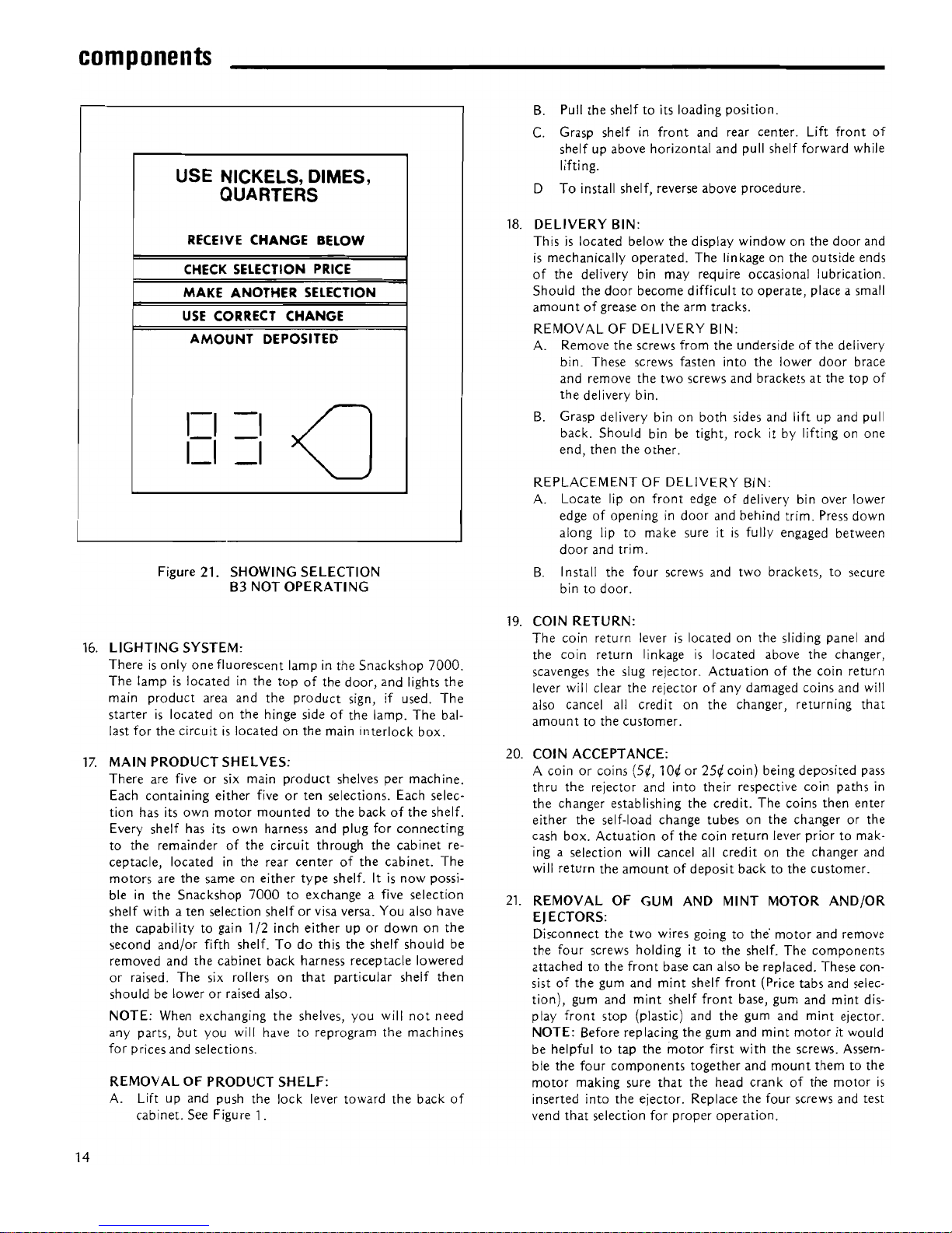
B.
Press
button14on
the
selection panel.Ifanyofthe
motors are
not
functioning (jammed, bad switch, bad
harness, etc.) the first non-functioning
motorinthe
series
will
be displayedonthe selection panel display
(Figure 21).
components
USE NICKELS, DIMES,
QUARTERS
RECEIVE
CHANGE
BELOW
•
CHECK
SELECTION
PRICE
•
MAKE
ANOTHER
SELECTION
•
USE
CORRECT
CHANGE
AMOUNT
DEPOSITED
1-11=11=11=1
1_1.1_1.1_1.1_1.
'-III
<J
1_1.1_1.
Figure 20.
C.
If
a non-functioning
motor
exists, record the selec-
tion on paper and repeat step
B.
Continue this pro-
cedure until
all
non-functioning selections have been
displayed, recorded and the selection panel display
reads
all
8's (Figure 20).
D.
If
all
motors are operational the selection panel dis-
play
will
read
all
8's.
E.
Inspect and repair the selections recorded from the
service diagnostic display.
F. After servicing the non-functioning selections return
all
shelves to a vend position and press the mode
switch
"operate"
button
locatedonthe front side
of
the sliding panel. A delay
will
occur before the oper-
ate L.E.D.
will
light. This delayisthe machine mak-
ing the automatic circuit scan. At the time the scan
is
taking place any motors
notinthe start position
automatically are homed. DO NOT TRY TO TURN
THE SPIRALS
BY
HAND. DAMAGE
TO
THE
MOTOR WILL RESULT.
G.
To
insure
that
all
serviced selections are operational,
repeat steps A and
B.
13
Page 17
components
USE NICKELS, DIMES,
QUARTERS
RECEIVE CHANGE BELOW
CHECK
SELECTION PRICE
MAKE ANOTHER SELECTION
USE
CORRECT CHANGE
AMOUNT
DEPOSITED
1=1
-I
<J
I_I
=1
Figure
21.
SHOWING
SELECTION
B3
NOT
OPERATING
16.
LIGHTING
SYSTEM:
Thereisonly
one
fluorescent
lampinthe
Snackshop
7000.
The
lampislocatedinthe
topofthe
door,
and
lights
the
main
product
area
and
the
product
sign, if used.
The
starterislocatedonthe
hinge
sideofthe
lamp.
The
bal-
last
for
the
circuitislocatedonthe
main
interlock
box.
17.
MAIN
PRODUCT
SHELVES:
There
are fiveorsix main
product
shelves
per
mach
ine.
Each
containing
either
fiveorten
selections.
Each
selec-
tion
has
its
own
motor
mountedtothe
backofthe
shelf.
Every
shelf
has its
own
harness
and
plug
for
connecting
to
the
remainderofthe
circuit
through
the
cabinet
re-
ceptacle,
locatedinthe
rear
centerofthe
cabinet.
The
motors
are
the
sameoneither
type
shelf. Itisnow
possi-
ble
in
the
Snackshop
7000toexchange
a five
selection
shelf
withaten
selection
shelforvisa versa.
You
also have
the
capabilitytogain
1/2
inch
eitherupor
downonthe
second
and/or
fifth
shelf.Todo
this
the
shelf
should
be
removed
and
the
cabinet
back
harness
receptacle
lowered
or
raised.
The
six rollers
on
that
particular
shelf
then
shouldbelowerorraised
also.
NOTE:
When
exchanging
the
shelves,
you
will
not
need
any
parts,
but
you
will havetoreprogram
the
machines
for
prices
and
selections.
REMOVALOFPRODUCT
SHELF:
A. Liftupand
push
the
lock
lever
toward
the
back
of
cabinet.
See Figure 1.
14
B.
Pull
the
shelftoits
loading
position.
C.
Grasp
shelfinfront
and
rear
center.
Lift
front
of
shelfupabove
horizontal
and
pull
shelf
forward
while
lifting.
D
To
install
shelf,
reverse
above
procedure.
18.
DELIVERY
BIN:
Thisislocated
below
the
display
windowonthe
door
and
is
mechanically
operated.
The
linkageonthe
outside
ends
of
the
delivery bin
may
require
occasional
lubrication.
Should
the
door
become
difficulttooperate,
place a small
amountofgreaseonthe
arm
tracks.
REMOVALOFDELIVERY
BIN:
A.
Remove
the
screws
from
the
undersideofthe
delivery
bin.
These
screws
fasten
into
the
lower
door
brace
and
remove
the
two
screws
and
bracketsatthe
top
of
the
delivery
bin.
B.
Grasp
delivery
binonboth
sides
and
liftupand
pull
back.
Should
bin be
tight,
rockitby
liftingonone
end,
then
the
other.
REPLACEMENT
OF
DELIVERY
BIN:
A.
Locate
liponfront
edgeofdelivery bin
over
lower
edgeofopeningindoor
and
behind
trim.
Press
down
along
liptomake
sureitis
fully engaged
between
door
and
trim.
B.
Install
the
four
screws
and
two
brackets,tosecure
bin
to
door.
19.
COIN
RETURN:
The
coin
return
leverislocatedonthe
sliding
panel
and
the
coin
return
linkageislocated
above
the
changer,
scavenges
the
slug
rejector.
Actuationofthe
coin
return
lever will clear
the
rejectorofany
damaged
coins
and
will
also cancel all
credit
on
the
changer,
returning
that
amounttothe
customer.
20.
COIN
ACCEPTANCE:
A
coinorcoins
(5¢,1O¢or25¢
coin)
being
deposited
pass
thru
the
rejector
and
into
their
respective
coin
paths
in
the
changer
establishing
the
credit.
The
coins
then
enter
either
the
self-load
change
tubesonthe
changerorthe
cash
box.
Actuationofth.e
coin
return
lever
priortomak-
ing a
selection
will cancel all
creditonthe
changer
and
will
return
the
amountofdeposit
backtothe
customer.
21.
REMOVAL
OF
GUM AND
MINT
MOTOR
AND/OR
EJECTORS:
Disconnect
the
two
wires goingtothe·
motor
and
remove
the
four
screws
holdingitto
the
shelf.
The
components
attachedtothe
front
base can also be
replaced.
These
con-
sist
of
the
gum
and
mint
shelf
front
(Price
tabs
and
selec-
tion),
gum
and
mint
shelf
front
base,
gum
and
mint
dis-
play
front
stop
(plastic)
and
the
gum
and
mint
ejector.
NOTE:
Before
replacing
the
gum
and
mint
motoritwould
be
helpfultotap
the
motor
first
with
the
screws. Assem-
ble
the
four
components
together
and
mount
themtothe
motor
making
sure
that
the
head
crankofthe
motor
is
inserted
into
the
ejector.
Replace
the
four
screws
and
test
vend
that
selection
for
proper
operation.
Page 18

22. REMOVAL OF GUM AND
MINT
SHELF:
Below
the
gum
and
mint
shelf
remove
the
two
screws
holding
the
gum
and
mint
receptacle
harness
bracket
(Page24Item 15). Loosen
the
other
two
screwsoneach
endofthe
gum
and
mint
pusher
stop strap (Page 34, Item
20)
and
disengageitfrom
the
cabinet. Grasp
the
shelf
and
pull
the
shelf
straight
out.
With
the
shelf
out
you
can
re-
place
the
gum
and
mint
pusher
(Page
34,
Item 31) by re-
movingthe
screw
(Page
34,
Item
21).
Reverse
the
pro-
ceduretoreplace
the
shelf.
Pay
special
attention
when
you
put
the
gum
and
mint
pusher
stop
strap
back
on that
all
the
gum
and
mint pushers have spring tension
and
are
behind
the
strap.
23. REMOVAL OF CONTROL PANEL:
The
entire
control
panel can be
removed
from
the
ma-
chinebyusing
the
following
procedure:
A. Pull paneltoits full
position.
B.
Remove
the
control
board
cover
and
power
board
cover.
C.
Disconnect
main
cabinet
harness
and
power
plugs
off
the
control
board.
D.
Remove
the
wrap
harness
screw
and
ground
screw
to
the
control
panel.
E.
Remove
the
top
stop
bracket
locatedonthe
upper
sideofroller
channel
assembly.
F. Grasp panel
to
support
its
weight
and
pull
forward
and
lift
upward.
Be
careful
that
the
roller
channel
does
not
fall
off
the
panel.
REPLACEMENTOFCONTROL
PANEL:
A. Engage
the
lower
edgeofthe
paneltothe
lower
guide
channel.
B.
Guide
the
roller
channel
onto
the
upper
track
and
lift
and
push panel
and
channel
into
the
cabinet.
C.
Reinstall
stop
bracket.
This
bracket
mustbeinstalled
in
backofthe
channelintopofthe
cabinet,
as this
bracketiswhat
stops
the
sliding panelinits
forward
position.
D.
Replace
the
cabinet
and
plug
harnessestothe
control
board.
The
Snackshop
7000 will
do
the
best
merchandising
job
for
you
if itiskept
clean.
The
display
window
can be
cleaned
with
any
good
glass
cleaner.
The
exterior
and
interior
surfaces
shouldbecleaned
with
warm
water
and
mild
detergent.
Rinse
thoroughlyandry
all surfaces.
CAUTION:
Do
not
use
any
cleaners
containing
silicon as
this
could
cause
electrical failures.
The
main
product
shelves can be
best
cleaned
with
the
spirals
and
product
spacers
removed.
Refertopage 5
for
removal
of
spirals
and
page 6
for
removalofthe
product
spacer.Wedo
have
cleaner
available
that
we feelissuperiortoany
other
components
E.
Replace
the
tie
wrap
harness
and
ground
screws.
F.
Replace
the
control
board
cover.
G. Push panel
back
into
the
cabinet.
cleaning
cleaners we have
triedinthe
past.
The
cleaner
(Part
# 460386)
comesina20ounce
aerosol can
andisusedbyspraying
a
good
coating
over
the
surfacetobe
cleaned,
then
letting
the
cleaner
set
for3to
3\-2
minutes
and
wipingitoff.
After
the
shelf
has
been
cleanedaneutralizer
(Part # 460387)
should
be
sprayed
on
and
wiped off.
The
neutralizer
will havetobe
transferedtoa smaller
bottle
with a
sprayer.
There
are
open-
ingsineach
endofthe
delivery
binatthe
back
for
cleaning
out
dirt.
Clean
the
acceptor
on
the
changer
frequenlyasaccumulated
dirtinthis
area can
cause
coinstohangornotbeaccepted.
Follow
recommended
cleaning
proceduresasdescribedbythe
manufacturer.
15
Page 19

regular snack spirals. A
product
pusher and spacer should
be
used where required. Part numbers for these special
spirals are as follows:
optional
equipment
1.
VENTILATING FAN: (Kit
#750102)
The
ventilating fan operates
on
115
volts and keeps a
steady flow
of
fresh air moving through the vendor
cabinet.
Installation
of
the ventilating blower takes
but
a few min-
utes and requires no additional wiring;
all
the vendors are
wired with a plug for
the
fan. Installation instructions are
sent with the kit.
400139
400140
400141
400142
400143
12 space special spiral
15 space special spiral
18 space special spiral
24
space special spiral
30
space special spiral
2. BASE KITS:
Base
kits are available to make the vendor compatible
with
other
manufacturers.
3.
GUM-AND-MINT:
Gum-and-Mint units are available
as
an option with Snack-
ship7000
vendors.
For information pertaining to loading
or
servicing gum-
and-mint unit, refer to this service manual for loading
instructions and for service instructions.
4. SPECIAL SPIRALS:
Special candy spirals are available for use
in
the five
(5)
selection snack shelves. For
the
sakeofidentification, the
back end
of
these spirals are colored RED and should
never be used
in
the ten (10) selection candy shelves.
These spirals allow vending
products
that
are
too
wide for
the standard candy columns
but
may be
too
thin for the
troubleshooting
NOTE: The difference between the standard candyspiral
and
the special candy spiral used
in
the
wide snack columnsisin
the overall lengthofthe spiral. The special spiralisshorter
than the standard candy spirals.
CAUTION:
Do
not
attempt
to use the special candy spirals
in
a ten (10) selection shelf.
5. SOUP DISPENSER. (Kit
750083)
A canned soup dispenserisavailableasan
option
for use
in
the five selection snack shelves. The dispenseriseasy
to install and holds up to nine cans
in
the unit.
6. DOLLAR BILL VALIDATORS:
There are two kinds of validators available Ardac (Part
#420147-4) and Mars (Part
#420147).
The validators
take but a few minutes to install and may also be pur-
chased through the manufacturer of that unit.
TROUBLE
CAUSE
REMEDY
16
Motor
runs
(2h
turns).
Motors
appear defective.
Spirals
turn
continuously.
Motors
runonsame
number
throughout
machine
A 1, B1,C1,
Dl,E1,Fl.
Cannot
set prices in
machine.
Push A & A 1
turns.
Push 8 & 81
turns.
No
L.E.D.
lightsoncontrol
board.
Press
the service mode
but
cannot
empty
changer.
Machine
will
not
accept coins.
G&M
selection shows
"Make
another
selection"
1.
Capacitor
discharging
current.
2. Defective
motor,
control
boardormotor
switch.
3. Loose
wireonmotor.
1.
Defective
transformer.
2. Defective
circuit
breaker.
3. Pin
connection.
1. Defective
control
board.
1.
Oneofthe
motor
wiresisshorting
aut.
1.
Defective
selection
switch
panel.
2. Defective
control
board.
1.
Selector
switch
panel shortin!\
out.
1. Check plugsoncontrol
board.
2. Defective
control
board.
1. Check plugsonthe
control
board.
2. Defective changer.
1.
No
powertomachine.
2. Defective changer.
3.
The
changer
will
accept
only
logical
amount
of
money
above the vend price.
4. Changer
shouldbeinstalled
with
power
off.
5. Machine accepts
only
one
coin.
6. Defective
power
board.
7. Defective
circuit
breaker
(115
volt).
1. Defective
motor.
1.
Resolder
capacitororreplace
motor.
2. Replace motor,
control
boardormotor
switch.
3. Replace
wire.
1. Check
for28volts
from
transformer
to
control
board.
1. Replace
board.
1. Check each
individual
motor
for
looseorpinched
wire
and replace
it.
1. Replace selection
switch
panel.
2. Replace
board.
1.
Replace selector switch panel assembly.
1. Plug
in.
2. Replace board.
1. Plug
in.
2. Replace changer.
1.
Check
wall
outlet.
2. Replace changer.
3. Check
pricing.
4.
Turn
power
off-then
on.
5. Check prices in the machine. Check
for
defective
circuit
breakers.
6. Replace
power
board.
7. Replace
circuit
breaker.
1. Replace
motor.
Page 20

bill
validator-instructions
for
installation
The
Service
Envelopeinthe
bottomofthe
machine
contains
different
mounting
brackets
and
decals
for
use
with
and
with-
out
bill
validators.
(Part
#460361)
The
machine,ifordered
withadollar
bill
validator,
will
already
have
the
unit
mounted
(MarsorArdac). If
for
some
reason
you
wantedtoexchange
unitsornot
use a
validator
at
all, we have
provided
these
brackets
and
decals.
MARS:
When installing a Mars
Validator
use the
dollar
decal
and
brackets
shownonthe
right. It
would
be easiertoinstall
the
bracketstothe
panel
with
the
hex
nuts
and
use
the
dollar
"empty"
light as a guide.
Take
the
four
screws
and
mount
the
Mars Val
idator
to
the
bracket
with
the
identification
label facing
out.
The
harness
then
can
be plugged
into
the
bottom
of
the
validator,tothe
stacker
and
plugged
into
the
bottom
pinsofthe
power
board,
andtothe
bottom
left
side
pins
of
the
main
Control
Board.
Bronze
(Part
#201433)
~eO-------;--
r-=-~-~._-
~....,,---~~-
.,
L_:)
~~_-----.£-....-2-J
WHEN LIT
•
USE COINS
$1PO
t
INSERT BILL
FACE
UPASSHOWN
t
ARDAC:
When installing an
Ardac
Validator
use
the
decal
and
plate
shown
on
the
right. Using
the
dollar
"empty"
light as a
guide
mount
the
plate
with
the
four
hex
nuts.
Mount
the
validatortothe
place
with
four
more
hex
nuts. Insert
the
stackerinthe
validator
(making
sure itislocked
into
place).
Mount
the
control
box
onto
the
studs
providedtothe
left
of
the
coin
cup
chute
and
fasten itonto
the
panel
with
two
screws.
The15pin plugonthe
left
sideofthe
control
box
goes
overtoeither
oneofthe
stacker
plugs.
The15pin
plug
on
topofthe
control
box
goes
overtoeither
oneofthe
plugs
on
the
validator.
The
120
volt
plugonthe
topofthe
control
box
goestothe
bottom
two
right pinsonthe
power
board.
The
21
pin
plug goesupto
the
bottom
left pinsofthe
main
Control
Board.
NO V
ALiDATOR:
Use
the
decal
and
bracketasshown.
The
short
solid
bracketisusedtofill
the
hole
on
the
control
panel.
Insertthis
bracket
and
hold
it against
the
panel with
the
Ardac
mounting
plate.
(Part
#201463)
~\-----ol
,
J
(Part
#201418)
(Part
#460358)
WHEN LIT
llit.
,-'
I·
!!
•
~.~i~
USE COINS
~·T
CO>
I
~~~
~
A~~~l\
$1PO
INSERT BILL FACE
UP
AS SHOWN
t
t
(Part
#460359)
17
Page 21

.--
9
8
11
12
10
2
-=-
T
+
[Gl
SNACKS
t
1----
f---o
...
,
,-
13
51
00
..
ACCEPTS
$1
BILLS
, ,
B
~
F
lJS}J
D
10-
[7
<
A.P.
VINYL
PANELS
AND
OTHER
STYLINGS
See
Pages
39-47
""
--1/
3
6
5
4
7
18
Page 22

___________________
door-outside
front
Item
No.
Part
No.
Description
1
340044-5
Top,
Trim,
For
use
wNinyllnsert.
201690-4
Top
Trim
For
Use
wNinyllnsert, Export
Only.
2
440258-2
Insert,
Top
Trim,
Snacks.
420185
Insert,
Top
Trim,
Export
Only.
3
340057
Trim,
Outside
Vertical
(RightorLeft).
4
340058-2
Trim,
Inside
Vertical
(RightorLeft).
5
750141
Window,
Front.
(44-5/8x26-7/8
x
1/8).
Note:
Replacement
glass
must
be
hard
temperedorLexan
only.
6
340058
Trim,
Inside
Horizontal.
7
340055-3
Trim,
Inside
Horizontal.
8
440296
Coin
Cup
Trim.
Black
Plastic.
9
420071
Ace
Lock
w/2
Keys.
420071-1
Ace
Lock
w/1
Key.
420071·2
Ace
Lock
wlo
Key.
10
660319
Lock
Handle
Assembly.
W/Lock
Arm
and
Nut.
11
320055
Trim,
Control
Ring.
12
600428
Door
Only.
Specify
Color.
13
460375
Dollar
Decal.
19
Page 23

door-inside
front
_
432
1
34
5
6
7
6
3
I I I
I
I
_.c:=!
=
J
I
~
o=lmlll., I
t
".
"
,
P
11--2
5
5
~
0
-
'---=
0
28
n
~
~
-==
J
I~
Q
.
28
~32
31---1
~
~
@
til
ell--
21
-
.
9
29
0 @
If
.
0
~
28
29
30
20
<:)
1 1
\11
e
\t)
\!l
____
\t)
e
e
~
2
q
•
5
""
-2
I~
0
W
6
..
..
-
~
IU
L-..-
f:=
0
2
~1Jr'-,
[
2
24
~L
C
~
J
rj---
f
-=c==
8
6
5
7
9
21
14
20
21
22
20
Page 24

•
____________________
door-inside
front
Item
No.
Part
No.
Description
1
460041-1
Insulation,
Foam
(1/4 x
1/4
x 50").
2
380022
Lamp,
Fluorescent
(F18T8-CW-K30)
3
380047
Socket,
Fluorescent
Lamp
Only.
680138
Assembly
Complete.
Lamp
Harness.
4
380023
Starter.
FS-25.
380023-4
Starter.
F5-11,
Export
Only.
5
201-6R7
Screw
Rd.
Hd.
Phillips
Type
B
(6-18
x 7/16).
6
460308
Label
FCC.
7
460085
Decal,
Patent.
8
400112
Spring,
Locking
Bar.
9
276-6R6
Screw,
Pan
Hd.
Self-Tap
(6-32
x 3/8).
10
118-10-8
Carraige
Bolt (#10-24 x 1/2).
11
660319
Assembly
Complete.
Lock
Handle.
W/Lock
Arm
and
Nut.
420146
Lock
Handle
Only.
12
404-10
Nut,
Hex
(10-24).
13
640131
Lock
Arm
Only.
14
600432
Locking
Bar
only.
15
18443
Nut,
Hex
Hd.
(8-32).
16
201155
Coin
Return
Cup.
201156
Coin
Return
Cup
Door.
20
276-8R6
Screw,
Pan
Hd.
Self-Tap
(8-32
x 3/8).
I
Item
No.
Part
No.
Description
21
200-6R6
Screw,
Rd.
Hd.
Phillips
Type
A
(6-18
x 3/8).
22
640108
Lower
Hinge.
420003
Screw,
Flat
Hd.
(1/4 -20x 3/4).
23
400095
Door
Stop.
24
300156
Nut,
Special.
420010-10
Washer.
114-41-8
Screw,
Hex
Hd.
Mach.
(1/4-20
x 1/2).
25
660310
Assembly,
Delivery
Bin
Complete.
(See
Page34for
Itemized
Parts)
26
420097
Cord
Clip.
27
200906
Delivery
Bin
Anchor
Strap.
28
201-6R11
Screw,
Rd.
Hd.
Phillips
Type
B
(6-20 x 11/16 )
29
460436
Insulation,
Rubber.
Black.
(0
rder
numberofinches
needed)
30
201384
Bottom
Window
Clamp.
31
201381-3
Window
Side
Shield
(clamp)
Pivot.
32
201381-2
Window
Side
Shield
(clamp)
Lock.
33
640107-1
Assembly,
Upper
Hinge.
420003-1
Screw,
Flat
Hd.
(1/4-20
xl/2).
34
440084
Light Reflector.
I
21
Page 25

cabinet
=======-----
39
33
23
46
7
44
42
31
"'------
32
2
---
/
29
<
41;>
/\
5 6
3
22
Page 26

________________________
cabinet
Item
No.
Part
No.
Description
1
750100·2
Cabinet
Assembly
complete
with
legs.
Specify
color.
2
600310
Assembly,
Cabinetto0
oar
Filler.
Specify
Color.
3
276-8R6
Screw,
Pan
Hd.
Self·Tap
(8-32
x 3/8).
4
600195
Leg
Assembly
Rear.
5
114-51-12
Screw,
Hex
Hd.
Mach.
(5-16-18
x 3/4).
6
300103
Leg
Leveler.
7
600302
Leg
Assembly
Front.
Pivot
Side.
8
201012
Lower
Hinge
Support.
9
420003
Screw
Flat
Hd.
(1/4-20 x 3/4).
10
300156
Nut,
Special.
Door
Stop
Anchor.
11
400095
Door
Stop.
12
420010-10
Washer.
13
114-41-8
Screw,
Hex
Hd.
Mach.
(1/4-20
x 1/2).
14
440204
Door
Stop
Friction
Pad.
15
201042
Door
Stop
Plate.
16
277-10R16
Screw,
Pan
Hd.
Self-Tap
(10-32
xl").
17
600197
Leg
Assembly
Front.
Lock
Side.
18
660312-7
Assembly
Complete.
Left
Side
Panel.
5
Shelf.
600417
Panel
Only. Left
Side.5Shelf.
660312-12
Assembly
Complete.
Left
Side.6Shelf.
600418
Panel
Only. Left
Side.6Shelf.
19
201450
Filler, G& M Pivot
Side.
20
201386
G&M
Filler
Panel.
(Use
without
G&M
Shelf).
21
437-41
Nut,
Keps
(1/4 -
28).
22
300137
Screw,
Shelf
Roller
23
440278
G&M
Tray
Slide.
Item
No.
Part
No.
Description
24
440264
Front
Roller
Guide,
Left
Side.
25
276·8R12
Screw,
Pan
Hd.
Phillips
(8·32
x 3/4).
26
201389
Roller
Retainer.
27
440263
Front
Roller
Guide.
Right
Side.
28
440161
Shelf
Lock.
29
660311-5
Assembly
Complete.
Right
Side
Panel.
5
Shelf.
600415
Panel
Only.
Right
Side.5Shelf.
660311-6
Assembly
Complete.
Right
Side
Panel.
6
Shelf.
600416
Panel
0nly. Right
Side.6Shelf.
30
750102
Kit,
Complete.
Ventilating
Fan.
680313-2
Assembly,
Fan
Complete
Only.
31
420040-6
Snap
Bush
ing.
32
277-10R8
Screw,
Pan
Hd.
Self-Tap
(8-32
x 1/2).
33
750102
Kit,
Assembly,
Complete.
750102-1
Kit,
Complete
Ventilating
Fan,
Export
Only.
680313-1
Assembly
Fan
Complete
Only,
Export.
640118
Assembly,
Fan
Chute
Only.
34
201176
Fan
Screen.
35
420023
Wing
Nut
(8-32).
36
380215
Fan,
Finger
Guard.
37
640107-1
Top,
Hinge
Assembly.
38
42003-1
Screw,
Flat
Hd.
(1/4-20 x
112).
39
201382
Fan
Hole
Cover.
40
404-8
Nut,
Hex
Hd.
335-8R6
Screw,
Pan
Hd.
Tap
Tite Phillips.
41
(8-32
x 3/8).
42
164·51-7
Screw,
Hex
Hd.
Sems
(5-16-18
x 3/8).
43
201383
Panel,
Left
Side
Extension.
44
201550
Plate,
G&M
Filler.
Deflector.
45
640154
Assy.
Lower
Door
Plate.
46
420010-18
Washer1V4
47
440306
Shelf
Guide
Button.
23
Page 27

cabinet
=======~-
32
6
7
8
9
24
Page 28

-------
cabinet
Item
No. Part
No.
Description
1
750100-2
Cabinet
Assembly
Complete.
w/Legs
7000.
Specify
Color.
2
420142
Pin,
Cabinet
Receptacle.
3
680303
Cabinet
Harness
Complete.5Shelf.
680304
Cabinet
Harness
Complete.6Shelf.
4
201373
Receptacle
Mounting
Plug.
5
276-8R6
Screw,
Pan
Hd.
Self·Tap
(8-32
x 3/8).
6 420040·7
Snap
Bushing
1-5/8
Diameter.
7
300167
Pin.
8
420045
Rubber
Bumper.
9
680270-3
Assembly
Complete
Main
Junction Box.
(See
Page36for Itemized
Parts)
10
660240-1
Assembly
Complete.
Cord
Set.
680321-1
Assembly, Complete
Cord
Set, Export Only.
660386
Assembly Complete, Grounding, Export Only.
1D0-B41-24
Brass Screw, Export Only.
(1/4
x 20 x 11/2).
404-B41
Brass Nut, Qty. 4, Export Only.
(1/4
x 20)
380224 KeeperWasher, Qty.4,Export Only.
630·416
Lock Washer,
1/4,
Export Only.
11
420040-4
Snap
Bushing.
1-5/16
Diameter.
12
276-8R6B
Screw,
Pan
Hd.
tf23
Phillips
(8-32
x 3/8).
13
360083
Transformer.
360094 Transformer, Export Only.
14
201453
Gum
&Mint Tray
Catch.
15
201415
Gum
&Mint Mounting
Bracket
Plug.
201415-1
Gum & Mint MountingBracket Plug.
Export Only.
16
380230
Plug
Only.
17
277-10R8
Screw
Pan
Hd.
Phillips
Type
23.
(10-32
x 1/2).
Item
No. Part No.
Description
18
660316
Gum
& Mint
Shelf
Complete.
(See
Page32for Itemized
Parts).
19
600435
Lower
Guide
Channel.
20
600179-1Cash
Box
w/Handle.
21
600436
Cash
Box
Mounting
Bracket.
22
(See
Page26for Itemized
Parts.)
23
201563
Control
Panel
Stop.
24
200816
Roller
Channel
Stop
Bracket.
25
600433
Door
Lock
Catch.
Heavy
Duty.
26
300137
Screw,
Shelf
Roller.
27
440277
Shelf
Roller.
28
660318
Assembly
Complete.
Roller
Channel.
201431
Roller
Channel
Only.
29
600434
Roller
Channel
Mounting
Bracket.
Upper.
30
750097
Lock
and
Cam
for
Cash
Box.
w/2
keys.
Specify
Number.
420020
Lock
w/1
key.
Specify
Number.
420069
Cam
Cash
Box
Locking
only.
31
201562
Control
Panel
Stop
Bracket.
32
750146
Kit Anchoring Bracket. (Consistsof2 Brackets
with Hardware).
202016
Anchoring
Bracket
only.
33
118-41-12
Carriage
Bolt
(114-20x314).
410-41
Hex
Nut
(114-20)
Not
shown.
600-416
Plain
Washer.
(1/4)
Not
shown.
25
Page 29

3
10
20
24
26
27
1
40 3
39
/
31
30
36
32
26
Page 30

•
_____________________
control
panel
Item
No.
Part No. Description
1
600439
Control
Panel
Only.
2
201461
Control
Board
Cover.
3
276-8R6
Screw,
Pan
Hd.
#23
Phillips
(8-32
x 3/8).
276-8
R8
Screw,
Pan
Hd.
Type23Phil.
(#8x1/2)
(Use
With
Bill
Validator).
4 460357
Control
Board
Decal.
5 360109
Main
Control
Power
Board.
6
201457
Power
Board
Cover.
460360
Decal
"Caution"
High
Voltage.
7
437-41
Nut,
Keps_
(1/4 x
28).
8
440277
Shelf
Roller.
9 300137
Screw,
Shelf
Roller.
10
750115-2
Main
Control
Board
only.
750115-3
Control
Board
with0igital.
360112
Main Control Board, Export Only.
360111
Control Boards, 4 pes., ExportOnly.
11
680303
Cabinet
Harness.
Assembly
Complete.
5
Shelf.
680304
Cabinet
Harness.
Assembly
Complete.
6 Shelf.
12
380078
Tie
Wrap
Harness.
13
680309
Coinco
Changer
Hook-Up
Harness.
14
201130
Changer
Plug
Mounting
Bracket.
15
680308
Mars
Changer
Hook-Up
Harness.
680319
Mars
Changer
Hook-Up Harness,
Export Only.
16
420096
Harness
Clamp.
17
600422
Assembly
CoinInlet
Chute.
18
400034
Spring.
19
751-25
Retaining
Ring.
20
201459
Return
Button
Link.
460374
Decal,
Return
Button
Link
(not
shown).
21
201401
Coin
Return
Bracket.
22
660323
Coin
Return
Button
with
Decal.
23
460356
Decal
Only.
24
600423
Assembly,
Coin
Cup
Chute.
25
420097
Harness
Clamp.
Item
No. Part No. Description
26
660333
Kit,tomount
all
Brackets
for Validators
with
Decals.
201418
Dollar
Filler
Plate.
For
Use
Without
Dollar
Acceptors.
27
640126
Bracket,
Dollar
Acceptor
Mounting
(Ardac
only).
28
201517
Bracket,
Dollar
Acceptor
Mounting.
Upper
201518
Bracket,
Dollar
Acceptor
Mounting.
Lower
201433
Bracket,
Dollar
Acceptor
Mounting.
(Mars
Only).
29
420144
Ferrule.
30
640124
Control
Panel
Front
Only.
31
660266-1
Assembly,
Selector
Switch
Panel.
32
460358
Decal,
Dollar.
For
use
with
Ardac
Dollar
Acceptor
Only.
460359
Decal,
Use
withNoDollar
Acceptor.
460361
Decal,
Dollar.
For
use
with
Mars
Dollar
Acceptor
Only.
33
320054
Trim,
Button
and
Coin
Entrance.
34
440279
Coin
Entry
Trim.
460362
Coin's
Decal.
(not
shown).
460363
Coin
Decal.
35
440225
Selector Button.
36
440275
Glass
Coin
Instruction.
5",
10(
25i!· $1.00.
440276
Glass
Coin
Instruction.
51!,
10i!
- 25{
440283 Glass Coin Instruction, England.
440286 Glass Coin Instruction, Australia.
440319 Glass Coin Instruction, German.
440323 Glass Coin Instruction, Dutch.
37
380240
Dollar
Light,
"Empty"
38
380239
Door
Operate
Mode
Switch.
39
600-8
Washer
(No.8).
40
660289
Assembly,
Plastic
Coin
Chute.
600459
Assembly,
Metal
Coin
Chute.
41
360106
Digital
Display
Board.
360097
Connector
Ribbon
(not
shown).
42
438-8
Nut
Hex
(8-32).
43
680307
Harness,
Selector Switch.
44
300168
Screw,
Changer
Mounting.
45
420095
Control
Board
Stand-offs.
46
200816
Bracket,
Roller
Channel
Stop.
47
201466
Control
Panel
Front Stiffener.
27
Page 31

snack
shelf
28
Page 32

Item
No.
Part
No.
Description
1
750121
Assembly
Complete.
Snack
Shelf.
w/o
Spirals.
600240-2
Snack
Shelf
Only.
2
750106
Vend
Motor
Complete.
3
440287
Spiral
Lock
4
300137
Screw,
Shelf
Roller.
5
440277
Roller,
Shelf.
6
437-41
Nut,
Keps.
(1/4·28).
7
440285
Price
and
Selection
Tab
Holder.
8
460346
Item
Tabs.
9
460347
Price
Tabs.
Assorted
lOt -
$1.50.
460347·1
Price
Tabs.
All 30t - 35t.
460347-2
Price
Tabs.
All 40t -45t.
460347-3
Price
Tabs.
All 50t - 55t.
460347-4
Price
Tabs.
All 60t . 65t.
460347·5
Price
Tabs.
All 70t -75t.
460347·6
Price
Tabs.
All 80t - 85t.
460347-7
Price
Tabs.
All 90t . 95t.
460347·8
Price
Tabs.
All
$1.00-$1.05.
460347-9
Price
Tabs.
All
$1.10.$1.15.
460347-10
Price
Tabs.
All
$1.20-$1.25.
460347-11
Price
Tabs.
All
$1.30-$1.35.
460347-12
Price
Tabs.
All $1.40 -
$1.45.
460347-13
Price
Tabs.
All $1.50 .
$1.55.
460347-14
Price
Tabs.
All $1.60 -
$1.65.
460347-15
Price
Tabs.
All
$1.70-$1.75.
460347-16
Price
Tabs.
All $1.80 -
$1.85.
460347·17
Price
Tabs.
All $1.90·
$1.95.
460347-18
Price
Tabs.
All $2.00·
$2.05.
460347-19
Price
Tabs
All
$2.10·
$2.15.
460347·20
Price
Tabs
All
$2.20-$2.25.
460347-21
Price
Tabs
All
$2.30-$2.35.
460347-22
Price
Tabs
All
$2.40-$2.45.
460347-23
Price
Tabs
All
$2.50·
$2.55.
460347·24
Price
Tabs
All
$2.60-$2.65.
460347-25
Price
Tabs
All
$2.70-$2.75.
460347-26
Price
Tabs
All
$2.80-$2.85.
460347-27
Price
Tabs
All
$2.90-$2.95.
460347·28
Price
Tabs
All
$3.00-$3.05.
10
305-8R6
Screw,
Pan
Hd.
Phillips,
Plastite
(8·16
x 3/8).
snack
shelf
Item
No.
Part
No.
Description
12
640101
Spacer,
Snack
Shelf.
13
660330-2
Assembly
Product
Rail.
For
use
w/Pastry
Spiral.
440148-1
Plastic
Product
Rail
Only.
14
750083
Kit,
Can
Dispenser
Assembly.
15
400127
10
Space
Snack
Spiral.
400127-1
10
Space
Snack
Spiral,
Chrome.
400128
12
Space
Snack
Spiral.
400128-1
12
Space
Snack
Spiral,
Chrome.
400129
15
Space
Snack
Spiral.
400129-1
15
Space
Snack
Spiral,
Chrome.
400136
30
Space
Snack
Spiral.
400136-1
30
Space
Snack
Spiral,
Chrome.
400137
40
Space
Snack
Spiral.
400137-1
40
Space
Snack
Spiral,
Chrome.
400153
7
Space
Snack
Spiral.
400153-1
7
Space
Snack
Spiral,
Chrome.
400162
6
Space
Snack
Spiral.
400162-1
6
Space
Snack
Spiral,
Chrome.
400163
18
Space
Snack
Spiral.
400163-1
18
Space
Snack
Spiral,
Chorme.
16
276-8R6
Screw,
Pan
Hd.
Self-Tap
(8-32
x 3/8).
17
420142
Pin,
Shelf
Plug.
18
680301
Harness,
Complete.
Pastry
Shelf.
19
600246-1
Bracket
0nly.
20
305·7
R8
Screw,
Pan
Hd.
Phillips,
Plastite.
(7x1/21.
21
440201
Orive
Cam.
Rear.
22
751-31
Retaining
Ring.
#31.
23
440200
Drive
Cam.
Front.
24
640109
Cam,
Mounting Brkt. &
Spring
Assembly.
25
600308
Can
Dispenser,
Trough
Only.
26
300184
Shoulder
Bushing.
277-10R8
Screw,
Type23(#10·32 x 1/2l.
27
400094
Actuator
Wire.
28
440196
I
Price
and
Selection
Trim.
29
440199
Stop
Lever.
30
440198
Leg,
Top
Can
Guide&Sign
Trim.
31
440197
Top,
Can
Guide&Sign
Trim.
32
440125
Spiral
Retainer
Only.
35
201534
Front
Support
Only.
36
200913-1
Rear
Support
Bracket
Only.
Use
w/Pastry
Spiral.
200913
Rear
Support
Bracket
Only.
Use
w/Special
Candy
Spiral.
29
Page 33

11
20
25
2
candy
shelf
=============------
30
Page 34

_____________________
candy
shelf
Item
No.
Part
No.
Description
1
750122
Assembly,
Complete.
Candy
Shelf.
wlo
Spirals.
600239-1
Candy
Shelf
Only.
2
750106
Vend
Motor
Complete.
360135
Vend
Motor
Half
Cycle.
3
440287
Spiral
Lock
5
300137
Screw,
Shelf
Roller.
6
440277
Roller,
Shelf.
7
437-41
Nut,
Keps.
(1/4x28).
8
460346
Item
Tabs.
9
460347
Price
Tabs.
Assorted
lOe.$1.50.
460347-1
Price
Tabs.
All
30e-35e.
460347-2
Price
Tabs.
All
40e-45e.
460347-3
Price
Tabs.
All
50e-55e.
460347-4
Price
Tabs.
All
60e-65e.
460347-5
Price
Tabs.
All
70e-75e.
460347·6
Price
Tabs.
All 80t -
85e.
460347-7
Price
Tabs.
All 90t -
95e.
460347·8
Price
Tabs.
All
$1.00-$1.05.
460347·9
Price
Tabs.
All
$1.10-$1.15.
460347-10
Price
Tabs.
All
$1.20-$1.25.
460347-11
Price
Tabs.
All $1.30·
$1.35.
460347-12
Price
Tabs.
All $1.40·
$1.45.
460347·13
Price
Tabs.
All
$1.50-$1.55.
460347-14
Price
Tabs.
All
$1.60-$1.65.
460347-15
Price
Tabs.
All
$1.70-$1.75.
460347-16
Price
Tabs.
All
$1.80-$1.85.
460347-17
Price
Tabs.
All
$1.90-$1.95.
460347-18
Price
Tabs.
All
$2.00-$2.05.
460347·19
Price
Tabs
All
$2.10-$2.15.
460347·20
Price
Tabs
All
$2.20-$2.25.
460347-21
Price
Tabs
All
$2.30-$2.35.
460347-22
Price
Tabs
All
$2.40-$2.45.
460347-23
Price
Tabs
All
$2.50-$2.55.
460347-24
Price
Tabs
All
$2.60-$2.65.
460347-25
Price
Tabs
All
$2.70·
$2.75.
460347-26
Price
Tabs
All
$2.80-$2.85.
460347-27
Price
Tabs
All
$2.90-$2.95.
460347-28
Price
Tabs
All
$3.00-$3.05.
Item
No.
Part
No.
Description
10
440262
Price
and
Selection
Tab
Holder.
Off
Set
11
660178
Assembly
Candy
Spacer.
660178-4
Assembly
Candy
Spacer.
Export.
Use
w/Half
Cycle
Motor.
12
440141·1
Candy
Product
Pusher.
13
660503
Product
Guide
Assembly.
For
use
wIThin
Mints.
14
400120
12
Space
Candy
Spiral.
400120-1
12
Space
Candy
Spiral,
Chrome.
400121
15
Space
Candy
Spiral.
400121-1
15
Space
Candy
Spiral,
Chrome.
400122
18
Space
Candy
Spiral.
400122·1
18
Space
Candy
Spiral,
Chrome.
400123
24
Space
Candy
Spiral.
400123-1
24
Space
Candy
Spiral,
Chrome.
400135
30
Space
Candy
Spiral.
400135-1
30
Space
Candy
Spiral,
Chrome.
400138
40
Space
Candy
Spiral.
400138-1
40
Space
Candy
Spiral,
Chrome.
400164
7
Space
Candy
Spiral.
400164-1
7
Space
Candy
Spiral,
Chrome.
400166
9
Space
Candy
Spiral.
400166-1
9
Space
Candy
Spiral,
Chrome.
400167
6
Space
Candy
Spiral.
400167-1
6
Space
Candy
Spiral,
Chrome.
400168
10
Space
Candy
Spiral.
400168-1
10
Space
Candy
Spiral,
Chrome.
15
276-8R6
Screw,
Pan
Hd.
Self-Tap
(8-32
x 3/8).
16
420142
Pin,
Shelf
Plug.
17
680299
Harness,
Complete.
Candy
Shelf.
18
600246·'
Bracket
Only.
19
305·7R8
Screw,
Pan
Hd.
Phillips
Plastite
(#7 x
1/2)
20
660191
Assembly
Product
Rail.
For
use
w/Candy
Spiral.
440148-1
Plastic
Product
Rail
Only.
21
440125
Spiral
Retainer
Only.
24
201258
Front
Support
Only.
25
200913
Rear
Support
Bracket
Only.
31
Page 35

convertible
shelf
15
32
1
11
-~~---10
Page 36

Item
No.
Part
No.
Description
1
750147
Assembly
Complete.
Convertible
Shelf.
(5
Snack
Selections).
Wlo
spirals.
750147-1
Assembly
Complete.
Convertible
Shelf.
(4
Snack
Selections
and2Candy).
Wlo
spirals.
750147-2
Assembly
Complete.
Convertible
Shelf.
(3
Snack
Selections
and4Candy).
Wlo
spirals.
750147-3
Assembly
Complete.
Convertible
Shelf.
(2
Snack
Selections
and6Candy).
Wlo
spirals.
750147-4
Assembly
Complete.
Convertible
Shelf.
(1
Snack
Selection
and8Candy).
Wlo
spirals.
750147-5
Assembly
Complete.
Convertible
Shelf.
(10
Candy
Selections).
600240-2
Convertible
Snack
Shelf
Only.
2
300137
Screw,
Shelf
Roller.
3
440277
Roller,
Shelf.
4
437-41
Nut,
Keps
(1/4
x
28).
5
305-8R6
Screw
Pan
Hd.
Phillips.
Plastite
(8-16
x
3/8).
6
460346
Item
Tabs.
7
460347
Price
Tabs.
Assorted
10¢-$1.50.
460347-1
Price
Tabs
All
30¢
-
35¢.
460347-2
Price
Tabs
All
40¢
-
45¢.
460347-3
Price
Tabs
All
50¢
-
55¢.
460347-4
Price
Tabs
All
60¢
-
65¢.
460347-5
Price
Tabs
All
70¢
-
75¢.
460347-6
Price
Tabs
All
80¢
-
85¢.
460347-7
Price
Tabs
All
90¢
-
95¢.
460347-8
Price
Tabs
All
$1.00-$1.05.
460347-9
Price
Tabs
All
$1.10-
$1.15
460347-10
Price
Tabs
All
$1.20-$1.25.
460347·11
Price
Tabs
All
$1.30-$1.35.
460347-12
Price
Tabs
All
$1.40-$1.45.
convertible
shelf
Item
No.
Part
No.
Description
460347-13
Price
Tabs
All
$1.50-$1.55.
460347-14
Price
Tabs
All
$1.60-$1.65.
460347-15
Price
Tabs
All
$1.70-$1.75.
460347-16
Price
Tabs
All
$1.80-$1.85.
460347-17
Price
Tabs
All
$1.90-$1.95.
460347-18
Price
Tabs
All
$2.00-$2.05.
460347-19
Price
Tabs
All
$2.10-$2.15.
460347-20
Price
Tabs
All
$2.20-$2.25.
460347-21
Price
Tabs
All
$2.30-$2.35.
460347-22
Price
Tabs
All
$2.40-$2.45.
460347-23
Price
Tabs
All
$2.50-$2.55.
460347-24
Price
Tabs
All
$2.60-$2.65.
460347-25
Price
Tabs
All
$2.70-$2.75.
460347-26
Price
Tabs
All
$2.80-$2.85.
460347-27
Price
Tabs
All
$2.90-$2.95.
460347-28
Price
Tabs
All
$3.00
-
$3.05.
8
440262
Price
and
Selection
Tab
Holder,
Offset
Candy.
(Please
see
Page31Item
#14
for
Candy
Spirals).
9
440285
Price
and
Selection
Tab
Holder,
Snack.
(Please
see
Page29Item
#15
for
Snack
Spirals).
10
200753-2
Shelf
Divider.
Candy.
11
660178
Assembly
Candy
Spacer.
12
276-8R6
Screw
Pan
Hd.
Self-Tap
(B-32x3/8).
13
420142
Pin,
Shelf
Plug.
14
660337
Harness,
Candy
Shelf
with
Plug
Bracket.
15
750106
Vend
Motor
Complete.
18
305-7RB
Screw,
Pan
Hd.
Phillips,
Plastite(7x
1/2).
19
440287
Spiral
Lock.
33
Page 37

.....
-
Q)
.c
en
....,
C
.-
E
olS
E
:::s
en
C)
N
N
~
N
M
N
~
M
...
'<t
I")
Page 38

Item
No.
Part No.
Description
1
660316
Assembly
Complete.
Gum&Mint
Shelf.
660316-2
Assembly Complete.
Gum
& Mint Shelf,
Export Only
600420
Gum
and
Mint
Shelf
Only.
600460
Gum
and
Mint Shelf
Only,
Export.
2
420040-9
Snap
Bushing
and
Hole
Plug.
3
201412
Thin
Mint
Adapter(2per
selection).
4
201458
Gum
and
Mint
Rear
Pusher
Stop.
201458-2
Gum
and
Mint
Rear
Pusher Stop, Export
Only.
5
276·8R6
Screw,
Pan
Hd.
Self·Tap
Phillips
(8·32
x 3/8).
6
217-8R22
Screw,
Pan
Hd.
Phillips
TypeAB(1-3/8).
7
300184
Shoulder
Bushing.
277-10R8
Screw
Type23(#10-32 x 1f2).
8
201454-1
Gum
and
Mint
Shelf
Latch.
Left
Side.
9
360105
Gum
and
Mint Motor.
10
420089
Screw,
1000Flat
Hd.
(6-32
x 1/2l.
11
600427
Gum
and
Mint
Plug
Mounting
Bracket.
12
440267
Ejector,
Gum
and
Mint.
13
440266
Gum
and
Mint
Shelf
Front
Base.
14
305-7R16
Screw,
Pan
Hd.
Plastite
(#7 x
n.
15
460352
,
Decal,
Gum
and
Mint
Shelf
Latch.
440270
I
Display
Stop.
Gum
and
Mint
Column
16
Front.
17
440273
Gum
and
Mint
Shelf
Front.
Item
No.
Part No.
Description
18
305-7R22
Screw,
Pan
Hd.
Plastite
(#7x1-3/8).
19
680305
Harness,
Gum
and
Mint
Shelf.
380229
Gum
and
Mint
Shelf
Plug
Only.
660340-1
Harness
G& M
Shelf&Bracket,
Export
Only.
680322
Harness
Only.
Export.
20
201414
Strap,
Gum
and
Mint
Pusher
Stop.
201527
G& M
Pusher
Stop
Strap,
Export
Only.
21
262-6R5
Screw,
Flat
Hd.
Phil.
Type23(6-32x5/16).
22
400106
Spring,
Gum
and
Mint
Pusher
Return.
23
660314
Assembly,
Complete
Gum
and
Mint
Display
Hinge.
660314-1
Assembly,
Complete
Gum
and
Mint
Display
Hinge,
Export
Only.
24
201454
Gum
and
Mint
Shelf
Latch.
Right
Side.
25
420023
Wing
Nut
(8-32).
26
201411·1
Column
Spacer,
Left.
27
201411
Column
Spacer.
Right.
28
420296
Shelf
Grommet.
(NGS#122).
29
460351
Decal
Caution.
Gum
and
Mint
Shelf.
30
201409
Cover
Gum
and
Mint
Shelf.
201530
Cover
Gum
and
Mint Shelf, Export
Only.
31
660313
Assembly,
Complete.
Gum
and
Mint
Pusher
and
Spring.
32
801C-125-12
Roll
Pin
(1/8x3/4).
33
440265
Pusher
Only.
34
440274
Roller,
Gum,
and
Mint
Pusher.
35
201691
Shelf
Closer.
35
Page 39

delivery
bin
_
36
6
9
Page 40

_____________________
delivery
bin
Item
No.
Part
No.
Description
660310
Delivery
Bin
Assembly.
Complete.
1
600407
Delivery
Bin.
2
750161-1
Assembly
Complete.
Delivery
Bin
End
(Lock
Side).
640099
Arm
Mounting
Bracket
(Lock
Side).
3
438-8
Nut,
Keps.
No.
8-32.
4
640098
Inner
Door
Bin
Arm.
5
640100
Bin
Door
Drive
Assembly
(Lock
Side).
6
751-37
Retaiiling
Ring
No.
37.
7
276-8R6
Screw,
Pan
Hd.
Phillips.
Self
Tap.
No.
8-32
x 3/8".
8
640097
Door
Drive
Arm.
Item
No.
Part
No.
Description
9
440129
Door
Bearing.
10
200763
Inner
Door.
12
600258
Door,
Delivery
Bin.
13
420029
Rubber
Bumper.
14
640100·1
Bin
Door
Drive
Assembly
(Pivot
Side).
15
750161
Assembly
Complete.
Delivery
Bin
End
(Rivot
Side).
640099·1
Arm
Mounting
Bracket.
(Pivot
Side).
16
200902
Baffle,
Rear
Delivery
Bin.
17
200906
Del
iveryBin
Anchor
Strap.
18
660238
Delivery
Bin
Pad
Assembly
for
Can
Dispenser.
37
Page 41

----------------_._-------
main
junction
box
Item
No.
Part No. Description
1
200-6R6
Screw,
Rd.
Hd.
Phillips(6-18 x
3/8).
2
201189
Cover,
Ballast
and
Switch
Bracket.
3
680270-3
Assembly
Complete.
Main
Junction
Box.
680270-4
Assembly
Complete.
Main
Junction
Box.
Export.
680270·5
Assembly
Complete.
Main
Junction
Box.
Germany&Holland.
4
680278
Assembly
Complete.
Ballast.
19-25
Walt.
680374
Assembly Complete. Ballast. Export.
680374
Assembly Complete.
Germany
& Holland
5
276-8R4B
Screw,
Pan
Hd.
Phillips
Type
23.
(6-32x1/4).
Item
No.
Part
No.
Description
6
276-6R4
Screw,
Pan
Hd.
Phillips
Type
23.
(6-32x1/4).
7
380243
Toggle
Switch.
8
380241
Circuit
Breaker3Amp.
9
380189
Molex
Receptacle.2Pin.
10
380034
Molex
Plug.3Pin.
11
380035
Molex
Receptacle.3Pin.
12
380107
Molex
Receptacle.6Pin.
13
380106
Molex
Plug.6Pin.
680312
Harness,
Under
Shelf
(not
shown).
380269
Capacitor.1uf
(not
shown).
3
4
----5
electrical
harnesses
_
Part
No.
Description
360086
Cord
Set
660240-1
Assembly
Complete.
Cord
Set.
680139-4
Light
Cord
Harness-DoortoCabinet
(Long).
680305
Harness,
Gum
and
Mint
Shelf.
680299
Harness,
Candy
Shelf.
680301
Harness,
Pastry
Shelf.
680315
Harness,
Mars
Validator
Hook-Up.
360097
Harness,
Ribbon
ConnectortoDigital
Display.
680303
Cabinet
Back
Harness
(7500)5Shelves.
38
Part
No.
Description
680304
Cabinet
Back
Harness
(7600)6Shelves.
680309
Harness,
Coinco
Changer
Hook-Up.
680308
Harness,
Mars
Changer
Hook-Up.
680307
Harness,
Selector
Switch
Panel.
680275
Fan
Cord.
Harness.
680138
Assembly
Lamp
Harness.
680310
Harness,
Operate
Switch.
680312
Harness,
Under
Shelf.
Page 42

____________________
APIIstyle
['tern
No.
Part
No.
Description
1
340044·5
Trim,
Top,
For
use
w/Vinyllnsert.
2
440258·2
Insert
Top
Trim
"Snacks".
440258-3
Insert
Top
Trim
"Cigarettes"
3
340057
Trim,
Outside
Vertical.
(RightorLeft).
4
340058·2
Trim,Inside
Vertical.
(R
ightorLett).
5
PANEL,
LEFT
SIDE
VERTICAL
200792·26 I
Presidential
Walnut,
Vinyl.
200792·58
Regency
Walnut,
Vinyl.
200792·113
Kashmire
Walnut,
Vinyl.
200792·29
Honey
tone
Teak,
Vinyl.
200792-30
Spanish
Oak,
Vinyl.
200792-31
Imperial
Rosewood,
Vinyl.
200792-33
Painted,
Specify
Color.
6
PANEL
RIGHT
SIDE
VERTICAL
201357
Presidential
Walnut,
Vinyl.
201357·54
Regency
Walnut,
Vinyl.
201357·44
Kashmire
Walnut,
Vinyl.
201357·3
Honey
tone
Teak,
Vinyl.
201357·4
Spanish
Oak,
Vinyl.
201357·5
Imperial
Rosewood,
Vinyl.
201357-7
Painted,
Specify
Color.
7
340058
Trim,
Inside
Horizontal.
8
PANEL
DELIVERY
TRAY
1201356
Presidential
Walnut,
Vinyl.
201356·31
Regency
Walnut,
Vinyl.
201356·32
Kashmire
Walnut,
Vinyl.
201356·3
Honey
tone
Teak,
Vinyl.
201356·4
Spanish
Oak,
Vinyl.
201356·5
Imperial
Rosewood,
Vinyl.
201356-6
Painted,
Specify
Color.
9
340055·3
Trim,Inside
Horizontal.
10
PANEL,
LOWER
HORIZONTAL.
200296-361
Presidential
Walnut,
Vinyl.
200296·37
Regency
Walnut
Vinyl.
200296·38
Kashmire
Walnut
Vinyl.
200296·39
Honey
tone
Teak
Vinyl.
200296·40
Spanish
Oak
Vinyl.
200296·41
Imperial
Rosewood
Vinyl.
200296·42
Painted,
Specify
Color.
11
600428
Door
Only,
Specify
Color.
I
3
4
5
7
8
9
2
I l
[D
SNACKS
,
-
..
=
-
I-
~
iJt
000
000
ODD
DOD
ODD
000
000
D
-
~
CJ
"
~
"-
"""
[Q
F
UjiJ
/
<
~
3
4
6
10
11
39
Page 43

cover-up
plate
3 _
3
9
6
4
10
2
!
~
~
~
D~
4-
r-
OOD
000
000
000
000
I
000
I
000
5-
~
D
c=J
I
7 "
~
!'-
1'...
-
8
P
U;j}J
[g]
V
1<
~
Item
No.
Part
No.
Description
1 660231·3
Trim,
Horizontal
wlBlack
Stripe.
2
Panel,
Coverplate
3"
201417
fresidential
Walnut,
Vinyl.
201417-4
Regency
Walnut,
Vinyl.
201417·5
Honey
tone
Teak,
Vinyl.
201417·6 Painted,
Specify
Color.
3 340057
Trim,
Outside
Vertical.
(RightorLeft).
4
340058-4
Trim,
Inside
Vertical.
(RightorLeft).
5
Panel,
Left
Side
Vertical.
200792·54
Presidential
Walnut,
Vinyl.
200792·1081
Regency
Walnut,
Vinyl.
200792-59
Honey
tone
Teak,
Vinyl.
200792-60
Paint,
Specify
Color.
200792-55
Port
au
Prince,
Vinyl.
6
Panel,
Right
Side
Vertical.
201357·28
Presidential
Walnut,
Vinyl.
201357-32
Regency
Walnut,
Vinyl.
201357-33
Honey
tone
Teak,
Vinyl.
201357-34
Painted,
Specify
Color.
201357-29
PortauPrince,
Vinyl.
7
340058
Trim,Inside
Horizontal.
8
Panel,
Delivery
Tray.
201356
Presidential
Walnut,
Vinyl.
201356·31
Regency
Walnut,
Vinyl.
201356-3
Honey
tone
Teak,
Vinyl.
201356-6
Painted,
Specify
Color.
9
Panel,
Lower
Horizontal.
200296-36
Presidential
Walnut,
Vinyl.
200296-37
Regency
Walnut,
Vinyl.
200296·39
Honey
tone
Teak,
Vinyl.
200296·42
Painted,
Specify
Color.
10
600428
Door
Only,
Specify
Color.
40
Page 44

3
10
9
4
6
2
!
I-
...
~
o U
DOD
DOD
DOD
DOD
-
f-
I
DOD
DOD
I
DOD
D
CJ
-
..
I
i
I
I
I
"-
~
~
I'\..
[gJ
.P
U~}J
V
<
~
7
4
5
3
8
Item
No.
Part
No.
Description
1
660231-3
Trim,
Horizontal
w/Black
Stripe.
2
Panel,
Cover
Plate
5".
200922·2
Presidential
Walnut,
Vinyl.
200922·3
Regency
Walnut,
Vinyl.
200922·4
Honey
tone
Teak,
Vinyl.
200922·6
Painted,
Specify
Color.
3
340057
Trim,
Outside
Vertical.
(RightorLeft).
4
340058·3
Trim,
Inside
Vertical.
(R
ightorLeft).
5
Panel,
Left
Side
Vertical.
200792-44
Presidential
Walnut,
Vinyl.
200792·45
Regency
Walnut,
Vinyl.
200792-46
Honey
tone
Teak,
Vinyl.
200792-48
Painted,
Specify
Color.
6
Panel,
Right
Side
Vertical.
201357·18
Presidential
Walnut,
Vinyl.
201357·19
Regency
Walnut,
Vinyl.
201357-20
Honey
tone
Teak,
Vinyl.
201357·22
Painted,
Specify
Color.
7 340058
Trim,Inside
Horizontal.
8
Panel,
Delivery
Tray.
201356
Presidential
Walnut,
Vinyl.
201356·31
Regency
Walnut,
Vinyl.
201356-3
Honey
tone
Teak,
Vinyl.
201356·6
Painted,
Specify
Color.
9
Panel,
Lower
Horizontal.
200296-36
Presidential
Walnut,
Vinyl.
200296-37
Regency
Walnut,
Vinyl.
200296·39
Honey
tone
Teak,
Vinyl.
200296-42
Painted,
Specify
Color.
10
600428
Door
Only.
Specify
Color.
41
Page 45

imperial
I
style
_
J
f+
50-
~
6-
-
roT
000
000
000
000
000
000
000
D
7
r.-
c=J
9
"-
~
'x
0
F
!J~jJ
[Q]
~
1
>
/
Item
No.
Part
No.
Description
1
660231-3
Trim,
Outside
Horizontal
with
Black
Stripe.
(R
ightorLeft).
2
440159
Frame,
Plastic.
211-8R4
Screw,
Trus
Hd.
Phillips
Type
B
(#8 x 1/4).
3
440154
Panel,
Insert.
4
200922·7
Panel,
Decorative.
Presidential
Walnut,
Vinyl.
5
340057
Trim,
Outside
Vertical.
(R
ightorLeft).
6
340058-3
Trim,
Inside
Vertical.
(RightorLeft).
7
Panel,
Left
Side
Vertical.
200792·44
Presidential
Walnut,
Vinyl.
200792-47
Burlap,
Vinyl.
8
Panel,
Right
Side
Vertical
201357-18
Presidential
Walnut,
Vinyl.
201357
-21
Burlap,
Vinyl.
9
340058
Trim,
Inside
Horizontal.
10
Panel,
Delivery
Tray.
201356
Presidential
Walnut,
Vinyl.
11
Panel,
Lower
Horizontal.
200296-36
Presidential
Walnut,
Vinyl.
12
600428
Door
Only,
Specify
Color.
42
4
3
2
1
5
6
8
12
Page 46

9
7
6
13
14
\
15
1
2345
~
III
f+-
i
....
~
Ou
000
-
f-
OOD
000
000
000
000
000
l-
.-
D
CJ
,
,
I
.....
~
........
...............
[QJ
......
F
lJ~J-J
r-.....
-
i
8
6
7
10
12
11
Item
No.
Part
No.
Description
1
660231·1
Trim,
Outside
Horizontal,
Bronze,
with
Black
Stripe.
2
660334·2
Frame,
Top
Trim.
3
440169
Frame,
Top
Inner.
4
440174
Frame,
Top
Inner,
Insert.
5
201015
Panel,
Top,
Cane.
6
340057·1
Trim,
Outside
Vertical
Bronze.
(RightorLeft).
7
340058-11
Trim,Inside
Vertical
Bronze.
(R
ightorLeft),
8
200792·44
Panel,
Left
Side
Vertical.
Presidential
Walnut,
Vinyl.
9 201357·18
Panel,
Right
Side
Vertical.
Presidential
Walnut,
Vinyl.
10
340058-9
Trim,
Inside
Horizontal,
Bronze.
11
201356
Panel,
Delivery
Tray.
Presidential
Walnut,
Vinyl.
12
660334·10
Frame,
Bottom.
201·6R5
Screw,
Rd.
Hd.
Phillips
(6·18
x 5/16).
211-6R6
Screw,
Truss
Hd.
Type
B(#6·18 x 3/8),
201·6R7
Screw,
Rd.
Hd.
Phillips
(#6·18 x 7/16L
211·8R4
Screw,
Truss
Hd.
TypeA(8
x 1/4).
420101
Nut,
Pal,
Plastic
Boss.
13
460237
Handle,
Decal.
14
201203
Panel,
Lower
Horizontal
(Cane).
15
600430
Door
Only,
Specify
Color.
43
Page 47

award
style
_
3
6
4
11
1
2
!
..
f-
-
I-
~
o u
000
000
000
000
000
000
000
D
CJ
1-
~
....
8
f'..
~
[Q]
.P
U~jJ
V
...
5
3
7
9
8
4
10
awardIIstyle
Item
No. Part No.
Description
1
340042·8
Trim,
Top.
Use
w!Vinyllnserts.
2
Vinyl Insert,
Top
Only.
200526
Imperial
Rosewood,
Vinyl.
200526·4
Honey
tone
Teak,
Vinyl.
3
340057
Trim,
Outside
Vertical.
(R
ightorLeft).
4
340058·7
Trim,
Inside
Vertical.
(R
ightorLeft)'
5
200792·100
Gray
Vinyl.
6
201357-39
Gray
Vinyl.
7
340058
Trim
Inside
Horizontal.
8
201356-20
Panel
Delivery
Tray.
Gray
Vinyl.
9
340055·3
Trim,
Inside
Horizontal.
10
Panel,
Lower
Horizontal.
201692·5
Imperial
Rosewood,
Vinyl.
201692·3
Honeylone
Teak,
Vinyl.f
201678
Bottom
Vinyl
Door
Edging
(Not
Shown)
420186
Screw,
HWH
DrillptBlkZn(6-20
x
1/2),
Qty.
5.
11
600428
Door
Only,
Specify
Color.
Item
No.
Part No. Description
1
340042-8
Trim
Top
Only.
Use
with vinyl
inserts.
2
Vinyl I
nsert,
Top
Only.
200526
Imperial
Rosewood,
Vinyl.
200526-4
Honey
tone
Teak,
Vinyl.
3
660231·20
Trim,
Outside
Vertical with
Black
Stripe(RightorLeft).
4
340058·6
Trim.
Inside
Vertical.
Black.
(RightorLeft).
5
Panel,
Left
Side
Vertical.
200792-31
Imperial
Rosewood,
Vinyl.
200192·29
Honey
tone
Teak,
Vinyl.
6
Panel,
Right
Side
Vertical.
201357·39
Gray
Vinyl.
7
340058·5
Trim,
Inside
Horizontal
(Black.)
8
Panel,
Delivery
Tray.
201356-5
Imperial
Rosewood,
Vinyl.
201356·3
Honey
tone
Teak,
Vinyl.
9
340055-9
Trim,
Inside
Horizontal.
10
Panel,
Lower
Horizontal.
201692·5
Imperial
Rosewood,
Vinyl.
201692-3
Honeylone
Teak,
Vinyl.
201678
Bottom
Vinyl
Door
Edging
(Not
Shown)
420186
Screw,
HWH
DrillptBlkZn(6-20
x
1/2),
Qty.
5.
11
600428
Door
Only,
Specify
Color.
44
Page 48

____________________
wheatstone
style
3
6
4
11
1
2
!
•
~
-
f-
~
o U
DOD
DOD
DOD
DOD
DOD
ODD
DOD
D
[:=J
1-
~
.....
~
~
~
[QJ
F
UJiJ
/"
...
5
3
7
8
9
4
10
Item
No.
Part
No.
Description
1
340042·3
Trim,
Top
Only.
2
200526-16
Vinyl
Insert
Top
Trim.
Wheatstone
3
340057·1
Trim,
Outside
Vertical
Bronze.
(RightorLeft).
4
340058·14
Trim,
Inside
Vertical.
Bronze.
(RightorLeft).
5
Panel,
Left
Side
Vertical.
200792·98
Bronze,
Vinyl.
6
Panel,
Right
Side
Vertical.
201357·38
Bronze,
Vinyl.
7
340058·9
Trim,
Inside
Horizontal.
Bronze.
8
Panel,
Delivery
Tray.
201356·18
Bronze,
Vinyl.
9
340055·1
Trim, Horizontal.
Bronze.
10
Panel,
Lower
Horizontal.
201692·16
Wheatstone,
Vinyl.
201678
Bottom
Vinyl
Door
Edging
(Not
Shown)
420186
Screw,
HWH
DrillptBlk
2n(6-20x1/2),
Oty.
5.
11
600428
Door
Only.
Specify
Color.
45
Page 49

hi-tech
style
_
11
6
4
3
!
I
SNACKS
l+-
•
-
1-+
~
o u
000
000
ODD
000
000
000
~
000
,-
D
CJ
,
~
~
"
I'-.
[Q
P
U3J-J
V
..
8
7
2
9
5
4
3
10
Item
No.
Part
No.
Description
1
340042·8
Trim,
Top
only.
Use
only
vinyl
insert.
2
201260
Vinyl
Insert,
Top
Trim,
stainless
vinyl.
3
340057·2
Trim,
Outside
Vertical.
(R
ightorLeft)
4
340058·7
Trim,
Inside
Vertical.
(R
ightorLeft)
5
Panel,
Left
Side
Vertical
200792·32
Stainless
Vinyl.
6
Panel
Right
Side
Vertical.
201357·6
Stainless
Vinyl.
7
340058
Trim I
nside
Horizontal.
8
Panel,
Delivery
Tray.
201356·7
Stainless
Vinyl.
9
340055·3
Trim
Inside
Horizontal
10
Panel,
Lower
Horizontal.
200720-37
Stainless
Vinyl.
201678
Bottom
Vinyl
Door
Edging
(Not
Shown)
420186
Screw,
HWH
DrillptBlk
Zn(6·20x
1/2),
Qty.
5.
11
600428
Door
Only.
Specify
Color.
46
Page 50

golden
tron
style
3
6
4
11
\
12
2
/\
I
-
J..
4_
I
:~
r-
DU
000
000
000
II
ODD
5-..-
ODD
ODD
II
~
7
~
......
i'-
........
8
I
1
.........
F
UjiJ
[Q]
9_
0
t
Item
No.
Part
No.
Description
1
660231·1
Trim
Horizontal
w/Black
Stripe.
2
201417·10
Panel,
Top,
Cane,
Vinyl.
3
340057·1
Trim,
Outside
Vertical.
Bronze
(RightorLeft)
4 340058-15
Trim,
Inside
Vertical.
Bronze
(RightorLeft)
5
Panel,
Left
Side
Vertical
200792-54
Presidential
Walnut,
Vinyl.
6
Panel,
Right
Side
Vertical.
201357·28
Presidential
Wal
nut,
Vinyl
7
340058·9
Trim,
Horizontal.
8
Panel,
Delivery
Tray.
201356
Presidential
Walnut,
Vinyl.
9
660334·10
Frame
Bottom.
420101
Nut,
Pal
Plastic
Boss.
201·6R12
Screw,
Rd.
Hd.
Phillips
(#6 -18x 3/4).
201·6R7
Screw
Rd.
Hd.
Phillips
(#6·18 x 7/16).
200-6R6
Screw,
Rd.
Hd.
Phillips
(#6-18 x 3/8).
211-8R4
Screw,
Truss
Hd.
TypeA(8
x 1/4).
10
Panel,
Lower
Horizontal.
201203
Cane,
Vinyl.
11
460237
Handle,
Decal.
12
600430
I
Door
Only,
Specify
Color.
47
Page 51

connectors
~eafiillllD"i!iiIllll"""ll::i
==~-,
~iiiiiigupi""i"ii!"p~4OIII
>
48
CABLE
TIE
460044
~
FEMALE
QUICK
DISCONNECT
TERMINAL
9/64-380213
3/16-380001
1/4-380003
MOLEX
MALE
CONNECTOR
3PIN-
380034
6
PIN-380106
AMP
IN-LINE
CONNECTOR
.156
CTRS.
2
PIN-380232
7
PIN-380232·1
18
PIN-380232-3
13
PIN-380232-2
16
PIN-380232-11
19
PIN-380232-4
4
PIN-380232·7
3
PIN-380232-6
MOLEX
CONNECTOR
.100
CTRS.
17
PIN-380207
MOUNTING
TYPE
CABLE
TIE
380078
e:=c::::l
FEMALE
PLUG
TERMINAL
LARGE-380004
SMALL-380129
MOLEX
FEMALE
CONNECTOR
2
PIN-380189
3
PIN-380035
6
PIN-380107
~~~~
©
~~~~
CHANGER
RECEPTACLE
AND
COVER
18
PIN-380199
COVER-380125
12
PIN-380200
COVER-380201
ADHESIVE
BACKED
CORD
CLIP
420097
e=c:J
MALE
PLUG
TERMINAL
LARGE-380005
SMALL-380130
MAIN
PRODUCT
SHELF
RECEPTACLE
380238
WIRE
CONNECTOR
380214
METAL
CABLE
CLAMP
420088
ADHESIVE
BACKED
CABLE
CLAMP
420096
~
SQUARE
PIN
TERMINAL
LARGE-380211
SMALL-380234
MAIN
PRODUCT
SHELF
PLUG
380237
CABLE
CLAMP
3/8
DIA.
420035-1
CONNECTOR
POLARIZING
KEY
.100
erRS -
380233
Page 52

10
•
s-
ca.rroo..
8
•
I\QO,""
l'4
3-
•
..
IS-
•
..
13-
2
.I<&Y
I
"-
--II-
.....
- .
...
-
~r
cc.l'f'OO\.
a -
""""'-t>
"'3
1 IJ
..
:10-
5
..
f,.
18-
-17
.0-
t
'.4.~).)~S
\.J\1:lrt.9..S
CCHJ"c-.e.
~~lllrt.::l'£§$
.c...C-l~O
CC\~
"W]
.~,
,I
• • •
,..,
; -
'._
I
"~~,,
,',
[u.~~~,
·
Ii'>
"to
~
UlQU"""",,"
tLULr.-t~
~
• •
~
~-'
~~"
~
\$r-13
......."'''FQ
[8'
,::
:
,~':."~
- '
~
...
,,:
~.l,,"'"
M:. r
r"
v.
or..
I
is
,~
PO'
PO'
po'
J>'
f>'
P"
J>'
~
I
c
-,.
F
Ii
"1'0
....y
/I
CJ:>.m<O..
-I
10
~"tl
8
•
P7
-I.
10
7
-9
10
2
5
-3
4
•
3
S
•
I
..
"ID
I'OM;lt
Jxb'
l!Ol>lI.'C
",
\Ie
oc:.
3
Z.
r
10
"""""
.......,
\XXlll
'1ollT<><
~""'\.A\\ST
S.
1Io~
~~
.0_
_'0
\~\~G.
btU..
GJ""""
M-..sr
?\..)"JQ'=:.
..u.
l,g
a>,)~\)
u\,)\"'t
~.::.
oOrt$.~
WrO~S
........
~
""""
'"
~PI
p·D
~
I~~
P8~
~bU~~IDP~
P5
II
Pf.,
j~~~1
V\b.'it.~
ca.~
0\$.C
'SiW:1::il
~
co~",,-e.
a::n\,1w..£.
Q;)\~Q,G£~~\~
'tI,,,,
"Iau~ior.
co.STl'tCl..
~1<D
'i'OOEll.
.......
........
-
~i~~9\.UG,~W1Ut)
.:
~fJ\~.'6
_\'
.\"10
-\&
'..
..
::
~
:5
~
• ,
<-<lJ
<i},,-
S
,~,~,-J~==~-----
®
®@."".
5
~I3
LrY
®@@"
JB
"~
~~
@ @ "
®-.
'"
@ @'" '
,~"~
o
®@
'in
I.~
,.
......
M'~:~
"",.~.
,~~®-~
~;
~.~.
.=<3) <!l=' • i
<i>=-:-,~a
~--®
,...®-4
~
I~
I
~--0-=
7 •
-""
,.or-
3
I!!I--I.
~
1-0-"';
~3"'"
=""""-
~.--=-:'
- "
<!>-~
~~"'\l"T
~~l
~~
-,y-I
s..-...~
""""""
S~~\~
9D.\r.)!=h
.........
Q.F
1'\.IJIO,S,
"""
~£~~
CDJ'1ltCT
J
~
\4lNE
4~.SM:SltI~,
e~.\o~o-.s..
~~'C
•e
et::MtoQ.i
(~"i=s.,
D
"1V.OC
TO
c.""'
........
E.R,
\\tI),tIo\\\rilII
--
0 0
l\'~~
VWt)Cl.,.at,
e=~
10
e=~
,
e=:
e=:
e-----::@
@@
e=~
@
@®
@
e=e
~®
.~
s
T~
e=-:
..
=-::®
S-=®
.-@
a
e
"~
3
'-0
_ar
e=:
~
~
,-
_Es'l'a.>t:>
'if
I
 Loading...