

Page 1

SNACKSHOP 113
SNACKSHOP 113
SNACKSHOP 113
instruction manual for
SNACKSHOP 113
75 WEST PLATO BOULEVARD • ST. PAUL, MINNESOTA 55107-2095
Page 2

EXPRESS WARRANTY
Automatic Products international Itd. (APi) expressly
warrants these automatic merchandisers (the “Unit”),
manufactured by it, to be free under normal use and
service from defects in material or workmanship for a
period of two (2) years from the date of delivery of this
Unit to the original purchaser.This warranty extends only
to the original purchaser of the Unit. The exclusive
remedy for this warranty is limited to the repair or
replacement, at APi’s sole option, of any part or parts of
the Unit that are returned to APi or to the authorized
dealer or distributor of APi from whom the unit was
purchased with all transportation charges prepaid, and
which, on APi’s examination, shall, conclusively appear
to have been defective.This warranty does not:
a. extend to any Unit, or part thereof, that was subjected
to misuse, neglect, or accident by other than APi after its
delivery to the original purchaser;
b. extend to any Unit, or part thereof, that was modified,
altered, incorrectly wired or improperly installed by
anyone other than APi or used in violation of the
instructions provided by APi;
c. extend to a Unit which has been repaired or altered by
anyone other than APi or authorized dealer/distributor;
d. extend to a Unit which has had the serial number
removed, defaced or otherwise altered;
e. extend to plastic or glass windows, lamps, fluorescent
tubes and water contact parts;
f. extend to any Unit used outdoors
g. extend to accessories used with the Unit that were
manufactured by some person or entity other than APi.
API DISCLAIMS ALL OTHER WARRANTIES OF ANY
KIND AS TOTHE UNIT AND ALL WARRANTIES OF ANY
KIND AS TO ANY ACCESSORIES.THIS DISCLAIMER OF
WARRANTIES INCLUDES ANY EXPRESS WARRANTIES
OTHER THAN THE LIMITED WARRANTY PROV I D E D
A B OVE AS TO THE UNIT AND ALL IMPLIED
WARRANTIES OF MERCHANTABILITY AND FITNESS
FOR A PARTICULAR PURPOSE AS TO THE UNIT AND
ANY AC C E S S O R I E S . UNDER NO CIRCUMSTA N C E S
SHALL API BE RESPONSIBLE FOR ANY INCIDENTAL,
CONSEQUENTIAL OR SPECIAL DAMAGES, LOSSES
OR EXPENSES ARISING FROM OR IN CONNECTION
WITH THE USE OF, OR THE INABILITY TO USE, THE
GOODS FOR ANY PURPOSE W H AT S O E V E R .
representative of APi or any other person is authorized to
assume for APi, or agree to on the behalf of APi, any
other liability or warranty in connection with the sale of
this Unit.
APi reserves the right to make any changes or
improvements in its products without notice and without
o bligation, and without being required to make
corresponding changes or improvements in Unit
theretofore manufactured or sold.
75 WEST PLATO BLV D.• ST.PAUL, MINNESOTA 55107-2095
N o
Snackshop 113 has been designed from superior engineering and with quality throughout. It has been built of
rugged construction for many years of reliable trouble-free operation. (Note: For indoor use only.)
To achieve the most economical trouble-free operation from your Snackshop 113, it is recommended that this
service manual be thoroughly read and instructions followed pertaining to all loading and servicing, etc., of the
vendor.
Should you have any questions pertaining to this manual or the vendor, please contact your local Automatic
Products Company distributor or write directly to:
75 WEST PLATO BLV D.• ST.PAUL, MINNESOTA 55107-2095
HEIGHT - 72” WIDTH - 38-7/8” DEPTH - 35”
FLOOR SPACE REQUIRED - 9.5 SQ. F T.
SHIPPING CONTAINER SIZE - 72.5 CU. F T.
P OWER REQUIREMENTS - 115 V. , 60 HZ.
S TANDBY AMPERS - .7 O P E R ATING AMPERS - 3
i
Page 3

table of contents
Page
WARRANTY ............................................................................................................................................................................i
AP 110 SERIES TRAINING ..................................................................................................................................................iii
CAPACITIES ......................................................................................................................................................................1-2
UNPACKING ..........................................................................................................................................................................3
INSTALLATION ..................................................................................................................................................................3-6
COMPONENTS
1. Power Supply ..........................................................................................................................................................7
2. Changers ..................................................................................................................................................................7
3. Coin Mech Inventory ................................................................................................................................................7
4. Mode Switch ............................................................................................................................................................7
5. Operate Mode ..........................................................................................................................................................7
6. Control-Service Mode ........................................................................................................................................7-10
7. Price Set Mode ......................................................................................................................................................10
8. Price Check Mode ..................................................................................................................................................10
9. Selection Panel ......................................................................................................................................................11
10.Vend Motors ..........................................................................................................................................................11
11. Lighting System ..............................................................................................................................................................11
12. Main Product Shelves ............................................................................................................................................11
13. Delivery Bin ............................................................................................................................................................11
14. Removal of Gum & Mint Motors and/or Ejectors ..................................................................................................11
15. Removal of Gum & Mint Shelf ..............................................................................................................................11
16. Chilled Air Machine ................................................................................................................................................12
17. Removal of Cooling Unit ........................................................................................................................................12
CLEANING ..........................................................................................................................................................................12
OPTIONAL EQUIPMENT
1.Ventilating Fan ........................................................................................................................................................12
2. Base Kits ................................................................................................................................................................12
3. Gum & Mint ............................................................................................................................................................12
4. Special Spirals ......................................................................................................................................................12
5. Soup Dispenser ......................................................................................................................................................12
6. Dollar Bill Validators ..............................................................................................................................................12
7. Debit Card Readers ..............................................................................................................................................12
8. Chilled Air Machine ................................................................................................................................................12
9. Dual Spiral Shelf ....................................................................................................................................................12
10. Convertible Shelf ....................................................................................................................................................12
11. 114 Master ............................................................................................................................................................12
12. MIS Printer..............................................................................................................................................................12
13. Door Guard ............................................................................................................................................................12
PARTS LIST
1. Door-Outside Front ..........................................................................................................................................13-14
2. Door-lnside Front ..............................................................................................................................................15-16
3. Cabinet ..............................................................................................................................................................17-20
4. Swing-Out Panel Assembly ..............................................................................................................................21-22
5. Snack Shelf ......................................................................................................................................................23-24
6. Candy Shelf ......................................................................................................................................................25-26
7. Convertible Shelf ..............................................................................................................................................27-28
8. Gum & Mint Shelf ..............................................................................................................................................29-30
9. Delivery Bin ......................................................................................................................................................31-32
10. Main Junction Box ............................................................................................................................................33-34
11. Electrical Harnesses ..............................................................................................................................................34
12. Chill Machine Supplement ................................................................................................................................35-38
13. AP II Style ..............................................................................................................................................................39
14. Cover-up Plate 3 ....................................................................................................................................................40
16. High Tech Style ......................................................................................................................................................41
17.Tron II Style ............................................................................................................................................................42
18. Genesis Style ........................................................................................................................................................43
19. Connectors ............................................................................................................................................................44
20. MIS Printouts for 110 Series Snack........................................................................................................................45
21.Troubleshooting..................................................................................................................................................46-48
22. Connector Pinouts ..................................................................................................................................................49
SCHEMATIC ..................................................................................................................................................................50-51
ii
Page 4

iii
Page 5
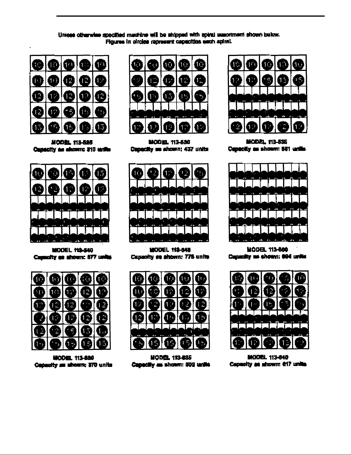
capacities
1
Page 6

capacities
2
Page 7

unpacking
The Snackshop 113 is assembled and packed so that a minimum amount of time is necessary for preparation to install it on
location. The following steps are recommended to insure correct unpacking.
1. Shipping Damage: Thoroughly inspect the exterior of the
carton for damage which may have occurred during shipment. Report any damage to delivering carrier and follow
their instructions.
NOTE: Machines with refrigeration units delivered on
their sides should be stood upright for 24 hours before
the machine is plugged into an outlet.
2. Remove staples from lower edge and those at top of carton,
and slit carton vertically at the taped corner. Open and
remove carton. Remove the remainder of the packing material. On machines shipped with lock in place, the keys are
located in the coin return cup.
3. Remove Vendor With A Fork Lift Truck: Remove the car-
ton from the vendor. Open the door on the vendor and
remove the hold down bracket at the front center of the cabinet base and lose the vendor door. From the front of the
vendor tip the vendor backward and run forks under the cabinet.
4. Removing Vendor Without A Fork Lift Truck: Remove the
carton from the vendor. Remove 1/4 “ piece of plywood
located just behind the front legs, then open the door on the
vendor and remove the hold down bracket at the front center
of the cabinet base and close vendor door. From the front of
the vendor tip the vendor back far enough to clear the wood
strip across the front of the base.Slide vendor toward the back
until the back legs are off the base and pull base out.
NOTE: Because the weight concentration is toward the
back of the cabinet trucking and lifting should be done
from the back. CAUTION should be taken when trucking
from side.
5. On machines with lock in place, unlock, and turn handle to
open door.When no lock is furnished, remove tape and turn
handle.Swing door it its full open position.
6. Remove all packing tape and paper from various areas of
machine and the shipping strap.
7.Warranty: The warranty card is attached to the cover of
this manual. It must be filled out in full and mailed at
once to insure coverage.
8. IMPORTANT: A set of anchoring brackets are sent with
each machine. The kit is located in the bottom of the
machine complete with instructions. It is recommended that
this kit be installed to prevent shifting of the machine.
Kit, Part #660438
installation
1. GENERAL: In some locations, due to the size of this
machine it is not possible to move the fully assembled
machine through doors or narrow hallways. For such locations the door of this vendor can be removed, thus reducing
the clearance required down to 32 inches.
DOOR REMOVAL: To remove the door, swing door to 90
degrees.Remove bolt and washer on door end of door stop.
Unplug the light harness from the main interlock box. The
upper hinge is secured to the cabinet by one bolt extending
through the hinge from the inside of the cabinet.Remove the
bolt with a 1/2 socket. Pull the door forward, the top hinge
plate will slide out of its guide, freeing the door.Lift the door
off of the lower hinge. Remove the left side panel extension
which is held on by six screws. Remove the cabinet to door
filler assembly which is held on by twelve screws. To install
the door, reverse the above procedure.
2. LEVELING THE MACHINE on location is important for the
proper function of the machine. The four leveling screws in
the legs are the means of leveling the machine. After positioning the machine, level machine in front to rear and right
to left directions.After leveling, turn front right (lock side) leveling screw in about one-half turn to drop this corner slightly to make the door easier to close and lock.
3.VOLTAGE AND POLARITY CHECK.It is important that this
machine is hooked up to the proper voltage and polarity.
Using a voltmeter, perform the following checks from the
illustration below.
A. C. HOT (B)
(A) to (B) = 117 VAC (+-10%)
(C)
(B)
(A) to (C) = Less than 1 VAC
(B) to (C) = 117 VAC (+-10%)
A. C. NEUT (A)
EARTH (C)
GROUND
(A)
NOTE: Should the readings be different from above,
have a certified electrician correct the problem.
3
Page 8
installation
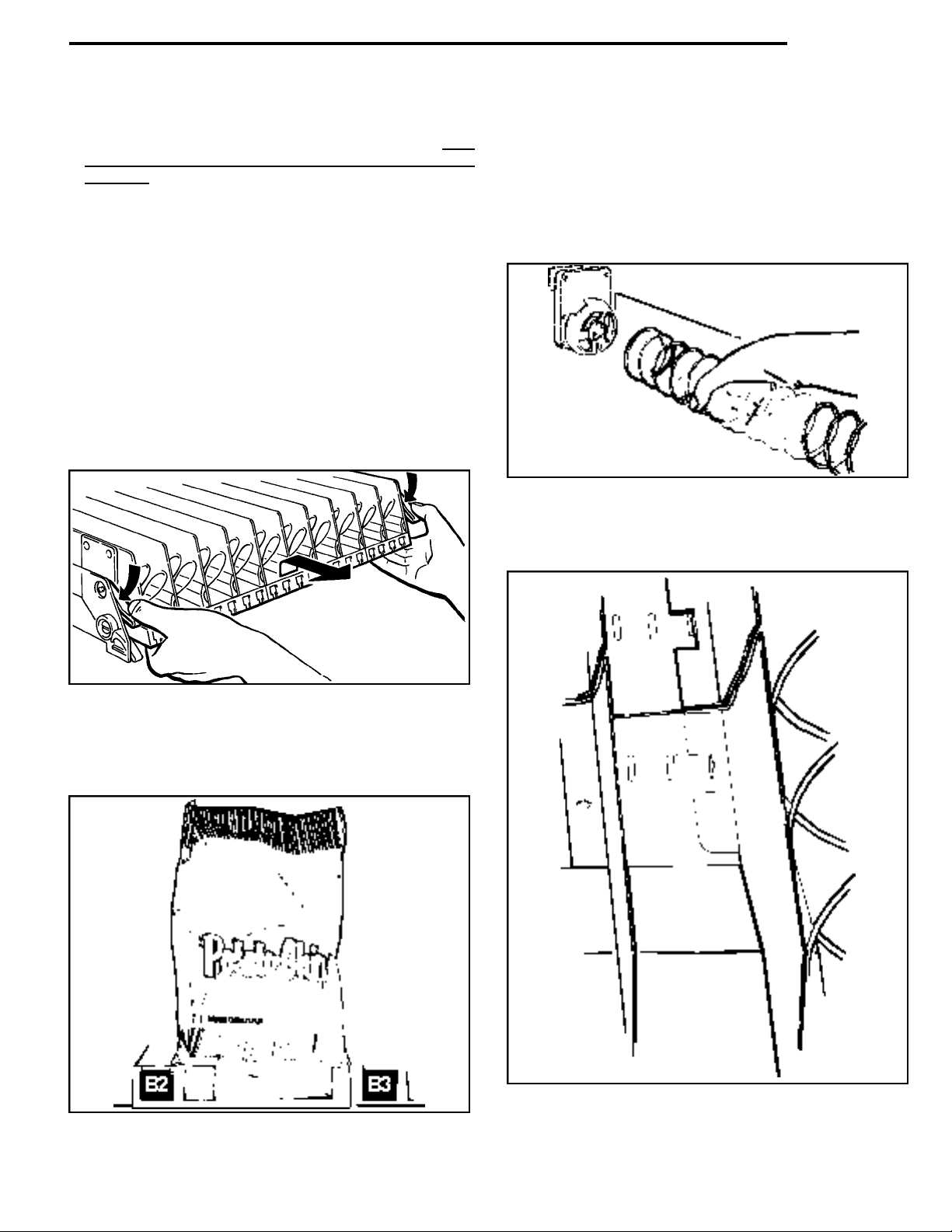
4. L OADING SNACK SHELV E S : Open door to full open
position, push down on white plastic lock lever (Figure 1)to
unlock shelf, holding both levers down. Grasp the shelf
slightly and pull fo r ward until shelf reaches its stop. The
shelves tilt down (do not drop) to make loading easier. O n ly
one product shelf should be in the loading position
at a time. When returning a shelf, be sure the shelf is in its
full home or vend position. Begin loading with the top shelf.
Move it to the loading position.The height spacing for items
is greatest in this shelf and the tallest bagged items should be
placed there.Soft items, such as pastry, pies, etc., should be
placed in the lowest snack shelf, making the drop distance as
short as possible.
IMPORTANT: Product must not be forced into the spiral
spaces but should fit freely. If the product is too tight, use a
larger pitch spiral. The bottom of the product should be
placed on top of the spiral wire that rests on the the shelf
surface (see Figure 2). The width of the product must be
greater than the diameter of the snack spiral. If it is smaller,
the product may fall through when it is in the front, ready to
vend position.
5. REMOVAL OF SPIRAL: Grasp the front of the spiral and turn it
clockwise.Lift the spiral up and off of the spiral lock.When replacing a spiral attach it around the tab on the spiral lock and turn the
spiral counterclockwise to lock it in place.Be sure the front end of
the spiral is positioned properly (with the front end of the spiral
pointing downward on the left side) (see Figure 3).The spiral lock
is attached between the spiral retainer tabs. Give a light forward
pull on front of the spiral to check it it is locked in place.
Figure 3. REMOVING AND
INSTALLING SPIRAL.
Figure 1. MOVING SHELF TO LOADING
POSITION.
Figure 2. PLACEMENT OF PRODUCT ON MAIN
PRODUCT SNACK SHELVES AND
FRONT END POSITION OF SPIRAL.
Figure 4. ALIGNMENT OF MOVEABLE
PRODUCT SPACERS.
4
Page 9
installation
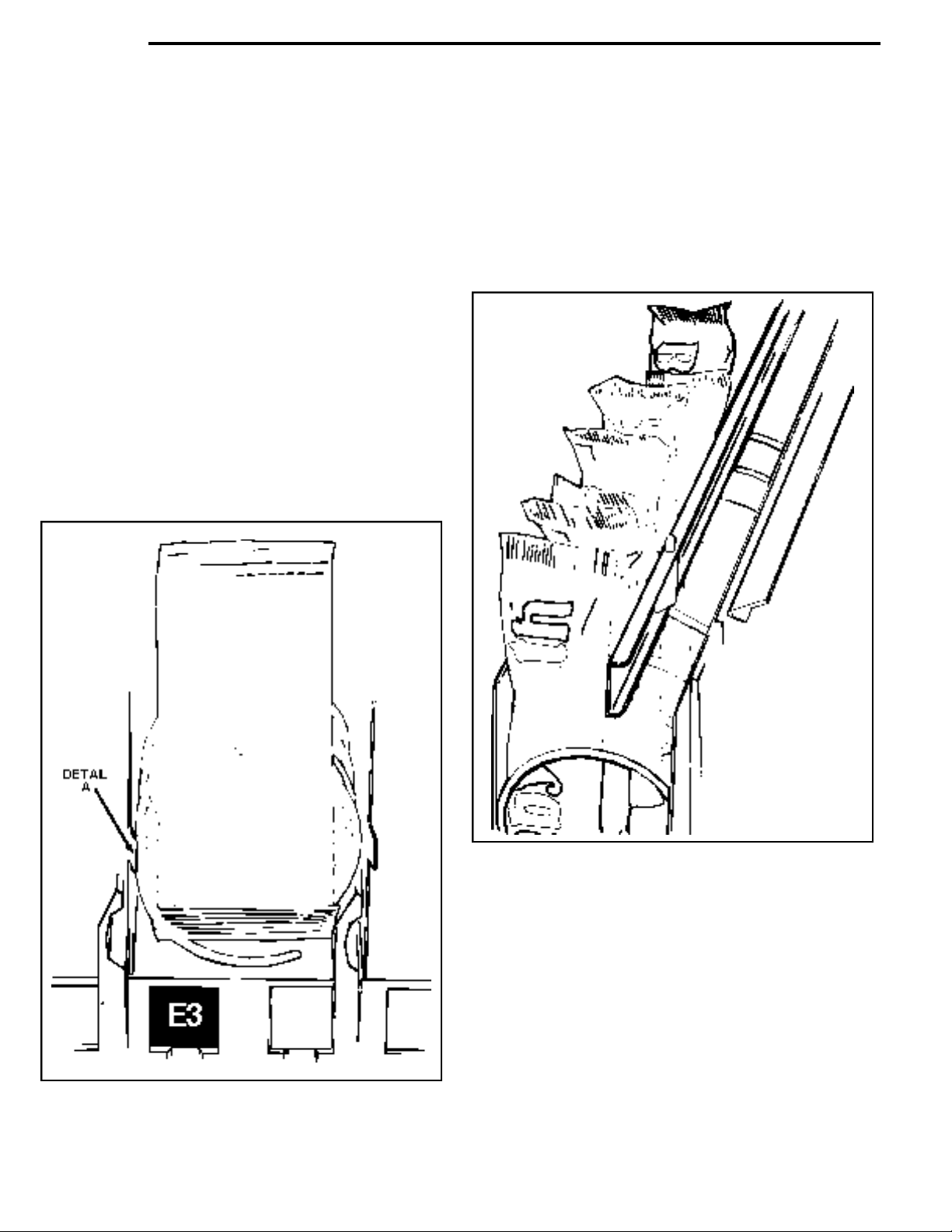
6. PRODUCT SPACERS—5 SELECTION SHELF: A product spacer is used to reduce the width of the product area and should be
used on any 5-selection snack shelf where the product width is
41/2'' or less. Spacers should fit within 1/8” of the product but
should not fit tight against the product.There are three positions
in each snack space where these spacers can be placed. To
install the spacer, align the lock ears (on the lower edge of the
spacer) with one of the three sets of slots (one front and one
rear).(See Figure 4).Push the spacer to the rear to allow the ears
to enter the slots, then allow the spacer to move forward.Be sure
the ears are in the same set of slots, front and rear.(See Figure
4).Continue loading all spirals adjust with spacers where needed
in the top shelf. Return the top shelf to the vend position and following this procedure load the remainder of the large spiral
shelves.The shelf divider separating the right (lock side) column
from the next column is movable to allow vending of products
wider than 5 1/2” in the second column. If this is used the right
column must be used to vend a narrower product.
7. LOADING MAIN PRODUCT CANDY SHELVES:The 10-selection
(candy type) shelves are loaded similar to the 5-selection shelves
except that the bottom of the product sits on the shelf in front of
the spiral wire (see Figure 5) that rests on the shelf.These products must also fit properly product in the spiral space;do not force
product into spiral.
8. PRODUCT SPACERS—10 SELECTION SHELF:The 10 -selec-
These spirals are removed and installed the same as the large
spiral (see Figure 3), except that the front end position is different
(approximately 5 o’clock) (see Figure 5) and the front left side of
the spiral must be behind the small tab located on the left side of
the product space side wall (see Figure 5, Detail A).
tion shelves are equipped with a product spacer (see Figure 6)
that can be pivoted from the right side of each product space.
These spacers should be pivoted out to hold the product upright,
but not tight against the product. Leave about 1/8” clearance
between the spacer and the product.
Figure 6. 10 SELECTION SHELF PRODUCT SPACER
POSITIONED TO HOLD CANDY UPRIGHT.
9. PRODUCT PUSHER:The machine contains enough pushers for
you to install a pusher on each candy spiral.This plastic part is
designed to push the top of the product forward while it is vending, helping it fall from the shelf. It can also be used with products
that have the wrapper end flap on the outside of the package. In
this case, the pusher prevents these products from hanging on
the spiral by spreading the flap. The pusher is installed approximately 210 degrees from the front end of the spiral with the tab
extending forward (see Figure 7).Locate the pusher in its proper
position, hold it against the spiral wire and push the semi-circular
part around the spiral wire. Note: Not every selection spiral will
Figure 5. PLACEMENT OF PRODUCT ON MAIN
PRODUCT CANDY SHELVES AND
FRONT END POSITION OF SPIRAL.
5
need a product Pusher. (Example—Box Items)
Page 10

Figure 7. LOCATION OF PRODUCT PUSHER
ON SPIRAL.
installation
10. BAGGED OR BOXED ITEMS in the 10-selection shelves
if not loaded properly could be a problem. The sealed
edge of the bag may get under the spiral wire causing the
product to hang up after it has been vended. It is recommended that the lower edge of these types of product be
folded forward and up (see Figure 8) next to the product
before inserting into the spiral space. It is also recommended to use an 18 count spiral for bagged items
because of the product settling to the bottom of the package.
11. CIGARETTE VENDING FROM SNACKSHOP 113:
Cigarettes can be vended from the candy shelves using the
(15 capacity) spiral for the soft pack regular, king, 100mm or 120
mm packs. The (12 capacity) spiral should be used for (box)
packs.
12. LOCK PRODUCT SHELVES. After all the product has been
loaded be sure all shelves are returned to their vend position
behind the front roller guide.
13. INSTALL PROPER PRICE TABS into price tab holder for each
selection in the main product area.(See Figure 9.)
14. LOADING GUM AND MINT.The Gum and Mint shelf is located
below the Snack Shelves (optional). Unlatch the shelf by pulling
forward the two metal latches located to the right and left of the
shelf and pull forward.The cover can be pushed back to the rear
for easy loading.The shelf contains four individual selections.
The first selection on the left contains two fillers for use with thin
mints. (Rolaids - Certs, etc.). These fillers can be removed for
standard gum or mints.
Figure 8. FOLD BAGGED ITEMS BOTTOM
EDGE FORWARD AND UP.
Figure 9. INSTALLING
PRICE TABS
The two selections on the right of the Gum and Mint shelf also
have fillers. These selections can be used for standard size gum
and mints or the fillers may be removed for larger gum and mint
products.
Each selection has a display hinge assembly which should be
adjusted after the shelf is loaded. To adjust the display hinge,
loosen the wing nut and slide the spring hinge of the flipper over
the second product and fasten tightly.
6
Page 11

components
1.POWER SUPPLY
The 115 volt power cord from the wall outlet comes into the
machine and plugs into the bottom of the main junction box located to the right of the swing out panel. The other connections on
the main junction box are for the light, fan (optional), 115 volt plug
for bill validator and changer plug.The 115 VAC goes to the on &
off switch and then to the circuit breaker .The 115 VAC goes to the
transformer in which the voltage outputs (total of five) then goes
to the P1 location on the control board.
2.CHANGERS
The Snackshop 113 can use a variety of either Mars or Coinco
changers.The machine is wired for either 24 volt or 115 volt models. When using a 24 volt 12 pin changer either (Coinco 9302L)
or Mars (TRC-6010) an adapter harness MUST be used and
inserted into the main junction box.The Coinco (9302LF) & Mars
(TRC-6010XV) are 15 pin, 24 volt chargers which do not need an
adapter harness. The 115 volt models available are the Mars
(TRC-6000), (MC-5000), and Coinco (9300L).
When installing the changer or removing the changer from the
machine be sure to turn the power off. The changer is to be
mounted on the three studs provided on the swing out bracket &
fastened down.(Refer to the changer manufacturer on the installation and operation guide of the changer.) Load the changer payout tubes with coins and turn your power switch on.
Limit Coin Payout-Service Code 0130
Under certain conditions, a high vend price (greater than $10.00)
may cause the level of coins available for change payback in the
coin mechanism to be repeatedly depleted and prevent further
sales. If this situation exists, then you have the option to limit the
amount of change that is returned to $3.00 or if the amount of
change to be returned exceeds $3.00, permit the vend but return
no change.This option is controlled as follows:
1. Press mode switch 1 time to access service mode.
2. Press 0130, display will now sho w“NO CHG Y/N”with either
the Y or the N flashing.When the Y is flashing the amount of
change to be paid is limited to $3.00.When the N is flashing,
the machine operates normally and returns the full amount
of change required. Option is normally set with the N flashing from the factory.
3. Use any letter but K to toggle the Y/N back and forth to the
required setting.
4. Press K to return to service and lock in the change.
CODE 133
Allows the user to turn tube leveling on or off. Once the code is
entered, the display will show “TUBE_L Y/N”with the cursor at “Y”
(tube leveling: the coin tube that has the highest height in coins
is paid out first) or “N”(normal change payout:change will be paid
out with the least number of coins).Press button “10”to alternate
between the choices.Pressing the “K” button will lock in the information and return the user to the Service mode.
(NOTE: This code will not work with executive mechs.)
3.COIN MECH INVENTORY
This function allows the monitoring and adjustment of the coin
levels in the tubes of the coin mechanism, as long as all coins
have entered the coin mech through the coin entry chute and not
through the tube slots, the display will show a current and accurate inventory of monies in the coin mech.
From the “service” mode, press #10, #1, #2, #5 the display will
show “INV XX.XX” which represents the coin mechanism inventory. Deposit some coins through the coin entry chute to increase
the inventory. Pressing the normal payout buttons, #1, 2, 3 or 4
will decrease the inventory.When or if the power to the machine
is turned off, the information is retained so that the coin mechanism and bill validator continue to operate properly.The scrolling
display will reflect the current inventory as coins are added or
subtracted.Entering 012C from service will reset the inventory to
$0.00 and reenter the mode to allow a new inventory to be established.
4.MODE SWITCH
The Snackshop 113 has only one mode switch that allows control of the machine functions. It is located on the control board.
This switch will allow three modes of operation – operate (normal
mode), control & service mode, and price setting mode.
5.OPERATE MODE
The operate mode is the normal vending position. This position
allows three functions:
A. Pressing a selection will display the price of that selection.If
any selection is not operating or not programmed in the
machine a beep will sound and the display will read “Make
another selection”.
B. Insertion of coins will display “Credit” and the amount.
C. Customer instructions will appear on the display “Make
another selection”, “Use correct change”, or “Check selec-
tion price” for those three conditions which might occur.
NOTE: If in any of the other modes of operation the mode switch
or coin return has to be depressed to get back into the operate
mode.
6.CONTROL-SERVICE MODE
The mode switch on the control board should be pressed once to
enter the control-service mode.Upon pressing the switch all nonoperating selections will be displayed.Next, continue to press the
letter “K” to advance any other problem with a failed motor until
you reach “Service”. Entering into the service mode use of the
selection buttons (1-10) is necessary for the following functions.
Press #1 – Dispenses 5¢ from the changer.
Press #2 – Dispenses 10¢ from the changer.
Press #3 – Dispenses 25¢ from the changer.
Press #4 – Dispenses $1.00 from the changer.
Press #5 – Displays escrow y/n.
(NOTE: y/n use is for yes or no.Pressing #5 changes the position
of the flashing letter. This display indicates which way the bill will
be taken.)
Press #5 – Escrow y/n.In the “yes”mode the bill will be escrowed
so if you push the coin return button you will get that bill back. If
a selection is priced over a dollar (Example: A1 is $1.25) the bill
validator will not take a second dollar.You must use a dollar and
insert change.In the “no”mode the bill will not be escrowed (goes
directly into the stacker) so if you push the coin return you will get
back change.
(NOTE: The coin mechanism must contain enough coins in all
three coin tubes for this
Press #6 – Displays force y/n. (NOTE:y/n use is for yes or no.
Pressing #6 changes the position of the flashing letter.) Pressing
#6 in the “yes” mode when pricing in the machine is above a dollar, the bill will be taken and you must buy a selection.In the “no”
mode allows you to make a selection or if you change your mind
push the coin return button to get your money back.
Press #7 – Displays multi y/n. (NOTE: y/n use is for yes or no.
Pressing #7 changes the position of the flashing letter.) When
multi vend is in the “yes” mode after a dollar bill or change is
inserted, will register the amount on the digital display. When a
function.)
7
Page 12

components
selection is made the amount on the digital display will deduct the
price of that selection.At this time the total cash will be displayed
of the amount left of that dollar so that another selection may be
made without inserting more money.You, therefore, can push the
coin return for your change or make as many selections you want
to until the digital display reads below the lowest selling price in
the machine, then the rest of the money will be paid automatically. (NOTE: When using the shoppers mode, there is also a delay
time incorporated on the control board. If a customer does not
make another selection after a period of 10-15 seconds the
changer will pay back automatically.)
Press #8 – The display will show cash 000 (total cash sales).
Pressing #8 again gives the amount of vends 000 (total vends).
Pressing #8 will show (total bills) 000 accepted. Pressing #8 will
show the amount of times the machine has been reset.
Press #9 – Displays free vend y/n. (NOTE: y/n use is for yes or
no. Pressing #9 changes the position of the flashing letter).When
using the “yes” mode push the coin return button and you can
now free vend or test each motor.(NOTE: Test vend will not add
money or vends to cash sales or total vends.) Closing the door
removes the test mode to the “no” mode automatically.
Press #10 – The display will appear blank. This will allow you
to program from 100 mode through 900 mode in the machine.
(NOTE: When programming into different modes, the #10 button
will be 0.) Re-entry from one mode back to the blank display can
be accomplished by pressing “K”(which puts you back in service)
then pressing #10 (blank display) and programming another
mode. From the Service Mode - press #10 (blank display.)
100 MODE – Winner mode. Press #1-#10-#10 which is the winner mode. This function enables you to program the machine to
give “free” products every so many cash vends. Setting this program at 001 will set the machine on free vend. (Every vend will
give you that product and then return the money.) Setting on 012
will give a “FREE” product every twelve vends. “ FREE” products
can be set from 001 to the maximum range of 255 vends.(NOTE:
Pressing the letter “K” will return you to the start of the service
mode.)
200 MODE – Clock mode. From the service mode, press #10
(blank display). Press #2-#10#10 which is in the clock mode.
This function enables you to set or change a clock.(Used for discounts and machine shut down time.) After pressing 200, the digital display will show 00 which represents the last two numbers of
the year.Press the numbers for the present year. Press the letter
“J” and 00 will appear which represents the month. Press 01 to
12 for the month.Press “J” again and 00 will reappear for the day.
Press the numbers 01 to 31 for the day. Press “J” and 00 will be
displayed for the hour. Set the hour from 00 thru 23; Midnight
being 00 to 01 a.m. Press “J” and 00 will reappear for minutes.
Use 00 to 59 for the current minute. Lock the clock times in by
pressing “J”. (NOTE: Pressing the letter “K” will return you to the
start of the service mode.)
300 MODE – Identification mode.From the service mode-Press
#10 (blank display).Press #3-#10#10 which is the identification
mode. This function enables you to set a machine identification
number.The display will show 8 zeros and by pressing any combination of numbers (maximum of 8 numbers) you can enter a
machine identification number.(NOTE: This identification number
will appear in the sales data mode 500.) (NOTE: Pressing the let-
ter “K” will return you to the start of the service mode.)
400 MODE – Message mode. From the service mode-Press #10
(blank display). Press #4-#10#10 which is the message pro-
gram.This function enables you to change the scrolling message
“Have A Nice Day” to any message you want to program.
Alternative languages are also available by pressing:
English #4 #10 #1 French #4 #10 #6
German #4 #10 #2 Danish #4 #10 #7
Spanish #4 #10 #3 Swedish #4 #10 #8
Italian #4 #10 #4 Russian #4 #10 #9
Dutch #4 #10 #5 Slovenia #4 #10 #10
Entering into the message program (any language) one of the letters will be flashing. The flashing letter is the character to be
changed.The character may be moved to the right by pressing #1
or to the left by pressing #2. When the character you want
changed is flashing use the letter “A”to change it. Passing up the
character (letter or symbol) you can reverse the scrolling direction
by pressing the letter “B”.Complete your message by moving and
changing each character. Pressing the letter “C” you can insert a
new letter. Pressing the letter “D” will delete the flashing character
and move the whole message to the right (out of view) which
delays the scroll from coming on the display.Your message can
be programmed up to 137 characters. (NOTE: To eliminate
programmed message in any language and have the original
A Nice Day” appear you just program (401-408).When not using
the message display as an option, the display can display the
exact time (set in the clock mode - 200). Displaying the time can
be achieved by moving the flashing character to the far left
button #2 and entering the “ ” character with button “A”. (NOTE: the
“ ” character can be used to delete all or part of the message.)
the message program (close door, push operate button,
coin return, or push the button “K”to return to “Service”mode).
500 MODE – Sales data mode. From the Service mode, press
#10 (blank display). Press #5-#10#10 which is the display sales
data mode.The machine identification number, if programmed in
the (#300) mode, will appear.(NOTE: The display sales data can
be retrieved only when using the product codes.See price setting
mode.) Press button #1 and the first product code will be displayed with the number of vends of that product code .Press number #1 for the next product code and sales data.Continue pressing #1 until you reach the machine identification number. Press
“K” to return to the “Service” Mode.
501 MODE – MIS Print – Allows you to print to a hand held printer the information on page 46 by using the following procedure.
A.POWER DOWN MACHINE
B. CONNECT HARNESS PART#680509 TO P10 TERMI-
NAL ON BOARD AND THE 25 PIN RS 232 END TO
PRINTER.
C.POWER UP MACHINE
D. ENTER SERVICE MODE
E.PRESS 10 DISPLAY (DISPLAYWILL GO BLANK)
F. PRESS 5-0-1 TO INITIATE PRINTOUT MODE
G.DISPLAYWILL SHOW MIS PRINT AND THE PRINTER
WILL START.
H. IT WILL AUTOMATICALL Y TERMINATE AT THE END
OF THE DATA TRANSMISSION, AND RETURNS TO
THE SERVICE MODE.(A SERIES OF THREE BEEPS
ARE PRODUCED, SIGNIFYING THE END OF DATA
TRANSMISSION.
600 MODE – Reset sales data mode. From the Service ModePress #10 (blank display).CAUTION:Press #6-#-10-#10 which is
the reset sales data mode, resets all vends programmed with
product codes retrieved in the 500 mode.
700 MODE – Bill Value Set Up: From the Service Mode, press
#10 (blank display). Press #7-#10-#10 which is the 700 mode.
Display will show “B VALXXXX”once this code has been entered.
You can enter a 4 digit number representing the value of the bill.
your
“Have
with
Exit
depress
8
Page 13

components
components
(Example: for U.S.Dollars, the value is 100.) Note that the credit
is incremented by the entered value for each pulse coming from
the bill acceptor.When the XRAM is initialized, the bill value is set
to 100.When a TRC mech is connected to the controller, the controller ignores the bill value entered and uses 100 (note that it
ignores, not alters, the entered value).
800 MODE - Whole Machine Discount: This function allows you
to discount the selling of merchandise for the entire machine at a
percent and up to three time periods per day (A, B. C,) and up to
seven days of the week. (NOTE: The time must be programmed
in the 200 mode for this feature.)
Step #1 – From the Service Mode, press #10 (blank display).
Press #8-#10-#10 which is the 800 mode (machine or selection
discount mode). The “STRT” will appear (this will automatically
put you in time period “A”).Enter the time when you want the discount of the entire machine to start.The start time is set on a 24
hour (military) basis starting with 00:00 as midnight (Example:
1:00 p.m. as 1300 hours).
Step #2 – Press the “G” button once and “STOP” will appear.
Enter the stop time (NOTE: The “STOP” time is set for the
machine to go back to full price of the products).
Step #3 – Press the “H”button and “PRCT”will appear. Select the
(%) percent of discount desired using the number buttons to
enter the discount for the “Whole Machine”.(Setting at 100% the
products will sell for free.) (NOTE:Clearing or cancelling all of the
3 steps can be done by pressing the “J” button.)
Step #4 – If a discount is only desired on certain days of the
week, it can be programmed by pressing the “F” button. Pressing
“F”the display will show DY0000000.This represents each day of
the week “Sunday through Saturday” from right to left.
Display Shows:
“0” meaning “OFF”
“1” meaning “ON”
Pressing button “1” or button “10”-”0” will set each “day” on or off
for discounting.
Example: Shows Monday, Wednesday and Friday - machine will
be on discount for time period “A”.
Display Shows:
Step #5 – Press button “K”to return to the service mode and lock
in the “A” discount time period.Setting up for more than one dis count time period by using buttons B. C, and D. Example: After
setting the time period “A” with the four programming steps, press
the letter “B” to enter its time period and repeat the four steps in
programming the discount time period, the display will read “Buy
Now and Save X%” at the different times.
800 MODE - Discount by Selection: This function allows you to
discount the selling of merchandise by selection at a discount
price. Prices can be set up to four time periods per day (A, B. C
& D) and up to seven days of the week.
Step #1 – From the service mode, press #10 (blank display).
Press #8-#10-#10 which is the 800 mode (selection discount
mode).The “STRT” will appear (this will automatically put you in
time period “A”). Enter the time when you want the discounted
price per selection to occur. The start time is set on a 24 hour
(military) basis starting with 00:00 as midnight (Example: 1:00
p.m.as 1300 hours).
Step #2 – Press the “G” button once and “STOP” will appear.
Enter the stop time for the discounted prices. (NOTE: The stop
time is then set to put the machine back to the original prices.)
Step #3 – Press the “H”button and “PRCT”will appear. Enter buttons #1-#10-#1.(101)
Step #4 – If a discount is only desired on certain days of the
week, it can be programmed by pressing the “F”button. Pressing
“F”the display will show DY0000000.This represents each day of
the week “Sunday through Saturday” from right to left.
Display Shows:
“0” meaning “OFF”
“1” meaning “ON”
Pressing button “1” or button “10”-”0” will set each “day” on or off
for discounting.
Example: Shows Monday, Wednesday and Friday - machine will
be on discount for time period “A”.
Display Shows:
“0” meaning “OFF”
“1” meaning “ON”
Step #5 – Press mode switch once (control board) to access
price set mode.The display will show “PR”.
Step #6 – Press the “K”button which will access the product code
setting. Press #9-#9-#9 the display will show “PRD1 00.00”.This
is where all “Cash” discounts are set for time period “A”.
Step #7 – Enter the cash discount desired (Example: 00.05,
00.10, etc.) Using letter and number combinations, you can program the discount per selections similar to set pricing.When the
discount is programmed in the selling price of a selection it will be
equal to the original price minus the cash discount.You can have
more than one cash discount amount in a single time period by
repeating step #7.
Step #8 – Setting extra time periods with discounts on selections
by using Steps #1 through #7.When in step #1 pressing #8-#10#10 which is the 800 mode use button “B” for PRD2, button “C”
for PRD3, and button “D”for PRD4.When the discount time periods occur, the display will show “Buy Selection A1 for 00.XX”,
“Buy Selection B7 for 00.XX” “Have A Nice Day”. All discounted
selections will be displayed followed by the normal user message
and then repeated.
Clearing Discount by Selection: IMPORTANT: Clearing dis-
counts on individual selections is a two step procedure. Both
steps, if not programmed, will leave previous discounted selections with any discounted selections being set in the program.
Step #1 – Press mode switch once (control board) to access the
service mode.Press #10-#8-#10-#10 (0800) the display will show
“START XX:XX” time period “A”. Clearing the time period “A” of
discounts by pressing the letter “J”, the display will be blank.
Clearing other time discounts by pressing “B” time period and
pressing the letter “J”, same on “C” and “D” time periods. After
9
Page 14

components
clearing the time periods, press “K”to return to the service mode
and lock in the information.
Step #2 – Press mode switch once (control board) to access the
price set mode.The display will show “PR”. Press the button “K”
which will access you into the product code setting. Press button
#9-#9#9 which will display “PRD1 00.00. This is where all cash
discounts are set for period “A”.Press button “J” to clear the cash
discounts for time period “A”.Press button “K” to advance to time
period “B” which will show “PRD2 00.00” on the display. Press
button “J” to clear time period “B”. Repeat the step for “C” time
period PRD3 and timer period “D” PRD4.
900 MODE – Shut-down mode. From the service mode, press
#10(the display will be blank). Press #9-#10-#10 shut-down
mode. This function enables the machine to be turned off at a
certain time and then be turned back on at a given time. (NOTE:
The machine must be programmed in the 200 mode to use this
feature.) The machine can be programmed to be turned off and
then back on in four different time periods (A, B.C and D) and any
day of the week.
The display will show “STRT”.(This automatically puts you in time
period “A”).Enter the start time by pressing the buttons using the
clock (military) from 00:00 as midnight to 23:00 hours as 11:00
p.m.
(NOTE: The “Start” time is for the shut down time and the “Stop”
time is for resuming time.) Press button “G”, it will display “Stop”
time. Enter the stop time. Press button “F”, the display will show
DY0000000. This simulates days of the week Sunday through
Saturday (right to left).Use button #1 for on and #10 as 0 for off.
“0” meaning “OFF”
“1” meaning “ON”
Example: Shows Monday, Wednesday, Friday machine will shut
down. For START and STOP time, set in “A” period.
Display Shows:
“0” meaning “OFF”
“1” meaning “ON”
Setting more than one time period by using buttons “B”, “C” and
“D”, Example: After setting time period “A”, press button “B”.
Press button “G”, the display will show “STRT”.Enter the time for
period “B”. Press button “G”, the display will show “STOP”. Enter
the stop time for period “B”.Press button “F”, the display will show
DY0000000. Set days you want period “ B” to shut down the
machine. (See chart, above). Continue if needed for periods C &
D by using the same procedure. During the shut down time, the
display will scroll “Machine Use Not Allowed until XXXX.” Service
functions are allowed during the shut down times.
Previous machines had to be programmed to start and stop on
the same day. A software change on the control board makes it
possible now to start on one day and to stop on the next day.This
feature may be used in both the 800 (discount) or 900 (shut
down) mode.The day of the stop time does not need to be specified by using the “ F”‘ button .The board will automatically stop
the 800 or 900 feature the day after it is started.
Example: Periods of discount or shutdown Monday 10:00 p. m .
to Tuesday 2:00 a.m.,Thursday 10:00 p.m. to Friday 2:00 p.m.
7.PRICE SET MODE
8.PRICE CHECK MODE
Display Shows:
“0” meaning “OFF”
“1” meaning “ON”
Two for One Option Mode – This function will allow you to vend
two products for the price of one.From the service mode – Press
#10 (blank display). Press #1-#1-#10, the “_ _->_ _” will appear
on the display. Select the purchased selection letter (A-G) then
the number (1-10).The display will then show your selection letter (A-G) then the number (1-10).The display will then show your
selection on the display (Example:“B3->_ _”) Now select the free
selection letter and number. The display will then be (Example:
“B3 - B5”). The two for one option is available for six combinations.After setting the first combination, press button “J”to set the
next combination. NOTE: Programming the same selection on
both sides of the arrowhead (Example: B2 - B2) the selection will
run twice.
Clearing 2 for 1 Option – From the service mode, press button
10 (blank display) Press #1-#1-#C,this will clear all combinations
for this option.The display will show “_ _->_ _” to allow re-entering of new combinations or press button “K” to return to service.
EXITING SERVICE MODE
1. Press the mode switch on the board twice.
2. Deposit Money
3. Close the Door.
4. Push Coin Return.
5. Wait 5 Seconds.
The mode switch on the control board should be pressed twice to
enter into the price set mode or once from the service mode.The
display will then show (.) a decimal point.To set prices push the
numbers (1-10) needed to change the display (Example 7 & 5 will
display .75) Pressing the letter and then number (A-1) you will get
two beeps indicating that selection price is set. To cancel the
price display push letter “J”.
To set prices with a product code which are available (00 to 99)
press the letter “K”and push the desired code. Press the letter “J”
and set the price.The product code & price showing on the display can now be entered to the program.Set all selections using
“J” for pricing & “K” for product code. (NOTE: 500 mode is used
to retrieve sales data of the product codes.)
This mode allows you to check prices and products codes set on
each selection. Entering into the price check mode can be done
by pressing the mode switch on the control board three times
from operate (stand-by) or once from the prices set mode.Check
each selection by pressing the letter and then the number.
(NOTE:You can re-enter the service mode by pressing button “K”
from the price check mode.This function saves time by not having to wait for the motor home check and the shelf check and
“*********”.
Discount Time Periods
Checking prices of an item in one of the four discount time periods may be accomplished by pressing the mode switch (control
board) two times to access the price set mode. Press the letter
“K”. Press #9-#9-#9. The display will show “PRD1 00.00”. Press
the mode switch (control board) once to access price check
mode.The display will show“CK”.Press button “J”the display will
show “CK D1”.Any selection that has a cash discount set in time
period A will show the discounted price when that letter/number
10
Page 15

components
combination (i.e.A3, F3).Press J will step to CK D 2 for time period B etc.If no discount has been set, then the normal vend price
will be displayed.
9.SELECTION PANEL
The selection panel (see figure 10) on the Snackshop 113 incorporates that use of a self enclosed membrane switch panel.This
eliminates the need for individual switches and wiring.The membrane switch panel is housed in a stainless steel panel with individual buttons protecting the switch face. The casting front also
houses the display lens.The display lens gives instructions to the
customer for three conditions which might occur (make another
selection, use correct change, or check selection price).The display lens also can carry any message which can be programmed.
For example “Have a good day.”
10.VEND MOTORS
The Snackshop 113 incorporates the use of a high RPM DC
motor. Due to the new design, the vend motor may no longer be
homed by hand. DO NOT TRY TO TURN THE SPIRALS BY
HAND. DAMAGE TO THE MOTOR WILL RESULT. It is also
important to check polarity before applying current to the motor.
Two diodes and a capacitor are used to prevent circuit feedback
and may have to be checked when trouble shooting motor problems.
11.LIGHTING SYSTEM:
There is only one fluorescent lamp in the Snackshop 113. The
lamp is located on the top inside of the door which lights up the
main product area.The starter is located on the hinge side of the
lamp.The ballast and line filter is located on the top front left shelf
support. (page 17, item 18)
12.MAIN PRODUCT SHELVES:
There are five or six main product shelves per machine. Each
containing either five or ten selections.Each selection has its own
motor mounted to the back of the shelf. Every shelf has its own
harness and plug for connecting to the remainder of the circuit
through the cabinet receptacle, located in the rear right of the
cabinet.The motors are the same on either type shelf. It is now
possible in the Snackshop 113 to exchange a five selection shelf
with a ten selection shelf or visa versa.You also have the capability to gain 1/2 inch either up or down on any shelf. To do this
the shelf should be removed and the cabinet back harness receptacle lowered or raised with the right & left shelf tracks.
NOTE: When exchanging the shelves, you will not need any
parts, but you will have to reprogram the machines for prices and
selections.
REMOVAL OF PRODUCT SHELF:
A. Lift up and push the lock levers toward the back of cabinet.
See figure 1, page 4.
B. Pull the shelf to its loading position.
C. Grasp shelf in front and rear center. Lift front of shelf up
above horizontal and pull shelf forward while lifting.
D. To install shelf, reverse above procedure.
13.DELIVERY BIN:
This is located below the display window on the door and is
mechanically operated. The linkage on the outside end of the
delivery bin may require occasional lubrication. Should the door
become difficult to operate, place a small amount of grease on
the arm tracks.
REMOVAL OF DELIVERY BIN:
A. Remove the screws from the underside of the delivery bin .
These screws fasten into the lower door brace and remove
the two screws and brackets at the top of the delivery bin.
B. Grasp delivery bin on both sides and lift up and pull back.
Should bin be tight, rock it by lifting on one end, then the
other.
REPLACEMENT OF DELIVERY BIN:
A. Locate lip on front edge of delivery bin over lower edge of
opening in door and behind trim. Press down along lip to
make sure it is fully engaged between door and trim.
B. Install the four screws and two brackets, to secure bin to
door.
14.REMOVAL OF GUM AND MINT MOTOR AND/OR EJECTORS:
Disconnect the two wires going to the motor and remove the four
screws holding it to the shelf. The components attached to the
front base can also be replaced.These consist of the gum and
mint shelf front (Price tabs and selection), gum and mint shelf
front base, gum and mint display front stop (plastic) and the gum
and mint ejector.
NOTE:Before replacing the gum and mint motor it would be helpful to tap the motor first with the screws. Assemble the four components together and mount them to the motor making sure that
the head crank of the motor is inserted into the ejector.Replace
the four screws and test vend that selection for proper operation.
15.REMOVAL OF GUM AND MINT SHELF:
Below the gum and mint shelf remove the two screws holding the
gum and mint receptacle harness bracket (page 19, item 21).
Loosen the other two screws on each end of the gum and mint
pusher stop strap (page 29, item 20) and disengage it from the
cabinet. Grasp the shelf and pull the shelf straight out. With the
shelf out you can replace the gum and mint pusher (page 29,
item 31) by removing the screw (page 29, item 21).
Reverse the procedure to replace the shelf. Pay special attention
when you put the gum and mint pusher stop strap back on that all
the gum and mint pushers have spring tension and are behind
the strap.
11
Page 16

16.CHILLED AIR MACHINE
When placing a chilled machine at a location Caution should be
taken to keep adequate clearance in the rear and front bottom
screens for proper circulation. The front vent screen assembly
(page 37, item 25) should be removed and cleaned periodically
for proper operation of the refrigeration system.
NOTE: The cold control setting (page 37, item 15) should be set
on the #4 position.
The Snackshop 113 will do the best merchandising job for you
if it is kept clean.The display window can be cleaned with any
good glass cleaner. The exterior and interior surfaces should
be cleaned with warm water and mild detergent. Rinse thoroughly and dry all surfaces.
CAUTION:
Do not use any cleaners containing silicon as
this could cause electrical failures.
components
17.REMOVAL OF COOLING UNIT:
Replacing a cooling unit can be done by removing the two screws
from the Air Duct Support Bracket (page 35, item 3).Then, lift the
air duct up and out of the cooling unit.Remove the two screws in
the bottom of the cooling pan located to the right and next to the
blower (page 37, item 23). The cooling unit can now be pulled
straight out from the angle guides. Reverse the procedure to put
the cooling unit back in the machine.
cleaning
The main product shelves can be best cleaned with the spirals
and product spacers removed. Refer to page 4 for removal of
spirals and page 5 for removal of the product spacer.
Clean the acceptor on the changer frequently as accumulated
dirt in this area can cause coins to hang or not be accepted.
Follow recommended cleaning procedures as described by the
manufacturer.
optional equipment
1. VENTILATING FAN: (Part #660441 - 120 Volts)
(Part #660441-1 - 240 Volts) Export
The ventilating fan keeps a steady flow of air moving through the
vendor cabinet.Installation of the fan takes only a few minutes.All
the vendors are wired with a fan plug on the junction box for easy
installation.
2. BASE KITS: (Part # 660146-13)
Base kits are available to make the vendor compatible with other
manufacturers.
3. GUM AND MINT:
Gum and Mint units are available as an option with Snackshop
113 vendors. For information pertaining to loading or servicing
gum and mint unit, refer to this service manual for loading instructions and for service instructions.
4. SPECIAL SPIRALS:
Special candy spirals are available for use in the five (5) selection
snack shelves. For the sake of identification, the back end of
these spirals are colored RED and should never be used in the
ten (10) selection candy shelves.
These spirals allow vending products that are too wide for the
standard candy columns but may be too thin for the regular snack
spirals. A product pusher and spacer should be used where
r e q u i r e d . Pa rt numbers for these special spirals are as
follows:
400139-1 12 space special spiral
400140-1 15 space special spiral
400141-1 18 space special spiral
400142-1 24 space special spiral
400143-1 30 space special spiral
400151-1 20 space special spiral
NOTE:The difference between the standard candy spiral and the
special candy spiral used in the wide snack columns is in the
overall length of the spiral.The special spiral is shorter than the
standard candy spirals.
CAUTION: Do not attempt to use the special candy spirals in an
ten (10) selection shelf.
5. SOUP DISPENSER: (Kit 750083)
A canned soup dispenser is available as an option for use in
the five selection snack shelves.The dispenser is easy to install
and holds up to nine cans in the unit
6. DOLLAR BILL VALIDATORS:
The validators take only a few minutes to install and may be purchased through the manufacturer of that unit.Mars has a 24 volt
& 115 volt Validator available which will work in the machine provided that you use the right harness.The 115 volt harness can be
ordered from Automatic Products under part #680475. The 24
volt harness can be ordered under part #680355. ARDAC validators need a kit supplied FROM ARDAC under part #48X600-4 to
be added to the 113 machine. Coinco validators can also be
used, which are the 115 volt model (BA30SA) or the 24 volt
model (BA32SA).
7. DEBIT CARD READERS:
The 113 series machine will also have the option to add a debit card
r e a d e r.The two choices ava i l a ble are the Mars and Debitek Systems.
8. CHILLED MACHINE:
The 113 machine may be ordered with a refrigeration unit which
allows the inside of the cabinet to be cooled. THE REFRIGERA-
TION UNIT CANNOT BE ADDED TO A MACHINE AT A LATER
DATE.
9. DUAL SPIRAL SHELF:
Snack shelves can be set up to have dual spirals per selection on
the shelf.The dual spirals will help vend specialty items better.
10. CONVERTIBLE SHELF:
The convertible shelf allows you to convert a snack shelf into a
combination candy and snack shelf.The convertible shelf can be
converted from two to ten candy selections. (Example: 4 candy
selections & 3 snack).
11. 114 MASTER:
This unit can slave a 115 machine and is an optional model.The
master machine must be a six shelf machine limited to 30, 35 or
40 selections. The gum and mint unit is optional. The master
machine does not come in Euro-Styling.
12. MIS Printer (Part # 380310)
Printer Harness (Part # 680577)
DEX-UCS Harness (Part # 680509)
All three are needed for printer use (mode 501)
13. DOOR GUARD (Part #750176)
A kit is available to attach the guard to the door to help prevent
someone prying the door open.
12
Page 17

door - outside front
13
Page 18
door – outside front
Item
No. Part No. Description
1 340044-9 Top Trim Vantage.
2 201690-2 Top Trim Insert. True Grit Black.
201690-15 Top Trim Insert. Dark Gray
3 340057-2 Trim Outside Vertical.Black. Right & Left Side.
4 202059-52 Panel, Left Side Vertical.Sterling Royce.
202059-48 Panel, Left Side Vertical.White.
202059-50 Panel, Left Side Vertical.Dove Gray.
202059-8 Panel, Left Side Vertical. Painted.
5 340058-46 Trim Vertical.Window.Black, Right & Left Side.
6 750141 Front Window. (44 5/8 x 26 7/8 x 1/8).
NOTE Replacement Glass Must Be
Hard Tempered or Lexan Only.
7 340058-5 Trim Horizontal.Window. Black.
8 201356-1 Delivery Tray Panel.True Grit Black.
9 640154
10 201678 Bottom Door Edging.
11 420186 Screw Pan Hd.#2 Drill Pt 6-20.
12 201692-1 Lower Horizontal Panel. Black.
201692-56 Lower Horizontal Panel. Dark Gray.
201356-43 Delivery Tray Panel.Dark Gray.
13 440296 Coin Cup Trim. Black.
440296-1 Coin Cup Trim. Dark Brown.
440296-2 Coin Cup Trim.Medium Gray.
201156 Coin Cup Door.
Assembly, Lower Door Hinge Plate. Specify Color.
Item
No. Part No. Description
14 202061-42
202061-38 Panel, Right Side Vertical. Lower.White.
202061-40 Panel, Right Side Vertical. Lower.Dove Gray.
202061-7 Panel, Right Side Vertical. Lower.Painted.
15 420071 Ace Lock W/2 Keys.
420071-1 Ace Lock W/1 Key.
420071-2 Ace Lock W/O Key.
16 660319 Assembly Lock Handle W/Lock Arm & Nut.
420146 Lock Handle Only.
17 660368 Assembly Complete. Selection Panel.
18 600600 Door Only. Specify Color.
600600-1 Door Only. European Style. Specify Color.
600600-2 Door Only.With Validator Hole And Debit Card
19 201678-6 Top Lock Door Edging.
20 202060-50 Panel, Right Side Vertical. Upper.White.
202060-52 Panel, Right Side Vertical. Upper. Dove Gray.
202060-8 Panel, Right Side Vertical. Upper. Painted.
202060-54 P
Panel, Right Side Vertical.Lower. Sterling Royce
See Page #21 for Itemized Parts.
Use. Specify Color.
anel, Right Side Vertical.Upper. Sterling Royce.
14
Page 19

door - inside front
15
Page 20
door – inside front
Item
No. Part No. Description
1 600600 Door Only.Specify Color.
600600-1 Door Only.European Style.Specify Color.
600600-2 Door Only.With Validator Hole And Debit
Card Use. Specify Color
750176
2 660444-1 Bezel Ring . Assembly w/Trim. Black.
660444-2 Bezel Ring.Assembly w/Trim. Brown.
660444-3 Bezel Ring.Assembly w/Trim. Gray.
320060-1 Bezel Ring Only.
3 460499 Bezel Trim. Black.
460499-1 Bezel Trim.Dark Brown.
460499-2 Bezel Trim. Medium Gray.
4 660319 T-Handle & Lock Arm Assembly.
420146 T-Handle Only w/Nut.
5 640131 T-Handle Lock Arm
6 118-10-8 Carriage Bolt #10-24.
7 404-10 Nut, Hex #10-24.
8 276-6R4 Screw Pan HD. Phil. Type 23. #6-32x1/4.
9 400112 Lock Bar Spring.
10 600432-2 Lock Bar Assembly.
11 440296 Coin Cup Trim. Black.
440296-1 Coin Cup Trim. Dark Brown.
440296-2 Coin Cup Trim. Medium Gray.
12 201155 Coin Return Cup
660569
600705 Coin Return Cup only Export
202432 Striker, Door Switch Export
300184 Shoulder Bushing Export
276-8R6 Screw, Pan HD Self Tap (8-32x3/8)(2)
400188 Spring, Striker Door Switch
201894 Coin Cup Filler Plate.
13 18443 Nut 1/4. Self-Threading.
14 460041-1 Door Gasket Foam 1/4 x 1/4.
15 420040-9 Hole Plug.
16 276-8R6 Screw, Pan Hd.Phil. Type 23# 8-32x3/8.
17 750141 Front Window. (44-5/8 x 26-7/8 x 1/8)
460570 Decal.“COOL - COOL”(not shown).
Kit, Door Guard Plate (Not Shown). Specify Color
Assembly Coin Cup & Striker Export (not shown)
NOTE: Replacement Glass Must Be
Hard Tempered or Lexan Only.
Item
No. Part No. Description
18 201384 Bottom Window Clamp.
19 202118 Window Clamp. Lock Side.
20 200906 Bin Anchor Strap.
21 201381-3 Shield & Window Clamp. Pivot Side.
22 201-6R11 Screw RD. HD.Philips Type B #6 x 11/16.
300206 Screw, Window
23 400095 Door Stop.
24 114-41-8 Screw, Hex HD.Cap 1/4 -20 x 1/2.
25 420010-10 Washer 1 1/8 OD.
26 300156 Door Stop Anchor.
27 420010-18 Washer, Brass (Door Adjustment).
28 640154 Lower Door Hinge Plate Assembly.
Specify Color.
29 420003 Flat Head Socket Screw. 3/4 Lg.
30 420003-1 Flat Head Socket Screw.1/2 Lg.
31 217-8R10 Screw.Pan Head, Philips Type B #8 x 5/8.
32 660558 Delivery Bin.Assembly Complete.
See Page 31 For Itemized Parts.
33 460436 Window Edging (Order Per Inches) 143
Total.
34 380022-5 Fluorescent Lamp F18T8/CWK24.
380023-4 Starter FSII 240 volt
35 380023 Starter FS-25.
36 680512 Lamp Harness Assembly.
680456 Light Cord (Not Shown)
37 420062-1 Screw Round Head Slot Mach.#4-36 x 3/4.
38 201156 Coin Cup Door.
39 2016R7 Trim Screws. Screw Rd. Hd.
Phillips Type A (6-18 x 3/8).
2006R6 Trim Screws. Screw Rd. Hd.
Phillips Type A (6-18 x 3/8).
16
Page 21

cabinet
17
Page 22

cabinet
Item
No. Part No. Description
1 750100-4 Cabinet Assembly Complete. With Legs.
Specify Color. (113)
750100-5 Cabinet Assembly Complete With Legs
Specify Color. (114)
2 202119 Filler Plate. Left Front.
3 600310 Assembly, Cabinet to Door Filler.
Specify Color.
4 276-8R6 Screw, Pan Hd.Self Tap. (8-32 x 3/8)
5 202120 Shelf Support. Left Front.
6 640177 Assembly, Cabinet Shelf Track.Left.
7 201386 Gum & Mint Filler Panel. (Use w/o G/M Shelf).
8 See Page #21 For Itemized Parts.
9 See Page #33 For Itemized Parts.
10 640177-1 Assembly, Cabinet Shelf Track. Right.
11 202177 Cabinet Receptacle Mounting Bracket Only.
12 420142-2 Drive Pin.
13 660442
660442-1 Assembly Comp. Cabinet Back Harn.
660442-4 Harness Cabinet Back.
Assembly Comp.Cabinet Back Harn.5 Shelves
6 Shelves.
6 Shelves 114 only.
.
Item
No. Part No. Description
14 404-6 Nut, Hex Hd. (6-32)
15 380303 Assembly, Line Filter.
16 660492 Assembly Complete. Light Ballast & Filter.
115 Volt
660492-1 Assembly Complete. Light Ballast
Filter. 220 Volt.
660492-2 Assembly Complete. Light Ballast
Filter.240 Volt.
202251 Cover Mounting Plate Only.
17 276-6R6 Screw, Pan Hd.(6-32 x 3/8).
18 680514 Ballast Only.115 Volt.
680513-1 Ballast Only. 220 Volt.
680513 Ballast Only. 240 Volt.
19 360163 Power Inlet Cord Only.
660506 Assy. Complete Power Cord w/plate.
660505-1 Assy. Complete Power Cord w/plate.
20 380052-3 Strain Relief Bushing w/screw.
21 420078-1 Pop Rivet.
22 202270 Power Inlet Cord Plate.
23 202238 Validator Guard.
680455-4 Ground Wire
18
Page 23

cabinet
19
Page 24

cabinet
Item
No. Part No. Description
1 750100-4 Cabinet Assembly Complete. With Legs.
(113) Specify Color.
750100-5 Assembly Complete. With Legs
(113 M) Specify Color.
2 276-8R6 Screw, Pan Hd. Self-Tap (8-32 x 3/8).
5 600195 Leg Assembly Rear. Specify Color.
6 420187 Screw, Hex Hd. Mach.(5/16 - 18 x 3/4).
7 300103 Leg Leveler.
660599 Leg Leveler Bolt “Multisnack”.
8 600302 Leg Assembly Front. Pivot Side. Specify Color.
9 202088 Lower Hinge Support. Specify Color.
10 420010-18 Washer (1-1/4).
11 420003 Screw, Flat Hd.(1/4 - 20 x 3/4).
12 640154 Assembly, Lower Door Plate. Specify Color.
13 300156 Door Stop Anchor.
14 400095 Door Stop.
15 420010-10 Washer.
16 114-41-8 Screw Hex Hd.Mach.(1/4 - 20 x 1/2)
17 440204 Door Stop Friction Pad.
18 201042 Door Stop Plate.
19 277-10R16 Screw Pan Hd.Self Tap. (10-32 x 1).
20 600197 Assembly, Leg Front.Lock Side.Specify Color.
21 201415 Gum & Mint Mounting Bracket Plug.
22 380230 Gum & Mint Receptacle Plug Only.
23 202065 Plate, Gum & Mint Deflector.
24 202124 Cash Box Support.
Item
No. Part No. Description
25 600648 Assembly Cash Box Mounting.
26 600179-1 Cash Box.
27 201453 Gum & Mint Tray Catch.
28 437-41 Nut, Keps (1/4 - 28).
29 300137 Screw, Shelf Roller.
30 440278 Gum & Mint Tray Slide.
31 660439 Assembly Complete. Gum & Mint Support.
Right Side.
202064 Gum & Mint Support.Right Side.
32 202064-1 Gum & Mint Support.Left Side.
660439-1 Assy.Complete.G&M Support. Left Side.
33 164-51-7 Screw Hex Hd.Sems (5/16 - 18 x 3/8).
34 420003-1 Screw Flat Hd.(1/4 - 20 x 1/2).
35 640107-1 Assembly, Upper Hinge.Specify Color.
36 600433 Assembly, Door Lock Catch.
37 404-4 Hex Nut (8-32).
38 202072 Fan Housing.
39 680456 Harness, Fan.
40 360122-2 Fan Motor. 115 Volt.
660441 Kit, Fan Add-On.115 Volt.
660441-1 Kit, Fan Add-On. 240 Volt.
360122-3 Fan Motor. 230 Volt.
41 202070 Screen Bracket.
202235 Cover Plate (Use w/o Fan).
42 202071 Screen.
43 750097 Lock and Cam door Cash Box.w/2 Keys.
Specify Number.
420020 Lock w/1 key. Specify Number.
420069 Cam Cash Box Locking only.
20
Page 25
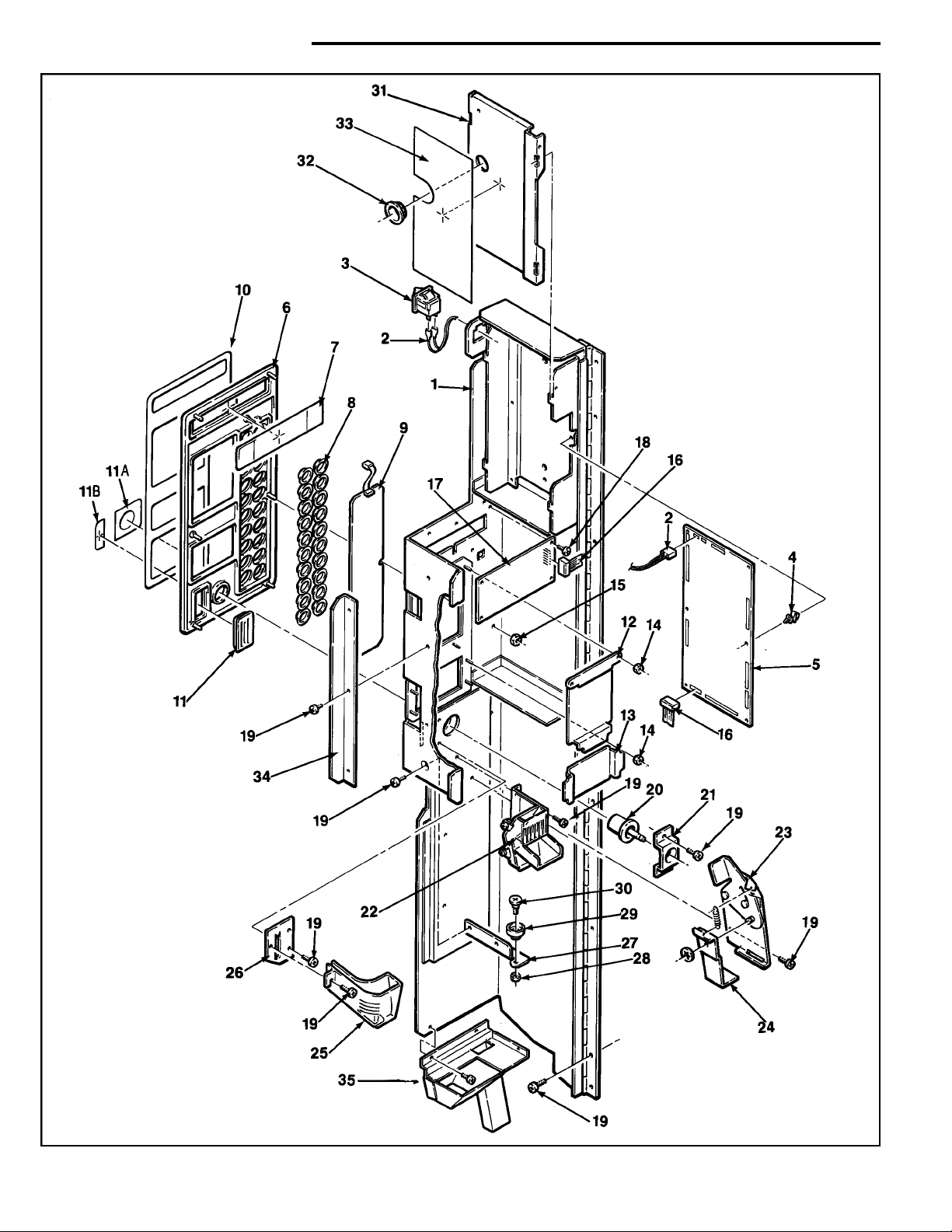
swing out – panel assembly
21
Page 26
swing out – panel assembly
Item
No. Part No. Description
1 660446 Assembly Complete, Swing Out Panel.
600614 Panel Only.
2 680310 Door Operate Switch Harness.
3 380258 Door Operate Switch.
4 420095 P.C. Board Stand Off.
5 360165 Control Board.
380308 Battery (Not Shown)
6 660368 Front Bezel, Assembly Complete. Black.
660368-1 Front Bezel, Assembly Complete. Brown.
660368-2 Front Bezel, Assembly Complete. Gray.
320057-1 Front Bezel Only.
7 440310 Display Lens.
8 440304 Selector Button. Quantity 20.
460415 Decal, Selector Button Background, Black.
460415-1 Decal, Selector Button Background,
Dark Brown.
460415-2 Decal, Selector Button Background,
Medium Gray.
9 660366 Selector Switch & Plate Assembly.
10 460414 Bezel Background. Black.
460414-1 Bezel Background. Multicard.
460414-2 Bezel Background. Dark Brown.
460414-3 Bezel Background.Medium Gray.
11 440309 Coin Entrance.
440309-1 Coin Entrance (Use W/Debitek Only).
11A 460416 Decal, Coin Return Button. Black.
460416-1 Decal, Coin Return.Dark Brown.
460416-2 Decal, Coin Return. Medium Gray.
11B 460417 Decal, Right Side Insert Filler. Black.
460417-1 Decal, Right Side Insert Filler. Dark Brown.
460417-2 Decal, Right Side Insert Filler. Medium Gray.
12 660370 Assembly, Validator Filler.Black.
460424 Validator Decal Only.Black.
660370-1 Assembly, Validator Filler. Dark Brown.
460424-1 Validator Decal Only. Dark Brown.
660370-2 Assembly, Validator Filler.Medium Gray.
460424-2 Validator Decal Only. Medium Gray.
460424-4 Validator Decal. Dark Gray.
460636 Validator Decal French
Item
No. Part No. Description
202708 Adaptor Bracket CBV (Not Shown).
13 660371 Debit Card Filler Assembly. Black.
460425 Debit Card Decal Only. Black.
660371-1 Debit Card Filler Assembly. Dark Brown.
460425-1 Debit Card Decal (Use w/Debitek Only).
460425-2 Debit Card Decal Only. Dark Brown.
660371-2 Debit Card Filler Assembly. Medium Gray.
460425-3 Debit Card Decal Only. Medium Gray.
460637 Debit Card Decal Only French
15 18443 Hex Nut 1/4 Self Threading.
16 680457 Connector Ribbon - Control Board.
17 360166 Display Board W/O Optics.
360166-1 Display Board W/Optics.
460533 Display Board Pad.
18 200-6R6 Screw, Rd. Hd.Type AB #6.
19 276-8R6 Screw, Pan.Had. Phil.Type 23 #8-32 x 3/8.
20 440289 Coin Return Button.Gr ay.
440289-2 Coin Return Button (Use w/Debitek Only).
440289-3 Coin Return Button.Black.
21 201660 Coin Return Support Bracket.
22 660488 Coin Chute Assembly. Plastic.
23 660367 Coin Return, Assembly Complete.
640152 Coin Return Bracket Only.
751-25 Retaining Ring (1/4).
400034 Spring, Indexing Lever.
24 201703 Coin Return Link.
25 440311 Coin Chute.
26 201712 Coin Chute Support Bracket.
27 660445 Panel Latch, Assembly Complete.
202121 Latch, Bracket Only.
28 437-41 Nut 1/4-28 Keps.
29 440362 Shelf Roller.
30 300203 Shelf Roller Screw.
31 660448 Control Board Cover Assembly.
660448-3 Control Board Cover Assembly England
660448-2 Control Board Cover Assembly French
202175 Cover Only.
32 420040-3 Hole Snap Bushing.
33 460514 Instructions, Control Board.
460539 Instructions, Control Board. French.
460657 Instructions, Control Board England
460575 Instructions, Control Board Export
34 202136 Panel Stop. (111,112 Only).
35 750182 Assembly Complete.Coin Chute.
(2 pcs.)
22
Page 27

snack shelf
23
Page 28

snack shelf
Item
No. Part No. Description
1 750121-3 Assembly Complete Snack Shelf w/o Spirals
750162
600240-3 Snack Shelf Only.
2 750159 Kit, Dual Spiral Add-On.
360169 Dual Spiral Motor Only.White.
4 360138 Vend Motor Complete. White.
5 300203 Shelf Roller Screw.
6 440362 Shelf Roller.
7 437-41 Nut, Keps (1/4 x 28).
8 305-8R6 Screw Pan Head. Phillips. Plastite (8-16 x 3/8).
9 440285 Price and Selection Tab Holder.
10 460346 Item Tabs.
11 460347 Price Tabs. Assorted 25¢ - $1.50.
460602 Price Tabs.Assorted $3.10 - $4.05
460529 Price Tabs. French
460540 Price,Tabs. Mexico
460561 Price Tabs. Spanish
460727 Price Tabs. Italian
460644 Price Tabs. English
12 440367 Dual Spiral Pastry Shelf.Front Only.
13 640101 Spacer, Snack Shelf.
202770 Snack Shelf Extra Extension (Not Shown).
14 400169-1
400170-1
400171-1
400179-1 Dual Spiral Only. Left Hand. 9 Space Chrome.
400178-1 Dual Spiral Only. Left Hand. 7 Space Chrome.
15 400168-1
400120-1
400121-1
400166-1
400164-1
16 276-8R6 Screw, Pan Head.Self-Tap.(8-32 x 3/8).
Assembly Complete. Dual Snack Shelf w/o Spirals.
(See Candy Shelf Additional Price
Sheets Next Page)
Dual Spiral Only.Left Hand.10 Space. Chrome.
Dual Spiral Only.Left Hand.12 Space. Chrome.
Dual Spiral Only.Left Hand.15 Space. Chrome.
Dual Spiral Only.Right Hand. 10 Space. Chrome.
Dual Spiral Only. Right Hand.12 Space. Chrome.
Dual Spiral Only. Right Hand.15 Space. Chrome.
Dual Spiral Only.Right Hand. 9 Space.Chrome.
Dual Spiral Only.Right Hand. 7 Space. Chrome.
Item
No. Part No. Description
17 600601 Shelf Plug.Bracket Only.
18 420142-2 Pin Drive.
19 660435-2
680446 Harness, Pastry Shelf Only.
20 440366 Spiral Retainer. Left Hand. Gray.
21 440287 Spiral Retainer. White.
22 201534 Front Support Only.
23 660330-2 Assembly Product Rail. For Use W/Pastry.
660330-4 Product Rail for Use W12 Oz. Cans.
660191-8 Assembly Product Rail for Use With Kit Kat.
440148-1 Plastic Product Rail Only.
600723 Metal Rail R.R.Batter y.
24 200913
25 750083 Kit, Can Dispenser.
26 400127-1 Snack Spiral. 10 Space, Chrome.
400128-1 Snack Spiral. 12 Space, Chrome.
400129-1 Snack Spiral. 15 Space, Chrome.
400136-1 Snack Spiral. 30 Space, Chrome.
400137-1 Snack Spiral. 40 Space, Chrome.
400153-1 Snack Spiral. 7 Space, Chrome.
400162-1 Snack Spiral. 6 Space, Chrome.
400163-1 Snack Spiral. 18 Space, Chrome.
14000002 Snack Spiral. 5 Space, Chrome.
27 440201 Drive Cam.Rear.
28 751-31 Retaining Ring (#31).
29 440200 Drive Cam. Front.
30 300184 Shoulder Bushing.
277-10R8 ScrewType 23 (#10-32 x 1/2).
31 400094 Actuator Wire.
32 305-8R6 Screw Pan Hd.Phillips Plastite (8-16 x 3/8).
33 440196 Price And Selection Trim.
34 440199 Stop Lever.
35 440198 Leg, Top Can Guide & Sign Trim.
36 440197 Top, Can Guide & Sign Trim.
37 600308 Can Dispenser. Trough Only.
38 640109 Cam., Mtg. Bracket & Spring Assembly.
Assembly Complete. Harness and Plug Bracket.
Rear Support Bracket Only.Use W/Pastry Spiral.
24
Page 29

candy shelf
25
Page 30

candy shelf
Item
No. Part No. Description
1 750122-3 Assembly Complete. Candy Shelf w/o Coils.
750122-6 Assembly Complete. Candy Shelf w/o Coils.
9 Selections.
600239-2 Candy Shelf Only.
600662 Candy Shelf Only.9 Selections.
3 360138 Vend Motor Complete. White.
360155
750135 Kit, Half-cycle Add-on.
4 305-8R6 Screw, Pan Hd.Plastite (#8 x 3/8).
5 300203 Screw, Shelf Roller.
6 440362 Shelf Roller.
7 437-41 Nut, Keps (1/4 x 28).
8 440262 Price and Selection Tab Holder. Off-set.
340063 Shelf Front Trim. 9 Selections. (Not Shown)
9 460346 Item Tabs.
10 460347 Price Tabs. Assorted 25¢ - $1.50
460602 Price Tabs.Assorted $3.10 - $4.05
460347-1 Price Tabs. All 30¢ - 35¢
460347-2 Price Tabs.All 40¢ - 45¢
460347-3 Price Tabs. All 50¢ - 55¢
460347-4 Price Tabs. All 60¢ - 65¢
460347-5 Price Tabs.All 70¢ - 75¢
460347-6 Price Tabs. All 80¢ - 85¢
460347-7 Price Tabs. All 90¢ - 95¢
460347-8 Price Tabs.All $1.00 - $1.05.
460347-9 Price Tabs. All $1.10 - $1.15.
460347-10 Price Tabs. All $1.20 - $1.25.
460347-11 Price Tabs. All $1.30 - $1.35.
460347-12 Price Tabs. All $1.40 - $1.45.
460347-13 Price Tabs. All $1.50 - $1.55.
460347-14 Price Tabs. All $1.60 - $1.65.
460347-15 Price Tabs. All $1.70 - $1.75.
460347-16 Price Tabs. All $1.80 - $1.85.
460347-17 Price Tabs. All $1.90 - $1.95.
460347-18 Price Tabs. All $2.00 - $2.05.
460347-19 Price Tabs. All $2.10 - $2.15.
460347-20 Price Tabs. All $2.20 - $2.25.
460347-21 Price Tabs. All $2.30 - $2.35.
460347-22 Price Tabs. All $2.40 - $2.45.
460347-23 Price Tabs. All $2.50 - $2.55.
460347-24 Price Tabs. All $2.60 - $2.65.
460347-25 Price Tabs. All $2.70 - $2.75.
460347-26 Price Tabs. All $2.80 - $2.85.
460347-27 Price Tabs. All $2.90 - $2.95.
460347-28 Price Tabs. All $3.00 - $3.05.
460740 Price Tabs.(75¢ - $1.25)
460529 Price Tabs. French.
460540 Price Tabs. Mexico.
460561 Price Tabs. Spanish.
460644 Price Tabs. English.
460727 Price Tabs. Italian.
Vend Motor Complete.Half-Cycle. Brown & White
Item
No. Part No. Description
11 660178 Assembly, Candy Spacer.
12 276-8R6 Screw Pan Hd.Self Tap (8-32 x 3/8).
13 600601 Shelf Plug, Bracket Only.
14 420142-2 Drive Pin.
15 660435-1 Harness & Bracket Complete.
680445-1 Harness, Candy Shelf Only.
16 440141-1 Candy Product Pusher.
17 660296 Small Product Guide.
660503 Product Guide Assembly For Use w/ Half
Cycle Motor.
18 201258 Front Support Only.
19 660191 Assembly Product Rail.
For Use w/Candy Spiral.
440148-1 Plastic Product Rail Only.
600618 Product Rail For Use W/ 12 Oz.Cans.
660191-8 Product Rail for Kit Kat.
20 200913 Rear Support Bracket Only.
21 400120-1 12 Space Candy Spiral, Chrome.
400121-1 15 Space Candy Spiral, Chrome.
400122-1 18 Space Candy Spiral, Chrome.
400123-1 24 Space Candy Spiral, Chrome.
400135-1 30 Space Candy Spiral, Chrome.
400138-1 40 Space Candy Spiral, Chrome.
400164-1 7 Space Candy Spiral, Chrome.
400166-1 9 Space Candy Spiral, Chrome.
400167-1 6 Space Candy Spiral, Chrome.
400168-1 10 Space Candy Spiral, Chrome.
22 440287 Spiral Lock.
26
Page 31

convertible shelf
27
Page 32

convertable shelf
Item
No. Part No. Description
1 750147-6 Assembly Complete. Convertible Shelf.
(5 Snack Selections).W/o spirals.
750147-7 Assembly Complete. Convertible Shelf.
(4 Snack Selections and 2 Candy).W/o spirals.
750147-8 Assembly Complete. Convertible Shelf.
(3 Snack Selections and 4 Candy).W/o spirals.
750147-9 Assembly Complete. Convertible Shelf.
(2 Snack Selections and 6 Candy).W/o spirals.
750147-10 Assembly Complete. Convertible Shelf.
(1 Snack Selection and 8 Candy).W/o spirals.
750147-11 Assembly Complete. Convertible Shelf.
(10 Candy Selections).
750162 Assembly Complete. Dual Spiral Snack Shelf.
W/o Spirals.
750159 Kit, Dual Spiral Add-On.W/o spirals
(Use per selection).
600240-3 Convertible Snack Shelf Only.
2 300203 Screw, Shelf Roller.
3 440362 Roller, Shelf.
4 437-41 Nut, Keps (1/4 x 28).
5 305-8R6 Screw Pan Hd.Phillips. Plastite (8-16 x 3/8).
6 460346 Item Tabs.
7 460347 Price Tabs.Assorted 25¢ - $1.50.
460602 Price Tabs Assorted $3.10 - $4.05
460347-1 Price Tabs.All 30¢ - 35¢.
460347-2 Price Tabs. All 40¢ - 45¢.
460347-3 Price Tabs. All 50¢ - 55¢.
460347-4 Price Tabs. All 60¢ - 65¢.
460347-5 Price Tabs.All 70¢ - 75¢.
460347-6 Price Tabs.All 80¢ - 85¢.
460347-7 Price Tabs. All 90¢ - 95¢.
460347-8 Price Tabs. All $1.00 - $1.05.
460347-9 Price Tabs.All $1.10 - $1.15.
460347-10 Price Tabs. All $1.20 - $1.25.
460347-11 Price Tabs. All $1.30 - $1.35.
Item
No. Part No. Description
460347-12 Price Tabs. All $1.40 - $1.45.
460347-13 Price Tabs. All $1.50 - $1.55.
460347-14 Price Tabs. All $1.60 - $1.65.
460347-15 Price Tabs. All $1.70 - $1.75.
460347-16 Price Tabs. All $1.80 - $1.85.
460347-17 Price Tabs. All $1.90 - $1.95.
460347-18 Price Tabs. All $2.00 - $2.05.
460347-19 Price Tabs. All $2.10 - $2.15.
460347-20 Price Tabs. All $2.20 - $2.25.
460347-21 Price Tabs. All $2.30 - $2.35.
460347-22 Price Tabs. All $2.40 - $2.45.
460347-23 Price Tabs. All $2.50 - $2.55.
460347-24 Price Tabs. All $2.60 - $2.65.
460347-25 Price Tabs. All $2.70 - $2.75.
460347-26 Price Tabs. All $2.80 - $2.85.
460347-27 Price Tabs. All $2.90 - $2.95.
460347-28 Price Tabs. All $3.00 - $3.05.
460740 Price Tabs.(75¢ - $1.25)
460529 Price Tabs. French.
460540 Price Tabs. Mexico.
460561 Price Tabs. Spanish.
460644 Price Tabs. English.
460727 Price Tabs. Italian.
8 440262 Price and Selection Tab Holder, Offset Candy.
(Please see Page 25, Item #21 for Candy Spirals).
9 440285 Price and Selection Tab Holder, Snack.(Please
see Page 23, Item #26 for Snack Spirals).
10 200753-2 Shelf Divider.Candy.
11 660178 Assembly Candy Spacer.
12 276-8R6 Screw Pan Hd.Self-Tap (8-32 x 3/8).
13 420142-2 Pin, Shelf Plug.
14 660435 Harness, Candy Shelf with Plug Bracket.
600601 Shelf Plug Bracket Only.
15 360138 Vend Motor Complete.White.
750150 Kit, Convertible Shelf. 2 Selection Add-On.
16 440287 Spiral Lock.
28
Page 33

gum & mint shelf
29
Page 34

gum & mint shelf
Item
No. Part No. Description
1 660316 Assembly Complete. Gum & Mint Shelf.
660316-3 Assembly Complete. Gum & Mint Shelf,
Export Only.
600420 Gum and Mint Shelf Only.
600460-1 Gum and Mint Shelf Only. Export.
750165 Kit, Gum and Mint Add-On.
750165-9 Kit, Assembly Complete
Gum and Mint Shelf
Australia.Add-on.
2 420040-9 Snap Bushing and Hole Plug.
3 201412 Thin Mint Adapter (2 per selection).
4 201458 Gum and Mint Rear Pusher Stop.
201458-2 Gum and Mint Rear Pusher Stop,
Export Only.
5 276-8R6 Screw, Pan Hd.Self-Tap Phillips
(8-32 x 318).
6 217-8R22 Screw, Pan Hd.Phillips Type AB (1-3/8).
7 300184 Shoulder Bushing.
277-10R8 Screw Type 23 (#10-32 x 1/2).
8 201454-1 Gum and Mint Shelf Latch. Left Side.
9 360105 Gum and Mint Motor.White
10 420089 Screw,100° Flat Hd. (6-32 x 1/2).
11 600427 Gum and Mint Plug Mounting Bracket.
12 440267 Ejector, Gum and Mint.
13 440266 Gum and Mint Shelf Front Base.
14 305-7R16 Screw, Pan Hd.Plastite (#7 x 1).
15 460352 Decal, Gum and Mint Shelf Latch.
16 440270 Display Stop. Gum and Mint Column Front.
17 440273 Gum and Mint Shelf Front.
Item
No. Part No. Description
18 305-7R22 Screw, Pan Hd.Plastite (#7 x 1-3/8).
19 680305 Harness, Gum and Mint Shelf.
660340 Harness, Gum and Mint Shelf.W/BRKT
380229 Gum and Mint Shelf Plug Only.
660340-1 Harness G & M Shelf & Bracket,
Export Only.
680322 Harness Only. Export.
20 201414 Strap, Gum and Mint Pusher Stop.
201527 G & M Pusher Stop Strap, Export Only.
21 262-6R5 Screw, Flat Hd. Phil. Type 23 (6-32 x 5/16).
22 400106 Spring, Gum and Mint Pusher Return.
23 660314 Assembly, Complete Gum and Mint
Display. Hinge.
660314-1 Assembly, Complete Gum and Mint
Display Hinge, Export Only.
24 201454 Gum and Mint Shelf Latch. Right Side.
25 420023 Wing Nut (8-32).
26 201411-1 Column Spacer, Left.
27 201411 Column Spacer, Right.
28 420296 Shelf Grommet. (NGS #1 22).
29 460351 Decal, Caution. Gum and Mint Shelf.
30 201409 Cover,Gum and Mint Shelf.
201530 Cover Gum and Mint Shelf, Export Only.
31 660313 Assembly, Complete. Gum and Mint
Pusher and Spring.
32
801G125-12
33 440265 Pusher Only.
34 440274 Roller, Gum and Mint Pusher.
35 201691 Shelf Closer.
Roll Pin (1/8 x 3/4).
30
Page 35

delivery bin
31
Page 36
swing out – panel assembly
delivery bin
Item
No. Part No. Description
1 660558 Delivery Bin Assembly. Complete. Black.
660558-2 Delivery Bin Assembly. Complete. Gray.
600704 Delivery Bin.
2 640187-1 Arm Mounting Bracket.
3 438-8 Nut, Keps. No. 8-32.
4 640098 Inner Door Bin Arm.
5 640100-1 Bin Door Drive Assembly.
6 751-37 Retaining Ring No.37.
7 750183 Kit, Lower Bracket Repair.
8 640097 Door Drive Arm.
Item
No. Part No. Description
9 440129 Door Bearing.
420282 Bin Door Washer (Not Shown).
10 200763 Inner Door.
200763-5 Inner Door Steel
11 276-846 Screw, Pan Hd., Self Tap. (8-32 x 3/8)
12 440373 Door, Delivery Bin.Black.
440373-2 Door, Delivery Bin.Gr ay.
15 202285 Arm Mounting Bracket (Lock Side).
16 200902 Baffle, Rear Delivery Bin.
17 200906 Delivery Bin Anchor Strap.
18 420315 Delivery Bin Pad Assembly for Can
Dispenser.
32
Page 37

main junction box
33
Page 38
main junction box
Item
No. Part No. Description
1 660489 Assembly Complete, Junction Box.
110 Volts.
660489-2 Assembly Complete, Junction Box.
220 Volts. Export Only.
660489-1 Assembly Complete, Junction Box.
240 Volts. Export Only.
660489-3 Assembly Complete. Junction Box.
115 Volt. Export. Mexico.
202249 Junction Panel Only.
2 680511 Junction Box Harness, Domestic.
680510 Junction Box Harness. Export Only.
3 202087 Cover, Junction Panel.
4 276-8R6 Screw, Pan Hd.Phil. Type 23 (8-32 x 3/8).
7 380291 Push Mount Cable Tie.
8 437-10 Nut, Keps,10-32.
Item
No. Part No. Description
9 680452 Changer Harness. U.S.
680516 Changer Harness (L+).
10 276-6R6 Screw Pan Hd.Phil. Type 23 (6-32 x 3/8).
11 360164 Transformer, Domestic.
360167 Transformer, Export.
12 380241 Circuit Breaker.
13 380243 Switch, On/Off.
14 360109 Control Power Board. U.S. Only.
15 420095 PC Board Stand-Offs. U.S.Only.
16 460506 Decal, Breaker Identification. Domestic.
460578 Decal, Breaker Identification. Export.
460458-2 Not Shown. Voltage Decal 240 Volt.
460458-1 Not Shown. Voltage Decal 220 Volt
460535 Decal, Breaker Identification. French.
Part No. Description
360163 Line Cord Set. U.S.
680305 Harness, Gum and Mint Shelf.
680445-1 Harness, Candy Shelf.
680446 Harness, Pastry Shelf.
660442 Cabinet Back Harness 5 Shelves.
660442-1 Cabinet Back Harness 6 Shelves.
660442-2 Cabinet Back Harness 7 Shelf.
680452 Harness, Mars Changer Hook-Up.
680542 Harness Interconnect 115.
680544 Line Cord Israel Only.
680456 Harness, Fan or Light.
680464 Assembly Lamp Harness.
680310 Harness, Operate Switch.
electrical harnesses
Part No. Description
680355 Harness, Mars/Coinco Bill Validator.
Hook-Up. 24 Volt.
680457 Connector Ribbon.
680475 Harness, Mars/Coinco Bill Validator.
Hook-Up. 115 Volt.
680319 Harness, Mars Changer Hook up. Export Exec.
660505-2 Assy. Line Cord Australia.
660483 Assy. Complete Line Cord. Export.
660505-3 Assy. Complete. Line Cord. Israel.
680475-1
680577 Harness Printer.
680509 Harness, Board to Printer.
660505-5 Assy Complete Line Cord Multisnack
Harness, Mars Validator w/Card Reader w/ 2 pin molex
34
Page 39

chill machine supplement
35
Page 40

chill machine supplement
Item
No. Part No. Description
660451 Assembly Complete. Cabinet & Insulation Only.
Model 113. Specify Color.
2 276-8R6 Screw, Pan Hd.Phillips (8-32 x 3/8).
3 202404 Air Duct Top Support -113.
4 660455 Assembly, Air Duct.
5 460468 Door Gasket.Order by Inches (Qty. 80).
6 680458-1 Harness, Power Inlet Box.
680503 Harness, Power Interlock Box.Export.
7 660447-1 Assembly Complete. Power Interconnect Box.
660486 Assembly, Power Interconnect Box.Export.
Item
No. Part No. Description
8 460468 Gasket. Order by Inches.
9 202145 Right Retainer.
10 202144 Left Retainer.
11 660514 Assembly Complete. Cooling Unit.115 Volt.
R134A.
660513 Assembly Complete. Cooling Unit.
220/240 Volt, Export. R134A.
12 660504 Assembly.Vent Screen.
13 660505 Assembly. Line Cord. Cooled.
14 276-8R8 Screw Pan HD Phillips (8.32X1/2)
15 202471 Deflector
36
Page 41
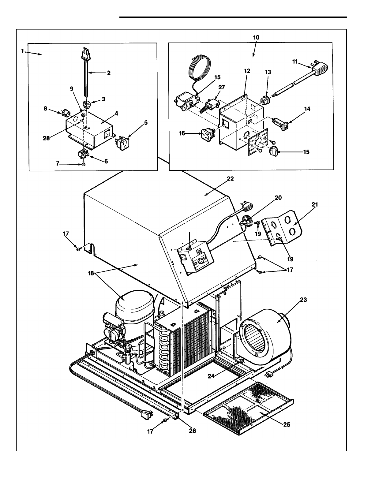
chill machine supplement
37
Page 42

chill machine supplement
Item
No. Part No. Description
1 660447-1 Assembly Complete. Power Interconnect Box.
660486 Assembly Complete. Power Interconnect Box.
Export.
2 680458-1 Harness, Power Interlock Box.
680503 Harness, Power Interlock Box. Export.
3 380052-5 Strain Relief Bushing.
4 202122 Power Interconnect Box Only.
202243 Power Interconnect Box. Export.
5 380252 Receptacle W/Ground. Snap in.
6 380285 Terminal Block.
7 210-8R6 Screw Rd.Hd.Phillips (#8 x 3/8).
8 420040-2 Snap Bushing (1/2).
380078 Cable Tie (Not Shown).
9 404-6 Hex Nut (6-32)
10 660497 Assembly Complete. Cold Control Housing.
660484 Assembly Complete.Cold Control. Export.
460603 Decal “Press to Reset” (Not Shown)
11 680468 Cold Control Cord.
680504 Cold Control Cord.Export.
12 202164 Cold Control Housing Only.
202246 Cold Control Housing.Export.
13 380052-1 Strain Relief Bushing (14/3).
14 380241-1 Circuit Breaker 15 amp.
Item
No. Part No. Description
15 360182 Cold Control Switch. Export & U.S.
16 380252 Receptacle W/Ground. Snap In.
17 276-8R6 Screw, Pan Hd., Type A, Phillips (8-32 x 3/8).
18 660514 Assembly Complete. Cooling Unit 115 Volt.
660513 Assembly Complete. Cooling Unit 220/240
Volt.Export. Cooling units use 11 oz. of
134A Refrigerant
(PARTS #19-21 NOT INCLUDED)
19 210-8R6 Screw Pan Hd., Type A, Phillips (#8 x 3/8).
20 420035-1 Cable Clamp (3/8).
21 202173 Guard. Cold Control.
22 660470 Assem. Comp., Condensing Cover & Insul.
23 660466-1 Assembly Complete. Blower,115 Volt.
660466 Assembly Complete. Blower 220/240 Volt.
Export.
24 438-41 Keps Nut (1/4-20).
25 600626 Assembly, Vent Screen.
26 202142 Guide Angle. Left.
202143 Guide Angle. Right (Not Shown).
27 680505 Harness, Cold Control. Export.
28 440065 Insulation Mylar. (Not Shown).
38
Page 43

AP II style
Item
No. Part No. Description
1 340044-5 Trim, Top, For use wNinyl Insert.
2 440258-2 Insert Top Trim “Snacks”.
440285-3 InsertTop Trim “Cigarettes”.
3 340057 Trim, Outside Vertical (Right or Left).
4 340058-2 Trim, Inside Vertical.(Right or Left).
5 PANEL, LEFT SIDE VERTICAL.
202059 Presidential Walnut, Vinyl.
202059-1 Honeytone Teak, Vinyl.
202059-2 Painted, Specify Color.
6 PANEL RIGHT SIDE VERTICAL-LOWER.
202061 Presidential Walnut.
202061-1 Honeytone Teak.
202061-2 Painted. Specify Color.
7 340058 Trim, Inside Horizontal.
8 PANEL DELIVERY TRAY.
201356 Presidential Walnut, Vinyl.
201356-31 Regency Walnut, Vinyl.
201356-3 Honeytone Teak, Vinyl.
201356-6 Painted, Specify Color.
9 340055-3 Trim, Inside Horizontal.
10 PANEL, LOWER HORIZONTAL.
200296-36 Presidential Walnut, Vinyl.
200296-39 Honeytone Teak Vinyl.
200296-42 Painted, Specify Color.
11 600600 Door Only, Specify Color.
12 PANEL RIGHT SIDE VERTICAL-UPPER.
202060 Presidential Walnut, Vinyl.
202060-1 Honeytone Teak.Vinyl.
202060-2 Painted. Specify Color.
39
Page 44

Cover-up plate 3
Item
No. Part No. Description
1 660231-3 Trim, Horizontal w/Black Stripe.
2 PANEL, COVERPLATE 3".
201417 Presidential Walnut, Vinyl.
201417-4 Regency Walnut, vinyl.
201417-5 Honeytone Teak, Vinyl.
201417-6 Painted, Specify color.
201417-21 Dove Gray.
3 340057 Trim, Outside Vertical (Right or Left).
4 340058-4 Trim, Inside Vertical (Right or Left).
5 PANEL, LEFT SIDE VERTICAL.
202059-4 Presidential Walnut, Vinyl.
202059-12 Regency Walnut, Vinyl.
202059-17 Honeytone Teak, Vinyl.
202059-6 Painted, Specify Color.
202059-5 Port Au Prince, Vinyl.
202059-54 Sterling Royce.
202059-16 Dove Gray.
6 PANEL, RIGHT SIDE VERTICAL-LOWER.
202061 Presidential Walnut, Vinyl
202061-10 Regency Walnut, Vinyl.
202061-1 Honeytone Teak, Vinyl.
202061-2 Painted, Specify Color.
202061-5 Port Au Prince, Vinyl.
202061-44 Sterling Royce.
202061-14 Dove Gray.
7 340058 Trim, Inside Horizontal.
8 PANEL, DELIVERYTRAY.
201356 Presidential Walnut, Vinyl.
201356-31 Regency Walnut, Vinyl.
201356-3 Honeytone Teak, Vinyl.
201356-6 Painted, Specify Color.
201356-36 Dove Gray.
9 PANEL, LOWER HORIZONTAL.
200296-36 Presidential Walnut, Vinyl.
200296-37 Regency Walnut, Vinyl.
200296-39 Honeytone Teak, Vinyl.
200296-42 Painted, Specify Color.
200296-9 Dove Gray.
10 600600 Door Only, Specify Color.
11 PANEL, RIGHT SIDE VERTICAL-UPPER.
202060-4 Presidential Walnut, Vinyl
202060-12 Regency Walnut, Vinyl.
202060-17 Honeytone Teak, Vinyl.
202060-5 Port Au Prince, Vinyl.
202060-6 Painted, Specify Color.
202060-56 Sterling Royce.
202060-16 Dove Gray.
Item
No. Part No. Description
40
Page 45

high techstyle
Item
No. Part No. Description
1 340042-3 Trim, Top Only. Use only Vinyl Insert.
2 201260 Vinyl Insert, Top Trim, Sterling Royce Vinyl.
3 340057-2 Trim, Outside Vertical (Right or Left).
4 340058-7 Trim, Inside Vertical (Right or Left).
5 PANEL, LEFT SIDE VERTICAL.
202059-9 Sterling Royce Vinyl.
6 PANEL, RIGHT SIDE VERTICAL- LOWER.
202061-4 1 Sterling Royce Vinyl.
7 340058 Trim, Inside Horizontal.
8 PANEL, DELIVERY TRAY.
201356-3 1 Sterling Royce Vinyl.
9 340055-3 Trim, Inside Horizontal.
10 PANEL, LOWER HORIZONTAL.
200296-54 Sterling Royce Vinyl.
11 600600 Door Only. Specify Color.
12 PANEL, RIGHT SIDE VERTICAL-UPPER.
202060-9 Sterling Royce Vinyl.
41
Page 46

tron II style 113
Item
No. Part No. Description
1 340055-9 Trim Horizontal, Top & Bottom, Black.
2 201417-2 Cover Up Plate, Galvanized.
440312-1 Top Insert, Black.
3 660231-3 Trim, Horizontal w/Black Stripe.
4 340057-2 Trim, Outside Vertical, Left or Right, Black.
5 340058-8 Trim, Inside Vertical, Left or Right, Black.
6 202059-16 L S V P Dove GrayTron.
7 340058 Trim, Horizontal, Window.
8 201356-34 Delivery Tray Panel, Sterling Royce.
9 200296-9 Panel Lower Horizontal, Dove Gray, Tron.
10 202061-14 R S V P Dove Gray, Tron, Lower.
11 202060-16 Panel, Right Side Vertical - Upper. Dove Gray.
12 600600 Door Only.Specify Color.
Item
No. Part No. Description
42
Page 47

genesis styling 113
Item
No. Part No. Description
1 340042-8 Top Trim Only.
2 200526-1 Panel, Top Trim. Black Hyde.
3 340057 Trim, Outside Vertical.Silver.
4 202059-42 Panel, Left Side Vertical.Black Hyde.
5 340058-6 Trim, Inside Vertical. Black.
6 340058-5 Trim, Horizontal Window. Black.
7 201356-3 Panel, Delivery Tray. Sterling Gray.
8 340055-9 Trim, Horizontal.Black.
9 201692-4 Panel, Lower Horizontal.Black Hyde.
201678 Bottom Vinyl Door Edging (Not Shown).
420186 Screw, HWH Drill Pt.Black. (6-201/2) Qty. 5.
10 202061-3 Panel, Right Side Vertical. Lower.Blk. Hyde.
11 202060-42 Panel, Right Side Vertical. Upper. Blk. Hyde.
Item
No. Part No. Description
43
Page 48

Connectors
4 PIN INTERNATIONAL MOLEX PLUG
3 8 0 2 9 6
3 PIN INTERNATIONAL MOLEX PLUG
FREE HANGING - 380286
PANEL MOUNT - 380286-1
4 PIN INTERNATIONAL MOLEX
R E C E P TAC L E
3 8 0 2 9 3
3 PIN INTERNATIONAL MOLEX
R E C E P TAC L E
3 8 0 2 8 8
44
Page 49
mis printout for 110 series snack
REPORT DATE 09/23/94
REPORT TIME 09:05
ID101 12345678
EA301 6
EA203 0
VA101 20.45
VA102 38
VA202 19
VA301 3.25
VA302 6
VA702 0.00
CA306 12.45
CA308 8.00
DA201 0.00
COMMENTS
Special notes or Service Mode For Access in BOLD
Eight digit machine ID number - Mode Service 0300
Number of electronic audits
Number of Audit Resets
Cash Meter, all vends - Mode Service 8
Vend Counter all vends - Mode Service 8
Counter,Test Vends - Mode Service 9
Cash Meter, Winner Vends - Mode Service 0100
Vend Counter, Winner Vends - Mode Service 0100C
Cash Meter Discount Vends - Mode Service 0800 & 0110
Cash to Coin Box
Value of Bills Accepted
Cash Meter, Debit Card Sales
DA202 00
CA602 40
EA1 *1*23*09:00*01
EA1 *2*23*08:00*21
EA1 *3*22*09:00*11
EA1 *4*21*09:00*15
PA 1 *11**A1,A3,A5,A7
PA202 10
PA202 5.00
EA1 *11*23*08:00
PA1 *21**B1,B3,B5,B7
PA202 6
Vend Counter, Debit Card Sales
Number of Door Openings
Time of most recent door open (hour)
*Number*Day of month*hour:OO*Duration of opening
Time of second most recent door open
Time of third most recent door open
Time of fourth most recent door open
Product Code (* 11) and Selections assigned to that code
Vend Counter, Product Code (*11) - Mode Service 0500
Cash Meter, Product Code (* 111
Most Recent Product Code Vend (hour)
*Product Code*Day of month*hour:OO**
Product Code (*21) and Selections assigned to that code
Vend Counter, Product Code {*21) - Mode Service 0600
PA202 3.00
EA1 *21*23*08:00
END OF PRINTOUT`
Note: Dotted lines added to printer tape for clarity.
All clock dependent functions require that time & date are correctly set in Service Mode 0200.
Revision M or higher software required. Mode Service 0501
45
Cash Meter, Product Code (*21)
Most Recent Product Code Vend ((hour)
Page 50

trouble shooting chart
Problem Cause Remedy
No power No lights Check wall outlet for correct
wiring, and line cord.
See page 3.
Lights work - no power Check transformer outputs
to board & circuit breakers
No power to the board Check wiring connections
Defective power board Replace power board
Display blank Check for voltage at P1-110
Machine-4.7 volts between
yellow wires
LCM machines-24VAC at
white wires at P1
Won't take coins No power to machine Check wall outlet, line cord
& voltage
Defective changer Replace changer
Machine only accepts one coin Machine lost its vend prices -
reprice and test
Defective circuit breaker Replace circuit breaker
No power to coin payouts Replace power board or logic
board on LCM machines
Won't payout coins/incorrect No voltage Check voltages
change returned
Won't take bills No coins in coin tubes Fill coin tubes
Defective power board Replace power board
Defective coin mechanism. Replace coin mechanism.
Jammed coins in tube Remove coins
Belts or stacker doesn't run Check for 110 VDC on power
on power-up board
Belts run-bill goes half way Replace validator
but won't accept
Incorrect inventory Check inventory of coin
mechanism by entering service
mode 10-125
46
Page 51

trouble shooting chart
Problem Cause Remedy
Says make another selection Motor 1⁄2 cycled Home motor and retry /LCM do
mode 5 test vend
Selection lost its price Reset prices
Motor won't turn Swap shelves with another shelf
and retry
Check shelf harness connection
to board
Check 24VAC to logic board
(blue wires 110) /white wires
LCM
Display messages "Machine use not allowed" Machine set in shutdown mode
see mode 800 in manual
"Buy now & save X%" Machine set in discount mode
see mode 900 in manual
"Free" Winner vend set to 01
Discount set on
Selection priced at 00.00
Free vend on
Use correct change Coin tubes empty Re-fill coin tubes
Says use correct change Replace coin mechanism
with coin tubes full
Spirals turn more than one turn Capacitor discharging current Re-solder capacitor or replace
motor
Loose wire on motor Repair wire
Defective motor switch Replace switch
Defective control board Replace control board
More than one motor turns One of the motor wires is Check each individual motor
together shorting out for loose or pinched wire
Defective control board Replace control board
47
Incorrect vend motors Black bodied motors for LCM
installed
Ivory bodied motors for 110
series
Page 52

trouble shooting chart
Problem Cause Remedy
Unable to enter service mode Check plugs on control board Power down and remove and
install connectors
Defective changer Replace changer
Defective main board Replace board
Coin mechanism jackpots Incorrect voltage Check voltages± 10%
Defective coin mechanism Replace coin mechanism
Defective board Replace control board
Motor doesn't home on door No voltage Check for correct voltages
close
Defective door switch Replace door switch
Defective board Replace board
48
Page 53

connector pinouts
P1 POWER IN
1 24 VAC HOT
2 KEY
3 24 VAC NEUTRAL
4 7.0 VAC HOT
5 7.0 VAC NEUTRAL
6 4.7 VAC HOT
7 4.7 VAC NEUTRAL
8 4.7 VAC CENTER TAP
9 24 VAC 50 Ma
10 24 VAC 50 Ma
P2 MOTOR DRIVE
1 ROW A
2 ROW B
3 ROW C
4 ROW D
5 ROW E
6 ROW F
7 ROW G
8 ROW H
9 COL 1
10 COL 2
11 COL 3
12 KEY
13 COL 4
14 COL 5
15 COL 6
18 COL 7
17 COL 8
18 COL 9
19 COL 10
P3 DISPLAY
1 FIL
2 FIL
3 5VDC
4 DOR
5 CT
6 -27VDC
7 DATA
8 CLOCK
9 DOR
10 SERIAL RES.5VDC
11 SERIAL RES. SIGNAL
12 OPTICS GND
13 OPTICS RECEIVE
14 OPTICS TRANSMIT
15 OPTICS 5 VOLTS
P4 MODE KEY SWITCH
1 KEY SWITCH CONTROL
2 KEY SWITCH M/O
P6 - BILL VALIDATOR
1 ESCRCW HIGH
2 $1 HIGH
3 $2 HIGH
4 $5 HIGH
5 ESCROW ENABLE (LOW)
6 $ ENABLE
7 $ ENABLE
8 $ ENABLE
9 CREDIT
10 (KEY)
11 GND
12 24VAC HOT
13 24VAC NEUTRAL
14 +15 VDC
15 +9.75 VDC
P7 TRC-6000/6010 Series Mech
1 24 VDC RET NF
2 KEY
3 24 VDC HOT NF
4 KEY
5 DATA
6 INT
7 AE
8 MECH RESET
9 SEND
10 +5VDC
11 GND
12 .05¢ DISPENSE
13 .10¢ DISPENSE
14 .25¢ DISPENSE
15 $1.00 DISPENSE
P9 - MS 1600/EUROPEAN CARD READER
1 REC +
2 REC
3 XMIT
4 GND
5 XMIT +
6 24VAC HOT
7 KEY
8 24 VAC NEUTRAL
9 EXACT CHANGE
P10 - RS232 SERIAL INTERFACE
1 RECEIVE DATA
2 GND
3 TRANSMIT DATA
4 KEY
5 GND
P5 - DOOR SWITCH
1 SIGNAL
2 GND
49
Page 54
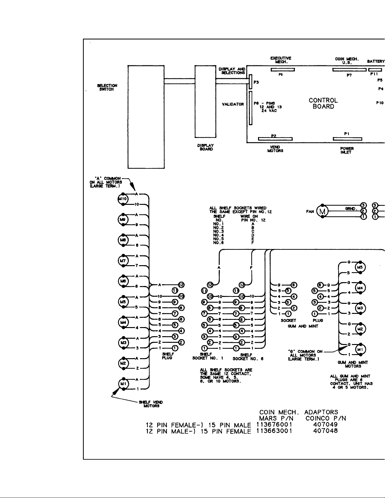
Page 55

Page 56

Page 57

 Loading...