

Automatic Heating Modulex EXT 440, Modulex EXT 550, Modulex EXT 660, Modulex EXT 770, Modulex EXT 900 Installation And Servicing Instructions

Modulex EXT
440 - 550 - 660 - 770 - 900
Modular Condensing Boiler
Installation and Servicing Instructions

Warning: this manual contains instructions to be used exclusively by the
installer and/or a competent person in accordance with the current laws in
force.
The end user MUST not make any alterations to the boiler.
Failure to follow the instructions indicated in this manual, which is supplied
with the boiler, could cause injury to persons, animals or damage to property.
UNICAL shall not be held liable for any injury and/or damage.
CONTENTS
1 GENERAL INFORMATION ................................................................................................................................................................................... 4
1.1 Symbols used in this guide .......................................................................................................................................................................... 4
1.2 Correct use of the appliance ....................................................................................................................................................................... 4
1.3 IInformation to be passed over to the person in charge of the appliance ................................................................................................ 4
1.4 Safety warnings ............................................................................................................................................................................................ 5
1.5 Data badge .................................................................................................................................................................................................... 6
1.6 General warnings ......................................................................................................................................................................................... 7
2 TECHNICAL FEATURES AND DIMENSIONS ..................................................................................................................................................... 8
2.1 Technical features ........................................................................................................................................................................................ 8
2.2 Dimensions ................................................................................................................................................................................................... 9
2.3 Performance data ....................................................................................................................................................................................... 10
2.4 RHS view showing main components ....................................................................................................................................................... 11
3 INSTRUCTIONS FOR THE INSTALLER ............................................................................................................................................................ 12
3.1 General warnings ...................................................................................................................................................................................... 12
3.2 Installation standards ................................................................................................................................................................................ 13
3.3 Packaging .................................................................................................................................................................................................. 14
3.4 Installation .................................................................................................................................................................................................. 16
3.5 Boiler location in a boiler room .................................................................................................................................................................. 17
3.6 Boiler connection ....................................................................................................................................................................................... 17
3.7 Gas connection ......................................................................................................................................................................................... 18
3.8 Connection return and flow system pipes ............................................................................................................................................... 19
3.9 Primary circuit pump or boiler pump ........................................................................................................................................................ 20
3.10 Additional safety and control devices, according to the Italian Law + primary circuit kit ..................................................................... 21
3.11 Wiring diagram for additional safety devices ........................................................................................................................................... 22
3.12 Safety pressure relief valve ..................................................................................................................................................................... 23
3.13 Mixing header filter .................................................................................................................................................................................... 23
3.14 Ballstop valves .......................................................................................................................................................................................... 23
3.15 Boiler freeze protection ............................................................................................................................................................................. 24
3.16 Mixing header and plate heat exchanger ................................................................................................................................................ 24
3.17 Condensing drain ...................................................................................................................................................................................... 25
3.18 Water treatment ......................................................................................................................................................................................... 26
3.19 Flue chimney connection .......................................................................................................................................................................... 27
3.20 Flue manifold connection .......................................................................................................................................................................... 27
3.21 Operation ................................................................................................................................................................................................... 29
3.22 Electrical connections ............................................................................................................................................................................... 31
3.23 Functional wiring diagram......................................................................................................................................................................... 32
3.24 Wiring diagram for connection and managing......................................................................................................................................... 34
3.25 Installation examples (functional wiring and connections description) .................................................................................................. 36
3.26 Cascade manager BCM ........................................................................................................................................................................... 40
Connections for boilers in cascade, controlled by outer compensators ............................................................................................... 43
3.27 Configuration with a modulating pump ..................................................................................................................................................... 44
3.28 Filling the system ...................................................................................................................................................................................... 45
3.29 Burner Adjustment .................................................................................................................................................................................... 46
3.30 Emergency functions ............................................................................................................................................................................... 49
3.31 Initial Lightning ........................................................................................................................................................................................... 50
4 SERVICING SCHEDULE .................................................................................................................................................................................... 51
5 CE CERTIFICATE ............................................................................................................................................................................................... 56
3

General information
1
GENERAL INFORMATION
1.1 -SYMBOLS USED IN THIS GUIDE
When reading this guide particular care has to be given to the parts marked with the followings symbols:
DANGER!
Indicates serious danger
for your personal safety
and for your life
WARNING!
Indicates a potentially dangerous
situation for the product and the
environment
NOTE!
Suggestions for the
user
1.2 - CORRECT USE OF THE APPLIANCE
The MODULEX appliance has been designed utilizing today’s heating technology and in compliance with the
current safety regulations.However, following an improper use, dangers could arise for the safety and life
of the user or of other people, or damage could be caused to the appliance or other objects.The appliance
is designed to be used in pumped hot water central heating systems. Any other use of this appliance will be
considered improper. UNICAL declines any responsibility for any damages or injuries caused by an improper
use; in this case the risk is completely at the user’s responsibility.In order to use the appliance according
to the scopes it was designed for it is essential to carefully follow the instructions indicated in this guide.
1.3 - INFORMATION TO BE HANDED OVER TO THE USER
The user has to be instructed on the use and operation of his heating system, in particular:
• Hand over these instructions to the end user, together with any other literature regarding this appliance,
placed inside the envelope contained in the packaging. The user has to keep these documents in a safe
place in order to always have them at hand for future reference.
• Inform the user on the importance of air vents and of the flue outlet system, stressing the fact that is absolutely
forbidden to make any alterations to the boiler.
• Inform the user how to check the system’s water pressure as well as informing him how to restore the correct
pressure.
• Explain the function of time and temperature controls, thermostats, heating controls and radiators, to ensure
the greatest possible fuel economy.
• Remind the user that it is obligatory to carry out a comprehensive service annually and a combustion analysis
every two years (in compliance with the national law).
• If the appliance is sold or transferred to another owner or if the present user moves home and leaves the
appliance installed, ensure yourself that the manual always follows the appliance so that it can be consulted
by the new owner and/or installer.
Failure to follow the instructions indicated in this guide, which is supplied with the boiler, could cause injury
to persons, animals or damage to property . The manufacturer shall not be held liable for any such injury and/
or damage.
4

1.4 -SAFETY W ARNINGS
WARNING!
The device should not be used by people with reduced physical, mental and sensory , experience and
knowledge. These people must be well-informed and supervised during the work. Children must be
supervised so they do not play with the appliance.
WARNING!
The installation, adjustment, and servicing of this appliance must be carried out by a competent person and
installed in accordance with the current standards and regulations. Failure to correctly install this appliance
could cause injury to persons, animals or damage to property. The manufacturer shall not be held liable for
any injury and/or damage.
DANGER!
Servicing or repairs of the appliance must be carried out by UNICAL authorised service technicians; UNICAL
recommends drawing up a service contract. Bad or irregular servicing could compromise the safe operation
of the appliance, and could cause injury to persons, animals or damage to property for which UNICAL shall not
be held liable.
Modifications to parts connected to the appliance
Do not carry out any modifications to the following parts:
- the boiler
- to the gas, air, water supply pipes and electrical current
- to the flue pipe, safety relief valve and its drainage pipe
- to the constructive components which influence the appliance’s safe operation
WARNING!
When tightening or loosening the screw pipe connections, use only adequate fork spanners.
The improper use and/or the use of inadequate equipment can cause damages (for example water or gas
leakages).
General information
WARNING!
Indications for appliances operating with propane gas
Ensure yourself that before installing the appliance the gas tank has been purged.
For a correct purging of the tank contact the liquid gas supplier or a competent person who has been legally
authorized.
If the tank has not been correctly purged problems could occur during ignition.
If this occurs contact the liquid gas tank’s supplier.
Smell of gas
If you smell gas follow these safety indications:
- Do not turn on or off electrical switches
- Do no smoke
- Do not use the telephone
- Close the main gas tap
- Open all windows and doors where the gas leakage has occurred
- Inform the gas society or a company specialized in installing and servicing heating systems
Explosive and easily inflammable substances
Do not use or leave explosive or easily inflammable material (as for example: petrol, paint, paper) in the room
where the appliance has been installed.
WARNINGS
The boiler has to be installed in such way to avoid,
under the foreseen operation conditions, the congelation of the water and
to prevent that the control devices are exposed to a temperature
lower than -15°C and higher than 40°C.
The boiler has to be protected against environmental variations with:
- The insulation of the hydraulic pipelines and the condensate evacuation
- The adoption of specific antifreeze products in the C.H. installation.
5

General information
1.5 - DATA PLATE
CE Marking
The CE marking documents that the boilers satisfy:
- The essential requirements of the Directive regarding gas
appliances (Directive 2009-142 EC)
- The essential requirements of the Directive regarding
electromagnetic compatibility (Directive 2004/108 EC)
- The essential requirements of the Efficiency Directive
(Directive 92/42/EEC)
- The essential requirements of the low voltage Directive
(Directive
2006/95EC).
®
3
5
7 8
A
B
C D
21 22
E
27
9
11
13
15
17
19
23
1
2
4
6
10
12
14
16
18
20
24
25
26
LEGEND:
1 = Y ear of CE certification issue
Boiler type
2=
3=Boiler model
4=Number of stars (Directive 92/42/CEE)
5=(S.N°) Serial number
6=P.I.N. code
7=Approved fluing configurations
8=(N0x) N0x class
A = Central Heating circuit features
(Pn) Nominal output
9=
10 = (Pcond) Condensing nominal output
11 = (Qmax) Nominal heat input
12 = (Adjusted Qn) Adjusted for nominal Heat input
(PMS) Max. pressure C.H. system
13 =
14 = (T max) Max. C.H. temperature
B = Domestic Hot Water circuit features
15 = (Qnw) Nominal heat input in D.H.W. mode (if different from Qn)
16 = (D) Specific D.H.W. flow rate according to EN 625 - EN 13203-1
6
28
17 = (R factor) N° taps based on the quantity of water declared EN
13203-1
18 = (F factor) N°stars based on the quality of water declared
EN 13203-1
19 = (PMW) Max. pressure D.H.W. system
20 = (T max) Max. temperature D.H.W system
C = Electrical features
21 = Electrical power supply
22 = Consumption
23 = Protection grade
D = Countries of destination
24 = Direct and indirect country of destination
25 = Gas family
26 = Supply pressure
E = Factory setting
27 = Adjusted for gas type X
28 = Space for national brands

1.6 - GENERAL WARNINGS
General information
This instruction manual is an integral and indispensable part
of the product and must be retained by the person in charge
of the appliance.
Please read carefully the instructions contained in this manual
as they provide important indications regarding the safe
installation, use and servicing of this appliance.
Keep this manual in a safe place for future reference.
The installation and servicing must be carried out in
accordance with the regulations in force according to the
manufacturer’s instructions and by legally competent
authorized persons.
By a competent person, we imply a person who has a
specific technical qualification in the field of components
for central heating systems for domestic use, domestic
hot water production and servicing. The person must have
the qualifications foreseen by the current laws in force.
Bad or irregular servicing could compromise the safe
operation of the appliance, and could cause injury to persons,
animals or damage to property. The manufacturer shall not
be held liable for any such injury and/or damage.
Before carrying out any cleaning or servicing turn off the
electrical supply to the boiler by means of the ON/OFF switch
and/or by means of the appropriate shutdown devices.
In the event of failure and/or faulty functioning of the appliance,
switch off the boiler. Do not attempt to make any repairs:
contact qualified technicians.
Any repairs must be carried out by Unical authorized
technicians and using only original spare parts. Nonobservance of the above requirement may jeopardize the
safety of the appliance.
To guarantee the efficiency and correct functioning of the
appliance it is indispensable to have the boiler serviced
annually by a qualified person.
If the boiler remains unused for long periods, ensure that any
dangerous parts are rendered innocuous.
If the appliance is sold or transferred to another owner or if
the present user moves home and leaves the appliance
installed, ensure yourself that the manual always follows the
appliance so that it can be consulted by the new owner and/
or installer.
Only original accessories must be used for all appliances
supplied with optionals or kits (including electrical ones).
This appliance must be used only for the purposes for which
it has been expressively designed. Any other use shall be
considered incorrect and therefore dangerous
(*).
Do not obstruct the intake/outlet terminal ducts.
7
Technical features and dimensions
TECHNICAL FEATURES
2
AND DIMENSIONS
2.1 - TECHNICAL FEATURES
• MODULEX is a compact, gas fired, Low NOx, condensing
boiler, made up by one sectional boiler body,
This boiler body consists of two or more modules (from 4 to
8), which cannot be separated from each other, being under the same protecting casing, and are set to operate separately or in cascade. These modules are connected to a
single smoke exhaust manifold and are controlled by a
single microprocessor (BMM), which manages completely
the temperatures from the point of view, both operational
and safety. This version is suitable for only central heating
CAUTION: These devices are not suitable for the
production of water for human consumption
• Efficiency at full load with temperature 30/50°C = 101,1%.
At part load (30% of the nominal) with 30°C return temperature = 107,2%.
• Efficiency Class:
• Each module, is composed of a combustion chamber, metallic fiber pre-mix burner, modulating fan, gas valve, ignition electrode, flame detection, NTC sensor for management control (BMM), local temperature control and afety
thermostat.
• Each single boiler is equipped with NTC sensors for global
temperature control on the flow and return manifolds.
• Integral, non allergic, synthetic wool insulation.
• Total premix burner, modulating burner with a radiant “metal sponge” (NIT). Premix antechamber combustion. Automatic backflow valve, preventing gas in the place of installation.
• Fully pre-mixed, radiating, modulating, metallic sponge
burner, Automatic no return diaphragm for separation from
combustion chamber.
• Nominal input, per module: max. 108 kW, min. 22 kW.
• Noise level at maximum output: lower than 50 dBA.
• Modules configuration possibilities:
• Possible cascade installation of 2 or more Modulex
•Heating Operation: setting of instantaneous output by a
main microprocessor, with a comparison parameters presetting between the requested temperature (or calculated by the outer compensator) and the global flow tem-
perature.
• Logic of operation:
A) Output sharing on as many modules as possible at min.
load (down to 22 kW) for the max. efficiency..
B) Automatic operation hour splitting-up system for each
module to guarantee the best homogeneous use.
C) D.H.W. production, via a storage tank loading pump or a
three way diverting valve, controlled by a priority sensor
through the E 8 heating controller.
D) Output check of each module for any calibration and/or
assistance by secret access code.
• Possibility of controlling the output of each single module.
•
Heating request control: temperature set point
andmodulation level.
•
Monitoring of boiler and temperature status.
•
Alarm control.
•
Parameters setting.
•
Relay for control of the operation of a pump at constant
flow rate.
•
0÷10V analogical output for control of a modulating pump.
•
Emergency operation: it avoids C.H. system shut down
caused byan interruption in communication with the boiler
plant’s automation system: : (in case of remote control of
the complete boiler house):
•
Input for “Constant setpoint”: 82°C, maximum output 50%.
•
Alarm reset input.
•
Alarm relay signal.
• Gas connecting pipes, flow/return water pipes, arranged
for any connection (by the opposite end).
• Integral easily removable panel set (painted steel panels).
• Smoke exhaust pipe, adjustable on the right, the left and
behind the heating system.
• Condensate collecting tank equipped with drain siphon
and stainless steel smoke chamber.
• Built-in air vent.
• Weights and dimensions are limited (see table at par. 1.2)
•Instrument panels secreted (POP-UP)
SENSORS supplied with the boiler:
• 00262208 outdoor temperature sensor
• 00262209 flow temperature sensor for mixed zone
• 00262210 boiler temperature sensor
• 00262211 D.H.W. storage temperature sensor
Optional accessories:
• 00262603 Sensor (Solar) PT1000
• 00262829 Acid condensate inhibitor 1500 kW
• 00361044 Cleaning kit bodies
• 00361332 Kit thermoregulation E8
• 00361358 Remote control kit BM8
• 00361359 Kit custody thermoregulation
• 00361545 Kit expansion module E8
4
5
6
7
8
8
440
550
660
770
900
• Primary circuits: COMPO S - PREMO S - PREMO C -
COMPO S RING BOX COVER. - Safety devices - , see cap.
3.10
• 00361997 Mixing header
• 0036..... gas terminal Support kit
• 0036....... Boiler support Kit 10 cm

144
8
2.2 - DIMENSIONS
Technical features and dimensions
287
FRONT VIEW
L
62,5
LEFT HAND SIDE VIEW
122
L1
RIGHT HAND SIDE VIEW
S
24
UPPER VIEW
=
=
G
M
R
327
1267
534
235
S
946
MODULEX
Dimension
No. of Modules
Height mm
Width ‘’L’’ mm
Width ‘’L1’’ mm
Depth mm
395
Smoke outlet:
Left side (standard condition)
Right side
Back side
440
1448
1087
1039
946
550
4
1448
1355
1307
946
660
5
1448
1355
1307
946
770
6
1448
1623
1575
946
900
7
8
1448
1623
1575
946
Connections
300
40
80 (3)
100 (4)
100 (4)
300
40
9
Gas mm (inch)
C.H. system Flow M mm (inch)
C.H. system Return R mm (inch)
Chimney connection mm
Condensate drain diameter mm
80 (3)
100 (4)
100 (4)
300
40
80 (3)
100 (4)
100 (4)
300
40
80 (3)
100 (4)
100 (4)
300
40
80 (3)
100 (4)
100 (4)

Technical features and dimensions
2.3 - PERFORMANCE DATA
BOILER TYPE
Appliance category II
Nominal Heat Input on P.C.I.
Minimum Heat Input on P.C.I.
Qn
Qmin
Nominal Output (Tr 60 / Tm 80 °C)
Minimum Output (Tr 60 / Tm 80 °C)
Nominal Output (Tr 30 / Tm 50 °C)
Minimum Output (Tr 30 / Tm 50 °C)
MODULEX
Pn
Pn min
Pcond
Pcond min
2H3P
kW
kW
kW
kW
kW
kW
Efficiency at max. output (Tr 60 / Tm 80°C) %
Efficiency at min. output (Tr 60 / Tm 80°C) %
Efficiency at max. output (Tr 30 / Tm 50°C) %
Efficiency at min. output (Tr 30 / Tm 50°C) %
Efficiency Class acc. to Directive 92/42 CEE
Combustion efficiency at nominal load %
Combustion efficiency at part load %
Stand-by losses with burner in operation %
Flue losses with burner with burner off %
Flue losses with burner with burner in operation %
Flue gas temperature tf-ta (max) °C
Flue gas mass flow rate (max) kg/h
Excess of air λ %
(**) CO2 at min/max. output) %
NOX (value according EN 297/A3 + EN 483)
mg/kWh
NOX class
Min. water flow rate in CH circuit (ΔT 20°C) l/h
Minimum pressure in CH circuit bar
Maximum pressure in CH circuit bar
Water content l
Gas Consumption Natural gas G 20 (20 mbar) Qn m3/h
Gas Consumption Natural gas G 20 (20 mbar) Qmin m3/h
Gas Consumption G25 (supply pressure 25 mbar) Qn m
Gas Consumption G25 (supply pressure 25 mbar) Qmin m
3
/h
3
/h
Gas Consumption G31 (supply pressure 37/50 mbar) Qn kg/h
Gas Consumption G31 (supply pressure 37/50 mbar) Qmin kg/h
Max. available pressure at the chimney base Pa
Condensate production max kg/h
Emissions
CO with 0% of O2 in the flue system ppm
NOx with 0% of O2 in the flue system ppm
Sound level dBA
Electrical Data
Voltage / Frequency V/Hz
Fuse on main supply A (F)
Max power absorbed W
(***) Insulation degree IP
Standby Consumption W
440
432
22
424,35
20,57
446,93
23,59
98,23
93,5
102,3
107,22
97,7
98,5
0,2
0,1
2,58
46,7
693
24,25
64
18247
0,5
67
45,68
2,33
53,13
2,71
33,53
1,71
100
73,4
<95
<30
<49
230/50
626
X5D
20
4
-
5
6
4
550
540
22
530,44
20,57
552,42
23,59
98,23
93,5
102,3
107,22
97,7
98,5
0,2
0,1
2,53
46,7
866
24,25
64
22809
0,5
80
57,10
2,33
66,41
2,71
41,92
1,71
100
91,7
<95
<30
<49
230/50
783
X5D
20
4
5
6
4
-
660
648
22
636,53
20,57
662,90
23,59
98,23
93,5
102,3
107,22
97,8
98,5
0,2
0,1
2,51
46,7
1040
24,25
64
27371
0,5
94
68,52
2,33
79,69
2,71
50,30
1,71
100
110
<95
<30
<49
230/50
940
X5D
20
4
-
5
6
4
770
756
22
742,62
20,57
773,38
23,59
98,23
93,5
102,3
107,22
97,8
98,5
0,2
0,1
2,58
46,7
1213
24,25
64
31933
0,5
108
79,94
2,33
92,97
2,71
58,68
1,71
100
128,4
<95
<30
<49
230/50
1096
X5D
20
4
-
5
6
4
900
864
22
849,05
20,57
873,93
23,59
98,27
93,5
101,15
107,22
4
97,8
98,5
0,2
0,1
2,58
45,8
1386
24,25
-
64
5
36509
0,5
6
122
91,36
2,33
106,25
2,71
67,07
1,71
100
146,7
<95
<30
<49
230/50
4
1252
X5D
20
10
(*) Room Temperature = 20°C
(**) See paragraph ‘’
SURES’’
(***) The protection IP X5D is obtained with
cap down.
INJECTORS – PRES
The Technical data plate is placed under the
casingand is positioned near to the BCM.

Technical features and dimensions
2.4 - R.H. SIDE VIEW, WITH MAIN COMPONENTS
GAS PIPE
GAS VALVE
FAN
AUTOMATIC
AIR VENT
C.H.
FLOW
C.H.
RETURN
CONTROLL
PA N E L
BURNER
COVER
IGNITION
ELECTRODE
H. LIMIT
THERMOSTAT
BURNER
ALUMINIUM/
SILICON HEAT
EXCHANGER
CONDENSATE
COLLECTING
TRAYSMOKE
MANIFOLD
BOILER
FRAME
Min. Depth 100 mm
Smoke outlet on the L.H. side, on R.H. side, on the BACK side
C.H. flow connection on the L.H. side
C.H. return connection on the L.H. side
Gas connection on the L.H. side
BCM: under the frontal panel
11

Instructions for the installer
INSTRUCTIONS FOR
3
THE INSTALLER
3.1 - GENERAL WARNINGS
WARNING!
This boiler has to be destined for the use for
which it has been expressively designed for.
Any other use shall be considered improper
and therefore dangerous.
This boiler is designed to heat water at a
temperature inferior to boiling point at an
atmospheric pressure.
WARNING!
These appliances are exclusively designed
to be installed inside adequate boiler rooms.
Therefore these appliances must not be
installed and operated externally .
Before installing the boiler the following points
have to be carried out by a competent engineer:
a) The whole system should be thoroughly
flushed in order to remove any residual dirt or
grime which could compromise the correct
boiler operation.
b) Check that the boiler has been preset for
operating with the gas type available.
This is verifiable via the indication on the
packaging and on the data badge;
c) Check that the chimney/flue pipe has an
adequate draught,does not have any
constrictions, and that no other appliance’s
flue outlets have been fitted, unless the chimney
is serving more than one heating appliance,
according to the specific standards and
regulations in force.
The connection between the boiler and
chimney/flue outlet can be made only after this
verification has been carried out.
WARNING!
In rooms where there is the presence of
aggressive vapours or dust the appliance
must operate independently from the air
present in the boiler’s location room!
WARNING!
The appliance must be installed by a qualified
engineer, who complies to the technicalprofessional requirements according to the
national applicable law and who, under his
own responsibility, guarantees the
compliance with the standards according to
the latest regulations.
WARNING!
Install the appliance respecting the minimum
clearances for operation and servicing.
The boiler must be connected to a heating
system which is compatible to its performances
and output.
12

3.2 - STANDARD CODES FOR
INSTALLATION
Instructions for the installer
The appliance must be installed in compliance to the
instructions contained in this manual.
The installation must be carried out by a competent qualified
engineer, whom will assume the responsibility of complying
to all the local and/or national regulations published in the
official publications, as well as all the applicable codes of
practice.
Before installing the appliance please contact the gas supply
company.
The installation must be carried in accordance to the codes
of practice, the regulations and the requirements hereby
indicated which constitute an indicative list, but not a complete
one, as these continue to undergo evolve devolpments.
Moreover, the boiler must be installed in accordance to all the
regulations regarding the boiler room, the building regulations
and the prescriptions regarding central heating plants in force
in the country where the boiler is installed.
The appliance must be installed, commissioned and serviced
according to the regulations in force. This is also valid for the
hydraulic system, the flue outlet system and the boiler location
room.
13

Instructions for the installer
3.3 - PACKING
The boiler MODULEX is delivered assembled
and protected by a plastic bag inside a strong
cardboard box and fixed on pallet. This allows
the boiler to be handled also by forklift. The boiler, with the packaging, can go through a door of
800 mm, whereas, without packaging, it can go
through a door of 700 mm.
Remove both straps and finally the cardboard
box from above, making sure the product is
intact. The packing elements (cardboard box,
straps, plastic bags, etc…) shall not be left to
children’s hand since they may be dangerous.
For the removal of the boiler from the pallet it is necessary
to have a jib crane, to avoid to damage, during the removal.
- Remove the casings and make the sling with the belts
‘’A‘’ fig. 3, having care to pass the belts bearing bars
frame
- Tie the belts to thearm ‘’ B ‘’; during these operationsact
with caution.
C
On the L.H. side of the boiler:
- There is the terminal of the smoke chamber, fixed.
- A carton box containing:
• Gasket between smoke chamber and its terminal,
• Gasket for the base of flue socket, gasket Ø 300
• Two curves + a Te piece + a plastic plug, for the
condensate evacuation system
• The fixing screws
• The sensors (3x).
• Nipple for smokes sampling test
• Kit resistance
•
Metal plate and passage cable for power output
- A carton box containing:
• The flanges
Inside the casing, on the back side:
- Two pipes for the condensate evacuation system of 1 m
each.
Above the top cover of the boiler:
- A plastic bag containing:
- This instructions manual for the installer
- Instructions manual for the user
- Instruction manual for the use of the E8 controller
440
550
660
770
900
B
1263
1531
1531
1799
1799
1120
1120
1120
1120
1120
A
1515
1515
1515
1515
1515
kg
551 kg
kg
806 kg
kg
14

BOILER UNLOADING AND PACKAGE REMOVAL
Instructions for the installer
WARNING!
Handling with forklift or hoist bands,
T max
50°C/122°F
T min
Max. admitted b oilers
Do not turn upside down Do not expose to r ain Fragile Do not expose to sunligh t Do not store at
stacked
temperature:
lower than - 5 ° C / 23 °F
superior than 50 °C / 122 °F
-5°C/23°F
1
WARNING!
Waypoints bands for lifting. Brackets must be
mounted on bearing stringers.
4
Max. admitted boilers
Do not turn upside down Do not expose to rain Frag ile Do n ot expose to sunlight Do not store at
stacked
2
Max. admitted bo ilers
Do not turn u pside down Do n ot expose to rain Fragile Do not expose to sunlight Do no t store at
stacked
3
temperature:
lower than - 5 ° C / 23 °F
superior than 50 °C / 122 °F
temperature:
lower than - 5 ° C / 23 °F
superior than 50 °C / 122 °F
T max
50°C/1 22°F
T min
-5°C/23°F
T max
50°C/122°F
T min
-5°C/23°F
15

Instructions for the installer
3.4 - BOILER LOCATION INSIDE A BOILER HOUSE
Special attention shall be paid to local regulations and laws
about boiler houses and particularly to the obligation of
keeping minimum clearances and empty space around the
boiler. The installation shall be in compliance with all latest
regulations and laws about boiler houses, installations of
heating and hot-water systems, ventilation, chimneys capable
of evacuating the flue gases of condensing boilers and any
other applicable requirement.
The boiler can be put on a flat and sufficiently strong base
with the same dimensions as the boiler ones and at least
100mm high (see fig. 25), in order to assemble the condensate drain siphon. An alternative to this base may be a 100mm
deep well next to the boiler as siphon housing (see fig. 25).
After installation the boiler shall be perfectly horizontal and
stable, to reduce any possible vibrations or noises.
A > 400 mm
B > 400 mm
A
B
D
C
16
C = 100 mm
D = 500 mm
Sifone
Give the boiler the minimum clearances as shown
in the drawing, in order to be able to make the
normal service and cleaning operations.

3.5 - INSTALLATION
Instructions for the installer
When the appliance is installed on existing systems, ensure
yourself that:
- The flue outlet pipe is suitable for condensing boilers, for
the temperature of the products of combustion, calculated
and manufactured according to the regulations in force. It
must be installed as much as possible in a straight line,
tested for soundness, insulated and must not have any
occlusions or restrictions.
- The flue outlet pipe has a connection for the discharge of
condensate.
- The boiler room has a suitable outlet for the discharge of
condensate produce by the boiler.
- The electrical system has been fitted in compliance to the
specific norms and the work has been carried out by a
competent person.
- The circulation pump’s output, the head and flow direction
are suitable.
- The gas feeding supply pipe and the eventual tank are
constructed according to the regulations in force.
- The expansion vessels assure the total absorption of the
dilatation of the fluid contained in the system.
- The system has been cleaned of impurities and lime scale.
When a Modulex boiler is installed onto an existing
heating system:
In case the replacement of an existing boiler in an old system
can be programmed, it
out the system with a basic solution. The system must be
cleaned 4 weeks before the substitution, with the system
firing at a temperature of 35°C to 40°C.
WARNING!
If it is noticed that a new Modulex has replaced,
in an old system the existing boiler without having first performed what said in the previous paragraph, Do not wash now the system, as residual products, present in the circuit, could lead
to system gathering in the boiler body, causing
damage. UNICAL recommends contacting a specialised company for water treatment.
Instead, if installing a Modulex boiler in a new system, it is
still recommended to thoroughly clean out the system with an
adequate product and fit a Y filter with two isolating valves
onthe boiler’s return pipe, so that, when necessary, it can be
cleaned. This filter will protect the boiler from the dirt coming
from the heating system.
When sizing pumps, it is necessary to take into consideration
the pressure losses which occurin the primary circuit.
is necessary to thoroughly clean
3.6 - BOILER CONNECTION
The boiler Modulex leaves the factory predisposed for the
hydraulic / gas connection and smoke outlet on the Left side
of the boiler.
For the smoke chamber fixing, use the screws and gaskets
included into the carton box, and a 10 mm key.
The smoke collector is a standard on the left side, you can
also exit on the right side and rear side.
F
F
G
RM
F
G
RM
F
F
F
Diaphragm Gaskets
A
A
B
The sealing gasket with diaphragm Ø18 (A) are fitted only in the
flow connection seat of the first and last aluminium section of
the boiler.
The sealing gasket with diaphragm Ø 27 (B) are fitted in the
other fow connection seats of the remaining aluminium sections.
In all the return connection seats of the aluminium sections,
only sealing gasket (C), without, is fitted.
C
17

Instructions for the installer
3.7 - GAS CONNECTION
The gas supply pipe must be connected to the boiler via the
respective pipe connection
The gas supply pipe must have a section which is identical or
greater then the one used on the boiler and must assure a
correct gas pressure.
It is however important to comply with the specific norms and
requirements in force, foreseeing on-off valves, gas filter,
anti-vibrating joint etc.
Before commissioning an internal gas distribution system
and therefore before connecting it to the gas meter, the
complete installation must be tested for gas soundness.
If any part of the system is concealed from view the gas
soundness test must be carried out before covering the pipes.
DANGER!
The gas connection must be carried out by a
registered engineer who will have to respect
and comply to the regulations in force and to
the requirements indicated by the local gas
supplier. An incorrect installation could
cause injury to persons, animals or damage
to property. The manufacturer shall not be
held liable for any injury and/or damage.
R 3” as indicated on page 9.
Before installing the boiler it is recommended
to thoroughly clean all the supply piping in order
to remove any eventual residual grime which
could compromise the boilers correct
functioning.
If you smell gas:
a. Do not turn on or off electrical switches, use
the telephone or any other object which can
provoke sparks;
b. Open all doors and windows in order to
allow fresh air to enter and purify the room;
c. Close all gas cocks
d. Contact a service engineer, qualified
installer or the gas supply company.
As a safety measure against gas leaks, Unical
recommends installing a surveillance and
protective system made up of a gas leakage
detector combined with an on-off selenoid valve
on the gas supply line.
1 2 3 4 5 66
1. On-off gas supply valve
2. Double membrane regulator
3. Gas filter
4. Anti-vibrating joint
5. Selenoid valve
6. On-off cock
EXAMPLE OF A GAS SUPPL Y SYSTEM
INSIDE
BOILER
ROOM
OUTSIDE
BOILER
ROOM
18

3.8 - FLOW AND RETURN PIPE CONNEC-
TIONS
Instructions for the installer
The CH flow and return circuits have to be connected to the
boiler via the respective connections
on page 9.
When determining the size of the CH circuit pipes it is
essential to bear in mind the pressure losses induced by any
of the system’s components and by the configuration of the
same system.
The route of the piping has to be conceived taking all the
necessary precautions in order to avoid air locks and to
facilitate the continuous purging of the system.
WARNING!
Before installing the boiler we recommend
that the system is flushed out with a suitable
product in compliance to the norm UNI-CTI
8065, in order to eliminate any metallic
tooling or welding residues, oil and grime
which could reach the boiler and affect the
proper running of the boiler.
Non-observance of these instructions could
cause injury to persons, animals or damage
to property. The manufacturer shall not be
held liable for any such injury and/or damage.
4” M and R as indicated
WARNING!
IT IS ABSOLUTEL Y FORBIDDEN TO FIT ON-OFF
VAL VES ON THE GENERA TOR TO THE FORE
OF THE SAFTEY DEVICES
Ensure yourself that the system’s piping is not
used as the earth clamps for the electrical or
telephonic system. They are absolutely
unsuitable for this use. In a short time this could
cause serious damage to the piping, boiler
and radiators.
19

Instructions for the installer
Pressur
e Losse
s
(m/H)
2
O
3.9 - DETERMINATION OF PRIMARY BOILER PUMP OR BOILER SYSTEM PUMP
The boiler pump must have a delivery head which can ensure
the water flow rate as shown in the diagram “Water pressure
losses”.
The following table gives an indication of the pump’s flow rate
in function of the Δt of the primary circuit if the installation has
a mixing header.
Boiler Model
440 550 660 770
Max water flow rate
Demanded in l/h ( t=15 K)
Δ
Max water flow rate
Demanded in l/h ( t=20 K)
Δ
The size of the pumps must be determined
by installers or technical engineers
according to boiler data and system design.
The water side resistance curve of the boiler
is shown in the following diagram.
The pump is not an integral part of the boiler.
It is recommended to choose a pump with
the rate and delivery head at about 2/3 of its
characteristic heating curve.
900
24326
30404
18243 22804 27365 31926 36487
36487 42570 48647
6
5,8
5,6
5,4
5,2
5
4,8
4,6
4,4
4,2
4
3,8
3,6
3,4
3,2
3
2,8
2,6
2,4
2,2
2
1,8
1,6
1,4
1,2
1
0,8
0,6
0,4
0,2
0
0
4000 6000 8000 100 00 12000 14000 16000 20000 22000 24000
2000
28000 30000 32000 34000 36000 38000 40000 42000 44000 46000 48000 50000 52000 5400018000
WATER FLOW
(l/h)
440 EXT
550 EXT
660 EXT
770 EX T
900 EXT
For a DT 20 K, of a MODULEX 900 boiler, the max. water flow rate requested is 36289 l/h.
From the graph of the boiler’s pressure losses, it can be determined that the pump must be able
to guarantee a delivery head of at least 1,8 m/H2O.
NOTE: The use of a mixing header fitted between the boiler circuit and the system circuit is
always advisable. It becomes INDISPENSABLE if the system requires flow rates superior to the
maximum permitted boiler flow rates, which is to say lower than 15K.
20

Instructions for the installer
3.10 - ADDITIONAL SAFETY AND CONTROL DEVICES ACCORDING TO THE ITALIAN LAW
pressure existing in the generator. It must be graduated in
CERTIFICATION OF THE ADDITIONAL SAFETY DEVICES:
DISPOSITIVI DI SICUREZZA
1. On-off gas valve: a device which has the function of cut-
ting off the gas supply when the water temperature reaches the max. predetermined value. The sensible element
has to be installed as nearest as possible to the generator (flow pipe) at a distance which has to be < 500 mm and
must not be able to be cut-off.
Not supplied by Unical.
2 Pressure relief valve: it has the function of discharging in
the atmosphere the fluid contained in the generator when
this has, for whatever motive, reached the maximum
working pressure. Not supplied by Unical.
2a Visible drain funnel. Not supplied by Unical.
PROTECTIVE DEVICES
10 Overheat thermostat: it has the function of shutting down
the generator if the safety thermostat fitted in the boiler
malfunctions. It must be calibrated to a value of < 100°C,
which MUST not be changed.
15 Minimum pressure switch: it has the function of shutting
down the generator In case of low pressure (can be cali-
brated from 0.5 to 1.7 bar). It must be able to be reset
manually.
16 Additional plug G1'’:
18 Safety pressure switch: it has the function of shutting
down the generator if it reaches the maximum working
pressure (can be calibrated from..
“bar” and must have the maximum operating pressure in
scale and be equipped with a 3-way valve with the connection
for the manometer.
14 Thermometer: it indicates the effective water temperatu-
re contained in the generator. It must be graduated in degrees Celsius with a temperature scale not exceeding
120°C.
17 Inspection pocket: approved for inserting the control ther-
mometer
19 Plug ¼’’: for the safety valves connection
3 Calibrated expansion vessel: it permits the absorption of
the increase in volume of the system’s water following an
increase in temperature; The pressure must not exceed
the safety valve set pressure.
Not supplied by Unical.
8 Y filter
7 Modulating pump ( Not supplied in kit ISPELS)
5
Mixing bottle (Not supplied in kit ISPELS)
4
Automatic air vent. Not supplied by Unical
6 Drain cock. Not supplied by Unical.
kit ISPELS
CONTROL DEVICES
11. Pressure indicator with shock absorber tube (12) and
pressure gauge holder valve (13): it indicates the effective
3
1a
4
2a
2
17
19
15
181013
16
11
1214
MODULEX 440 - 550 - 660 - 770: 00361998
MODULEX 900: 00361999
1
6
21

Instructions for the installer
V
V
PRIMARY OR BOILER CIRCUIT KIT, WITH ADDITIONAL SAFETY
DEVICES
MODULEX 440 - 550 - 660 - 700:
(COMPO S. 00361994) (PREMO S. 00362065) (PREMO C. 00362067)
MODULEX 900
(COMPO S. 00361995) (PREMO S. 00362066) (PREMO C. 00362068)
COMPO S.
3.11 - WIRING DIAGRAM FOR ADDITIONAL
SAFETY DEVICES
ON-OFF PUMP
Pump management via E8
to the terminal 4 (A 1 0)
LINE
from the IV connector
Safety devices
L
N
kit
RELAY
In case of safety devices intervention, the
pump ON / OFF continues to work in order to
decrease the high temperature..
Boile r main s
supply
230 V
L1
N
LINE
230
PREMO S.
PREMO C.
LINE
MODULATING PUMP
Terminals EXT-MIN
interface WILO
modu la ti ng pu m p
Safety devices
L
N
kit
In case of safety devices intervention, the
Modulating pump continues to work at the
minimum in order to decrease the high
temperature
RELAY
Boile r m ain s
supply
230 V
L1
N
LINE
230
22

3.12- PRESSURE RELIEF VALVE DRAIN
PIPE
A pressure relief valve must be fitted on the flow
pipe, within 0,5 m from the boiler. It must be
dimensioned for the capacity of the boiler and
must comply to the regulations in force,
Instructions for the installer
Note:
Modulex 660 - 770 - 900 need 2 security
valve.
WARNING!
Please remember that it is forbidden to
interpose, between the boiler and the
pressure relief valve, any type of cutting-off
device. Moreover it is recommended to use
cutting-off valves which do not exceed the
maximum allowable operating pressure.
WARNING!
In correspondence to the heating pressure
relief valve foresee the installation of a
discharge pipe with a funnel and a siphon
which lead to an adequate drainage. The
drainage has to be controllable by sight.
If this precaution is not made, an eventual
intervention of the pressure relief valve could
cause injury to persons, animals or damage
to property. The manufacturer shall not be
held liable for any injury and/or damage.
3.13 - MIXING HEADER FILTER
UNICAL suggests the installation of a Y filter
on the return pipe so that it can be cleaned if
necessary.
This filter will protect the boiler from the heating
system dirt.
VISIBLE
DRAIN
FUNNEL
17
SAFETY V ALVE
3.14 - BALLSTOP VALVES
The installation of ballstop gate valves, on the C.H. flow and
return connection, is recommended.
Doing so, in case of normal or extraordinary service, the boiler can be drained without emptying the whole C.H. sistem.
WARNING!
IT IS NOT ALLOWED TO ISOLATE THE SAFETY
DEVICES, as the safety valve and the expansion vessel, FROM THE BOILER.
Secondary
circuit
23

Instructions for the installer
3.15 - BOILER FREEZE PROTECTION
Should the flow temperature (measured at global flow temperature NTC) decrease under 7°C, the system pump is set up. Shoul
temperature decrease to under 3°C, all modules will start at min.
output until the return temperature reaches 10°C.
Such protection device is exclusively for the boiler. For the protection of the system, a second freeze protection thermostat is
necessary to switch on the heating system pump.
To protect the C.H. system from freezing when boiler is not in
operation during cold season, it is necessary to add to the C.H.
system water an anti freezing solution.
NB: The antifreezing solution must be compatible with the
3.16 - MIXING HEADER AND PLATE HEAT EXCHANGER
materials present in the system, and mainly with the
aluminum.
THIS CAN BE ALLOWED ONLY IF YOU ARE SURE THAT AN
ANTIFREEZE SOLUTION HAS BEEN ADDED, IN THE PROPER
PERCENTAGE , TO THE C.H. WATER.
WARNING
AFTER A LONG INOPERATION PERIOD OF THE
BOILER, IN CASE THE BOILER TEMPERATURE
IS BELOW 3°C,
START THE BOILER.
ABSOLUTELY DO NOT TRY TO
n order to ensure correct boiler operation it is necessary to
use a mixing header which guarantees:
- the separation and collection of circuit dirt
- optimal air venting
- hydraulic de-coupling of the two hydraulic circulation
circuits
- balancing of the circuits
M
Boiler
Circuit
M
R
Heating
System
R
Circuit
he plate heat exchanger, conveniently dimensioned, has the
advantage to keep hydraulically the two circuits (primary and
secondary),protecting the boiler heat exchanger water / smo-
ke. allows subsequently, by adding or removing additional
plates to adjust the system as needed.
5
0
°
C
(
b
t
7
0
4
6
)
°
C
(
h
t
)
0
°
C
(
b
t
0
)
°
C
(
h
t
)
0
7
8
)
t
b
(
C
°
)
t
h
(
C
°
0
)
t
b
(
C
°
5
5
6
)
t
h
(
C
°
5
Mixing HeaderModulex Ext 440 - 900
cod. 00361997
M = DN 100 - (G 4’’)
R = DN 100 - (G 4’’)
See the Unical catalogue and the price list to
identify the most convenient mixing header and
primary circuit.
24
Plate Heat exchanger:
High temperature:
Boiler Circuit
M = 80 °C - R = 65 °C
Heating System Circuit
M = 70 °C - R = 60 °C
Low Temperature:
Boiler Circuit
M = 70 °C - R = 55 °C
Heating System Circuit
M = 50 °C - R = 40 °C
Modulex Modulex
Ext 440 code 00362093* Ext 440 code 00362098
Ext 550 code 00362094* Ext 550 code 00362099
Ext 660 code 00362095 Ext 660 code 00362100
Ext 770 code 00362096 Ext 770 code 00362101
Ext 900 code 00362097 Ext 900 code 00362102
* = G2
COLD OUT CH FLOW to System circuit (G 4’’)
COLD IN CH RETOUR from System circuit(G 4’’)
HOT IN CH FLOW from boiler (G 4’’)
HOT OUT CH RETOUR to boiler (G 4’’)

3.17 - CONDENSATE DRAIN
Instructions for the installer
Discharge of condensate must be:
- Built in order to prevent the escape of gas products of the
combustion in the location or sewer (siphon).
- Dimensioned and constructed as to allow the proper flow
of liquid discharges by preventing leaks (3% slope).
- Installed in order to prevent freezing of the liquid contents,
in function of the operating conditions.
- Easily inspected
The condensate, before being evacuated to the sewer, has to
be neutralized, neutralisation which can be obtained by mixing
the drain water coming from washing maschines, dish
washing maschines, etc., which normally have a basic pH.
Avoid the condensate stagnation inside the combustion
products evacuation system, (for this reason the evacuation
duct must have an inclination toward the drain of at least 30
mm/m (3/8 in. / ft) except the liquid column, inside the
condensate siphon, which needs to be filled with water after
installation: its minimum height, when all the fans are in operation, must be at least 25 mm (1 in.).
Is forbidden discharge the condensate through the rain
gutters, given the risk of ice and degradation of the
materials normally used.
The connection discharge should be visible.
due to the level of condensate acidity (pH 3 to 5) as a
material piping must be used only suitable plastics.
The outlet of the condensate drain pipe will be on the same
side of the smoke chamber, passing below the smoke chamber.
The recommended material must be PE (polyethylene) or
PPI (polypropylene).
Before commissioning the boiler fill the condensate siphon with water, from the dedicated filling-up plug.
150
PAV I M E N TO
DELLA C.T.
* Min. height of the condensate column, with all fans
operating at max. speed, requested by the EN standards.
La generatrice superiore del tubo di scarico
non dovrà trovarsi ad un livello superiore
al fondo della bacinella.
150
** Min. height of the condensate column, with all fans operating at max. speed. In the case it is not possible to create a
100 mm basement, install the boiler on the floor and foresee a min. 100 mm well to lodge the siphon.
25
Instructions for the installer
3.18 - WATER TREATMENT
The chemical-physical characteristics of the filling water and
reinstatement water in heating systems are of fundamental
importance for guaranteeing correct and safe boiler operation.
Before filling the CH circuit with water, it is necessary to analyse
the water and decide for a proper treatment.
The purpose of this treatment is finalized to eliminate or
substantially reduce the following problems:
- lime scale deposit
- corrosions
- deposits
- biological growths (moulds, bacteria, algae, fungi, etc)
The chemical treatment of the network water enables the
prevention of these problems and guarantees safe boiler
operation and economical advantages, in terms of
maintenance and global thermal efficiency.
The chemical analysis of the water enables us to obtain a lot
of information on the system’s condition and state of “health”.
It is essential to avoid any problems with the boiler.
The pH is a measure of the acidity or alkalinity of a solution.
The pH scale has a range of 0-14, where 7 is neutral.
Values inferior to 7 indicate acidity, values above 7 indicate
alkalinity.
The ideal pH value for water in heating systems fitted with
aluminium boilers is between 6,5 and 8, with a hardness of
15°F.
In heating systems where the water has a value outside this
range, this considerably accelerates the destruction of the
protective oxidized layer which naturally develops inside the
aluminium bodies: if the pH is below 6, acidity is present, if it is
above 8, the water is alkaline or it is caused by an alkaline
treatment (for example phosphate or glycol used as an
antifreeze) or in several cases it is due to the natural formation
of alkaline in the system.
Vice versa, if the pH value is between 6,5 and 8, the aluminium
surfaces of the boiler body are passivated and protected from
further corrosive attacks.
To minimize corrosion it is essential to use a scale inhibitor,
however in order for this to function correctly, the metallic
surfaces have to be clean.
The best corrosion inhibitors on sale also contain a
protective system for aluminium which acts by stabilizing
the water’s pH value, preventing unforeseen variations.
We recommend that the heating system’s water pH value
is systematically controlled (minimum twice a year). In order
to do this, it is not necessary to run a chemical analysis in
a laboratory, but it is sufficient to use a simple analytical
‘kit’ contained in portable cases, easily found on sale.
Therefore, prior to filling the heating system with water it will
be necessary to fit the devices indicated in the figure below
THE CONNECTION MUST BE FITTED ON THE
PRIMARY CIRCUIT’S RETURN PIPE
DOWNSTREAM OF THE CIRCULATING PUMP
All the necessary precautions must be taken in order to avoid
the formation and localization of oxygen in the system’s water.
For this reason, the plastic pipes used in underfloor heating
systems must be impermeable to oxygen.
If any antifreeze solutions are used ensure yourself that they
are compatible with aluminium and with any other components
and materials fitted on the system.
WARNING!
ANY DAMAGE CAUSED BY THE BOILER, DUE
TO THE FORMATION OF LIME SCALE OR DUE
TO CORROSIVE WATER WILL INVALIDATE THE
APPLIANCE WARRANTY.
26

3.19 - CONNECTION TO THE CHIMNEY
Instructions for the installer
In a condensing boiler the smokes are evacuated at a very
low temperature (Max about 84°C). Then it is necessary that
the chimney is perfectly impermeble to the condensate of the
combustion products and is made of materials corrosion resistant.
The different spigot joints must be well sealed and equipped
with suitable gaskets, in order to prevent the outlet of condensate and the inlet of air.
Concerning the cross section and the height of the chimney, it
is necessary to make reference to the national and local rules
in force.
For the dimensioning follow the instruction in pr EN 13384.
In order to prevent, during the operation, the formation of ice,
the temperatureof the internal wall of the combustion product
evacuation system, in all its length, has not to be below 0°C.
For condensation operating conditions of the appliance at the
external design temperature, it will be necessary to foresee a
condensate evacuation system, discharging, according to the
installation condition, in the boiler condensate tray or in
another dishpan separated from it.
In the construction of the flue duct it is necessary to use
materials resistant to the combustion products, in class
W1, according to EN 1443, as stainless steel or plastic certified materials.
As PVDF (polyvinildimethylfluorure) or PPS (polypropylene
transparent simple) certified for this use. Other materials ant
thicknesses are also autorized provided they can guarantee,
at least, equivalent characteristics.
Any contractual or extra-contractual responsibility of the supplier, for damages caused by
mistakes in the installation and in the use, and,
in any case, due to the non respect of the instructions given by the suplier, is excluded.
440
550
660
770
900
4
5
6
7
8
300
300
300
300
300
3.20 - FLUE MANIFOLD CONNECTION
For fixing the flue manifold use the 6 x nuts
CH 10 and washers supplied in the plastic bag.
Smoke plug outlet have to be positionned on the
rectilinear lenght into the 1st meter of the boiler
In order to fit the combustion gases sample
test nipple, drill a hole Ø 21 mm in the smoke
outlet and fit the test nipple following the
indicated sequence.
hole
Ø21 mm
27
Instructions for the installer
Chimney dimension
DIN 4705
CO levels
22
6%
2520
2160
1800
1440
1260
1080
900
kg/skg/h 10%
0,700
0,600
0,500
0,400
0,350
0,300
0,250
778
667
555
445
389
333
277
8%
1037
889
741
668
593
519
444
370
1400
1200
1000
900
800
700
600
500
5
Flue Gas Temperature
Pressure avaible
10 15 20 25 30
d400
a
d315
a
40°C
40 Pa
1400
1200
1000
900
800
700
600
500
720
606
540
360
324
288
252
216
180
144
126
108
90
72
54
36
32
29
25
22
14,4
12,0
10,8
9,0
0,200
0,150
0,100
0,090
0,080
0,070
0,060
0,050
0,040
0,035
0,030
0,020
0,015
0,010
0,009
0,008
0,007
0,006
0,005
0,004
0,003
0,002
0,001
222
167
111
100
5,6
5,0
4,4
3,9
3,4
Nominal Heat input (kW)
89
78
67
56
50
44
39
34
28
22
17
11
296
400
300
222
148
200
133
180
119
160
104
140
89
120
74
100
66
90
59
80
52
70
44
60
37
50
30
40
22
30
20
7,4
6,6
5,9
4,4
18
16
12
14
10
12
9
10
8
9
8
7
6
51015202530
d75
a
9
8
7
d200
d160
a
d125
a
d110
a
a
d250
a
400
300
200
180
160
140
120
100
90
80
70
60
50
40
30
2
20
18
16
14
12
10
9
8
7
6
Nominal Heat input (kW) with CO level at 10%
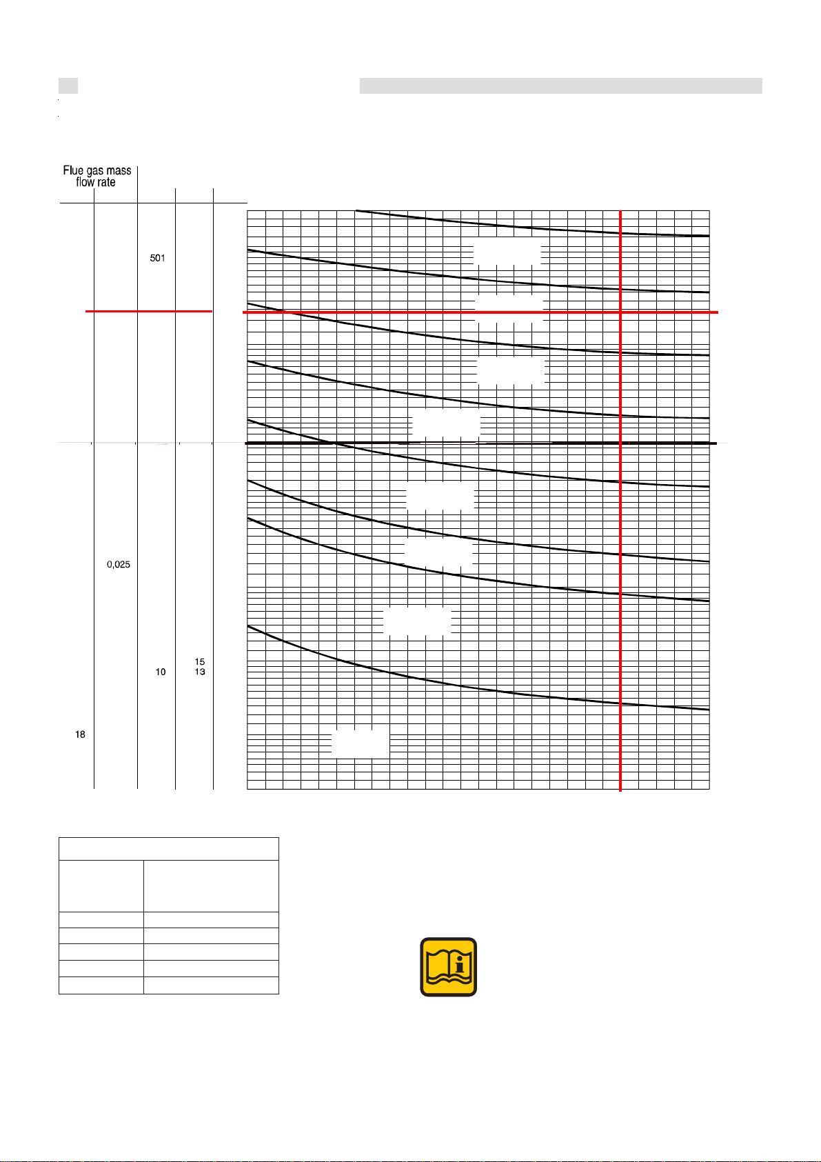
Flue gas mass flow rate
SuperModulex
440
550
660
770
900
28
Flue gas mass
flow rate (max)
kg/h
693
866
1040
1213
1386
Example:
SUPERMODULEX 660
Flue gas mass flow rate = 1040 Km/h
Chimney height = 25 m
Chimney connection Ø = 315 mm
NOTE:
the diagram provides indicative
value
g
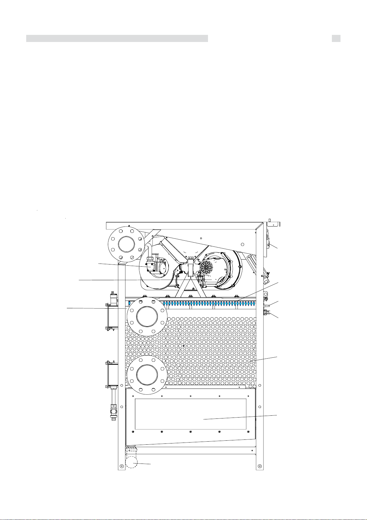
3.20 - BOILER OPERATION
Instructions for the installer
The MODULEX EXT is made of inter-linked modules; each
module is made of:
- Combustion Chamber
- Burner
- Fan
- Gas valve
- Local NTC ((Negative Temperature Coefficient) sensor
(checks the flow temperature of each aluminium section)
- BMM (Burner Modular Manager)
- High Limit thermostat
- Ignition electrode
- Ionization electrode
- Air pressure switch
A module is able to supply a maximum power of 110 kW. So,
for instance, a boiler model 440 is constituted by 4 modules.
Each module has its temperature sensor NTC - Negative
T emperatures Coef ficient - that locally checks the temperature
of every single module.
The flow temperature at the boiler outlet and the return
temperature at the boiler inlet are controlled by global NTC
temperature sensors.
Gas valve
In case of more heat request by heating or DHW systems, the
boiler starts up and water will be heated by the aluminium
boiler body
Then the boiler pump will send the water to the mixing bottle
and from here to the radiators, according to the heating
system chosen.
The combustion air is supplied by fans which take it from the
boiler room. The combustion air is then pushed into the premixing chamber through a diaphragm.
Beyond the diaphragm, the air mixes with gas and such
mixture, passing through the non-return valve, is sent to the
burner.
Then, on leaving the burner surface, the air/gas mixture ignites
electrically and the resulting combustion gases, after being
transported (and cooled) through finned sections, enter the
condensate collecting manifold and then are evacuated
through the chimney.
Control
Panel
Fan
Combustion
Chamber
Burner
Ionization
electrode
H.L.
Thermostat
Thermic
element
Condensate
collectin
tray smoke
manifold
Siphon
29

Instructions for the installer
4
When there is a heat request from the E8 controller or from a
BCM (Boiler Cascade Manager), the E8 or BCM calculates
the necessary output according to the difference between the
set temperature (or the temperature calculated by the outer
compensator) and the global flow temperature. The number
of thermal elements (each thermal element represents a maximum input of 110 kW) x 100% determines the maximum
input expressed in %.
When the input has been determined, the boiler pump (not
supplied by Unical) is set up and the fan of one thermal element is set in motion at starting speed. The gas valve opens
and ignition is to occur within 5 sec. When the ionisation electrode detects the flame, the thermal element starts operating.
Subsequently other thermal elements are likely to start in the
same way. One of the operation principles for this boiler is
letting as many burners as possible operate simultaneously
at minimum load to reach the maximum efficiency.
For example, if a 4 thermal element boiler is requested to
operate at its max input, this shall be 400% i.e. :
110 kW x 4 thermal elements = 440 kW = 400%.
If it is requested to operate at 200% input, thanks to the input
sharing system on the highest number of thermal elements,
each thermal element will operate at 50% output i.e. :
200% : 4 moduli = 50 %
corrispondente a 100 kW totali
ossia 25 kW per ciascun modulo.
Such principle provides clearly efficiencies much higher than
those obtained in traditional groups of small boilers installed
in cascade.
When the input shared on each thermal element is less than
12 kW, one thermal element after the other is automatically
excluded and the remaining input is shared on thermal
elements having the smallest number of operation hours (by
the automatic operation-time calculating system).
Modulation, i.e. input reduction, is based on the difference
between the set temperature (or the temperature calculated
by the outer compensator) and the global flow temperature.
When no ignition occurs, the ignition device repeats two more
times the ignition sequence and then puts to lock out position
the thermal element concerned.
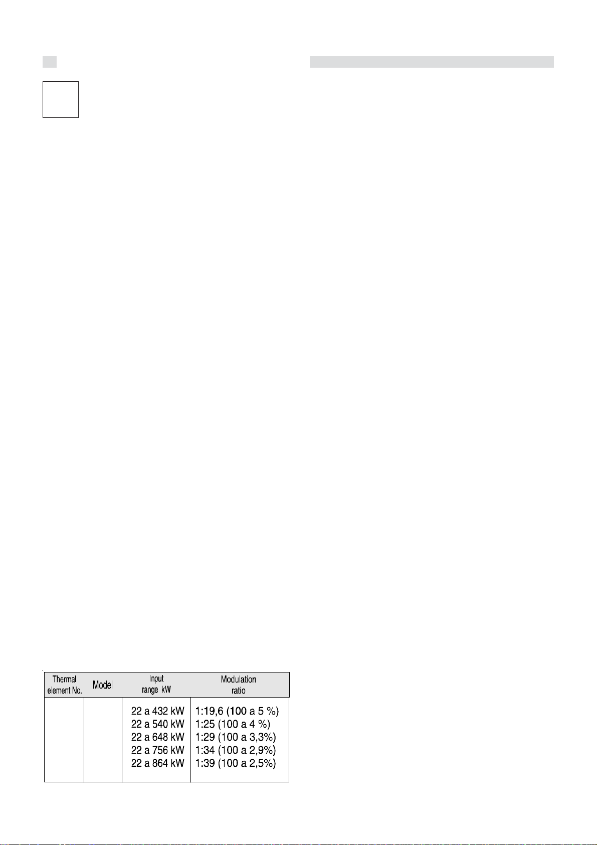
kW
% (p.c.i.)
109,6
109
104
100
4 thermal elements of 50 kW each working
at 50% of the output give = 100 kW = (200%),
i.e. 25 kW / thermal element
60
55
50
45
40
35
30
25
20
15
10
5
0
1 thermal
elemets
50 % = 54 kW
1 thermal
elemets
100 % = 108 kW
(kW)
108
P
1 Thermal element (module) = 108 kW = 100%
4 Thermal elem. = 108 kW x 4 = 432 kW = 400%
400% : 200 kW = 200% : X
20
22
30
60 70 80 90 100
50
5
10
Efficiency of a thermal element working at full capacity
108 kW = 103,2 % (in condensation)
Efficiency of a thermal element working at reduced
capacity 54 kW = 106,7 % (in condesation)
Efficiency of a thermal element working at minimum
capacity 22 kW = 108,8 % (in condesation)
40
X = (432x200) : 400 = 216 kW input shared on 4
thermal elements
Input shared on 4 thermal elements : total input
All the thermal elements work in parallel at the same output, equalizing, thus, the C.H. system efficiency to the one
of the thermal element.
= 216:432 = 0,5 = 50%
30

Instructions for the installer
3.22 - ELECTRICAL CONNECTIONS
Regulations in force
The gas and water feeding pipes and the CH system pipes
cannot be used as ground plates.
Ensure that the above safety electrical requirements subsist;
in case of doubt, ask for a professionally qualified technician
to check the appliance’s electrical system.
UNICAL refuses responsibility for any damages arising from
failure to earth the boiler correctly.
It is necessary that a qualified technician verifies that the
electrical system is adequate to the appliance’s maximum
absorbed power, indicated on the data plate, verifying in
particular that the section of the system’s cables is suitable
to the appliance’s maximum absorbed power.
For the appliance’s general electrical supply the use of
adaptors, multiple sockets and/or extension cords is strictly
forbidden.
The use of any power supplied equipment implies the
observance of several fundamental rules, such as:
- Do not touch the appliance with any wet part of your body
and/or barefooted;
- Do not pull the supply cables
- Do not permit children or inexpert people to use the
appliance.
Mains electrical supply connection 230V
The electric connections of the boiler are shown in the section
named “WIRING DIAGRAMS”
A mains supply of 230 V – 50 Hz is required. The wiring to the
boiler must be in accordance with the current CEI regulations.
WARNING!
We remind you that upstream of the electrical
connection, it will be necessary to foresee a
service relay (NOT SUPPLIED) which, when
the electrical safety devices (ISPESL)
intervene, shuts down the electrical supply
to the on-off fuel valve fitted on the gas supply
circuit, but not to the boiler so as to
guarantee the running of the pump and permit
the boiler to cool down.
DANGER!
The electrical connections must be carried
out only by a qualified engineer.
Before carrying out the connections or any
other operation on the electrical parts,
always switch off and disconnect the
electricity supply and ensure yourself that it
cannot be accidentally turned on.
It is necessary to fit a double pole switch on the electrical
supply line, having a 3 mm contact separation in both poles,
in an easy accessible position in order to make quick and
safe the servicing operations.
A
The boiler electrical supply (230 V – 50 Hz – single phase) is
to be done directly on the three pole plug supplied with the
boiler.
WARNING!
230 V cables shall be separated from 24 V
ones, using the two plastic conduits supplied
within the boiler casing L.H. side panel.
31
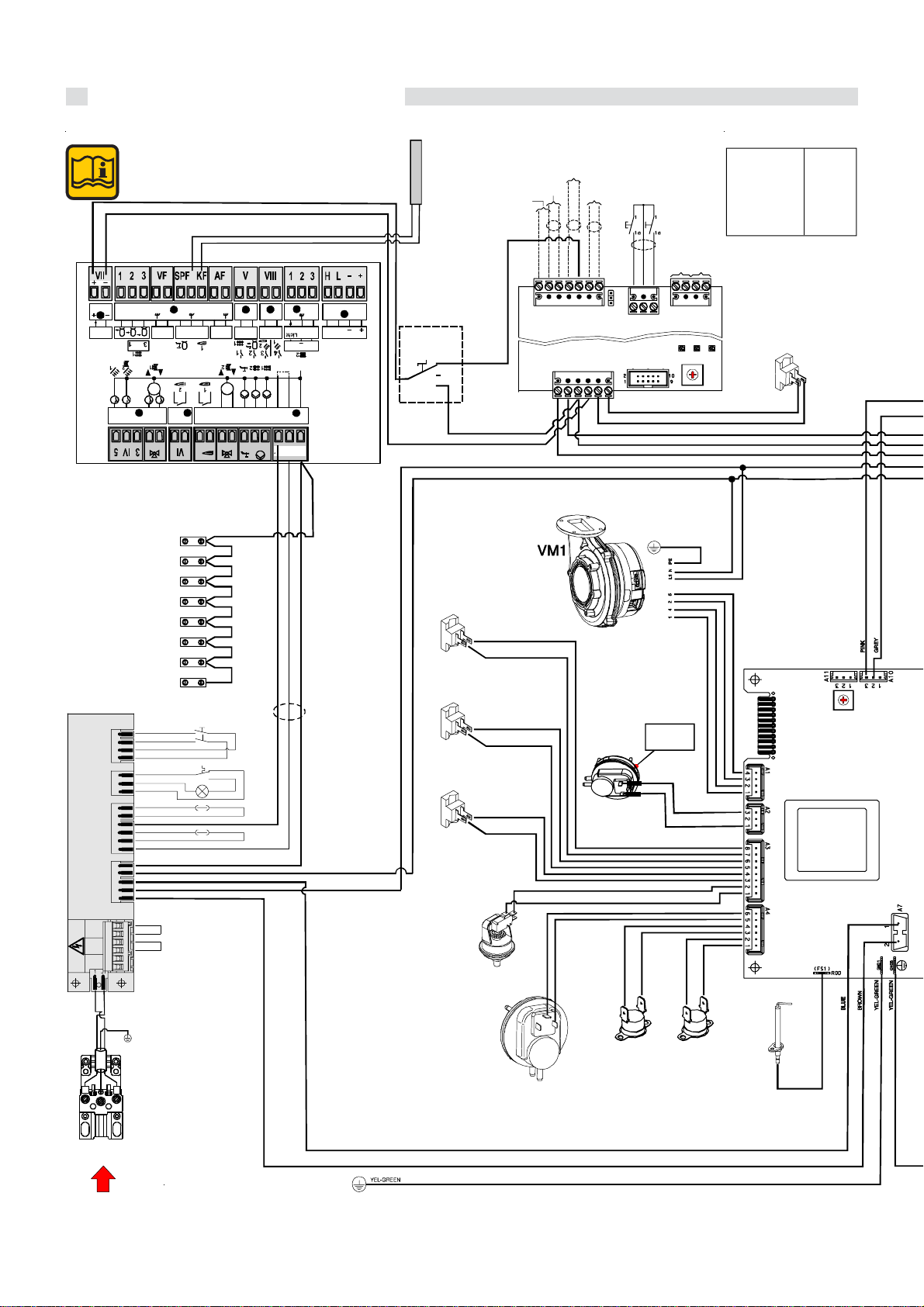
Instructions for the installer
3.23 - FUNCTIONAL WIRING DIAGRAM
Note: The pictures shown on the
actual wiring diagram, is purely
indicative.
PINK
GREY
12345678910
12
VII
0-10 V
eBUS
FA
n
4
CONTROL E8
J21
J3
1
J4
1
J3
1
A
B
NL1
VT
1
BLUE
BROWN
I
F6 F5 F3 F2 F1
VF
FBR
T3 T 4
M
21 3
A7
A8 A9 A10 A11
IV
VI
12
12345
CONNECTION
WIRE NEUTRAL (N)
M2
(IG1)
(IG2)
BLACK
BLACK
5L
C
1b 1a
BROWN
BLUE
BROWN
BLUE
BLACK
BLUE
BROWN
BROWN
RED
BLACK
BLACK
ORANGE
BROWN
BLUE
BLUE
BLUE
BROWN
BROWN
J6
F9 F8
AF KF / SPF
T1 T2
BLUE
BLUE
BLUE
BLUE
BLUE
BLUE
BLUE
BLUE
BLUE
BLUE
BLUE
BLUE
BLUE
BLUE
BLUE
4L
1N2N
2
RED
1
1
12
V
F12 F1 1
VF
SPF
M
67891012345
12 1NL1L1
IG
TLG
LTLG
F10A
F6.3A
23
2
1
III
VIII
F14 F13
0-10 V
PT1000
1
NL1L1’
A1 A2 A3 A4 A5 A6
II
BLUE
BROWN
BLACK
34
12
IX
F17 F1 5
LH
IMP
BUS
3
FBR
BLUE
KF
Choose set point value as indicated
in the table * (IF NECESSARY) and
insert resistence between Y2 (6-7).
SE8/BCM
I
1b
1
O
1a
II
SR
SRR
SR1
BROWN
PG
WHITE
EMERGENCY
SET POINT
BLACK
WHITE
RED
RED
BLACK
WHITE
(1)
CON TROL
MODULATION
(*)
BROWN
WHITE
(3)
(3)
PUMP
( - )
BROWN
eBUS
remote
(Cascade
manager)
0-10 V
Y2
+ 24 V
123
RED
WHITE
(1)
(*)
Ω
Ω
Ω
Ω
SMG
Set point
82°C
71
°C
60
°C
49
°C
38
°C
27
°C
3
2
4
1
5
0
6
9
7
8
1° Module
Ext sens
open
PUMP
BOILER CIRCUIT
123Y44
3
SW1
100 K
K
47
K
22
10 K
Short circuit
RESET
INSERT
BCM
WHITE
PF
PR
BROWN
3
BCM
IG
BLACK
RED
12
Y3
A1
ALIM.
On board
1° module
SIGNAL
ALARM
DL1 DL2 DL3
GIA/VER
BLU (N)
MARRONE (L1)
230V
NERO (-)
BLU (TACHO)
MARRONE (PWM)
ARANCIO +
RIL./REG.
of
0
1
9
2
8
7
4
6
5
PLC /
BMS
Modbus - B
Modbus - A
( - )
( + )
3
12
4567
Jp1
eBUS -
eBUS +
Y1
456
WHITE
BLACK
BROWN
1 (nc)
(c 3 )
MARRONE
BIANCO
LIGHT BLUE
LIGHT BLUE
LIGHT BLUE
LIGHT BLUE
N
MAIN SUPPLY
230 V - 50Hz
32
TLTL1
L1
PV1
WHITE
E.RIL.1
E.ACC 1..8
Ignit ion e lectrode
E.RIL 1..8
Ionization electrode
IG
Main switch
KF
Global Flow Temperature Sensor E8
LTGL
Warning lampe for the General Limit Thermostat
PF
Smoke pressure switch
PG
Minimum Gas pressure swich
Fan pressure swich
PV 1..8
Condensate level sensor
SL
Sonda Mandata Globale BCM
SMG
SR
Flow NTC Temperature sensor
SR 1..8
Local Flow NTC Te mp er ature sensor
SRR
Global Return NTC Temperature sensor
TL
High limit thermostat
TL 1..8
TLG
VG 1....8
TRA. ACC 1..8
VM 1..8
Local High limit thermostat
Global High limit thermostat
Gas Valve
Ignition Transformer
Modula t in g Fan

Instructions for the installer
V
1° MODULE
VM (A)
12345
ST 2
123
N
L1
BLUE
BROWN
YEL-GREEN
BROWN
YEL-GREEN
LIGHT BLUE
BROWN
BLUE
VM (A)
12345
ST 2
123
N
L1
YEL-GREEN
BLUE
BROWN
FILTER
BLACK
BLUE
BLACK
BLUE
BLUE
BLACK
( )
END MODULE
ST 2
123
L1
FILTER
BLACK
BLUE
BROWN
M (A)
YEL-GREEN
12345
N
BLUE
3° - 8° MODULES
YEL-GREEN
BLUE(N)
BROWN (L1 )
ALIM.
230V
BLACK (- )
BLUE (TACHO)
BROWN (PWM)
ORANGE +
RIL./REG.
PINK
GREY
PINK
RED
BROWN
BLACK
GREY
+ 24 V
eBUS +
Connection
With BCM
BLUE
BROWN
BLUE
BROWN
BLUE
BROWN
eBUS -
E.ACC.1
VG1
RED
SR2...SR7
TR.ACC.1
SL
On board
of
2° module
3
2
4
1
5
0
6
9
7
8
WHITE
WHITE
BROWN
WHITE
ORANGE
ORANGE
WHITE
BROWN
(3)
(1)
LIGHT BLUE
LIGHT BLUE
2° - 8° Modules
BLUE
BROWN
BLUE
BROWN
BLUE
BROWN
BROWN
VG2...VG8
E.ACC.2...E.ACC.8
RED
BLUE
TR.ACC.2...TR.ACC.8
TL2...TL8
PV1
WHITE
E.RIL.2...E.RIL8
Module 1
(Pos 0)
Setting of
modules selectors
Module 2
(Pos 1)
3
2
4
1
5
0
6
9
7
8
Module 3
(Pos 2)
3
2
4
1
5
0
6
9
7
8
Module 4
(Pos 3)
3
2
4
1
5
0
6
9
7
8
Module 5
(Pos 4)
3
2
4
1
5
0
6
9
7
8
Module 6
(Pos 5)
3
2
4
1
5
0
6
9
7
8
Module 7
(Pos 6)
3
2
4
1
5
0
6
9
7
8
Module 8
(Pos 7)
3
2
4
1
5
0
6
9
7
8
3
2
4
1
5
0
6
9
7
8
3° - 8° MODULES
33

Instructions for the installer
V
V
V
V
V
V
3.24 - WIRING DIAGRAM FOR CONNECTIONS AND MANAGING
On the back side of the E8 regulator there are two terminal
blocks, of which one is for the mains (230 V) connections and
the other one is for the low tension connections.
Power supply
BROWN
BLUE
Power
NL1L112 1
terminal
block
II
The main controls, necessary for the C.H. system management and for the boiler control, as well some components
which are part of the boiler house, must be connected to the
terminal blocks.
BLACK
67891012345
A1 A2 A3 A4 A5 A6
12
I
A7
M
12345
IV
A8 A9 A10 A11
21 3
M
4
Sensor
terminal
block
Power terminal assignments
Terminal II
NL1L1’
T1 T2
II
A1 A2 A3 A4 A5 A6
67891012345
M
II
NL1L112 1
N:
Neutral conductor, mains
Power supply, unit
L1:
L2:
Power supply to relay
:
heating circuit pump HK 1
:
heating circuit pump HK 2
:
Storage tank charging pump
:
Mixer open, heating circuit 2
:
Mixer closed, heating circuit 2
50 Hz 230 V
BUS
LH
IX
12
34
N
FBR
3
IMP
0-10 V
F17 F15
III
23
L1 L1’
1
PT1000
F14 F13
1
T1 T2
T3 T4
SPF
F12 F11
III
1
2
VF
V
12
AF KF / SPF
F9 F8 F6 F5 F3 F2 F1
F
I
FBR
n
eBUS
0-10 V
12345678910
GREY
From BCM
FA
II
12
PINK
Te rminal VI
T3 T4
I
A7
12
Terminal IV
A8 A9
M
n
34
12345
21 3
I
A10 A11
4
VI
IV
:
Mixer open, heating circuit 1
:
Mixer closed, heating circuit 1
Multifunction relay
Multifunction relayRecycle pump /
1
2
3
4

Sensor terminal assignments
Instructions for the installer
Terminal VII
12
VII
FA
eBUS
0-10 V
Terminal I
12345678910
FBR
VF
I
F9 F8 F6 F5 F3 F2 F1
AF KF / SPF
Terminal V
12
VF
V
SPF
F12 F11
T e r m inal VIII
12
VIII
PT1000
F14 F 13
VII
Connection to BCM
Pin 1:
Pin 2:
I
VF
Pin 4:
VF
Pin 5:
SPF
Pin 6:
SPF
Pin 7:
KF
Pin 8:
AF
Pin 9:
AF
Pin 10:
V
VF
SPF
F13
F14
eBUS (FA) or 0-10V output
(Ground)
Buffer storage tank low sensor
Buf. stor. tank middle sensor / FBR heat. circ. 1 (room sensor)
Buf. stor. tank top sensor / FBR heat. circ. 1 (set value)
Flow sensor, heating circuit 2 (ground)
Flow sensor, heating circuit 2
Storage tank sensor
Storage tank and boiler sensor (ground)
Boiler sensor
Outdoor sensor
Outdoor sensor (ground)
Pin 1: Flow sensor heating circuit 1 / sensor multifunction 1
Pin 2: Service water low sensor / sensor multifunction 2
Pin 1: Sensor HS2 / Solar 2 / Multifuncti on relay 3
Pin 2: Sensor Solar 1 / Sensor multifunction relay 4
T e r m in a l III
1
0-10 V
FBR
3
III
IMP
F17 F15
Morsetto IX
1234
LH
IX
BUS
III
123
F15
Pin 1:
Pin 2:
F17
Pin 3: FBR heating circuit 2 (set value) / Pulse counter for
For connection to remote control devices
IX
H
CAN Bus Pin 1 = H (Data)
CAN Bus Pin 2 = L (Data)
L
CAN Bus Pin 3 = - (ground, Gnd)
-
CAN Bus Pin 4 = + (12V supply)
+
FBR heating circuit 2 (room sensor) / 0-10V IN / Light
FBR heating circuit 2 (ground)
35

Instructions for the installer
V
V
V
3.25 - INSTALLATION EXAMPLES (functional wiring and connections description)
INSTALLATION OF A BOILER WITH CONNECTION TO A DIRECT HEATING ZONE
Heating Circuit 1
AF
(9-10) outdoor sensor
(4) Pump heating circuit 1
(4) Collector pump
VF
*
VF
VF
1
AF
F
(1) Flow sensor heating circuit 1
I
(10) Ground outdoor sensor
10
This sensor can also remain unused
*
Outside
Sensor
Safety devices kit
Mixing Header
1-2
123Y44
BCM
Primary
system pump
Filter
INSTALLATION OF A BOILER WITH CONNECTION TO TWO DIRECT HEATING ZONES + D.H.W. PRODUCTION
This sensor can also remain unused
*
F
I
10
F Ric. C
(1) Flow sensor heating circuit 1
(10) Ground outdoor sensor
Heating Circuit 2
4
n
SPF
VF
**
VF
Heating Circuit 1
VF
*
VF
VF
F
(4-5) Flow sensor heating circuit 2
not necessary to active 2° circuit
**
SPF
(6-7) Storage tank sensor
(9-10) outdoor sensor
AF
(4) Pump heating circuit 1
(5) Pump heating circuit 2
(6) Cylinder charging pump
(5) Re-circulation pump storage tank
n
(4) Collector pump
2
1
Mixing Header
AF
Outside
Sensor
Safety devices kit
3
Primary
system pump
Filter
36

Instructions for the installer
g
g
y
V
V
V
V
INSTALLATION OF A BOILER WITH CONNECTION TO ONE MIXED AND ONE DIRECT HEATING ZONES + D.H.W. PROD.
This sensor can also remain unused
*
I
F Ric.
F
(1) Flow sensor heating circuit 1
(10) Ground outdoor sensor
10
C
Heating Circuit 2
4
n
SPF
Heating Circuit 1
F
(4-5) Flow sensor heating circuit 2
SPF
(6-7) Storage tank sensor
AF
(9-10) outdoor sensor
(4) Pump heating circuit 1
(5) Pump heating circuit 2
(6) Cylinder charging pump
(7) Mixer motor heating circuit 2 OPEN
(8) Mixer motor heating circuit 2 CLOSE
(5) Re-circulation pump storage tank
n
(4) Collector pump
Outside
Sensor
Safety devices kit
3
Filter
Primary
system pump
VF
VFVF
*
VF
VF
2
1
AF
Mixing Header
INSTALLATION OF A BOILER WITH CONNECTION TO TWO MIXED ZONES + D.H.W. PRODUCTION
necessary for mixing valve control
*
F
(1) Flow sensor heating circuit 1
I
(10) Ground outdoor sensor
10
F Ric.
C
Heatin
4
Circuit 2
Heatin
Circuit 1
F
(4-5) Flow sensor heating circuit 2
SPF
(6-7) Storage tank sensor
AF
(9-10) outdoor sensor
(4) Pump heating circuit 1
(5) Pump heating circuit 2
(6) Cylinder charging pump
n
SPF
(7) Mixer motor heating circuit 2 OPEN
(8) Mixer motor heating circuit 2 CLOSE
(1) Mixer motor heating circuit 1 OPEN
(2) Mixer motor heating circuit 1CLOSE
VF
VF
2
VF
*
VF
VF
1
Mixing Header
(5) Re-circulation pump storage tank
n
(4) Collector pump
AF
Outside
Sensor
devices kit
Safet
3
Filter
Primary
system pump
37

Instructions for the installer
V
V
INSTALLATION OF A BOILER WITH CONNECTION TO TWO MIXED ZONES + D.H.W. PRODUCTION BY SOLAR PANELS
necessary for mixing valve control
F
(4-5) Flow sensor heating circuit 2
SPF
(6-7) Storage tank sensor
AF
(9-10) outdoor sensor
(4) Pump heating circuit 1
(5) Pump heating circuit 2
(6) Cylinder charging pump
(7) Mixer motor heating circuit 2 OPEN
(8) Mixer motor heating circuit 2 CLOSE
(1) Mixer motor heating circuit 1 OPEN
(2) Mixer motor heating circuit 1CLOSE
(5) Re-circulation pump storage tank
n
(4) Collector pump
*
F
(1) Flow sensor heating circuit 1
I
(10) Ground outdoor sensor
10
V
(2) Hot water tank low / Multifunction relay sensor 2
PT1000
(2) PT1000 sensor solar 1 / Multifunction relay sensor 4
PT1000
F14
2+
4
5
A11
F12
2+
C
F
SPF
Heating Circuit 2
VF
VF
2
Heating Circuit 1
VF
*
VF
VF
1
AF
Outside
Sensor
Safety device s kit
Mixing Header
3
Primary
system pump
Filter
For the connection to a solar installation it is
necessary to change some parameters. See
Table:
Expert AREA ⇒ Level SOLAR / MF ⇒ MF 4
FUNCTION = ‘’23’’
38

Instructions for the installer
g
y
y
V
V
INSTALLATION OF A BOILER WITH CONNECTION TO TWO MIXED ZONES + D.H.W. PRODUCTION
F Ric.
C
Circuit 1
Heating Circuit 2
4
n
SPF
Heatin
KF
AF
Outside
Sensor
VFVF
VF
2
*
VF
VF
1
Mixing Header
Boiler
Sensor
Primary
system pump
Primary
system pump
Safet
Safet
devices kit
3
Filtro
devices kit
3
Filter
Remote
E8
Master
Slave 1
Slave 2
ATTENTION!
In this type of installation it is necessary to adjust,
in the E8 controller, the parameter BUS-ID HS.
The external regulator E8 (MASTER) has to be set to:
----,
the boiler regulators E8 (SLAVES) have to be set to:
01 to 08.
Connections on to the MASTER controller
The connections of the secondary circuit have to be done on
to the MASTER controller.
F
(4-5) Flow sensor heating circuit 2 (optional)
SPF
(6-7) Storage tank sensor
(7-8) Cascade global sensor
KF
(9-10) outdoor sensor
AF
(4) Pump heating circuit 1
(5) Pump heating circuit 2
(6) Cylinder charging pump
(7) Mixer motor heating circuit 2 OPEN
(8) Mixer motor heating circuit 2 CLOSE
(1) Mixer motor heating circuit 1 OPEN
(2) Mixer motor heating circuit 1CLOSE
(5) Re-circulation pump storage tank
n
necessary for mixing valve control
*
F
(1) Flow sensor heating circuit 1
I
(10) Ground outdoor sensor
10
39

Instructions for the installer
3.26 - CASCADE MANAGER (BCM)
Application:
The BCM completes the range of functions offered by the
Modulex boilers:
- ON/OFF alarm control
- Control of a modulating header pump with the aim of
significantly increasing efficiency at low heating loads.
- Possibility of integrating the Modulex boilers in PLC
controlled boiler plants
- Thanks to LonWorks/Modbus protocol converters been
readily available also opens the road to installing
Modulex boilers in the most advanced Building
Automation Systems.
Features:
The BCM can be connected to the automation system of
a boiler plant via one of its interfaces:
- eBUS: for connection to the series of E8 heating
controllers or to an additional BCM
- Modbus: application in PLC controlled boiler plants
The communication protocols enable complete system
management:
- Control of heating request: temperature set point and
modulation level
- Monitoring of boiler operation and temperature status
- Alarm control
- Functional parameters setting
Special functions
Emergency: it avoids system shutdown caused by an
interruption in communication with the boiler plant’s
automation system:
- Input for “Constant setpoint” request: 55°C, maximum
output 50%
- Alarm reset input
- Alarm relay signal
Monitor:
a BCM connected to a group of heating generators
managed by a E8 heating controller, automatically selects
the “monitor” mode.
In this condition the following services are supplied:
- Acquisition of all the operating data and diagnostics via
the Modbus interface.
- Control of the modulating pump
- Control of the Alarm relays and control of the header
pump
- If the E8 malfunctions, the BCM automatically resets
normal boiler operation control and can enable the
emergency function previously described.
Management of the header pump:
- Relay command for running a pump at fixed rate
- 0÷10 analogical output for control of a modulating pump
40

Instructions for the installer
Connection for boilers in a cascade arrangement managed by a external E8
SLAVE 1
BCM (modulex 1)
Y2 (3-4)
1
+ 24 V
23
eBUS eBUS +
Y1
456
BCM
A1
Y3
DL1 DL2
SW1
DL3
BCM (modulex 2)
Y2 (3-4)
123
+ 24 V
eBUS -
eBUS +
Y1
456
BCM
A1
Y3
DL1 DL2 DL3
SW1
BCM (modulex 3)
Y2 (3-4)
123
+ 24 V
eBUS -
eBUS +
Y1
456
BCM
A1
Y3
DL1 DL 2
SW1
DL3
E8
CanBUS
MASTER
1 for each cascade of boiler
- Cascade Manager
Switch ‘’C’’ (see pag. 47)
in Position II
SLAVE 2
I = BCM in series
II = Forniture Position
In this configuration,
switch ‚‘‘C‘‘ must be
positionned on II.
Y2
4567
eBUS remoto
eBUS remoto
123
Jp1
123
4
3
Y4
12
67
Y2
Jp1
eBUS remoto
45
3
eBUS remoto
12
Removed
Cascade Manager
wiring
123
4
Y4
123
Cascade Manager
612345
12NL1L1
A1 A2 A3
II
E8
612345
12NL1L1
A1 A2 A3
II
E8
V
2
SPF
F12F11
12
VIII
PT1000
F14F13
123
L1 L1’
0-10 V
III
N
FBR
31
IMP
F17 F15
1
LH
234
IX
BUS
1234
IX
LH
BUS
V
2
SPF
F12 F11
12
VIII
PT1000
F14F13
123
L1 L1’
0-10 V
III
N
FBR
31
IMP
F17 F15
1
LH
234
IX
BUS
Cascade Manager
WARNING!
In this connection the “BUS-ID HS„
parameter must be set on the E8 heating
controller
67
Y2
Jp1
eBUS remoto
45
eBUS remoto
3
12
Removed
wiring
123
4
3
Y4
12
Cascade Manager
The external E8 heating controller (MASTER) must be set
to: - - - -,
The E8 heating controllers fitted on each boiler (SLAVE)
must be set from: 01 to 08.
Dalla 1a caldaia portare il collegamento eBUS
lato HOST BCM su eBUS 2a e 3a etc. dopo aver
posizonato il selettore di questa su 0.
41
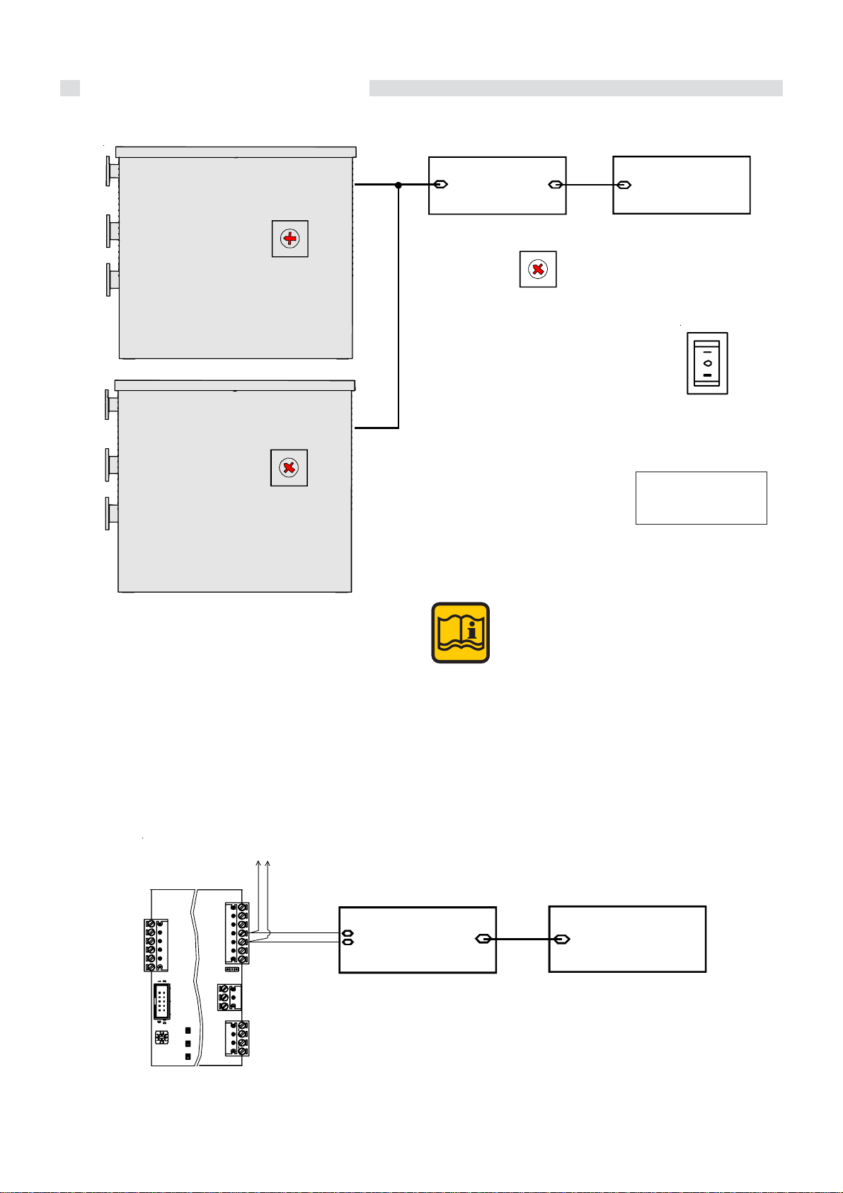
Instructions for the installer
y
Connection for boilers in a cascade arrangement connected to an external BCM optional and managed by
PLC/BMS (E8 disconnected).
SLAVE 1
BCM
(Pos 0)
3
2
1
0
9
7
8
SLAVE 2
BCM
(Pos 1)
3
2
4
1
0
9
7
8
BCM board
eBUS
4
5
6
- Cascade Manager
- System Monito r
Modbus
BCM
(Pos 1÷7)
3
2
4
1
5
0
6
9
7
8
PLC/BMS board
Modbus
- System Manager
- System Supervisor
Switch ‘’C’’ (see pag. 47)
in Position 0
(for each boilers)
I = BCM in series
II = Forniture Position
5
6
In this configuration,
switch ‚‘‘C‘‘ must be
positionned on 0.
- E8 not wired to the BUS -
SW1
1
+ 24 V
23
eBUS eBUS +
Y1
456
The applications in a cascade arrangement
managed with an additional BCM require the
correct boiler address setting (within the
cascade formation) via the BCM’s internal
SWI selector: 0....7, all different and in
sequence, (exactly as requested by the single
burner modules).
BCM (modulex 2)
Y2 (3-4)
- Cascade Manager
7
6
Y2
45
3
12
Jp1
BCM
A1
Y3
4
DL1 DL2 DL3
Y4
123
eBUS remoto
eBUS remoto
123
- System Monitor
Scheda BCM
eBUS
Modbus
- System Manager
- System Supervisor
Scheda PLC/BMS
Modbus
- System Manager
stem Supervisor
- S
42

Instructions for the installer
Connection for boilers in a cascade arrangement managed by an external PLC (E8 disconnected)
Board PLC/BMS
SLAVE 1
BCM
(Pos 0)
3
2
1
0
9
7
8
4
5
6
Modbus
1 for each c ascade of bo iler
- System Superv isor
- Cascade M anager
BCM
(Pos 1÷7)
3
2
4
1
5
0
6
9
7
8
Switch ‘’C’’ (see pag. 47)
in Position 0
(for each boilers)
1
+ 24 V
23
eBUS eBUS +
Y1
456
SLAVE 2
BCM
(Pos 1)
3
2
4
1
0
9
7
8
5
6
I = BCM in series
II = Forniture Position
In this configuration,
switch ‚‘‘C‘‘ must be
positionned on 0.
The applications in a cascade arrangement
managed with Modbus require the correct
boiler address setting (within the cascade
formation) via the BCM’s internal SWI
selector: 1....7, all different and in sequence,
(exactly as requested by the single burner
modules).
BCM (modulex 2)
Y2 (1-2)
System Supervisor
67
Y2
45
3
12
BCM
Jp1
eBUS remoto
eBUS remoto
Cascade Manager
Scheda PLC/BMS
Modbus
A1
DL1 DL2 DL3
SW1
123
Y3
4
Y4
123
43

Instructions for the installer
3.27 - CONFIGURATION WITH A:
MODULATING PUMP
he BCM board elaborates the data concerning the thermal
head (Ät between primary flow and return and supplied
heat output). When the supplied heat output diminishes,
the number of the pump’s revolutions decreases and
subsequently the hourly rate, maintaining the thermal head
practically constant. Thus obtaining a higher efficiency in
condensing mode and reducing energy costs.
The 0÷10 Volt modulation signal is preset to:
-3 for minimum speed
-10 Volt for maximum speed
These values can be changed according
to the type of pump fitted. For further
information on the 0÷10 Volt signal, please
also refer to the pump’s manual.
TERMINALS 0-10 V
INTERFACE
WILO MOD U LATING PUMP
(-)
(0 - 10 V)
+ 24 V
eBUS -
eBUS +
123
MODULATING PUMP
ALARM
3
12
123Y24567
Y1
456
Jp1
BCM
4
Y3
DL1 DL2 DL3
A1
Mains supp ly
230 V -50 Hz
N
L1
L1
3
12
Y4
SW1
N
APM
Supply
Modulating
Pump
POWER TERMINALS E8
3
4567
Y2
+ 24 V
eBUS -
eBUS +
Y1
456
123
ON-OFF PUMP
Mains supply
230 V - 50 Hz
ALARM
123
3
12
Jp1
BCM
4
Y4
Y3
DL1 DL2 DL3
A1
Mains supply
230 V - 50 Hz
N
L1
N
L1
RELAY
L
N
12
SW1
P
PUMP
44
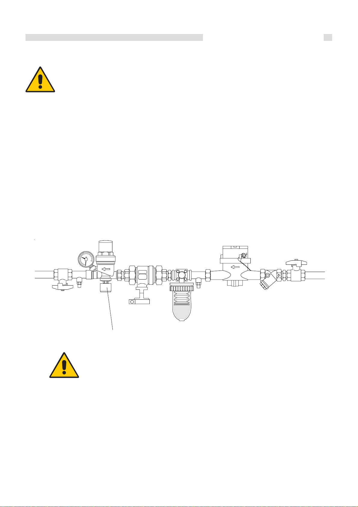
3.28 - FILLING THE SYSTEM
Instructions for the installer
Warning!
Do not mix the CH system’s water with antifreeze or anti-corrosion solutions using wrong
concentrations! It could cause damage to the
washers and could provoke noise during
normal boiler operation.
UNICAL refuses all liability for injury to persons,
animals or damage to property deriving from
not having respected the above mentioned
recommendations.
For filling-up the system a filling tap has to be foreseen on
the system return pipe.
The filling-up can also be made through the draining tap on
the boiler return manifold.
EXAMPLE OF FILLING-UP SYSTEM MANIFOLD
Never use such a tap to drain the system, since the system dirt
could gather in the boiler and compromise its operation. The
system itself shall be equipped with its own draining tap, whose
size depends on the system capacity. The application of a
filter on the return pipe to the boiler is advisable.
Filling group with PRV
IMPORT ANT NOTE
Once the system has been filled up
at the right filling pressure, the filling
group has to be closed.
45

Instructions for the installer
3.29 - BURNER ADJUSTMENT
WARNING!
All the instructions indicated below are for the
exclusive use of qualified UNICAL service
technicians or installers.
All the boilers are supplied already calibrated
and tested. If it is necessary to change the
calibration due to gas conversion or adaptation
to the mains supply system, the gas valve must
be re-calibrated. (Using service mode function)
A) REGOLAZIONE ALLA POTENZA MASSIMA
- Remove the cap of the combustion gases sampling point
- Connect a suitable C02 gas analyser to the sampling point
in the flue outlet terminal.
- Operate on a burner at maximum power, following the procedure described on page 46 ‘’sweep Function (CASCADE MAN 100%)
- Check that the C02 values are within the values indicated
in the table “Burner pressures”
- If necessary correct the value by turning the adjustment
screw “A” in a CLOCKWISE direction to decrease the value and in an ANTICLOCKWISE direction in order to increase it.
1
2
3
4
WARNING!
Remove the cap 2, fix red cap 3 to the gas
outlet. Insert the CO2 analysis probe 4 on
hole of the cap.
Measurement. remove the cap and close the
outlet exhaust smoke cap 2.
B) MINIMUM OUTPUT ADJUSTMENT
- Operate on a burner at minimum power, following the procedure described on page 46 ‘’sweep Function (CASCADE MAN 10%)
- Check that the C02 values are within the values indicated
in the table “Burner pressures”
- If necessary correct the value by turning the adjust-
ment screw “B” in a CLOCKWISE direction to increase
the value and in an ANTICLOCKWISE direction in order to decrease it.
46
MAXIMUM OUTPUT
ADJUSTMENT SCREW
MINIMUM OUTPUT
ADJUSTMENT
SCREW

Instructions for the installer
Follow this procedure also for the other burners
If the CO2 percentage is too low, check if the air and smoke
ducts are not obstructed. If they are not obstructed, check if the
burner and/or the exchanger (aluminium sections) are well
cleaned.
C) COMPLETION OF THE BASIC
ADJUSTMENTS
- Check the C0
- If necessary make the required adjustments
- Close the sampling test point in the flue outlet terminal
values at the minimum and maximum outlet
2
To ensure correct operation the C0
have to be adjusted with extreme care
values
2
respecting the values indicated in the table.
Do not force the end switches of the
adjusting screw.
In case of gas valve replacement or difficult
ignition:
Tighten the maximum adjustment screw “A”
in a clockwise direction until you arrive to
the abutting end, than slacken for 9 turns.
Verify the boiler ignition; if the boiler goes
into lockout slacken the screw “A” again of
one turn, than retry the ignition. If the boiler
goes into lockout again, carry out the above
indicated operations until the boiler is
lighted.
At this point carry out the burner adjustment
as previously indicated.
INJECTORS – PRESSURES
Gas type Supply
MODULEX
440 - 550
660 - 770 - 900
Gas nat. (G20)
Gas nat. (G25)
Propan (G31)
pressure
(mbar)
20
25
37
Ø
Injectors
(mm)
9
9
9
Check the C0
Diaphragm
-
-
-
levels often, especially at low flow rate
2
Fan speed
min
(rpm)
1760
1760
1760
max
(rpm)
6300
6300
6300
CO2 levels (%)
max
min
9,1
9,1
10,2
9,3
8,6
10,4
Starting
power
IG
(%)
50
50
50
47

Instructions for the installer
SWEEPER MODE
Before open the operating flap
turn clock-wise Shaft encoder,
to symbol
O
pen the operating flap,
displayed
DISPLAY
RELAY TEST
Turn
clok-wise
Turn
anticlok-wise
GENERAL
Press
to open
the le v e l
After
2 sec
is displayed
level
SW NO XXXX
CA SC ATA MANU
DATA/TIME
clok-wise
BOILER 01 - 00%
Turn
anticlok-wise
Press
to open
the level
Turn
SERVICE
Press
to open
the level
CHANGE PER C EN T
VALUE
TO 10 %.
BOILER 01 - 10%
VA R Y THE VALU E
PER CENT
FROM 10 % TO 100%.
BOILER 01 - 100%
The function is active for a time of 15 min,
after that the planned parameters are
restored.
All modules of the
boiler running and
working at MINIMUM
power
All modules of the
boiler running and
working at MAXIMUM
power
For the adjustment of each individual module it is
necessary to put the switch ‘’ C ‘’, in position I, as
shown in the figure. In this way all the modules
are switched OFF and the first module is ignited.
T o pass to the following modules (after the previous
one has been switched OFF) repeat the step 0 - 1
of the switch ‘’ C’ as shown in figure.
C
BCM
48
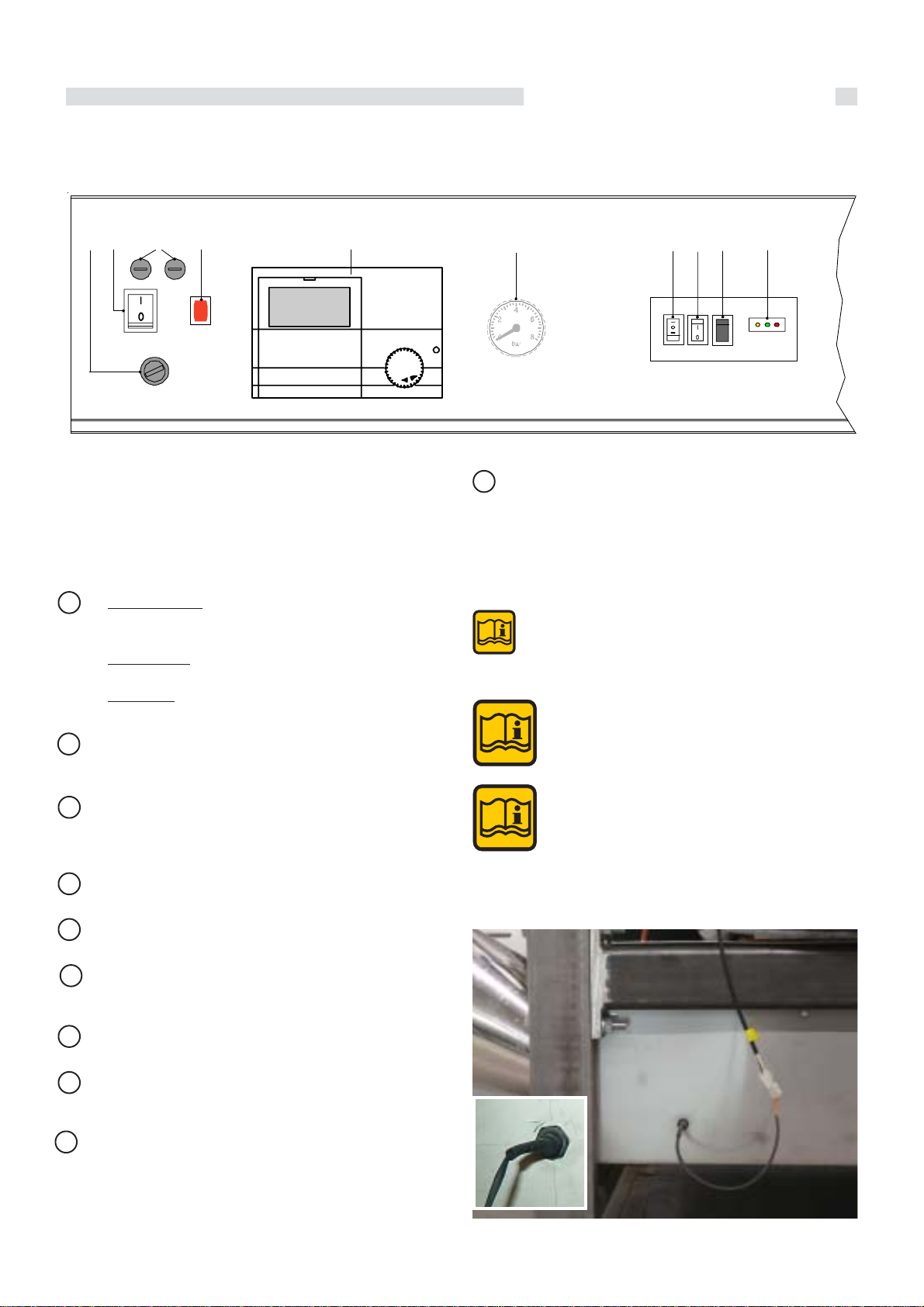
3.30 - EMERGENCY FUNCTIONS
Instructions for the installer
I
The BCM It avoids system shutdown in case the main
boiler plant’s system E8 5064 management is out of
use.
A YELLOW LED = Blinking
(communication between BMM and BCM) OK
GREEN LED = ON (Active Pump)
2
1
EFGH
D
L Change-over Series/Parallel
0 = Emergency is active or the control is
managed by PLC or BMS
I = Series connection (the cascade is
managed by the BCM,
II = Parallel connection condition of for
niture
C B
AL
BCM
RED LED = ON (Failure code detected)
B Enables burner reset in case of lock-out
C In position I the plant will operate when reque
sted at “CONSTANT SETPOINT”: 70°C –
Max heat output 50%
D Idrometer (optional)
E Control Panel E8
F Warning lamp of the thermostatic lockout
from TLG
G Fuse: 1 = 6.3 A 2 = 10 A
H Main Switch
I TLG General Limit Thermostat: when it acts, it
cuts the power supply to the boiler, the
warning lamp E lights. To reset, remove the
cap and push the reset button.
Note: The switches are positioned under
the front panel.
Note: The emergency function enables
the boiler’s burners to fire only at 50%
and at 50°C in system return. All the
system’s heating loads, including the
header pump, must be controlled
manually.
Condensate level sensor position
49

Instructions for the installer
3.31 INITIAL LIGHTING
PRELIMIARY CHECKS
The first ignition must be carried out by a
qualified technician. Failure to do so could
cause injury to persons, animals or damage
to property. UNICAL shall not be held liable
for any injury and/or damage.
Before lighting the boiler check that:
- the boiler installation has been carried out in accordance
with the specific Standards.
- the combustion air inlet and the discharge of the products
of combustion occur in the correct way in accordance to
the specific Standards in force;
- the gas supply system is correctly dimensioned for the boiler’s output;
- the boiler’s electrical supply is 230 V - 50 Hz;
- the system has been filled with water (pressure registered
on the gauge 0,8/1 bar with pump not running);
- any of the system’s on-off valves are open;
- the mains supply gas corresponds to the one which the
boiler has been calibrated for: otherwise convert the boiler
to use the available gas (refer to section: “GAS CONVERSION”); this operation must be carried out by a qualified
technician in compliance to the regulations in force;
- the gas supply cock is open;
- there are no gas leaks;
- the external mains supply switch is on;
- the boiler system’s safety valve is not blocked and that it is
connected to the sewage system;
- the condensate drain siphon has been filled with water
and that it is connected to the sewage system;
- there are no water leaks;
- all the necessary ventilation conditions and minimum clearance distances are guaranteed for subsequent servicing in case the boiler is sited in a cupboard compartment.
Information to be passed on to the user
The user of the appliance must be instructed on the use
and operation of his boiler and in particular detail:
- Hand over to the end user the booklet: “USER’S INSTRUCTIONS GUIDE”, as well as all the other literature relative to
the appliance and placed in the envelope contained in the
packaging. The
literature for any future reference.
- Inform The user of the importance of the air vents and of
the flue outlet system, stressing the fact that absolutely no
alteration can be made.
- Inform the user regarding the control of the system’s water
pressure and how to restore it to the correct value.
- Explain and demonstrate to The user the correct function
and adjustment of the temperature, thermostats and radiators for the economic use of the system.
- Remind the user that in order to comply to the regulations
in force the boiler has to be inspected and serviced regularly as indicated by the manufacturer.
- If the appliance is sold or transferred to another owner or if
the present user moves home and leaves the appliance
installed, ensure yourself that the manual always follows
the appliance so that it can be consulted by the new owner
and/or installer.
user of the appliance must retain this
50
DANGER!
Before firing the appliance fill up the siphon
through the filling hole and check the correct
drainage of the condensate.
If the appliance is used with the condensate
drain siphon empty this could cause
poisoning caused by the leakage of the flue
gasses.

4
Servicing schedule
SERVICING
SCHEDULE
To ensure the continued safe and efficient
operation of the boiler it is highly
recommended that it is checked at regular
intervals and serviced when necessary , and
that only original spare parts are used.
The law in force states that the boiler must
be serviced annually .
If the boiler is not checked and serviced when
necessary it could cause material and
personal damages.
For this reason UNICAL recommends that a servicing contract should be made with a heating installer.
The regular inspection is useful to determine the actual state
of an appliance and to compare it with an optimum state. This
is achieved through measurement, control and observation.
The service is necessary to eliminate eventual deviations of
the actual state from the optimum state. This is normally done
through the cleaning, the parameters setting and the eventual replacement of single components subject to mechanical
wear.
The frequency of servicing will be determined by the service
engineer and will depend on appliance’s state of condition.
INSTRUCTIONS FOR SERVICING
To ensure a long life to all your boiler
components and in order not to alter the
conditions of the approved product only
original UNICAL spare parts must be used.
After having carried out all the necessary maintenance, always
follow these steps:
• Switch OFF the main switch
• Isolate the boiler from mains via a device having, at least,
a 3 mm in the switch contacts (e.g.: safety devices or power
switches) and make sure it cannot be switched ON accidentally.
• Switch off the gas gate valve upstream the boiler.
- If necessary , and in function of the type of work to be carried
out, close any on-off valves fitted on the CH flow and return
pipes, as well as the cold inlet valve.
- Remove the appliance’s front panel.
After maintenance works have been finished, follow the next
steps:
- Open the CH flow and return valves as well as the cold
inlet valve (if previously closed),
- Purge and, if necessary, proceed with restoring the heating
system’s pressure until a pressure of 0,8/1 bar is reached.
- Open the on-off gas valve.
- Reconnect the appliance to the electrical supply and
switch on the mains electrical supply.
- Test for gas soundness, on the gas side and on the water
side.
- Replace the appliance’s front panel.
.
T ABLE OF THE RESISTANCE VALUES IN FUNCTION OF THE HEATING SENSOR (SR) AND RETURN HEATING SENSOR
TEMPERA TURE (SRR)
T°C0123456789
0 32755 31137 29607 28161 26795 25502 24278 23121 22025 20987
10 20003 19072 18189 17351 16557 15803 15088 14410 13765 13153
20 12571 12019 11493 10994 10519 10067 9636 9227 8837 8466
30 8112 7775 7454 7147 6855 6577 6311 6057 5815 5584
40 5363 5152 4951 4758 4574 4398 4230 4069 3915 3768
50 3627 3491 3362 3238 3119 3006 2897 2792 2692 2596
60 2504 2415 2330 2249 2171 2096 2023 1954 1888 1824
70 1762 1703 1646 1592 1539 1488 1440 1393 1348 1304
80 1263 1222 1183 1146 1110 1075 1042 1010 979 949
90 920 892 865 839 814 790 766 744 722 701
Relation between the temperature (°C) and the nom.
resistance (Ohm) of the heating sensor SR and the return
heating sensor SRR.
Example: At 25°C, the nominal resistance is 10067 Ohm
At 90°C, the nominal resistance is 920 Ohm
51

Servicing schedule
We recommend that periodical service is made
by qualified technical personnel according to
the frequency stated by national rules in force.
As much as the dust present in the air will be sucked inside
the combustion chamber, the smoke side resistance will
increase, which, finally, will result in a reduced heat input
(and consequently a reduced output).
efore cleaning the boiler body sections, check the boiler input
and the CO2 percentage (see 3.24).
Note! A reduction of the input can be caused
by the obstruction of the evacuation duct or
of the air intake. Check, first of all, that this
is not the reason.
If the actual input (with the correct CO2) is within 5% of the
value shown in the chapter 3.24, the boiler does not need to
be cleaned.The operation then, can be limited to the cleaning
of the siphon.
st
1
Phase - Disassembly
• Switch off power and gas supply and ascertain the gas
cock is well closed.
• Remove
- Act on the two closing hinges (on both sides) to remo-
ve the cover
- all panels of the casing.
- Rotate the screw shown to lift the cover cap
- Remove the screws panel left, right and back side.
- Rimuovere le 2 viti di fissaggio coperchio
52

Servicing schedule
- Remove the red silicone pipe and then the fans room
• Screws on thermal elements
A
- Sganciare la molla di fissaggio camera ventilatori
(lato destro/sinistro).
- Remove the screws “A”, fixing the burner covers,
(with a 13 mm socket or open wrengh)
53

Servicing schedule
C
- move up the burners block (Front)
- move up the rear burner block and remove the 2 pins with
5 mm hex key to reach the holes ‘’C’’ (left and right).
- Remove gas fittings from the gas manifold with flat key
36 mm.
- Remove the screws gas collector (left and right side).
- Remove the four screws with a 36 mm socket wrengh,
then the gas flange
54

2nd phase – Cleaning
• Remove from their seat the sealing gaskets and the burners.
• Make a dry-cleaning by blowing compressed air on the “
flame” side of the burner
• Visually check the condition of the welds of the metal spon-
ge burner.
The burner sealing gaskets, must be replaced at each cleaning of the burner.
Servicing schedule
Compressed air
• Wash, with a water jet, the combustion chamber: pay attention to not to wet the electrical wiring. During this operation
ascertain that the condensate evacuation pipe is always
free, so that the water cannot come out from the tray.
• Blow with compressed air in the combustion chamber, in
between the sections, so that all dirty parts are removed
from the aluminum protrusions.
• Once the cast aluminum sections have been washed, make
sure the condensate evacuation siphon is free: if necessary clean it.
• Inspect the flue duct and the smoke chamber.
3rd phase – Reassembly
• After cleaning the body and / or burners reposition the
burners in their seats
• Replace the NEW burner sealing gaskets
Reassemble all the components previously
removed by following the reverse order
to tighten the screws of the mixer / fans to the
body, with torque of 13 Nm
CAUTION
FOR EACH OPERA TION OF MAINTENANCE
‘MUST BE REPLACED THE GASCKETS FOR
EACH BURNER.
Spare code:
95251632 - GASKETS KIT for BURNER
MODULEX EXT 348-900 (5 pz.)
95262961 - BURNER KIT MODULEX EXT 348-900
• Before starting the boiler ascertain that the condensate siphon is filled with water.
• Before opening the gas cock on the burner manifold make
sure the coupling is well tight. To do this, open the gas cock
and check the soundness of the coupling using a soap solution.
• As soon as a burner is put into operation check immediately the soundness between the gas valve and the relevant
premixing chamber.
• Make the combustion analysis and check the combustion
parameters.
• Make sure that all the gas pressure test nipples, previously
open, are closed and tight.
sure
55

Automatic Heating Pty Ltd
DISTRIBUTED BY
51 Assembly Tullamarine Vic 3043 Australia
PO Box 356 Tullamarine Vic 3043 Australia
Telephone Facsimile
Email
+61 3 9330 3300 +61 3 9310 5655
sales@automaticheating.com.au
www.automaticheating.com.au
ABN 90 446 545 923
 Loading...