

Automatic Heating Gasogen, Gasogen G3 25 2S, Gasogen G3 40 2S, Gasogen G3 50 2S, Gasogen G3 65 2S Installation And Servicing Manual
...
Gasogen
Wood Fired Boiler
Installation and Servicing Manual
29 - 93kW

Gasogen
General Information
CONTENTS
1 GENERAL INFORMATION ................................................................................................................................................................................. 3
1.1
Symbols used in this manual ....................................................................................................................................................................... 3
1.2
Correct use of the appliance ........................................................................................................................................................................ 3
1.3
Water treatment ............................................................................................................................................................................................. 3
1.4
Information to be passed over to the end user or the person in charge of the appliance ......................................................................... 3
1.5
Safety warnings ............................................................................................................................................................................................. 4
1.6
Data badge .................................................................................................................................................................................................... 5
1.7
General warnings .......................................................................................................................................................................................... 5
TECHNICAL FEATURES AND DIMENSIONS ................................................................................................................................................... 6
2
2.1
Technical features ......................................................................................................................................................................................... 6
2.2
Dimensions and water connections ............................................................................................................................................................. 7
2.3
Main components .......................................................................................................................................................................................... 8
2.4
General information ...................................................................................................................................................................................... 8
INSTALLATION INSTRUCTIONS ..................................................................................................................................................................... 12
3
3.1
General warnings ....................................................................................................................................................................................... 12
3.2
Installation Codes of Practice ................................................................................................................................................................... 13
3.3
Packaging................................................................................................................................................................................................... 14
3.4
Transportation ............................................................................................................................................................................................ 14
3.5
Installation .................................................................................................................................................................................................. 15
3.6
Boiler system connection .......................................................................................................................................................................... 15
3.7
Connection to the heat exchanger’s drainage .......................................................................................................................................... 16
3.8
Recycling pump ......................................................................................................................................................................................... 16
3.9
Installation instructions .............................................................................................................................................................................. 17
3.10
Water and electrical connection diagrams with standard control panel, without hot water storage tank .............................................. 21
3.11
Water and electrical connection diagrams with optional control panel, without hot water storage tank ............................................... 23
3.12
Water and electrical connection diagrams with optional control panel, with hot water storage tank .................................................... 27
3.13
Flue outlet connection ............................................................................................................................................................................... 40
3.14
Filling the system ....................................................................................................................................................................................... 41
ELECTRICAL CONNECTIONS ........................................................................................................................................................................ 42
4-5
4.1
Standard control panel .............................................................................................................................................................................. 43
5.1
Optional control panel ............................................................................................................................................................................... 45
5.2
Functional wiring diagram (Flow chart) .................................................................................................................................................... 46
5.3 Loads and sensors connection diagram ................................................................................................................................................... 48
5.4
Functional description of optional control panel ...................................................................................................................................... 49
5.4.1
Ignition ............................................................................................................................................................................................. 49
5.4.2
Normal boiler operation ................................................................................................................................................................... 49
5.4.3
No wood ........................................................................................................................................................................................... 49
5.4.4
Oil/gas boiler operation ................................................................................................................................................................... 50
5.4.5
5.5
5.6
BOILER START-UP ........................................................................................................................................................................................... 54
6
6.1
6.2
6.3
6.4
6.5
6.6
6.7
6.8
6.9
6.10
6.11
6.12
6.13
6.14
Domestic hot water production ....................................................................................................................................................... 50
Special functions ....................................................................................................................................................................................... 51
5.5.1
Overheating ..................................................................................................................................................................................... 51
5.5.2
Combustion gas temperature control ............................................................................................................................................. 51
5.5.3
Fan overheating protection system ................................................................................................................................................ 51
5.5.4
Temperature sensor failure alarm .................................................................................................................................................. 51
5.5.5
Fireproof thermostat ........................................................................................................................................................................ 52
5.5.6
Waiting time .................................................................................................................................................................................... 52
5.5.7
Return flow sensor installation ....................................................................................................................................................... 52
Optional control panel wiring diagram ...................................................................................................................................................... 53
Initial lighting ............................................................................................................................................................................................. 54
Fire wood .................................................................................................................................................................................................... 55
Wood moisture ........................................................................................................................................................................................... 55
Fire wood dimensions ................................................................................................................................................................................ 55
Initial lighting checks ................................................................................................................................................................................. 55
Start-up ...................................................................................................................................................................................................... 56
Combustion air adjustment ....................................................................................................................................................................... 57
Checks to carry out after first start-up ...................................................................................................................................................... 58
Warnings .................................................................................................................................................................................................... 58
Thermostat adjustments ............................................................................................................................................................................ 59
Summer operation ..................................................................................................................................................................................... 59
Burner adjustment on the back up boiler ................................................................................................................................................. 59
Fault finding for boilers with standard control panel ................................................................................................................................ 60
Fault finding for boilers with optional control panel .................................................................................................................................. 61
SERVICING AND MAINTENANCE SCHEDULE ............................................................................................................................................. 62
7
2

General Information
Warning: this manual contains instructions to be used exclusively by the installer and/or a competent person in
accordance with the current laws.
The end user is not qualified to carry out any service work on the boiler.
Failure to follow the instructions indicated in this manual, which is supplied with the boiler, could cause injury to
persons, animals or damage to property. Automatic Heating shall not be held liable for any injury and/or damage.
1
GENERAL INFORMATION
1.1 - SYMBOLS USED IN THIS MANUAL
When reading this manual particular care has to be given to the parts marked with the followings symbols:
DANGER! Indicates serious
danger for your personal safety
and for your life
WARNING! Indicates a potentially
dangerous situation for the
product and the environment
NOTE! Suggestions for the
user
1.2 - A CORRECT USE OF THE APPLIANCE
The GASOGEN G3 2S appliance has been designed utilizing today’s heating technology and in compliance
with the current safety regulations.
However, following an improper use, dangers could arise for the safety and life of the user or of other
people, or damage could be caused to the appliance or other objects.
The appliance is designed to be used in pumped hot water central heating systems.
Any other use of this appliance will be considered improper.
Automatic Heating declines any responsibility for any damages or injuries caused by an improper use;
in this case the risk is completely at the user’s responsibility.
In order to use the appliance according to the foreseen scopes it is necessary to carefully follow the
instructions indicated in this manual.
1.3 - WATER TREATMENT (refer to specific guide)
The hardness of the mains water supply conditions the frequency with which the heat exchanger is cleaned.
In hard water areas where the main water can exceed 15°f total hardness, a scale reducing device is recom-
mended. The choice of this device has to be made taking into consideration the characteristics of the water.
We recommend you to check the state of cleanliness of the domestic hot water heat exchanger at the end of the
first year and subsequently every two years; in this occasion check the state of wear of the anode.
1.4 - INFORMATIONTO BE HANDED OVERTO THE USER OR PERSON IN CHARGE OF THE
APPLIANCE
The user or the person in charge has to instructed on the use and operation of his heating system, in particular:
- Hand over these instructions to the end user or person in charge of the appliance, together with any other literature regarding this appliance placed inside the envelope contained in the packaging. The user has to keep these
documents in a safe place in order to always have them at hand for future reference.
- Inform the user on the importance of air vents and of the flue outlet system, stressing the fact that it is absolutely
forbidden to make any alterations to the boiler.
- Inform the user how to check the system’s water pressure as well as informing him how to restore the correct
pressure.
- Explain the function of time and temperature controls, thermostats, heating controls and radiators, to ensure the
greatest possible fuel economy.
- Remind the user that it is obligatory to service the appliance at least annually and to carry out a combustion
analysis in compliance with the schedule indicated in the national Codes of Practice.
- If the appliance is sold or transferred to another owner or if the present user moves home and leaves the appliance
installed, ensure yourself that the manual always follows the appliance so that it can be consulted by the new
owner and/or installer.
3
Gasogen
General Information
1.5 - SAFETY WARNINGS
WARNING!
The installation, adjustment, and servicing of this appliance must be carried out by a competent, qualified
person and installed in accordance with the current standards and regulations. Failure to correctly install
this appliance could cause injury to persons, animals or damage to property. The manufacturer shall not
be held liable for any injury and/or damage.
DANGER!
NEVER try to carry out any repairs or service work on the boiler on your own initiative.
Servicing or repairs of the appliance must be carried out by qualified service engineers;
Automatic Heating recommends drawing up a service contract.
Bad or irregular servicing could compromise the safe operation of the appliance, and could cause injury to
persons, animals or damage to property for which shall not be held liable.Automatic Heating
Modifications to parts connected to the appliance
Do not carry out any modifications to the following parts:
- the boiler
- to the gas, air, water supply pipes and electrical current
- to the flue pipe, safety relief valve and to the central heating’s drainage pipe
- to the constructive components which influence the appliance’s safe operation
WARNING!
When tightening or loosening the screw pipe connections, use only adequate fork spanners.
The improperuse and/or theuse of inadequateequipment can causedamages (for example water or gas leakages).
Explosive and easily inflammable substances
Do not use or leave explosive or easily inflammable material (as for example: petrol, paint, paper) in the room
where the appliance has been installed.
4

General Information
1.6 - DATA BADGE
The data badge is adhesive and placed inside the documentation envelope;it must be glued on to one side of the casing, on the
external part, by the installer.
The boiler’s serial number is indicated on the plate screwed on the boiler’s front plate (front side, upper right hand side).
1.7 - GENERAL WARNINGS
This instruction manual is an integral and indispensable part
of the product and must be retained by the person in charge of
the appliance.
Please read carefully the instructions contained in this manual
as they provide important indications regarding the safe
installation, use and servicing of this appliance.
Keep this manual in a safe place for future reference.
The installationand servicing mustbe carried out in accordance
with the regulations in force according to the manufacturer’s
instructions and by legally competent authorized persons.
By a competent person, we imply a person who has a specific
technical qualification in the field of components for central
heating systems for domestic use, domestic hot water
production and servicing. The person must have the
qualifications foreseen by the current laws in force.
Bad orirregular servicing could compromise the safe operation
of the appliance, and could cause injury to persons, animals
or damageto property.The manufacturer shall notbe held liable
for any such injury and/or damage.
Before carrying out any cleaning or servicing turn off the
electrical supply to the boiler by means of the ON/OFF switch
and/or by means of the appropriate shutdown devices.
Do not obstruct the intake/outlet terminal ducts.
In the event of failure and/or faulty functioning of the appliance,
switch off the boiler.Do not attempt to make any repairs:contact
qualified technicians.
Any repairs must be carried out by Automatic heating authorized
technicians and using only original spare parts. Nonobservance of the above requirement may jeopardize the safety
of the appliance.
To guarantee the efficiency and correct functioning of the
appliance itis indispensable to have the boiler serviced annually
by a qualified person.
If the boiler remains unused for long periods, ensure that any
dangerous parts are rendered innocuous.
If the appliance is sold or transferred to another owner or if the
present user moves home and leaves the appliance installed,
ensure yourself that the manual always follows the appliance
so that it can be consulted by the new owner and/or installer.
Only original accessories must be used for all appliances
supplied with optional accessories or kits (including electrical
ones).
This appliance must be used only for the purposes for which it
has been expressively designed. Any other use shall be
considered incorrect and therefore dangerous
5

Gasogen
Technical features and dimensions
2
TECHNICAL FEATURES
AND DIMENSIONS
2.1 - TECHNICAL FEATURES
The GASOGEN G3 2S boiler is a steel made wood fired unit
, with complete wood gasification combustion, inverted flame,
with a pressurised room chamber.
The following models are available:
GASOGENG3252S
GASOGENG3402S
GASOGENG3502S
GASOGENG3652S
GASOGENG3802S
The GASOGEN G3 2S boiler is equipped with all the safety
and control devices in compliance to the current standards.
DESCRIPTION OF COMPONENTS
- Steel body with a partially refractory-lined combustion
chamber;
- Refractory burner;
- Horizontal flue channels;
- Front fire box lined with refractory material;
- Intermediate door complete with combustion air regulations;
- Lower cleaning door lined with refractory material and
equipped with a flame inspection sight;
- Rear flue chamber with side inspection doors and ash
removal
-
Flue evacuation via a pressure blower.
- Patented thermostatic valves system
- Safety heat exchanger
- Insulated boiler body with 60 mm thickness mineral wool
mattress
- Powder painted steel casing
- Recirculation pump kit (optional)
- Recirculation pump kit for buffer tank (optional), provided
the standard control panel is replaced by the model code
23557
- Standard control panel for electromechanical operation
- Optional control panel, code 23557, for integral control of a
buffer tank, according to the Standard EN 303-5 and with
the possibility of operating with a back up oil or gas fired
boiler.
STANDARD CONTROL PANEL COMPONENTS:
- Power On light indicator
- Boiler thermometer
- Safety thermostat in case of boiler overheating
- Boiler temperature adjustment thermostat
OPTIONAL CONTROL PANEL COMPONENTS:
- Power On light indicator
- Boiler thermometer
- Safety thermostat in case of boiler overheating
- Boiler temperature adjustment thermostat
6

2.2 - DIMENSIONS AND
WATER CONNECTIONS
Technical features and dimensions
1. Control panel
2. Primary air adjustment
1
A
3. Secondary air adjustment
4. Flame sight control
5. Cleaning door
6. Rear smoke chamber
7. Loading door
8. Fan
7
9. Bottom inspection and cleaning door
T1. Central Heating flow
T2. Central Heating return
T3. Chimney connection
T4. Safety heat exchanger connections
T5. Bulb holderconnection for heat discharge
valve
T6. Bulb holder for safety thermostat
T7. Bulb holderfor thermometer and high limit
8
3
2
4
9
and minimum working thermostat,
T8. Boiler drainage
MODELS
MINIMUM OUTPUT
AVERAGE OUTPUT
MAXIMUM USEFUL OUTPUT*
MAXIMUM OUPUT
DIMENSIONS:
A
B
C
D
E
F
G
CONNECTIONS T1 - T2
T3
T4
T5 - T6 - T7 - T8
BOILER WATER CONTENT
WATER SIDE PRESSURE DROP**
SMOKE SIDE PRESSURE DROP
MAX. WORKING PRESSURE
FIRE BOX STORAGE VOLUME
FIRE BOX DIMENSIONS
WEIGHT
WOOD LOGS LENGTH
(kW)
(kW)
(kW)
(kW)
(mm)
(mm)
(mm)
(mm)
(mm)
(mm)
(mm)
UNI ISO 7/1
(Ø mm)
UNI ISO 7/1
UNI ISO 7/1
(l)
(m c.a.)
(mm c.a.)
(bar)
(l)
(mm)
(kg)
(cm)
GASOGEN
G3 25 2S
15 23 29
26 37 47
29 47 58
34
560
700
1225 1355
190
315
245
1030
Rp 1¼
150
R½
Rp ½
90
0,10
3
95
290x340
386
50 50 70
* Output obtained with good quality wood with a 15% .moisture content.
** Pressure losses for a flow rate corresponding to 15 K DeltaT.
D
C
F
T4
T3
6
G
5
T2-T8
GASOGEN
G3 40 2S
55 69
655
700
190
315
1140 1140
Rp 1½
200
R½
Rp ½
110
0,08
3
135
350x440
475
T1
B
GASOGEN
G3 50 2S
655
900
1355
190
315
245245
Rp 1½
200
R½
Rp ½
140
0,12
0,60,40,3
3
185
350x440
593
E
30
T4
T5
T8
GASOGEN
G3 65 2S
41
64
76
88
755
955
1405
190
315
245
1180
Rp 2
220
R¾
Rp ½
170
0,06
0,3
3
235
340x520
630
70
T1
GASOGEN
G3 80 2S
52
76
93
109
755
1255
1405
190
315
245
1180
Rp 2
220
R¾
Rp ½
220
0,10
0,5
3
325
340x520
850
100
fig. 1
T7
T4
T6
T3
T2
7

Gasogen
Technical features and dimensions
2.3 - MAIN COMPONENTS
1. Control panel
2. Upper casing panel
3. N° 2 side casing panels
4. Smoke proof hinged door
5. Refractory-lined loading door with sealing gasket
6. Central door with gasket and primary and secondary
air adjustment screws
7. Fan
8. Refractory-lined combustion chamber door, sealing
gasket and flame sight
9. Thick steel plated combustion chamber
10. Heat exchange baffle
11. Boiler drainage
12. Safety heat exchanger
13. By-pass with command rod
14. Boiler body mineral wool insulation
15. Steel boiler body
16. Refractory burner with fire bars and grate
17. Flue chamber
19. Thermostatic valve
MC.H.flow
R C.H. return
12
17
18
121413
M
3
5
15
16
4
6
7
8
R
N.B.:
The firebars and the refractory steel grate are subject to wear;it is therefore advisable
to carry out an annual inspection to prevent bad boiler operation.
2.4 - GENERAL INFORMATION:
REVERSED FLAME COMBUSTION
Every body knows that to make a match last it must be held
with its head upwards.
This is because it is necessary that the flame, in its convective
motion, does not meet anotherfuel in addition to the one which
it has generated it. As in residential heating the fuel is in form
of wood logs which are loaded from the top, the flame has to
go in the opposite way, i.e. downwards.
Natural draught is a very variable source of depression,
according to the type of chimney, on the weather conditions,
onthetypeoffuel,etc.
Therefore it is necessary to integrate it with forced ventilation
in order to stabilize it.
By fitting a fan it is possible to considerably reduce the section
of the gas passages on the grate and furthermore there are no
problems with cold starts.
The small grate permits a more controlled passage of
combustion air, contrarily to what happens with the large
traditional grates.
The air can be perfectly dosed because the grate covered with
fired wood has the same crossing resistance and thus the
combustion will be always optimal.
Automatic Heating has already used this principal for many
years with the GASOGEN G3 2S boiler.
11
The GASOGEN G3 2S boiler today has reached such a high
level of perfection that it can pass all the most stringent tests
foreseen by the European Standards in force concerning the
environment.
10
9
fig. 2
8

GASOGEN G3 2S - BOILER CONSTRUCTION
The boilerbody is made of two oval elements, one placed inside
the other, so as to form a water cavity (fig.3).
The large fire box , in its rear wall, has a refractory insulation,
which is particularly resistant to heat and mechanicalstresses,
in order to keep the by-pass zone dry in every working
condition.
Technical features and dimensions
M
9
10
We can distinguish the following parts (fig.3):
1. Fire box, drying area
2. Gasification zone
3. Embers zone
4. Refractory burner
5. Combustion chamber
6. Heat exchange surface
7. Refractory steel cradle
8. Boiler water
9. Thermostatic system
10. Safety heat exchanger
M C.H. system flow
R C.H. system return
GASIFICATION ZONE (2)
The gasification takes place In the lower part of the fire box .
It isvery important thatthe gasification isas regular as possible,
so as not to overburden the burner with gas. The gasification
speed dependson the quantity of the wood and the dimensions
of the drying area. Generally, it is better to use large logs if
they are dry and small logs if the wood is wet .The quantity of
primary air, proportional to the delivered output, is regulated
via the adjustment system.
EXCHANGE SURFACE (6)
As the boiler operates on wood, and because the sulphur
concentrations are not very high , it is important to obtain very
low smoke temperatures in order to increase the water
efficiency.
To obtain this Automatic Heating has opted for an exchange
surface with dry smoke passes (fig. 4), which have already
been extensivelytested in oil fired boilers working at low water
temperature, thus permitting low smoke temperatures without
danger of condensate forming.
The surfaces ofthe dry passages“A” (fig.4) have had incisions
made on them in order to avoid dilatation problems.
The solid residues of combustion (ashes), which lie on the
high temperature refractory-lined cradle (fig. 3, pos. 7,) will
become with time always lighter until they will be dragged by
the gas speed and will deposit themselves in the lowest area
of the rear smoke chamber, from which they will be removed
during the cleaning operation.
1
2
3
4
5
6
7
8
R
fig. 3
fig. 4
REFRACTORY BURNER (4)
The burner is made up of refractory stone (fig. 3, pos. 4).
This stonehas an oval central opening through which the flame
passes.
The embers lie directly on the main stone which divides the
fire box from the lower combustion chamber.
Furthermore the main refractory stone has a rectangular seat
in which the opportunely grooved cast iron fire bars are placed
(fig. 5, pos. 2), which receive the secondary air from a front
distributor.
The embers are prevented from falling by cylindrical pieces of
refractory steel. The combustion gases, poor in oxygen and
fig. 5
1. Metallic grate
2. Cast iron fire bars
9

Gasogen
Technical features and dimensions
still rich in carbon not yet combined, travel across the embers
and enter the opening in the centre of the main stone.
Inside this pre-combustion chamber, the gases combine with
the pre-heated secondary air coming through the grooves of
the two cast iron fire bars.
The resulting flame will be highly oxygenated and have a light
blue colour. This flame comes out from the oval opening and
invades the combustion chamber.
Due to the high temperatures therefractory burner will become
a bright red colour.
THERMOSTATIC VALVE (9)
As well known, wood normally has a high moisture content
when compared with other types of fuels. The first operation
which occurs inside the fire box is therefore the drying phase.
The high moisture content can then cause condensation
phenomena within the boiler and also in the chimney.
To limit the inconvenience in the boiler it is necessary to
maintain high working temperatures.
For this reason the boiler is equipped with a patented
thermostatic system (fig. 6) which permits the boiler
temperature to be kept constantly high and in particular, in the
fire box, where
the condensation phenomena is more likely to occur.
In order to reduce the consequences of condensate formation
(formation of layers of tar, corrosion, etc.) it is advantageous
to dimension, time by time, the wood load to the actual needs,
so as to prevent long stop overs with the wood storage
completely full of humid wood.
Nevertheless all these expedients do notimpede the formation
of condensate in the chimney. Therefore we suggest, when
building the chimney, to use air-tight components, to avoid the
condensate damaging the building structure.
COMBUSTION CHAMBER (5)
The combustion is optimised by increasing the flame
temperature and producing a strong turbulence in the bottom
chamber.
For this reason the flame, in addition to not to touching cold
walls irrigated by the water, rebounds and is divided on a
semicircular cradle which rests on the lower exchange surfaces
(baffles), which, as well delimiting the smoke passages, also
has the task of collecting the ashes and possible embers.
The flames, after having bounced off the walls of the bottom
area and the refractory ones, direct themselves with a whirling
motion towards the front part of the combustion chamber and
enter theflue ducts.The combustion will be complete and clean
and the dominant colour will be that of the ashes: white.
Firewood, as is well known, normally has a high moisture
content when compared to other types of fuels. The first
operation which occurs inside the fire box is therefore the
drying phase.
The high moisture content can cause condensate
phenomenons inside the boiler and also in the chimney.
In order to limit this problem it is necessary to maintain the
boiler at a high working temperature.
Therefore, in order to adjust the flow temperature it is necessary
toinstalla3or4waymixingvalve.
If the mixing valve is not installed it will make the guarantee
void.
Always in order to reduce the consequences of condensate
formation (tar formation , corrosion, etc.) it is advantageous to
dimension, time by time, the wood load to the actual needs, so
F
F
R
M=C.H.flow
R=C.H.return
P = Primary air
S = Secondary air
F = Flue
T1
3
2
1
fig. 6
M
P
P
P
P-S
SSS
S
F
fig. 7
10

as to prevent long stop overs with the wood storage completely
full of humid wood. Nevertheless all these expedients do not
impede the formation of condensate in the chimney. Therefore
we suggest, when building the chimney, to use air-tight
components, to avoid the condensate damaging the building
structure.
Technical features and dimensions
11

Gasogen
Instructions for the installer
INSTALLATION
3
INSTRUCTIONS
3.1 - GENERAL WARNINGS
WARNING!
This boiler is to be destined only to the use
for which it has expressly been designed for.
Every other use is to be considered improper
and therefore dangerous.
This boiler is designed to heat water at a
temperature inferior to boiling point at an
atmospheric pressure.
WARNING!
These appliances are exclusively designed
for indoor installations or installed in
adequate sitings.Therefore these appliances
must not be installed and operated
outdoors. An outdoor installation could
cause malfunctioning and could be
dangerous. For outdoor installations, it is
recommended to use appliances which have
been specifically designed for this purpose.
Before installing the boiler the following points
have to be carried out by a professionally
qualified person:
a) The whole system should be thoroughly
flushed in order to remove any residual dirt or
grime which could compromise correct boiler
operation.
b)
Check that the chimney/flue pipe has an
adequate draught, does not have any
constrictions, and that no other appliance’s flue
outlets have been fitted, unless the chimney is
serving more than one heating appliance,
according to the specific standards and
regulations in force. The connection between
the boiler and chimney/flue outlet can be made
only after this verification has been carried out.
WARNING!
The appliance must be installed by a
qualified, registered engineer, whom, under
his own responsibility, guarantees the
compliance of the standards according to
the latest regulations.
12
NOTE:
The boilermust be connected to a heating system
which iscompatible to its performance and output.

3.2 - INSTALLATION CODES OF PRACTICE
The GASOGEN G3 2S is a boiler foreseen for operation with
firewood. The appliance must be installed in compliance with
all applicable laws and regulations.
Instructions for the installer
13

Gasogen
Instructions for the installer
3.3 - PACKAGING
The GASOGEN G3 2S is supplied dismantled: the casing, the
fan, the controlpanel, the handlesand the cleaning accessories
are delivered separately in carton boxes
(fig. 8).
After having unpacked everything, make sure that
the consignment is intact and undamaged.
In case of doubt do not to use the appliance and
inform the supplier.
Keep the packaging material (cardboard box,
plastic bags, polyester protection etc.) out of
the reach of children since they can be
dangerous.
Automatic Heatingrefuses all liability forinjury
to persons, animals or damage to property
deriving from not having respected the above
mentioned recommendations.
Packages description:
1
2
4
3
fig. 8
1. Boiler body
2. Package containing the casing and boiler insulation
3. Package containing the control panel
4. Package containing: insulation fixing kit, fan, air manifold
group, smoke
chamber inspection doors, handles, flame sight mirror.
In the documents, placed in the fire box, you will find:
- User’s instruction guide
- Installation and servicing instruction manual
- Warranty
- Adhesive data plate
- Adhesive label with ventilation requirements
If the boiler will not be used for a long period,
it should be adequately protected.
3.4 - TRANSPORTATION
To facilitate the transport, the loading and unloading of the
boiler, on the upper part of the boiler body there are suitable
hooks (fig. 8) for lifting.
14

3.5 - INSTALLATION
The boiler does not differ from a normal solid fuel fired boiler;
therefore there are no particular installation codes of practice
other than the applicable national and local safety regulations
and laws.
The installation room must be properly ventilated via openings,
which should have a total surface of at least 0,5 m².
To facilitate cleaning of the flue circuit,a free space, not inferior
to the length of the boiler, must be left in front of the boiler.
In addition ensure that thedoors can open 90° without meeting
any obstacles.
The boiler can be placed directly on the floor, because it is
equipped with a self-supporting frame.
Nevertheless, in case of installation in very damp boiler rooms,
it is preferable to fit a concrete support.
Instructions for the installer
1000
600
When installation is completed, the boiler should be in a
horizontal position and stable so as to reduce possible
vibrations and noise.
An adequate clearing must be left behind the boiler for
servicing.
INSTALLATION IN BOILER ROOM
Note:
The minimum clearances indicated in figure 9 are compulsory
only for boilers with an output higher than 35 kW.
3.6 - BOILER SYSTEM CONNECTION
Warning!
Make sure the connection of the pipelines
is free of mechanical stresses, in order to
avoid pressure losses!
The C.H. flow and return must be connected to the respective
connections in the boiler, as indicated on page 8.
600
1300
600
fig. 9
When determining the size of the CH circuit pipes it is essential
to bear in mind the pressure losses induced by any of the
system’s components and by the configuration of the same
system.
The piping route has to be designed taking all the necessary
precautions in order to avoid air locks and to facilitate the
continuous purging of the system.
Ensure yourself that the system’s piping is not
used as earth clamps for the electrical or
telephone system. They are absolutely
unsuitable for this use.In a short time this could
cause serious damage to the piping, boiler and
radiators.
15

Gasogen
Instructions for the installer
3.7 - CONNECTION TO SAFETY HEAT
EXCHANGER DRAIN
Solid fuel fired boilers have to be installed
with the safety devices foreseen by
applicable
regulation and laws.
For this purpose the GASOGEN G3 2S
boilers are fitted with a safety heat
exchanger.
On this safety heat exchanger the installer must fit a heat
discharge valve, whose control bulb has to be inserted in the
bulb holder placed onto the rear wall of the wood fired boiler.
The inlet and outlet connections can be inverted.
However we recommend that the valve be fitted on the cold
water inlet.
In correspondenceof the safety heat exchanger
outlet, we recommend fitting a drainage pipe
with a funnel and siphon that lead to an
adequate drainage. The drainage has to be
visible.
1
2
ALIMENTAZIONE
MAINS
SCARICO
DRAIN
Warning!
In absence of this precautionary measure, the eventual
intervention of the heat discharge valve could cause
damages to people, animals or property.The manufacturer
shall not be held liable for any such injury and/or damage.
3.8 - RECIRCULATION PUMP
For correct boiler operation it is necessary to
install a recirculation pump in the boiler.
The recirculation pump, supplied as an
optional kit in two different versions, basic or
for buffer storage tank control, will have to be
connected as shown in figs. 19 and 20.
If the recirculation pump is not installed, besides limiting
the boiler’s life span, it will invalidate the warranty.
WARNING!
The hardness of the mains water supply conditions the
boiler’s life span.
Depending on the hardness of the of the mains water
supply the possibility of installing a water
softener has to be taken into consideration.
In hard water areas where the main water can exceed 15°f
total hardness, water treatment is always recommended.
fig. 10
16
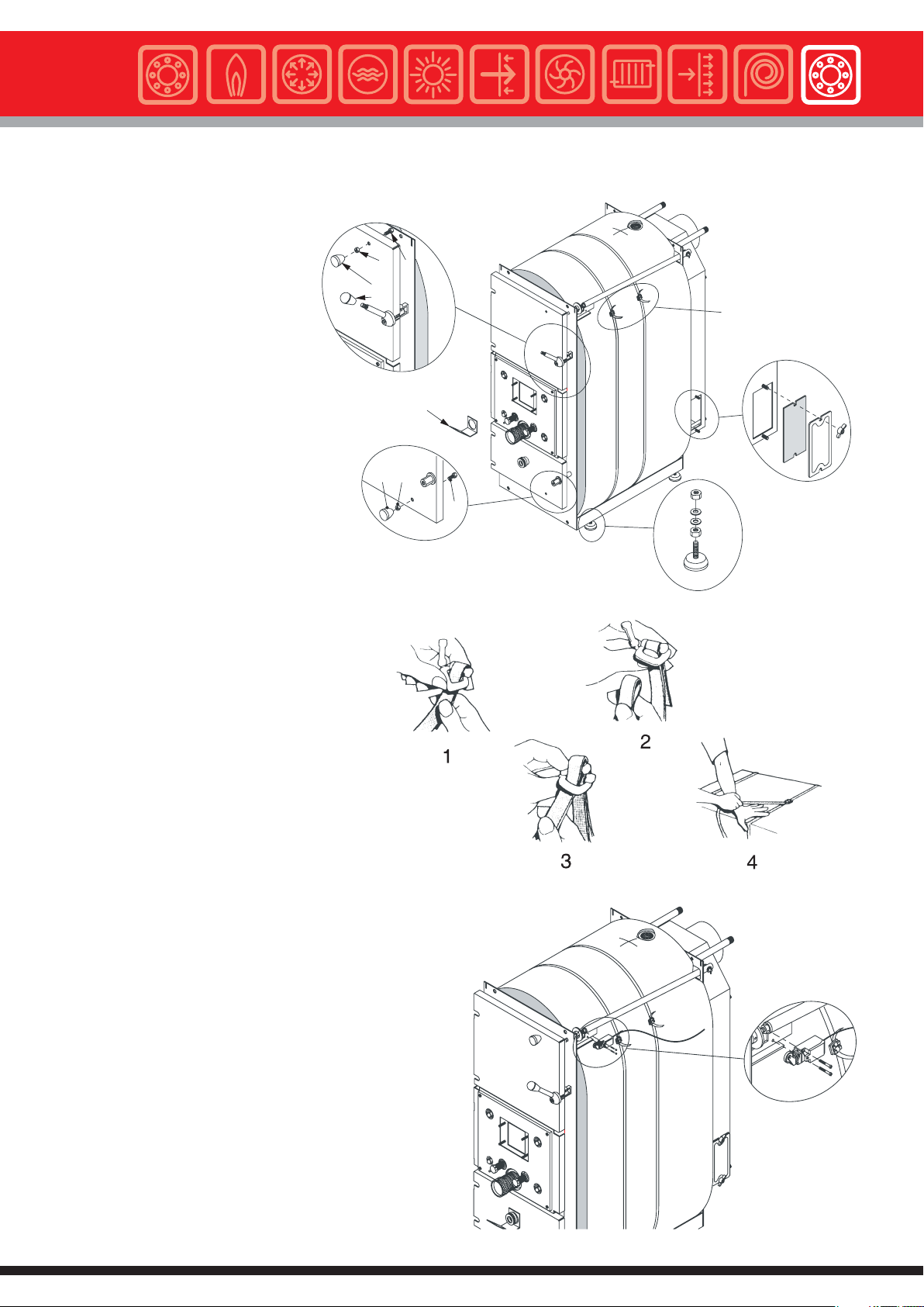
3.9 - INSTALLATION
INSTRUCTIONS
Instructions for the installer
A
Installation of the insulation and
casing
A) Fit the ball grip pos. 4 onto the upper
door closing handle.
B) Fit the screw and nut on the upper
and lower door and screw down the ball
grip (pos. 1, 2, 3).
C) Fit the 4 supporting feet on the lower
L profiles of the boiler body.
D) Fitthe cleaning doors onto the smoke
chamber.
E) Fit the flame sightmirror (pos.5) onto
the lower door’s sight glass.
F) Fit the thermal discharge valve’s bulb
holder (pos. 2, fig. 18).
G) Fit the body insulation and make a
suitable hole near the flow connection
pipe.
H) After fitting the fibre glass insulation
onto the boiler body, pass the plastic
strap provided around it, and insert an
end part in the slot as shown in detail 1
(fig. 12).
Make appropriate cuts in
correspondence of the thermostatic
valves.
2
1
3
4
FIG. 12
D
5
B
2
3
1
C
fig. 11
I) Keeping the end of the plastic strap
already inserted steady, proceed with
the other end by bending, towards the
inside, the plastic pin as shown in detail
2.
L) Pull the ends of the strap (as shown
in details 3 & 4) till it adheres completely
to the glass wool covering the boiler
body.
Please do not pull the strap too much,
as too much compression of the rock
wool insulation will cause an
uniformed insulation
If the boiler needs to be serviced it is possible to remove the
plastic strap by removing the blocking devices.
Fit the microswitch onto its support and adjust the pushing
washer axially in order to allow the microswitch to be regularly
controlled when the upper loading door is closed.
Check that the by-pass disk is perfectly closed when the door
is closed and the boiler in operation.
It is possible to verify this by simulating the closing of the upper
door and observing, from the inside of the fire box, if there are
any spaces.
If necessary, adjust the length of the by-pass shaft, acting on
the front threaded shaft.
fig. 12
fig. 13
17

Gasogen
Instructions for the installer
- Hook the L.H. side casing panel (pos. 1) to the boiler body.
- Hook the R.H. side casing panel (pos. 2) to the boiler body.
- Before fitting the upper panel (pos.3) to the side panel (pos.1
& 2), install the control panel (pos. 4).
- Fit the rear profile supporting the cable clamps (pos. 7).on
the upper panel
- Open the control panel by unscrewing the two side screws.
Lift the control panel’s cover, making it rotate frontwards.
Fit all the thermostat capillaries inside, unrolling them carefully,
the fan(s) connecting cable(s) (outlet), the microswitch cable
door opening control (inlet), and the incoming supply cable
through the two rectangular slots on the base of the control
panel.
- Position the upper casing panel onto the boiler by directing
the capillaries towards the boiler rear.
- Stick the boiler DATA PLATE onto the R.H. side casing panel
after having cleaned the interested area.
Remove the adhesive from the DATA PLATE and stick it on the
boiler making it adhere perfectly.
1
3
4
5
6
2
7
Ref. fig.15 (Models GASOGEN G3 25 2S,GASOGEN G3 40
2S,GASOGENG3502S)
- Fit the air manifold (pos. 1) on to the intermediate door.
- Fit the gasket (pos. 4) and the plate (pos. 5) to the manifold.
- Fit the fan (pos. 7) to the plate.
- Make sure the air non-return plate is not blocked, by moving
the air manifold’s external lever manually.
The primary and secondary air draught adjustmentis described
on page 57.
- Wire the electrical connections (see general wiring
diagram on page 44 and practical wiring
diagrams on
8
9
page 21 & 22).
On the optional control panel (code 23557)
DUPLO IT version, the wiring of the electrical
connections must be carried out as indicated
in the diagrams in 3.11 & 3.12, on pages 24, 26, 29, 31, 33,
36 and 39.
Ref. fig. 16 (Mod. GASOGEN G3 65 2S, GASOGEN G3 80
2S)
- Fit the air manifolds on to the intermediate door.
- Fit the gaskets and the plates to the manifolds.
- Fit the fans to the plates.
- Make sure the air non-return plates are not blocked,by moving
the air manifold’s external lever manually.
The primary and secondary air adjustment is
described on page 57.
- Wire the electrical connections (see general
wiring diagram on page 44 and practical wiring
diagrams on page 21 & 22).
2
3
1
4
5
6
7
Models: GASOGEN G3 25 2S
Models: GASOGEN G3 65 2S
DETTAGLIO B
DETAIL B
GASOGENG3402S
GASOGENG3502S
GASOGENG3802S
fig. 14
B
fig. 15
B
On the optional control panel (code 23557)
DUPLO IT version, the wiring of the electrical
connections must be carried out as shown in the
diagrams in 3.11 & 3.12, on pages 24, 26, 29, 31,
33, 36 and 39.
18
DETTAGLIO B
DETAIL B
fig. 16

Wire the electrical connections as indicated on the general
wiring diagram on page 44 and practical wiring diagrams on
page 21 & 22).
Insert the bulbs of the thermostats in their relevant bulb holders
as shown in fig. 17 and secure them in place with the fixing
springs.
In the optional control panel (code 23557) DUPLO IT
version, the bulbs of the sensors/thermostats to be placed
in the bulb holders are the following:
- Flow sensor (Tc).
- Boiler thermometer
- Safety thermostat (small bulb holder).
The flue sensor bulb must not be inserted.
For the return sensor’s electrical connection (Tr) and for
the relevant problems connected with it, see 5.5.7 (page
52) “Return sensor installation”.
TERMOSTATO
DI ESERCIZIO (Te)
TERMOMETRO
TERMOSTATO
DI MINIMA (Tsc)
MOLLA DI
FISSAGGIO
MOLLA
DI CONTATTO
Instructions for the installer
TERMOSTATO
DI MASSIMA (Tmax)
MOLLA DI
FISSAGGIO
TERMOSTATO
DI SICUREZZA (Ts)
Fit the heat discharge valve (pos. 1) on the safety coil inlet and
insert its sensor in the relevant bulb holder (pos. 2).
It is advisable to redirect the heat safety valve discharge to the
sewage.
The heat discharge valve can be fitted , indifferently, at the
inlet or outlet of the safety coil, provided the valve sensor is
inserted in it relevant bulb holder.
See also chapter 3.7.
fig. 17
1
ALIMENTAZIONE
2
SCARICO
fig. 18
TERMOSTATO DI ESERCIZIO (Te) = WORKING THERMOSTAT
TERMOMETRO = THERMOMETER
TERMOSTATO DI MINIMA (Tsc) = MINIMUM THERMOSTAT
MOLLA DI FISSAGGIO = FIXING CLIP
MOLLA DI CONTATTO = CONTACT SPRING
TERMOSTATO DI MASSIMA (Tmax) = HIGH LIMIT THERMOSTAT
MOLLA DI FISSAGGIO = FIXING CLIP
TERMOSTATO DI SICUREZZA (Ts) = SAFETY THERMOSTAT
19

Gasogen
Instructions for the installer
To ensure correct operation of the GASOGEN G3 2S boilers it
is necessary to fit a recirculation pump in order to avoid low
temperature water returns that could jeopardize the boiler’s
life span.
Automatic Heating, to favour her clients, has developed a water
recirculation kit that optimizes the water recirculation within
the boiler.
This kit is supplied separately as an option and is available, on
request, by indicating the appropriate part number .
The pump’s electric connection must be carried out according
to the general wiring diagram shown on page 44 and the
practical wiring diagrams shown on page 21 & 22.
On the optional control panel (code 23557) DUPLO IT
version, the wiring of the electrical connections must be
carried out as shown in the diagrams in 3.11 & 3.12, on
pages 24, 26, 29, 31, 33, 36 and 39.
14
15
1
2
13
12
11
10
9
8
7
6
RECIRCULATION KIT FOR OPERATION WITH HOTWATER
STORAGE TANK (see 3.12 on page 27)
NOTE: For correct control of the storage tank, in addition
to fitting the recirculation kit, foreseen for this purpose,
the optional control panel code 23577 must be fitted.
To ensure correct operation of the GASOGEN G3 2S boilers,
when a storage tank is used, it is indispensable to install
the return sensor (Tr), as shown in the diagrams in figs. 29,
31, 33, 35 and 37.
Automatic Heating has developed a RECIRCULATION KIT FOR
OPERATION WITH A STORAGE TANK.
This kit is supplied separately as an option and can be ordered
by indicating the code of your own boiler.
The return sensor (Tr) has to be inserted in the bulb holder
pos. 26, placed in the boiler C.H. return connection.
Please refer to the control panel’s instruction manual, in 5.5.7
“Return flow sensor installation” for the return sensor’s (Tr)
electrical connection and for any problems connected with it.
Note: The “MAXP” function (heat discharge pump) will be
carried out by the “MKP” pump (central heating pump) (see
5.3 “Loads and sensors connection diagram”); then connect
the jumper 30-38.
On the optional control panel (code 23557)
DUPLO IT version, the wiring of the electrical
connections must be carried out as shown in the
diagrams in 3.11 & 3.12, on pages 24, 26,
2
29, 31, 33, 36 and 39.
3
4
5
18
19
20
26
27
23
22
1
4
3
5
6
7
25
24
21
10
15
28
fig. 19
17
16
15
14
13
12
11
9
8
fig. 20
20

Instructions for the installer
3.10 - WATER AND ELECTRICAL CONNECTION DIAGRAMS WITH STANDARD CONTROL
PANEL, WITHOUT HOT WATER STORAGE TANK
Foreword!
The diagrams shown here below may be customized.
For particular requirements, please contact our After Sales Service.
Domestic hot water production for a central heating system
with boiler temperature control
via manual mixing valve.
The GASOGEN G3 2S boiler’s standard control panel
automatically switches off the fan and the recirculation pump
in case the boiler temperature, (once 30 minutes have passed
from closing the upper loading door for firing the boiler), does
not reach 65°C (minimum temperature).
The control panel (and the cycle) can only be reset by opening
the loading door for a new restart, or by switching OFF and ON
of the switch in pos. 11.
VE
Pi
VM
IR
The same control panel operation logic will switch OFF the fan
and the recirculation pump when all the wood has finished.
The C.H. system pump will operate only after the minimum
boiler temperature of 65°C has been reached.
When the boiler temperature falls below 65°C, the C.H. pump
will shut down.
Key:
Pr = recirculation pump (if not installed the guarantee is void)
VM = zone mixing valve (if not controlled correctly the guarantee is void)
Pi = central heating system pump
VE = open water tank
IR = heating circuit
TKS = microswitch controlling the opening of the loading door
TA = room thermostat
L1L1L1L1L1L1L1L1L1L1L1L1L1L
NNNN N
123456
4
5
6
-
-
M
L1 N
ALIMENTAZIONE
230V ~ 50Hz
VENTILATORE
M
VENTILATORE
Alimentazione: Mains supply 230V – 50Hz
Ventilatore:Fan
789
6
5
4
7
-
-
8
9
Pr
CALDAIA A LEGNA
WOOD FIRED BOILER
marrone
12 13
10 11
14 15 16 171819 20
13
9
8
7
VE
14
10
marrone
C
13/21
22
14
nero
TKS
19
15
blu
20
16
19
1617171818----
Pi
1
21 22 23 24
20
TA
IR
fig. 21
1011111212----
Pr
VM
fig. 22
21

Gasogen
Instructions for the installer
Domestic Hot Water (DHW) for central heating installation with boiler temperature control via a manual mixing valve.
DHW production via a coiled hot water storage tank or plate heat exchanger with independent installation system and
dedicated loading pump
The GASOGEN G3 2S boiler’s standard
control panel automatically switches off
the fan and the recirculation pump in
case the boiler temperature, (once 30
minutes have passed from closing the
upper loading door for firing the boiler),
does not reach 65°C ( minimum
temperature).
The control panel (and the cycle) can
only bereset by opening theloading door
for a new restart, or by switching OFF
and ON of the switch in pos. 11.
The same control panel operation logic
will switch OFF the fan and the
recirculation pump when the wood is
finished.
The C.H. system pump will operate only
after the minimum boiler temperature of
65°C has been reached.
When the boiler temperature falls below
65°C, the C.H. pump will shut down.
CALDAIA A LEGNA
WOOD FIRED BOILER
IR
VE
Pr
Pi
VM
Pc
PRODUTTORE ACQUA
CALDA SANITARIA
DOMESTIC HOT WATER
fig. 23
STORAGE TANK
Key:
Pr = recirculation pump (if not installed the guarantee is void)
VM =zone mixing valve (if not controlled correctly the guarantee
is void)
Pi = central heating pump
VE = open water tank
IR = heating circuit
TKS = microswitch controlling the opening of the loading door
TA = room thermostat
L1L1L1L1L1L1L1L1L1L1L1L1L1L
NNNN N
123456
6
5
4
4
5
6
-
-
M
L1 N
ALIMENTAZIONE
230V ~ 50Hz
VENTILATORE
VENTILATORE
7
-
-
8
9
M
Alimentazione: Mains supply 230V – 50Hz
Ventilatore:Fan
789
9
8
7
10 11
12 13
12
13
10
marrone
13/21
22
14
nero
TKS
VE
101111
---
Pr
marrone
14 15 16 171819 20
16
14
17
15
C
blu
17
Pi
12
21 22 23 24
VM
1
IR
TA
2
16
C
1
TB (45÷60°C)
Pc
17
fig. 24
22

Instructions for the installer
3.11 - WATER AND ELECTRICAL CONNECTION DIAGRAMS WITH OPTIONAL CONTROL
PANEL BOARD, WITHOUT HOT WATER STORAGE TANK
Foreword!
The diagrams shown here below may be customized.
For particular requirements, please contact our After Sales Service.
Central heating installation with temperature controlled via a motorized mixing valve.
DHW is produced via a coiled hot water storage tank or plate heat exchanger with an independent installation system
and dedicated loading pump.
The two boilers are hydraulically connected in series, with the wood fired boiler system flow connected to the oil/gas
fired boiler’s system return.
There is no need to install a diverting valve, or DHW storage tank loading pump; the DHW tank can be incorporated in
the oil/gas fired boiler.
In the summer, DHW production can be supplied only by the oil/gas fired boiler.
The heating circuit water flows through both the boilers and, in this case, the heat losses are very important.
IMPORTANT: During the installation phase make sure the jumpers’ settings in the control panel are as indicated in
chapter 5.2.
The GASOGEN G3 2S boiler’s standard control panel
automatically switches off the fan and the recirculation pump if
the boiler temperature, (once 30 minutes have passed from
closing the upper loading door for firing the boiler), does not
reach 65°C (minimum temperature).
In this case, or when the wood finishes, the auxiliary boiler will
start firing automatically, provided the selector 22 of the panel
board is on (0) and the burner switch 23 is in pos. II, 30 minutes
after the wood fired boiler temperature falls below 60°C.
The wood fired boiler’s door must be kept closed.
The wood fired boiler, in this case, will be excluded and it will
be possible to restart it after opening the door in order to load
new wood.
If the burner switch 23 is always kept on pos. 0), the back-up
boiler’s burner will be always excluded.
Obviously, to permit operation of the back-up boiler, the control
panel must be in the ON position.
The GASOGEN G3 2S boiler’s control panel (and operation
cycle) can be reset only after the upper door is reopened for a
new restart, or by turning the mains switch 11. OFF and then
ON.
The logic operation of the GASOGEN G3 2S boiler’s control
panel, will switch off the fan and the recirculation pump once
the wood finishes.
The central heating system pump will operate only after the
boiler exceeds the minimum temperature of 65°C.
When the boiler temperature falls below 65°C, the central
heating pump will shut down.
The D.H.W. storage pump will operate in priority compared to
the central heating pump.
The flow sensor (Tc) must be always placed in the boiler’s
bulb holder (see fig. 17).
D.H.W. production will be given priority via the storage tank
loading pump (PR), controlled by a changeover thermostat.
The eventual D.H.W. recirculation pump must be connected to
the mains independently from the GASOGEN G3 2S boiler’s
control panel.
During the summer season we recommend that DHW is
requested via the back-up boiler, or with the wood fired boiler,
provided the indications given on paragraph 6.11, page 59,
are strictly followed.
CALDAIA A LEGNA
WOOD FIRED BOILER
Tc
KKP
IR
MKP
B
VM
VE
M
AB
A
PR
CALDAIA DI SOCCORSO
GASOLIO/GAS
BACK UP BOILER
PRODUTTORE ACQUA
CALDA SANITARIA
DOMESTIC HOT
WATER STORAGE TANK
fig. 25
23

Gasogen
Instructions for the installer
fig. 26
B4
S3
Alimentazione
pompa principale
N
L1
PANNELLO CALDAIA
A GASOLIO/GAS
24
21
22
14
30
11
12
A2
A1
20
T2
T1
NL1
ALLA PRESA A 7 POLI
DEL BRUCIATORE
not installed the guarantee is void)
TC
TR
1
L
1
TKS
L
N
1
NETZ
L
PE
N
1
MAXP
L
1
L
1
TAMB
L
N
1
KKP
L
1
L
NN
1
GM MKP
L
1
L
1
AGW
L
1
1
BV
L
1
SK
L
NNL
1
RAB
L
BS
PE
TYPE 95.05 - 230V
24
C
1
2
C
TA
1
RELÉ A 2VIE
FINDER
PR
51
50
51
-
50
1
49
48
1
1
1
1
1
1
1
1
1
1
1
1
1
1
1
C
47
TKS
46
1
44 45
43
41 42
40
39
38
37
36
35
33
34 35
--
34
33
32
31
30
30
29
272728282929---
28
27
26
25
28 29
24
24
23
22
21
20
20
19
18
17
16
15
-27
M
M
VENTILATORE 1
VENTILATORE 2
IR
AB
A
B
M
MKP
VM
5051-
Tc
34 35
-33
KKP
VE
24
Key:
KKP = recirculation pump (if not installed the guarantee is void)
Tc = wood fired boiler’s flow temperature sensor
VM = zone mixing valve (if
VE = open water tank
MKP = central heating pump
TKS = microswitch controlling the opening of the loading door
PR = D.H.W. buffer storage tank loading pump
PS = D.H.W. recirculation pump (controlled by the D.H.W. thermostat)
IR = central heating installation
TA = room thermostat

Instructions for the installer
Central heating installation with temperature controlled via a motorized mixing valve.
Domestic hot water with a separate coil type storage tank or plate heat exchanger and dedicated loading pump.
Back-up boiler with buffer function when fire wood is finished or for domestic hot water production during summer.
In summer the D.H.W. production can be supplied only by the back up boiler.
The two boilers are hydraulically connected in parallel and the motorized UV diverting valve, will ‘direct’the GASOGEN
G3 2S boiler in the system circuit or the auxiliary boiler alongside: in this circuit the heating circuit water will not flow
through the boiler not operating, thereby reducing the heat losses.
The D.H.W. storage tank will necessarily have to be installed and connected according to the diagram below.
IMPORTANT: During the installation phase make sure the jumpers’ settings in the control panel are as indicated in 5.2.
The GASOGEN G3 2S boiler’s control panel automatically
switches off the fan and the recirculation pump if the boiler
temperature, (once 30 minutes have passed from closing the
upper loading door for firing the boiler), does not reach 65°C
(minimum temperature).
In this case, or when the fire wood finishes, the back-up boiler
will start firing automatically, provided the selector 22 of the
panel board is on (0) and the burner switch 23 is in pos. II,30
minutes afterthe wood fired boiler temperature falls below 60°C.
The door of the wood fired boiler must be kept closed.
The wood fired boiler, in this case, will be excluded and it will
be possible to restart it after opening the door in order to load
new wood.
If the burner switch 23 is always kept on pos. 0), the auxiliary
boiler’s burner will be always excluded.
Obviously, to permit operation of the back-up boiler, the control
panel must be in the ON position.
The GASOGEN G3 2S boiler’s control panel (and operation
cycle) can be reset only after the upper door is reopened for a
new restart, or by turning the mains switch 11. OFF and then
ON.
The central heating system pump will operate only after the
boiler exceeds the minimum temperature of 65°C.
When the boiler temperature falls below 65°C, the central
heating pump will shut down.
The D.H.W. storage pump will operate in priority compared to
the central heating pump.
The diverting valve (UV), will direct the returns towards the
boiler ready to operate in that moment, thus reducing the heat
losses.
The flow sensor (Tc) must be always placed in the boiler’s
bulb holder (see fig. 17).
D.H.W productionwill have priority via the storage tank’s loading
pump (PR),controlled by a changeover thermostat.The D.H.W.
recirculation pump must be connected to the mains
independently fromthe GASOGEN G32S boiler’s control panel.
During summer we recommend that D.H.W. is requested via
the back-up boiler, or with the wood fired boiler provided the
indications given in 6.11, page 59, are strictly followed.
The operation logic of the GASOGEN G3 2S control panel, will
switch off the fan and the recirculation pump oncethe fire wood
finishes.
VE
MKP
B
VM
M
AB
Tc
KKP
CALDAIA A LEGNA
WOOD FIRED BOILER
A
AB
A
B
M
UV
IR
CALDAIA DI SOCCORSO
GASOLIO/GAS
BACK UP BOILER
PR
PRODUTTORE ACQUA
CALDA SANITARIA
DOMESTIC HOT
WATER STORAGE TANK
fig. 27
25

Gasogen
Instructions for the installer
fig. 28
B4
S3
Alimentazione
pompa principale
N
L1
PANNELLO CALDAIA
A GASOLIO/GAS
4
7
1
5
RELÉ A 3VIE
24
8
2
6
9
3
A2
A1
20
N
L1
230V~50Hz
ALIMENTAZIONE
30
C
1
2
30
T2
T1
NL1
ALLA PRESA A 7 POLI
DEL BRUCIATORE
not installed the guarantee is void)
TC
TR
1
L
1
TKS
L
N
1
NETZ
L
PE
N
1
MAXP
L
1
L
1
TAMB
L
N
1
KKP
L
1
L
NN
1
GM MKP
L
1
L
1
AGW
L
1
L
1
BV
L
1
SK
L
NN
1
RAB
L
BS
PE
C
TA
1
51
51
-
50
50
1
49
48
1
1
1
1
1
1
1
1
1
1
1
1
1
1
1
C
47
TKS
46
1
44 45
43
41 42
40
39
38
37
36
35
33
34 35
--
34
33
32
31
30
30
29
272728282929---
28
27
26
28 29
25
24
24
23
22
21
20
20
19
18
17
16
15
-27
M
M
VENTILATORE 1
VENTILATORE 2
IR
MKP
AB
A
B
M
VM
50
51
-
Tc
VE
AB
A
B
34 35
-33
UV
M
KKP
PR
26
Key:
KKP = recirculation pump (if not installed the guarantee is void)
Tc = wood fired boiler’s flow temperature sensor
VM = zone mixing valve (if
VE = open water tank
MKP = central heating pump
TKS = microswitch controlling the opening of the loading door
PR = D.H.W. storage tank loading pump
PS = D.H.W. recirculation pump (controlled by the D.H.W. thermostat)
IR = central heating installation
TA = room thermostat

Instructions for the installer
3.12 - WATER CONNECTIONS AND ELECTRICAL DIAGRAMS WITH OPTIONAL CONTROL
PANEL AND ACCUMULATOR
Dimensioning of the accumulator:
The Standard EN 303-5 says that the minimum heat output for automatically fed boilers should not be higher than 30% of the
nominal heat output (Qn); on the contrary, the minimum heat output can be higher than 30% on manually fed boilers.In our case
the Standard foresees the installation of an accumulator with a volume V equal to:
dove:
V=15xQnxT x(Q
min/Qn
-0,3)
V = volume dell'accumulo (litri)
Q
= potenza utile nominale (kW)
n
T = autonomia (h)
Q
= potenza utile minimale (kW)
min
where:
V = accumulator (buffer tank) volume (litres)
Qn = nominal heat output (kW)
T = autonomy (h)
Qmin = minimum heat output (kW)
The boiler’s nominal heat output (Qn) must be equal to the building’s heat losses. Some of the boiler models are equipped with
automatic or manual systems for the reduction of the nominal heat output in case of reduced load: the minimum heat output, in
which the boiler can work, remaining within the emission levels foreseen by the EN 303-5, is exactly the minimum heat output
Qmin.
The storage tank is not necessary when the requested volume is less than 300 litres.
NOTE: to correctly install the buffer tank it is necessary to use the RECIRCULATION KIT FOR OPERATION WITH THE
ACCUMULATOR which has to be positioned as shown in fig. 20.
27

Gasogen
Instructions for the installer
Foreword!
The system designs shown in the diagrams here below may be customized.
For particular requirements, please contact our After Sales Service.
Simplified water connections diagram between the wood fired boiler and the heat storage tank.
IMPORTANT: During the installation phase make sure the jumpers settings in the control panel are as indicated in
chapter 5.2.
The GASOGEN G3 2S boiler’s control panel automatically
switches off the fan and the recirculation pump if the boiler
temperature, (once 30 minutes have passed from closing the
upper loading door for firing the boiler), does not reach 65°C
(minimum temperature).
The GASOGEN G3 2S boiler’s control panel (and operation
cycle) can be reset only after the upper door is reopened for a
new restart, or by turning the mains switch 11. OFF and then
ON.
The operation logic of the GASOGEN G3 2S control panel, will
switch off the fan and the recirculationpump once the fire wood
finishes.
The central heating system pump will operate only after the
boiler exceeds the minimum temperature of 65°C.
When the boiler temperature falls below 65°C, the central
heating pump will shut down.
The thermal inertia of the wood fired boiler will always be
discharged on the central heating circuit.
VE
The flow sensor (Tc) must be always placed in the boiler’s
bulb holder (see fig. 17).
The return sensor must be always fitted (for the positioning
see fig. 20); see installation mode in paragraph 5.5.7.
The jumper 71-72 on the PCB must be removed.
The introduction of an accumulator in the system of (see
dimensioning on page 27), enables you to obtain a high
seasonal efficiency from the GASOGEN G3 2S boiler and a
better management of
the heating system, as well as a longer life span of the boiler,
by reducing the temperature peaks, caused by inconstant
drawing-offs from the heating system itself.
Moreover, the heat accumulator, makes you save a lot on your
gas bill
This type of installation is particularly effective during the “mid
seasons”, since it avoids having to use reduced wood fire loads
and, consequently, fire the GASOGEN G3 2S under its
minimum output,with the possibilityof creating flue condensate,
which would damage, in a short time, the wood fired boiler.
IR
TT (50-55°C)
Tc
RMV
B
AB
A
Tr
KKP
KRF
CALDAIA A LEGNA
WOOD FIRED BOILER
Legend:
Tc = wood fired boiler flow temperature sensor
Tr = wood fired boiler return temperature
KKP = recirculation pump (if not installed the guarantee is void)
RMV = non-condensing thermostatic valve
KRF = RMV thermostatic valve sensor
PMV1= accumulator thermostatic valve (optional)
VM = zone mixing valve (if not installed the guarantee is void)
28
SVA
PMV1
B
AB
A
SCAMBIATORE AD
ACCUMULATOR (BUFFER TANK)
ACCUMULO
MKP = heating system pump
VE = open water tank
IR = heating system circuit
SVA = accumulator thermostatic valve sensor
TKS = microswitch controlling the door opening
TA = room thermostat
TT= accumulator thermostat
VM
MKP
B
M
AB
A
fig. 29

Instructions for the installer
PE BV
1 111 1 11
15 17 19 21 23 27 30
RAB
BS SK
L1L1L
NNL1NN
16 18 20 22 24 28 3129 32
AGW
GM MKP
1
M
L
1
L
1
L
1
1 1
25
26
24
2728282929----
L
27
VENTILATORE 1
27
28 29
--
M
VENTILATORE 2
51
50
Tc
B
AB
KKP
TAMB
KKP
1
31
30
L1L
L
1
N
1
11
33
34
35 38
36 3937 40
34 35
-33
VE
SVA
49
48
AB
PMV1
B
RMV
A
Tr
MAXP
PE
1
L
1
NNL1L
41 42
TT (50-55°C)
24
A
NETZ
L
1
1
43
44 45
1
C
2
TKS
TR
1
11
46
47
48
TKS
C
1
30
TC
1
49
50
51
49
51
-
50
48
TA
C
1
31
MKP
32
B
VM
M
AB
A
IR
KRF
fig. 30
To permit drainage of the accumulator when the firewood is finished, position the switch 23 of the control panel in pos.
II.
Otherwise, the recovery of the heat stored in the accumulator will be prevented.
In case the room thermostat (TA) does not support the MKP pump load, fit a relay that separates the room thermostat
from the load.
29

Gasogen
Instructions for the installer
Simplified water connection layout between the wood fired boiler, with an accumulator, and D.H.W. production storage
tank.
IMPORTANT: During the installation phase make sure the jumpers settings in the control panel are as indicated in
chapter 5.2.
The GASOGEN G3 2S boiler’s control panel automatically
switches off the fan and the recirculation pump if the boiler
temperature, (once 30 minutes have passed from closing the
upper loading door for firing the boiler), does not reach 65°C
(minimum temperature).
The GASOGEN G3 2S boiler’s control panel (and operation
cycle) can be reset only after the upper door is reopened for a
new restart, or by turning the mains switch 11. OFF and then
ON.
The operation logic of the GASOGEN G3 2S control panel, will
switch off the fan and the recirculationpump once the fire wood
finishes.
The central heating system pump will operate only after the
boiler exceeds the minimum temperature of 65°C.
When the boiler temperature falls below 65°C, the central
heating pump will shut down.
The thermal inertia of the wood fired boiler will always be
discharged on the central heating circuit.
The flow sensor (Tc) must be always placed in the boiler’s
bulb holder (see fig. 17).
The return sensor must be always fitted (for the positioning
see fig. 20); see installation mode in paragraph 5.5.7.
The jumper 71-72 on the PCB must be removed.
The introduction of an accumulator in the heating system (see
dimensioning on page 27), enables you to obtain a high
seasonal efficiency from the GASOGEN G3 2S boiler and a
better management of the heating system, as well as a longer
life span of the boiler, by reducing the temperature peaks,
caused by inconstant drawing-offs from the heating system
itself.
Moreover, the accumulator, makes you save a lot on your gas
bill.
This type of installation is particularly effective during the “mid
seasons”, since it avoids having to use reduced wood fire loads
and, consequently, fire the GASOGEN G3 2S under its
minimum output,with the possibilityof creating flue condensate,
which would damage, in a short time, the wood fired boiler.
D.H.W. production will have priority and will be controlled via
the buffer tank’s loading pump(PR), controlled by achangeover
thermostat. The eventual D.H.W. recirculation pump shall
be connected to the mains independently from the GASOGEN
G3 2S control panel.
VE
SVA
Tc
PMV1
B
AB
Tr
A
SCAMBIATORE AD
ACCUMULATOR
(BUFFER TANK)
ACCUMULO
Legend:
KRF
CALDAIA A LEGNA
WOOD FIRED BOILER
AB
KKP
RMV
B
A
Tc = wood fired boiler flow temperature sensor
Tr = wood fired boiler return temperature
KKP = recirculation pump (if not installed the guarantee is void)
RMV = non-condensing thermostatic valve
KRF = RMV thermostatic valve sensor
PMV1= accumulator thermostatic valve (optional)
VM = zone mixing valve (if not installed the guarantee is void)
During the summer season we recommend that D.H.W. is
produced via the back-up boiler, or with the wood fired boiler,
provided the indications given on paragraph 6.11, page 59,
are strictly
TT (50-55°C)
MKP = heating system pump
VE = open water tank
IR = heating system circuit
SVA = accumulator thermostatic valve sensor
TKS = microswitch controlling the door opening
TA = room thermostat
TT= accumulator thermostat
followed.
MKP
B
VM
M
AB
A
IR
PR
PRODUTTORE ACQUA
CALDA SANITARIA
DOMESTIC HOT
WATER STORAGE TANK
fig. 31
30

Instructions for the installer
PE BV
1 111 1 11
15 17 19 21 23 27 30
RAB
BS SK
L1L1L
NNL1NN
16 18 20 22 24 28 3129 32
19
AGW
GM MKP
1
L1L
L
1
L
1
1 1
25
26
2728282929----
M
27
VENTILATORE 1
27
28 29
--
M
VENTILATORE 2
51
50
Tc
RMV
B
AB
34 35
-33
A
KKP
TAMB
KKP
1
30
31
L1L
L
1
N
1
11
33
34
35 38
36 3937 40
VE
SVA
49
48
PMV1
B
AB
A
Tr
MAXP
1
L
1
NNL1L
PE
41 42
NETZ
L
1
43
TT (50-55°C)
1
24
C
2
1
44 45
TKS
11
46
1
30
1
47
TKS
C
TR
48
TC
1
49
50
51
51
49
-
50
48
IR
31
MKP
32
B
VM
M
AB
A
TA
C
1
2
C
1
TB (45÷60°C)
PR
KRF
32
fig. 32
31
To allow the accumulator to discharge when the firewood is finished, position the switch 23 on the control panel in pos.
II.
Otherwise, the recovery of the heat stored in the accumulator will be inhibited.
In case the room thermostat (TA) does not support the MKP pump load, fit a relay that separates the room thermostat
from the load.
31

Gasogen
Instructions for the installer
Simplified water connection layout between the wood fired boiler, accumulator, and the back- up boiler linked together.
IMPORTANT: During the installation phase make sure the jumper’s settings in the control panel are as indicated in
chapter 5.2.
The GASOGEN G3 2S boiler’s control panel automatically
switches off the fan and the recirculation pump if the boiler
temperature, (once 30 minutes have passed from closing the
upper loading door for firing the boiler), does not reach 65°C
(minimum temperature).
The GASOGEN G3 2S boiler’s control panel (and operation
cycle) can be reset only after the upper door is reopened for a
new restart, or by turning the mains switch 11. OFF and then
ON.
The operation logic of the GASOGEN G3 2S control panel, will
switch off the fan and the recirculationpump once the fire wood
finishes.
The central heating system pump will operate only after the
boiler exceeds the minimum temperature of 65°C.
When the boiler temperature falls below 65°C, the central
heating pump will shut down.
The thermal inertia of the wood fired boiler will always be
discharged on the central heating circuit.
The flow sensor (Tc) must be always placed in the boiler’s
bulb holder (see fig. 17).
The return sensor must be always fitted (for the positioning
see fig. 20); see installation mode in paragraph 5.5.7.
The jumper 71-72 on the PCB must be removed.
The introduction of an accumulator in the heating system (see
dimensioning/sizing on page 27), enables you to obtain a high
seasonal efficiency from the GASOGEN G3 2S boiler and a
better management of the heating system, as well as a longer
life span of the boiler, by reducing the temperature peaks,
caused by inconstant drawing-offs from the heating system
itself.
Moreover, the accumulator makes you save a lot on your gas
bill.
This type of installation is particularly effective during the “mid
seasons”, since it avoids having to use reduced wood fire loads
and, consequently, fire the GASOGEN G3 2S under its
minimum output,with the possibilityof creating flue condensate,
which would damage, in a short time, the wood fired boiler.
The diverting valve (UV), will direct the system returns towards
the boiler ready to operate in that moment, thus reducing the
heat losses.
The accumulator’s temperature , superior to 50-55°C, will
prevent the back-up boiler’s burner firing.
VE
SVA
Tc
PMV1
B
AB
Tr
A
SCAMBIATORE AD
ACCUMULATOR
(BUFFER TANK)
Key:
KRF
CALDAIA A LEGNA
WOOD FIRED BOILER
AB
KKP
RMV
B
A
Tc = wood fired boiler flow temperature sensor
Tr = wood fired boiler return temperature
KKP = recirculation pump (if not installed the guarantee is void)
RMV = non-condensing thermostatic valve
KRF = RMV thermostatic valve sensor
PMV1= accumulator thermostatic valve (optional)
VM = zone mixing valve (if not installed the guarantee is void)
TT (50-55°C)
ACCUMULO
MKP
B
VM
M
AB
A
B
UV
M
AB
A
CALDAIA DI SOCCORSO
GASOLIO/GAS
BACK UP OIL/GAS BOILER
MKP = heating system pump
VE = open water tank
IR = heating system circuit
SVA = accumulator thermostatic valve sensor
TKS = microswitch controlling the door opening
TA = room thermostat
TT= accumulator thermostat
IR
fig. 33
32

Instructions for the installer
fig. 34
TC
TR
1
L
1
TKS
L
N
1
NETZ
L
PE
N
1
MAXP
L
1
L
1
TAMB
L
N
1
KKP
L
1
L
NN
1
GM MKP
L
1
L
1
AGW
L
1
L
1
BV
L
1
SK
L
NN
1
RAB
L
BS
PE
B4
S3
UV
T2
T1
NL1
N
L1
230V~50Hz
ALIMENTAZIONE
AB
A
B
M
KRF
Alimentazione
pompa principale
N
L1
PANNELLO CALDAIA
A GASOLIO/GAS
4
7
1
5
8
2
6
9
3
A2
A1
RELÉA3VIE
20
51
51
-
50
50
1
1
1
1
1
1
1
1
1
1
1
1
1
1
1
1
48
49
-
49
48
C
47
TKS
46
1
44 45
43
41 42
40
39
38
37
36
35
34
33
32
31
31
30
30
29
272728282929---
28
27
26
28 29
25
24
24
23
22
21
20
20
19
18
17
16
15
-27
M
M
VENTILATORE 1
VENTILATORE 2
TA
C
1
30
2
1
C
24
TT (50-55°C)
VE
IR
AB
MKP
A
B
31
SVA
5051-
M
VM
32
A
PMV1
B
AB
49
-
48
Tc
RMV
Tr
A
B
AB
KKP
33
34 35
--
To allow the accumulator to discharge when the firewood is finished, position the switch 23 on the control panel in pos. II.
ad.
In case the room thermostat (TA) does not support the MKP pump load, fit a relay that separates the room thermostat from the lo
Otherwise, the recovery of the heat stored in the accumulator will be prevented.
33

Gasogen
Instructions for the installer
Simplified water connection layout between the wood fired boiler, accumulator and DHW production, and the back-up
boiler linked together (see figs. 35 and 36)
IMPORTANT: During the installation phase make sure the jumpers settings in the control panel are as indicated in
chapter 5.2.
The GASOGEN G3 2S boiler’s control panel automatically
switches off the fan and the recirculation pump if the boiler
temperature, (once 30 minutes have passed from closing the
upper loading door for firing the boiler), does not reach 65°C
(minimum temperature).
The GASOGEN G3 2S boiler’s control panel (and operation
cycle) can be reset only after the upper door is reopened for a
new restart, or by turning the mains switch 11. OFF and then
ON.
The operation logic of the GASOGEN G3 2S control panel, will
switch off the fan and the recirculationpump once the fire wood
finishes.
The central heating system pump will operate only after the
boiler exceeds the minimum temperature of 65°C.
When the boiler temperature falls below 65°C, the central
heating pump will shut down.
The thermal inertia of the wood fired boiler will always be
discharged on the central heating circuit.
The flow sensor (Tc) must be always placed in the boiler’s
bulb holder (see fig. 17).
The return sensor must be always fitted (for the positioning
see fig. 20); see installation mode in paragraph 5.5.7.
The jumper 71-72 on the PCB must be removed.
This type of installation is particularly effective during the “mid
seasons”, since it avoids having to use reduced wood fire loads
and, consequently, fire the GASOGEN G3 2S under its
minimum output,with the possibilityof creating flue condensate,
which would damage, in a short time, the wood fired boiler.
The diverting valve (UV), will direct the system returns towards
the boiler ready to operate in that moment, thus reducing the
heat losses.
The temperature of the accumulator, superior to 50-55°C, will
prevent the back-up boiler’s burner firing.
La produzione di a.c.s.sarà gestita in priorità tramite la pompa
di carico bollitore (PR) comandata da un termostato in scambio, la pompa di ricircolo dell’impianto sanitario dovrà essere
collegata alla rete elettrica indipendentemente dal pannello
strumenti della GASOGEN G3 2S.
Durante il periodo estivo si consiglia di produrre l’a.c.s.con la
caldaia di soccorso, oppure con la caldaia a legna, seguendo
scrupolosamente le indicazioni al cap. 6.11 a pag. 59.
D.H.W. production will have priority and be controlled via the
tank’s loading pump (PR), controlled by a changeover
thermostat. The eventual D.H.W. recirculation pump shall
be connected to the mains independently from the GASOGEN
G3 2S control panel.
The introductionof an accumulator in the system of (see sizing
on page 27), enables you to obtain a high seasonal efficiency
from the GASOGEN G3 2S boiler and a better management of
the heating system, as well as a longer life span of the boiler,
by reducing the temperature peaks, caused by inconstant
drawing-offs from the heating system itself.
Moreover, the accumulator makes you save a lot on your gas
bill.
During the summer season we recommend that D.H.W. is
produced with the back-up boiler, or with the wood fired boiler,
provided the indications given on paragraph 6.11, page 59,
are strictly
followed.
34

Instructions for the installer
fig. 35
IR
CALDA SANITARIA
MKP
PRODUTTORE ACQUA
DHW STORAGE
PR
AB
A
B
M
VM
AB
B
A
M
UV
TA NK
red boiler’s control
TT (50-55°C)
VE
GASOLIO/GAS
BACK UP OIL/
ACCUMULO
ACCUMULATOR
(BUFFER TANK)
GAS BOILER
CALDAIA DI SOCCORSO
SCAMBIATORE AD
A
PMV1
RMV
B
AB
Tr
A
B
AB
KKP
SVA
Tc
not installed the guarantee is void)
KRF
CALDAIA A LEGNA
WOOD FIRED
BOILER
Legend:
Tc = wood fired boiler flow temperature sensor
KRF = RMV thermostatic valve sensor
RMV = non-condensing thermostatic valve
KKP = recirculation pump (if not installed the guarantee is void)
Tr = wood fired boiler return temperature
panel.
UV = wood fired/oil-gas boiler’s diverting valve (it directs the tank’s return to the back up boiler on request of the wood fi
PMV1= accumulator thermostatic valve (optional)
VM = zone mixing valve (if
VE = open water tank
MKP = heating system pump
SVA = accumulator thermostatic valve sensor
IR = heating system circuit
TKS = microswitch controlling the door opening
PR = D.H.W. storage tank’s loading pump
PS = D.H.W. recirculation pump (controlled by the D.H.W. thermostat)
TT= accumulator thermostat
TA = room thermostat
35

Gasogen
Instructions for the installer
4
7
1
5
8
2
6
9
3
A2
A1
RELÉ A 3VIE
20
IR
PANNELLO CALDAIA
A GASOLIO/GAS
Alimentazione
pompa principale
N
L1
TA
C
1
MKP
31
fig. 36
B4
S3
T2
T1
NL1
ALLA PRESA A 7 POLI
DEL BRUCIATORE
TB (45÷60°C)
C
1
2
32
PR
31
N
AB
B
A
M
VM
32
AB
A
B
M
UV
L1
ALIMENTAZIONE
230V~50Hz
ad.
36
TC
TR
1
L
1
TKS
L
N
1
NETZ
L
PE
N
1
MAXP
L
1
L
1
TAMB
L
N
1
KKP
L
1
L
NN
1
GM MKP
L
1
L
1
AGW
L
1
1
BV
L
1
SK
L
NNL
1
RAB
L
BS
PE
51
51
-
50
50
1
1
1
1
1
1
1
1
1
1
1
1
1
1
1
1
48
49
-
49
48
C
47
TKS
46
1
44 45
43
41 42
40
39
38
37
36
35
33
34 35
--
34
33
32
31
31
30
30
29
272728282929---
28
27
26
28 29
25
24
24
23
22
21
20
20
19
18
17
16
15
-27
M
M
VENTILATORE 1
VENTILATORE 2
30
TT (50-55°C)
2
1
C
24
A
PMV1
VE
SVA
5051-
Tc
B
AB
4849-
RMV
Tr
A
B
AB
KKP
34 35
--
33
A PRINCIPALE = MAIN PUMP SUPPLY TO THE BURNER 7 PIN PLUG
MAINS SUPPLY
To allow the accumulator to discharge when the firewood is finished, position the switch 23 on the control panel in pos. II.
In case the room thermostat (TA) does not support the MKP pump load, fit a relay that separates the room thermostat from the lo
Otherwise, the recovery of the heat stored in the accumulator will be inhibited.
KRF
ALIMENTAZIONE:
PANN. CALDAIA = BACK UP BOILER’S CONTROL PANNEL
ALIMENTAZ. POMP

Instructions for the installer
Simplified water connection layout between the wood fired boiler, accumulator, D.H.W. production and the back- up
boiler linked together, in combination with a solar energy system for loading the D.H.W. storage tank and an eventual
integration of the accumulator’s temperature (see fig. 37 & 38).
IMPORTANT: During the installation phase make sure the jumpers settings in the control panel are as indicated in
chapter 5.2.
The GASOGEN G3 2S boiler’s control panel automatically
switches off the fan and the recirculation pump if the boiler
temperature, (once 30 minutes have passed from closing the
upper loading door for firing the boiler), does not reach 65°C
(minimum temperature).
The GASOGEN G3 2S boiler’s control panel (and operation
cycle) can be reset only after the upper door is reopened for a
new restart, or by turning the mains switch 11. OFF and then
ON.
The operation logic of the GASOGEN G3 2S control panel, will
switch off the fan and the recirculation pump oncethe fire wood
finishes.
The central heating system pump will operate only after the
boiler exceeds the minimum temperature of 65°C.
When the boiler temperature falls below 65°C, the central
heating pump will shut down.
The thermal inertia of the wood fired boiler will always be
discharged on the central heating circuit.
The flow sensor (Tc) must be always placed in the boiler’s
bulb holder (see fig. 17).
The return sensor must be always fitted (for the positioning
see fig. 20); see installation mode in paragraph 5.5.7.
The jumper 71-72 on the PCB must be removed.
The introduction of an accumulator in the heating system (see
sizing on page 27), enables you to obtain a high seasonal
efficiency from the GASOGEN G3 2S boiler and a better
management of
the heating system, as well as a longer life span of the boiler,
by reducing the temperature peaks, caused by inconstant
drawing-offs from the heating system itself.
Moreover, the accumulator, makes you save a lot on your gas
bill.
This type of installation is particularly effective during the “mid
seasons”, since it avoids having to usereduced wood fire loads
and, consequently, fire the GASOGEN G3 2S under its
minimum output, with the possibilityof creating flue condensate,
which would damage, in a short time, the wood fired boiler.
The diverting valve (UV), will direct the system returns towards
the boiler ready to operate in that moment, thus reducing the
heat losses.
The accumulator’s temperature, superior to 50-55°C, will
prevent the back-up boiler’s burner firing.
D.H.W. production will have priority and be controlled via the
storage tank loading pump (PR), controlled by a changeover
thermostat. The eventual D.H.W. recirculation pump shall
be connected to the mains independently from the GASOGEN
G3 2S control panel.
During the summer season we recommend that D.H.W. is
produced via the back-up boiler, or with the wood fired boiler,
provided the indications given on paragraph 6.11, page 59,
are strictly
followed.
During the summer you can reduce energy consumption and
save on your fuel bill by using a solar or photovoltaic panel,
which allows you to load the D.H.W.storage tank and, in case
of an over production of energy, to load the accumulator totally
or partially, acting therefore as a buffer.
37

Gasogen
Instructions for the installer
fig. 37
CS
VE1
RS
IR
SP
CALDA SANITARIA
PRODUTTORE ACQUA
PR
red boiler’s control panel.
TT (50-55°C)
VE
AB
MKP
B
A
M
VM
A
PMV1
RMV
B
AB
A
B
AB
SVA
Tc
AB
B
A
M
UV
GASOLIO/GAS
CALDAIA DI SOCCORSO
ACCUMULO
SCAMBIATORE AD
Tr
KKP
not installed the guarantee is void)
38
KRF
CALDAIA A LEGNA
Legend:
Tr = wood fired boiler return temperature
Tc = wood fired boiler flow temperature sensor
KKP = recirculation pump (if not installed the guarantee is void)
RMV = non-condensing thermostatic valve
PMV1= accumulator thermostatic valve (optional)
KRF = RMV thermostatic valve sensor
VE = open water tank
MKP = heating system pump
VE1= closed water tank
IR = heating system circuit
UV = wood fired/oil-gas boiler’s diverting valve (it directs the tank’s return to the back-up boiler on request of the wood fi
VM = zone mixing valve (if
TT= accumulator thermostat
TA = room thermostat
TKS = microswitch controlling the door opening
PR = D.H.W. storage tank’s loading pump
PS = D.H.W. recirculation pump (controlled by the D.H.W. thermostat)
SVA = accumulator thermostatic valve sensor
VD = Diverting valve
SP = Solar collector system pump
RS = Solar collector controller
CS = solar collector

Instructions for the installer
PANNELLO CALDAIA
A GASOLIO/GAS
Alimentazione
pompa principale
N
L1
RELÉ A 3 VIE
20
B4
S3
T2
T1
NL1
ALLAPRESAA7POLI
DEL BRUCIATORE
CS
VE1
SP
fig. 38
RS
N
L1
230V ~ 50 Hz
ALIMENTAZIONE
TB (45÷60°C)
C
1
2
4
7
1
5
8
2
6
9
3
A2
A1
IR
TA
C
1
AB
MKP
A
B
M
31
VM
32
32
PR
31
AB
B
A
M
UV
MAINS SUPPLY
ALIMENTAZIONE:
PANN. CALDAIA = BACK UP BOILER’S CONTROL PANNEL
ALIMENTAZ. POMPA PRINCIPALE = MAIN PUMP SUPPLY
N
L1
ALIMENTAZIONE
TO THE BURNER 7 PIN PLUG
230V~50Hz
TC
TR
1
L
1
TKS
L
N
1
NETZ
L
PE
N
1
MAXP
L
1
L
1
TAM B
L
N
1
KKP
L
1
L
NN
1
GM MKP
L
1
L
1
AGW
L
1
L
1
BV
L
1
SK
L
NN
1
RAB
L
BS
PE
51
51
-
50
50
1
1
1
1
1
1
1
1
1
1
1
1
1
1
1
1
48
49
-
49
48
C
47
TKS
46
1
44 45
43
41 42
40
39
38
37
36
35
33
34 35
--
34
33
32
31
31
30
30
29
272728282929---
28
27
26
28 29
25
24
24
23
22
21
20
20
19
18
17
16
15
-27
M
M
VENTILATORE 1
VENTILATORE 2
0
3
2
1
TT (50-55°C)
C
24
A
PMV1
VE
SVA
B
AB
49
-
48
Tr
A
B
5051-
Tc
RMV
AB
KKP
33
34 35
--
KRF
To allow the accumulator to discharge when the firewood is finished,
position the switch 23 on the control panel in pos. II.
Otherwise, the recovery of the heat stored in the accumulator will
be inhibited.
load, fit a relay that separates the room thermostat from the load.
In case the room thermostat (TA) does not support the MKP pump
39

Gasogen
Instructions for the installer
3.13 - FLUE OUTLET CONNECTION
The flue system must be installed in accordance with the local
regulation and national codes of practice.
The chimney is of fundamental importance for correct boiler
operation: it is therefore necessary that the chimney is
impermeable and properly insulated.
Old or new chimneys, built without respecting the specific
requirements can be recovered by “tubing” the chimney itself.
It will be necessary to introduce a metallic pipe inside the
existing chimney and insulate the space between the metallic
pipe and the chimney.
Chimneys made of prefabricated blocks must have perfectly
sealed joints to avoid that flue condensate leave the walls dirty
due to permeation.
The entrance to the chimney should be at an angle of 45°.
At the base of the chimney a flue inspection opening has to be
made.
It is advisable to insulate the boiler pipe connection to the
chimney in order to reduce the heat losses and noise.
We recommend using only flue outlets
suitable to the type of fuel used.
Damages caused by installation errors and for
non-observance of the instructions given by
the same manufacturer will invalidate all the
supplier’s contractual or extra contractual
responsibilities.
If the boiler has to be replaced ALWAYS replace the flue
outlet system
The flue outlet has to meet the latest regulations in force.
5
6
7
8
4
3
1. Boiler
2. Flue outlet connection
3. Ashes collecting chamber
4. Chimney
5
6
7
8
2
1
fig. 39
5. External flue lining
6. Prefabricated blocks
7. Insulation
8. Flue outlet
40

Instructions for the installer
3.14 - FILLING THE SYSTEM
Warning!
Do not mix the CH system’s water with
unsuitable anti-freeze products (example:
antifreeze
solutions for motor vehicles) or use wrong
concentrations of anti-corrosion solutions
!
This could cause damage to the washers
and could cause noise during normal boiler
operation.
Automatic Heating refuses all liability for
injury to persons, animals or damage to
property deriving from not having respected the above mentioned recommendations.
After completing all the system’s service connections the
circuits may be filled by carefully following out the following
phases:
- open the radiator’s air vents and check that the automatic
air vent in the boiler is working properly.
- gradually open the appropriate filling cock and check that
the automatic air vents fitted onto the system are working
properly.
- close the radiator’s air vents as soon as water begins to
flow out.
- using the pressure gauge check that the pressure reaches
the value of 1 bar (
with a closed expansion vessel - consult local regulations
if this is allowed); for installations equipped with an open
expansion vessel, the reinstatement is carried out
automatically via the same expansion vessel;
- close the system’s filling cock and then bleed off the air
once again through the radiator’s air vents.
- check all the connections for soundness.
- after having fired the boiler for the first time and the system
has reached the correct temperature, arrest the pump and
repeat the air bleeding operations.
- let the system cool down and, if necessary, re-establish
the water pressure to 1 bar(
this isvalid onlyfor installations equipped
this is valid only for installations
equipped with a closed expansion vessel - consult local
regulations if this is allowed) ); for installations equipped
with an open expansion vessel, the reinstatement is carried
out automatically via the same expansion vessel;
fig. 40
NOTE!
In closed circuit heating systems, where allowed, the water
pressure in the heating system - in cold conditions – must not
be lower than one bar; if this value is lower use the filling cock
on the boiler to adjust the pressure.
This operation must be carried out when the system is cold.
Use the pressure gauge, installed near the filling cock, to read
the system’s pressure.
NOTE!
If the boiler has not been fired for a long period the pump could
be jammed.
Before switching on the main switch, it is important to carry out
the following un-jamming operation:
- remove the pump vent plug positioned in the
centre of the pump
- using a screwdriver, rotate the shaft in a
clockwise direction.
Once this operation has been concluded, screw back the pump
vent plug and check that there have been no water leaks.
WARNING!
After removing the pump vent plug some slight
water leakage could occur.Before replacingthe
front panel dry all the wet surfaces.
41

Gasogen
Instructions for the installer
4-5
General Warnings
The appliance’s electrical safety is guaranteed only when the
same appliancehas been correctly earthed in compliance with
the regulations in force. The gas and water feeding pipes and
the CH system pipes cannot be used as ground plates.
Ensure thatthe abovesafety electrical requirements have been
implemented; in case ofdoubt, ask for aprofessionally qualified
engineer to check the appliance’s electrical system.
Automatic Heating refuses responsibility for any damages
arising from failure to earth the boiler correctly.
It is necessary that a qualified technician verifies that the
electrical system is adequate to the appliance’s maximum
absorbed power, indicated on the data plate, checking in
particular that the section of the system’s cables is suitable to
the appliance’s maximum absorbed power.
The use of adaptors, multiple sockets and/or extension cords
For the appliance’s general electrical supply isstrictly forbidden.
The use of any power supplied equipment implies the
observance of he following fundamental rules:
Do not touch the appliance with any wet part of your body
and/or barefooted;
Do not pull the supply cables
Do not expose the boiler to sunlight, rain, etc., unless it is
explicitly foreseen;
Do not permit children or inexpert people to use the appliance
ELECTRICAL CONNECTIONS
Note: It is necessary to fit a double pole switch
on the electrical supply line, havinga3mm
contact separation in both poles, in an easy
accessible position so as to ensure quick andsafe
servicing.
The replacement of the supply cable has to be carried out by a
qualified authorized engineer, using only original spare parts.
The non-observance of the above could compromise the
appliance’s safety.
WARNING!
- Before opening the control panel, position
the switch (11) in the “0”pos.
- Do not connect the control panel to loads
that together absorb more than 4A!
Approvals
The Automatic Heating control panels code 36748 (standard)
and code been CE approved,23557 (electronic, optional) have
according to the EN 60335-1 Standard.
Data plate and factory number
The control panel’s identification data plate is glued on the
base.
Use
This control panel must be used for operation of
a boiler destined to heating water to a
temperature that does not exceed boiling point
when installed.
Connection to mains electrical supply 230V
The general electric connections for the standard control panel
board are shown in page 46 and for the optional control panel
board in the section “ Loads and Sensors connection”
(paragraph 5.3, page 48).
A mains supply of 230 V – 50 Hz is required. The wiring to the
boiler must be in accordance with the current CEI regulations.
DANGER!
The electrical connections must be carried
out only by a qualified engineer.
Before carrying out the connections or any
other operation on the electrical parts,
always switch off and disconnect the
electricity supply and ensure yourself that
it cannot be accidentally turned on.
42

Instructions for the installer
4.1 - STANDARD CONTROL PANEL
The standard control panel (code 36748) operates in a semi-automatic way and is supplied in a cardboard with the following
standard items:
- Microswitch which has to be fitted to the mechanism controlling the bypass rod (TKS) as shown in fig. 13 page 17.
- A 3 pole cable for the fan’s electrical connection (2 fans for the models G3-65 and G3-80)
The connection of the thermostat bulbs to the bulb holders must be carried out as shown in fig. 17, on page 19.
The connection of the loads to the control panel (C.H. pump, recirculation pump, fan, etc.) must be carried out according
to the general wiring diagram in fig. 42 and/or according to the practical wiring diagrams on page 21 and 22.
For installation of the optional control panel (code 23557), on the boiler, with or without the possible accumulator,
recommended by the EN 303-5, refer to paragraph 3.11 on page 23 and/or 3.12, on page 27.
Functional description
Once the main switch pos. 11 and the pump switch pos. 13 are in the ON position, it is possible to light the boiler.
Once the boiler has been fired, close the loading door; in this way the TKS microswitch, operated directly by the rod closing t he
smokes bypass to the chimney, will reset the temporized relay that “will begin to count.”
The factory adjusted time of the temporized relay is of 30 minutes, which can be extended to an additional 30 minutes.
The Tsc thermostat (minimum thermostat) is not satisfied at boiler start-up, because adjusted at 65°C, actually prevents the
C.H. pump running, until this temperature is reached.
If the boiler does not reach the 65°C in the set time, the temporized relay stops the fan.
This can be due to the boiler not firing or due to an insufficient load of the firewood.
To avoid this inconvenience it is possible to increase the temporized relay’s intervention time (this operation has to be done only
by trained personnel) or more firewood has to be loaded.
If the boiler fires in a regular manner, when the boiler reaches 65°C the C.H. pump is activated.
The working thermostat, pos. 32, acting on the fan(s) operation mode, will make the boiler fire in an “automatic” way.
The same thermostat will stop the fan when the preset working temperature has been reached.
In case of boiler overheating (temperature higher than 90°C), and in case of the delayed intervention of the heat relief valve
(remember that in solid fuel boilers, due to high thermal inertia, the installation of this valve is compulsory), the maximum
thermostat Tmax , bypassing the microswitch TKS, the C.H. pump’s thermostatic control Tsc and the pump switch Ipi, will
automatically allow the boiler thermal inertia to discharge into the central heating circuit. This situation could cause an undesired
heating of the radiators, even if the ambient temperature does not request it.
On the fan’s electrical supply there is a safety thermostat Ts that will switch OFF the fan in case
A temperature of 100°C is reached (safety limit temperature).
It is possible to reset this thermostat by unscrewing the cap in pos. 31 and pressing the button underneath.
A room thermostat can be connected on the terminals 19 and 20 after having removed the jumper that links them.
The recirculation pump Pr has to be connected to the terminals 10 and 11.
43

Gasogen
Instructions for the installer
11 Mains switch
12 Fan switch
13 C.H.pump switch
31 Safety overheat thermostat
32 Working thermostat
41 Main fuse (4A)
42 Boiler thermometre
fig. 41
LEGEND WIRING DIAGRAM
Ph Phase (230V ~ 50Hz)
N Neutral
F1 General fuse (max 4A)
IG Mains switch with warning light
Ipi C .H.pump switch
Iv Fan switch
LL Power ON lamp
Pi C.H.system pump
Pr Recirculation pump
44
fig. 42
Rt Temporized relay
R1 Relay
Te Working thermostat (75°C÷85°C)
TKS By-pass shaft microswitch
Tmax Limit thermostat (90°C
Ts Safety overheat thermostat (100°C)
Tsc Minimum thermostat for wood fired boiler (65°C)
V Fan (s)
34
... reference to front view facia panel

Instructions for the installer
5.1 - OPTIONAL CONTROL PANEL
The optional control panel (code 23557) is supplied in a cardboard box with the following standard components:
- Microswitch to be fitted integral with the opening mechanism of the loading door (TKS) (see page 17).
- Flow temperature sensor (Tc): to be fitted on the boiler’s flow connection
- Boiler fan supply cable, with 3 pole plug.
The return temperature sensor (Tr): which must be fitted on the return of the central heating system, if this is equipped with a
heat storage tank, hydraulically connected in parallel to the wood fired boiler (see pages 28, 30, 32, 35 and 38), is not supplied.
The connection of the panel to the loads (C.H. pump, recirculation pump, fan,etc.) and to the sensors, has to be carried
out according to the diagram shown in paragraph 5.3, page 48.
For instructions on how to install the control panel on the boiler equipped with the accumulator recommended by the
Standard EN 303-5, refer to paragraph 5.5.7, on page 52.
Functional description:
Control panel for boiler with a
boiler, without part load function, with chimney sweeper switch (pos. 18 - on the facia panel), with built-in control of the he at
storage tank load (see volume dimensioning of the heat storage tank volume according to EN 303-5 on page 27).
When opening the control panel, the wiring is as shown in the diagram in paragraph 5.6.
pushing fan: ON/OFF fan operation, with the possibility of operating with a gas/oil fired back up
11 Mains switch
12 Fan switch
13 C.H. pump switch
18 Test push button (chimney sweeper)
22 Changeover switch (0)=wood (I)=oil/gas
23 Back up boiler burner switch
fig. 43
31 Safety thermostat
32 Boiler temperature range (75°÷85°C)
41Fuse4A
42 Boiler thermometer
— Led indicating acoustic visual alarm
45

Gasogen
Instructions for the installer
Inside the control panel there are the terminals for the following connections (see wiring diagrams on pages 48 and 53):
- Mains 230V - 50 Hz (Hertz)
- Recirculation pump (KKP) (pre-arrangement)
- Heat discharge pump (MAXP) (pre-arrangement)
- Flue thermostat (AGW) (pre-arrangement)
- Potential free contact for the auxiliary boiler’s burner (BV) (pre-arrangement)
- Back up boiler’s burner electrical supply (SK) (pre-arrangement)
- Heating controller’s electrical supply RAB) (pre-arrangement)
- Flue outlet fire-proof thermostat (BS) (pre-arrangement)
- Fan (GM)
- Central heating system pump (MKP) (pre-arrangement)
- Room thermostat (TAMB) (pre-arrangement)
- Loading door microswitch (TKS)
- Flow temperature sensor (Tc): to be fitted on the boiler flow connection
- Return temperature sensor (Tr) (see paragraph 5.5.7)
- Overheating fan protection thermostat
5.2 - FUNCTIONAL WIRING DIAGRAM (Flow-Chart)
IThe control panel code 23557 is controlled by the mother board equipped with a microprocessor (Motorola
MC68HC908JL3).
The panel’s logical control is described in paragraph 5.4.2 and in a Flow-Chart in the next page that shows its main functions.
The denominations of the single functions are the same in both the paragraph 5.4.2 and in the Flow-Chart.
In Step 0 the “IL” is displayed: it represents the jumper’s position, as described on page 47 (pos. 54 - 55).
This jumper controls the fan’s ignition when the loading door is opened.
If the fan works by pushing, as in the case of the GASOGEN G3 2S boiler, make sure that the jumper on the PINS
54-55isOFF(IL=1).
The status of the logical function, which allows the transfer from the wood fired to the oil/gas fired one, is indicated in the FlowChart with “LG” and associated to the switch in pos. 22 on the facia panel:
Position “0” = LG 1
Position “1” = LG 0
In the Steps 4 and 6 “SPARE” is displayed: it represents the Jumper’s position, as described on page 47 (pos. 56 - 57, fig. 45).
This jumper controls the auxiliary boiler’s ignition.
Make sure this jumper is ON.
In the Flow-Chart there is also the table of the constants used in the built-in program of the mother board’s microprocessor which
identify the working thresholds in comparison to the boiler flow temperature “Tc” and the C.H. return temperature “Tr”:
TSC-LO : Lowest threshold of the wood fired boiler’s minimum temperature.
TSC-HI : Highest threshold of the wood fired boiler’s minimum temperature.
TMAX-LO : Lowest threshold of the maximum temperature allowed for the wood and oil/gas fired boiler
TMAX-HI: Highest threshold of the maximum temperature allowed for wood and oil/gas fired boiler
DELTA:Temperature difference between boiler flow and return (only for loading of the heat storage tank combined with the wood
fired boiler).
KP: Hysteresis on the set boiler temperature (Timp)
TMIN-LO : Lowest threshold of the auxiliary boiler’s minimum temperature.
TMIN-HI : Highest threshold of the auxiliary boiler’s minimum temperature.
46

FLOW -Chart
Instructions for the installer
Switch on control panel
Ventilatore = Fan (GM)
Pompa ricircolo = Recirculation pump (KKP)
Pompa impianto = C.H.System pump (MKP)
Contatto pulito bruciatore = Burner tension-free contact (BV)
Pompa scarico termico = Heat discharge pump (MAXP)
Ponticello inserito : Jumper inserted
fig. 44
47
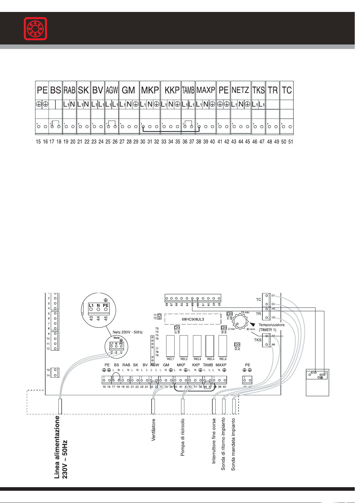
Gasogen
Instructions for the installer
5.3 - LOADS AND SENSORS CONNECTION DIAGRAM
15 = Earthing (PE)
16 = Earthing (PE)
17 = Fire proof thermostat L1 (BS)
18 = Fire proof thermostat N (BS)
19 = Outer compensator supply L1 (Rab)
20 = Outer compensator supply N (Rab)
21 = Electrical supply L1 (SK)
22 = Electrical supply N (SK)
23 = Burner tension-free contact L1 (BV)
24 = Burner tension-free contact L1 (BV)
25 = Flue thermostat L1 (AGW)
26 = Flue thermostat L1 (AGW)
27 = Fan motor L1 (GM)
28 = Fan motor N (GM)
29 = Fan motor (GM)
30 = C.H. pump L1 (MKP)
31 = C.H. Pump N (MKP)
32 = C.H. Pump ( ) (MKP)
33 = Recirculation pump L1 (KKP)
34 = Recirculation pump N (KKP)
35 = Recirculation pump ( ) (KKP)
36 = Room thermostat L1 (TAMB)
37 = Room thermostat L1 (TAMB)
38 = Heat discharge pump L1 (MAXP)
39 = Heat discharge pump N (MAXP)
40 = Heat discharge pump ( ) (MAXP)
41 = Earthing (PE)
42 = Earthing (PE)
43 = Phase L1
44 = Neutral
45 = Earthing (PE)
46 = Limit switch (TKS)
47 = Limit switch (TKS)
48 = C.H. return temperature sensor (Tr)
49 = C.H. return temperature sensor (Tr)
50 = C.H. flow temperature sensor (Tc)
51 = C.H. flow temperature sensor (Tc)
48
Power supply 230 V – 50 Hz
Fan
Recirculation pump
Limit switch
C.H. Return sensor
C.H. Flow sensor
fig.45

Instructions for the installer
5.4 - FUNCTIONAL DESCRIPTION OF OPTIONAL CONTROL PANEL
(see flow-chart on page 47)
5.4.1 - IGNITION (see Step 0, Step 1 page 47)
The main switch (pos. 11), the C.H. pump switch (pos. 13) and the fan switch (pos. 12) are all positioned differently to “0”; t he
switch (pos. 11) is illuminated and the control panel board is ON.
The upper loading door is open: the opening of the door causes the fan to switch OFF (Step 1).
The boiler temperature is below the minimum set temperature of about 65°C.
If the installation is equipped with the accumulator foreseen by the Standard EN 303-5, the return thermostatic valve is closed
(see diagrams on pages 28, 30, 32, 35 and 38).
The opening of the loading door activates a control timer (Timer 1) via the microswitch (TKS): the default value of the Timer 1 is
30 minutes and can be increased during the installation stage of an additional 30 minutes.
If the boiler does notreach the minimum temperature (about 65°C) within the foreseen time Timer 1)), the fan and the recirculation
pump will be switched OFF; in the meantime the back-up boiler’s burner will be activated automatically if the burner switch (pos.
23) is in position “II”
The opening and the closing of the loading door will reset the Timer 1, energizing the
fan and the recirculation pump again.
On the contrary, if the minimum set temperature (higher than 65°C) is reached within the control time (Timer 1), the logical
control will position itself into “normal operation” (Step 3).
5.4.2 - NORMAL BOILER OPERATION (see Step 3, page 47)
The microprocessor’s logical control determines the difference between the boiler temperature (Tc) and the C.H. return temperature
(Tr) and therefore the two following situations can occur:
A - If the difference between the boiler flow temperature (Tc) and return temperature (Tr) is inferior to 6 °C (factory settin g) the
time ofTimer 2 is increased;if this one reaches 10 minutes, then the recirculation pump (KKP) and the fan GM are switched OFF.
B - If the difference between the boiler flow temperature (Tc) and return temperature (Tr) is higher than 6 °C (factory setting) the
Timer 2 is reset to zero and the recirculation pump (KKP) is switched ON.
The above points A and B make up the heat storage tank’s loading strategy, if present (see on page 27).
In general, the opening and closing of the wood loading door, resets the logical control, activating the fan and the recirculat ion
pump again.
In any case the ON and OFF fan function is mainly controlled by the confrontation of the boiler flow temperature (Tc) and the
temperature set by the user via the knob pos. 32.
5.4.3 - NO WOOD (see Step 4, page 47)
The opening of the loading door activates the control timer (Timer 1) via the microswitch (TKS): the default value of the Timer 1
is 30 minutes and can be increased by an additional 30 minutes during the installation stage.
If the boiler does not reach the minimum temperature (about 65°C) within the foreseen time (Timer 1), due to no wood, the fan
and the recirculation pump will be switched OFF; in the mean time the back up boiler’s burner, if the burner switch (pos. 23) is in
position “II”, will be automatically activated. The opening and the closing of the loading door will reset the Timer 1,
switching ON again the fan and the recirculation pump.
On the contrary, if the minimum set temperature (higher than 65°C) is reached within the control time (Timer 1), the logical
control will return to “normal boiler operation” (Step 3).
49

Gasogen
Instructions for the installer
5.4.4 - OIL/GAS BOILER OPERATION (see Step 4, Step 6, page 47)
In installations with a back up oil/gas boiler (hydraulically connected in parallel), the burner is switched ON via the potential free
contact BV, if this has been integrated in the burner’s electrical wiring by the installer; in paragraph 3.11 an auxiliary circ uit
diagram is proposed for controlling: - the C.H. pump, controlled by the back-up boiler’s control panel, - the diverting valve, which
allows the water flow to be diverted from the wood fired boiler to the auxiliary one – the back up boiler’s (oil/gas) burner.
In case there is no wood, the back-up boiler is automatically fired according to the steps seen in the previous paragraph.
On the contrary, if the user needs to operate the back- up boiler without waiting the time foreseen by the Timer 1, he only nee ds
to press the keys 22 and 23 respectively in position “I” and “II”.
5.4.5 - DOMESTIC HOT WATER PRODUCTION
Summer mode for only D.H.W, production is not advisable and could, if not controlled properly, cause the intervention
of the safety overheat thermostat (see paragraph 6.11).
In case the user needs to produce D.H.W, to create these installation systems it is necessary to refer to the principle scheme s
shown on pages 30, 35 and 38.
When designing the system for installing the wood fired boiler and the back up boiler, the engineer has to take into consideration
the increase in output necessary for D.H.W. production; normally, in fact, D.H.W.production has priority over the request for heat
and therefore the sizing of the D.H.W. storage tank volume has to be customized to the user’s needs and at the same time it has
to be calculated when dimensioning the boiler in order to avoid long waiting times for the changeover from D.H.W. mode to CH
mode.
As far as D.H.W. production is concerned, the electrical connection to the control panel is described in the WATER AND
ELECTRICAL CONNECTION DIAGRAMS in paragraphs 3.11 and 3.12.
50

Instructions for the installer
5.5 - SPECIAL FUNCTIONS
5.5.1 - OVERHEATING (see Step 5, on page 47)
The wood fired boiler with manual loading is subject to the thermal inertia phenomena which can cause transitional overheating
periods which have to be contained as much as possible before the intervention of the manual reset safety thermostat.
For this purpose the panel, code 23577, is predisposed for the connection and control of a heat discharge pump via the
terminals MAXP. If the boiler temperature (Tc), in spite of the fan turning off, exceeds the value of 89°C, the heat discharge pump
is activated and remains running until this temperature falls below 86°C.
If the installation is not equipped with a heat discharge pump, the jumper between the MAXP and MKP terminals(see paragraph
5.3 - on page 48) must not be removed;this jumper has in fact the purpose of feeding the C.H. pump even if the room thermostat
(TAMB) is open; this could involve an unrequested heating of the radiators even if the ambient conditions apparently do not
require it.
If the installation is equipped with an accumulator (see paragraph 3.12) the thermal inertia will have to be discharged
through the recirculation pump KKP and therefore it is necessary that the above mentioned jumper is placed between
the MAXP and KKP phase.
there are no closed gate valves between the boiler’s flow and return connections.
5.5.2 - COMBUSTION GAS TEMPERATURE CONTROL (only in case of connection to a single chimney)
For this possibility, check local requirements and rules in force.
In case of flue evacuation in a chimney serving the wood fired boiler and a back-up oil fired boiler (a gas fired boiler needs its
own chimney), it is possible to fit a flue thermostat, in the part of the chimney serving only the wood fired boiler, connected to the
AGW terminals, in order to stop the burner firing in case the flue temperature of the wood fired boiler, is over 100°C.
Obviously in order to allow any thermal discharge via the heating system, it is necessary that
5.5.3 - FAN OVERHEATING PROTECTION SYSTEM
In this range of boilers (GASOGEN G3 2S) this system is not activated.
5.5.4 – TEMPERATURE SENSOR FAILURE ALARM (note for After Sales Service)
If the flow sensor (Tc) malfunctions or is not correctly connected to the relative terminals, the microprocessor’s logical control
activates the acoustic-visual alarm, made up of a LED and a BUZZER, in a continuous mode: if the problem persists, consult the
After Sales Service.
The installation of a heat storage tank (see paragraph 3.12) foresees the connection of the return sensor (Tr) to the dedicated
terminals: to gain access to the previously described alarm service for the Tr sensor, it is necessary that the After Sales Ser vice,
during the installation stage, removes the jumper placed betweenthe pins 71 and 72; if not, the alarm for the Tr sensor malfunction
is inhibited: the manufacturer declines any responsibility.
If the above indicated malfunctions occur, the recirculation pump (KKP), the C.H. pump (MKP) and the heat discharge pump
(MAXP) will be activated, the fan will be turned OFF and the automatic or manual transition to the auxiliary boiler will be
prevented.
The temperature sensor is a NTC resistor. To check that it is in good working condition keep the
following values in consideration:
MEASURED TEMPERATURE
RESISTANCE MEASURED TEMPERATURE RESISTANCE
0 °C 33242 Ohm 50 °C 3548 Ohm
10 °C 19947 Ohm 55 °C 2945 Ohm
15 °C 15659 Ohm 60 °C 2459 Ohm
20 °C 12394 Ohm 65 °C 2063 Ohm
25 °C 9888 Ohm 70 °C 1740 Ohm
30 °C 7947 Ohm 75 °C 1475 Ohm
35 °C 6433 Ohm 80 °C 1256 Ohm
40 °C 5242 Ohm 85 °C 1075 Ohm
45 °C 4300 Ohm 90 °C 923 Ohm
51

Gasogen
Instructions for the installer
5.5.5 - FIRE PROOF THERMOSTAT
A fire proof thermostat can be connected to the control panel in order to switch off the fan, connected to the terminals BS so as
to arrest combustion in the wood fired boiler.
5.5.6 - WAITING TIME (After Sales Service function)
The default waiting time (Timer 1) is equal to 30 minutes; to make commissioning easy at the boiler installation stage, the mot her
board is equipped with a logical function that allows the waiting time to be reduced to 3 minutes: the installer to gain access to
this function has to position the jumper, supplied with the boiler, between the pins 69 - 70.
WARNING: The installer, once the commissioning is finished, must remove the a.m. jumper from the terminals 69 - 70, in order
to restore normal operation: the manufacturer declines any responsibility and/or additional costs connected if normal boiler
operation is not restored.
5.5.7 - RETURN FLOW SENSOR (Tr) INSTALLATION
The installation of the accumulator foresees the connection of the return sensor (Tr) to the dedicated terminals (see paragraph
3.12, page 27): it is necessary that during the installation stage the After Sales Service removes the jumper placed on the
pins 71 and 72.Otherwise, the Tr sensor failure alarm and the control of the KKP pump for loading the accumulator are inhibite d:
the manufacturer declines any responsibility if this occurs.
52

5.6 - WIRING DIAGRAM OPTIONAL CONTROL PANEL
Instructions for the installer
Control panel – rear view
LEGEND :
1÷4 Mains supply 230 V - 50 Hz
5, 6 C.H. pump
7, 8 Fuse 4A
9,10 Fan
11, 12 Safety overheat thermostat
13, 14 Back-up boiler burner
43, 45 Mains supply
58, 59 Changeover switch wood fired / auxiliary boiler
60, 61 Wood fired boiler test push button (Chimney sweeper)
62, 63 Acoustic-visual alarm thermostat (fan overheating)
64, 65 Acoustic-visual LED alarm (fan overheating)
66÷68 Wood fired boiler flow temperature adjustment range (75÷85 °C)
REL 1 Fan (GM)
REL 2 Burner (BV)
REL 3 Recirculation pump (KKP)
REL 4 C.H. system pump (MKP)
REL 5 Heat discharge pump (MAXP)
Mother board
fig. 46
53

Gasogen
Instructions for the installer
6
BOILER START-UP
6.1 - INITIAL LIGHTING
Preliminary checks
The first ignition must be carried out by a
qualified technician. Failure to do so could
cause injury to persons, animals or damage
to property. Automatic Heating shall not be
held liable for any injury and/or damage
Before firing the boiler check that:
- the boiler installation has been carried out in accordance
with the specific Standards andregulations in force relating
to the gas part and to the electrical part;
- the air supply and the discharge of the products of
combustion are carried out inthe correct way in accordance
to the specific Standards and regulations in force;
- the boiler is fitted with all the safety and control devices
prescribed by the regulations in force;
- the electrical supply must be 230 V - 50 Hz;
- the C.H. system has been filled with water;
- any gate valves of the CH system are open;
- the gasfor the back-up boiler corresponds to the onewhich
the boiler has been calibrated for: otherwise convert the
boiler touse the available gas; this operation must be carried
out by a qualified technician in compliance to the regulations
in force;
- the gas supply cock for the back-up boiler, if present, is
open;
- there are no gas leaks;
- the external mains supply switch is on;
- the system’s safety valve on the boiler is not blocked and
that it is connected to the sewage system;
- there are no water leaks;
- all the necessary ventilation conditions and minimum
clearance distances are guaranteed for subsequent
servicing.
.
- Inform the user of the importance of the air vents and of
the flue outlet system, stressing the fact that absolutely
no modification can be made.
- Inform the user about controlling the system water
pressure and how to restore it to the correct value.
- Explain and demonstrate to the user the correct function
and adjustment of the temperature, thermostats and
radiators for the economic use of the system.
- Remind the user that a comprehensive service and the
measurement of the combustion efficiency should be
carried out regularly (as requested by the regulations in
force).
- If the appliance is sold or transferred to another owner or
if the present user moves home and leaves the appliance
installed, ensure yourself that the manual always follows
the appliance so that it can be consulted by the new
owner and/or installer.
LIGHTING AND SHUTTING DOWN PROCEDURES
For lighting and shutting down the boiler refer to the “USER
INSTRUCTIONS MANUAL”
Information to be passed on to the user:
The user must be instructed on the use and operation of the
boiler and the hearing system, in particular:
- Hand the user the : “USERS INSTRUCTION MANUAL”, as
well as all the other literature relative to the appliance, and
placed in the envelope contained in the packaging. The
user must keep this literature for any future reference.
54

6.2 - FIRE WOOD
Instructions for the installer
Wood is formed mainly by cellulose and lignite. It
contains other substances, such as resin
(fir tree - pine), tannin (oak - chestnut) and,
obviously, a large quantity of water.
Good quality woods are oak, ash, beech, maple
and fruit trees, except cherry; medium quality wood
is: chestnut and birch; sufficient quality wood:lime
6.3 - WOOD MOISTURE
The calorific value of the different types of wood
depends on their moisture content, as shown on
the table.Boiler output and autonomy will diminish
as the moisture increases.In the table a reduction
factor is indicated according to the moisture
content of the wood used. The heat output of the
GASOGEN G3 2S boiler is calculated for wood
with a 15% moisture content.
As an example wood which has been dried for 2
years air in a protected area has a 25% moisture
content.
Example:
Moisture content of wood used = 30%
Heat output = nominal heat output x 0,79
tree, poplar and willow. Resinous trees are, normally, medium
quality fuels.
Wood is therefore an extremely heterogeneous fuel, due to
different essences (beech, oak, fruit, resinous), different
moisture content, and due to different shapes and dimensions.
Boiler operation will of course be certainly effected by all these
factors.Especially by the log dimensions, the moisture content
and the way wood is loaded in the boiler.
Correction factors for wood moisture content
%
moisture
15
20
25
30
35
40
45
50
Calorific
value
kcal/kg
3.490
3.250
3.010
2.780
2.540
2.300
2.060
1.820
Correction
factor
1
0,93
0,86
0,79
0,72
0,65
0,59
0,52
6.4 - FIRE WOOD DIMENSIONS
The dimensions, together with the moisture
content, contribute to determine the boiler’s output
Small pieces (with a length, however, conforming
to indications hereby indicated) are more easily
inflammable and therefore have the tendency to
increase theboiler’s output and therefore toreduce
its autonomy. Moreover, they fall with greater
6.5 – INITIAL LIGHTING CHECKS
GENERAL CONTROLS
During the first ignitioncheck that the C.H. system
has been properly filled and properly purged, that
the safety heat exchanger is connected to the
water mains via the heat safety discharge valve
(fig. 10, page 16 and fig. 18 page 19) – that the
chimney hasa sufficient draught, that the electrical
connection has been made correctly (paragraph
4 &5) and that the recirculation and boiler pumps
are not blocked.
Furthermore check that the stainless steel
grate and the fire bars are properly positioned.
THE BY-PASS
The by-pass is a direct passage between the fire
wood storage and the chimney. It is normally
closed by a mobile shutter. The by-pass is
facility, in the lower chamber, reducing the risk of the formation
of “bridges”. The so-called “bridge” is an empty space in the
firebox, where unburnt wood logs remain . In this case the bed
of embers is not fed with continuity and
the refractory burner’s slot is uncovered. In these conditions,
preferential air passages are created with a very small flame
due to an excess of air.
automatically opened or closed via a pushing rod when the
loading door is opened.
In this way the smoke accumulated in the firebox is aspirated
and sent to the chimney directly.
The bypass, in conclusion, allows the smoke to be discharged
at the chimney without escaping from the loading door when
loading the wood or during lighting.
Any way it is essential to open the loading door slowly and, as
well, to rotate the antismoke flap (pos. 4, fig. 2) gradually so
that the smoke is effectively aspirated.
BY-PASS CONTROL
During the installation stage and, in any case, before starting
to use the boiler, check that the by-pass is correctly closed
and the correct position of the microswitch, which controls the
opening of the door. In this way when the door is closed the
fan has to start rotating; when the door starts to
open the fan has to be OFF, otherwise all the smokes comes
out.
55

Gasogen
Instructions for the installer
6.6 - START-UP
IGNITION
Make sure all the controls listed in 6.5 have been
carried out.
For the GASOGEN G3 25 2S, GASOGEN G3 40 2S and
GASOGEN G3 50 2S models:
Screw down completely the primary air’s (P) adjustmentscrew
Screw down completely the secondary air’s (S) adjustment
screws until you “detect” the resistance of the spring pushing
the closing discs.
Now, “unscrew” about 10 turns the primary
Air’s (P) screw and 4 turns the secondary air’s (S) screws.
FortheGASOGENG3652SandGASOGENG3802S
models:
The initial position of the ring nuts (pos. 1, fig. 48) which
control the opening or closing of the primary and secondary
air, has to be about in the middle of the threaded rod.
The primary air (P) is blown through the upper fan, whilst the
secondary air (S) is blown through the lower one.
At this point, “screw” or “unscrew” the ring nuts (pos. 1, fig.
48) onthe threaded rod until you have an optimal airregulation,
by observing the colour of the flame inthe combustion chamber;
keep in mind that by rotating the ring nuts in a clockwise
direction (that is upwards) you will have an increase of the
emission of the air (primary or secondary), vice versa, a
reduction.
C = Ventilation control box
S= Secondary air adjusting screws
P= Primary air adjusting screw
P1 = Primary air passages
S1= Secondary air passages
Models: GASOGEN G3 25 2S
GASOGENG3402S
GASOGENG3502S
P1
C
S
P
S
Models: GASOGEN G3 65 2S
GASOGENG3802S
P
S
1
S1
P1
fig. 47
Open the upper loading door and place above themain stone’s
central slot, some thin and dry pieces of wood, in a crosswise
position.
Prefer easily inflammable wood,avoiding bigpieces and square
shaped pieces.
Open the lower combustion chamber door.
Using sheets of thin paper (newspapers or similar) light the
wood previously placed inside.
Leave the upper door ajar.
Wait several minutes until the fire starts and produces some
embers (about 5 - 10 minutes).
Close the lower door first and then the upper door: at this
moment the fan is automatically switched ON (point 6.1).
After some minutes, if you look through the sight glass, it is
possible to see that the flame
starts reversing downwards, so you can add some other larger
wood pieces.
Important: during boiler operation the bypass must be
always perfectly closed.
The wood has to be of the following length, according to the
boiler model:
a) 50 cm (+ 1 cm, - 4cm) for the GASOGEN G3 25 2S and
GASOGEN G3 40 2S models
b) 70 cm (+ 1 cm, - 4 cm) for the GASOGEN G3 50 2S and
GASOGEN G3 65 2S models
c) 100 cm (+ 1 cm, - 4 cm) for the GASOGEN G3 80 2S model
These dimensions must be absolutely respected.
In order to have a good combustion it is essential that the wood
falls down ina uniformed way.Therefore it is necessary to make
sure that the length of the wood logs introduced, their shape
P= Primary air ventilation control box
S = Secondary air ventilation control box
1 = Ring nut air adjustment
and the way they are loaded does not prevent the wood from
falling down in a regular way.
The wood logs must be placed lengthwise and in a horizontal
direction.
No log must be placed in an oblique or slanted direction.
SUBSEQUENT WOOD LOADINGS
Before carrying out a new loading of wood use up the previous
load as much as possible.
The new load can be made when the bed of embers is about 5
cm thick.
Slowly open the upper loading door and the inner anti smoke
flap.
The wood logs must have the length specified in the previous
paragraph and they must be placed as previously described.
USEFUL SUGGESTIONS and LOADING ERRORS TO BE
AVOIDED
- Logs too long do not fall down properly and can cause
obstructions.
- Logs too short cause irregular air passages, with consequent
reduction in output and efficiency.
- In case the quality of the wood causes “obstructions” it could
become necessary to cut the wood logs in two parts, as shown
in fig. 49, in order that the total length “L” is as indicated in the
previous paragraph.
- Always open the upper door slowlyin order to avoid blowbacks
and smoke formation.
- During normal boiler operation it is absolutely forbidden to
open the lower combustion door.
fig. 48
56

Cut
fig. 49
6.7 - COMBUSTION AIR ADJUSTMENT
Instructions for the installer
PRIMARY AND SECONDARY AIR ADJUSTMENT
The GASOGEN G3 2S boiler is equipped with a
ventilation control box for combustion air (fan pos.
7 fig.2) and with primary (pos. P, fig. 47) and
secondary air adjusters. (pos. S, fig. 47).
TheGASOGENG3652SandGASOGENG380
2S boilers are equipped with two fans (fig. 48)
which incorporates a non-return valve, controlled by external
ring nuts.The upper fan supplies the primary air, the lower fan
the secondary air.
During the first ignition it is necessary to adjust the primary
and secondary air, keeping in mind that the primary air
determines the boiler’s output and therefore the quantity of
wood burnt, whilstthe secondary air completes the combustion.
For correct air adjustment it will be necessary to observe the
flame through the sight glass placed on the lower door. The
flame will have to occupy about two thirds of the combustion
chamber, and will have to quietly lick the lower cradle, without
moving the ash too much and without making any noise.
The flame must be an orange-pink-white colour, not too
transparent and with the centre part veering to light blue.
To bring the flame to optimal conditions, it will therefore be
necessary to regulate theprimary air by screwing orunscrewing
the screw (pos. P); the same operation must be carried out for
the secondary air (pos. S).
For the GASOGEN G3 65 2S and GASOGEN G380 2S boilers
the primary air adjustment is achieved by acting on the upper
fan’s external ring nut; for the secondary air by acting on the
lower fan’s external ring nut.
Example n.1
Thick, wet wood logs = difficult combustion
S - Very closed (try to get the maximumdimension of the flame,
but not a reddish colour).
P - Reasonably open in order to obtain a sufficient gasification.
Example n. 2
Very inflammable wood logs
S - Completely open.
P - Slightly closed to reduce the gasification, but sufficiently
open to evacuate the ash that can close the combustion head.
GENERAL SUGGESTIONS
- Better performances are obtained after two - three days of
operation. The refractory cement, in fact, needs to be baked
and the tar has to cover the upper part of the fire box.
- The flame has to have good dimensions and reasonably
fill-up the combustion chamber.
-Theflame must not be too red (lack of secondary air S).
-Theflame must not be too blue (excess of secondary air S).
-Theflame must not be too noisy (excess of primary air P).
-Theflame must not be too small (lack of primary air P).
-Ifthe ash does not falls down properly - increase the
primary air P.
-Iftoo much ash falls down - reduce the primary air P.
-Ifthe chimney smokes - open the secondary air S
completely.
-Ifthe chimney continues smoking - adjust the secondary
air S to maximum and reduce the primary air. P.
AIR ADJUSTMENT FAULTS
1) If the primary air is excessive a lot of ash and small pieces
of coal will fall through the slot into the combustion chamber.
The flame is too fast, dry, a cold colour and makes a noise.
The boiler is consuming a lot of wood and the door’s refractory
insulation is white.
2) If the primary air is insufficient the flame will be slow,
indecisive, influenced by air currents and by the chimney
draught, very small, incapable of touching the lower cradle,
with low ash production and the door’s refractory insulation
will be of a dark colour.
3) If the secondary air is excessive the flame will be small, a
blueish colour and very transparent.
4) If the secondary air is insufficient the flame will be big, it
will touch the lower cradle, it will completely fill the combustion
chamber and, above all, it will be a red colour and not
transparent
57

Gasogen
Instructions for the installer
6.8 - CHECKS TO CARRY OUT AFTER THE
FIRST START-UP
SOUNDNESS CHECK
During the first start-up check the soundness
of the seals of the flue circuit and the chimney
connection.
If younotice smoke leakages inform the installer
or the After Sale Service. If you notice air
suctions through the door’s seals, close the door handle with
greater strength.
Check the normal operation of the working thermostat Te (32)
at full capacity (paragraph 4.1 and 5.1) until it arrests the fan.
Check there are no water leaks from the water connections.
After the first start-up, with the boiler OFF, open the lower door
and inspect the internal walls and the door insulation which
has tobe of awhite colour, indication of a correct airadjustment.
On the contrary, if the walls are blackened, it means that the
secondary air is not working properly (paragraph 6.7 and 6.9).
6.9 - WARNINGS
HOWTO AVOID CORROSION IN THE FIRE WOOD BOX
The use of wood with a high moisture content
(higher than about 25%) and/or loadings not
proportioned to the system’s heat request
(long OFF periods with the wood storage full)
can cause considerable condensate formation
in the wood storage’s internal wall.
Check, once a week, the internal steel walls of the fire box.
They must be covered by a slight layer of opaque coloured,
dry tar, with bubbles inclined to break and fall off.
On the contrary, if the tar is bright, runny and, if removed with
the fire stoke, some liquid appears, it is necessary to use wood
with a lower moisture content and/or reduce the quantity of the
wood when loading the boiler.
If, in despite of these interventions the tar does not dry, you
must inform the local After Sales Service of this.
The condensate inside the fire box causes the corrosion
of the steel plates.
Corrosion is not covered by the guarantee, because it is
caused by a bad use of the boiler (wet wood, excessive
loadings, etc.).
CORROSION IN THE FLUE CIRCUIT
The flue is rich in water steam, due to combustion and the use
of wood which always retains water.
If the flue comes into contact with relatively cold surfaces (with
a minimum temperature of about 60 - 70 °C), the steam water
condensates and in combination with other combustion
products originates corrosion phenomena of the metallic parts.
Every day check ifthere are signsof smoke condensation (black
liquid on the floor, behind the boiler).In this case you must use
a wood with a lower moisture content; check that the
recirculation pump is working correctly, the flue temperature
at part load, and increase the working temperature.To control
the room temperature it is therefore necessary to install a
mixing valve. The corrosion caused by flue condensation is
not covered by the guarantee, because it is caused by the
wood’s moisture content and the way the boiler is used.
PRECAUTIONS TO BE TAKEN DURING BOILER
OPERATION
After every air adjustment , wait 5 to 10 minutes before making
a new adjustment. Once the best adjustment has been
established, at the end of the day check that the surfaces of
the combustion chamber and the door insulation are of a white
colour.
In the ash deposited in the cradle there must be only a few
unburnt embers. If the primary air is in excess, in the ash there
will be embers and small pieces of coal, the flame will burn
fast, dry, have a cold colour and be noisier, and the output will
be excessive (paragraph 6.7).
If the primary air is insufficient the flame will be slow, small, it
will not touch the lower cradle andwill drag little ash;the output
will be insufficient.
If the flame is a dark orange colour, the secondary air is
insufficient and the surfaces of the combustion chamber will
not be a white colour; if it is small and blue there is too much
secondary air.
Always open the upper loading door and the internal antismoke
flap slowly.
If, in despite of these precautions, some blow back will occur,
it will be necessary to use bigger pieces of wood, with a higher
moisture content, and to check that the boiler does not remain
unused for a long time (reduce the primary air - paragraph 6.7)
and make sure that the possible distortion of the cast iron fire
bars or the modification of the stainless steel grates or that the
presence of extraneous bodies (nails, metallic pieces) has not
obstructed the refractory burner’s slot.
58

6.10 - THERMOSTAT ADJUSTMENT
WOOD FIRED BOILER
The boiler’s adjustment thermostat must be set
to the desired temperature (the adjustment
range,
limited by stoppers that must not be removed,
varies from 75° to 85°C).
To adjust the boiler’s flow temperature to the heating system it
is necessary to foresee the installation of a 3 or 4 way mixing
valve.
If this mixing valve is not installed the guarantee will be
void.
The manual reset safety thermostat, pos. 31, complies to the
regulations in force.
At the start-up stage check if it has to be reset.
To do this unscrew the plastic protecting cap and press the
reset button; then replace the plastic cap.
If the boiler safety’s thermostat has to intervene frequently,
pos. 31, reduce the setting temperature of the working
thermostat (pos. 32 on the control panel).
If this problem is repeated, inform the local After Sales Service.
Instructions for the installer
6.11 - SUMMER OPERATION
Use of the boiler in summer for the production
of onlydomestic hot water is not advised, unless
you follow these rules meticulously:
1) Use very dry wood
2) Do not load the boiler with too much wood,
load the boiler partially, 2 or 3 times per day
according to need.
6.12 - BURNER ADJUSTMENT ON
BACK- UP BOILER
The burner must be serviced exclusively by an
authorized service technician.
Important.
It is absolutely wrong to load the boiler
completely so as to gain very long working
periods (for
example 24 hours). Doing so the boiler (when
the fan is OFF) will produce a lot of acid
condensate
and corrode the fire box.
59

Gasogen
Instructions for the installer
6.13 - FAULT FINDING FOR BOILER WITH
STANDARD CONTROL PANEL
WOOD FIRED BOILER:
Problem:
- The fan does not start
Remedy:
- Adjust the working thermostat (pos. 32) to maximum.
- Reset the safety thermostat (pos. 31).
Problem:
- The fan starts, but after 30 minutes it stops;
by switching OFF and ON the main switch (pos. 11) it re-starts.
Remedy:
- Increase the temporized relay’s intervention time
(this has to be done by the After Sales Service or by
authorized trained personnel after switching OFF the
mains supply).
Problem:
- When opening the loading door there are blowbacks
and flue formation.
Remedy :
- Open the door slowly.
- Usewood with a higher moisture content;make sure the boiler
does not remain unused for long periods (see paragraph 6.9).
- Use thicker wood logs.
- Use up all the wood before loading a new batch
Problem:
- The boiler does not reach the requested temperature. The
flame is too small.
Remedy:
- Check if the by-pass is closed.
- Check the fan
- Check if the doors are properly closed
If you cannot solve the problem, do no attempt
any other interventions and contact an
authorized Automatic Heating After Sales
Service.
Problem:
- The boiler does not reach the requested temperature.
The flame is small and there is too much air.
When thefire box is checked a formation oflog bridges is found.
Remedy:
- Check the length of the wood logs (see paragraph 6.6).
- Check how the wood logs are loaded in the fire box (see
paragraph 6.6).
- Cut the logs in two parts (see paragraph 6.6).
- Use smaller logs (round or square, 5 to 7 cm diam. )
- Mixmedium-large sized logs (15-20cm diam.)with small sized
logs (see previous point).
60

6.14 - FAULT FINDING FOR BOILER WITH
OPTIONAL CONTROL PANEL
WOOD FIRED BOILER:
Instructions for the installer
Problem:
- The fan does not start
Remedy:
- Adjust the working thermostat (pos. 32) to maximum.
- Reset the safety thermostat (pos. 31).
Problem:
- The fan starts, but after 30 minutes it stops;
by switching OFF and ON the main switch (pos. 11) it re-starts.
Remedy:
- Increase the TIMER 1 intervention time
(this operation has to be carried out by the After Sales
Serviceorby
authorized trained personnel after switching OFF the
mains supply).
Problem:
- When opening the loading door there are blowbacks
and flue formation.
Remedy:
- Open the door slowly.
- Usewood with a higher moisture content;make sure the boiler
does not remain unused for long periods (see paragraph 6.9).
- Use thicker logs.
- Use up all the wood before loading a new batch
Problem:
- The acoustic-visual alarm system is activated in a continuous
mode.
Remedy:
- Make sure the flow sensor is properly connected.
- Check that the flow sensor is working correctly.
- Inform the After Sales Service.
If you cannot solve the problem, do no attempt
any other interventions and contact an
authorized Automatic Heating After Sales
Service.
Problem:
- The boiler does not reach the requested temperature.
The flame is small and there is too much air.
When thefire box is checked a formation oflog bridges is found.
Remedy:
- Check the length of the wood logs (see paragraph 6.6).
- Check how the wood logs are loaded in the fire box (see
paragraph 6.6).
- Cut the logs in two parts (see paragraph 6.6).
- Use smaller logs (round or square, 5 to 7 cm diam. )
- Mixmedium-large sized logs (15-20cm diam.)with small sized
logs (see previous point).
Problem:
- The boiler does not reach the requested temperature. The
flame is too small.
Remedy:
- Check if the by-pass is closed.
- Check the fan
- Check if the doors are properly closed
61

Gasogen
Servicing schedule
7
SERVICING & MAINTENANCE
SCHEDULE
To ensure the continued safe and efficient
operation of the boiler it is highly
recommended that it is checked at regular
intervals and serviced when necessary, and
that only original spare parts are used.
Regular attention will prolong the boiler’s life
span.
If the boiler is not checked and serviced
regularly it could cause material and
personal damages.
For this reason Automatic Heating recommends that a servicing
contract should be made with one of our authorized After Sales
Service Assistance Centre.
The boilermust have regular maintenanceand cleaning inorder
to ensure reliable and efficient operation. Regular attention
will prolong the boiler’s life span.
The frequency of servicing will be determined by the service
engineer and will depend on the appliance’s state of condition.
To ensure reliable and efficient boiler operation please refer to
the table on page 63 where the “recommended servicing and
maintenance operations” are indicated.
Before servicing always carry out the following steps:
- Disconnect the mains electricity supply.
- Separate the appliance from the electrical supply by means
of a separating device with an opening contact of at least 3
mm (for example safety devices or power switches) and
ensure yourself that it cannot be accidentally reinserted.
- Close the on-off gas cock fitted upstream of the back up
boiler.
- Close any on-off valves fitted on the CH flow and return
pipes, as well as the cold water inlet valve.
Once all the necessary maintenance work has been
completed always follow these steps:
- Open the CH flow and return valves as well as the cold
water inlet valve
- Purge the boiler and, if necessary, restore the heating
system’s pressure.
- Open the back up boiler’s on-off gas cock.
- Switch on the electrical supply to the boiler.
- Test for gas soundness, on the gas side (auxiliary boiler
with gas burner) and on the water side.
INSTRUCTIONS FOR INSPECTION AND SERVICING
To ensure a long life to all your boiler
components and in order not to alter the
conditions of the approved product, only
original Automatic Heating spare parts must
be used.
62

Servicing of the boiler body
Danger !
Before servicing the boiler body, make sure
the boiler has cooled down.
Warnings
Do not drain any water from the boiler unless absolutely
necessary. Periodically check that the chimney is working
correctly and that it is in good condition.
In case of maintenance works on structures sited near to the
chimney or flue outlet system and their accessories, switch
OFF the boiler and, when the work is finished, check that they
are functioning correctly.
Do not clean the boiler or its parts with easily inflammable
products (gasoline, alcohol, etc.).
Do notleave inflammableproducts in the room where theboiler
is installed.
Do not clean the boiler room when the boiler is firing.
Servicing schedule
In this case:
1) Check the adjustment of the air setting, according to the
instructions given in the paragraph “Combustion air
adjustment”.
2) Check that the two holes for the secondary air, placed in the
front part of the main stone, just in front of the two adjustment
screws, are not obstructed; if they are, pass a soft brush in
both the holes, as shown in fig. 50.
At the end of the heating season, the boiler must always be
checked in order to maintain the heating system in a good
working condition.
IMPORTANT
For cleaning the boiler use brushes and a
vacuum cleaner. If pieces of cloths are used
make sure they are all recovered.
Always keep the screws and nuts protected with
grease.
CLEANING AND ORDINARY MAINTENANCE OF THE WOOD
FIRED BOILER
Every day
- Remove the ash from the lower cradle.
- Remove , with the scraper supplied with the boiler, the embers
so that the ashes, accumulated in the fire bed will fall down
through the holes in the grate.
This operation will help to avoid the gratebecoming obstructed
and the subsequent bad operation of the boiler.
This operation has to be done when there is not much flame,
and, in any case, before wood loading.
fig. 50
Every month
Check that the by-pass is working as indicated in paragraph
4.5 and that when the loading door is closed the by-pass is
hermetically sealed.
Every month
Check that the by-pass is working as indicated in paragraph
4.5 and that when the loading door is closed the by-pass is
hermetically sealed.
EXTRAORDINARY MAINTENANCE OF THE WOOD FIRED
BOILER
At the end of each heating season perform a general cleaning
of the boiler by removing all the ashes from the fire box. During
the summer season the boiler doors must be closed.
Every week
- Remove carefully all the residues of combustion accumulated
in the fire box.
- Clean, with the brush supplied, the triangular passes of the
combustion chamber, below the cradle.
- Remove the ashes from the flue chamber via the side doors,
using the scraper.
- Make sure the grate’s slots are not obstructed; if so, free the
passages using the poker.
- If the boiler continues to operate badly, even after having
cleaned it as described above, the cause can be attributed to
bad distribution of the secondary air.
Cleaning the fan(s)
WARNING:
First of all cut the power supply to the boiler
Remove the fan and clean the blades from the
incrustations.
Normally to clean it properly werecommend you
use compressed air or scrape the dirt off.
63

Gasogen
Servicing schedule
If the incrustations are more resistant, due to the formation of
condensate or tar tears , clean very carefully in order not to
bend ordeform the blades.This could make the fan noisy during
operation and could reduce the fan’s performances.
Cleaning the primary and secondary air distributor.
Remove the central wall (fig. 50) where the air adjustments
are placed and clean the inner space carefully from tarry
residues, dust and wood flakes which have entered through
the primary air holes. Clean the secondary air passages
carefully with a soft brush.
64

Components to check during annual servicing
Servicing schedule
Component
Cast iron fire bars
Stainless steel grate
Fire bars mineral wool insulation
Primary and secondary air inlets
Soundness of the bypass disk
Integrity of the combustion chamber refractory bottom
Position of bottom stainless steel container
Refractory insulation integrity in upper and lower doors
Integrity of doors seals
Correct operation of the loading door microswitch
Cleaning the fan blades
Fan noise
Soluzione inconveniente
If necessary replace
If necessary replace
If necessary replace
If necessary clean them
If necessary adjust it
If necessary repair it using the refractory kit (see spare
parts list)
If necessary re-position it
If necessary repair and/or replace the doors
If necessary replace them
If necessary adjust it
If necessary clean them
If necessary replace the fan
Cleaning the flue circuit (on the rear side of boiler)
If necessary clean it
65

notes
Gasogen

notes

DISTRIBUTED BY
51 Assembly Tullamarine Vic 3043 Australia
PO Box 356 Tullamarine Vic 3043 Australia
Telephone Facsimile
Email
+61 3 9330 3300 +61 3 9310 5655
sales@automaticheating.com.au
www.automaticheating.com.au
Automatic Heating Pty Ltd
ABN 90 446 545 923
 Loading...