

Page 1

ZN551 Control Module
Technical Instructions
What is the ZN551 control module? ........................................................................... 2
Module driver and control program ................................................................ 2
Specifications ...............................................................................................2
Inputs ...........................................................................................................3
Room sensors................................................................................................3
Digital outputs...............................................................................................3
Analog outputs..............................................................................................3
To mount the ZN551.................................................................................................. 4
Wiring for power ........................................................................................................ 4
To wire for power............................................................................................4
To address the ZN551................................................................................................ 5
Wiring for communications ........................................................................................ 5
Wiring specifications .....................................................................................5
To wire the ZN551 for communications ..........................................................5
Wiring inputs and outputs.......................................................................................... 6
Wiring specifications .....................................................................................6
To wire inputs and outputs............................................................................. 7
Downloading memory................................................................................................ 9
To download memory in WebCTRL..................................................................9
To assign inputs or outputs to points........................................................................... 9
Input values.................................................................................................10
Output values..............................................................................................10
Resolution values ........................................................................................11
Offset/Polarity values.................................................................................. 11
Using flow sensors................................................................................................... 12
To connect the duct tubes to the flow sensors...............................................12
To wire the flow sensor to the control module................................................12
To set up the Airflow Control microblock.......................................................12
To set up the module driver ...................................................................................... 13
Driver ..........................................................................................................13
Device......................................................................................................... 14
Notification Class #1...................................................................................14
Common Alarms.......................................................................................... 15
Custom Translation Tables...........................................................................15
To communicate through the local access port .......................................................... 16
To set up a Local Access connection in WebCTRL.......................................... 16
Troubleshooting ...................................................................................................... 16
Formatting the control module.....................................................................17
LED's..........................................................................................................17
Manufacture date........................................................................................18
Compliance ............................................................................................................ 18
Automated Logic Corporation • 1150 Roberts Blvd. • Kennesaw, GA 30144 • 770/429-3000 • Fax 770/429-3001 •
www.automatedlogic.com • © 2005 Automated Logic Corporation. All rights reserved throughout the world. Automated
Logic Corporation, the Automated Logic logo, WebCTRL, EIKON, BACview, SuperVision, and InterOp are registered
trademarks, and Alert is a trademark of Automated Logic Corporation. BACnet
All other brand and product names are trademarked by their respective companies.
®
is a registered trademark of ASHRAE.
Page 2

What is the ZN551 control module?
The ZN551 control module is used for zone control.
Module driver and control program
Specifications
Module driver DRV_ZN
Maximum number of control
programs
Maximum number of
BACnet objects*
* Depends on available memory
Power
CMnet port
Rnet port
LStat port
Local access port For system start-up and troubleshooting
Inputs
Input resolution 10 bit A/D
1
200
24 Vac ±10%, 50–60 Hz, 15 VA
26 Vdc (25 V min, 30 V max)
For communication with the control module network using
ARC156 or MS/TP (9600 bps–76.8 kbps)
For RS room sensors. The Rnet port supports up to four
RS sensors and one RS Pro or RS Plus sensor for
averaging or high/low select control.
NOTE The ZN551 does not support BACview.
For LogiStat and LogiStat Plus room sensors. The LogiStat
port uses two universal inputs.
NOTE The ZN551 does not support the LogiStat Pro. Use
an RS Pro on the Rnet port instead.
5 inputs configurable for thermistor or dry contact. Inputs
1 and 2 are also configurable for 0–5 Vdc. Inputs 4 and 5
are used when a LogiStat sensor is connected, but are
available if an RS room sensor is connected.
Digital outputs
Analog output 1 analog output, 0–10 Vdc (5 mA max)
Output resolution 8 bit D/A
Memory
Battery
Protection
ZN551 Control Module • Rev. 3/17/2005 2 © 2005 Automated Logic Corporation
5 digital outputs, relay contacts rated at 1 A max. @ 24
Vac/Vdc. Configured normally open.
512 kB non-volatile battery-backed RAM, 1 MB Flash
memory, 16-bit memory bus
10-year Lithium CR2032 battery provides a minimum of
10,000 hours of data retention during power outages
Incoming power and network connections are protected
by non-replaceable internal solid-state polyswitches that
reset themselves when the condition that causes a fault
returns to normal. The power, network, analog inputs,
analog outputs, and relay output connections are also
protected against voltage transient and surge events.
Page 3

Inputs
Status indicators
Environmental operating
range
Physical Rugged GE C2950 Cycoloy plastic
Overall dimensions
Mounting dimensions 5 9/16" (14.1 cm) between mounting slot centerlines
Weight 0.6 lbs (0.27 kg)
BACnet support
Listed by
The ZN551 has 5 inputs that accept the following signal types:
These
inputs...
All Thermistor
All Dry contact
IN-1, IN-2 0–5 Vdc
IN-4, IN-5 LogiStat IN-4–See Thermistor.
Support this
signal type...
LED's indicate status of communications, running, errors,
power, and digital outputs
0 to 130°F (-17.8 to 54.4°C), 10–90% relative humidity,
non-condensing
Width:
Height:
Conforms to the Advanced Application Controller (B-AAC)
Standard Device Profile as defined in ANSI/ASHRAE
Standard 135-2004 (BACnet) Annex L
UL-916 (PAZX), cUL-916 (PAZX7), FCC Part 15-Subpart BClass A, CE EN50082-1997
Description
Precon type 2 (10 kOhm at 77°F). Input voltages will be
from 0.33 Vdc to 2.52 Vdc for thermistors.
A 3.3 Vdc wetting voltage detects contact position,
resulting in a 0.3 mA maximum sense current when the
contacts are closed.
The output impedance of a 0–5 Vdc source must not
exceed 100 Ohms. The input impedance of the ZN551
is approximately 30 kOhm.
IN-5–Setpoint adjust. Input voltages should be from
1.4–3.4 Vdc.
5 1/16 in. (12.9 cm)
5 11/16 in. (14.4 cm)
NOTE A LogiStat sensor connected to the ZN551 uses IN-4 and IN-5. An RS
room sensor connected to the Rnet port does not use these inputs.
Room sensors
Digital outputs
Analog outputs
ZN551 Control Module • Rev. 3/17/2005 3 © 2005 Automated Logic Corporation
You can wire an RS Standard, RS Plus or RS Pro to the ZN551's Rnet port.
Or you can wire a LogiStat or LogiStat Plus to the ZN551's LStat port. See the
RS Room Sensors Technical Instructions (http://info.automatedlogic.com) or
the LogiStat Sensors Technical Instructions (http://info.automatedlogic.com).
NOTE The ZN551 does not support the LogiStat Pro.
The ZN551 has 5 digital outputs. You can connect each output to a
maximum of 24 Vac/Vdc. Each output is a dry contact rated at 1 A, 24 V
maximum and is normally open.
The ZN551 has 1 analog output that supports voltage devices from 0-10 Vdc.
The controlled device must have a minimum of 2000 Ohms resistance
Page 4
t
t
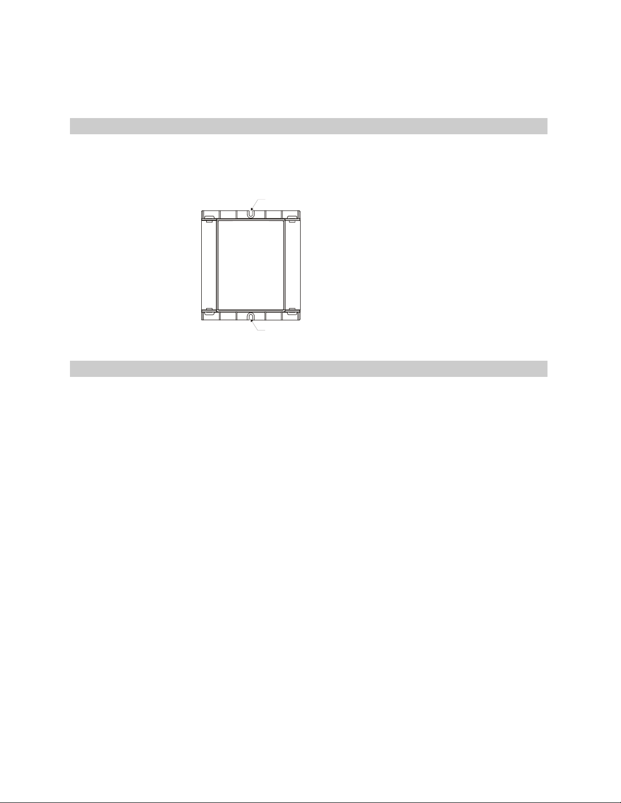
To mount the ZN551
measured from its input to ground and must share the same ground as the
control module.
Screw the ZN551 into an enclosed panel using the mounting slots provided
on the cover plate. Leave about 2 in. (5 cm) on each side of the control
module for wiring.
Mounting slo
Wiring for power
To wire for power
Mounting slo
CAUTIONS
• The ZN551 is a Class 2 device (less than 30 Vac, 100 VA). Take
appropriate isolation measures when mounting it in a control panel
where non-Class 2 devices (120 Vac or greater) are present.
• Do not power pilot relays from the same transformer that powers the
ZN551.
NOTE You can power several control modules from the same transformer if
you maintain the same polarity.
1 Remove power from the 24 Vac transformer.
2 Pull the screw terminal connector from the control module's power
terminals labeled Gnd and 24 Vac.
3 Connect the transformer wires to the screw terminal connector.
4 Apply power to the transformer.
5 Measure the voltage at the ZN551’s power input terminals to verify that
the voltage is within the operating range of 21.6–26.4 Vac.
6 Insert the screw terminal connector into the ZN551's power terminals.
7 Verify that the Power LED is on and the Run LED is blinking.
ZN551 Control Module • Rev. 3/17/2005 4 © 2005 Automated Logic Corporation
Page 5

10's1
To address the ZN551
You can address the ZN551 before or after you wire the control module for
power.
1 If the ZN551 has been wired for power, pull the screw terminal connector
2 Using the rotary switches, set the control module's address to match the
from the control module's power terminals labeled Gnd and 24 Vac. The
control module reads the address each time you apply power to it.
Address in the control module's Device Properties dialog box in
SiteBuilder. Set the Tens (10's) switch to the tens digit of the address,
and set the Ones (1's) switch to the ones digit.
EXAMPLE If the control module’s address is 35, point the arrow on the
Tens (10's) switch to 3 and the arrow on the Ones (1's) switch to 5.
's
Wiring for communications
The ZN551 communicates using BACnet on the following types of network
segments:
• ARC156 communicating at 156 kbps
• MS/TP communicating at 9600 bps, 19.2 kbps, 38.4 kbps, or 76.8 kbps
NOTE ARC156 is a unique implementation of the industry standard
ARCNET. For a summary of differences between ARCNET and ARC156, see
the ARC156 Wiring Technical Instructions (http://info.automatedlogic.com).
Wiring specifications
To wire the ZN551 for communications
For... Use... Maximum Length
ARC156
MS/TP
* See the ARC156 Wiring Technical Instructions (http://info.automatedlogic.com).
1 Pull the screw terminal connector from the control module's power
terminals labeled Gnd and 24 Vac.
2 Check the communications wiring for shorts and grounds.
3 Connect the communications wiring to the control module’s screw
terminals labeled Net +, Net -, and Shield.
NOTE Use the same polarity throughout the network segment.
22 AWG, low-capacitance, twisted,
stranded, shielded copper wire*
A dedicated 22 AWG to 18 AWG
twisted pair wire (EIA-485)
2000 feet (610 meters)
3000 feet (914.4 meters) for 9600
bps, 19.2 kbps, or 38.4 kbps
2000 feet (610 meters) for 76.8 kbps
ZN551 Control Module • Rev. 3/17/2005 5 © 2005 Automated Logic Corporation
Page 6

4 Set the communication type and baud rate.
For...
ARC156 ARC156 N/A. Baud rate will be 156 kbps
MS/TP MSTP The appropriate baud rate. See the MSTP
NOTE Use the same baud rate for all control modules on the network
segment.
5 Insert the power screw terminal connector into the ZN551's power
terminals.
6 Verify communication with the network by viewing a module status
report in WebCTRL.
Wiring inputs and outputs
Wire the ZN551's inputs and outputs as follows.
Wiring specifications
Input wiring
Input Maximum length Minimum gauge Shielding
Set Communications
Selection jumper to...
Set DIP switches 1 and 2 to...
regardless of the DIP switch settings.
Baud diagram on the control module.
0–5 Vdc
1000 feet
26 AWG Shielded
(305 meters)
Thermistor
Dry contact
RS room sensors
LogiStat
1000 feet
(305 meters)
500 feet
(152 meters)
100 feet
22 AWG Shielded
22 AWG,
4 conductor
22 AWG
2
1
Shielded or
unshielded
Unshielded
(30 meters)
1
See the RS Room Sensors Technical Instructions (http://info.automatedlogic.com).
2
See the LogiStat Sensors Technical Instructions (http://info.automatedlogic.com).
Output wiring
To size output wiring, consider the following:
• Total loop distance from the power supply to the control module, and
then to the controlled device
NOTE Include the total distance of actual wire. For 2-conductor wires,
this is twice the cable length.
• Acceptable voltage drop in the wire from the control module to the
controlled device
• Resistance (Ohms) of the chosen wire gauge
• Maximum current (Amps) the controlled device requires to operate
ZN551 Control Module • Rev. 3/17/2005 6 © 2005 Automated Logic Corporation
Page 7

To wire inputs and outputs
1 Verify that the ZN551's power and communications connections work
properly.
2 Pull the screw terminal connector from the control module's power
terminals labeled Gnd and 24 Vac.
3 Connect the input wiring to the screw terminals on the ZN551.
NOTE Connect the shield wire to the GND terminal with the ground
wire.
Any input
thermistor
Relay,
dry contact
+V
DC
power
supply
Gnd
4 To wire a room sensor to the ZN551, wire the ZN551's terminals to the
room sensor's terminals.
○ For an RS room sensor, wire each terminal on the ZN551's Rnet port
to the terminal of the same name on the RS room sensor.
NOTE If wiring an RS room sensor with shielded wire, connect the
shield wire to the GND terminal with the ground wire.
○ For a LogiStat room sensor, use the following table.
+V
Gnd
Out
0-5Vdc
Gnd
Any input
Gnd
Gnd
Wire this terminal
on the LStat port...
Gnd
IN-4
IN-5
LED
5 Set the appropriate jumpers on the ZN551.
To use... For...
IN-1 or IN-2 Thermistor
Dry contact
0–5 Vdc
IN-4 or IN-5 Thermistor
Dry contact
IN-4 and IN-5 LogiStat 1. Remove the jumper from LStat/IN-4.
Rnet Port RS sensor Set the LStat/Rnet jumper to Rnet.
ZN551 Control Module • Rev. 3/17/2005 7 © 2005 Automated Logic Corporation
To this terminal on
the LogiStat sensor
Gnd
Temp
SW
LS5v
Set jumpers IN-1 or IN-2 to the type of signal the
input will receive.
Verify the LStat/IN-4 jumper is on.
2. Set the LStat/Rnet jumper to LStat.
Page 8

LStat
Rnet
LStat
IN-4
IN-1
Thermistor/dry contact
0-5Vdc
IN-2
Thermistor/dry contact
0-5Vdc
6 Connect the digital output wiring to the screw terminals on the ZN551
and to the controlled device.
Any DO
Motor
Any DO
24 Vac or
Bus
24 Vdc
7 Connect the analog output wiring to the screw terminals on the ZN551
and to the controlled device.
Gnd
Motor
Any AO
+
0-10 V
Gnd
Valve
Any AO
+
0-10 V
NOTE Current from the analog outputs can drive a 20 mA device. To use
an analog output for this purpose, you may need to add a 1/2 watt
resistor in series with the device to achieve the required total resistance
of 500 Ohms. For example, to drive a device that has 100 Ohms of
resistance, wire a 400 Ohm resistor in series with the 20 mA device to
achieve 500 Ohms resistance.
8 Insert the power screw terminal connector into the ZN551's power
terminals.
ZN551 Control Module • Rev. 3/17/2005 8 © 2005 Automated Logic Corporation
Page 9

Downloading memory
Download memory to a control module to do either of the following:
• Send control programs, the module driver, editable properties, and
schedules to a control module for the first time. The first download takes
longer than subsequent downloads.
• Send changes such as a change to a control program, an upgrade to the
module driver, or a change to the control module's address.
The ZN551 can store one DRV_ZN module driver and one control program.
CAUTIONS
• The control module automatically halts before and restarts after a
memory download, causing the shutdown and restart of any equipment
controlled by the module.
• Downloading memory overwrites all control programs in the control
module causing it to lose stored data.
You download memory from WebCTRL. If your network is complete, you can
download from any network browser. If not complete, connect a laptop with a
local copy of the system database to the ZN551's local access port. See steps
1–3 of To communicate through the local access port (page 16).
To download memory in WebCTRL
1 On WebCTRL's CFG tree, click Download.
2 Select the Memory checkbox.
NOTE A memory download includes a Parameters and Schedules
download.
3 On the Network tree on the right, select the control module you want to
download to.
4 Click Add to add the control module to the Download Items list.
5 Click Download Selected Items.
If the download fails, the control module appears in the Failures box. Since
this indicates a system problem, do not clear the failure. Locate and resolve
the problem, then retry the download. To retry, select the control module in
the Failures box, then repeat steps 4 and 5 above.
To assign inputs or outputs to points
To use an input or output, you must assign it to its corresponding point in
the control program.
1 In WebCTRL's GEO tree, select the equipment controlled by the ZN551.
2 From the menu
, select Point Checkout.
ZN551 Control Module • Rev. 3/17/2005 9 © 2005 Automated Logic Corporation
Page 10

3 In the Num field for each point, type the number of the control module's
corresponding input or output. For example, if you use DO1 on the
ZN551 for the point Fan S/S, type 1 in the Num field for Fan S/S.
NOTE Exp (expander number) is 0 for the ZN551.
4 Enter the appropriate values for each input and output in the remaining
columns. See Input values, Output values, Resolution values and
Offset/Polarity values below.
NOTE You can also enter these values in EIKON for WebCTRL.
5 If you have not performed the initial memory download to the ZN551, you
must download now so you can verify inputs and outputs.
6 To verify each input's operation, force each sensor to a known value, then
compare it to the Value shown on the control program's Point Checkout
tool in WebCTRL.
7 To verify each output's operation, lock each output to a known condition
on the control program's Point Checkout tool in WebCTRL, then verify
that the equipment operates correctly.
Input values
Input I/O Type Sensor/Actuator Type Min/Max
Analog (BAI)
0–5 Vdc 0–5 Volt Linear Full Range
Engineering values
associated with 0 Vdc (Min)
and 5 Vdc (Max)1
Thermistor Thermistor
Select your Thermistor
N/A
type or set up and select
a Non-Linear, Custom
2
Table
Digital (Binary) (BBI)
Dry Contact Dry Contact N/A N/A
1
The sensor reads a value and sends a corresponding signal (Volt, mA, or psi) to the
ZN551's physical input. The Analog Input microblock uses the Min and Max values to
linearly translate the signal into the engineering value used in subsequent control logic.
For example, set Min to 0 and Max to 10 for a 4–20 mA sensor that measures velocity
from 0.0 to 10.0 inches/second so that when the input reads 4 mA, the microblock
outputs a value of 0. Similarly, when the input reads 8 mA, the microblock outputs a
value of 2.5.
2
To set up a custom translation table, see the module driver's Custom Translation Tables
properties page in WebCTRL.
Output values
Output I/O Type Sensor/Actuator Type Min/Max
Analog (BAO)
0–10 Vdc
Electrical
0–10 Volt
Linear Full Range
Engineering values
associated with 0 Vdc (Min)
and 10 Vdc (Max)1
2–10 Vdc
Electrical
0–10 Volt
ZN551 Control Module • Rev. 3/17/2005 10 © 2005 Automated Logic Corporation
Linear w/Offset,
2–10 Volts
Engineering values
associated with 2 Vdc (Min)
1
and 10 Vdc (Max)
Page 11

Output I/O Type Sensor/Actuator Type Min/Max
Digital (Binary) (BBO)
Resolution values
Relay
1
The Analog Output microblock uses the Min and Max values to linearly translate its
EIKON for WebCTRL wire value into a physical output signal (Volt, mA, or psi) sent from
the ZN551 to an actuator. For example, set Min to 0 and Max to 100 for an Analog
Output microblock that receives a 0 to 100% open signal from a PID microblock and
that controls a 0–10 Vdc actuator so that when the PID signal is 100%, the ZN551
output is 10 Vdc. Similarly, when the PID signal is 50%, the ZN551 output is 5 Vdc.
Resolution is not particular to a type of input or output, but the module
driver handles analog and digital (binary) inputs and outputs differently. To
set these values appropriately, you should understand how the module driver
uses them.
Resolution Notes
Analog Input (BAI)
Analog Output (BAO)
Digital Inputs and
Outputs
Relay/Triac
Output
N/A N/A
The driver truncates the microblock's present value according
to the resolution.
EXAMPLE If the calculated present value is 13.789 and you
set the Resolution to 0.1, the control program uses 13.7 for
any calculations downstream from the microblock.
The driver truncates the wire input value to the microblock
before performing any scaling calculations.
EXAMPLE If the wire input value is 13.789 and you set the
Resolution to 0.1, the microblock uses 13.7 for any scaling
calculations.
N/A
Offset/Polarity values
ZN551 Control Module • Rev. 3/17/2005 11 © 2005 Automated Logic Corporation
Offset/Polarity is not particular to a type of input or output, but the module
driver handles analog and digital (binary) inputs and outputs differently. To
set these values appropriately, you should understand how the module driver
uses them.
Offset/Polarity Notes
Analog Input (BAI)
Analog Output (BAO)
Offset value (positive or negative) adds a fine adjustment to a
sensor reading after all scaling for calibration.
EXAMPLE If a sensor reads 74.9°F when the actual
measured value is 73.6°F, enter an Offset of –1.3 to
calibrate the sensor to the measured value.
You can use the Offset value (positive or negative) to
calibrate an output, but you generally do not need to. If used,
the driver adds the offset value to the wire input value before
performing any scaling calculations to determine the ZN551's
output.
Page 12

Offset/Polarity Notes
Using flow sensors
Digital (Binary) Input
(BBI)
Digital (Binary) Output
(BBO)
In a single duct system, the ZN551 controls airflow in the zone using a USF
flow sensor and an actuator connected to two digital outputs.
In a dual duct system, the ZN551 controls airflow in the zone using a UDF
flow sensor and two actuators, with each actuator connected to two digital
outputs.
Polarity determines the microblock's present value when no
signal is received from the equipment.
When no signal is received from the equipment, if Polarity is
set to:
normal—present value is off
reversed—present value is on
Polarity determines the ZN551's output based on the control
program's signal to the microblock.
When the control program's signal to the microblock is on, if
Polarity is set to:
normal—output is on
reversed—output is off
NOTE Regardless of Polarity, the output will be off if the
ZN551 loses power.
To connect the duct tubes to the flow sensors
To wire the flow sensor to the control module
To set up the Airflow Control microblock
USF
1 Connect the duct’s total pressure tube to the USF's High connector.
2 Connect the duct’s static pressure tube to the USF's Low connector.
UDF
Follow the procedure for a USF, but connect one duct's tubes to the UDF's
Flow #1 connectors and the other duct's tubes to the UDF's Flow #2
connectors.
Use the cable included with the flow sensor (ALC part #235012) or a 20 AWG,
4-conductor cable, maximum length 4 feet (1.22 meters).
1 Turn off the control module's power.
2 Connect the ends of the cable to the 4-pin connector on the flow sensor
and to the 4-pin connector on the control module.
The ZN551's control program must include one Airflow Control microblock
for a single duct system or two of the microblocks for a dual duct system.
You must set up the Airflow Control microblock for each flow sensor.
ZN551 Control Module • Rev. 3/17/2005 12 © 2005 Automated Logic Corporation
Page 13

For a single duct system
1 In WebCTRL, on the control program's Logic page, select the U-Line
Airflow Control microblock.
2 On the Details tab in the Flow Sensor field under Hardware
Configuration, select External flow sensor.
3 In the Input Number field, type 1.
4 In the I/O Type field, select Flow Input.
5 At the bottom of the Details tab, click the plus sign (+) to the left of Flow
Input (AI) Configuration.
6 In the Sensor Type field under Calibration, select No Translation.
For a dual duct system
1 In WebCTRL, on the control program's Logic page, select the Airflow
Control microblock for Flow #1.
2 On the Details tab in the Flow Sensor field under Hardware
Configuration, select External flow sensor.
3 In the Input Number field, type 1.
4 In the I/O Type field, select Flow Input.
5 At the bottom of the Details tab, click the plus sign (+) to the left of Flow
Input (AI) Configuration.
6 In the Sensor Type field under Calibration, select No Translation.
7 On the Logic page, select the airflow control microblock for Flow #2.
8 Repeat steps 2 through 6 for Flow #2, typing 2 in step 3.
NOTE When performing test and balance, follow the steps under Test and
Balance on the Airflow Control microblock's Properties page Details tab in
WebCTRL.
To set up the module driver
After you download the module driver and control program to the ZN551, you
may want to change the module driver's properties to suit your application.
1 On WebCTRL's NET tree, click the plus sign (+) to the left of your ZN551.
NOTE Driver properties are on the Driver Properties page and on its
children in the tree.
2 Click the page you want to view, then change properties as needed.
Driver
On this page, you can change the following properties:
• Module clock synchronization and failure. See table below.
• Network Input microblock communication properties.
ZN551 Control Module • Rev. 3/17/2005 13 © 2005 Automated Logic Corporation
Page 14

Module Clock
Device
Notification Class #1
Clock Fail Date and Time
Time Synch Sensitivity
(seconds)
On this page, you can change the following properties:
• BACnet device object properties for the ZN551
• ZN551 network communication
Configuration
Max Masters and Max Info
Frames
WebCTRL alarms use Notification Class #1. A BACnet alarm's Notification
Class defines:
Date and time control program uses when module's realtime clock is invalid.
TIP Use an occupied date and time (such as a Tuesday
at 10 a.m.) so the equipment does not operate in
unoccupied mode if the module loses power during
occupancy.
On a Time Synch signal, update the module clock only if
the module time differs from the signal time by more
than this value.
NOTE The three APDU fields refer to all networks over
which the ZN551 communicates.
Apply only if the ZN551's parent network is an MS/TP
network.
• Alarm priority for Alarm, Fault, and Return to Normal states
• Options for BACnet alarm acknowledgement
• Where alarms should be sent (recipients)
NOTE You may need to set up additional Notification Classes if your system
will handle Life Safety alarms or if you need to send certain types of alarms
only to an alarm manager other than WebCTRL.
Priorities
Priority of Off-Normal BACnet priority for Alarms.
Priority of Fault BACnet priority for Fault messages.
Priority of Normal BACnet priority for Return-to-normal messages.
NOTE BACnet defines the following Network message
priorities for Alarms and Events.
Priority range Network message priority
00–63 Life Safety
64–127 Critical Equipment
128–191 Urgent
192–255 Normal
ZN551 Control Module • Rev. 3/17/2005 14 © 2005 Automated Logic Corporation
Page 15

Ack Required for Off-Normal,
Fault, and Normal
Recipient List
Recipients
Recipient Description Name that appears in the Recipients table.
Recipient Type
Recipient Device Object
Identifier
Process Identifier
Issue Confirmed
Notifications
Requires a control module acknowledgement for each
message type. Normally not required.
TIP To require operator acknowledgement for an Alarm
or Return-to-normal message (stored in the WebCTRL
database) change the acknowledgement settings on
WebCTRL's Alarm > Enable/Disable tab for an alarm
source or an alarm category.
The first row in this list is the WebCTRL Server. Do not
delete this row. Click Add if you want other BACnet
devices to receive alarms.
Use Address (static binding) only for third-party BACnet
device recipients that do not support dynamic binding.
Type the Device Instance from SiteBuilder (or from the
network administrator for third-party devices) in the #
field.
Change for third-party devices that use a BACnet Process
Identifier other than 1. WebCTRL processes alarms for
any 32-bit Process Identifier.
Select to have a device continue sending an alarm
message until it receives delivery confirmation from the
recipient.
Common Alarms
On these pages, you can change the following control module alarm
properties:
• BACnet alarm object properties
• Enable/disable
• Delays
NOTE To set up alarm actions for control module generated alarms, see
Setting up alarm actions in WebCTRL Help.
Module Generated Alarm
Description
Events
Alarm Category and Alarm
Template
Enable
Notification Class Do not change this field.
Short message shown on WebCTRL's Alarm page or in an
alarm action when this type of alarm is generated.
See Customizing alarms in WebCTRL Help.
Clear these checkboxes to disable Alarm or Return to
normal messages of this type from this control module.
Custom Translation Tables
ZN551 Control Module • Rev. 3/17/2005 15 © 2005 Automated Logic Corporation
On the Custom Translation Table pages, you can edit the tables used to
translate raw sensor data to engineering units for inputs associated with
Non-Linear, Custom Table sensor/actuator types.
Page 16

t
To communicate through the local access port
Using a computer and an APT, you can communicate locally with the ZN551
to download memory or to troubleshoot.
PREREQUISITES
• A computer with an RS232 port
• An APT with cables. See the APT Technical Instructions
(http://info.automatedlogic.com).
1 Connect the computer to the APT, and then the APT to the control
module.
9-pin
APT cable
Connect to the
control module’s
Local Access por
Rnet
adapter
cable
To set up a Local Access connection in WebCTRL
8-pin
APT cable
2 Set the APT's Mode Select switch to 485.
3 Set the APT's Exec. 4 Relay switch to Network.
1 On the CFG tree, select Connections.
2 On the Configure tab, click Add.
3 From the Type drop-down list, select BACnet Local Access.
4 Optional: Edit the Description.
5 Type the computer's Port number where your APT is connected.
6 Set the Baud rate to 115200.
7 Click Accept.
8 On the View tab, click the drop-down arrow next to your device's
network Connection, then select BACnet Local Access.
9 Click Accept.
10 On the Configure tab, select BACnet Local Access, then click Start.
Troubleshooting
If you have problems mounting, wiring, or addressing the ZN551, contact
ALC Technical Support.
ZN551 Control Module • Rev. 3/17/2005 16 © 2005 Automated Logic Corporation
Page 17

Formatting the control module
LED's
If you cannot communicate with a control module after downloading memory
to it, as a last resort, you can manually format the control module to erase its
memory.
1 Pull the screw terminal connector from the control module's power
terminals labeled Gnd and 24 Vac. Make sure the address switches are
not set to 0, 0.
2 Short the Format jumper’s pins.
3 Insert the power screw terminal connector into the ZN551's power
terminals.
4 Continue to short the jumper until the Error LED flashes three times in
sync with the Run LED.
5 Remove the short.
6 Download memory to the ZN551.
The LED's on the ZN551 show the status of certain functions.
If this LED is on... Status is...
Power The ZN551 has power
Rx The ZN551 is receiving data from the network segment
Tx The ZN551 is transmitting data over the network segment
DO# The digital output is active
The Run and Error LED's indicate control module and network status.
If Run LED shows... And Error LED shows... Status is..
2 flashes per second Off Normal
2 flashes per second
2 flashes per second
2 flashes per second
2 flashes per second On
5 flashes per second On
5 flashes per second Off
7 flashes per second
2 flashes,
alternating with Run LED
3 flashes,
then off
4 flashes,
then pause
7 flashes per second,
alternating with Run LED
Five minute auto-restart delay
after system error
Control module has just been
formatted
Two or more devices on this
network have the same
ARC156 network address
Exec halted after frequent
system errors or control
programs halted
Exec start-up aborted, Boot is
running
Firmware transfer in
progress, Boot is running
Ten second recovery period
after brownout
ZN551 Control Module • Rev. 3/17/2005 17 © 2005 Automated Logic Corporation
Page 18

If Run LED shows... And Error LED shows... Status is..
Manufacture date
Compliance
14 flashes per second
When troubleshooting, you may need to know a control module's
manufacture date.
Obtain the manufacture
date from a...
Module status report (modstat) To obtain a modstat in WebCTRL:
Sticker on the back of the
main control module board
14 flashes per second,
alternating with Run LED
Notes
1. Select the control module in the NET tree.
2. Press Ctrl+M.
3. Type modstat.
4. Click OK.
The report shows the date under Main board
hardware.
The first three characters on the sticker show the
control module type. The next three characters
show the year, month, and day of manufacture.
(The month digit is in hexadecimal format.)
Brownout
This equipment has been tested and found to comply with the limits for a
Class A digital device, pursuant to Part 15 of the FCC Rules. These limits are
designed to provide reasonable protection against harmful interference when
the equipment is operated in a commercial environment. This equipment
generates, uses, and can radiate radio frequency energy and, if not installed
and used in accordance with the instruction manual, may cause harmful
interference to radio communications. Operation of this equipment in a
residential area is likely to cause harmful interference in which case the user
will be required to correct the interference at his own expense.
CAUTION Changes or modifications not expressly approved by the
responsible party for compliance could void the user’s authority to operate
the equipment.
ZN551 Control Module • Rev. 3/17/2005 18 © 2005 Automated Logic Corporation
 Loading...