

Page 1

T-Line (TNI v4.7)
Technical Instructions
Contents
Description ................................................................................................... 3
Specifications .............................................................................................. 3
Point Capacity.............................................................................................. 4
Limitations ................................................................................................... 5
T-Line Modules Not For Time Critical Applications............................ 5
Trending................................................................................................. 5
T-Line Mounting........................................................................................... 5
Addressing ................................................................................................... 6
Virtual Modules...................................................................................... 6
Default Algorithm Downloader............................................................. 6
Power and Communication Wiring............................................................. 8
Important Notice................................................................................... 8
Calculating Wire and Transformer Requirements for a
Bus Power Wiring Configuration ................................................... 9
T-Line Module Wiring .......................................................................... 10
Adding T-Line Modules ............................................................................. 14
Hardware Procedure ........................................................................... 14
Software Procedure ............................................................................ 14
Zone Sensor Wiring ................................................................................... 14
Standard Zone Sensor ........................................................................ 14
(Using the Enhanced Zone Sensor Port) ........................................... 14
Enhanced Zone Sensor....................................................................... 14
Using the Enhanced Zone Sensor............................................................ 15
Local Setpoint Adjust ......................................................................... 15
Timed Local Override.......................................................................... 16
Occupancy Indication ......................................................................... 16
Local Access (Optional) ............................................................................ 16
Procedure ............................................................................................ 16
Input Wiring................................................................................................ 17
Table 1: Input Wiring Guidelines....................................................... 17
Procedure ............................................................................................ 17
Custom Translation Tables....................................................................... 18
Procedure ............................................................................................ 18
Channel Numbers ...................................................................................... 20
Table 2: T540 and T320 Module Outputs .......................................... 20
Table 3: T540v and T320v Module Outputs ...................................... 21
Table 4: All T-Line Module Inputs ..................................................... 22
Digital Output Wiring ................................................................................. 23
Connecting the Flow Sensor
(T320V, T540V only) ............................................................................ 23
Calibrating the Flow Sensor ..................................................................... 23
Adjusting the Zero Point..................................................................... 23
Parameter Page.......................................................................................... 24
Applies to models:
T320 T320v T540 T540v
Rev. (29-JUN-99) • TNI v4.7
1
©1995-99 Automated Logic Corporation
Page 2

Status Page ................................................................................................ 24
Adjusting the Flow Sensor Gain ........................................................ 25
Checkout & Troubleshooting.................................................................... 25
Downloading Memory ............................................................................... 25
LEDs ........................................................................................................... 26
LED Power-up Sequence .................................................................... 26
Fuses .......................................................................................................... 26
Production Date ......................................................................................... 27
Using Quick-Disconnects ......................................................................... 27
Crimping & Terminating Quick-Disconnects .................................... 27
Removing Quick-Disconnects............................................................ 28
Rev. (29-JUN-99) • TNI v4.7
2
©1995-99 Automated Logic Corporation
Page 3

Description
Specifications
The T-Line is part of the I/O Hardware family of control
modules and is designed specifically for zone control.
The T-Line consists of the T320, T320v, T540, and
T540v ("v" indicates the board has a flow sensor). A
single main board provides the power circuitry, the
microprocessor, and nonvolatile memory. The name of
the module indicates the number of outputs and inputs
which it provides. The T-Line modules are designed to
be mounted directly on the equipment being controlled,
such as VAV boxes, heat pumps, unit ventilators, and fan
coil units.
Each T-Line module communicates with the CMnet
through a Tnet Interface module (TNI) (see Figure 6).
Each T-Line module can store an optional default
algorithm (see T-Line Default Algorithm Downloader TI
for more information) which maintains the space
temperature in the event that communications is lost with
the TNI module.
Each T-Line module is associated with a single T-Line
Graphic Function Block (GFB) downloaded into the TNI
module. Sample T-Line GFBs are available from the
BBS which can be used as a starting point for
customizing the GFBs for your specific application.
However, before customized FBs can be downloaded,
they must be made in Eikon according to the Zone GFBs
standards. The small percentage of Zone GFBs which
can not be made in Eikon can be reviewed and encrypted
by Dealer Services.
NOTE: To operate this module based on a schedule, it
must be networked with a Gateway module.
Power: 24 VAC ±10%, 50-60 Hz, 2.4 VA (0.10A)
maximum.
Inputs: T320/T320v - (2) Dry contact or thermistor.
T540/T540v - (4) Dry contact or thermistor, two of which
can be configured as 0-5 VDC.
Custom translation tables allow nonstandard signals.
If used, the RSZ+ requires 2 inputs.
Outputs: (T320,T320v = 3; T540, T540v = 5): Digital
outputs, rated 1 Amp @ 24 VAC. See Figure 2 for
allowable configuration.
Flow Sensor: (T320v, T540v only) Range of 0-2" w.c.,
0.003" wc resolution.
Status Indicator: LED indicators for visual status of
receive, transmit/run, and each output.
Communications: EIA-485 port for communicating
on the Tnet.
Memory (T-Line): Non-volatile storage of default
control algorithm.
Memory (TNI): 128k bytes of non-volatile storage
divided into 8 banks of 16k per module (virtual and real).
Protection: Bussed output relays to eliminate phasing
problems, surge protection on network lines and on input
power, arc suppression on relays. (Use the Optional
T-net Protection Board (TNPB) which is available for
additional network surge protection.)
4"
Rev. (29-JUN-99) • TNI v4.7
61/2"
37/8"
Figure 1: T540 Top and Side View Dimensions
3
©1995-99 Automated Logic Corporation
11/2"
Page 4

Fault Detection: Hardware watchdog timer.
Temperature: Operating temperature range is 0-130 °F
(-17.8 to 54.4 °C), non-condensing.
Dimensions: (T320, T540) 4" x 4" x 1 1/2"
(T320V, T540V) 5" x 4" x 1 7/8".
Point Capacity
No. of DO
T320v 3 2 0-2" WC
No. of
AI/DI*
Velocity
Pressure
A/D Input Resolution: 10 bit.
Processor: Microchip PIC16C57, 11.06 MHz, 2k
ROM, 72 bytes RAM.
Listed by: PAZX (UL 916).
Allowable Digital Outputs
T540* T540V* T320 T320V
Start/Stop 1,2,3,4,5 3,4,5 1,2,3 3 only
T320 3 2 --
T540v 5 4 0-2"WC
T540 5 4 --
* Two inputs (the only inputs on the T320 and
T320v) may be accessed through the enhanced
sensor port using an Insulation Displacement
Connector (IDC). If used, the Enhanced Zone
Sensor (RSZ+) will require two of the available
inputs.
Pulse Width
Modulation 1,2,3,4 3,4 1,2,3 3 only
FM Output 1 -
Open 1 3 1 none
Close 2 4 2 none
FM Output 2 -
Open 3 none none none
Close 4 none none none
VAV Flow
Output** -
Open none 1 none 1
Close none 2 none 2
* - Digital output 5 can only be used for start/stop control.
** - Digital outputs 1 and 2 can only be used for VAV Flow control on the
T540v and T320v.
Figure 2: Allowable T-Line Digital Output Configuration
Rev. (29-JUN-99) • TNI v4.7
4
©1995-99 Automated Logic Corporation
Page 5
Limitations
1. No pulse accumulation inputs are allowed on T-Line
FBs, except for the TLO button reserved for the
enhanced zone sensor (RSZ+).
2. The TLO button on the RSZ+ can only be connected
to Universal Input #2 on the T-Line's enhanced zone
sensor port (pin 3).
Trending
Using virtual modules to increase the number of FBs in
the TNI decreases the memory available for trending. If
all 40 FBs are used, only a very limited number of points
can be trended. No enhanced trending capabilities are
available.
3. For T540 and T540V, digital output 5 can only be
used for start/stop control.
4. Digital outputs 1 and 2 can only be used for VAV
Flow Control on the T540v and T320v.
Figure 2 lists the possible output configurations of the
T-Line modules.
T-Line Modules Not For Time Critical
Applications
T-Line modules have been designed to meet low-end,
high-volume terminal control applications. As a result,
time-critical applications (such as short time delays and
trend intervals of less than one minute) should not be used
with these modules. ALC recommends that all time delay
functions and trend intervals on T-Line FBs be set to
greater than or equal to 1 minute.
No pulse accumulation inputs are allowed on T-Line FBs,
except for the TLO button reserved for the ALC enhanced
zone sensor (RSZ+).
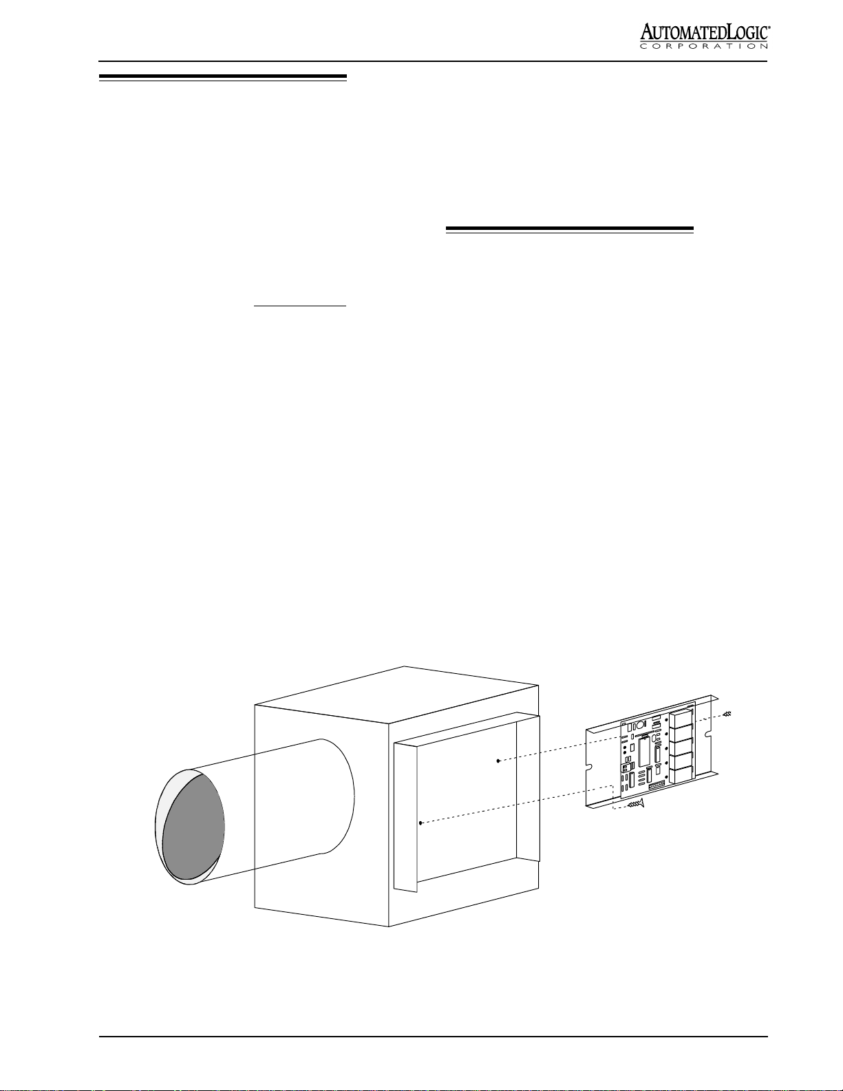
T-Line Mounting
NOTE: Before mounting any T-Line board, make note
of the board's I.D. number. The board I.D. number can be
found on the large 28 pin integrated circuit (I.C.) (see
Figure 5).
1. Remove the T-Line board from the Snap-Track.
2. Position the Snap-Track in a convenient location,
providing at least 1½" clearance on each side for
wiring purposes. Mount by using self-drilling screws
and drill directly into the plastic near the edges of the
Snap-Track so that the screws will be visible when
the T-Line board is installed (see Figure 3). This
prevents loose screws from shorting out the back of
the T-Line Board.
3. Mount the T-Line board on the Snap-Track by
pushing it firmly into the grooves.
Rev. (29-JUN-99) • TNI v4.7
VAV BOX
Figure 3: Mounting a T-Line Module
5
T540 MODULE
©1995-99 Automated Logic Corporation
Page 6
Addressing
T-Line modules are not addressed by dip switches;
instead they are programmed with an I.D. number at the
factory. The board I.D. number can be found on the large
28 pin I.C. Enter this number on the parameter page of
the TNI Function Block (FB #15). See Parameter Page
on page 24.
Virtual Modules
NOTE: The use of virtual modules decreases the
memory available for trending.
use the maximum of 40 GFBs per TNI, the TNI will use
the real module and at least three virtual modules to store
GFBs.
In some cases, a module (real or virtual) will not support
10 GFBs due to the size of the GFBs. For those cases, it
is necessary to add one or more virtual modules and
distribute the GFBs among them. For example, a TNI
may contain 8 modules (1 real and 7 virtual), each
containing 5 GFBs (8 x 5 = 40). Some room should be
left in the physical module's memory for enhancement
and features to be added to the module driver. See the
section "Adding T-Line Modules" for more information
on hardware and software procedures.
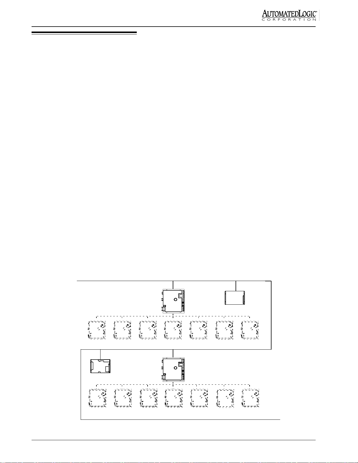
As shown in Figure 4, a TNI has the capability of acting
as one real module and seven virtual modules. This
allows one TNI to have a total of eight addresses either in
sequence or not. Each module (real or virtual) contains
16k bytes of memory. Virtual modules are addressed on
the module driver (FB #15) parameter page. The virtual
module addresses do not have to be contiguous if the TNI
exec is 4.07 or higher. The TNI itself (real module) is
physically addressed using the hardware dip switches.
TNI modules allow for the use of virtual modules in order
to increase the maximum number of GFB's that may exist
in each TNI (see Figure 4). Each TNI virtual module is
an addressable node on the CMnet that may contain up to
10 GFBs (if memory allows) and one module driver (FB
#15) as long as the maximum of 40 GFBs per TNI
module (including virtual modules) is not exceeded. To
CMnet - Maximum 700 GFBs
address = 10
The CMnet can support up to 100 control modules (1 FB
each) and 700 GFBs (not including module drivers) for a
total of 800 FBs.
Default Algorithm Downloader
NOTE: For more information, please reference the
T-Line Default Algorithm Downloader TI (part no.
TITDAD).
Each T-Line module has the capability of storing a
default algorithm which maintains the space temperature
in the event that communications are lost with the TNI
module.
NOTE: Each T-Line FB uses channel 27 to indicate
whether communications are good (DI=ON) or bad
(DI=OFF).
TNI
Real
module
address = 18
G4106e
Virtual
Modules
address = 27
Rev. (29-JUN-99) • TNI v4.7
11 12 13
G4106e
address = 19
2526 23 22
Figure 4: Addressing the TNI
14 15
16
17
TNI
Real
module
Virtual
24
21
Modules
20
CMnet
6
©1995-99 Automated Logic Corporation
Page 7

VAV Flow
Sensor *
Tnet
Universal **
Inputs
Sensor Inputs
Grounds
Tnet
Fuses
Power
Jumper
HI
LO
+
IN1
-
IN2
IN3
24 VDC
GND
1.1
V
18315
IN4
Input Jumpers **
* - Not present on T540 and T320 models
** - Not present on T320v and T320 models
T-card Address
1
2
3
4**
5**
Enhanced Zone Sensor
Port (UI’s 1 & 2)
Output
Bus
Digital
Outputs
TNI
Tnet
TNPB
CMnet
Figure 5: T540v module layout
Maximum 100 Control Modules
R683
Maximum 40T-LineModulesPerTNI
Maximum 20 Modules Before REPOPT
T-Mod
1500 ft. Maximum Length of Tnet Wire
before REPOPT
T-Mod
G8102 Z540v
T-Mo d
RSZ+RSZ+
Maximum 20 Modules
Beyond REP OPT
REPO PT
1500 ft. Maximum Length
of Tnet Wire after REPOPT
(Distance c an be extended
with additional REPOPTs)
TNPB
RSZ+
Rev. (29-JUN-99) • TNI v4.7
Figure 6: Tnet Architecture
7
©1995-99 Automated Logic Corporation
Page 8

The T-Line Default Algorithm Downloader is a
communications program which enables you to download
default algorithms from your computer directly to the
T-Line modules. The computer connects with the T-Line
modules through an Opto Repeater or Tnet Adapter.
Refer to the T-Line Default Algorithm Downloader
Technical Instructions for more details.
Power and Communication Wiring
1. Connect the 24 VAC power wires to a single T-Line
module as described in the following steps.
a. Terminate AC power at the wiring source
(usually a circuit breaker or other AC source).
b. Terminate power to the high voltage side of the
transformer.
c. Remove the T-Line's power jumper (see Figure
5). This prevents the module from being
powered up until proper voltage is verified.
Important Notice
Avoid damaging the T-Line modules
communication circuits.
• IF you have multiple T-Line modules powered
by the same transformer,
OR
• IF you have multiple T-Line modules powered
by separate transformers, but have their grounds
connected (either through wires or through
conduit),
THEN you must observe the same polarity on the
T-Line modules’ AC-power connections.
CAUTION: The T-Line modules are Class 2 devices
(less than 30 VAC). Take appropriate isolation
measures when mounting a T-Line module in a control
panel where Class 1 devices or wiring are present.
NOTE: If wiring the T-modules together in a bus power
configuration (several T-modules sharing a single
transformer as shown in Figure 8), care must be taken in
the wiring and transformer sizing. The average current
value for a T-module is 100 mA (0.1 Amps), but the peak
current value for a T-540v with all outputs on is 670 mA.
Therefore, the wire and transformer must be sized larger
than apparent from the averaged value of the module VA
rating. See Figure 7 on calculating wire and transformer
requirements for a bus power configuration.
NOTE: To protect the Tnet communication wires,
ALC highly recommends installing TNPBs at the
beginning and end of each Tnet leg as shown in Figure
6.
d. Terminate the two power wires to the 24 VDC
and GND terminals indicated in Figure 5. Note
the polarity. See "Using Quick Disconnects"
later in this document for guidelines.
e. Verify that 24 VAC is present at the power input
and replace the power jumper.
2. Connect the Tnet communication wires to the same
T-Line module as described in the following steps.
a. Remove the module's power jumper.
b. Check the Tnet communication wiring for shorts
and grounds.
c. Terminate the Tnet communication wires to the
Tnet screw terminals indicated in Figure 5.
Note the polarity of the Tnet wires coming
from the TNPB.
d. Replace the module's power jumper.
3. Go to the next T-Line module on the Tnet and
connect the AC power wires as in step 1, using the
same polarity as on the first T-Line module. Do not
connect the communication wires yet.
4. To check for proper power polarity, measure the AC
voltage between one of the communication wires and
one of the communication terminals. If the AC
voltage is greater than 5 VAC, reverse the T-Line
module’s power wires and remeasure.
• If the voltage is still greater than 5 VAC, then
check for one of the improper wiring
configurations on page 12. Rewire the T-Line
modules according to one of the figures on
page 10 and remeasure.
NOTE: Whenever possible, terminate and verify power
and communications to all modules before terminating
any inputs or outputs.
BEFORE wiring power or communications to any
T-Line modules on the Tnet, use the following procedure.
Rev. (29-JUN-99) • TNI v4.7
8
©1995-99 Automated Logic Corporation
Page 9
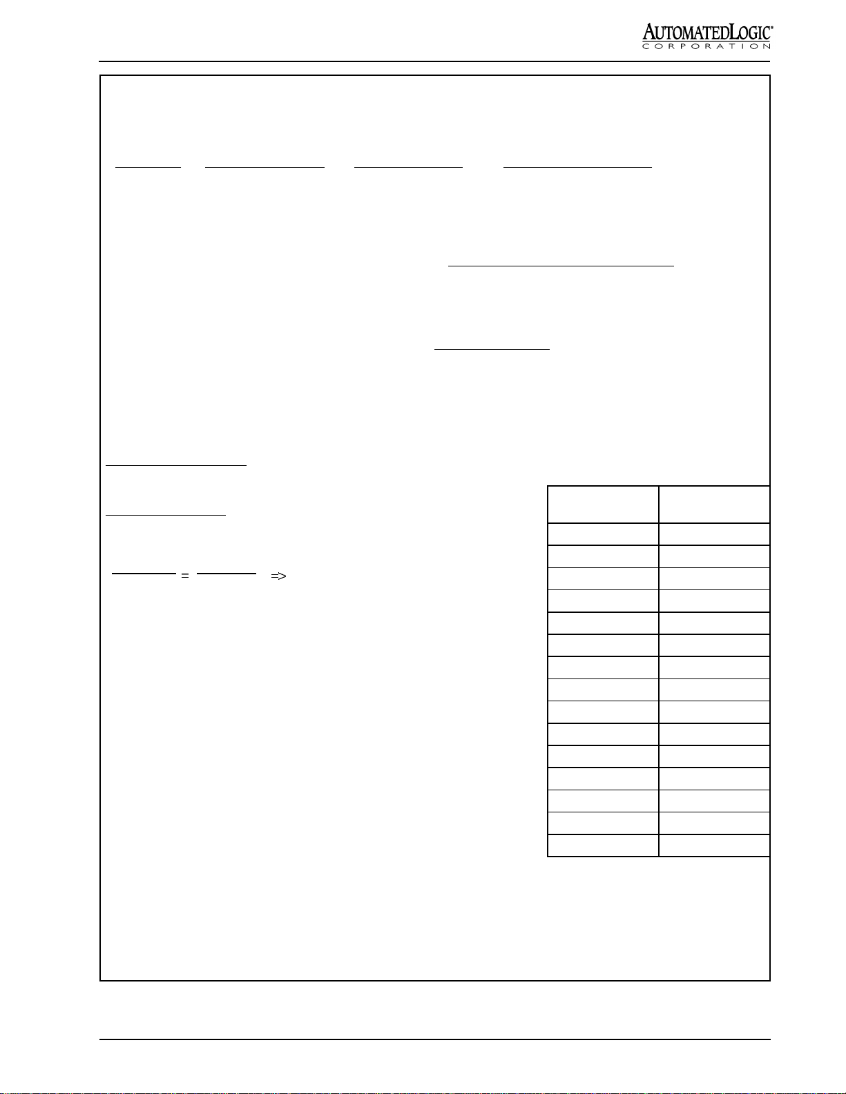
Calculating Wire and Transformer Requirements for a
Bus Power Wiring Configuration
BB
oard Typeoard Type
B
oard Type
BB
oard Typeoard Type
Max. Peak CurrentMax. Peak Current
Max. Peak Current
Max. Peak CurrentMax. Peak Current
Average CurrentAverage Current
Average Current
Average CurrentAverage Current
(Fluke model 77)(Fluke model 77)
(Fluke model 77)
(Fluke model 77)(Fluke model 77)
True RMS CurrentTrue RMS Current
True RMS Current
True RMS CurrentTrue RMS Current
(Beckman model 4410)(Beckman model 4410)
(Beckman model 4410)
(Beckman model 4410)(Beckman model 4410)
T540/T540v 0.670 A 0.176 A 0.117A (all outputs on)
T320/T320v 0.575 A 0.148 A 0.095 A (all outputs on)
To avoid excessive voltage drops, use the following formula (copper wire):
Wire Resistance =
(# of T-modules) * (max. peak current)
5 V drop allowed
Example: Six T540v modules
1.24 Ohms =
5 Volts
6 * 0.670 A
The above formula and resulting values in feet are conservative and do not take into account the decreased current as
the wire pair extends past each module.
From the above Formula:
The total resistance allowed when wiring six T540v modules = 1.24 ohms
From the Wire Table:
12 AWG wire has a resistance of 1.588 ohms per 1000 feet.
1.588 Ohms
1000 ft
1.24 Ohms
X
1.588 X = 1240 => X = 780.85 ft.
Thus, you can use a total of 780 ft. of 12 AWG wire to
connect the six T540v modules. This means that you can
run a pair of wires to the modules a distance of 390 ft.,
after that distance you will need to add another
transformer.
The sizing of the transformer should be adjusted to
compensate for the non-sinusoidal waveshape of the
current requirements. The VA rating of the T-module
should be multiplied by three (3) when computing
multiple T-modules being supplied by one transformer.
Example: Six T540 modules
(6 modules) ∗ (2.4 VA per module ∗ 3) = 43 VA
Gauge No. (AWG)
Wire Table
Ohms per 1000 ft
at 20 C (= 68 F)
10 0.9989
11 1.260
12 1.588
13 2.003
14 2.525
15 3.184
16 4.016
17 5.064
18 6.385
19 8.051
20 10.15
21 12.80
22 16.14
23 20.36
24 25.67
(A 40 VA transformer would be reasonable since all
outputs would not be on simultaneously.)
Figure 7: Calculating Wire and Transformer Requirements for a Bus Power Configuration
Rev. (29-JUN-99) • TNI v4.7
NOTE: Resistances shown in the table above are for
solid wire only. If you are using stranded wire, refer to
the wire manufacturer’s specifications to determine the
proper resistances.
9
©1995-99 Automated Logic Corporation
Page 10

PR I
SEC
24VAC
T-Line Module Wiring
RIGHT
POLARITY IS
IMPORTANT
EQUIPMENT
GROUND
BONDED TO
EARTH
GROUND
T-modT-mod
ISOLAT ED
LOAD
COM M LINE
TW ISTE D PAIR
(POLARITY IS IMPORTANT)
ISO L A T E D
LOA D
Figure 8: Multiple T-Line modules powered by the same transformer, grounded to Earth Ground
PRI
SEC
24VAC
EQUIPMENT
GRO U ND
BONDED TO
EAR T H
GRO U ND
IS O LA T ED
LOA D
COMM LINE
TWISTED PAIR
PRI
SEC
24V AC
T-modT-mod
(POLA R I TY IS IM P OR TA NT)
ISO LAT E D
LOAD
Figure 9: Multiple T-Line modules powered by separate transformers
PRI
SEC
24V AC
PRI
SEC
24VA C
T-mod T-m od
EQUIPMENT
GROUND
BONDED TO
EARTH
GROUND
IS OLATED
LOA D
COMM LINE
TW ISTED PAIR
(POLARITY IS IMPORTANT)
EQUIPMENT
GROUND
BONDED TO
EARTH
GROUND
ISO LA T ED
LOAD
Figure 10: Multiple T-Line modules powered by separate transformers, each grounded to Earth Ground
Rev. (29-JUN-99) • TNI v4.7
10
©1995-99 Automated Logic Corporation
Page 11

(
)
TNI
24 VAC
GND
+
NET
-
GND
T-net Protection Board
TNPB
+
NET
T-Board
24 VAC
OUT
Bussed
GND
Power
24 VAC 2 4 VAC
T-net
Load
Independent Power Supplies Common Power Supply
(Preferred Method)
Figure 11: T-Line modules powered by separate transformers
(loads have both separate and common power supplies)
24 VAC
T-Board
24 VA C
GND
-+
NET
OUT
Bussed
Power
Join wires close
to transf ormer.
TNPB
GND
Load
24 VAC
GND
24 VAC
TNI
+
NET
-
TNPB
GND
T-net Protection Board
-
NET
T-Board
24 VAC
GND
+
Bussed
Power
T-net
OUT
Load
24 VAC
Independent Power Supply
for load circuits.
Preferred Method
Figure 12: T-Line modules powered by the same transformer
(loads have both separate and common power supplies)
-
+
T-Board
24 VAC
GND
NET
OUT
Bussed
Power
Load
TNPB
GND
Common Power Supply
for load circuits and modules.
Rev. (29-JUN-99) • TNI v4.7
11
©1995-99 Automated Logic Corporation
Page 12

PRI
SEC
24VAC
Wrong
WIRE
POLARITY IS
REVERSED
EARTH
GROUND
T-mod
ISOLA T E D
LOAD
T-mod
ISOLAT ED
LOAD
COMM LINE
TW IST ED P AIR
Figure 13: Multiple T-Line modules powered by the same transformer, but with polarity reversed
PRI
SEC
24V A C
LO AD
COMM LIN E
TWISTED PAIR
PRI
SEC
24VA C
T-modT-mod
LOAD
CHASSIS
GROUN D
G R E A T E R T H A N
7 V D IF FE R E N C E
CH AS SIS
GROUN D
Figure 14: Multiple T-Line modules powered by separate transformers, grounded to Chassis Ground
PRI
SEC
24 VAC
EARTH
GROUND
IS OLATED
LOAD
GROUND POLARITY
REVERSED
COMM LINE
TWISTED PAIR
PRI
SEC
24V AC
EARTH
GROUND
T-modT-m od
IS OLATED
LOAD
Figure 15: Multiple T-Line modules powered by separate transformers, each grounded to
Earth Ground from opposite poles
Rev. (29-JUN-99) • TNI v4.7
12
©1995-99 Automated Logic Corporation
Page 13

T-net Topologies
MAX = 20 T-Boards
TNI
TNI
TNI
TNPB
TNPB
TNPB
T
TT
T
TT
T
TT
MAX = 20 T-Boards
T
TT
T
T
T
T
T
T
T
T
T
TNPB
TNPB
REPOPTO
TNPB
MAX = 20 Boards
MAX = 20 T-Boards
T
T
TT
TNPB
T
MAX = 20 T-Boards
TNI
TNPB
T
REPOPTO
T
TT
T
TT
MAX = 20 T-Boards
T
T
TNPB
T
T
T
TNPB
T
Figure 16: Possible T-net Topologies
• If the voltage is still greater than 5 VAC, contact ALC Technical Support.
5. Connect the Tnet communication wires to the T-Line module using the same polarity as on the first T-Line module.
Repeat steps 3 through 5.
NOTE: If the T-modules are models that have resistors on the CMnet terminals instead of fuses and if more than 20
Rev. (29-JUN-99) • TNI v4.7
13
©1995-99 Automated Logic Corporation
Page 14

T-modules are used on a T-net, then an Opto Repeater
(part no. REPOPT) must be inserted into the T-net after
the first 20 modules (see Fig. 6). A maximum of 40
modules may be on a T-net with the use of an Opto
Repeater.
Zone Sensor Wiring
CAUTION: Because the standard zone sensor inputs
are not surge protected, they should only be used for
thermistors or the enhanced zone sensor. Any other
use could result in damage to the hardware.
Adding T-Line Modules
Hardware Procedure
1. Add the new T-Line module(s) to the existing T-net
(see the section "Power and Communications
Wiring" for more details).
2. Enter the I.D. number for the new module on the
parameter page of the TNI module driver (FB #15).
Refer to the section on Addressing for more
information.
3. Use one of the two methods described below to make
the TNI recognize the new T-Line module(s). Either
method is sufficient.
Software Method -- Zap the TNI as follows:
a. Go to the Modstat page for the TNI.
b. Press [Esc] to get a pop-up menu.
c. Type in ZAP.
Hardware Method -- Turn the TNI module's power
off then back on.
Standard Zone Sensor
(Using the Enhanced Zone Sensor Port)
1. Remove the module's power jumper.
2. For input 1 (UI 1), connect the zone sensor wires to
pins 1 and 2 on the 8-pin receptacle on the T-Line
module (see Figure 17).
3. Replace the power jumper.
4. Input the channel number, offset, and gain on the
Figure 17: Standard Zone Sensor connections
Software Procedure
1. Run FBfit to determine if the new T-Line FB will fit
with the other T-Line FBs into an existing real or
virtual module (16 kB).
2. If it fits, add the FB to config.txt, compile, and
download memory to the real or virtual TNI modules
to which the FB is being added.
3. If it doesn't fit, add a new virtual module and the FB
to config.txt, enter the new virtual module address on
the real TNI module driver parameter page, and
download parameters to the real TNI and download
memory to the new virtual module (see the section
"Downloading Memory" for more details).
Rev. (29-JUN-99) • TNI v4.7
T-Line zone FB parameter page (UI 1 uses channel
number 31 and UI 2 uses channel number 32).
5. If using input 2 (UI 2) on the Enhanced Zone Sensor
Port, repeat steps 1-4, connecting the sensor between
pins 1 and 3 on the 8-pin connector on the T-Line
module see Figure 17.
NOTE: When making a sensor cable, disregard the
numbers imprinted on the plastic connector.
Enhanced Zone Sensor
1. Remove the module's power jumper.
2. Plug the Amp 8-pin connector to the 8-pin receptacle.
If you are constructing your own cable, use the
crimper shown in Figure 20. Refer to Figure 18 for
the cable wiring configuration. Use 22 AWG wire.
14
©1995-99 Automated Logic Corporation
Page 15

T-LINE
TERM
1
2
4
5
6
7
8
WIRE
COLOR
BLACK
BROWN
RED
ORANGE
YELLOW
GREEN
BLUE
WHITE
FUNCTION
GND
THERMISTOR
SW IT C H INPU T
RSZ+ LED
NOT USED *
NOT USED **
5V+, LED Power
NOT USED
RSZ+
J1
87654321
T-Line Module
12345678
SENSOR
TERM
1
2
33
4
5
6
7
8
*
If Local Access is d esired, this
wire w ill b e + c o mm .
If Local Access is d esired, this
**
wire w ill b e - co m m .
Figure 18: Enhanced Zone Sensor Wiring Configuration
NOTE: If local access is desired (see "Local
Access" section), leave the yellow and green wires
(pins 5 and 6) unconnected at the T-Line module.
These will be connected to the CMnet.
3. Replace the power jumper.
4. Enter the channel number, offset, and gain on the
T-Line FB parameter page as listed in the "Channel
Number" section.
ALC part no. CON is a package of 8-wire connectors and
covers (AMP part nos. 641237-8 and 640550-8) which
require a 22 AWG stranded wire. Other connectors are
available by calling your local Amp distributor at 800526-5142. The cable wiring configuration is shown
above. The cable should not exceed 50 ft.
NOTE: When making a sensor cable, disregard the
numbers imprinted on the plastic connector.
Using the Enhanced Zone Sensor
REMOTE
TERMINAL
CONNECTOR
LOCAL
SETPOINT
ADJUST
COOLER
GND
(pin 1)
+5 V
(pin 3)
J2
D1
J1
87654321
R3
SW1 SW2
NORMAL
SETPOINT
WARMER
TLO COOLER WARMER
OCCUPIED
INDICATOR
SENSING
ELEMENT
TIMED
LOCAL
OVERRIDE
22k Ohm10k Ohm
Figure 19: Enhanced Zone Sensor Functions
WIRE
Shown in Figure 19, the enhanced zone sensor provides
local setpoint adjust, timed local override, and occupancy
indication.
Local Setpoint Adjust
Use the sensor's left switch to adjust the occupied
setpoints. When this switch is placed in the middle
position, the setpoints specified on the T-Line FB
parameter page are in effect. The switch's left position
lowers the setpoints by an amount specified on the
parameter page (default is 3 degrees). The switch's right
position raises the setpoints by the same amount.
Rev. (29-JUN-99) • TNI v4.7
FEED
SLIDE
A
CAM
HANDLE
M
P
Figure 20: AMP Crimper (ALC part no. CRIMP)
15
©1995-99 Automated Logic Corporation
Page 16

CMnet
G4106e
G8102
Z540v
Opto R epeater
Tnet
TNI
T-Mod
RSZ+
Figure 21: Local Access Wiring
Timed Local Override
Use the sensor's right switch to activate the zone override.
The switch is spring loaded and always returns to the
right position. This switch has no effect when the zone is
scheduled occupied. When the zone is scheduled
unoccupied, toggling the switch causes the zone to
become occupied. The amount of override time is equal
to the number of times the override switch is toggled
multiplied by the "override increment per toggle"
parameter as defined on the parameter page. For
example, if the increment is set at 60, toggle the switch
once for an occupancy of 60 minutes, twice for 120
minutes, etc. Once the zone is occupied from this switch,
pressing it again and holding it in the left position for the
reset interval (three seconds default) causes the zone to
become unoccupied.
Occupancy Indication
The LED on top of the sensor lights up whenever the
zone is occupied, whether from a regular schedule, the
action of the Local Override Switch, or a telephone
override.
NOTE: Pins 4 and 7 must be connected to utilize the
occupancy indicator.
CMnet
T-Mod
RSZ+
Dedicated
to T - L in e
TNPBTNPB
J3
NI485N Cable
Yellow (5) to CMnet +
Green (6) to CMnet -
T-Line M odule
12345678
Yellow
CMnet
+
_
Green
To RSZ+
Figure 22: Local Access Wiring to RSZ+
access the T-Line modules locally through the CMnet
connections provided by ALC's RSZ+.
ALC part no. CON is a package of 8-wire connectors and
covers (AMP part nos. 641237-8 and 640550-8) which
require 22 AWG standard wire. Other connectors are
available by calling your local AMP distributor at 800526-5142. The cable wiring configuration is show in
Figure 18. The cable should not exceed 50 ft.
NOTE: When making a sensor cable disregard the
numbers imprinted on the plastic connector.
Procedure
Local Access (Optional)
The T-Line modules are not equipped with direct access
ports. This means that troubleshooting the modules can
be difficult for one person since the controlling TNI may
not be located near the T-Line module undergoing
maintenance. Using this procedure, it is possible to
Rev. (29-JUN-99) • TNI v4.7
1. Pull CMnet cable to each T-Line module at the same
time the Tnet communications cable is run (see
Figure 21).
NOTE: It is very important to isolate the CMnet cable
from the T-Line modules with an Opto Repeater at the
TNI (see Figure 21). Otherwise a shorted sensor could
crash the entire CMnet.
16
©1995-99 Automated Logic Corporation
Page 17

Input Signal
0-5 VDC
V+
Dry Con tact
OUT
PWR
GND.
.
(ALC part no . RSZ)
Jumper ON = Digital / Thermistor
Jumper OFF = 0 - 5 VDC
Thermistor
+
Gnd
IN3 or IN4
Jumper OFF
IN3 or IN4
Jumper ON
IN3 or IN4
Jumper ON
Figure 23: Input connections and jumpers for Modules T540 and T540v (bottom)
+-
+-
+-
+-
IN3
IN4
In3
Therm/Volt
IN3
IN4
Groun d
Jumpers
T540 module
In4
Jumpers
In3
In4
Therm/Volt
T540v module
2. Check the CMnet wires for shorts and grounds.
3. Remove the module's power jumper.
4. Terminate the CMnet wires to the yellow and green
wires of the sensor cable (pins 5 and 6) at the T-Line
module as shown in Figure 22. Observe the proper
polarity.
5. Insert the module's power jumper. The CMnet may
now be accessed at the Enhanced Zone Sensor using
its Remote Terminal Connector port.
NOTE: This method bypasses the priority arbitration
provided by the gateway module (GCM2 or the
LANgate). To avoid potential communication errors,
make sure that no one attempts to communicate with the
system at the same time this method is used.
Input Wiring
The T-Line's inputs may accept dry contact, thermistor, or
0-5 VDC signals (see Figure 23 for jumper settings). For
non-standard inputs, refer to section "Custom Translation
Tables."
One input is dedicated to measuring space temperature. A
second input is used for either the Enhanced Zone
sensor's local setpoint adjust/TLO switch, or a general
purpose 10k Ohm thermistor/dry contact input. Inputs 3
and 4 of the T540 and T540v modules are jumper
selectable for either 0-5 VDC (with a sensor output
impedance of 10k Ohm or less), or 10k Ohm thermistor/
dry contact (see Figure 23). Note that the enhanced zone
sensor, if used, requires two of the T-Line's inputs.
Some current switches that are not true contact closures
may not go to zero Ohms when the switch is closed. Any
switch which has more than 412 Ohms effective
resistance (0.2 V) when closed must have an interposing
relay when used with T-Line modules.
NOTE: The output impedance of any 0-5 VDC source
should not exceed 10k Ohms.
Table 1: Input Wiring Guidelines
Type Input
0-5 VDC 50
Thermistor/Dry
Contact
Enhanced Zone
Sensor
Max Length
(feet)
50
50
Gauge Wire
(AWG)
24
(minimum)
24
(minimum)
24
(minimum)
Shielding
shielded
(grounded to Gnd
terminal)
shielded
(grounded to Gnd
terminal)
unshielded
Procedure
1. Remove the T-Line's power jumper.
2. Check the sensor wiring for shorts and grounds.
3. Terminate the sensor wires to the Input and GND
terminals as shown in Figure 23. See "Using Quick
Disconnects" for guidelines.
4. Select the proper jumper settings for inputs 3 and 4
(modules T540 and T540v only).
5. Replace the T-Line's power jumper.
Rev. (29-JUN-99) • TNI v4.7
17
©1995-99 Automated Logic Corporation
Page 18

6. Verify the input by measuring the voltage between
the GND terminal of the analog input and the
positive terminal. The input voltage for thermistors
should be between 0 and 5 V.
7. Enter the channel number, offset, and gain on the
T-Line zone FB parameter page as listed in the
"Channel Number" section.
Custom Translation Tables
In addition to the inputs already mentioned, it is possible
to create custom translation tables for non-standard
thermistor or slidepot inputs. Provided on the parameter
page of the TNI module driver are two user-definable
tables for translating these inputs.
The following are typical applications for the custom
translation tables:
• Thermistors other than Type 2 (such as Type 3).
• Slide potentiometer inputs.
• Non-linear voltage inputs (0-5 VDC maximum
range).
These tables use a 10 point linear translation method to
approximate a non-linear curve of resistance or voltage to
the desired units.
Procedure
Input Ohms Input Value
0 x 10 Ohms = 300
230 x 10 Ohms = 150
405 x 10 Ohms = 120
752 x 10 Ohms = 90
935 x 10 Ohms = 80
1172 x 10 Ohms = 70
1478 x 10 Ohms = 60
1879 x 10 Ohms = 50
2406 x 10 Ohms = 40
7032 x 10 Ohms = 0
32767 x 10 Ohms = -60.8
Figure 24: Example Custom Table for a Precon Type 3
Thermistor Sensor
4. Determine the resistance or voltage at the desired
settings. This information may be obtained either
from manufacturer reference tables or through
testing.
5. Select a custom translation table that is not currently
in use. Record the custom gain from this table for
use when defining inputs which will use the custom
translation table in the module.
6. Enter the scaled voltage or resistance input on the
left and then enter the corresponding value on the
right (see Figures 24 and 25 for examples).
1. Display the TNI module driver parameter page
(FB #15).
2. For thermistor, slidepot, and other resistance inputs
set the option "Is input specified in voltage?" to NO.
For voltage inputs, set the option to YES.
3. Determine the accuracy and range needed. Note the
following:
• Values which lie between two defined entries are
interpolated linearly by the FB.
• The first and last entries of the resistance table
should always be set to zero and infinity (32767
x 10 represents infinity) in the event that the
sensor should short or open. In the case of
voltage inputs, the first and last input voltages
should be set to zero and 5 V. These are the
default values.
The resistance values of the slidepot in Figure 25
(left column) were obtained by measuring the
Input Ohms Input Value
0 x 10 Ohms = -1.00
474 x 10 Ohms = -1.00
607 x 10 Ohms = -0.75
910 x 10 Ohms = -0.50
1210 x 10 Ohms = -0.25
1540 x 10 Ohms = 0.00
1860 x 10 Ohms = 0.25
2150 x 10 Ohms = 0.50
2360 x 10 Ohms = 0.75
2400 x 10 Ohms = 1.00
32767 x 10 Ohms = 1.00
Figure 25: Example Custom Table for a Sample
Slidepot Installed in Place of RSZ+
(Tested Resistance Entered on the Left)
Rev. (29-JUN-99) • TNI v4.7
18
©1995-99 Automated Logic Corporation
Page 19

resistance of the positions of the slidepot in 1/8
increments (far left, 1/8, 1/4, 3/8... far right).
Note that the slidepot input values (see Figure 25,
right column) are defined with a setpoint-bias rather
than absolute temperatures. These input values are
multiplied by the "Enhanced Sensor: Setpoint Input
Bias" parameter (see Figure 31) as the slidepot is
adjusted (see Note #3 below) and then added to the
zone setpoint. This method allows you to globally
modify the above parameter for all T-Line function
blocks in the TNI module instead of changing the
lookup table parameters for each zone.
7. Download parameters to this FB.
8. To activate these tables enter the gain of the
translation table used (either 15.00 or 15.06) on the
T-Line FB parameter pages that contain the input for
which the table applies. Set the offset to 0.00.
NOTES:
1. The minimum resistance for the slide pot can not go
below 4.7k Ohms. If the resistance does go below
4.7k Ohms, insert a 4.7k Ohm resistor in series with
the slide pot. A zero Ohm reading may simulate a
TLO pulse to the module in cases where a TLO
momentary contact may be in parallel with the
slidepot.
2. The lowest resistance range allowed on a slidepot
input is 5k Ohms. This guarantees that sufficient
resistance exists between steps to allow for good
linear approximation.
3. To be able to set the "Enhanced Sensor: Setpoint
Input Bias" parameter for slidepots, the slidepot must
be connected to input 2 (pins 3 and 1 in place of the
RSZ+).
TO 24 VAC TERMINAL
TO GND TERMINAL
24 V a c
GN
D
* - Not present on T320 and T320v models
Figure 26: Output Terminations
TO CIRCUIT BREAKER
PRIMARY
(PRI)
SECONDARY
24VAC
(SEC)
DO
*
DO
*
Rev. (29-JUN-99) • TNI v4.7
19
©1995-99 Automated Logic Corporation
Page 20

Channel Numbers
Table 2: T540 and T320 Module Outputs
IMPORTANT NOTE: This table is only for modules WITHOUT flow sensors. See table 3 for
modules with flow sensors.
I/O Type
Sig nal
Type
Outputs
Used
Channel
Number
Start/St op DO #1 Digital 1 11
Sta rt/St op DO # 2 Digital 2 12
Sta rt/St op DO # 3 Digital 3 13
Start /Stop DO #4 * Digit al 4 14
Start/Sto p DO # 5 * Digit al 5 15
Floating Mo tor AO #1 Analog
Floating Motor AO #2 * Analog
1 (Open)
2 (Close)
3 (Open)
4 (Close)
11 ( Open)
12 (Close)
13 ( Open)
14 (Close)
Pulse W idt h AO #1 An alog 1 11
Pulse W idt h AO #2 An alog 2 12
Range Offset Gain
-
-
-
-
-
-
-
-
-
--
--
--
--
--
--
--
--
--
Pulse W idt h AO #3 An alog 3 13
Puls e W i dth AO #4 * Analo g 4 14
Oc c upied Light † Digital N one 16
* T540 module only
† Required if Enhanced Zone Sensor (RSZ+) is used
Rev. (29-JUN-99) • TNI v4.7
20
-
-
-
©1995-99 Automated Logic Corporation
--
--
--
Page 21

Table 3: T540v and T320v Module Outputs
IMPORTANT NOTE: This table is only for modules WITH flow sensors. See table 2 for
modules without flow sensors.
Signal
Notes
1 Start/Stop DO #2 Digital 4 14 - - -
1 Start/Stop DO #3 Digital 5 15 - - -
1
1
I/O Type
Start/Stop DO #1 Digital 3 13 - - -
Floating Motor
AO #1
Pulse Width
AO #1
Pulse Width
AO #2
VAV Flow
Damper AO
(VP STPT on
Par Page)
Type
Analog
Analog 3 13 - - -
Analog 4 14 - - -
Analog
Outputs
Used
3 (Open) 13 (Open) - - -
4 (Close) 14 (Close) - - -
1 (Open)
2 (Close)
Channel
Number
41
Range Offset Gain
0-200
(0-2" WC)
0.00 1.00
VAV Flow
3
2 Occupied Light Digital None 16 - - -
Note 1: T540v module only
Note 2: Required if Enhanced Sensor (RSZ+) is used
Note 3: Required if VAV Flow Damper AO defined
Rev. (29-JUN-99) • TNI v4.7
Deadband
(VP DBND on
Par Page)
Analog None 42
21
0-200
(0-2" WC)
©1995-99 Automated Logic Corporation
0.00 1.00
Page 22

Table 4: All T-Line Module Inputs
Notes
3, 5, 6 Analog Input #1 Thermistor 1 31
3, 6 Analog Input #2 Thermistor 2 32
1, 6 Analog Input #3 Thermistor 3 33
1, 6 Analog Input #4 Thermistor 4 34
1 Analog Input #3 0 - 5 VDC 3 33 * * *
1 Analog Input #4 0 - 5 VDC 4 34 * * *
2
3 Digital Input #1 Digital 1 21 - - -
I/O Type
Flow Input
(VP ACTL on
Par Page)
Signal
Type
Input
Used
Flow
Sensor
Channel
Number
35
Range Offset Gain
-17 - 213 F 0.00 15.88
-27 - 100.6 C 0.00 15.69
-17 - 213 F 0.00 15.88
-27 - 100.6 C 0.00 15.69
-17 - 213 F 0.00 15.88
-27 - 100.6 C 0.00 15.69
-17 - 213 F 0.00 15.88
-27 - 100.6 C 0.00 15.69
0-200
(0-2" WC)
0.00 1.00
3 Digital Input #2 Digital 2 22 - - 1 Digital Input #3 Digital 3 23 - - 1 Digital Input #4 Digital 4 24 - - 4 T-Net Comm Digital None 27 - - -
* Depends on sensor used
Enhanced Sensor Inputs (All are required if an Enhanced Sensor is used)
-17 - 213 F 0.00 15.88
5, 6 Zone Temp Thermistor 1 31
-27 - 100.6 C 0.00 15.69
Setpoint Adjust 3-position 2 32 -1,0,1 0.00 15.94
Timed Local
Override
Note 1: T540 and T540v module only
Note 2: T540v and T320v module only
Note 3: On Enhanced Sensor port
Note 4: Required for all T-Line FBs, DI turns OFF when T-Line modules are not communicating
Digital 2 22 - - -
Note 5: Channel must be defined for all T-Line FBs
Note 6: Degrees Celsius can only be displayed in SVW 1.1 or later when the GFB is made in
Eikon 2.0 or later with the "METRIC=TRUE" command set in the alc.ini file
Rev. (29-JUN-99) • TNI v4.7
22
©1995-99 Automated Logic Corporation
Page 23

Digital Output Wiring
1. Remove the T-Line's power jumper.
2. Terminate the output wires to the output terminals
indicated in Figure 26. See "Using Quick
Disconnects" section for guidelines.
5. Input the channel number, offset, and gain on the
Function block Parameter page as listed in the section
"Channel Numbers."
Calibrating the Flow Sensor
3. Replace the T-Line's power jumper.
Connecting the Flow Sensor
(T320V, T540V only)
1. Remove the T-Line's power jumper.
2. Install an air filter on the duct's total (high) pressure
line.
TOTAL
PRESSURE
STATIC
PRESSURE
HI
LO
+
-
Some field adjustment of parameters may be necessary in
order for the flow readings on the T-Line VAV Control
FB to match the reading obtained during the test and
balance procedure. The calibration process consists of
two phases: (1) adjusting the flow sensor zero point, and
(2) adjusting the flow sensor gain.
This process may be conducted at the RSZ+ if the
procedure described in the "Local Access" section was
followed.
Adjusting the Zero Point
Use the following procedures to adjust the flow sensor's
zero point.
1. Turn off the AHU serving the VAV box to be
calibrated.
2. Select the TNI module driver (FB#15) for the module
to be calibrated.
3. Display the status page.
4. Note the FB's Current Value(s) and 0.00 Value(s)
from the Calibration Table (See Figure 29).
Figure 27: Flow Sensor connections
3. Connect the flow sensor by attaching the positive
total pressure line to the transducer's HI side and
attaching the static pressure line to the transducer's
LO side (see Figure 27).
NOTE When connecting tubing to the sensor ports,
grasp the housing between your thumb and forefinger so
that the port designation is covered and the port is
supported. Ease the tubing onto the port. Do not expose
the port to forces greater than 5 pounds in a direction
perpendicular to the port centerline. Thin-walled 1/4"
Tygon or equivalent tubing is recommended.
4. Replace the T-Line's power jumper.
Rev. (29-JUN-99) • TNI v4.7
5. Display the parameters page.
6. Note the Flow Zero Offsets line from the parameters
page (See Figure 28).
7. Calculate the Offsets for each FB as follows:
• FB# Flow Zero Offset = 0.00 Value - Current
Value
Example for determining the FB# Offset:
FB#1's 0.00 Value = 130
FB#1's Current Value = 128
FB#1's Flow Zero Offset = 130-128 = 2
8. Enter the calculated FB#(s)'s Flow Zero Offset in the
appropriate FB# on the parameter page (See Figure
27).
Continued on page 25...
23
©1995-99 Automated Logic Corporation
Page 24

Parameter Page Status Page
Function Block Type: TNI (T-Net Interface Module
Driver)
Name CM 14 User Defined Line 1 GCM 1
CM 14 FB 15 Flags —
ID ID26 Tele NB All
Options Y Type 32 Ver 1
Alarms Enabled -X——— Text 0 56 57 58 0
0 0 0
Messages Enabled ——X— Text 0 0 0 0 0
4 0 0
Enter T-card ID numbers for each FB:
FB 1-0 2-0 3-0 4-0 5-0
FB 6-0 7-0 8-0 9-0 10-0
Virtual module addresses are 0 0 0 0 0
0 0 (0=not used)
Flow Zero Offsets
FB 1-0 2-0 3-0 4-0 5-0
FB 6-0 7-0 8-0 9-0 10-0
This is the translation table for the custom
gain of 15.00.
Is input specified in voltage? NO .
0 x10 Ohms = 296.0
143 x10 Ohms = 168.8
334 x10 Ohms = 125.6
599 x10 Ohms = 98.69
779 x10 Ohms = 87.44
1000 x10 Ohms = 77.00
1285 x10 Ohms = 66.88
1666 x10 Ohms = 56.75
3007 x10 Ohms = 34.94
6995 x10 Ohms = 6.38
32767x10 Ohms = -60.2
This is the translation table for the custom
gain of 15.06.
Is input specified in voltage? YES.
0 Millivolts = 0.00
500 Millivolts = 50.00
1000 Millivolts = 100.0
1500 Millivolts = 150.0
2000 Millivolts = 200.0
2500 Millivolts = 250.0
3000 Millivolts = 300.0
3500 Millivolts = 350.0
4000 Millivolts = 400.0
4500 Millivolts = 450.0
5000 Millivolts = 500.0
Mask Outside Air Invalid condition? NO
Function Block Type: TNI (T-Net Interface Module
Driver)
Name CM 14 User Defined Line 1 GCM 1
CM 14 FB 15 Flags —
ID ID26 Tele NB All
Options Y Type 0 Ver 0
Active Alarms ———— Status Code 0
Real Module Address 0
———————————— T Cards On-line ———————————————
FB 1-NO 2-NO 3-NO 4-NO 5-NO 6-NO 7-NO
8-NO 9-NO 10-NO
This module contains the following function
blocks:
Raw Flow Data:
——— Calibration Table
————
FB# Current Value 0.00 0.25 0.50
1.00 1.50 2.00
1 0 0 0 0 0
0 0
2 0 0 0 0 0
0 0
3 0 0 0 0 0
0 0
4 0 0 0 0 0
0 0
5 0 0 0 0 0
0 0
6 0 0 0 0 0
0 0
7 0 0 0 0 0
0 0
8 0 0 0 0 0
0 0
9 0 0 0 0 0
0 0
10 0 0 0 0 0
0 0
Trending Information:
FB Exp Chan Trending Interval Samples
— —— —— ———— ———— ———
This module should display old-style FB trends
NO
Enable debug screen NO (for Tech Support use)
For ALC use only:
Select alternate timing protocol for each FB:
FB 1-NO 2-NO 3-NO 4-NO 5-NO 6-NO 7NO 8-NO 9-NO 10-NO
Rev. (29-JUN-99) • TNI v4.7
24
©1995-99 Automated Logic Corporation
Page 25

...continued from page 23.
• Pick the Parameters Tab
Go to the status page of the T-Line zone FB (see
Figure 32). Observe the VP ACTL input. If input =
0.00, calibration is complete. If input does not equal
zero, calibration is incomplete; repeat steps 3 through
8 until VP ACTL input is equal to 0.00.
Adjusting the Flow Sensor Gain
Use the following procedure to adjust the flow sensor
gain parameter so that the status display of the VAV FB
will match the test and balance readings.
NOTE: Only proceed with this section after adjusting the
zero point as described above.
1. Turn on the AHV serving the VAV box to be
calibrated.
2. Display the parameters page for the T-Line zone FB
to be calibrated (see Figure 30 for example).
3. Note the following reading from the parameters
report:
"Duct Area is __ sq in."
• Wait approximately 1 minute.
9. Display the Status page.
10. Note the following reading from the status page:
"Corrected Flow Pickup Gain using flow measured
by Test and Balance = __."
11. Obtain the Parameters page for the T-Line zone FB.
12. Page down to the following line: (see Figure 32)
"Flow Calibration Only:"
"1. Flow Pickup Gain is __."
• Enter the Corrected Flow Pickup Gain obtained
from the status page on this line.
13. Move down to the following line:
"Flow Calibration Only:"
"3. Lock in CFM reading for flow gain correction?
YES"
• Change to "NO."
Change the Duct Area to match that of the VAV box.
4. Force the VAV damper open by doing the following:
• Lock the VP/STPT output to 200 (2" WC).
• Display the Parameters page.
• Wait until the VAV damper gets to the full open
position.
5. Obtain the CFM reading from Test and Balance.
6. Display the Parameters page for the T-Line zone FB.
7. Page down to the following line:
"Flow Calibration Only:" (Figure 32)
"2. Input Test and balance reading: 0 CFM."
• Enter CFM reading obtained from Test and
Balance on this line.
8. Move down to the following line:
"Flow Calibration Only:"
CALIBRATION IS COMPLETE.
Checkout & Troubleshooting
Checkout is performed using either the Workstationor a
portable computer that is direct-network (DN) connected
to the TNI module.
Check each input of the T-Line module by manually
causing each sensor to establish a known condition and
then comparing that to the condition reported on the
Function Block status page.
Check each output by locking it to a known condition on
the Function Block parameter page and then observing
that equipment's operation.
If you have any problems during this procedure, contact
Technical Support.
Downloading Memory
"3. Lock in CFM reading for flow gain correction?
NO"
• Change to "YES."
Rev. (29-JUN-99) • TNI v4.7
NOTE: All downloadable information (Function Blocks,
Parameters, Schedules) is stored in the TNI module. Use
25
©1995-99 Automated Logic Corporation
Page 26

the TDAD program to set up the T-line modules with
default algorithms in case of communications failure.
Please reference the T-Line Default Algorithm Downloader
TI for more information.
9. Repeat steps 2 through 7 for each virtual module.
1. Log into SuperVision, using a workstation or portable
computer that is direct connected, modem connected,
or connected directly on the ALC network. When
downloading multiple modules, a direct network
connection will yield the fastest memory download
time.
2. Press the [esc] key and type:
MO ,,(module no.), 15
NOTE: Enter the TNI's address for the module number.
If the module is on-line and communicating, this command
will bring up a Modstat screen.
3. Look at the Modstat screen and verify that the module
type and number agrees with the module to be
downloaded.
4. Download, Memory, This Module. This step will
begin the memory download which is indicated by a
banner on the screen. If you wish to download
memory to all modules, select Download, Memory,
All Modules instead.
LEDs
The T-Line modules have diagnostic LEDs which may
be used for troubleshooting purposes. These LEDs are
shown in Figure 28.
LED Identification:
(1) Tnet Receive (red): When lit, the module is
receiving data.
(2) Tnet Transmit/Run (red): When lit, the module is
transmitting data and/or running.
(3) Digital output 1 energized (red).
(4) Digital output 2 energized (red).
(5) Digital output 3 energized (red).
(6) Digital output 4 energized (red).*
(7) Digital output 5 energized (red).*
* - Not present on T320 and T320v models.
LED Power-up Sequence
5. Display the Modstat page. Check the display's FB
List to verify that the FBs you intended to download
are in the module.
6. Obtain the TNI module driver (FB #15) parameters
page
7. Enter the T-card addresses on the parameters page (see
Figure 28).
8. Enter the virtual module addresses on the parameters
page (see Figure 28).
LED3
LED1
LED2
- Not present on T320 and T320v models
*
LED 4
LED5
LED6
LED7
*
*
Figure 28: T-Line module LEDs
During power-up, the module goes through an
initialization and self test sequence. Proper module
power-up can be checked by observing the LEDs as the
module is powered ON. Shortly after power is restored
to the module, LED 2 flashes. If the module is not
responding and the LEDs do not appear to be going
through the appropriate initialization, call ALC
Technical Support for assistance.
Tnet fuses
(0.125 A)
HI
LO
Revs3and4only
Figure 29: T-Line Fuses
Rev. (29-JUN-99) • TNI v4.7
26
©1995-99 Automated Logic Corporation
Page 27

Fuses
Older versions of the T-line (Revs 3 and 4, see Figure 28)
had fuses and fuse sockets to protect the board from
surges and wiring errors on the communication terminals.
These fuses have been replaced with 100 Ohm resistors to
allow wiring mistakes and power surges to occur without
having to replace blown fuses. This change to 100 Ohm
resistors necessitated reducing the number of T-modules
to 20 modules maximum and 1500 feet of wire
maximum. For greater than 20 boards, or 1500 feet of
wire, a REPOPT must be used as shown in Figure 6. If
you are installing a newer T-module that has 100 Ohm
resistors into an existing older T-net that has more than 20
modules, replace the 100 Ohm resistors with 0.125 (1/8)
amp pico fuses (order ALC part number FUSEPKG).
Production Date
The production date of the module can be determined by
a sticker on the front of the module. The first three
characters indicate the type of module. The next three
indicate the date (year/month/week) of manufacture. The
month is in hexadecimal. The last four characters are
ALC production codes.
Figure 30: Crimping Quick-Disconnects
Figure 31: Terminating Quick-Disconnects
Using Quick-Disconnects
T-Line boards are designed with male quick-disconnect
terminals upon which female quick-disconnects are fixed.
A quick-disconnect connector is fastened to a wire by
means of a crimper. All quick-disconnect connectors for
the T-Line boards must be 0.032 inches thick. These
connectors are available from manufacturers such as
AMP, T&B, and 3M.
Crimping & Terminating QuickDisconnects
WARNING: Always follow proper safety precautions
when handling wires to avoid electrical shock or
equipment damage.
1. Using a wire stripper, strip about ¼" of insulation
from the wire.
2. Insert the bare wire into the cylindrical end of the
female quick-disconnect until it is almost within the
flatter portion.
3. Crimp the cylindrical end of the quick-disconnect to
Figure 32: Proper and Improper Quick-Disconnect
Removal
Rev. (29-JUN-99) • TNI v4.7
27
©1995-99 Automated Logic Corporation
Page 28

the wire using a crimper as shown in Figure 30.
4. Terminate the wire by firmly pushing the connector
onto the desired quick-disconnect terminal, as shown
in Figure 31.
Removing Quick-Disconnects
When removing connectors from the quick-disconnect
terminals, rock the connectors from side-to-side while
pulling, as shown in Figure 32.
Rev. (29-JUN-99) • TNI v4.7
28
©1995-99 Automated Logic Corporation
 Loading...