

Page 1

Technical Instructions
S6104
Using the S6104 2
Specifications 3
Mounting 3
Addressing 3
Power Wiring 4
Network Communications 4
Using the S6104 on an ARC156 Segment 5
Using the S6104 on a Legacy CMnet 5
Connecting the S6104 to the Network 5
Communicating with the Workstation Using SuperVision 6
Communicating Through the LogiStat Port Using SuperVision 6
Communicating Through the Access Port Using SuperVision 7
Inputs 8
LogiStat Wiring 10
Digital Outputs 11
Analog Outputs 12
Writing GFBs for the S6104 12
Point Identifiers 13
Point Identifiers in WebCTRL 13
Channel Numbers in SuperVision 13
Transferring Memory 14
Transferring Memory in WebCTRL 14
Transferring Memory in SuperVision 15
Troubleshooting 15
Formatting the Module 15
LEDs 15
Protection 16
Production Date 16
Automated Logic Corporation • 1150 Roberts Blvd. • Kennesaw, GA 30144 • 770/429-3000 • 770/429-3001 Fax •
www.automatedlogic.com • Copyright 2002 Automated Logic Corporation. All rights reserved. Automated Logic, the
Automated Logic logo, SuperVision, Eikon, Alert, InterOp, and WebCTRL are registered trademarks of Automated Logic
Corporation. BACnet
their respective companies.
®
is a registered trademark of ASHRAE. All other brand and product names are trademarked by
Page 2
Using the S6104
The S6104 is part of the S-Line, designed
specifically for controlling rooftop Air
Handling Units (AHUs). The module can be
mounted directly in or on the rooftop
equipment.
The table below outlines the limitations and
requirements depending on whether you are
using WebCTRL or SuperVision to
communicate with your S6104.
WebCTR L Super Vision
Module Driver DRV_S6104 SLM
Number of Function
Blocks*
Number of BACnet
Objects*
* depending on available memory
11
1000 1000
For more information, see the appropriate
module driver document on the Automated
Logic website at www.automatedlogic.com.
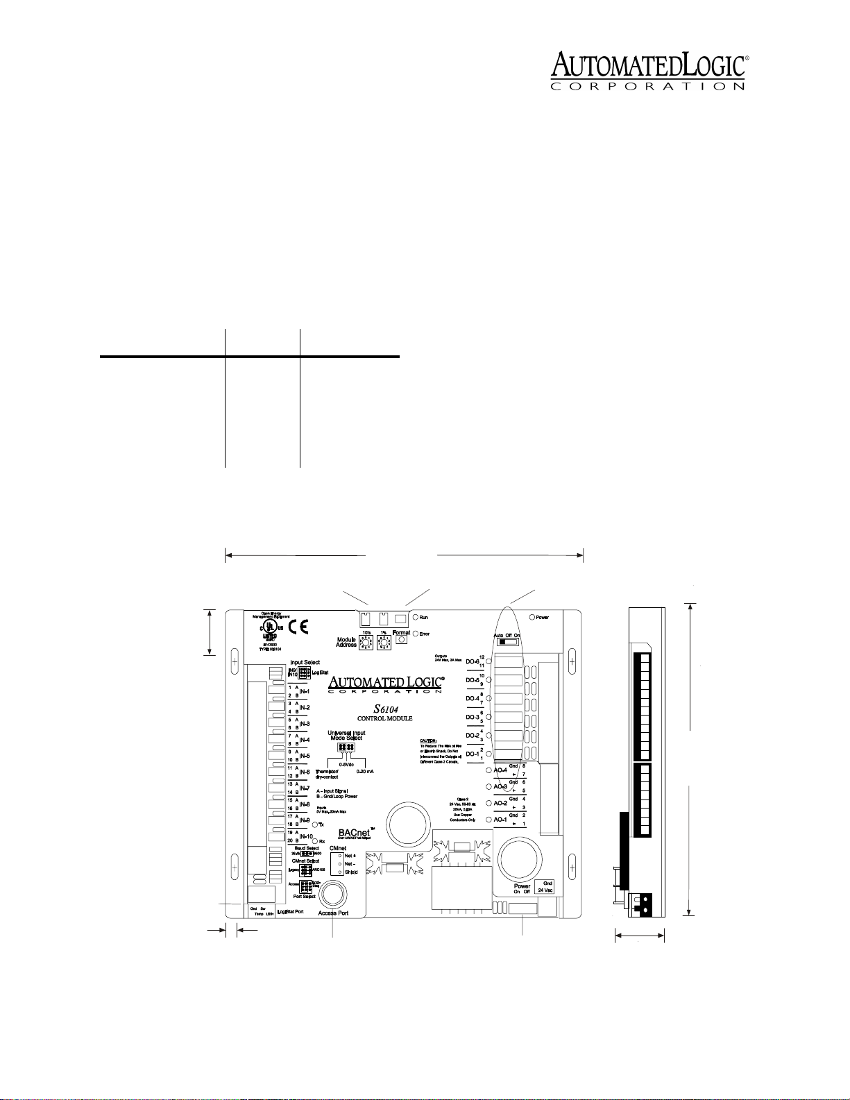
The S6104 has:
• 6 digital outputs
• 10 universal inputs
• 4 analog outputs
A single board provides the power circuitry,
microprocessor, and non-volatile memory
(stores data even during a power failure). The
Access Port allows communication with
WebCTRL or SuperVision. The 4-pin LogiStat
Port provides the interface for a LogiStat
room sensor. With certain restrictions, the
LogiStat Port can also be used to
communicate with WebCTRL or SuperVision
(see Figure 1).
11/4"
3.175 cm
LogiStat Port
Dual Rotary
Address Switches
87/8"
22.543 cm
Manua l Format
Button
Digital O utput Mode
(H O A ) S witch e s
71/2"
19 cm
1/4"
.635 cm
Revised 7/30/02 • S6104 2 © 2002 Automated Logic Corporation
Access
Port
Figure 1. S6104 Dimensions and Layout
Power
Switch
11/8"
2.858 cm
Page 3

CAUTION
unit not expressly approved by the party
responsible for compliance could void the
user’s authority to operate equipment.
NOTE
found to comply with the limits for a Class A
digital device, pursuant to Part 15 of the FCC
Rules. These limits are designed to provide
reasonable protection against harmful
interference when the equipment is operated
in a commercial environment. This
equipment generates, uses, and can radiate
radio frequency energy and, if not installed
and used in accordance with the instruction
manual, may cause harmful interference to
radio communications. Operation of this
equipment in a residential area is likely to
cause harmful interference in which case the
user will be required to correct the
interference at his own expense.
Changes or modifications to this
This equipment has been tested and
Specifications
Power
Inputs
NOTE
Input Resolution
Digital Outputs
Analog Outputs
24VAC ± 10%, 50-60Hz, 20VA
(0.83A) maximum (single Class 2 source
only, 100VA or less). (24VAC ± 10%, 60Hz
when ordered for UUKL Smoke Control
Systems.)
One LogiStat Port and 10 universal
inputs, configurable for 0-5VDC, 0-20mA,
or thermistor/dry contact.
Universal inputs 9 and 10 are
inaccessible if using a LogiStat or a
LogiStat Plus. Temperature and setpoint
adjust inputs replace universal inputs 9
and 10 in this situation.
10 bit A/D.
6 digital outputs (Form
A), 3A max.
4 analog outputs (0 to
10VDC), 20mA source capability.
For SuperVision, 156 kbps BACnet-overARCNET, 9600 bps or 38.4 kbps legacy
Control Module network (CMnet). Access
Port: 9600 bps or 38.4 kbps EIA-485.
Environmental Operating Range
to 150°F (-28.9° to 65.6°C); 10 to 90%
relative humidity, non-condensing.
When ordered for UUKL Smoke Control
Systems, 32°-120.2°F (0°-49° C); 10 to
85% relative humidity, non-condensing.
Status Indication
communication, running, errors, and all
outputs.
Memory
non-volatile battery-backed SRAM, and
128 bytes of serial EEPROM.
Real Time Clock
time clock that keeps track of time in the
event of a power failure.
Protection
protection circuitry.
Bat t e ry
provides a minimum of 10,000 hours of
data retention during power outages.
Listed by
No. 205-M1983 (PAZX7), FCC Part Subpart B - Class A.
512KB Flash memory and 512KB
Built-in surge and transient
Seven-year lithium BR2325 battery
UL 916 (PAZX), cUL C22.2
Visual (LED) status of
A battery-backed real
-20°
Mounting
Screw the S6104 into an enclosed panel using
the mounting holes provided on the cover
plate. Be sure to leave about 2 inches (5
centimeters) on each side for wiring.
Addressing
Before setting or changing the address, make
sure the S6104’s power is off. The S6104 only
reads the address when the module is turned
on. After changing the address, you must
transfer memory to the module. Refer to
“Transferring Memory” on page 14.
Output resolution
Communication
BACnet-over-ARCNET and 9600 bps or
38.4 kbps EIA-485 BACnet MS/TP.
Revised 7/30/02 • S6104 3 © 2002 Automated Logic Corporation
8 bit D/A.
For WebCTRL, 156 kbps
Page 4
The S6104 has two rotary switches for
addressing:
• For WebCTRL systems, use the switches
to assign the device’s MAC (medium
access control) address on the BACnetover-ARCNET network segment. The
rotary switches define the MAC address
portion of the device’s BACnet address
which is composed of the network
address and the MAC address.
• For SuperVision systems, use the
switches to assign the device’s module
number.
The S6104 has an operating range of 21.6VAC
to 26.4VAC. If voltage measured at the
module’s power input terminals is outside this
range, the module may not work properly.
1. Turn the module’s power off. This
prevents the module from being powered
up before the proper voltage is verified.
2. Make sure the 24VAC power source is off.
3. Connect the power wires to the module’s
power terminals labeled Gnd and 24VAC
(see Figure 1 on page 2 for location).
4. Apply power to the transformer.
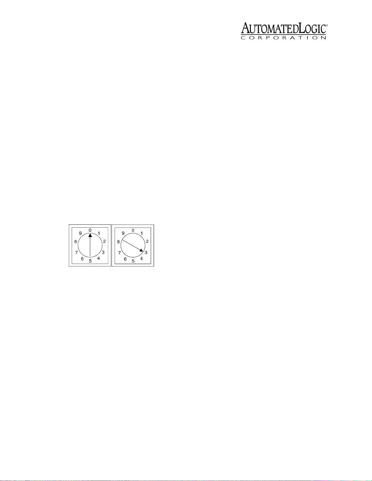
One switch corresponds to the tens digit and
the other corresponds to the ones digit. For
example, if the module’s address is three, set
the tens switch to zero and the ones switch to
three, as shown in Figure 2.
10s 1s
Figure 2. Setting the Module’s Address
Power Wiring
CAUTION
device (less than 30VAC, 100VA maximum).
Take appropriate isolation measures when
mounting the S6104 module in a control
panel where non-Class 2 devices (for
example, 120VAC) or wiring are present.
You can power several modules from the
same transformer if you maintain the same
polarity.
The S6104 module is a Class 2
5. Make sure that 24VAC is present at the
module’s power input terminals.
6. Set the module’s address. Refer to
“Addressing” on page 3 for details about
setting the address.
7. Turn the S6104’s power switch on.
When the module turns on, the Run and
Power LEDs turn on. The Run LED begins
blinking and the Error LED turns off. See
Table 9 on page 16 to troubleshoot the
LEDs. If the module does not respond, call
Technical Support at (770) 429-3002.
Network Communications
The S6104 module supports several
communications options through its CMnet
port.
On a SuperVision system, the S6104 module
can connect to a legacy CMnet at 9600 bps or
38.4 kbps, or to a BACnet-over-ARCNET
network segment at 156 kbps.
Revised 7/30/02 • S6104 4 © 2002 Automated Logic Corporation
Page 5

Using the S6104 on an ARC156 Segment
When communicating at 156 kbps, the
network segment uses a unique
implementation of the industry standard
BACnet-over-ARCNET protocol called
ARC156. For a summary of the differences
between ARCNET and ARC156, please refer to
ARC156 CMnet Wiring Technical Instructions
.
Use the appropriate wire for network
communications. When using an ARC156
network, use an A3ARC156 wire available
from:
Magnum Cable Corporation
Cleveland, OH 44110-0500
(800) 421-0820
When the CMnet Select jumper is set to
ARC156, the CMnet port is connected to an
ARCNET processor, enabling the S6104 to
communicate on an ARC156 network
segment. Communication speed is 156 kbps
regardless of the Baud Select jumper setting
(see Table 1).
Table 1. Jumper positions
CMnet
Type CMnet Select Port Select Baud Select
ARC156 ARC156 Access or
LogiStat
Legacy
CMnet Legacy Access
Not
Applicable
9600 bps or
38.4 kbps
Using the S6104 on a Legacy CMnet
Use a dedicated 22AWG to 18AWG twisted
pair wire for legacy CMnet (EIA-485) wiring.
For more information about CMnet wiring,
refer to the
When the CMnet Select jumper is set to
Legacy, the module communicates on a
legacy CMnet at the baud rate set by the Baud
Select jumper (see Table 1). The Port Select
jumper must also be set to Access.
Technical Handbook
.
NOTE
Setting the CMnet jumper to Legacy
disables the industry standard BACnet-overARCNET (ARC156) protocol for the network
segment and enables the proprietary ALC
CMnet protocol.
Connecting the S6104 to the Network
Before connecting the S6104 to the CMnet, be
sure the S6104’s power is off.
1. Set the CMnet mode (ARC156 or legacy
CMnet) using the CMnet Select jumper.
2. If communicating on a legacy CMnet, set
the Baud Select jumper for either 9600 bps
or 38.4 kbps.
NOTE
use the same baud rate.
3. Set the Port Select jumper:
• On a legacy CMnet, set the Port Select
jumper for Access.
• On an ARC156 CMnet on a WebcTRL
system, set the Port Select jumper for
LogiStat.
• On an ARC156 CMnet on a
SuperVision system, set the Port
Select jumper for either Access or
LogiStat depending on which port will
be used for serial communications
(see “Communicating with the
Workstation Using SuperVision” on
page 6).
4. Check the network communication wiring
for shorts and grounds.
5. Connect the CMnet wires to the module’s
screw terminals as shown in Figure 3 on
page 6. Be sure to follow the same
polarity as the rest of the CMnet.
All modules on the CMnet must
Revised 7/30/02 • S6104 5 © 2002 Automated Logic Corporation
Page 6

ARC156 network segment
Net
Net
Shield
To communicate through the LogiStat Port,
+
-
the S6104 must:
• be on an ARC156 CMnet
• use module driver v6.01d or later.
Communication speed is fixed at 1200 baud.
Figure 3. Wiring the CMnet
Communicating with the Wo rk s tat io n Us i n g SuperVision
The S6104 can communicate with
SuperVision through the Access Port or the
LogiStat Port. The CMnet type determines
whether the Access Port or LogiStat Port can
be used for workstation communications (see
Tabl e 2 ).
Although communication is slower through
the LogiStat Port, the LogiStat sensor may be
more accessible than the S6104 module.
NOTE
for communications when the S6104 is on an
ARC156 CMnet.
Table 2. Configuring Module/Workstation
Communications
CMnet Type
ARC156 Base and Plus
The LogiStat Port can only be used
LogiStat
Sensor Port Select Baud Rate
Base, Plus, Pro
Access
LogiStat
9600/38.4 kbps
1200 bps
CONTRO LMO DULE
LogiStat
Port
LogiStat
LogiPort
LogiStat Adaptor Cable
Exec. 4 Relay
Switch
Exec.4 relay
Isolate Network
APT
Rx
Tx +5V
Mode Select
ModeSelect
TTL
Switch
ACCESS
PORT
485
Access
Port
EIA-232
Port
5
9
6
1
2- Tx out
3- Rx in
5- Gnd
1,6,8- +10V orfloati ng
Figure 4. Using the LogiPort
1. Connect the computer’s serial port to the
EIA-232 port of the APT using a standard
straight-through cable.
Legacy Std and Plus Access 9600/38.4 kbps
2. Set the APT’s Mode Select switch to TTL
(see Figure 4.)
Communicating Through the LogiStat Port Using SuperVision
The S6104 communicates with SuperVision
through the LogiStat connected at the
module’s LogiStat Port. While connected, the
S6104 does not allow a restart, a memory
transfer, or any other action that would break
the pass-through connection.
If you are using a LogiStat Plus without
supplemental power to the APT, make
sure the LED on the LogiStat Plus is on
indicating that it can provide power to the
APT. If the LED is not on, you can provide
power to the APT using the Supplemental
Power +5V dc connection and the special
power cable to a laptop keyboard jack or
an external supply, such as a 5V dc
transformer.
Revised 7/30/02 • S6104 6 © 2002 Automated Logic Corporation
Page 7

3. Set the Port Select jumper for LogiStat to
enable communications through the
LogiStat Port.
Legacy
ARC156
Access
Logi-
Stat
Gnd Sw
LogiStat Port
Temp LS5v
Access
Port Select
LogiStat
Access Port
Figure 5. Port Select to LogiStat
4. In SuperVision, define the connection
using Table 3 on page 8.
5. In SuperVision, set the baud rate at
1200 bps.
6. Attach the LogiStat Adaptor Cable (part
number 235022) to the APT cable. Use this
assembly to connect the APT’s Access
Port to the LogiStat’s LogiPort.
While connected, the LogiStat Pro
displays “LP” indicating that the LogiStat
Pro will not respond to input from the
keypad.
NOTE
When the LogiStat Adaptor Cable
is inserted into the LogiPort, the S6104
can no longer read the LogiStat Inputs.
The S6104 will continue to use the last
valid temperature and setpoint adjust
readings obtained before the cable was
inserted into the LogiPort. If the
Occupancy Override Timer was active
when the connection was made, it will
continue to count down, but no new
inputs can be made until the LogiStat
Adaptor Cable is removed. See the
Microblock Reference Guide
for more
Eikon
information about the LogiStat
microblock.
Communicating Through the Access Port Using SuperVision
When using SuperVision, you can connect a
workstation or portable computer directly to
the S6104 module using an APT and the
module’s Access Port (see Figure 6). This type
of connection can be used to troubleshoot the
module or transfer memory. If you are using
an ARC156 CMnet, you can receive colors
while connected to a module’s Access Port if
a gateway module is on the CMnet. You
cannot receive alarms through the Access
Port, however.
CONTROLMODULE
Exec. 4 Relay
Switch
Exec. 4 re lay
Isolate Network
APT
Rx
Mode Select S witch
Tx +5V
Mode Select
TTL 485
ACCESS
PORT
EIA-232
Port
5
9
6
1
2-Tx o ut
3-R x in
5-G nd
1,6,8-+10V or floating
Figure 6. Using the Access Port
1. Connect the computer’s serial port to the
APT’s EIA-232 port using a standard
straight-through cable.
2. Set the APT’s Mode Select switch.
• On an ARC156 network segment, use
the TTL setting.
• On a legacy CMnet, use the 485 setting.
3. Connect the APT’s Access Port to the
module’s Access Port.
Access
Port
Access Port
7. Disconnect the LogiStat Adaptor Cable
from the LogiStat's LogiPort when
finished to allow the S6104 to receive
4. Set the Port Select jumper to Access to
enable communications through the
Access Port.
inputs from the LogiStat.
Revised 7/30/02 • S6104 7 © 2002 Automated Logic Corporation
Page 8

Baud Select
Baud Select
38.4K 9600
CMnet Select
Legacy
Access
Port Select
9600
ARC156
LogiStat
Access Port
Access
Port Select
38.4K
LogiStat
Gnd Sw
LogiStat Port
Temp LS 5v
Figure 7. Port Select and Baud Selects
5. Check the Baud Select jumper on the
S6104 for the communication speed of the
Access Port (9600 or 38.4K). If the jumper
needs to be changed, turn the module’s
power off first. The baud rate change
registers when the module is turned on.
6. In SuperVision, define the connection type
using Table 3.
Table 3. Connection Types
SuperVision
Ver s i o n
3.0 any n/a Access Port
2.6 ARC156 yes Direct Connect
2.6 ARC156 no Direct Network
2.6 legacy n/a Direct Network
Inputs
Type o f
CMnet
Gateway
Present?
Use Connection
Type
The S6104 provides 10 universal inputs. If you
are wiring the S6104 module to a LogiStat or
LogiStat Plus sensor, inputs 9 and 10 can be
disabled, allowing temperature and setpoint
adjust inputs to be read through the LogiStat
Port instead (see “LogiStat Wiring” on
page 10). Refer to Table 4 for information
about wire length, gauge, and shielding.
NOTE
On an ARC156 network segment,
inputs can be read through a LogiStat,
LogiStat Plus, or LogiStat Pro. However, on a
legacy CMnet, inputs can only be read on a
LogiStat or LogiStat Plus.
between 0.489V and 3.825V for
thermistors.
• 0 to 5VDC: The output impedance must
not exceed 10 kohms. The input
impedance of the S6104 is
approximately 1Mohm.
• 0 to 20mA: The input resistance on the
A input is 250 Ohms. The B terminal
supplies a voltage source to power the
4-20mA transducer. The B terminal is
capable of supplying 18 to 24VDC, but
the total current of all B terminals must
not exceed 200mA. If the voltage
measured from the B terminal to Gnd is
less than 18VDC, you need to use an
additional external power supply.
• Dry Contact: A 5VDC wetting voltage is
used to detect contact position. This
results in a 0.5mA maximum sense
current when contacts are closed.
Table 4. Input wiring restrictions
Input
0 to 5VDC 50 feet
Thermistor
Dry contact
0 to 20 mA 150 feet
LogiStat
Sensors
*Automated Logic Corporation recommends a specific
wire to connect the S6104 to the LogiStat. This 22AWG
solid copper wire is available from Magnum Cable
Corporation (part number A3LOGISTAT).
Maximum
Length
15 meters
50 feet
15 meters
46 meters
100 feet
30 meters
Minimum
Gauge Shielding
24AWG shielded and
grounded to
module’s B or
Gnd terminal
24AWG shielded and
grounded to
module’s B or
Gnd terminal
20AWG unshielded
22AWG * unshielded
• Thermistor: Precon type 2 (10 kohm at
77°F). Input voltages should range
Revised 7/30/02 • S6104 8 © 2002 Automated Logic Corporation
Page 9

Isolated DC
Powe r Supply
2Wire
4-20mA
4Wire
4-20mA
Isolated DC
Powe r Supply
Dry Contact
2Wire
4-20mA
2Wire
0-5VDC
4Wireusing
mod ule power
Input S elect
IN 9/
IN1 0
1
2
3
4
5
6
7
8
9
10
11
12
13
14
15
16
17
18
19
20
38.4k
CM net Select
To Module G round
LogiStat
A
IN -1
B
A
IN -2
B
A
IN -3
B
A
IN -4
B
A
IN -5
B
A
IN -6
B
A
IN -7
B
A
IN -8
B
A
IN -9
B
A
IN-10
B
Baud Select
9600
Universal Input
Mode S elect
0-5Vdc
Thermistor/
dry-contact
A - Input Signal
B - Gnd/Loop P ower
Inp uts
5V Max, 20mA Max
Tx
Rx
0-20 mA
Figure 8. In put Wiring
1. Be sure the S6104’s power is off before
wiring any inputs or outputs.
2. Connect the input wiring to the screw
terminals on the module as shown in
Figure 8.
NOTE
If a 4-20mA sensor uses an
external 24VAC power supply, connect
one leg of the 24VAC supply to the module
ground.
3. If using inputs 9 and 10 when wiring the
S6104 to a rooftop AHU, set the Input
Select jumper to the IN9/IN10 position.
See Figure 9. If using a LogiStat or
LogiStat Plus, see “LogiStat Wiring” on
page 10.
Open Energy
Management Equipment
R
IN9/IN10
LogiStat
88FO
E143900
TYPE: 006104
Input Select
IN9/
IN10
Figure 9. Input Select set to IN9/IN10
4. Set the Universal Input Mode Select
jumper for each input to indicate the type
of sensor used. Make sure the jumper is
positioned correctly, and be sure to grip
the jumper by the sides only. See Figure
10.
LogiStat
Revised 7/30/02 • S6104 9 © 2002 Automated Logic Corporation
Page 10

Universal Input
Mode Select
0-5VDC
Thermistor/
dry-contact
Grip
here
0-20mA
Figure 10. Universal Input Mode Select
5. Turn the S6104’s power switch on.
6. For each input, enter the point identifiers.
Refer to the section “Writing GFBs for the
S6104” on page 12 for more information
about using a LogiStat sensor.
1. Be sure the S6104’s power is off before
wiring a LogiStat to the LogiStat Port.
2. If using a LogiStat or LogiStat Plus, set the
Input Select jumper to LogiStat (see Figure
11).
NOTE
Setting the jumper to LogiStat
disables universal inputs 9 and 10.
• In WebCTRL, enter the point number
and the point type on the Properties
page. For linear inputs, set the
minimum value and maximum value to
scale the point to engineering units.
• In SuperVision, enter the channel
number, offset, and gain using the
Configure Points or Point Help feature.
Valid channel numbers are listed in
“Channel Numbers in SuperVision” on
page 13.
7. To verify each input’s operation, have
each sensor create a known value and
compare it to the condition reported on
the FB’s Properties page in WebCTRL or
Status page in SuperVision.
LogiStat Wiring
The S6104’s LogiStat Port provides the
connection for a LogiStat room sensor (see
Figure 1 on page 2). The Input Select jumper
must be set to the LogiStat position when
using a LogiStat or LogiStat Plus. This allows
the S6104 to obtain analog temperature
readings from the LogiStat through pin 2
(Temp) of the LogiStat Port. The LogiStat Plus
also provides the slidepot position and TLO
inputs through pin 3 (Sw). The LogiStat Pro
provides temperature, setpoint adjust, and
TLO inputs through serial communications.
See Table 4 for the wiring restrictions for the
S6104.
Open Energy
ManagementEquipment
R
IN9/IN10
LogiStat
88FO
E143900
TYPE : 00 6104
Input Select
IN9/
IN10
LogiStat
Figure 11. Input Select set to LogiStat
If using a LogiStat Pro, set the Input Select
jumper to IN9/IN10 to make the inputs
available for use.
3. If using a LogiStat Pro, set the Port Select
jumper to LogiStat; this enables
communications through the LogiStat
port.
NOTE
The S6104 must be on an ARC156
network segment using a LogiStat Pro.
Revised 7/30/02 • S6104 10 © 2002 Automated Logic Corporation
Page 11

4. Use Figure 12 to wire a LogiStat, LogiStat
Plus, or LogiStat Pro to the S6104.
Power
Auto Off On
1234
Gnd Sw
Temp LS5v
LogiStat Port
S6104
1234
r
d
n
x
w
x
R
P
G
T
LogiStat
Figure 12. LogiStat Wiring
Strip 1/4 inch of the ends of the wires (see
Figure 13).
2. Press black
1. Insert w ire
into opening
Figure 13. Flip Lever Wiring
tabdownto
connect wire
12
DO-6
11
10
DO-5
9
8
DO-4
7
6
DO-3
5
4
DO-2
3
2
DO-1
1
Figure 14. Digital Outputs
To verify each output’s operation, lock the
output to a known condition using the
Function Block’s Properties page in WebCTRL
or Parameter page in SuperVision. Be sure the
equipment operates as specified.
Each digital output can be placed in Manual
(on or off) or Auto mode by setting the HOA
switches (see Figure 1 on page 2 for the
switches’ location). Table 5 on page 12 shows
the status of the digital output based on the
output’s configuration and the HOA switch
position.
You can monitor the status of the HOA
switches through WebCTRL or SuperVision. In
WebCTRL, assign each switch a digital input
in the FB using the point number and the HOA
Status Feedback point type.
5. Turn the S6104’s power switch on.
In SuperVision, assign each switch a digital
input in the FB using channel numbers 81
Digital Outputs
The S6104 has 6 digital outputs which can be
connected to a maximum of 24 Volts AC/DC
(see Figure 14). Each digital output is a dry
contact (rated at 3A maximum).
Be sure the S6104’s power is off before wiring
through 86. Channel 81 corresponds to HOA
switch number one, channel 82 corresponds
to HOA switch two, and so on.
An off status means the HOA switch is in Auto
mode. An on status means the HOA switch is
in Manual mode.
any inputs or outputs. Connect the output
wiring to the screw terminals on the module.
Revised 7/30/02 • S6104 11 © 2002 Automated Logic Corporation
Page 12

Table 5. HOA Switch Positions
Output
Configuration On Off Auto
Normally open
output
Results on
Properties page
in WebCTRL* or
Status page in
SuperVision**
DO
contacts
closed
ON ON OFF
DO
contacts
open
determined
by FB
programming
module’s analog output, the total resistance
of the load must be 500 Ohms. If necessary,
wire a 1/2 watt resistor in series with the
20mA device as shown in Figure 15.
Example:
To drive a 20mA device that has
100 Ohms of resistance, wire a 400 Ohm
resistor in series with the 20mA device (100
Ohms + 400 Ohms = 500 Ohms total
resistance).
* use point type of HOA Status Feedback and point
number
** use channel numbers 81 - 86
Analog Outputs
The S6104 module has 4 analog outputs that
support voltage devices in the 0 to 10VDC
range. The device that is being controlled
must have at least 500 Ohms resistance
measured from its input to ground and must
share the same ground as the module.
AO
0-10V
100
AO
4-20mA
AO-4
AO-3
AO-2
AO-1
Gnd
+
Gnd
+
Gnd
+
Gnd
+
Power
On Off
8
7
6
5
4
3
2
1
Gnd
24 Vac
400
Be sure the S6104’s power is off before wiring
any inputs or outputs. Connect the output
wiring to the screw terminals on the module.
To verify each output’s operation, lock the
output to a known condition using the
Function Block’s Properties page in WebCTRL
or Parameter page in SuperVision. Be sure the
equipment operates as specified.
Writing GFBs for the S6104
You must use Eikon v3.0a or later to create
GFBs for the S6104. When using a LogiStat
sensor with the S6104, include a LogiStat
microblock in the module’s GFB (see Figure
16). The LogiStat microblock supports the
LogiStat, LogiStat Plus, and LogiStat Pro
sensors. You do not need to enter point
numbers or point types in SuperVision or
Eikon for WebCTRL. Likewise, you do not
need to enter channel numbers for this
microblock in SuperVision or Eikon. For more
information, refer to the
Reference Guide
.
Eikon Microblock
Figure 15. Analog Output Wiring
Although the S6104’s analog outputs were
not designed to output current, it is possible
to use these outputs for current mode
devices. To drive a 20mA device from the
Revised 7/30/02 • S6104 12 © 2002 Automated Logic Corporation
Page 13

Figure 16. Sample GFB for the S6104
Point Identifiers
A point can be identified in WebCTRL by its
point number and point type; in SuperVision,
a point is identified by its channel number. On
both systems, expander number zero
represents I/O points on the S6104.
Point Identifiers in WebCTRL
Enter the point identifiers in Eikon for
WebCTRL before the FB is made or on the FB’s
Properties page in WebCTRL. Set the type,
number, and minimum and maximum
present values for each point on the S6104.
Select a physical point type from the point
type field and enter the number of the input or
output. To scale a linear signal type, enter the
appropriate minimum and maximum present
values on the microblock’s dialog box.
Channel Numbers in SuperVision
The following tables show the valid channel
numbers for each point on the S6104. The
offset and gain values used depend on the
type of sensor or actuator attached to the I/O
point. You can select the channel number,
offset, and gain using SuperVision’s Point
Help feature or Configure Points utility.
Alternatively, you can preconfigure the points
by manually entering the channel number,
offset, and gain in Eikon using the values
shown in the following tables.
Table 6. Analog Output Channel Numbers
Point Signal Type
AO 1 Analog 41 0 to 10VDC 0.00 0.0625
AO 2 Analog 42 0 to 10VDC 0.00 0.0625
AO 3 Analog 43 0 to 10VDC 0.00 0.0625
AO 4 Analog 44 0 to 10VDC 0.00 0.0625
Channel
Number Range Offset Gain
Table 7. Digital Output Channel Numbers
Point Signal T ype
DO 1
DO 2
DO 3
DO 4
DO 5
DO 6
Digital
HOA Status
Digital
HOA Status
Digital
HOA Status
Digital
HOA Status
Digital
HOA Status
Digital
HOA Status
Channel
Number
11
81
12
82
13
83
14
84
15
85
16
86
Table 8. Universal Input Channel Numbers
Point Signal T ype
Thermistor 31
UI 1
mA or Volts 31
Digital 21
Channel
Number †Range Offset Gain
-17° to 213° F
-27° to 100.6° C
0 to 20mA
0 to 5V
0.00
15.88
0.00
15.69
§§
Revised 7/30/02 • S6104 13 © 2002 Automated Logic Corporation
Page 14

Table 8. Universal Input Channel Numbers
Point Signal Type
Thermistor 32
UI 2
UI 3
UI 4
UI 5
UI 6
UI 7
UI 8
UI 9 *
UI 10 *
* This input is not available when using a LogiStat or LogiStat Plus.
† Celsius values can only be displayed in SuperVision when the Function
Block is made in Eikon v2.0 or later with the Metric option enabled. Refer to
the Eikon User’s Guide for more information.
§ For ALC 0-20mA sensors, use the offset and gain printed on the sensor.
Otherwise use the Point Configuration or Point Help feature in SuperVision
v2.0 or later.
mA or Volts 32
Digital 22
Thermistor 33
mA or Volts 33
Digital 23
Thermistor 34
mA or Volts 34
Digital 24
Thermistor 35
mA or Volts 35
Digital 25
Thermistor 36
mA or Volts 36
Digital 26
Thermistor 37
mA or Volts 37
Digital 27
Thermistor 38
mA or Volts 38
Digital 28
Thermistor 39
mA or Volts 39
Digital 29
Thermistor 3A
mA or Volts 3A
Digital 2A
Channel
Number †Range Offset Gain
-17° to 213° F
-27° to 100.6° C
0 to 20mA
0 to 5V
-17° to 213° F
-27° to 100.6° C
0 to 20mA
0 to 5V
-17° to 213° F
-27° to 100.6° C
0 to 20mA
0 to 5V
-17° to 213° F
-27° to 100.6° C
0 to 20mA
0 to 5V
-17° to 213° F
-27° to 100.6° C
0 to 20mA
0 to 5V
-17° to 213° F
-27° to 100.6° C
0 to 20mA
0 to 5V
-17° to 213° F
-27° to 100.6° C
0 to 20mA
0 to 5V
-17° to 213° F
-27° to 100.6° C
0 to 20mA
0 to 5V
-17° to 213° F
-27° to 100.6° C
0 to 20mA
0 to 5V
0.00
15.88
0.00
15.69
§§
0.00
15.88
0.00
15.69
§§
0.00
15.88
0.00
15.69
§§
0.00
15.88
0.00
15.69
§§
0.00
15.88
0.00
15.69
§§
0.00
15.88
0.00
15.69
§§
0.00
15.88
0.00
15.69
§§
0.00
15.88
0.00
15.69
§§
15.88
0.00
15.69
Transferring Memory
You should download memory whenever you
make changes to your modules (for example,
change the module number, upgrade the
module driver, or change the FB).
The S6104 can store a single Function Block
in addition to the module driver. If any
problems occur during this procedure,
contact Technical Support at (770) 429-3002.
NOTE
performed with caution. When the module is
automatically restarted before and after
transferring memory, any equipment
controlled by the module is shut down and
restarted. Downloading memory also
overwrites all Function Blocks in the module
causing the module to lose any stored data.
Transferring Memory in WebCTRL
If you are using WebCTRL to transfer memory,
you must use the DRV_S6104 module driver.
You must be logged in to WebCTRL with the
appropriate privilege to download memory.
For more information about using WebCTRL,
refer to the
1. Click the CFG button at the bottom of the
2. Click Download in the CFG tree control.
3. Click the Memory, Parameters, or
4. Expand the tree in the action pane, click
5. Click the Execute Download button.
A memory download should be
WebCTRL Configuration Guide
.
navigation pane.
Schedules boxes, depending on what you
want to download.
NOTE
A memory download includes a
parameter and schedule download.
the module you want to download to,
then click Add. Click on and Add any
other modules you want to download to.
If any downloads failed, they are listed in
the Failures section under the tree in the
Revised 7/30/02 • S6104 14 © 2002 Automated Logic Corporation
Page 15

action pane. To retry a failed download,
click the module in the Failures list, click
Add, and click the Execute Download
button again. If you do not want to retry a
failed download, click the Clear Failures
button.
NOTE
a system problem, you should never clear
a failure. Locate and resolve the problem,
then retry the download.
6. Click the Properties button to refresh the
screen. This removes the items from the
Download Items list.
Since a failed download indicates
Transferring Memory in SuperVision
If you are using SuperVision to transfer
memory, you must use SuperVision v2.6b or
later, FB Link v2.7a or later, and the SLM
module driver. The S6104 module using the
SLM module driver can store a single FB.
1. Log in to SuperVision on a workstation
connected to the CMnet. You can also
connect directly to the module using the
Access Port or LogiStat Port; see
“Communicating with the Workstation
Using SuperVision” on page 6.
2. Navigate to the module driver and look at
the module status report in SuperVision to
make sure the module type and number
agree with the module.
• To view the module status report in
SuperVision v3.0, click Tools Troubleshooting - Module Status.
• In SuperVision v2.6b, download
memory for This Module.
4. When the memory transfer is finished,
check the module status report again.
Make sure the FB List on this page shows
the FB you intended to transfer.
Troubleshooting
Formatting the Module
If you are unable to communicate with a
module after transferring memory, you can,
as a last resort, manually format the module
to try to restore communication. Formatting
the module erases all memory, so you need to
transfer memory back to the module once it is
formatted.
NOTE
formatted when you transfer memory, you
should only manually format the module if
communication was not established after the
memory transfer.
1. Turn the module’s power off. Make sure
2. Press and hold the Format button (see
3. Continue to hold the button until the Error
4. Release the Format button.
Since the module is automatically
the address switches are not set to ‘0 0’.
Figure 1 on page 2 for location). While
continuing to hold the Format button, turn
the module’s power on.
LED flashes three times in sync with the
Run LED.
• To view the module status report in
SuperVision v2.6b or later, press the
[ESC} key, type
MO ,,module address,15
and press Enter.
3. Transfer memory to the module.
• In SuperVision v3.0, click Tools Troubleshooting - Transfer Memory to
Module.
Revised 7/30/02 • S6104 15 © 2002 Automated Logic Corporation
5. Transfer memory to the module. Refer to
“Transferring Memory” on page 14.
LEDs
The S6104 module has several LED indicators
to show the status of certain functions.
Table 9 on page 16 explains the Run and Error
LED signals in detail to assist troubleshooting.
See Figure 17 for location of LED signals.
Page 16

Run Error
Power
Table 9. LED Signals (Continued)
Run LED Error LED Condition
Digital Output
Status
Analog Output
Status
CMnet
Tx
CMnet
Rx
S6104
Control Module
L
A
CO RPORATIO N
UTOMATED
OGIC
12
11
Figure 17. S6104 LED locations
Power - indicates power is being supplied to
the module.
CMnet Tx - lights when the module transmits
data over the CMnet.
CMnet Rx - lights when the module receives
data from the CMnet.
Digital Output Status - lights when the digital
output is activated.
Analog Output Status - lights when the
analog output is activated.
Table 9. LED Signals
Run LED Error LED Condition
2 flashes
per second
2 flashes
per second
2 flashes
per second
2 flashes
per second
2 flashes
per second
Off Normal
1 flash,
then pause
2 flashes
alternating
with LED
2 flashes in
sync with
LED, then
pause
3 flashes,
then off
Normal, but module is
alone on the CMnet
(this sequence doesn’t
occur in WebCTRL)
Five minute auto-restart
delay after system error
Module is configured for a
different baud rate than the
rest of the network
segment
Module has just been
formatted
2 flashes
per second
2 flashes
per second
5 flashes
per second
5 flashes
per second
7 flashes
per second
14 flashes
per second
4 flashes,
then pause
On Exec halted after frequent
On Exec start-up aborted, Boot
Off Firmware transfer in
7 flashes
per second,
alternating
with LED
14 flashes
per second,
alternating
with LED
Two or more devices on
this network have the
same ARC156 network
address
system errors or GFBs
halted
is running
progress, Boot is running
Ten second recovery
period after brownout
Brownout
Protection
The S6104 module is protected by internal
solid state Polyswitches on the incoming
power and network connections. These
Polyswitches are not replaceable and will
reset themselves if the condition that caused
the fault returns to normal.
Production Date
To determine when a module was
manufactured, check the module status
report for the module in WebCTRL or
SuperVision. Refer to the appropriate user’s
guide for more information about the module
status report.
A sticker on the back of the module also
shows the date the module was
manufactured. The first three characters on
the sticker indicate the type of module. The
next two characters show the year and month
(the month digit is in hexadecimal).
Revised 7/30/02 • S6104 16 © 2002 Automated Logic Corporation
 Loading...