

Page 1
17514_ins_alc_lsp2h_lsb2h
(0 to 5 VDC - 0 to 100% RH)
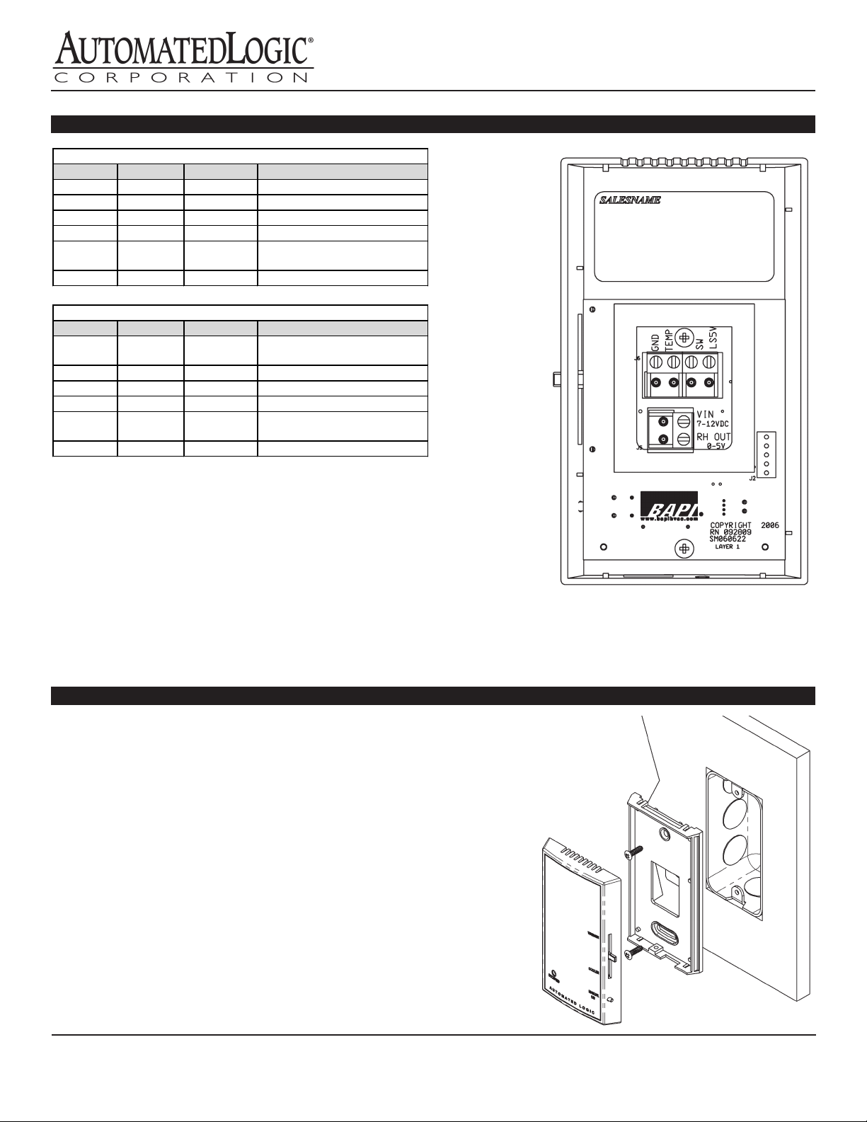
LSBASE2H Terminal Connections
LED, RH)
TEMP Tx Green Room Temperature (sensor)
SW Rx Yellow Setpoint Adjust and TLO
LS5V PWR Red LED
RH OUT
Relative Humidity
VIN 7 to 12VDC for Humidity
LSPLUS2H Terminal Connections
Termination
Terminal Alt. Name Lead Color Function
GND GND Black Ground (sensor, RH)
TEMP Tx Green Room Temperature (sensor)
SW Rx Yellow Not Used
LS5V PWR Red Not Used
RH OUT Relative Humidity
VIN 7 to 12 VDC for Humidity
Terminal Alt. Name Lead Color Function
GND GND Black Ground (sensor, setpoint, TLO,
(0 to 5 VDC - 0 to 100% RH)
LSPLUS2H and LSBASE2H
Installation & Operations
rev. 10/15/12
The relative humidity signal (“RH OUT” terminal) should be taken to an
unused analog input on the controller.
When used with an ALC module equipped with RNet, the RNet 12 VDC
supply may be used to power the unit. If there is not a convenient source of
7 to 12 VDC power, an ALC/VC350A or ALC/VC350A-EZ may be used.
Note: The connectors use a rising block screw terminal to hold the wires.
If the block is in a partially up position, the wire may be inserted under the
block and the wire will not be held when the screw is tightened. To avoid
improper wiring, turn the male connector screws counterclockwise until the
block is below the wire opening before inserting the wire. Lightly tug on
each wire after tightening to verify proper termination.
Mounting
1. Secure the base to the junction box using the #6-32 x 1/2” mounting
screws provided.
2. For drywall installation, pre-drill two 3/16” holes 3.275” apart on
center. Insert the drywall anchors and secure the base using the #6 x
1” sheet metal screws provided.
3. Terminate the unit as shown in the Terminations section.
4. Attach the cover by latching it to the top of the base.
5. Rotate the cover down.
Automated Logic Corporation
1150 Roberts Boulevard
Kennesaw, GA 30144
Phone: (770) 429-3000
Fax: (770) 429-3001
www.automatedlogic.com
Page 2
17514_ins_alc_lsp2h_lsb2h
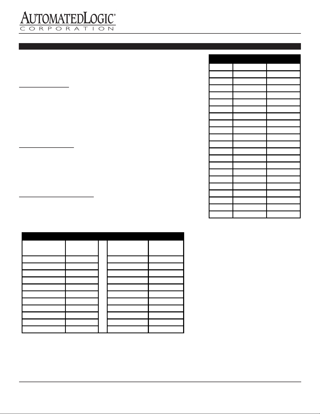
Deg F Deg C 10K-2 Ω
55°F 12.8°C 17,439
62°F 16.7°C 14,546
66°F 18.9°C 13,139
72°F 22.2°C 11,307
80°F 26.7°C 9,298
84°F 28.9°C 8,448
88°F 31.1°C 7,685
90°F 32.2°C 7,333
100°F 37.8°C 5,826
0% 0 55% 2.750 VDC
10% 0.500 VDC 65% 3.250 VDC
25% 1.250 VDC 80% 4.000 VDC
50% 2.500 VDC
Diagnostics
LSPLUS2H and LSBASE2H
Installation & Operations
rev. 10/15/12
If the unit does not respond properly, please go through the following steps:
1. Set a meter to the “Ohms” setting
2. Disconnect the TEMP, SW and RH OUT terminals from the system
Temperature Sensor
3. Measure the resistance from terminal GND to TEMP
4. Compare the resistance reading to the resistance listed in the output table.
5. If the sensor reads signicantly lower or 0 Ohms, then the sensor is shorted
6. If the sensor reads signicantly higher or OL (overload) then the sensor is
open.
7. If the sensor reads properly, verify that the controller is operating correctly.
Setpoint and Override
8. Measure the resistance from terminal GND to SW.
9. The resistance should range from 4.75 kΩ to 24.75 kΩ (±10%) as the slide
pot is moved from left to right.
10. Pushing the override switch should cause the resistance reading to go to
approximately 0Ω.
Relative Humidity Diagnostics
11. Measure the voltage from terminal GND to RH OUT.
12. The relative humidity is found by solving the following equation:
%RH = RH OUT * 20
Relative Humidity Output Table
Relative
Humidity
Output
Voltage
Relative
Humidity
Output
Voltage
10K-2 Thermistor Output Table
50°F 10.0°C 19,903
60°F 15.6°C 15,313
64°F 17.8°C 13,822
68°F 20.0°C 12,493
70°F 21.1°C 11,884
74°F 23.3°C 10,762
76°F 24.4°C 10,247
77°F 25.0°C 10,000
78°F 25.6°C 9,760
82°F 27.8°C 8,862
86°F 30.0°C 8,056
95°F 35.0°C 6,530
Note: The temperature table shown
above is a portion of the entire
operating range of the sensor.
5% 0.250 VDC 60% 3.000 VDC
15% 0.750 VDC 70% 3.500 VDC
20% 1.000 VDC 75% 3.750 VDC
30% 1.500 VDC 85% 4.250 VDC
35% 1.750 VDC 90% 4.500 VDC
40% 2.000 VDC 95% 4.750 VDC
45% 2.250 VDC 100% 5.000 VDC
Automated Logic Corporation
1150 Roberts Boulevard
Kennesaw, GA 30144
Phone: (770) 429-3000
Fax: (770) 429-3001
www.automatedlogic.com
 Loading...