

Page 1

Technical Instructions
LGRM-E
Using the LGRM-E 2
Specifications 3
Mounting 3
Addressing 3
LGnet addressing 3
IP Addressing 4
Wiring 5
Power Wiring 5
Communications Wiring 5
Initializing the LGRM-E 6
Transferring Memory 7
Troubleshooting 7
Communicating with the Workstation 7
Formatting the Module 9
LEDs 9
Protection 10
Production Date 10
Automated Logic Corporation • 1150 Roberts Blvd. • Kennesaw, GA 30144 • 770/429-3000 • 770/429-3001 Fax •
www.automatedlogic.com • Copyright 2002 Automated Logic Corporation. All rights reserved. Automated Logic, the
Automated Logic logo, SuperVision, Eikon, and Alert are registered trademarks of Automated Logic Corporation.
InterOp is a trademark of Automated Logic Corporation. BACnet
and product names are trademarked by their respective companies.
®
is a registered trademark of ASHRAE. All other brand
Page 2
Using the LGRM-E
The LGRM-E is part of the Gateway family and
provides communication between a
workstation and a control module network
(CMnet) consisting of fewer than 100
modules. Up to 199 gateways can be
networked together on an LGnet, allowing
the LGRM-Es to route global information
between CMnets. While the LGRM-E supports
199 gateways, versions of SuperVision earlier
than 3.01 do not support more than 60
gateways.
The LGRM-E provides an Ethernet 10base-T
port for 10Mbps communication with the
LGnet. Two console ports that can be
connected to a workstation, portable
computer, or modem, an Auxiliary Device
Port (Keypad/Display Port), and an Access
Port are also provided.
Console Port 1 is a 9-pin EIA-232 connector.
Console Port 2 is a 5-pin terminal jumper.
TCP/IP (Transmission Control Protocol/
Internet Protocol) is a family of protocols used
for computer communications. The LGRM-E
uses the UDP/IP (User Datagram Protocol/
Internet Protocol) of the TCP/IP family. The
workstation must be configured to
communicate with the LGRM-E over TCP/IP
as discussed in the document
Windows 95/NT and SVW 2.6
TCP/IP Setup for
(Part number
LGTCPIP).
The LGRM-E must use v6.00g or later of the
LEM module driver; for more information, see
LEM Module Driver
the
document on the
Automated Logic website at
www.automatedlogic.com
or on the SupportPlus CD.
NOTE
This equipment has been tested and
found to comply with the limits for a Class A
digital device, pursuant to Part 15 of the FCC
Rules. These limits are designed to provide
reasonable protection against harmful
interference when the equipment is operated
in a commercial environment. This
equipment generates, uses, and can radiate
radio frequency energy and, if not installed
and used in accordance with the instruction
manual, may cause harmful interference to
radio communications. Operation of this
equipment in a residential area is likely to
cause harmful interference in which case the
user will be required to correct the
interference at his own expense.
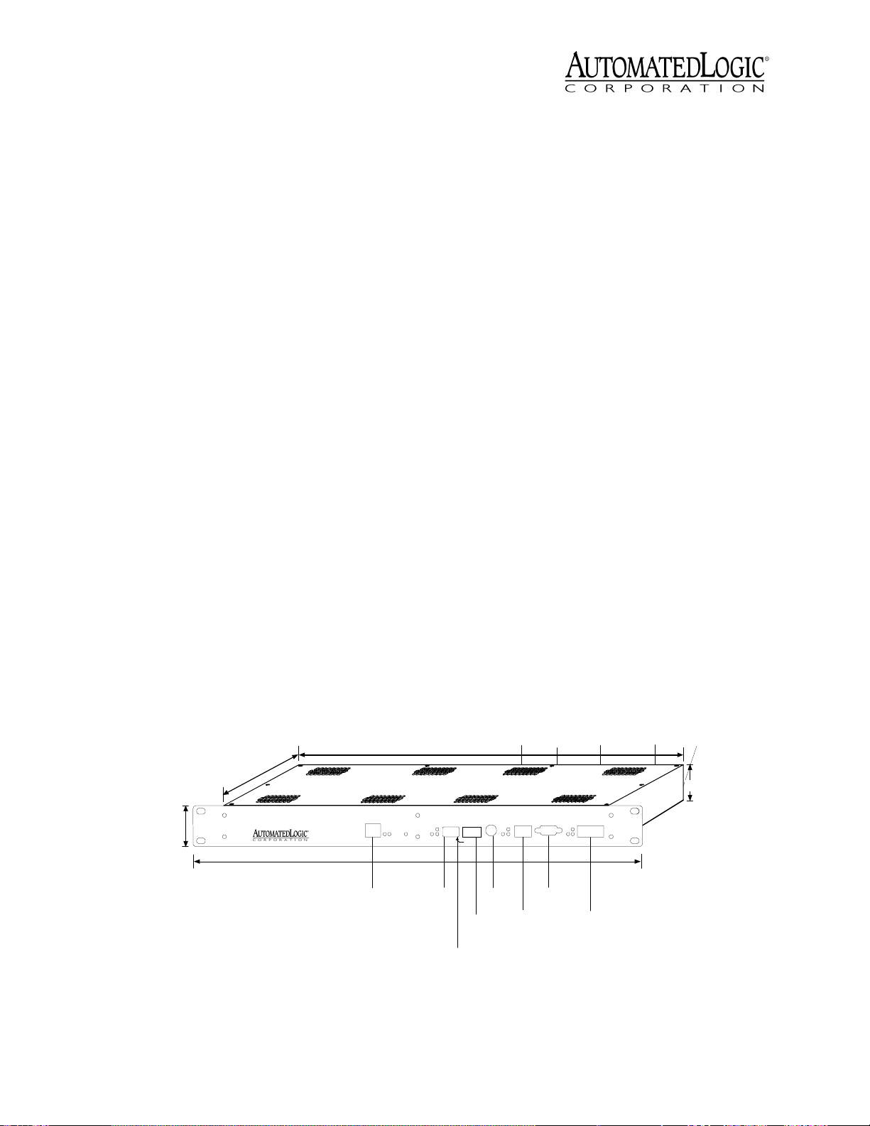
13/4"
4.45cm
10 3/16"
25.88cm
LGRM-E
RJ45
10base
T
Ethernet
10baseT
Port
K
N
I
L
N
A
L
t
e
r
n
r
e
e
w
h
o
t
P
E
19 1/16"
48.42cm
17"
43.18cm
e
l
r
u
e
Error
d
w
o
o
P
M
Run
DIP
Switches
Addressing
e
c
n
a
g
g
i
s
e
s
k
k
k
L
4
4
4
/
A
.
.
.
/
6
t
8
8
8
l
5
3
3
3
u
1
/
/
/
d
d
d
a
0
0
0
C
f
u
u
u
0
0
0
R
e
a
a
a
6
6
6
A
b
9
b
9
b
9
d
D
r
1
2
d
d
n
n
a
o
d
o
o
g
A
M
C
y
C
e
P
c
L
I
DIP
Switch
s
'
0
0
10's 1's
y
1
LGnet
e
Address
Access
Addressing
Rotary
Switches
Com
Sta
m
t
Access
CMn
Por
et
t
Port
Connecti on
Auxiliary
Power
-
t
t
e
e
N
N
+
Rx
Tx
CMn
Connec-
et
tion
CMnet
Auxiliary
Device
Console
d
l
e
i
Connec-
1
h
S
tion
x
D
R
C
2
1
D
C
/
N
Console
Port 1
Format
Button
Port
D
R
C
T
x
x
D
R
T
D
D
R
T
N
x
T
D
G
3
4
5
Rx
Com
Sta
m
t
7
Tx
V
C
C
/
/
0
Console 2
1
6
9
N
8
N
Console
+
Connec-
2
tion
Console
Port 2
Power
Connector
l
n
a
u
n
o
r
g
i
d
G
S
Power
Switch
125/32"
4.5cm
Figure 1. Module dimensions and layout
Revised 11/6/02 • LGRM-E 2 © 2002 Automated Logic Corporation
Page 3
Specifications
Addressing
Power
115VAC ±10%, 15W, 60Hz wall
outlet adapter.
Adapter Output
9VDC, 0.75A minimum,
supplied.
Auxiliary Device Power
24VAC ±10%,
0.5A, 12VA, 60/50Hz.
Communications
LGnet Port with Ethernet
10base-T (10Mbps). CMnet Connection
with EIA-485, twisted pair, selectable for
156 kbps, 38.4 kbps, or 9600 bps. One
9-pin EIA-232 connector Console Port for
direct connect or modem. One 5-pin
connector Console Port for direct connect
or modem. One Access Port for direct
network using an APT. One Auxiliary
Device Port (Keypad/Display Port).
Environmental Operating Range
130°F (-17.8 to 54.4°C); 10 to 90% relative
humidity, non-condensing.
Status Indication
Visual (LED) status of
CMnet, Console Ports and Ethernet
communications, errors, running, and
power.
Memory
256KB Flash, 512KB
battery-backed static RAM.
0 to
LGnet addressing
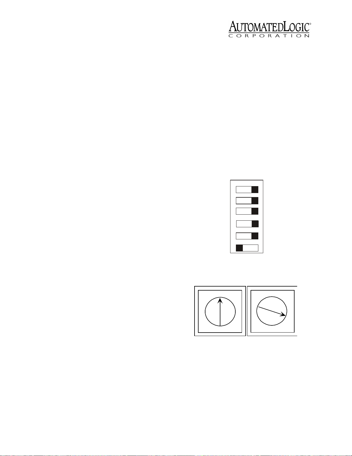
The LGRM-E has two rotary switches and a
DIP switch used to assign the LGRM-E’s
address. One rotary switch corresponds to the
tens digit and the other corresponds to the
ones digit. DIP switch six corresponds to the
100s digit.
NOTE
may not recognize an LGRM-E if the its
address is higher than 60. However, LGRM-Es
recognize peer gateways with addresses from
1 to 199.
SuperVision v2.6 and some gateways
Switch
Number
CMnet
1
Con 1
2
Con 2
3
IP ADD
4
Mode
5
9600/38.4k baud
9600/38.4k baud
9600/38.4k baud
Default/Assigned
Legacy/ARC156
Protection
Built-in surge and transient
protection circuitry.
Listed By
UL 916 (PAZX), cUL C22.2
No.205 - M1983 (PAZX7).
Mounting
The LGRM-E is rack-mounted using four
holes on the faceplate (see Figure 1 on page
2). If a rack is not available, the LGRM-E can
be mounted with mounting brackets.
The LGRM-E is designed to be mounted inside
the building. All warranties are void if
mounted outside.
CAUTION
unit not expressly approved by the party
responsible for compliance could void the
user’s authority to operate equipment.
Changes or modifications to this
6
0
Figure 2. DIP Switches
100s
10's 1's
0
9
8
7
6
Figure 3. rotary Switches
1
2
3
4
5
0
9
8
7
6
1
2
3
4
5
For example, if the LGRM-E’s address is 3, set
DIP switch six to zero (see Figure 2), the tens
rotary switch to zero, and the ones rotary
switch to three (see Figure 3).
Revised 11/6/02 • LGRM-E 3 © 2002 Automated Logic Corporation
Page 4

Before setting or changing the address, make
sure the LGRM-E’s power is off. The LGRM-E
only reads the address when the module is
turned on. After changing the address, you
must transfer memory to the module. Refer to
“Transferring Memory” on page 7.
Default mode
Use the following procedure to set the IP
address when using the Default mode:
1. Set the IP ADD DIP switch to Default.
2. Turn the LGRM-E’s power on.
IP Addressing
TCP/IP must be set up on the workstation
with an active IP address before configuring
the module’s IP address (refer to the
Setup for SuperVision Workstations Technical
Instructions
for a detailed procedure).
You can use a default IP address for the
LGRM-E that is created by the module, or
assign an IP address if required by the
customer. The IP ADD switch (Figure 2 on
page 3) determines which IP address is used.
• Default: When the IP ADD switch is set
to Default, the following IP networking
parameters are automatically set on the
LEM Parameter page:
IP Address = 192.168.168.XXX
XXX is the LGRM-E’s LGnet address (see
“LGnet addressing” on page 3).
TCP/IP
, where
3. If using SuperVision v2.6, edit your HOSTS
file to include the following line for each
gateway (see the
TCP/IP Setup for
SuperVision Workstations Technical
Instructions
for a detailed procedure):
192.168.168.x
Where x is the gateway’s address as
defined in “LGnet addressing” on page 3.
4. If using SuperVision v2.6, run Setup.exe
on the disk shipped with your LGRM-E.
This setup copies updated Portman files to
your emsys folder.
5. Configure the connection as Network in
SuperVision Plus v3.01 and later or
NetBIOS in SuperVision v2.6.
Assigned mode
Use the following procedure to set the IP
address when using the Assigned mode:
Subnet Mask = 255.255.255.0
Default Gateway Address =
19 2 . 168.168.254
NOTE
The default gateway address is
an intranet address. This means that the
data packets from this address are
dropped by all internet routers and are
not sent beyond the local network
segment.
• Assigned: When the IP ADD DIP switch
is set to Assigned, you must set the
above parameters on the LEM
Parameter page.
1. Obtain an IP address from the job site’s
Network Administrator.
2. Set the IP ADD DIP switch to Assigned.
3. If using SuperVision v2.6, edit your HOSTS
file to include the following line for each
gateway (see
Workstations Technical Instructions
TCP/IP Setup for SuperVision
for a
detailed procedure):
IP Address LGx
Where IP Address is the address assigned
by the Network Administrator and x is the
gateway’s LGnet address.
4. If using SuperVision v2.6, run Setup.exe
on the disk shipped with your LGRM-E.
Revised 11/6/02 • LGRM-E 4 © 2002 Automated Logic Corporation
Page 5

This setup copies updated Portman files
files to your emsys folder.
Use the following procedure to connect
power to the LGRM-E.
NOTE
If SuperVision is running, exit and
restart SuperVision before performing step 5.
5. Establish communication with the
LGRM-E through SuperVision using one of
the connection types in Table 1.
Table 1. Connecting with the Workstation
Port Cable
Access Port APT Access Port Direct
Console
Ports
DC95, DC99,
or APT
SuperVision
v3.01
Direct
Connect
SuperVision
v2.6
Network
Direct
Connect
6. Enter the following information, provided
by the Network Administrator, on the LEM
Parameter page and transfer parameters:
• the Assigned IP address
• the Assigned Subnet Mask
1. Turn off the LGRM-E’s power switch.
2. Connect the terminal strip connector (see
Figure 4) to the power connector on the
back of the LGRM-E (see Figure 5 on page
6).
3. Plug the power adaptor into an outlet.
4. Turn the module’s power switch on.
When the module turns on, the Run and
Power LEDs turn on. The Run LED begins
blinking and the Error LED turns off. See
Table 3 on page 10 to troubleshoot the
LEDs. If the module does not respond,
call Technical Support at (770) 429-3002.
To use the Auxiliary Device Port (Keypad/
Display Port), plug the ALC #240034 wall
transformer into an outlet and attach the
other end to the auxiliary power connector.
• the Default Gateway Address
7. Configure your connections page for
Network in SuperVision Plus v3.01 and
later, or NetBIOS in SuperVision v2.6.
Wiring
Power Wiring
Whenever possible, make sure the module’s
power and communications connections are
working properly before connecting any input
or output points.
CAUTION
device (less than 30VAC, 100VA maximum).
Take appropriate isolation measures when
mounting the LGRM-E module in a control
panel where non-Class 2 devices (for
example, 120VAC) or wiring are present.
You can power several modules from the
same transformer if you maintain the same
polarity.
The LGRM-E module is a Class 2
Terminal Strip
Connnector
120 VAC
50-60Hz
(230V, 50Hz)
Figure 4. AC Power Ad apter
Output: 9VDC
.75 Amps
minimum
Communications Wiring
When communicating at 156 kbps, the CMnet
uses a unique implementation of the industry
standard ARCNET protocol called ARC156.
For a summary of the differences between
ARCNET and ARC156, please refer to the
ARC156 CMnet Wiring Technical Instructions
Use the appropriate wire for CMnet
communications. When communicating with
the ARC156 protocol, use an A3ARC156 wire
available from:
.
Revised 11/6/02 • LGRM-E 5 © 2002 Automated Logic Corporation
Page 6

Power
Switch
Off On
Power
Connector
+9 Vdc Gnd
700mA Min
Source Only
Format
Auxiliary
Device
Port
Auxiliary
Power
24 Vac Gnd
Single Class 2Singl e Cl ass 2
Source Only
Power
Switch
Power
Connector
Format
Button
Figure 5. Bac k View of L GRM-E
Magnum Cable Corporation
Cleveland, OH 44110-0500
(800) 421-0820
Use a dedicated 22AWG to 18 AWG twisted
pair (EIA-485) for legacy CMnet. For more
information about CMnet, refer to the
Technical Handbook
Wiring Technical Instructions
ARC156 CMnet
or to
.
Configure the communication speeds using
the DIP switches (see Figure 1 on page 2 for
location). Each switch functions as follows:
Auxiliary
Power
Auxiliary
Device
Port
(Keypad/Display Port)
Connector
Be sure to follow the same polarity as
used throughout the rest of the CMnet.
3. Make sure the LGRM-E is configured for
the correct communication speed.
Connecting to the LGnet
Connect a LAN 10base-T cable to the
Ethernet port.
Connecting to a Workstation or Modem
Connect the DC95 or DC99 cable to console
port 1 or 2. See “Communicating with the
Workstation” on page 7 for more details.
CMnet
Sets the CMnet baud rate at 9600/
38.4 baud.
Con 1
Sets Console Port 1’s baud rate at
9600 or 38.4 baud.
Con 2
Sets Console Port 2’s baud rate at
9600 or 38.4 baud.
IP Add
Sets the addressing mode to either
Default or Assigned on the 10base-T
Ethernet connection (see “IP Addressing”
on page 4 for more information).
Mode
Sets the CMnet to either ARCNET (156
kbps) or Legacy (9600/38.4 baud).
1. Turn off the power.
2. Attach the two CMnet communications
wires to the CMnet connection labeled
Net - and Net + on the LGRM-E (see Figure
1 on page 2). Also connect the Shield if on
an ARC156 CMnet.
NOTE
The EIA-232 connection should not
exceed 50 ft (15.24 m) in length without an
Opto Repeater. Refer to the
Technical Instruction
for further information.
Opto Repeater
Initializing the LGRM-E
Before the LGRM-E can communicate with
the CMnet or the workstation, you must
initialize it with the following information:
• The maxnet value, which is the total
number of modules on the CMnet
(including the LGRM-E) plus one. The
LGRM-E uses maxnet to determine
when to begin the token passing cycle
on the CMnet.
• If the workstation is connected to the
LGRM-E by modem, the workstation
Revised 11/6/02 • LGRM-E 6 © 2002 Automated Logic Corporation
Page 7

telephone number from the SuperVision
connections page.
• The system’s line number.
• The three-letter system name.
Initialize the gateway module when:
• The LGRM-E is replaced or reformatted.
• A new module is added to the CMnet.
• The workstation phone number is
changed in SuperVision.
• The three-letter system name is
changed.
• The LGRM-E’s LGnet address is
changed.
To initialize the LGRM-E using SuperVision
v2.6 or earlier, issue the SETGCM manual
command. In SuperVision 3.0, navigate to the
LGRM-E’s module driver parameter page,
then choose the Tools - Troubleshooting Initialize Gateway command.
Transferring Memory
The LGRM-E uses the LEM module driver. No
other FBs can be added to the LGRM-E. If any
problems occur during this procedure,
contact Technical Support at (770) 429-3002.
If you are transferring memory that includes
changing the module driver or its version
number, the transfer takes longer than
subsequent transfers.
1. Connect your workstation or portable
computer to the LGRM-E. Refer to
“Communicating with the Workstation” .
• To view the module status report in
SuperVision v2.6b, press the Esc key,
MO , , module address,15
type
and press Enter.
3. Transfer memory to the module.
• In SuperVision v3.0, click
Tools-Troubleshooting-Transfer
Memory to Module.
• In SuperVision v2.6b, choose Download
Memory for This Module.
4. When the memory transfer is finished,
check the module status report again.
Make sure the FB List on this page shows
all the FBs you intended to transfer.
Troubleshooting
Communicating with the Workstation
The LGRM-E has two console ports that can
connect to a workstation. Console ports can
connect directly to the workstation’s serial
ports or to a modem, through which you can
dial up the workstation. The Access Port must
connect to a workstation through an APT (see
Figure 6 on page 8).
Connecting Using the Console Ports
Use the wiring diagrams in Figure 7 on page 8
to connect Console Ports 1 and 2 to a
workstation or a modem. Use the diagram in
Figure 8 on page 9 to convert Console Port 2
from a 5-pin terminal connection to a 9-pin
EIA-232 port; this allows you to use the wiring
diagrams for Console Port 1.
2. Navigate to the module driver and look at
the module status report in SuperVision to
make sure the module type and number
agree with the module.
• To view the module status report in
SuperVision v3.0, click
Tools-Troubleshooting-Module Status.
Revised 11/6/02 • LGRM-E 7 © 2002 Automated Logic Corporation
Page 8

EIA-232
Port
Exec. 4 Relay
Switch
Access
Port
Mode Select
Switch
Figure 6. Usi ng the Access Port
Console Port
(9 pin)
*DCD 1
RX 2
TX 3
*DTR 4
GND 5
Console Port
(9 pin)
*DCD 1
RX 2
TX 3
*DT R 4
GND 5
Console Port
(9 pin)
*DCD 1
RX 2
TX 3
*DT R 4
GND 5
*DSR 6
**RT S 7
**C T S 8
*RI 9
Console Port 1
Workstation
Workstation
(9 p in )
4DTR*
3TX
2RX
1 DCD*
5GND
(25 pi n)
20 D TR*
2TX
3RX
8DCD*
7GND
Modem
(25 pin )
8 DCD*
3RX
2TX
20 DTR *
7GND
6DSR*
4RTS**
5CTS**
22 RI*
* W ire connection usually not needed
** Needed only if hardware hands haking is used
Figure 7. Wir ing Diagrams
Console Port 2
Console Port
(5 pin)
TX 1
RX 2
GND 5
Console Port
(5 pin)
TX 1
RX 2
GND 5
Console Port
(5 pin)
TX 1
RX 2
*DTR 3
*DC D 4
GND 5 7 GND
W orkstation
(9 pi n )
2RX
3TX
5GND
Workstation
(25 pi n)
3RX
2TX
7GND
Modem
(25 pin )
2TX
3RX
20 DTR*
8 DCD*
Revised 11/6/02 • LGRM-E 8 © 2002 Automated Logic Corporation
Page 9

Screw Terminal
(Numbered from left)
TX 1
RX 2
DTR 3
DCD 4
GND 5
13425
DE-9P
(Male pin)
3TX
2RX
4DTR
1DCD
5GND
5
1
9
6
Looking into Connector
Figure 8. Console Port t o 9-pin Su b-D
Connection
Connecting Using the Access Port
Use the following procedure to connect the
Access Port to a workstation.
1. Connect the computer’s serial port to the
EIA-232 port of the APT using a standard
straight-through cable (see Figure 6 on
page 8).
2. Set the APT’s Mode Select switch.
• On an ARC156 CMnet, use the TTL
setting.
• On a legacy CMnet, use the 485 setting.
3. Connect the Access Port of the APT to the
Access Port of the module.
4. In SuperVision, define the connection type
using Table 2.
Table 2. Connection Types
SuperVision
Ver s i o n
3.0 any n/a Access Port
2.6 ARC156 yes Direct Connect
2.6 ARC156 no Direct Network
2.6 legacy n/a Direct Network
Type o f
CMnet
Gateway
Present?
Use Connection
Type
The baud rate of the Access Port is
determined by the Baud Select jumper on the
module.
Formatting the Module
When you are unable to communicate with a
module, you can, as a last resort, manually
format the module to try to restore
communication. Formatting the module
erases all memory, so you need to transfer
memory back to the module once it is
formatted.
1. Turn the module’s power off. Make sure
the module’s address switches are not set
to ‘0 0’.
2. Press and hold the Format button (see
Figure 1 on page 2 for location). While
continuing to hold the Format button, turn
the module’s power on.
3. Continue to hold the button until the Error
LED flashes three times in sync with the
Run LED.
4. Release the Format button.
5. Transfer memory to the module. Refer to
“Transferring Memory” on page 7.
LEDs
The LGRM-E has several LED indicators to
show the status of certain functions. Table 3
on page 10 explains the Run and Error LED
signals in detail to assist troubleshooting.
Power - indicates power is being supplied to
the module.
Run - blinks when the processor is running.
Error - indicates an error has been detected.
CMnet transmit - indicates that the LGRM-E is
transmitting data over the CMnet.
CMnet receive - indicates that the LGRM-E is
receiving data from the CMnet.
Console transmit - indicates that the Console
Port is transmitting data.
Revised 11/6/02 • LGRM-E 9 © 2002 Automated Logic Corporation
Page 10

Console receive - indicates that the Console
Port is receiving data.
the condition that caused the fault returns to
normal.
LGnet receive - indicates the LGRM-E is
receiving data from the CMnet.
LGnet transmit - indicates the LGRM-E is
transmitting data over the CMnet.
Comm Status - indicates Bad Checksum,
noise, or garbled data is on the CMnet.
Link- Ethernet - indicates connection through
the Ethernet port.
Lan - indicates network activity.
Table 3. LED Signals
Run LED Error LED Condition
2 flashes
per second
2 flashes
per second
2 flashes
per second
Off Normal
1 flash per
second
2 flashes
per second
Normal, but module is
alone on the CMnet
Five minute auto-restart
delay after system error, or
module is configured for a
different baud rate than the
rest of the CMnet
Production Date
To determine when a module was
manufactured, check the module status
report in SuperVision. Refer to the
User’s Guide
for more information about the
module status report.
A sticker on the back of the module also
shows the date the module was
manufactured. The first three characters on
the sticker indicate the type of module. The
next three characters show the year, month,
and week of manufacture. (The month digit is
in hexadecimal.)
SuperVision
2 flashes
per second
2 flashes
per second
5 flashes
per second
5 flashes
per second
7 flashes
per second
14 flashes
per second
4 flashes
per second
On Exec halted after frequent
On Exec start-up aborted, Boot
Off Firmware transfer in
7 flashes
per second
14 flashes
per second
Two or more items in the
database have the same
node ID
system errors
is running
progress
Ten second recovery
period after brownout
Brownout
Protection
The LGRM-E is protected by internal solid
state Polyswitches on the incoming power
and network lines. These Polyswitches are
not replaceable and will reset themselves if
Revised 11/6/02 • LGRM-E 10 © 2002 Automated Logic Corporation
 Loading...