

Page 1

Technical Instructions
LGC
Using the LGC 2
Specifications 3
Mounting 3
Wiring 3
Power 3
Communications Wiring 4
Addressing 4
Transferring Memory 4
Troubleshooting 5
Communicating with the Workstation 5
Formatting the Module 6
LEDs 7
Protection 7
Production Date 7
Automated Logic Corporation • 1150 Roberts Blvd. • Kennesaw, GA 30144 • 770/429-3000 • 770/429-3001 Fax •
www.automatedlogic.com • Copyright 2000 Automated Logic Corporation. All rights reserved. Automated Logic, the
Automated Logic logo, SuperVision, Eikon, Alert and InterOp are registered trademarks of Automated Logic
Corporation. BACnet
their respective companies.
®
is a registered trademark of ASHRAE. All other brand and product names are trademarked by
Page 2
Using the LGC
The LGC is part of the LANgate family and
provides communication between a
workstation and a control module network
(CMnet) consisting of fewer than 100
modules.
The LGC communicates with the CMnet using
an EIA-485 connection. The CMnet is a peerto-peer network that allows all control
modules to communicate with equal
authority using a token-passing protocol.
EIA-232
ConsolePort 1
EIA-232
ConsolePort 2
A workstation can communicate with the LGC
directly or through a modem. The LGC
provides two EIA-232 Console Ports and an
Access Port that can be connected to a
workstation, portable computer, or a modem.
The LGC must use v6.00g or later of the LGM
module driver. For more information, see the
LGM Module Driver
document on the
Automated Logic website at
www.automatedlogic.com.
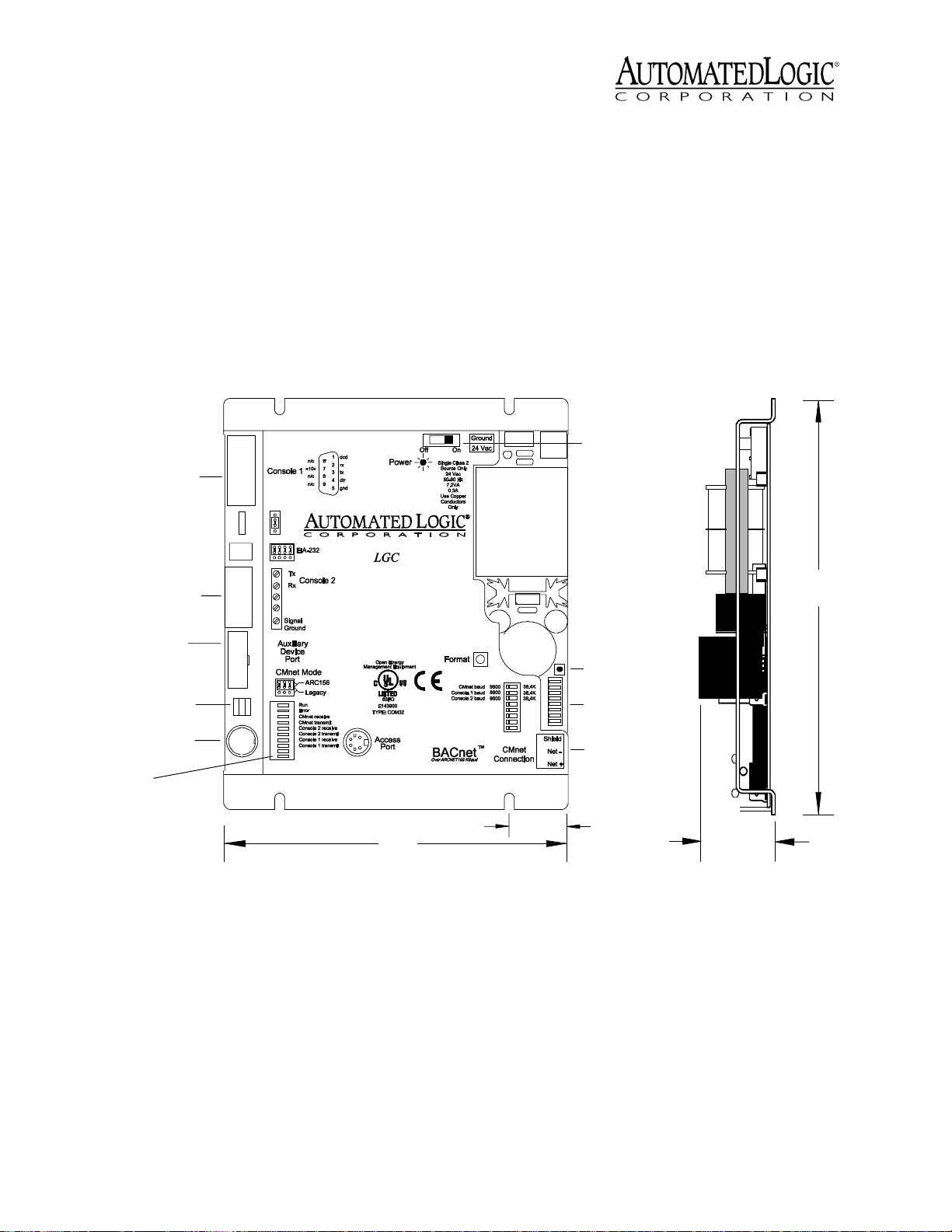
Power Switch
71/8"
Auxiliary
Device Port
CMnet Baud
Rate Jumper
Access Port
LEDs
61/4"
Figure 1. Module dimensions and layout
NOTE
This equipment has been tested and
found to comply with the limits for a Class A
digital device, pursuant to Part 15 of the FCC
Rules. These limits are designed to provide
reasonable protection against harmful
interference when the equipment is operated
in a commercial environment. This
equipment generates, uses, and can radiate
radio frequency energy and, if not installed
Manual Format
Button
Addressing
DIP Sw itch
CMn et
Connection
1"
15/8"
and used in accordance with the instruction
manual, may cause harmful interference to
radio communications. Operation of this
equipment in a residential area is likely to
cause harmful interference in which case the
user will be required to correct the
interference at his own expense.
Revised 6/16/00 • LGC 2 © 2000 Automated Logic Corporation
Page 3

Specifications
Power
Communications
Environmental Operating Range
Status Indication
Memory
Protection
Bat t e ry
Listed By
24VAC ±10%, 0.3A [(7.2VA), 5060Hz, power consumption] (single Class
2 source only, 100VA or less).
CMnet Port with EIA-485,
twisted pair, selectable for 156 kbps, 38.4
kbps, or 9600 bps. Two Console Ports,
selectable for 38.4 kbps or 9600 bps, for
direct connect or modem. One Access
Port for direct network using an APT. One
Auxiliary Device Port for a keypad/
display.
0 to
130°F (-17.8 to 54.4°C); 10 to 90% relative
humidity, non-condensing.
Visual (LED) status of
Console Port 1 and CMnet
communications, errors, running, and
power.
1MB Flash, 1MB RAM.
Built-in surge and transient
protection circuitry.
7-year lithium BR2325 battery
provides a minimum of 10,000 hours of
data retention during power outages.
UL 916 (PAZX), cUL C22.2
No.205 - M1983 (PAZX7), FCC Part 15 Subpart B - Class A.
Mounting
Screw the LGC into an enclosed panel using
the mounting holes provided on the cover
plate. Be sure to leave about 2 inches (5
centimeters) on each side for wiring.
BACview
the auxiliary device port.
You must use SuperVision to transfer memory
to the LGC. You can connect a portable
computer running SuperVision to the LGC
using the module’s Access port. For more
information about connecting to a
workstation, refer to “Formatting the Module”
on page 6.
1
or BACview2 keypad display unit to
Power
CAUTION
device (less than 30VAC, 100VA maximum).
Take appropriate isolation measures when
mounting the LGC module in a control panel
where non-class 2 devices or wiring are
present.
You can power several modules from the
same transformer if you maintain the same
polarity.
The LGC has an operating range of 21.6VAC
to 26.4VAC. If voltage measured at the
module’s power input terminals is outside this
range, the module may not work properly.
Since the module’s address is factory-set as
#1, you do not need to set the address.
1. Turn the module’s power off. This
prevents the module from being powered
up before the proper voltage is verified.
2. Make sure the 24VAC power source is off.
The LGC module is a Class 2
CAUTION
unit not expressly approved by the party
responsible for compliance could void the
user’s authority to operate equipment.
Changes or modifications to this
Wiring
The LGC connects to the CMnet through a
CMnet Connection port. The LGC also
provides an EIA-232 port for diagnostic
purposes. You can connect an optional
Revised 6/16/00 • LGC 3 © 2000 Automated Logic Corporation
3. Connect the power wires to the module’s
power terminals labeled Ground and
24VAC (see Figure 1 on page 2 for
location).
4. Apply power to the transformer.
5. Make sure that 24VAC is present at the
module’s power input terminals.
When the module turns on, the Run and
Error LEDs turn on and the Run LED
begins blinking. See Table 2 on page 7 to
Page 4

troubleshoot the LEDs. If the module does
not respond, call Technical Support at
(770) 429-3002.
Communications Wiring
The LGC can connect to the CMnet at 9600
bps, 38.4 kbps, or 156 kbps. When
communicating at 156 kbps, the CMnet uses a
unique implementation of the industry
standard ARCNET protocol called ARC156.
For a summary of the differences between
ARCNET and ARC156, please refer to
CMnet Wiring Technical Instructions
ARC156
.
Baud 156K
Bau d 156K
Baud 9 600/38.4K
Consolebaud 9600
address
(Module)
CMnetbaud 9600
LGnet
38.4K
38.4K
On
Off
4
2
1
Figure 2. Using an ARC156 CMnet
Use the appropriate wire for CMnet
communications. When using the ARC156
protocol, use an A3ARC156 wire available
from:
Magnum Cable Corporation
Cleveland, OH 44110-0500
(800) 421-0820
Use a dedicated 22AWG to 18AWG twisted
pair EIA-485) for legacy CMnet wiring. For
more information about CMnet wiring, refer
to the
Technical Handbook
CMnet Wiring Technical Instructions
or to
ARC156
.
1. Turn off the power.
2. Attach the two CMnet EIA-485
communications wires to the CMnet
Connection port labeled Net - and Net +
on the LGC (see Figure 1 on page 2). On
an ARC156 CMnet, you must also connect
the Shield.
Be sure to follow the same polarity as
used throughout the rest of the CMnet.
3. Make sure the LGC is configured for the
correct baud rate. All modules on the
CMnet must use the same baud rate.
On an ARC156 CMnet, set the CMnet Baud
Rate jumper to Baud 156K. Refer to Figure
2 for the jumper’s location.
If you are using a legacy CMnet, set the
CMnet Baud Rate jumper to Baud 9600/
38.4K and select the proper speed with
the first switch on the Addressing DIP
switch. Refer to Figure 3 for the switch’s
location.
CMnet Baud 9600
Baud 9600/38.4 K
Bau d 156K
Baud 9 600/38.4K
Console 1 Baud 9600
Console 2 Baud 9600
CMnetbaud 9600
Consolebaud 9600
LGnet
Off
address
4
2
(Module)
1
Figure 3. Using a Legacy CMnet
38.4K
38.4K
38.4K
38.4K
38.4K
On
Addressing
The LGC’s address is factory-set as control
module #1 and cannot be changed.
Transferring Memory
The LGC module stores the LGM module
driver. To transfer the module driver to the
LGC, you must use SuperVision v2.6 or later
software, and you must use FBLINK version
2.7a or later. For more information about
using SuperVision, refer to the
User’s Guide
.
SuperVision
Revised 6/16/00 • LGC 4 © 2000 Automated Logic Corporation
Page 5

The first memory transfer to the LGC takes
9
Rx
6
1
2-Tx out
3-Rx in
5-Gnd
1,6,8-+10V or floating
Tx +5V
APT
5
Exec. 4 relay
Isolate Network
Mode Select
TTL
485
ACCESS
PORT
EIA-232
Port
Mode Select
Switch
Exec. 4 relay
Switch
Access
Port
Ground
24Vac
Optiona
l
She
i
l
d
Net-
Net+
longer than subsequent memory transfers.
1. Log in to SuperVision on a workstation
connected to the CMnet. You can also
connect directly to the gateway using the
Access Port; see “Communicating with the
Workstation” .
2. Navigate to the module driver and look at
the module status page in SuperVision to
make sure the gateway type and number
agree with the module.
• To view the module status page in
SuperVision v3.0, click Tools Troubleshooting - Module Status.
• To view the module status page in
SuperVision v2.6, press the Esc key,
type
MO ,,module address,15
and press Enter.
3. Transfer memory to the module.
• In SuperVision v3.0, click Tools Troubleshooting - Transfer Memory to
Module.
• In SuperVision v2.6, choose Download
Memory for This Module.
When the memory transfer is finished, check
the module status page again. Make sure the
FB List shows all the FBs you intended to
transfer.
Figure 4. Using the Access Port
speed for each Console Port is set individually
using the eight-position DIP switch. DIP
switch 1 sets the baud rate for Console Port 1
and switch 2 set the baud rate for Console
Port 2 (see Figure 3 on page 4). Use the wiring
diagrams in Figure 5 on page 6 to connect a
Console Port to a workstation or a modem.
Use the following procedure to connect the
Access Port to a workstation.
1. Connect the computer’s serial port to the
EIA-232 port of the APT using a standard
straight-through cable (see Figure 4).
2. Set the APT’s Mode Select switch.
• On an ARC156 CMnet, use the TTL
setting.
• On a legacy CMnet, use the 485 setting.
3. Connect the Access Port of the APT to the
Access Port of the module.
Troubleshooting
4. In SuperVision, define the connection type
using Table 1
Communicating with the Workstation
The LGC can connect to a workstation
through the Access port using an APT (see
Figure 4) or through the Console Ports. A
Console Port can connect directly to the
workstation’s serial port or to a modem,
through which you can dial the workstation.
The LGC’s Console Ports can communicate at
9600 bps or 38.4 kbps. The communication
Revised 6/16/00 • LGC 5 © 2000 Automated Logic Corporation
Table 1. Connection Types
SuperVision
Vers i o n
3.0 any n/a Access Port
2.6 ARC156 yes Direct Connect
2.6 ARC156 no Direct Network
2.6 legacy n/a Direct Network
Typ e o f
CMnet
Gateway
Present?
Use Connection
Type
Page 6

Console Po rt
(9 pin )
*DCD 1
RX 2
TX 3
*DTR 4
GND 5
Console Port 1
Workstation
(9 pin)
4DTR*
3TX
2RX
1 DCD*
5GND
Console P ort 2
Console Port
(5 pin)
TX 1
RX 2
GND 5
Workstation
(9 pin)
2RX
3TX
5GND
Console Port
(9 pin )
*DCD 1
RX 2
TX 3
*DT R 4
GND 5
Console Port
(9 pin)
*DCD 1
RX 2
TX 3
*DT R 4
GND 5
*DS R 6
**RTS 7
**CT S 8
*RI 9
W orkstation
(25 pin)
20 DTR*
2TX
3RX
8 DCD*
7GND
Modem
(25 pin )
8 DCD*
3RX
2TX
20 DTR*
7GND
6DSR*
4RTS**
5CTS**
22 RI*
Console P ort
GND 5
Console Port
(5 pin)
TX 1
RX 2
*D TR 3
*DCD 4
GND 5
* W ire connection usually not needed
** N eeded only if hardware handshaking is used
† DCD can be hooked up to the DTR signal for
self-handshaking
Figure 5. Wir ing Diagrams
(5 pin)
TX 1
RX 2
Workstation
(25 pin)
3RX
2TX
7GND
Modem
(25 pin )
2 TX (receive input)
3 RX (transmit output)
20 DTR*†
8 DCD*†
7GND
The baud rate of the Access Port is
determined by the CMnet Baud Rate DIP
switch on the module.
2. Press and hold the Format button (see
Figure 1 on page 2 for location). While
continuing to hold the Format button, turn
the module’s power on.
Formatting the Module
When you are unable to communicate with a
module, you can, as a last resort, manually
format the module to try to restore
communication. Formatting the module
erases all memory, so you need to transfer
memory back to the module once it is
3. Continue to hold the button until the Error
LED flashes three times in sync with the
Run LED.
4. Release the Format button.
5. Transfer memory to the module. Refer to
“Addressing” on page 4.
formatted.
1. Turn the module’s power off.
Revised 6/16/00 • LGC 6 © 2000 Automated Logic Corporation
Page 7

LEDs
The LGC has several LED indicators to show
the status of certain functions. Table 2
explains the Run and Error LED signals in
detail to assist troubleshooting. See Figure 1
on page 2 for location of LED signals.
Table 2. LED Signals
Run LED Error LED Condition
5 flashes
per second
7 flashes
per second
Off Firmware transfer in
progress
7 flashes
per second
Ten second recovery
period after brownout
Power - indicates power is being supplied to
the module.
CMnet receive -indicates when the LGC
receives data from the CMnet.
CMnet transmit - indicates when the LGC
transmits data over the CMnet.
Console receive - indicates when the Console
Port receives data.
Console transmit - indicates when the
Console Port transmits data.
An - blinks to indicate network activity.
Table 2. LED Signals
Run LED Error LED Condition
2 flashes
per second
2 flashes
per second
2 flashes
per second
Off Normal
1 flash per
second
2 flashes
alternating
per second
Normal, but module is
alone on the CMnet
Five minute auto-restart
delay after system error
14 flashes
per second
14 flashes
per second
Brownout
Protection
The LGC is protected by internal solid state
Polyswitches on the incoming power and
network lines. These Polyswitches are not
replaceable and will reset themselves if the
condition that caused the fault returns to
normal.
Production Date
To determine when a module was
manufactured, check the Module Status
report in SuperVision. Refer to the
User’s Guide
for more information about the
Module Status report.
A sticker on the back of the module also
shows the date the module was
manufactured. The first three characters on
the sticker indicate the type of module. The
next three characters show the year, month,
and week of manufacture. (The month digit is
in hexadecimal.)
SuperVision
2 flashes
per second
2 flashes
per second
2 flashes
per second
2 flashes
per second
5 flashes
per second
Revised 6/16/00 • LGC 7 © 2000 Automated Logic Corporation
2 flashes in
sync per
second
3 flashes
per second
4 flashes
per second
On Exec halted after frequent
On Exec start-up aborted, Boot
Module is configured for a
different baud rate than the
rest of the CMnet
Module has just been
formatted
Two or more items in the
database have the same
ARC156 CMnet address
system errors
is running
 Loading...