

Page 1

Technical Instructions
InterOP8500
Introduction 2
Specifications 3
Mounting 4
Connecting Expander Modules 4
Addressing 4
Power Wiring 5
Using the ALC Power Supply 6
Using the Johnson Power Supply 7
Network Communications 7
Communicating with the Workstation 8
Input/Output 9
Analog Inputs 9
Unswitched and Switched Inputs 10
Calculating Offset and Gain 12
Binary I/O Power Jumper 12
Binary Inputs 13
Binary Outputs 13
Point Identifiers 15
Point Identifiers in WebCTRL 15
Channel Numbers in SuperVision 15
Transferring Memory 17
Transferring Memory in WebCTRL 17
Transferring Memory in SuperVision 18
Troubleshooting 18
Formatting the Module 18
LEDs 18
Protection 19
Production Date 19
Sample GFB 20
Automated Logic Corporation • 1150 Roberts Blvd. • Kennesaw, GA 30144 • 770/429-3000 • 770/429-3001 Fax •
www.automatedlogic.com • Copyright 2001 Automated Logic Corporation. All rights reserved. Automated Logic, the
Automated Logic logo, SuperVision, Eikon, Alert, and InterOp are registered trademarks of Automated Logic
Corporation. WebCTRL is a trademark of Automated Logic Corporation. BACnet
All other brand and product names are trademarked by their respective companies.
®
is a registered trademark of ASHRAE.
Page 2
Introduction
The InterOP8500 mounts directly to a Johnson
Controls panel, replacing the Johnson FIC-1n1
control board and the PCR-102. The
InterOP8500 uses the same mounting
brackets and can be powered by the existing
power supply (using a special adaptor cable).
However, in order to retain the UL listing, the
RPA-105 and the LPS-105 must be replaced by
the PWRSUP8500.
In addition, the InterOP8500 uses the Johnson
field termination board (FTB-102) for binary
I/O and analog input. Please note that slave
FICs must be replaced by separate, standalone InterOP8500 modules.
The InterOP8500’s edge connector plugs
directly into the field termination board’s
socket. Once connected, the InterOp8500
accesses the binary and analog I/O, as well
as an isolated 12VDC power supply for its
binary outputs. The InterOP8500 board
contains the microprocessor, a connection
port for the network connection, and a port
for I/O expansion. The InterOP8500 has 8
binary inputs, 15 analog inputs (which can be
set to either RTD or voltage mode), and 16
digital outputs.
The Access Port allows communication with
WebCTRL or SuperVision. The InterOP8500's
keypad port provides the interface for serial
communications with a BACview
BACview
BACview
2
keypad display. Refer to the
1
or BACview
2
Hardware Technical
1
or
Instructions for more information on small
and large keypad display.
NOTE
NOTE A 24VAC power supply is required for
NOTENOTE
a keypad.
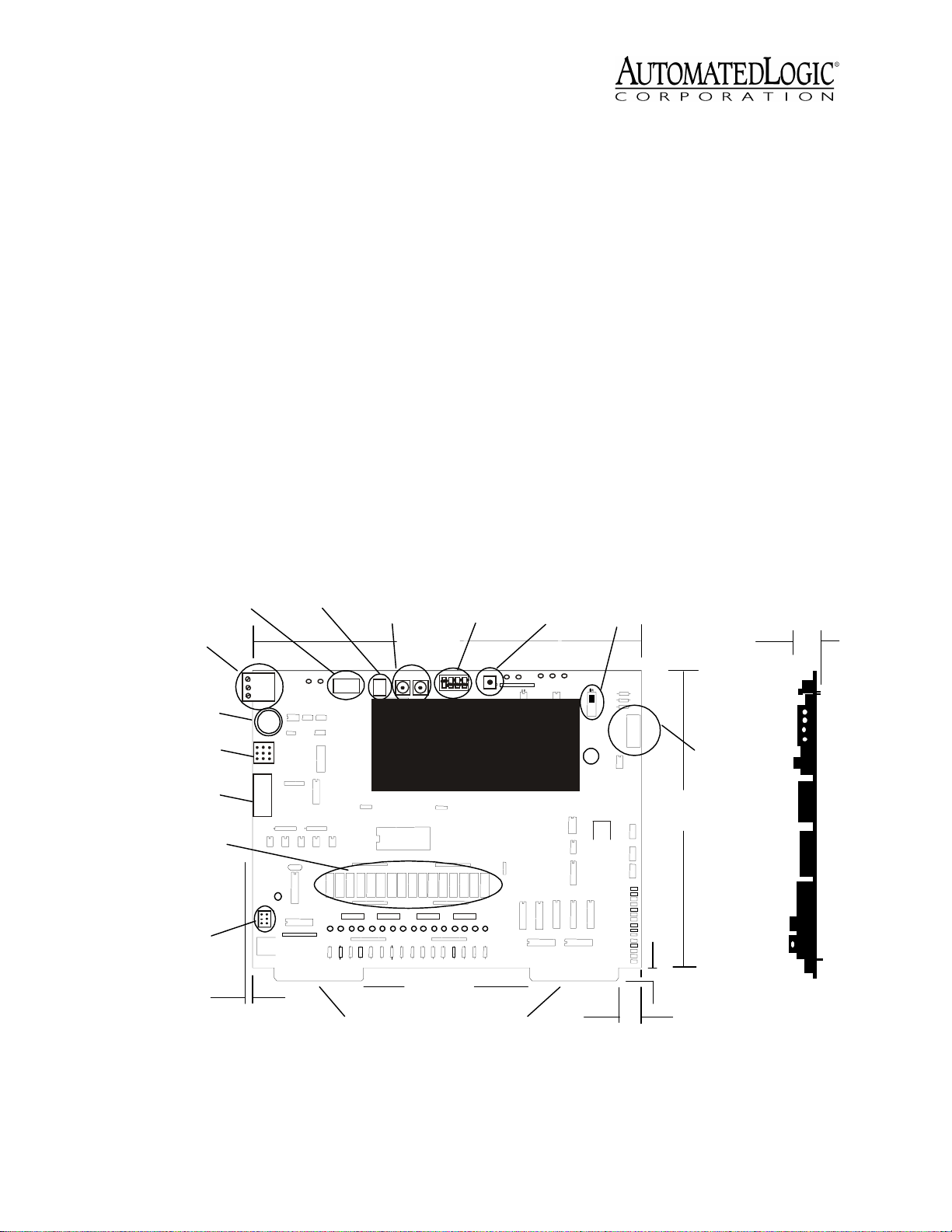
Keypad Port
CMnet
Terminal
Access
Port
Comm Mode
Jumper
Expander Port
Binary Output
HOA Switches
Binary I/O
PowerJumper
2/8"
.64 cm
Keypad
Power
Dual Rotary
Address
Binary I/O
Baud Rate
11 1/4"
28.58 cm
10's 1's
Binary Outputs
47/8"
12.38 cm
Switch
InterOp8500
Analog Inputs
Format
Button
Power
Switch
5/8"
1.59 cm
1"
2.5 cm
Power
Terminals
85/8"
21.9 cm
3/8"
.95 cm
Figure 1. InterOP8500 layout and dimensions
Revised 7/10/01 • InterOP8500 2 © 2001 Automated Logic Corporation
Page 3
The table below outlines the limitations and
s
requirements depending on whether you are
using WebCTRL or SuperVision to
communicate with your InterOP8500.
Specifications
Power 5VDC, 175mA (external), 275 mA
(internal).
12VDC, 25mA.
WebCTR L Super Vision
Module Driver DRV_InterO
P8500
Number of Function
Blocks*
Number of BACnet
Objects*
* depending on available memory
100 59
2000 1000
85M
For more information, see the appropriate
module driver document on the Automated
Logic website at www.automatedlogic.com.
12VDC, 175mA (external power), 25 mA
(internal power) supplied through the
card-edge connector.
24VAC, 300mA for use with the large
keypad/display.
Inputs 8 binary inputs, 15 analog inputs
(configurable for 1k ohm nickel RTD or 1
to 5V).
Input Resolution 12 bit A/D.
Digital Outputs 16 digital outputs,
12VDC, 300mA fused output.
Communication For WebCTRL, 156 kbps
BACnet-over-ARCNET and 9600 bps or
38.4 kbps EIA-485 BACnet MS/TP.
For SuperVision, 156 kbps BACnet-overARCNET, 9600 bps or 38.4 kbps Legacy
CMnet. Access Port:9600 bps or 38.4 kbps
EIA-485.
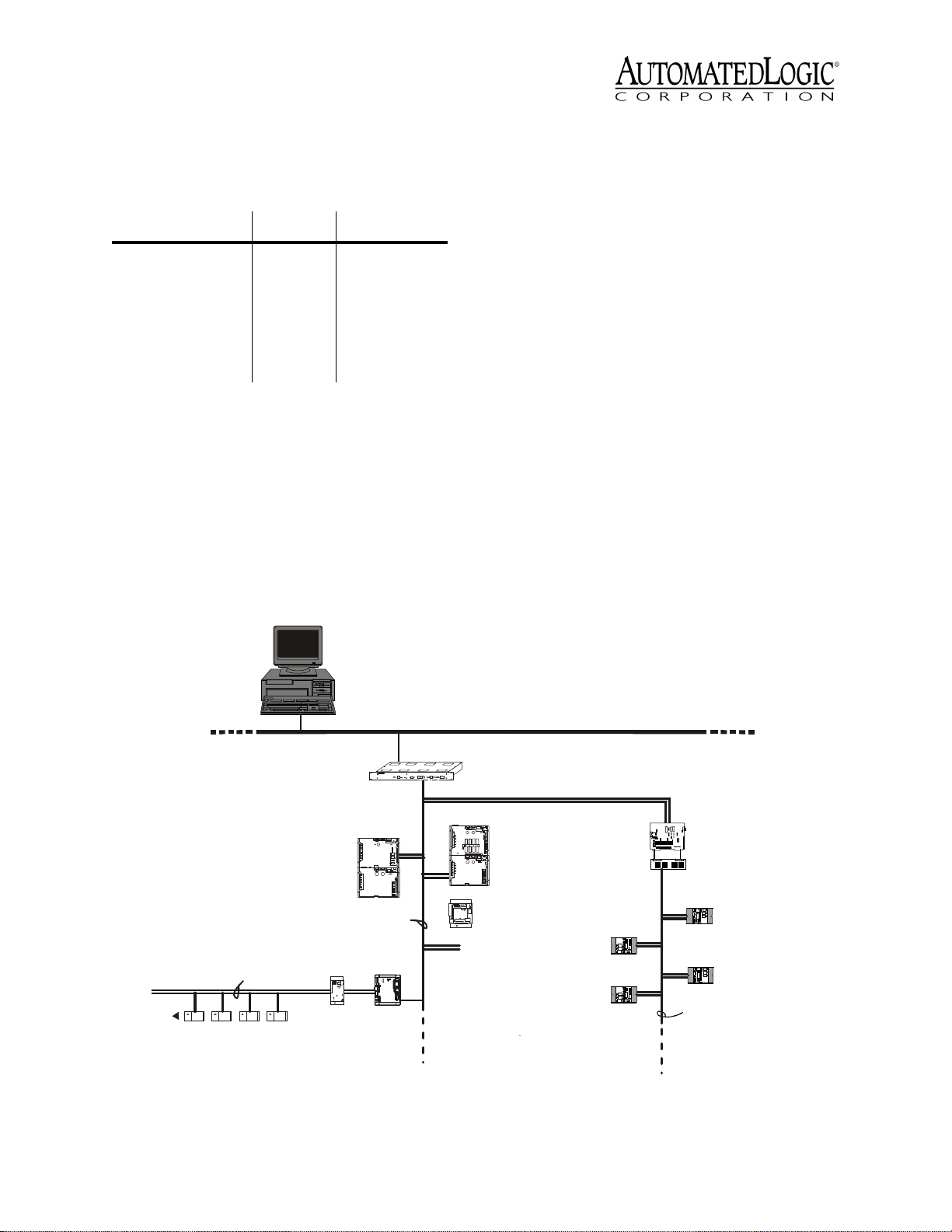
MX-Line
U-Line: 9600 bp s or 3840 0 b p s
U-Cards
LGRM-E
CMnet (ARC156)
UNI/32
TNPB
S-Line
Figure 2. Network Architecture
For WebCTRL, BACnet/IP.
For SuperVision, BAC net/Ether net.
MX-Line
Johnson
Field Device
Johnson
Field Device
InterO p85 00
John s o n Fie ld
Termination Board
Johnson
Field Device
Johnson
Field Device
John son I/O Dev ice
Revised 7/10/01 • InterOP8500 3 © 2001 Automated Logic Corporation
Page 4

Environmental Operating Range 0-
130 °F (-17.8 to 54.4 °C), 10 to 90%
relative humidity, non-condensing.
Status Indication Visual (LED) status of
CMnet communication, running, errors,
and power.
Memory 1MB Flash memory, 2MB non-
volatile battery-backed RAM (which
stores data even during power failures).
128 bytes of EEPROM.
Real Time Clock A battery-backed real
time clock that keeps track of time in the
event of a power failure.
Protection Surge and transient protection
circuitry.Optically isolated
communications.
Bat t e ry Seven-year lithium BR2330 battery
provides a minimum of 10,000 hours of
data retention during power outages.
Mounting
CAUTION
CAUTION Changes or modifications to this
CAUTIONCAUTION
unit not expressly approved by the party
responsible for compliance could void the
user's authority to operate the equipment.
place with the plastic retainers provided
in the panel.
4. Place the brushed aluminum ALC label on
the door of the panel.
Connecting Expander Modules
Up to five expansion Mx modules can be
connected to an InterOP8500. The stack can
be arranged in a single column using the
optional expansion cable.
NOTE
NOTE Use only one expansion cable per
NOTENOTE
stack.
Addressing
Before setting or changing the address, make
sure the InterOP8500’s power is off. The
InterOP8500 only reads the address when the
module is turned on. After changing the
address, you must transfer memory to the
module. Refer to “Transferring Memory” on
page 17.
The InterOP8500 has two rotary switches for
addressing:
1. Remove all power to the Johnson Controls
panel.
2. Open the face of the Johnson Controls
panel. The panel may contain up to three
Johnson Controls boards which face the
front of the panel and a side-mounted
board.The facing boards are stacked
above one another and are located
adjacent to the field termination board.
Remove the facing boards and any cables
(called "RPA wires") connected to them.
3. The InterOP8500 mounts directly to the
field termination board using either the
PWRSUP8500 or the existing power
supply (RPA-105 and LPS-105) as shown
in Figure 3 on page 5 and Figure 5 on page
6. Connect the InterOP8500 edge
connectors to the field termination
board's socket. Lock the InterOP8500 in
• For WebCTRL systems, use the switches
to assign the device’s MAC (medium
access control) address on the BACnetover-ARCNET network segment. The
rotary switches define the MAC address
portion of the device’s BACnet address
which is composed of the network
address and the MAC address.
• For SuperVision systems, use the
switches to assign the device’s module
number.
One switch corresponds to the tens digit and
the other corresponds to the ones digit. For
example, if the module’s address is three, set
the tens switch to zero and the ones switch to
three, as shown in Figure 4 on page 5.
Revised 7/10/01 • InterOP8500 4 © 2001 Automated Logic Corporation
Page 5
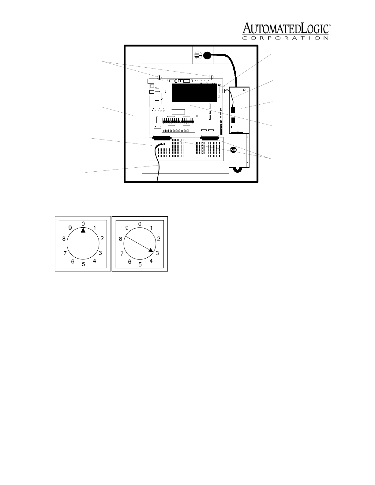
Plastic Retainer s
InterOp-8500
Power Connector
Power Cab le
Johnson Controls
Panel
Johnson Field
T e rmination Board
(FTB-102)
to External
Power Supply
Figure 3. InterOp8500/PWRSUP8500 mounted in Johnson Controls panel
10's 1's
Figure 4. Setting the CMnet address
Power Wiring
The InterOP8500 module is designed to
accept power directly from either the
PWRSUP8500 or the existing Johnson power
supply (LPS-105 and RPA-105). In order to
retain the UL listing of your system, a field
inspection is required if using a Johnson
power supply or the RPA-105 and the LPS-105
must be replaced by the PWRSUP8500 or.
Refer to “Using the ALC Power Supply” on
page 6 for wiring with the PWRSUP8500, or to
“Using the Johnson Power Supply” on page 7
for wiring with an existing Johnson power
supply.
PWRSUP8500
(side-mounted)
InterOp-8500
Edge Connectors
Whenever possible, make sure the module's
power and communications connections are
working properly before connecting any
inputs and outputs. Care should be taken to
isolate power wiring from all other wiring
inside the enclosure. The high and low
voltage wiring must be kept as far apart from
each other as is possible to avoid noise
interference.
NOTE
NOTE To protect analog signals from stray
NOTENOTE
noise and to minimize EMI, use shielded
cable on all signal wires and low voltage
power wires.
When entering, exiting, or interconnecting
with the enclosure, it is better to use several
small openings than one large one. The 12V
binary outputs are powered by a separate
source supplied through the field termination
board.
CAUTION
CAUTION The InterOP8500 module is a
CAUTIONCAUTION
Class 2 device (less than 30VAC.) Take
appropriate isolation measures when
mounting an InterOp8500 module where
non-Class 2 devices or wiring are present.
Revised 7/10/01 • InterOP8500 5 © 2001 Automated Logic Corporation
Page 6

Johnson Controls
Panel
Plastic Retainers
LPS-105
InterOp-8500
Edge Connectors
Johnson Field
Termination Board
(FTB-102)
to External
Power Supply
Figure 5. InterOp8500/RPA-105 and LPS-105 mounted in Johnson Controls panel
Using the ALC Power Supply
The PWRSUP8500 power supply replaces both
the Johnson Controls LPS-105 and Johnson
RPA-105. The PWRSUP8500 is designed to fit
into the previous power supply's mounting
bracket and power the InterOP8500. The
PWRSUP8500 does not require any adaptor
cables. It connects directly to the
InterOp8500's power connector.
CAUTION
CAUTION The PWRSUP8500 module is a
CAUTIONCAUTION
120VAC device. Take appropriate isolation
measures when mounting a PWRSUP8500.
1. Turn the power switches off on the
InterOP8500 and the Johnson Controls
panel.
2. Unplug the LPS-105 from the power outlet
(see Figure 5).
3. Remove the power cable from the
InterOP8500 power connector.
ON
OFF
J20
J23
Panel Power
Switch
Grounding Wire
(green)
RPA-105
(side-mounted)
Power Adapter
Cable
4. Take out the mounting screw from the
face of the LPS-105 and remove the LPS105 from the Johnson Controls panel.
5. Take out the mounting screw from the
back of the RPA-105 and remove the RPA105 from the Johnson Controls panel.
6. Place the PWRSUP8500 in the same
brackets that the RPA-105 was in. Make
sure the edges of the PWRSUP8500 are in
the slots.
7. Replace the mounting screw in the back
of the PWRSUP8500 (see Figure 3 on page
5).
8. Connect the power cable of the
PWRSUP8500 to the InterOP8500 power
connector and plug the PWRSUP8500 into
the power outlet.
9. After verifying that you have +5V on the
red and +12V on the blue, referenced to
the Gnd (black), turn the InterOp8500
power switch on.
Revised 7/10/01 • InterOP8500 6 © 2001 Automated Logic Corporation
Page 7

Using the Johnson Power Supply
1. Verify that the InterOP8500 is addressed
correctly.
2. Turn the Johnson Controls panel power
switch off.
3. Turn the InterOP8500 power switch off
(see Figure 1 on page 2).
4. Use the Power Adaptor Cable shown in
Figure 6 to connect power from the
Johnson power supply to the InterOP8500.
There is only one way for the connectors
on the cable to properly connect to the
indicated J terminals - do not force the
connectors on the wrong terminal.
5. Connect a grounding wire from the
chassis of the panel to the earth ground
terminal of the InterOp8500. See Figure 5
on page 6 for wiring.
6. Turn the InterOP8500 power switch on.
7. Turn the panel power switch on.
8. Make sure that the Communications
Power, Logic Power +5V, and Power +12V
LEDs are lit (located at the top edge of the
InterOp8500 board). See “LEDs” on
page 18.
Network Communications
The InterOP8500 module supports several
communications options through its CMnet
port.
On a SuperVision system, the InterOP8500
module can connect to a BACnet-overARCNET network segment at 156 kbps, or to
a legacy CMnet at 9600 bps or 38.4 kbps.
When communicating at 156 kbps, the
network segment uses a unique
implementation of the industry standard
BACnet-over-ARCNET protocol called
ARC156. For a summary of the differences
between ARCNET and ARC156, please refer to
ARC156 CMnet Wiring Technical Instructions.
Use the appropriate wire for network
communications. When using an ARC156
network, use an A3ARC156 wire available
from:
Magnum Cable Corporation
Cleveland, OH 44110-0500
(800) 421-0820
Use a dedicated 22AWG to 18AWG twisted
pair wire for legacy CMnet (EIA-485) wiring.
For more information about CMnet wiring,
refer to the Technical Handbook or to ARC156
CMnet Wiring Technical Instructions.
1. Be sure the module’s power is off before
J23
wiring it to the network.
2. Check the network communication wiring
for shorts and grounds.
J3
Figure 6. Power Cable
J20
3. Connect the appropriate communications
wires to the module’s screw terminals as
shown in Figure 7 on page 8. Be sure to
follow the same polarity as the rest of the
network.
4. Make sure the module is configured for
the correct baud rate. All modules on the
Revised 7/10/01 • InterOP8500 7 © 2001 Automated Logic Corporation
Page 8

ARC156
network segment
Switch Number
38.4K baud
9600 baud
1 2 3 4
O
N
CMnet
Access p ort
Comm Mode port
Figure 7. Wiring the Terminals
network segment must use the same baud
rate.
On an ARC156 network segment (156
kbps), set the Comm Mode jumper to
ARC156 (see Figure 8 for the switch’s
location). The baud rate selection does
not matter in this case.
Comm Mode
CMnet
ARC156
Figure 10. Setting the baud rate DIP switch
You can verify that the InterOP8500 is
communicating on the network segment by
making sure the transmit and receive LEDs
are active.
Communicating with the Wo r k s tat i o n
When using SuperVision, you can connect a
workstation or portable computer directly to
the InterOP8500 module using an APT and the
module’s Access Port (see Figure 11). This
type of connection can be used to
troubleshoot the module or transfer memory.
If you are using an ARC156 network segment,
you can receive colors while connected to a
module’s Access Port if a gateway module is
on the network segment. You cannot receive
alarms through the Access Port, however.
Figure 8. Using an ARC156 Network Segment
If you are using a legacy CMnet (9600 bps
or 38.4 kbps), set the Comm Mode jumper
to CMnet, and use the baud rate DIP
switch to determine the baud rate (see
Figure 9 and Figure 10).
NOTE
NOTE Setting the Comm Mode jumper
NOTENOTE
to CMnet disables the industry standard
BACnet-over-ARCNET (ARC156) protocol
for the network segment and enables the
proprietary ALC CMnet protocol.
Comm Mode
CMnet
Figure 9. Setting the Mode Select for CMnet
ARC156
InterOp-8500
APT
ACCESS
PORT
EIA-232
Port
Mode Select
TTL
Mode Select
Switch
Access
Port
485
Figure 11. Usi ng the Access Port
The baud rate of the Access port is
determined by the first switch on the eightposition DIP switch (see Figure 7). If you need
to change the switch’s position, turn the
InterOP8500 module off first. Once you have
adjusted the switch, turn the module back on.
Revised 7/10/01 • InterOP8500 8 © 2001 Automated Logic Corporation
Page 9

1. Connect the computer’s serial port to the
EIA-232 port of the APT using a standard
straight-through serial cable.
2. Set the APT’s Mode Select switch.
• On an ARC156 network segment, use
the TTL setting.
Table 2. Cable Selection Guide
Field
Device
AQ-4101
I/O
Typ e
BO 18 2 200/61
A1 18 3 250/76
Conduct
or Size
(AWG)
Number
Required
Maximum
Cable
Length
(ft/m)
• On a legacy CMnet, use the 485 setting.
3. Connect the Access port of the APT to the
Access port of the module.
4. In SuperVision, define the connection type
using Table 1.
Table 1. Connection Types
SuperVision
Ver s i o n
3.0 any n/a Access Port
2.6 ARC156 yes Direct Connect
2.6 ARC156 no Direct Network
2.6 legacy n/a Direct Network
Type o f
CMnet
Gateway
Present?
Use Connection
Type
Input/Output
The InterOP8500 is equipped with 8 binary
inputs, 15 analog inputs, and 16 binary
outputs. Any of the analog inputs can be used
as digital inputs. Table 2 summarizes the
requirements for conductors between the
Johnson Controls field devices and the
termination board.
All wiring to remote devices must be kept
separate from power wiring in the area.
Exposed drain wire at the termination board
should be kept as short as possible, not
exceeding two inches (5 centimeters). All field
devices should be terminated using a
correctly sized wire nut or, when terminals
are provided, a solderless crimp-type
connection should be made.
EPT-101
H-6210 A1 18 2 250/76
N-9510 BO 18 2 200/61
PC-6100 A1 18 2 250/76
PET-101 A1 18 2 250/76
RTB-101
PQ-1001 A1 18 2 250/76
TE-Series A1 18 2 250/76
V-9010 BO 18 2 200/61
V-9012 POS/
Power
Supply
BO 18 2 200/61
A1 18 3 250/76
BO 18 2 200/61
BI 18 2 1000/305
18 2 200/61
INC
—18 2 —
Analog Inputs
The InterOP8500 provides access to 15 analog
inputs through the Johnson Controls field
termination board. Use the formulas in the
“Calculating Offset and Gain” on page 12
section to read signals from these inputs.
There are four field terminals for each AI
point 1 through 7, and five for each AI point 8
through 15 (see Figure 12 on page 10). The
function of these terminals is as follows:
Termination Row 1 This terminal is for
analog inputs and is connected to a
multiplexer.
Termination Row 2 This terminal is
connected to a regulated +2.5VDC supply.
Revised 7/10/01 • InterOP8500 9 © 2001 Automated Logic Corporation
Page 10

Termination Row 3 This terminal is the
unswitched input signal common.
Termination Row 4 This terminal is not
used.
Termination Row 5 This terminal is the
switched input signal common and is
available only on AI points 8 through 15.
Table 3. Acceptable Analog Input Signals
Analog Input
Type Power Jumper? Switched?
RTD thermistor
0-5VDC linear
0-2.5VDC linear
4-20mA linear
(Offset/Gain
setup as
1-5VDC)
Internal Yes Unswitched
Internal No Switched or
Unswitched
Internal No Switched or
Unswitched
External (plus
No Unswitched
parallel 250
ohm resistor)
Unswitched and Switched Inputs
Unswitched inputs, the most common type of
input, reference the sensor to the module's
ground, the same ground referenced by all
other unswitched input sensors. This type of
input is for devices that are "floating,"
meaning that they are not ground referenced
anywhere. Examples would be RTD inputs or
dry contacts.
Switched inputs are selected one at a time,
and the circuit board's ground is then
referenced to the module's "Switched
Ground" lead. This feature allows modules
that are not floating, and that may have a
small amount of ground shift, to give stable
readings on their AIs. Examples would be 05VDC or 0-2.5VDC devices.
NOTE
NOTE The channel number is not affected
NOTENOTE
by the input's condition (switched or
unswitched).
Input from external
+12VD C P ower Supply
Binary Inputs
Binary Comm on
Unused
Analog Inputs
+2.5 VDC
Analog Com mon
(Unswitched)
Unused
4
2
3
1
5
8
BI #
1
1
2
3
+-
12 VDC
2
3
4
5
BO #
67
1
2
3
8
4
5
AI #
2
3
1
566677
4
11
2
3
4
Binary Outpu ts
Binary Com mon
Unused
2
3
4
5
89
10
Figure 12. I/O Terminals for the Field Termination Board
11
121314 15
Analog Inputs
+2.5 VDC
Analog Com mon
(Unswitched)
Unused
Switc hed
Comm on
Revised 7/10/01 • InterOP8500 10 © 2001 Automated Logic Corporation
Page 11

1. Turn the Johnson panel power switch off.
2. Determine the type of signal received by
the field termination board. Consult the
Johnson Controls manuals if necessary.
The InterOP8500 must be configured to
receive the same type of input as the
previously removed Johnson boards.
3. Set the InterOp8500 jumpers as follows:
• For RTD mode insert a jumper for the
individual input. The jumpers are
located along the lower right side of the
InterOP8500 board (see Figure 13).
NOTE
NOTE If using a solid-state current
NOTENOTE
switch on a digital input, the resistance
must drop low enough for the module to
recognize it.
• For voltage and potentiometer mode,
remove the jumpers. (Current mode can
be configured by adding an external
sense resistor. For 4-20mA use a 250
ohm resistor Figure 14). Turn the
InterOP8500's power switch on.
15
14
Unsw itched Inputs
Jumper in Place =
RTD Mode
Switched Inputs
Jumper Removed =
Voltage M ode
Figure 13. Analog Input Jumpers
13
12
11
10
Grip
Here
9
8
7
6
5
4
3
2
1
120 VAC
XX VAC
ungrounded
Field Termination
Board
As specified by the
sensor manufacturer.
Sensor
Isolated
DC Power
Supply
4-20mA
Transducer
250 ohm
resistor
InterOp8500
Connect to Analog Input
Connect to Analog Common (unswitched)
Figure 14. Analog Input Wiring for 4-20 mA Signal
Revised 7/10/01 • InterOP8500 11 © 2001 Automated Logic Corporation
Page 12

4. For each input, enter the point identifiers.
• In WebCTRL, enter the point number
and the point type on the Properties
page. For linear inputs, set the
minimum value and maximum value to
scale the point to engineering units.
For example, consider a 1 to 4.5V humidity
sensor with a relative humidity of 20 to 90%.
The voltage span is 3.5 volts (4.5V - 1V). The
user unit span is 70% (90% - 20%). Calculate
the gain and offset for a humidity sensor like
this:
• In SuperVision, enter the channel
number, offset, and gain using the
Configure Points or Point Help feature.
Valid channel numbers are listed in
“Channel Numbers in SuperVision” on
page 15.
5. To verify each input’s operation, have
each sensor create a known value and
compare it to the condition reported on
the FB’s Properties page in WebCTRL or
Status page in SuperVision.
Calculating Offset and Gain
You may need to calculate the offset and gain
for analog inputs to ensure the correct value
is read by the InterOP8500. You can also use
the custom translation table on the module
driver Parameter page to read nonlinear
signals from these inputs. Refer to the
“Channel Numbers in SuperVision” on
page 15 for details.
GAIN
= 70%
= 70% 178.5
= 0.392
OFFSET
Here is an example of a 0 to 2.5V V-9012
feedback sensor with a range of 0 to 100%
relative humidity. The voltage span is 2.5V
(2.5V - 0) and the user unit span is 100%
(100% - 0%). Calculate the gain and offset for
a V-9012 feedback sensor like this:
GAIN
= 0. 392
= 0.392 51.2
= 19.07
= 100%
= 100% 127.5
= 0.78
256 3.5 volt s
*
5 volt s
256 1 vol t
*
*
5 volts
*
256 2.5 volt s
*
5 volt s
Use this formula to calculate the gain for an
analog input point:
GAIN
= us er unit
256 voltage span
*
5 volt s
OFFSET
= 0.78
= 0.392 0
= 0
256 0 volts
*
*
*
5 volts
Binary I/O Power Jumper
Use this formula to calculate the offset for an
analog input point:
OFFSET
Revised 7/10/01 • InterOP8500 12 © 2001 Automated Logic Corporation
= GAIN
256 mi n i mu m volt age
*
*
5 volts
The InterOP8500 provides a jumper (see
Figure 1 on page 2 for location) for selecting
between internal and external power for
Binary I/O points. The InterOP8500 provides
isolation for externally powered devices and
no isolation for internally powered devices. If
binary outputs are present, they must be
externally powered and the jumper must be
set to the External position (see Figure 15 on
page 13). If no binary outputs are present,
Page 13

then binary inputs can be internally powered
(no isolation) or externally powered
(isolated). Note the orientation of the
jumpers.
Grip
Here
analog supply ground coming from the RPA-
105.
NOTE
NOTE All eight binary input terminals are
NOTENOTE
electrically connected on the field termination
board. To prevent ground loops, electrically
isolate the sources of the binary input signals
from each other.
Internal Power
(no isolation)
Figure 15. Binary I/O Power Jumper
External Power
(isolated)
Binary Inputs
The InterOP8500 provides 8 binary inputs
with direct connection to the Johnson field
termination board. The inputs are for signals
in the range of -38VDC up to +38VDC. A
digital input microblock indicates On for any
voltage between -38.0VDC and 0.9VDC; it
indicates Off for any voltage between 2.5VDC
and 38.0VDC. These inputs are capable of
counting up to 1,000 pulses per second for
use in pulse-counting configurations. Each
binary input can sense either a set of nonenergized contacts, or a two-state DC voltage
level.
The field termination board contains three
terminals for each binary input point (see
Figure 12 on page 10):
Binary Outputs
The InterOP8500 provides 16 binary outputs
with a direct connection to the field
termination board. The 16 binary outputs
have suppression. The binary output power
requirement is 13.2VDC, which should be
supplied by an external Class 2 power supply.
The output of this external power supply is
connected to a pair of field terminals located
on the field termination board (see Figure 12
on page 10 for location). The maximum load
through each binary output is 200mA.
The field termination board has terminal
capacity for between 8 and 16 points
depending upon the types of output signals
provided. Each of the eight BO points located
on the termination board consists of six field
terminals. Each of these six field terminals
can provide either one or two independently
controlled binary output points. The function
of these terminals is as follows:
Termination Row 1 This terminal is
connected to an input buffer (each input
has a separate buffer).
Termination Rows 1-2 These terminals
are independently connected to either
+12VDC or isolated common (depending on
Termination Row 2 This terminal is the
input signal common.
Termination Row 3 Do not use terminal 3
unless you need to connect an earth
ground.
The common terminals for the binary inputs
application).
Termination Rows 3-4 These terminals
are connected to isolated common. They are
used with terminals 1 and 2 for fixed-polarity
signals.
are joined to the common terminals for the
binary outputs. All common terminals are
joined to the isolated 12VDC supply's
Termination Rows 5-6 These terminals
are unused.
negative terminal through the field
NOTE
NOTE Terminals 1, 2, 3, and 4 must not be
termination board. This binary ground is
isolated and independent of the logic and
Revised 7/10/01 • InterOP8500 13 © 2001 Automated Logic Corporation
NOTENOTE
grounded. Voltages from field devices must
Page 14

not be fed back into the binary output
terminals.
Three types of output signals are available:
momentary, position, and maintained. The
momentary signal is used to control a
maintained or momentary relay
configuration. The position signal is intended
to control an actuator with a position
transducer or other interface device. The
maintained signal is intended to control a
two-position device by delivering a
maintained 0 or 12VDC signal.
Manual Operation
The HOA switches (SW3 through SW18),
located as shown in Figure 1 on page 2, allow
each binary output to be in placed in Auto,
On, or Off mode (as shown in Figure 16).
AUTO
OFF
ON
SW3 SW4 SW5 SW17 SW18
LED8 LED9 LED10 LED22 LED23
Figure 16. InterOp8500 HOA switches
AUTO
OFF
ON
To verify each output’s operation, lock the
output to a known condition using the
Function Block’s Properties page in WebCTRL
or Parameter page in SuperVision. Be sure the
equipment operates as specified.
SuperVision, assign each switch a digital
input in the FB using channel numbers 81
through 80. Channel 81 corresponds to HOA
switch number one, channel 82 corresponds
to HOA switch two, and so on. Switches 10
through 15 use channel numbers 8A through
8F, and switch 16 uses channel number 80.
An off status means the HOA switch is in Auto
mode. An on status means the HOA switch is
in Manual mode.
Table 4. HOA Switch Positions
Output
Configuration On Off Auto
Normally open
output
Normally closed
output
Results on
Properties page
in WebCTRL* or
Status page in
SuperVision**
* use point type of HOA Status Feedback and point
number
** use channel numbers 81 - 80
DO
contacts
closed
DO
contacts
open
ON ON OFF
DO
contacts
open
DO
contacts
closed
determined
by FB
programming
determined
by FB
programming
Each digital output can be placed in Manual
or Auto mode by setting the HOA switches
(see Figure 1 on page 2 for the switches’
location). Table 4 shows the status of the
digital output based on the output’s
configuration and the HOA switch position.
You can monitor the status of the HOA
switches through WebCTRL or InterOP8500.
In WebCTRL, assign each switch a digital
input in the FB using the point number and
the HOA Status Feedback point type. In
Revised 7/10/01 • InterOP8500 14 © 2001 Automated Logic Corporation
Page 15

Point Identifiers
A point can be identified in WebCTRL by its
point number and point type; in SuperVision,
a point is identified by its channel number. On
both systems, expander number zero
represents I/O points on the InterOP8500.
Point Identifiers in WebCTRL
Enter the point identifiers in Eikon for
WebCTRL before the FB is made or on the
point’s Properties page in WebCTRL. Set the
type, number, and any other required
parameters for each point on the
InterOP8500.
1. Select a physical point type from the Point
Type field.
NOTE
NOTE To determine the physical point
NOTENOTE
type of an analog input, see Table 3 on
page 10.
2. If the physical point type is linear, enter
the appropriate minimum and maximum
present values on the microblock’s dialog
box.
For example, on a 0-5VDC sensor, enter 0
as the minimum and 5 as the maximum.
3. Enter the number of the input or output in
the Input or Output Number field.
NOTE
NOTE Points are numbered starting with
NOTENOTE
1 for each point type. For example, HOA
Status output numbers would start at 1
and could go up to 16; likewise, RTD input
numbers would start at 1 and could go up
to 15.
4. Enter an expander number if needed.
Channel Numbers in SuperVision
The following table shows the valid channel
numbers for each point on the InterOP8500.
The offset and gain values used depend on
the type of sensor or actuator attached to the
I/O point. You can select the channel number,
offset, and gain using SuperVision’s Point
Help feature or Configure Points utility.
Alternatively, you can preconfigure the points
by manually entering the channel number,
offset, and gain in Eikon using the values
shown in the following tables.
Table 5. Digital Output Channel Numbers
Point Signal T ype
DO 1
DO 2
DO 3
DO 4
DO 5
DO 6
DO 7
DO 8
DO 9
DO 10
DO 11
DO 12
DO 13
DO 14
DO 15
DO 16
† Use digital input microblocks to
monitor the status of HOA Switches.
Digital
HOA Status†1181
Digital
HOA Status†1282
Digital
HOA Status†1383
Digital
HOA Status†1484
Digital
HOA Status†1585
Digital
HOA Status†1686
Digital
HOA Status†1787
Digital
HOA Status†1888
Digital
HOA Status†1989
Digital
HOA Status†1A8A
Digital
HOA Status†1B8B
Digital
HOA Status†1C8C
Digital
HOA Status†1D8D
Digital
HOA Status†1E8E
Digital
HOA Status†1F8F
Digital
HOA Status†1080
Channel
Number
Revised 7/10/01 • InterOP8500 15 © 2001 Automated Logic Corporation
Page 16

Table 6. Input Channel Numbers
Point Signal Type
RTD 51
UI 1
mA or V olts 31
Digital 71
RTD 52
UI 2
mA or V olts 32
Digital 72
RTD 53
UI 3
mA or V olts 33
Digital 73
RTD 54
UI 4
mA or V olts 34
Digital 74
RTD 55
UI 5
mA or V olts 35
Digital 75
RTD 56
UI 6
mA or V olts 36
Digital 76
UI 7 RTD 57
mA or V olts 37
Digital 77
RTD 58
UI 8
mA or V olts 38
Digital 78
RTD 59
UI 9
mA or V olts 39
RTD 5A
UI 10
mA or V olts 3A
Channel
Number †Range Offset Gain
-50° to 250° F
-46° to 121° C
4 to 20mA
0 to 5V
-50° to 250° F
-46° to 121° C
4 to 20mA
0 to 5V
-50° to 250° F
-46° to 121° C
4 to 20mA
0 to 5V
-50° to 250° F
-46° to 121° C
4 to 20mA
0 to 5V
-50° to 250° F
-46° to 121° C
4 to 20mA
0 to 5V
-50° to 250° F
-46° to 121° C
4 to 20mA
0 to 5V
-50° to 250° F
-46° to 121° C
4 to 20mA
0 to 5V
-50° to 250° F
-46° to 121° C
4 to 20mA
0 to 5V
-50° to 250° F
-46° to 121° C
4 to 20mA
0 to 5V
-50° to 250° F
-46° to 121° C
4 to 20mA
0 to 5V
0.00
15.25‡
0.00
§§
0.00
15.25‡
0.00
§§
0.00
15.25‡
0.00
§§
0.00
15.25‡
0.00
§§
0.00
15.25‡
0.00
§§
0.00
15.25‡
0.00
§§
0.00
15.25‡
0.00
§§
0.00
15.25‡
0.00
§§
0.00
15.25‡
0.00
§§
0.00
15.25‡
0.00
§§
Table 6. Input Channel Numbers
Point Signal Type
RTD 5B
UI 11
mA or V olts 3B
RTD 5C
UI 12
mA or V olts 3C
RTD 5D
UI 13
mA or V olts 3D
RTD 5E
UI 14
mA or V olts 3E
RTD 5F
UI 15
mA or V olts 3F
† Celsius values can only be displayed in SuperVision when the Function
Block is made in Eikon v2.0 or later with the Metric option enabled. Refer to
the Eikon User’s Guide for more information.
§ Use the Point Configuration or Point Help feature available in SuperVision
v2.0 or later.
‡ Any adjustments needed to calibrate the RTD are done as offset adjustments
in the microblock.
Channel
Number †Range Offset Gain
-50° to 250° F
-46° to 121° C
4 to 20mA
0 to 5V
-50° to 250° F
-46° to 121° C
4 to 20mA
0 to 5V
-50° to 250° F
-46° to 121° C
4 to 20mA
0 to 5V
-50° to 250° F
-46° to 121° C
4 to 20mA
0 to 5V
-50° to 250° F
-46° to 121° C
4 to 20mA
0 to 5V
0.00
0.00
§§
0.00
0.00
§§
0.00
0.00
§§
0.00
0.00
§§
0.00
0.00
§§
15.25‡
15.25‡
15.25‡
15.25‡
15.25‡
Table 7. Maintained Binary Output
Channel Numbers across sections 1 and 3
Johnson Channel “xA”
(wired across terminal sections 1 and 3) ALC Channel
1A 11
2A 12
3A 13
4A 14
5A 15
6A 16
7A 17
8A 18
Revised 7/10/01 • InterOP8500 16 © 2001 Automated Logic Corporation
Page 17

Table 8. Maintained Binary Output
Channel Numbers across sections 2 and 4
Johnson Channel “xB”
(wired across terminal sections 1 and 3) ALC Channel
1B 19
2B 1A
3B 1B
4B 1C
5B 1D
6B 1E
7A 1F
8A 10
Table 9. Position Binary Output Channel
Numbers across sections 1 and 2
Channel Number Open Channel Number Closed
11 19
12 1A
13 1B
14 1C
15 1D
16 1E
17 1F
18 10
Transferring Memory
You should download memory whenever you
make changes to your modules (for example,
change the module number, upgrade the
module driver, or change the FB).
The InterOP8500 module can store one
module driver and several FBs. The number
of FBs stored depends on the software you
are using (see the table on page 3).
NOTE This type of download should be
performed with caution. When the module is
automatically restarted before and after
transferring memory, any equipment
controlled by the module is shut down and
restarted. Downloading memory also
overwrites all Function Blocks in the module
causing the module to lose any stored data.
Transferring Memory in WebCTRL
The InterOP8500 module using the
DRV_InterOP8500 module driver can store up
to 100 FBs, depending on their size. You must
be logged in to WebCTRL with the appropriate
privilege to download memory.
1. Click the CFG button at the bottom of the
navigation pane.
2. Click Download in the CFG tree control.
3. Click the Memory, Parameters, or
Schedules boxes, depending on what you
want to download.
NOTE A memory download includes a
parameter and schedule download.
4. Expand the tree in the action pane, click
the module you want to download to,
then click Add. Click on and Add any
other modules you want to download to.
5. Click the Execute Download button.
If any downloads failed, they are listed in
the Failures section under the tree in the
action pane. To retry a failed download,
click on the module in the Failures list,
click Add, and click the Execute
Download button again.
NOTE Since a failed download indicates
a system problem, you should never clear
a failure. Locate and resolve the problem,
then retry the download.
6. Click the Properties button to refresh the
screen. This removes the items from the
Download Items list.
Revised 7/10/01 • InterOP8500 17 © 2001 Automated Logic Corporation
Page 18

Transferring Memory in SuperVision
The InterOP8500 module using the 85M
module driver can store up to 59 FBs,
depending on their size.
1. Log in to SuperVision on a workstation
connected to the module network. You
can also connect directly to the module
using the Access Port; see
“Communicating with the Workstation” on
page 8.
2. Navigate to the module driver and look at
the module status report in SuperVision to
make sure the module type and number
agree with the module.
• To view the module status report in
SuperVision v3.0, click Tools Troubleshooting - Module Status.
• To view the module status report in
SuperVision v2.6b, press the Esc key,
type MO ,,module address,15 and
press Enter.
3. Transfer memory to the module.
• In SuperVision v3.0, click Tools Troubleshooting - Transfer Memory to
Module.
NOTE Since the module is automatically
formatted when you transfer memory, you
should only manually format the module if
communication was not established after the
memory transfer.
1. Turn the module’s power off. Make sure
the module’s address switches are not set
to ‘0 0’.
2. Press and hold the Format button (see
Figure 1 on page 2 for location).
3. While continuing to hold the Format
button, turn the module’s power on.
4. Continue to hold the button until the Error
LED flashes three times in sync with the
Run LED.
5. Release the Format button.
6. Transfer memory to the module. Refer to
“Transferring Memory” on page 17.
LEDs
The InterOP8500 module has several LED
indicators to show the status of certain
functions. Table 10 on page 19 explains the
Run (LED 3) and Error (LED 4) LED signals in
detail to assist troubleshooting.
• In SuperVision v2.6b, download
memory for This Module.
4. When the memory transfer is finished,
check the module status report again.
Make sure the FB List shows all the FBs
you intended to transfer.
Troubleshooting
LED 1 Rx - lights when the InterOP8500
receives data through the network segment.
LED 2 Tx - lights when the InterOP8500
transmits data over the network segment.
LED 5 Communications Power - Indicates
power is being supplied to the
communications circuitry.
Formatting the Module
If you are unable to communicate with a
module after transferring memory, you can,
as a last resort, manually format the module
to try to restore communication. Formatting
the module erases all memory, so you need to
transfer memory back to the module once it is
formatted.
Revised 7/10/01 • InterOP8500 18 © 2001 Automated Logic Corporation
LED 6 Logic Power +5V - indicates power is
being supplied to the logic circuitry.
LED 7 Power +12V - indicates power is
being supplied to the analog circuitry.
LED 8-23 Binary Outputs - indicates 12V
on the individual output.
Page 19

LED 24 Output Power - indicates power is
being received from field termination board
from the external power supply for binary
outputs and isolated binary inputs.
Table 10. LED Signals
Run LED Error LED Condition
2 flashes
per second
2 flashes
per second
2 flashes
per second
2 flashes
per second
2 flashes
per second
Off Normal
1 flash,
then pause
2 flashes,
alternating
with Run
LED
2 flashes,
in sync
with Run
LED, then
pause
3 flashes,
then off
Normal, but module is
alone on the CMnet
(this sequence doesn’t
occur in WebCTRL)
Five minute auto-restart
delay after system error
Module is configured for a
different baud rate than the
rest of the network
segment
Module has just been
formatted
Protection
The InterOP8500 module is protected by
internal solid state Polyswitches on the
incoming power and network connections.
These Polyswitches are not replaceable and
will reset themselves if the condition that
caused the fault returns to normal.
Production Date
To determine when a module was
manufactured, check the module status
report for the module in WebCTRL or
SuperVision. Refer to the appropriate user’s
guide for more information about the module
status report.
A sticker on the back of the module also
shows the date the module was
manufactured. The first three characters on
the sticker indicate the type of module. The
next two characters show the year and month
of manufacture.
2 flashes
per second
2 flashes
per second
5 flashes
per second
5 flashes
per second
7 flashes
per second
14 flashes
per second
4 flashes,
then pause
On Exec halted after frequent
On Exec start-up aborted, Boot
Off Firmware transfer in
7 flashes
per second,
alternating
with Run
LED
14 flashes
per second,
alternating
with Run
LED
Two or more devices on
this network have the
same ARC156 network
address
system errors or GFBs
halted
is running
progress, Boot is running
Ten second recovery
period after brownout
Brownout
Revised 7/10/01 • InterOP8500 19 © 2001 Automated Logic Corporation
Page 20

Sample GFB
Figure 17. Sample GFB
Revised 7/10/01 • InterOP8500 20 © 2001 Automated Logic Corporation
 Loading...