

Page 1

© 1999 Directed Electronics, Inc. Vista, CA N435A 12-99
®
Model 435
Installation Guide
®
Downloaded from: http://www.guardianalarms.net
Page 2

2 © 1999 Directed Electronics, Inc. Vista, CA
What Is Included . . . . . . . . . . . . . . . . . . . . . 3
Installation Points to Remember . . . . . . . . . . 4
Tools Required . . . . . . . . . . . . . . . . . . . . . . . 4
Deciding on Component Locations . . . . . . . . . 5
Siren . . . . . . . . . . . . . . . . . . . . . . . . . . 5
Control Module . . . . . . . . . . . . . . . . . . . . 5
Valet®/Program switch . . . . . . . . . . . . . . 6
Status LED . . . . . . . . . . . . . . . . . . . . . . 7
Starter Kill Relay . . . . . . . . . . . . . . . . . . 7
Finding the Wires You Need . . . . . . . . . . . . . . 8
Constant 12V . . . . . . . . . . . . . . . . . . . . . 8
Switched Ignition. . . . . . . . . . . . . . . . . . . 8
Parking Light Wire . . . . . . . . . . . . . . . . . 9
Door Switch Circuit . . . . . . . . . . . . . . . . . 9
Starter Wire . . . . . . . . . . . . . . . . . . . . . 10
Making Your Connections . . . . . . . . . . . . . . . 11
Solderless Butt Connections . . . . . . . . . . . 11
Solder Connections . . . . . . . . . . . . . . . . . 12
Primary Harness (H1), 12-Pin Connector . . . . 13
Primary Harness (H1) Wire Connection Guide . 14
Harness 2 (H2), Door Lock Outputs. . . . . . . . 19
Door Lock Harness (H2) Wire Connection Guide . 20
Positive-Triggered, Relay Driven
Systems (Type A) . . . . . . . . . . . . . . . . . . 20
Negative-Triggered, Relay Driven
Systems (Type B) . . . . . . . . . . . . . . . . . . 21
Reversing Polarity (Type C) . . . . . . . . . . . . 22
After-market Actuators (Type D). . . . . . . . . 23
Electrically Activated Vacuum (Type E) . . . . 24
One-Wire System, (Type F) . . . . . . . . . . . . 25
On-board Doubleguard
®
Shock Sensor . . . . . . 26
Auxiliary Harness (H3), 2-Pin Connector . . . . 26
Plug-In Harnesses. . . . . . . . . . . . . . . . . . . . 27
Super Bright LED . . . . . . . . . . . . . . . . . . 27
Valet®/Program Switch . . . . . . . . . . . . . . . 27
Programming Port . . . . . . . . . . . . . . . . . . 27
Four-Pin Optional Sensor Harness . . . . . . . . . 28
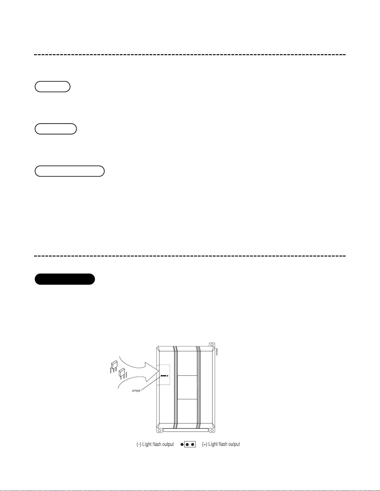
Internal Programming Jumper . . . . . . . . . . . 28
Light Flash Jumper . . . . . . . . . . . . . . . . . 28
System Features Learn Routine . . . . . . . . . . 29
Once A Feature Is Programmed . . . . . . . . . 30
To Access Another Feature . . . . . . . . . . . . 30
To Exit the Learn Routine . . . . . . . . . . . . . 30
System Features Menu. . . . . . . . . . . . . . . . . 30
Feature Descriptions . . . . . . . . . . . . . . . . . 31
Transmitter/Receiver Learn Routine . . . . . . . 32
Table of Zones . . . . . . . . . . . . . . . . . . . . . . 34
Long-Term Event History . . . . . . . . . . . . . . . 34
Rapid Resume Logic . . . . . . . . . . . . . . . . . . 35
Troubleshooting . . . . . . . . . . . . . . . . . . . . . 35
table of contents
Bitwriter™, Car★Com™, Code Hopping™, DEI®, Doubleguard®, ESP™, FailSafe®, Ghost Switch™,
Learn Routine™, Nite-Lite®, Nuisance Prevention Circuitry®, NPC®, Revenger®, Silent Mode™, Soft
Chirp®, Stinger®, Valet®, Vehicle Recovery System®, VRS®, and Warn Away® are all Trademarks or
Registered Trademarks of Directed Electronics, Inc.
Page 3
© 1999 Directed Electronics, Inc. Vista, CA 3
what is included
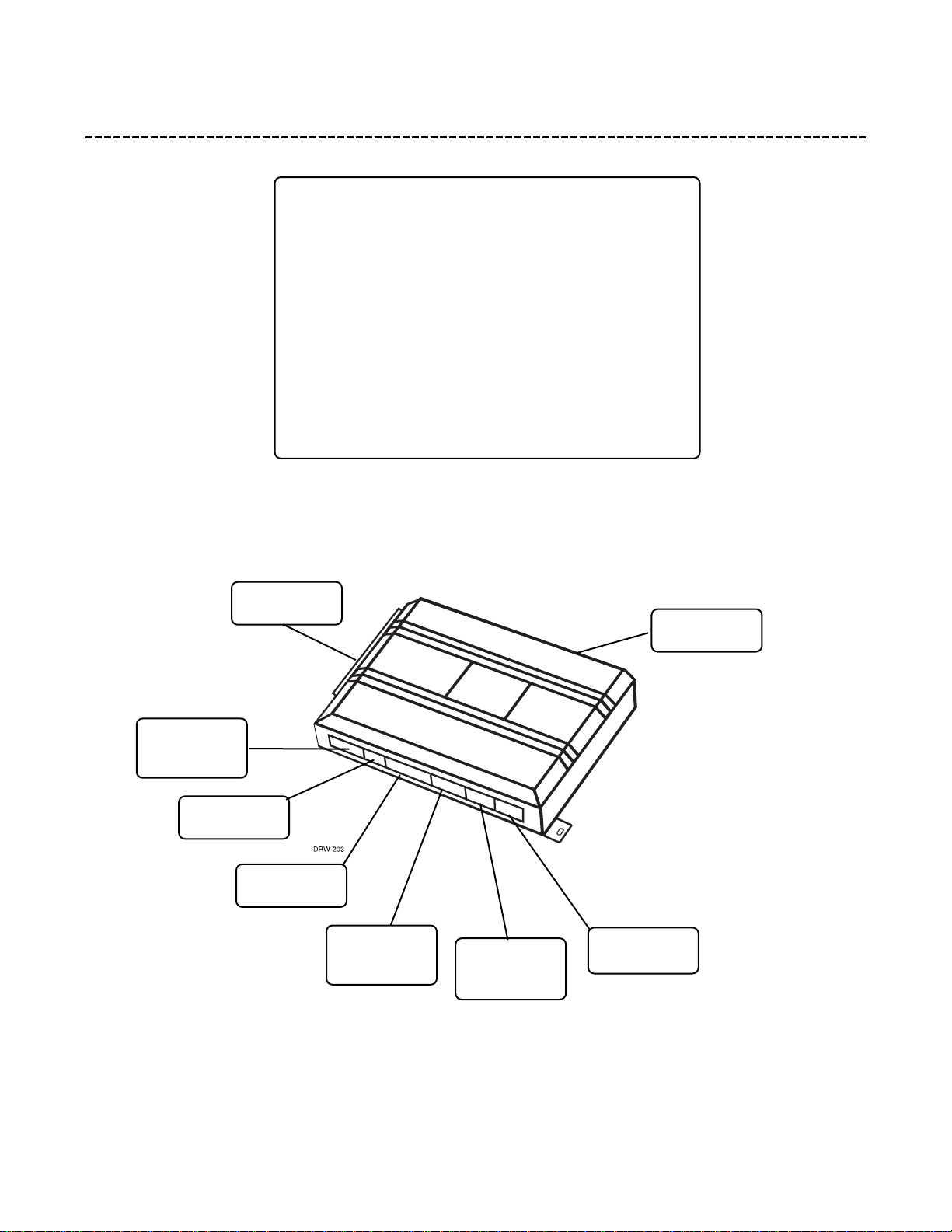
■ The control module (see diagram)
■ A Stinger
®
Doubleguard®shock sensor on-board
the control module
■ A Revenger
®
Soft Chirp®siren
■ Two 476A remote transmitters
■ The plug-in status LED
■ The plug-in Valet
®
/Program switch
■ Primary Harness
■ Door Lock Harness
■ 2-Pin Auxiliary Harness
■ Pre-wired FailSafe
®
Starter Kill Relay
Shock Sensor
Adjustment
Orange 2-Pin
Auxiliary Plug
Blue 2-Pin Mini
Valet/Program
Plug
Black 3-Pin
Data Input
Port
4-Pin Optional
Sensor Plug
2-Pin Micro
LED Plug
White 3-Pin
Door Lock
Harness Plug
Primary
Harness Plug
Page 4

4 © 1999 Directed Electronics, Inc. Vista, CA
installation points to remember
This product represents many years of research and development. It is very sophisticated and should be installed
by experienced security installers only. Please do not attempt installation of this product without reading this
guide. The system has been designed to provide the ultimate in security, coupled with limitless convenience and
expansion options.
This product is not intended for consumer installation and will have NO WARRANTY unless it is installed by an
authorized dealer.
Do not disconnect the battery if the vehicle has an anti-theft coded radio. If equipped with an airbag, avoid dis-
connecting the battery if possible.
IMPORTANT! Many airbag systems will display a diagnostic code through their warning light after
they lose power. Disconnecting the battery requires this code to be erased, a procedure that can
require a trip to the dealer.
Before beginning the installation:
■ Check with the customer to determine the Status LED location.
■ Remove the domelight fuse. This prevents accidentally draining the battery.
■ Roll down a window to avoid being locked out of the car.
After the install:
■ Test all functions. The “Using Your System” section of the Owner’s Guide is very helpful when testing.
■ When testing, don’t forget that this system is equipped with Nuisance Prevention
®
Circuitry. NPC™can bypass
both instant trigger zones, making them seem to stop working.
tools required
This is a general list of tools required to complete the installation of this DEI®security system in most vehicles.
Some vehicles may require additional tools.
■ Digital multi-meter
■ Wire cutters/strippers
■ Solderless terminal crimpers
■ Cordless power drill
■ Torx driver set
■ Nutdriver and/or socket set
■ Panel removal tool
■ Drill bit set
■ Phillips head screwdriver
■ Work light
Page 5
© 1999 Directed Electronics, Inc. Vista, CA 5
deciding on component locations
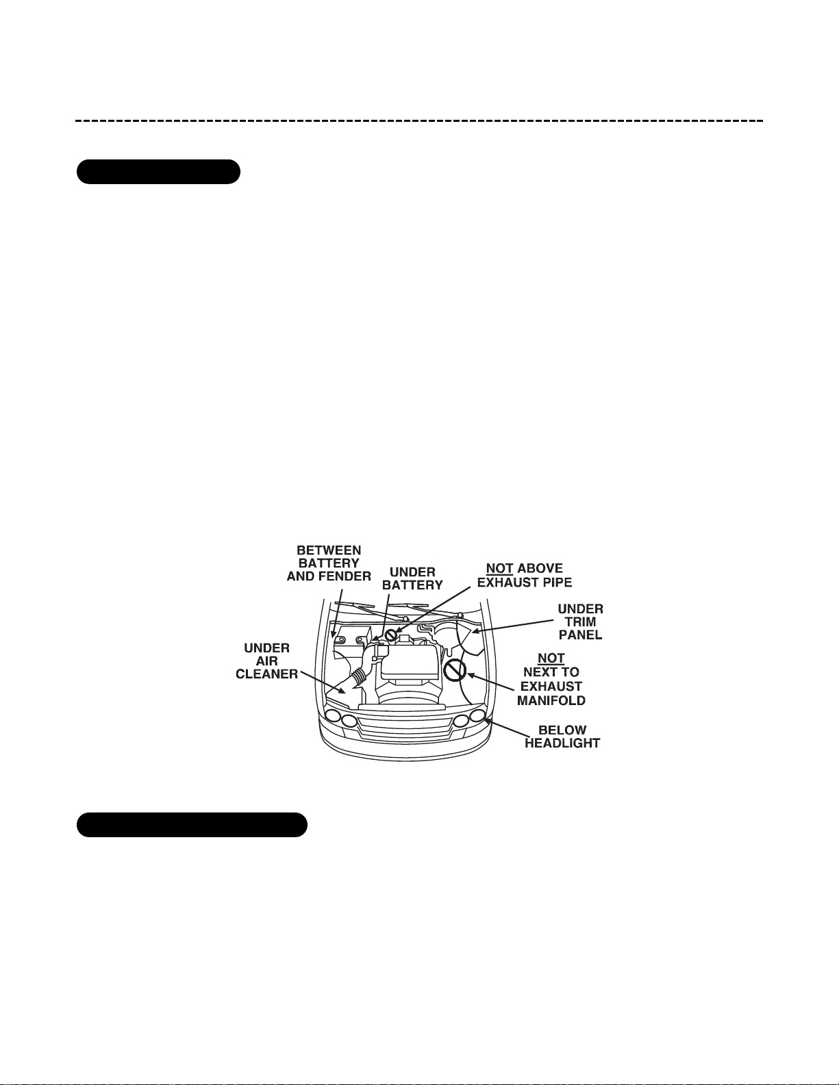
Some things to remember when mounting the siren:
■ Keep it away from heat sources. Radiators, exhaust manifolds, turbochargers, and heat shields are all things
to avoid.
■ Mount it where a thief cannot easily disconnect it, whether the hood is open or shut. Both the siren and its
wires should be difficult to find. This usually involves disguising the wire to look like a factory harness.
■ We recommend against grounding the siren to its mounting screws. Instead, we recommend running both the
red and black wires into the passenger compartment and grounding to one common point for all devices. Af-
ter all, both wires are the same length and come already bonded together. Whenever possible, conceal your
wires in the factory harnesses or in the same style loom as the factory.
■ When possible, put the siren on the same side of the vehicle as the control module, where its wires will reach
the control module’s wires without extending them. Always run the wires through the center of a grommet,
never through bare metal!
■ Point the siren down so water does not collect in it.
■ Never put the control module in the engine compartment!
■ The first step in hot-wiring a vehicle is removing the driver's side underdash panel to access the starter and
ignition wires. If the control module is placed just behind the driver's side dash it can easily be disconnected.
■ When locating the control module, try to find a secure location that will not require you to extend the har-
nesses’ wires (they are 1.5 meters long). Keep it away from the heater core (or any other heat sources) and
any obvious leaks.
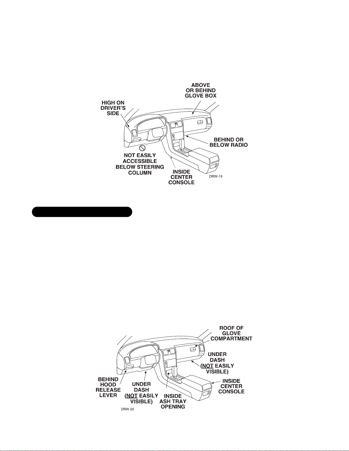
locations for the control module
locations for the siren
Page 6
6 © 1999 Directed Electronics, Inc. Vista, CA
■ The higher the control module is in the vehicle, the better the transmitter range will be. If you put the control
module under a seat or inside a metal dashboard, range will suffer.
■ Some good control module locations: Above the glove box, inside the center console, above the underdash
fuse box, above the radio, etc.
Ensure that the location you pick for the switch has sufficient clearance to the rear. The switch should be well
hidden. It should be placed so passengers or stored items (such as in a glove box or center console) cannot ac-
cidentally hit it. The switch fits in a
9
/32-inch hole.
This system has Remote Valet
®
. The user can enter and exit Valet®Mode without having to reach the
Valet
®
/Program switch. DEI®introduced this feature so that switch location was less critical in day-to-day use.
As long as the Valet
®
/Program switch can be reached to disarm without a transmitter, easy access is not important.
IMPORTANT! When the vehicle is delivered, please show the user where the switch is located and
how to disarm the system with it.
locations for valet/program switch
Page 7
© 1999 Directed Electronics, Inc. Vista, CA 7
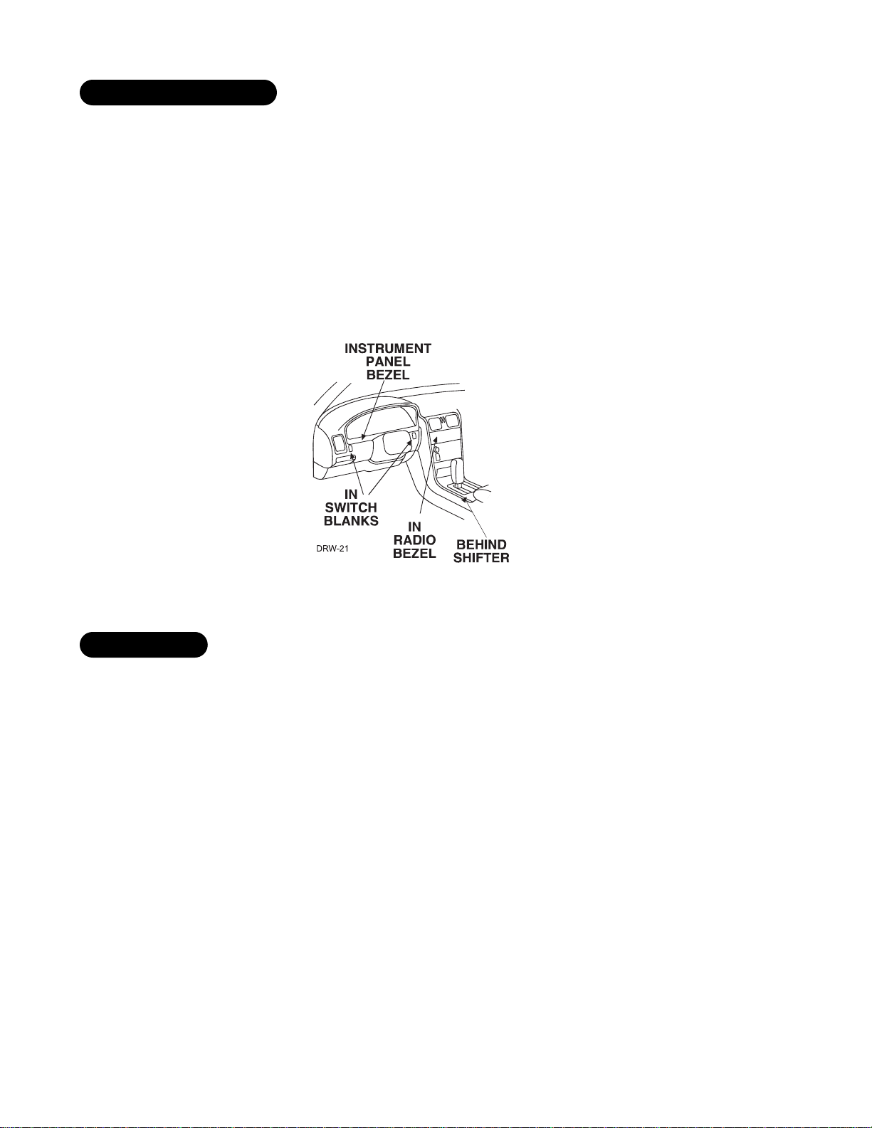
Things to remember when positioning the Status LED:
■ It should be visible from both sides and the rear of the vehicle, if possible.
■ It needs at least
1
/2-inch clearance to the rear.
■ It is easiest to use a small removable panel, such as a switch blank or a dash bezel. Remove it before drilling
your
9
/32-inch hole.
■ Use quick-disconnects near the LED wires if the panel is removable. This allows mechanics or other installers
to remove the panel without cutting the wires.
If the Failsafe
®
Starter Kill Relay or its connections are immediately visible upon removal of the underdash panel,
they can easily be bypassed. Always make the relay and its connections difficult to discern from the factory
wiring! Exposed yellow butt connectors do not look like factory parts, and will not fool anyone! For this reason,
routing the starter kill wires away from the steering column is recommended.
starter kill relay
locations for the status LED
Page 8
8 © 1999 Directed Electronics, Inc. Vista, CA
finding the wires you need
Now that you have decided where each component will be located, you’re going to find the wires in the car that
the security system will be connected to.
IMPORTANT! Do not use a 12V test light to find these wires! All testing described in this manual
is described using a digital multimeter.
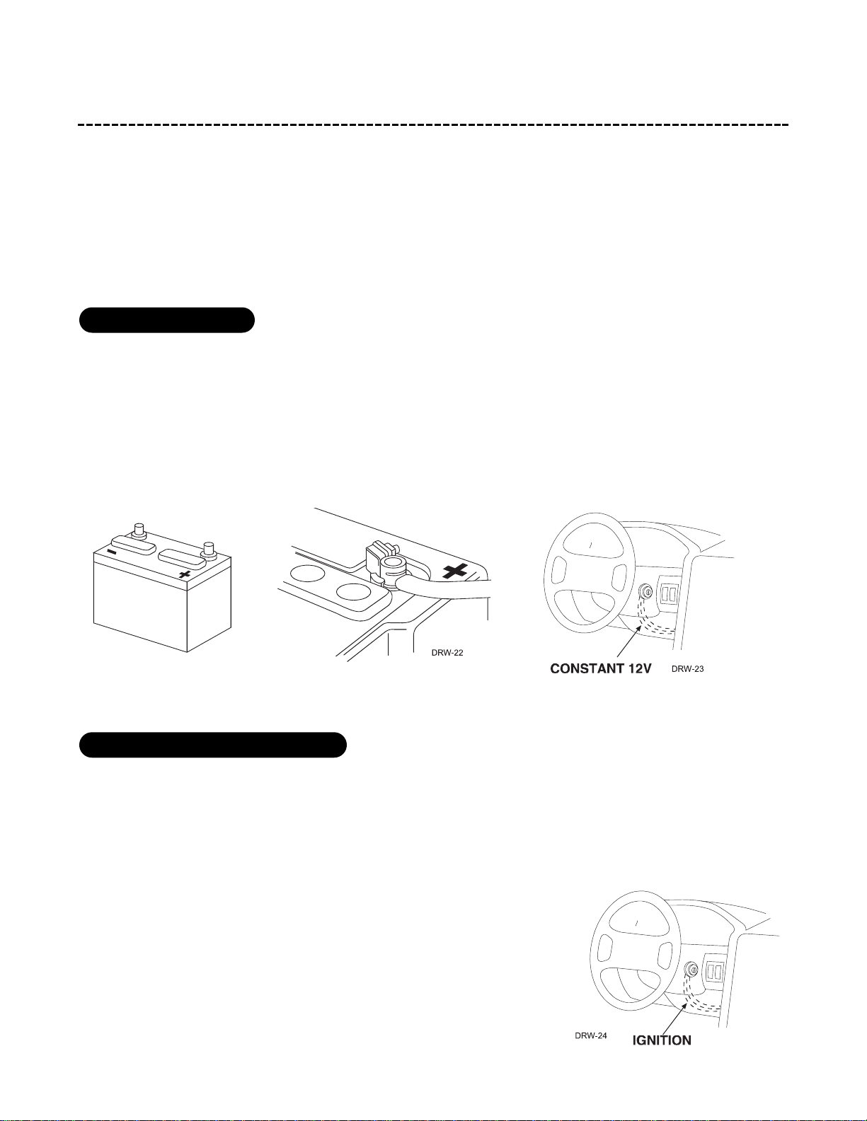
We recommend two possible sources for 12V constant: The (+) terminal of the battery, or the constant supply to
the ignition switch. Always install a fuse within 12 inches of this connection.
IMPORTANT! Do not remove the fuse holder on the red (H1/11) wire. It ensures that the control
module has its own fuse, of the proper value, regardless of how many accessories are added to the
main power feed.
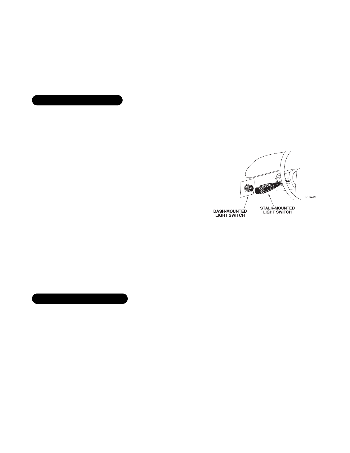
The ignition wire is powered when the key is in the run or start position. This is because the ignition wire powers
the ignition system (spark plugs, coil) as well as the fuel delivery system (fuel pump, fuel injection computer).
Accessory wires, on the other hand, lose power when the key is in the start position to make more current avail-
able to the starter motor.
How to find (+)12V ignition with your multimeter:
1. Set to DCV or DC voltage (12V or 20V is fine).
2. Attach the (-) probe of the meter to chassis ground.
3. Probe the wire you suspect of being the ignition wire. The steering
column harness or ignition switch harness is an excellent place to find
this wire.
finding the 12V switched ignition wire
obtaining constant 12V
Page 9
© 1999 Directed Electronics, Inc. Vista, CA 9
4. Turn the ignition key switch to the run position. If your meter reads (+)12V, go to the next step. If it doesn’t,
probe another wire.
5. Now turn the key to the start position. The meter display should stay steady, not dropping by more than a
few tenths of a volt. If it drops close to or all the way to zero, go back to step 3. If it stays steady at (+)12V,
you have found an ignition wire.
you have found an ignition wire.
The (+) parking light wire is often found near the switch. Many cars have the switch built into the turn signal
lever, and in these cars the parking light wire can be found in the steering column. The same wire is often avail-
able in the kick panel or running board.
How to find a (+) parking light flash wire with your multimeter:
1. Set to DCV or DC voltage (12V or 20V is fine).
2. Attach the (-) probe of the meter to chassis ground.
3. Probe the wire you suspect of being the parking light wire.
Usually, the area near the headlight/parking light switch is an
excellent area to start, as is the kick panel.
4. Turn on the parking lights. If your meter shows (+)12V, turn off
the parking lights and make sure it goes back to zero.
5. If it does return to zero, turn the parking lights back on and,
using the dash light dimmer control, turn the brightness of the
dash lights up and down. If the meter changes more than a volt
when using the dimmer, look for another wire. If it stays rela-
tively close to (+)12V, you have found your parking light wire.
The best places to find the door switch wire are:
■ At the pin switch: When testing at the pin switch, check the wire to ensure that it “sees” all the doors. Often,
the passenger switch will cover all the doors even if the driver’s switch will not.
■ At the dome light: This may not be your best choice if the vehicle has delayed domelight supervision, but it
will work in vehicles with completely diode-isolated pin switches.
Once you have determined the wire color, the easiest place to connect to the wire is often at the kick panel, at
the windshield pillar, or in the running board. When an easy location is not available, running a wire to the dome-
light itself is often the best solution.
finding the door pin switch circuit
finding a (+) parking light wire
Page 10

10 © 1999 Directed Electronics, Inc. Vista, CA
How to find a door pin switch trigger wire with your multimeter:
1. Set to DCV or DC voltage (12V or 20V is fine).
2. In most cars, fasten the (+) probe of your meter to (+)12V constant.
3. Probe the wire you suspect of being the door trigger wire. If the meter reads (+)12V when any door is opened,
you have found a trigger wire.
NOTE: Make sure the wire you use “sees” all the doors! Some newer GM vehicles lack standard-type
pin switches. The dome light in these vehicles is turned on when the door handle is lifted. These
usually have a blue/white or white wire coming out of the door into the kick panel which will
provide a (-) trigger for all doors. Some GM vehicles (some Cavaliers, Grand Ams, etc.) have a yellow
wire coming out of the door which provides a (+) door trigger.
How to find the (+)12V starter wire with your multimeter:
1. Set to DCV or DC voltage (12V or 20V is fine).
2. Attach the (-) probe of the meter to chassis ground.
3. Probe the wire you suspect of being the starter wire. The steering column
is an excellent place to find this wire. Remember you do not need to inter-
rupt the starter at the same point you test it. Hiding your starter kill relay
and connections is always recommended.
4. Turn the ignition key switch to the start position. Make sure the car is not
in gear! If your meter reads (+)12V, go to the next step. If it doesn’t, probe
another wire.
5. Cut the wire you suspect of being the starter wire.
6. Attempt to start the car. If the starter engages, reconnect it and go back
to step 3. If the starter does not turn over, you have the right wire.
finding a starter wire
Page 11
© 1999 Directed Electronics, Inc. Vista, CA 11
making your connections
When connecting the security system’s wires to the wires in the vehicle it is important that the connections are
tight and no bare wire is exposed. In this section, two types of connections are described that may be used to
connect the wires from the security system into the vehicle’s wiring. Both types of connections are electrically
acceptable if made correctly. Other types of "tap-in" connections, such as T-Taps are not acceptable.
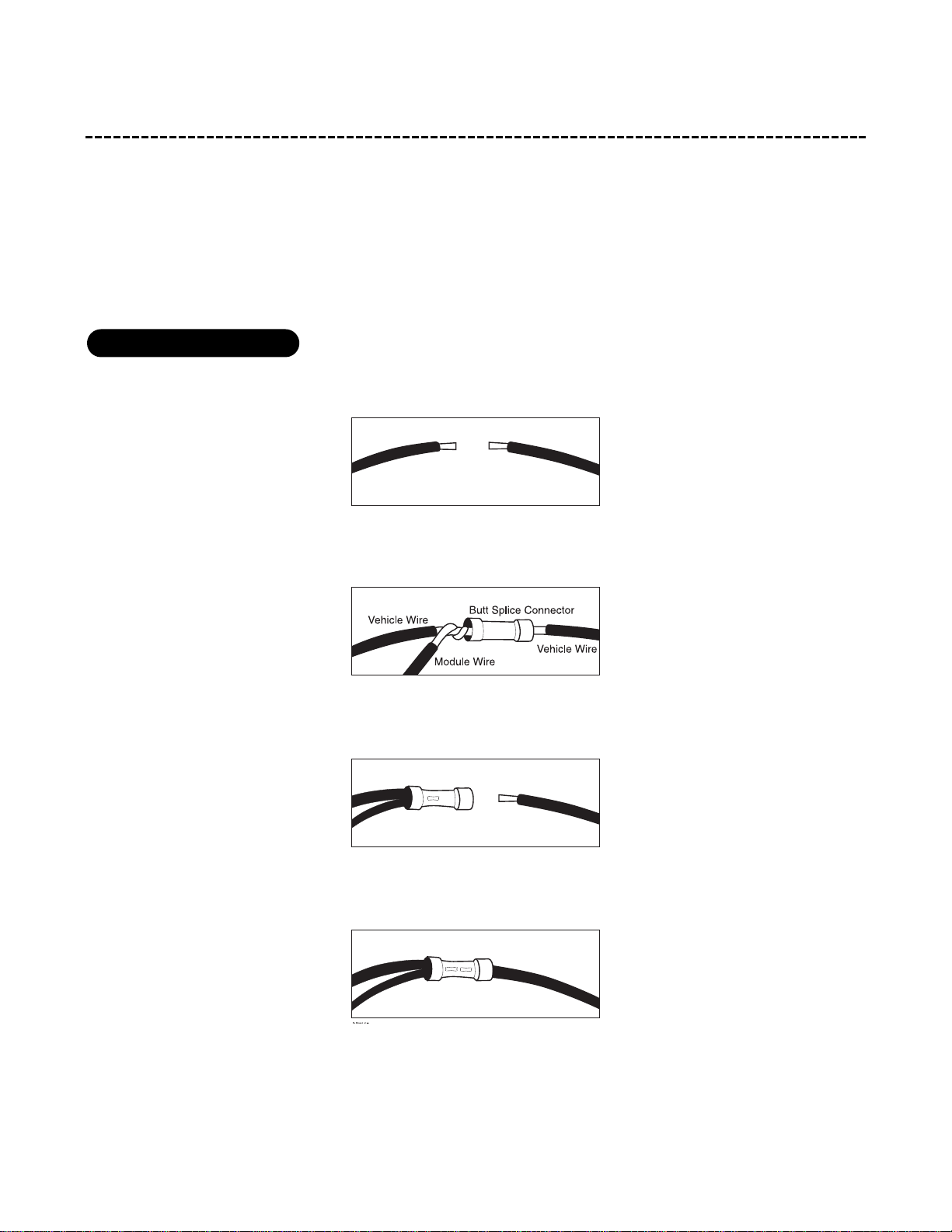
1. Cut the wire and strip back about
1
/4-inch of insulation on each end of the wire.
2. Twist one end of the vehicle’s wire with the security module’s wire.
3. Insert the twisted pair of wires into one end of the butt connector and crimp securely.
4. Insert the other end of the vehicle’s wire into the other end of the butt connector and crimp securely.
solderless butt connections
Cut and Strip Vehicle Wire
Vehicle Wire
Module Wire
Crimp
Vehicle Wire
Crimp
Page 12
12 © 1999 Directed Electronics, Inc. Vista, CA
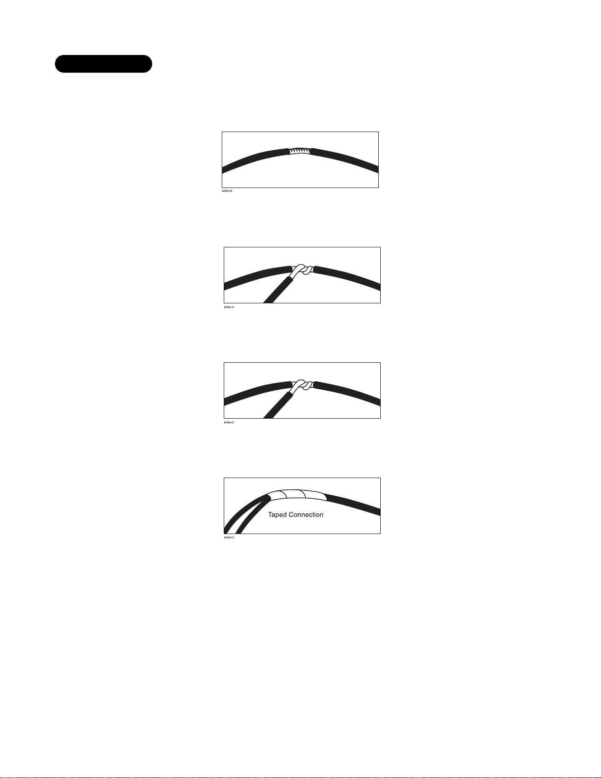
1. Using your wire strippers and razor knife, strip approximately 1/2-inch of insulation off the wire to be con-
nected to, without cutting the wire.
2. Twist the security module’s wire around the bare section of the vehicle’s wire.
3. Solder the bare connection thoroughly using rosin core solder.
4. Completely insulate the connection with electrical tape.
solder connections
Stripped Vehicle Wire
Vehicle Wire
Module Wire
Vehicle Wire
Module Wire
Page 13

© 1999 Directed Electronics, Inc. Vista, CA 13
primary harness (H1), 12-pin connector
______
______
______
______
______
______
______
______
______
______
______
______
RED/WHITE (-) 200MA CHANNEL 2 VALIDITY OUTPUT
RED (+) CONSTANT POWER INPUT
BROWN (+) SIREN OUTPUT
YELLOW (+) SWITCHED IGNITION INPUT, ZONE 5
BLACK (-) CHASSIS GROUND INPUT
VIOLET (+) DOOR TRIGGER INPUT, ZONE 3
BLUE (-) INSTANT TRIGGER INPUT, ZONE 1
GREEN (-) DOOR TRIGGER INPUT, ZONE 3
BLACK/WHITE (-) 200MA DOMELIGHT SUPERVISION OUTPUT
WHITE/BLUE (-) 200 MA CHANNEL 3 SELECTABLE OUTPUT
WHITE (+)/(-) SELECTABLE LIGHT FLASH OUTPUT
ORANGE (-) 500 MA ARMED OUTPUT
H1/1
H1/2
H1/3
H1/4
H1/5
H1/6
H1/7
H1/8
H1/9
H1/10
H1/11
H1/12
Page 14
14 © 1999 Directed Electronics, Inc. Vista, CA
primary harness wire connection guide
This guide describes in detail the connection of each wire. Also included are possible applications of each wire.
This system was designed with the ultimate in flexibility and security in mind. Many of the wires have more than
one possible function. Please read carefully to ensure a thorough understanding of this unit.
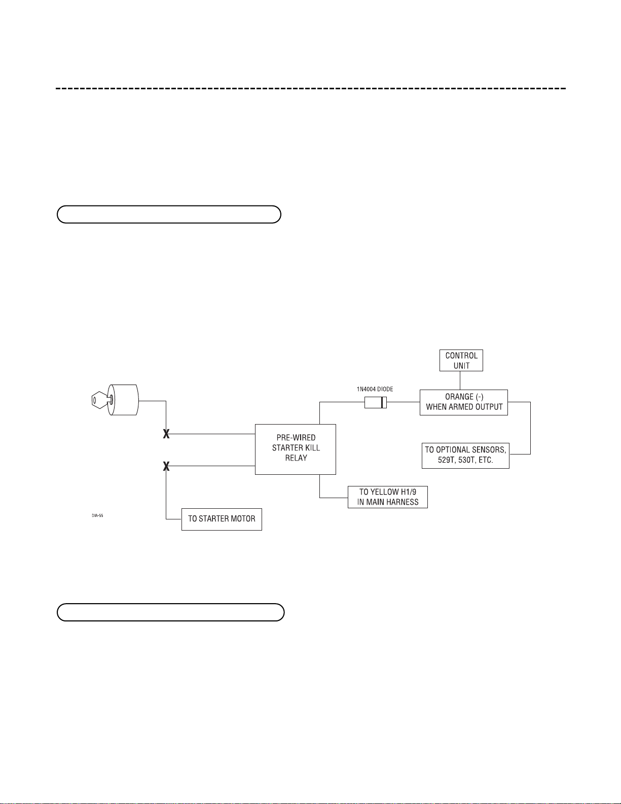
This wire supplies a (-) ground as long as the system is armed. This output ceases as soon as the system is dis-
armed. The orange wire is used to control the pre-wired starter kill relay. It can supply up to 500 mA of current.
NOTE: If connecting the orange wire to control another module, such as a 529T or 530T window
module, a 1 amp diode (type 1N4004) will be required (see below).
IMPORTANT! Never interrupt any wire other than the starter wire.
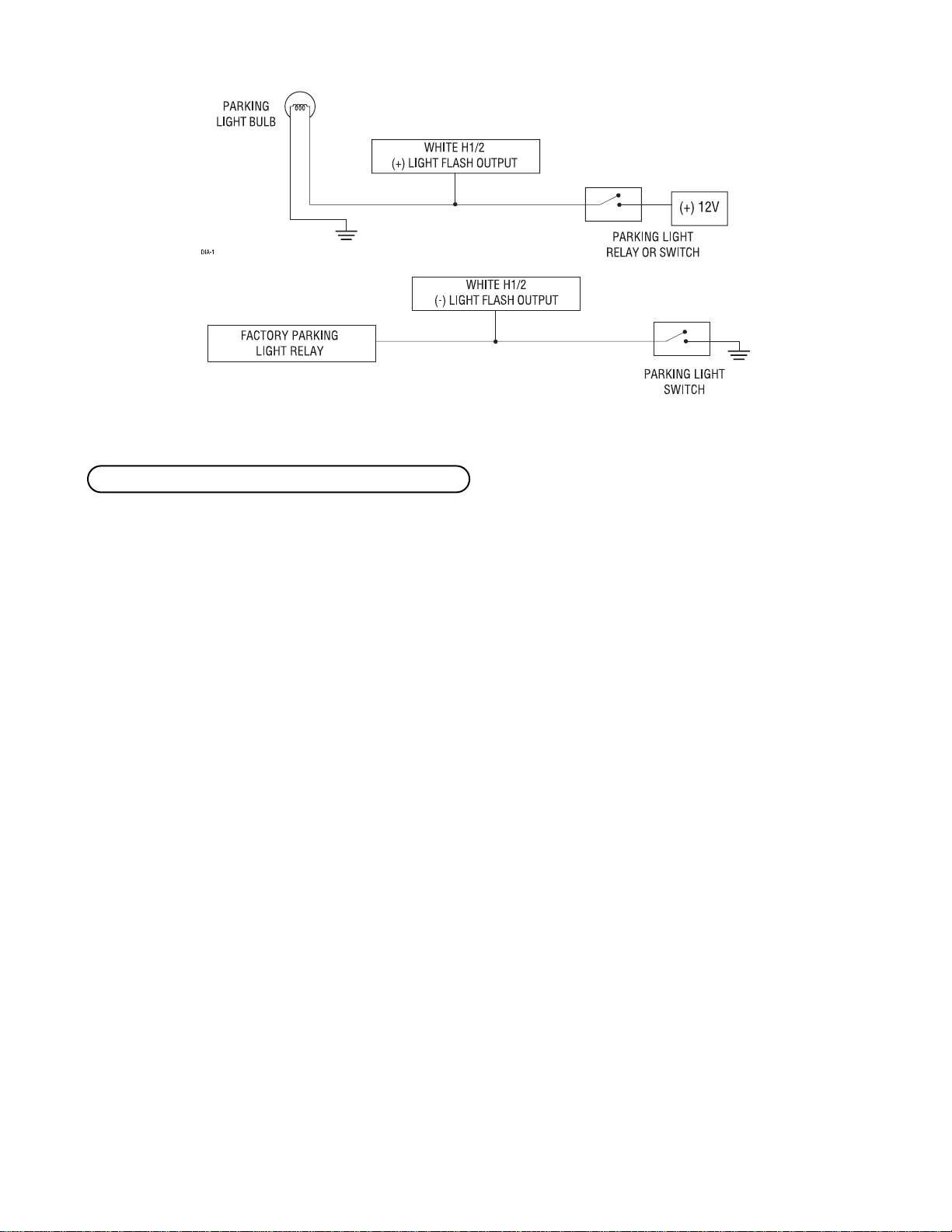
As shipped, this wire should be connected to the (+) parking light wire. If the light flash polarity jumper inside
the unit is moved to the opposite position (see Internal Programming Jumper section of this guide), this wire
supplies a (-) 200 mA output. This is suitable for driving (-) parking light wires.
See diagrams on the following page.
H1/2 WHITE (+/-) selectable light flash output
H1/1 ORANGE (-) ground-when-armed output
Page 15
© 1999 Directed Electronics, Inc. Vista, CA 15
This wire provides a 200 mA (-) output whenever the transmitter button(s) controlling channel three is pressed.
This output can be programmed to provide the following type of outputs (see System Features Learn Routine
section of this guide):
■ A validity output will send a signal as long as the transmission is received.
■ A latched output will send a signal continuously when channel three is pressed and will continue until
channel three is pressed again.
■ A latched/reset with ignition output works similar to the latched output, but will also reset (output will
stop) when the ignition is turned on then off.
■ A 30-second timed output will send a signal for 30 seconds when channel three is pressed. This output can
also be programmed to provide a second unlock pulse when the disarm button is pressed within 15 second
after disarming the system. This can be used to unlock the passenger doors when installing progressive door
locks.
■ A second unlock output will provide a second unlock pulse whenever the disarm button is pressed within 15
seconds after disarming the system. This setting could be used to unlock the passenger doors when installing
progressive door locks, for instance.
■ A delayed accessory output provides a 200mA (-) latched output three seconds after the ignition is turned
on. It will remain active when the key is turned off, until a door is opened and closed. This setting could be
used in conjunction with a relay to energize certain circuits in the vehicle that would normally require the
key to be turned on i.e. the radio, power windows, etc.
IMPORTANT! Never use this wire to drive anything but a relay or a low-current input! This
transistorized output can only supply (-)200 mA, and connecting directly to a solenoid, motor, or
other high-current device will cause the module to fail.
H1/3 WHITE/BLUE 200 mA (-) channel three output
Page 16

16 © 1999 Directed Electronics, Inc. Vista, CA
Connect this wire to the optional domelight supervision relay as shown below:
IMPORTANT! This output is only intended to drive a relay. It cannot be connected directly to the
domelight circuit, as the output cannot support the current draw of one or more bulbs.
Most vehicles use negative door trigger circuits. Connect the green wire to a wire which shows ground when any
door is opened. In vehicles with factory delays on the domelight circuit, there is usually a wire that is unaffected
by the delay circuitry.
This input will respond to a negative input with an instant trigger. It is ideal for hood and trunk pins and will
report on zone one.
H1/6 BLUE (-) instant trigger
H1/5 GREEN (-) door trigger input
H1/4 BLACK/WHITE 200 mA (-) domelight supervision output
Page 17
© 1999 Directed Electronics, Inc. Vista, CA 17
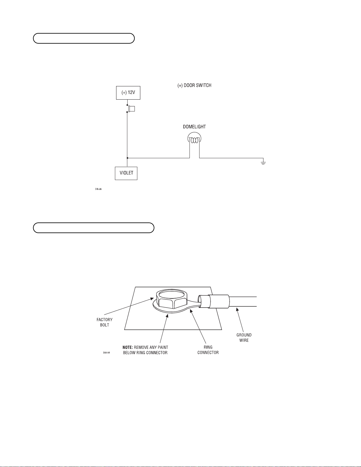
This wire is used in vehicles that have a positive (+) switched dome light circuit . Connect the violet wire to a
wire that shows (+)12V when any door is opened, and ground when the door is closed.
Connect this wire to bare metal, preferably with a factory bolt rather than your own screw. Screws tend to either
strip or loosen with time. All components, including the siren, should be grounded to the same point in the
vehicle if possible.
H1/8 BLACK (-) chassis ground connection
H1/7 VIOLET (+) door trigger input
Page 18
18 © 1999 Directed Electronics, Inc. Vista, CA
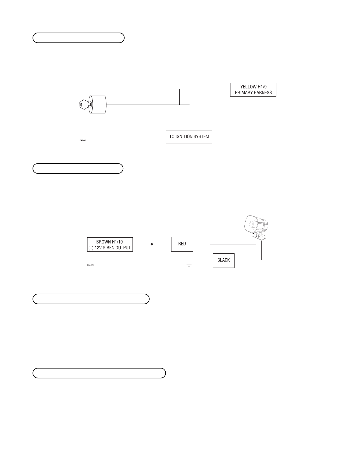
Connect this wire to the (+)12V ignition wire. This wire must show (+)12V with the key in Run position and during
cranking. Take care to insure that this wire cannot be shorted to the chassis at any point.
Connect this to the red wire of the siren. Connect the black wire of the siren to (-) chassis ground, preferably at
the same point you connect the control module’s black ground wire.
Before connecting this wire, remove the supplied fuse. Connect to the battery positive terminal or the constant 12V supply
to the ignition switch.
NOTE: Always use a fuse within 12 inches of the point you obtain (+)12V. Do not use the 15A fuse
in the harness for this purpose. This fuse protects the module itself.
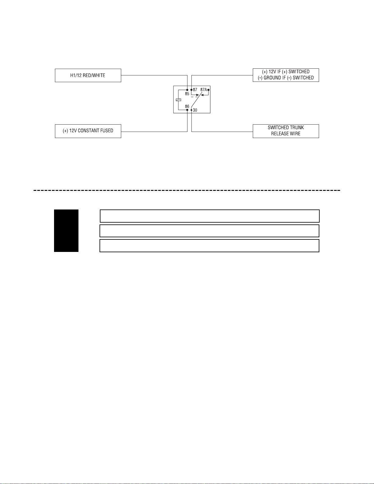
When the system receives the code controlling Channel Two for longer than 1.5 seconds, the red/white will supply
an output as long as the transmission continues. This is often used to operate a trunk/hatch release or other
relay/driven function.
H1/12 RED/WHITE 200 mA (-) channel 2 output
H1/11 RED (+) 12V constant power input
H1/10 BROWN (+) siren output
H1/9 YELLOW (+) ignition input
Page 19
© 1999 Directed Electronics, Inc. Vista, CA 19
IMPORTANT! Never use this wire to drive anything but a relay or a low-current input! The transistorized output can only supply 200 mA of current. Connecting directly to a solenoid, motor, or other
high-current device will cause it to fail.
harness 2 (H2), (+/-) door lock outputs
______
______
______
This system can control two common power door lock types without any additional parts! With certain vehicles,
or if an actuator is to be installed, either a 451M Door Lock Relay Satellite or two relays will be required.
IMPORTANT! If you mistake a Type C direct-wired system for a Type A positive-pulse system, the
module will be damaged!
BLUE (-) UNLOCK, (+) LOCK OUTPUT
EMPTY UNLESS USING 451M
GREEN (-) LOCK, (+) UNLOCK OUTPUT
H2/A
H2/B
H2/C
Page 20
20 © 1999 Directed Electronics, Inc. Vista, CA
door lock harness (H2) wire connection guide
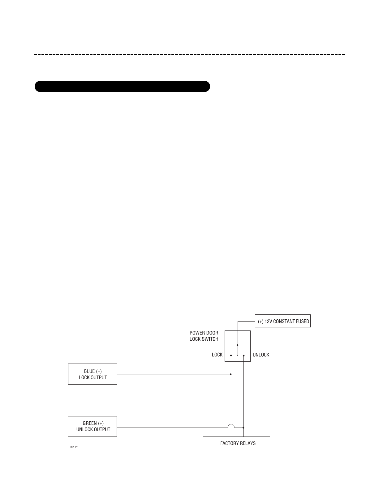
The system can control a Type A system directly, with no additional parts. The switch will have three wires on
it, and one will test (+)12V constantly. The others will alternately pulse (+)12V when the switch is pressed to
the lock or unlock position.
If you cannot get to the switch, and you find a set of wires that pulse (+)12V alternately on lock and unlock,
you must take care to ensure that it is not a Type C direct-wire system.
Here is a test: Cut the wire which pulses (+)12V on lock, and then operate the switch to unlock. If all doors
unlock, the vehicle uses type A system. If you lose all door lock operation in both directions, you are operating
the master switch in a Type C system.
If you lose all door lock operation of one or more doors, but not all motors stop operating, and other doors still
work, you have cut a wire leading directly to one or more motors. You must instead find the actual wires leading
to the switch.
Many domestically-made GM vehicles use Type A locks. However, many more GM vehicles are Type C than in pre-
vious years. The full-size pickups (1989-up), many of the S10 Blazers, the Corvette, 1995 Cavalier/Sunfire 1993
and newer, Camaro/Firebird all use Type C door locks, and cannot be controlled without a 451M! Almost all domes-
tically-built Fords are Type C. Ford builds very few Type A systems. Chrysler builds both Type A and Type C, so
use caution.
type A: (+) 12V pulses from the switch to the factory relays
Page 21
© 1999 Directed Electronics, Inc. Vista, CA 21
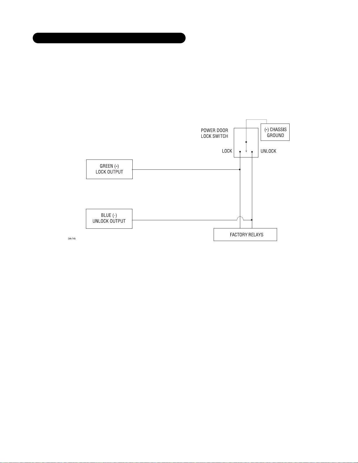
This system is common in many Toyota, Nissan, Honda, and Saturn models, as well as Fords with the keyless-
entry system (some other Fords also use Type B).
The switch will have three wires on it, and one wire will test ground all the time. One wire will pulse (-) when
the switch locks the doors, and the other wire will pulse (-) when the switch unlocks the doors. This type of
system is difficult to mistake for any other type.
type B: (-) pulses from the switch to the factory relays
Page 22
22 © 1999 Directed Electronics, Inc. Vista, CA
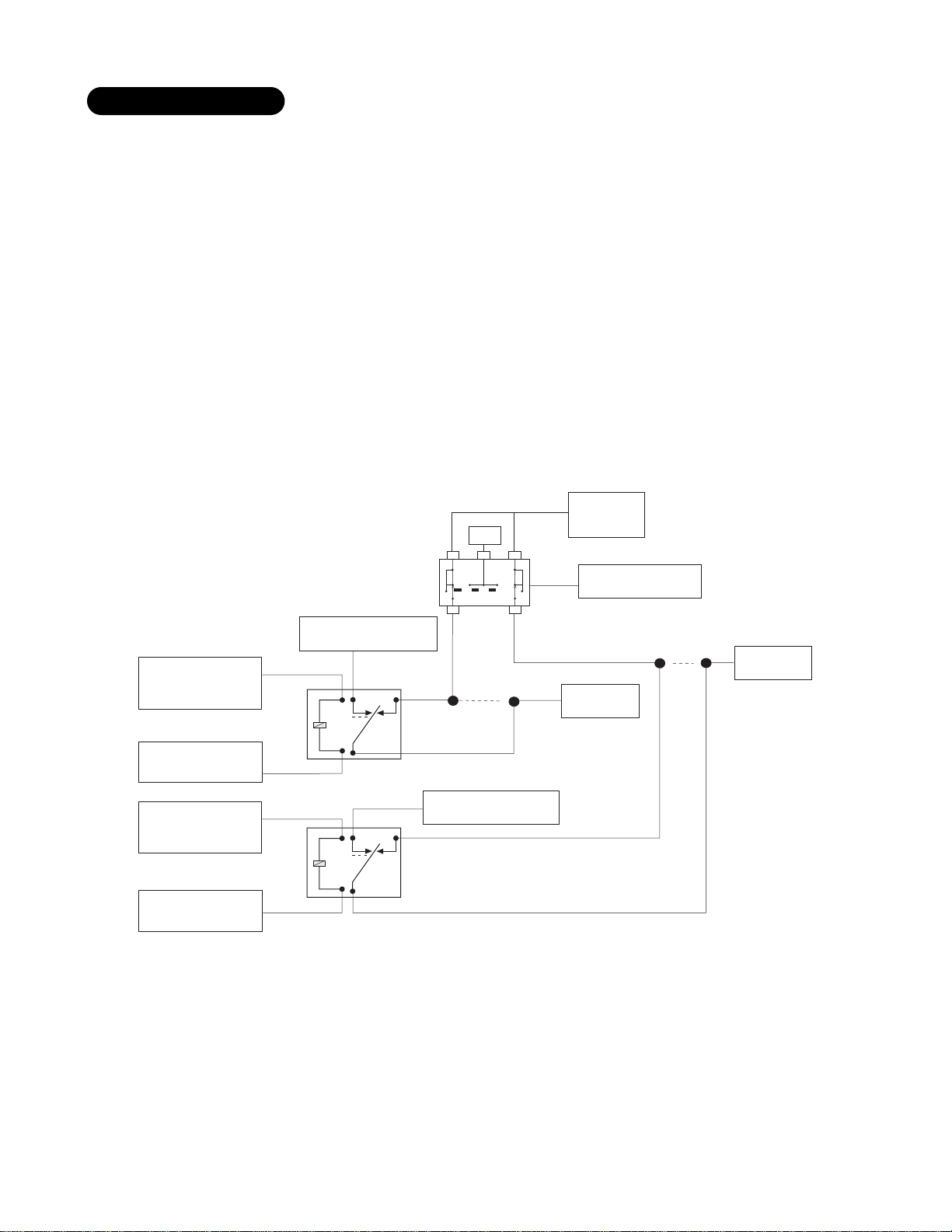
Interfacing with a reversing polarity system requires either two relays or one 451M (not included).
It is critical to identify the proper wires and locate the master switch to interface properly. Locate wires that
show voltage on lock and unlock. Cut one of the suspect wires and check operation of the locks from both
switches. If one switch loses operation in both directions and the other switch operates in one direction only,
you have located one of the target wires. The switch that lost all operation is the master switch. If one switch
works both directions and the other switch works only one direction, you have a Type A system. If both switches
still operate, but one or more doors have stopped responding entirely, you have cut a motor lead. Reconnect it
and continue to test for another wire. Once both wires have been located and the master switch identified, cut
both wires and interface as shown below.
IMPORTANT! If these are not connected properly, you will send (+) 12 volts directly to (-) ground,
possibly damaging the alarm or the factory switch.
type C: reversing polarity
(-) CHASSIS
(+) 12V
LOCK UNLOCK
GROUND
H 2/A GREEN (-)
LOCK WIRE
(+) 12V
CONSTANT FUSED
H 2/C BLUE (-)
UNLOCK WIRE
(+) 12V
CONSTANT FUSED
DIA-27
(+) 12V CONSTANT FUSED
87
87A
85
86
30
87
87A
85
86
30
XX
CUT
(+) 12V CONSTANT FUSED
MASTER SWITCH
MOTOR (+)
LOCK WIRE
CUT
XX
MOTOR (+)
LOCK WIRE
Page 23
© 1999 Directed Electronics, Inc. Vista, CA 23
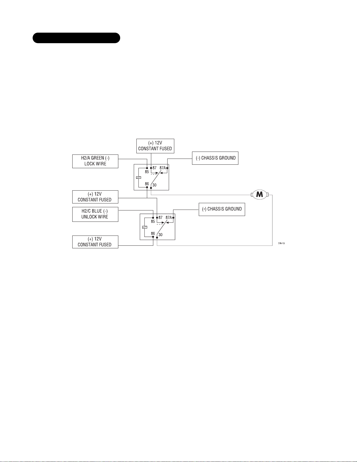
In order for this system to control one or more after-market actuators, a 451M or two relays (optional) are
needed.
Vehicles without factory power door locks require the installation of one actuator per door. This requires
mounting the door lock actuator inside the door. Other vehicles may only require one actuator installed in the
driver's door if all door locks are operated when the driver's lock is used. This type of installation is required to
operate factory lock systems in Volvo (except 850), SAAB, and most Mazda, Isuzu and Subaru models. The fuse
used on 12-volt inputs should be 7.5A per motor installed in the vehicle.
type D: after-market actuators
Page 24
24 © 1999 Directed Electronics, Inc. Vista, CA
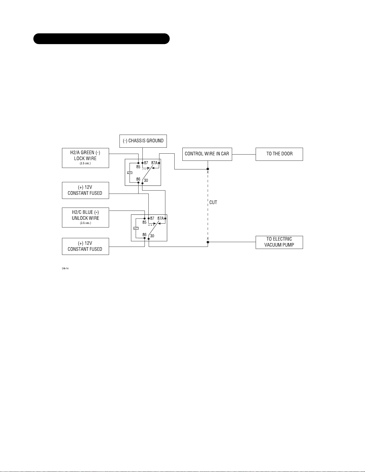
Door locks are controlled by an electrically activated vacuum pump. Some Mercedes and Audi models use a Type
D system. Test by locking doors from the passenger key cylinder. If all the doors lock, the vehicle's door lock
system can be controlled with just two relays (optional). The control wire can be found in either kick panel and
will show (+)12V when doors are unlocked and (-) ground when doors are locked.
To interface, see diagram below. The system must be programmed for 3.5 second door lock pulses. (See
System Features Learn Routine section of this guide.)
type E: mercedes-benz and audi (1985 & newer)
Page 25
© 1999 Directed Electronics, Inc. Vista, CA 25
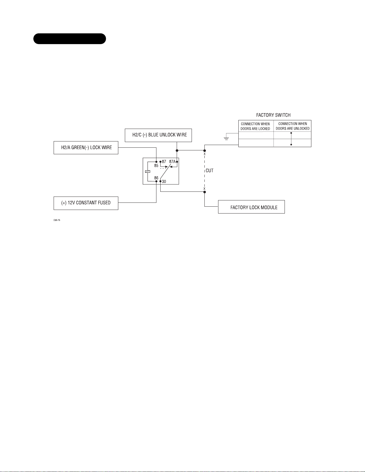
This system usually requires a negative pulse to unlock, and cutting the wire to lock the door. In some vehicles,
these are reversed. It is found in late-model Nissan Sentras, some Nissan 240SX, and Nissan 300ZX 1992-up. It
is also found in some Mazda MPV's and some Mitsubishi's.
One relay (optional) is used to interface to this type of system as follows:
type F: one-wire system
Page 26
26 © 1999 Directed Electronics, Inc. Vista, CA
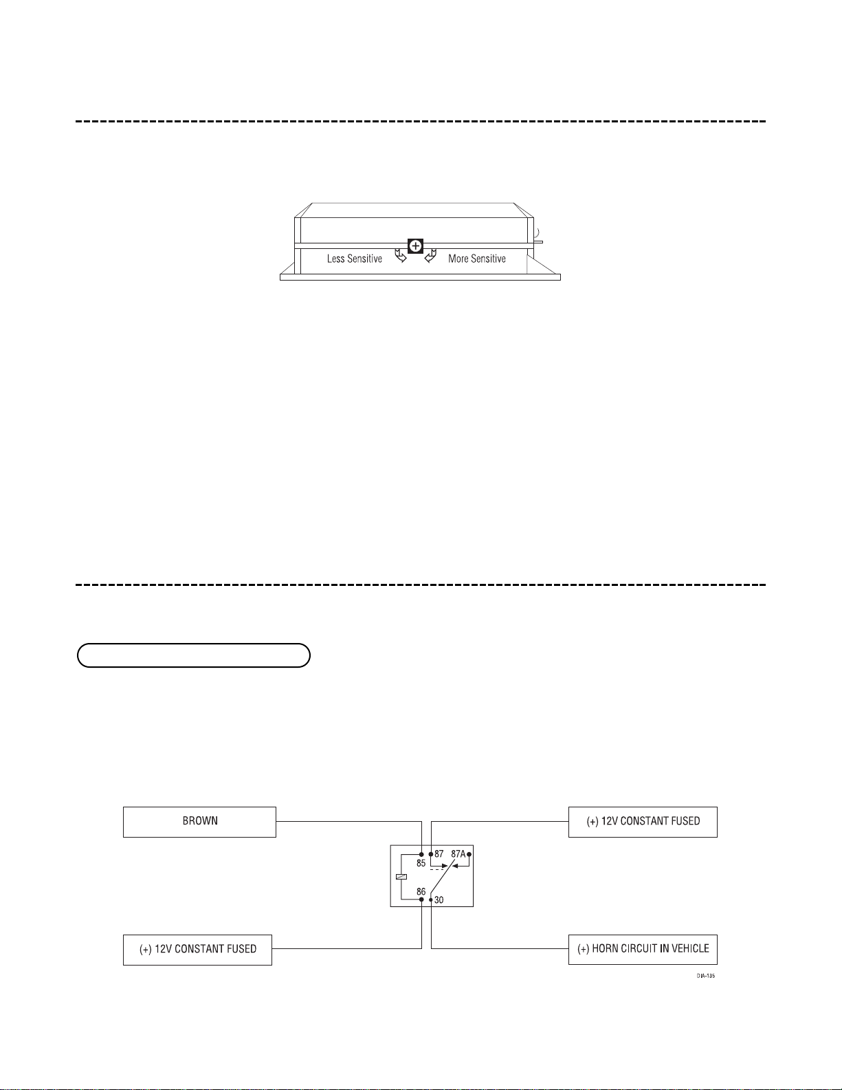
on-board doubleguard shock sensor
There is a Doubleguard®shock sensor inside the control unit. Adjustments are made via the rotary control as indi-
cated above. Since the shock sensor does not work well when mounted firmly to metal, we recommend against
screwing down the control module. The full trigger of the on-board shock sensor reports zone 2. (See Table of
Zones section of this guide.)
NOTE: When adjusting the sensor, it must be in the same mounting location that it will be after
the install is completed. Adjusting the sensor and then relocating the module requires readjustment.
auxiliary harness (H3), 2-pin connector
This wire supplies a 200 mA (-) output that can be used to honk the vehicle’s horn. It provides a pulsed output
when the security system is in the triggered sequence or in panic mode. In most vehicles with (-) horn circuits
this wire can control the vehicle’s horn without adding a relay. If the vehicle has a (+) horn circuit, an optional
relay must be used to interface with the horn circuit.
H3/1 BROWN (-) horn honk output
Page 27

© 1999 Directed Electronics, Inc. Vista, CA 27
This wire supplies a 200mA (-) output whenever the button(s) controlling Channel Four is pressed and will con-
tinue until the button(s) is released. This output can be used to control optional accessories.
IMPORTANT! Never use this wire to drive anything but a relay or a low-current input! This
transistorized output can only supply 200 mA (-), and connecting directly to a solenoid, motor, or
other high-current device will cause the module to fail.
plug-in harnesses
The super bright LED operates at 2V DC. Make sure the LED wires are not shorted to ground as the LED will be
damaged. The LED fits into a
9
/32-inch mounting hole. Be sure to check for clearance prior to drilling the mount-
ing hole.
The Valet
®
/Program switch should be accessible from the driver’s seat. It plugs into the blue port on the side of
the unit. Since the system features Valet
®
by remote, the switch can be well hidden. Consider what the switch
will be used for before choosing a mounting location. Check for rear clearance before drilling a
9
/32-inch hole and
mounting the switch.The GRAY wire in the two-pin plug may also be used as a (+) Ghost switch
™
input and can
be connected to any (+) switch in the vehicle. (See Feature Descriptions section of this guide.)
NOTE: Please note for the customer the location of the Valet
®
/Program switch in the section pro-
vided in the Owner’s Guide.
The black three-pin port can be used for programming the unit or to accommodate a serial controller. When using
the optional DEI Bitwriter
™
or PC Interface module (DEI part number 996T) for programming, it is possible to con-
figure any or all of the programmable functions using an IBM-compatible personal computer. When using a serial
controller, such as DEI’s 103T Keypad or the DEI 400A Car★Com, basic operating functions can be controlled
without the use of a remote transmitter. For more information please refer to the guides packaged with these DEI
compatible products.
data input port, 3-pin black port
valet/program switch, 2-pin blue plug
super-bright LED, 2-pin white plug
H3/2 VIOLET/BLACK (-) 200 mA channel 4 output
Page 28
28 © 1999 Directed Electronics, Inc. Vista, CA
four-pin optional sensor harness
The red wire supplies constant power to the optional sensor.
The black wire supplies ground to the optional sensor.
The blue and green wires are multiplex inputs. They are both tied to the same zone. If an input of less than 0.8
seconds is supplied to either wire the Warn-Away
®
response will occur. An input longer than 0.8 seconds to either
wire will initiate the triggered sequence and report zone 4.
internal programming jumper
This jumper is used to determine the light flash output. In the (+) position, the on-board relay is enabled and
the unit will output (+)12V on the WHITE wire, H1/2. In the (-) position, the on-board relay is disabled. The
WHITE wire, H1/2, will supply a 200 mA (-) output suitable for driving factory parking light relays. To access this
jumper, you must open the control module.
light flash jumper
BLUE, GREEN wires
BLACK wire
RED wire
Page 29
© 1999 Directed Electronics, Inc. Vista, CA 29
system features learn routine
The System Features Learn Routine dictates how the unit operates. It is possible to access and change any of the
feature settings using the Valet
®
/Program switch. However, this process can be greatly simplified by using the
optional Personal Computer Interface, or DEI
®
Bitwriter™. Any of the settings can be changed and then assigned
to a particular transmitter, up to four, a feature called Owner Recognition. Each time that particular transmitter
is used to disarm the system, the assigned feature settings will be recalled. Owner Recognition is only possible
when programming the unit via the computer interface or DEI
®
Bitwriter™. If programming with the PC interface
or the DEI
®
Bitwriter™, the learn routine can be locked or unlocked. If it is locked no features can be changed.
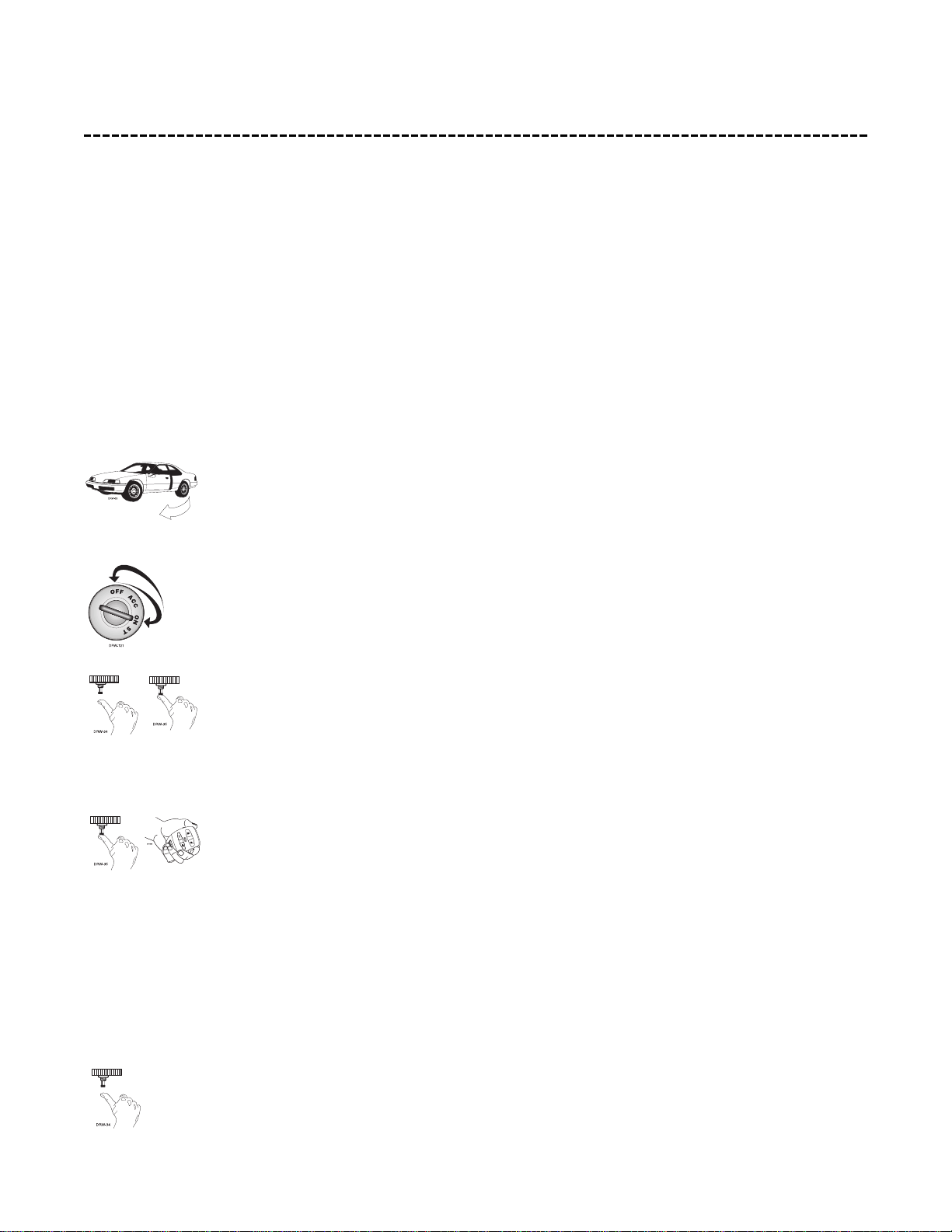
To enter the System Features Learn Routine:
1. Open a door: The GREEN wire, H1/5, or the VIOLET, H1/7 must be connected.
2. Turn the ignition on, then off: The YELLOW wire, H1/9 must be connected.
3. Select a feature: Press and release the Valet
®
/Program button the number of times corre-
sponding to the step you wish to change. For example, to access the third feature, press
and release three times. Then press the button once more and HOLD it. The siren will chirp
the number of times equal to the step you have accessed.
4. Program the feature: While holding the Valet
®
/Program button, you can toggle the feature
on and off using the remote transmitter. Pressing the arm button will select the one chirp
or default setting. Pressing the button that is assigned to Channel Two (or the disarm only
button on an OEM configuration transmitter, see Transmitter/Receiver Learn Routine section
of this guide), will select the two chirp setting.
NOTE: The Valet
®
pulse count feature (8) and the Channel three timed output (9) have five possible settings each. Pressing the Channel Two (or disarm only) button will toggle through all the
possible settings.
5. Release the Valet
®
/Program button.
Page 30
30 © 1999 Directed Electronics, Inc. Vista, CA
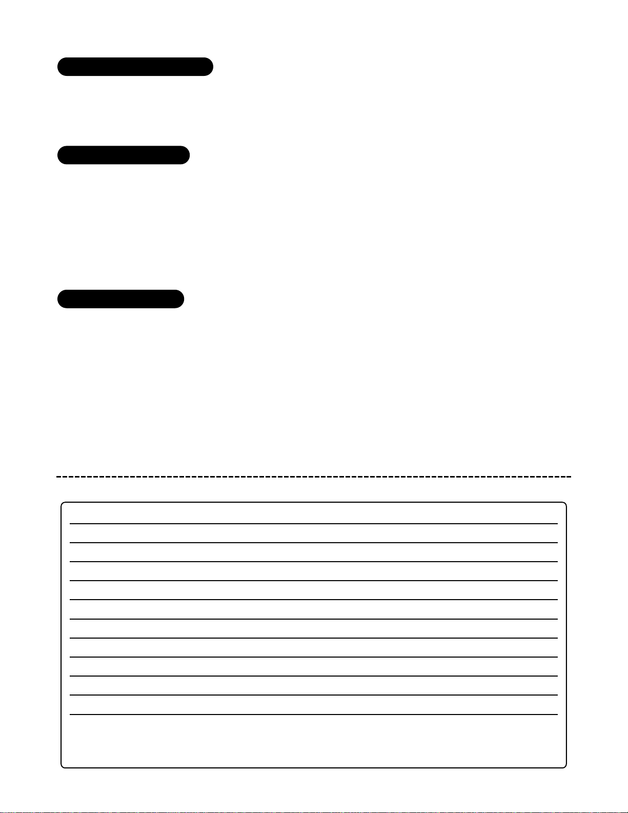
■ Other features can be programmed.
■ The Learn Routine can be exited if programming is complete.
Press and release the Valet
®
/Program button the number of times necessary to advance from the feature you just
programmed to the next one you want to program. Then press the Valet
®
/Program button once more and hold it.
For example, if you just programmed the third feature and you would like to program the seventh feature in the
menu, you would: Press and release the Valet
®
/Program button four times. Then press the Valet®/Program button
once more and hold it. The siren would chirp seven times to confirm access to the seventh feature.
The learn routine will be exited if any of the following occurs:
1. Close the open door.
2. Turn the ignition on.
3. No activity for longer than 15 seconds.
4. Press the Valet
®
/program button too many times.
system features menu
FEATURE NUMBER ONE-CHIRP SETTING (DEFAULT) TWO-CHIRP SETTING
1 Active arming Passive Arming
2 Audible arm/disarm confirmation on Audible arm/disarm confirmation off
3 Ignition-controlled locking on Ignition-controlled locking off
4 Ignition-controlled unlocking on Ignition-controlled unlocking off
5 Active locking Passive locking
6 0.8 second door lock pulses 3.5 second door lock pulses
7 Single unlock pulse Double unlock pulse
8 Door trigger error chirp on Door trigger error chirp off
9 Ignition-controlled domelight on Ignition-controlled domelight off
10 Valet switch input: 1 pulse Valet switch input: 2-5 pulses
11 Channel 3: validity Channel 3: latched/latched, reset with
ignition/30-second timed/second
unlock/delayed accessory output
to exit the learn routine
to access another feature
once a feature is programmed
Page 31

© 1999 Directed Electronics, Inc. Vista, CA 31
feature descriptions
1 ACTIVE/PASSIVE ARMING: When active arming is selected, the system will only arm when the transmitter is
used. When set to passive, the system will arm automatically 30 seconds after the last door is closed. To alert
the consumer of passive arming, the siren will chirp 20 seconds after the door is closed. This provides the con-
sumer with an audible warning prior to the system actually arming. At the 30 second mark, the system will arm
but the siren will not chirp.
2 AUDIBLE ARM/DISARM CONFIRMATION ON/OFF: This feature controls the chirps that confirm the arming and
disarming of the system. In the ON setting (default) the siren will provide audible confirmation when arming and
disarming the system. If programmed to the OFF position no siren chirps will be heard when arming and disarm-
ing.
3 IGNITION-CONTROLLED LOCKING ON/OFF: When turned on, the vehicle doors will lock three seconds after the
ignition is turned on.
4 IGNITION-CONTROLLED UNLOCKING ON/OFF: When turned on, the vehicle doors will unlock when the igni-
tion is turned off.
5 ACTIVE/PASSIVE LOCKING: If passive arming is selected in step 1, then the system can be programmed to
either lock the doors when passive arming occurs, or only lock the doors when the system is armed via the trans-
mitter. Active locking means the system will not lock the doors when it passively arms. Passive locking means
that the system will lock the doors when it passively arms.
NOTE: Remember, when passive arming is selected, the unit will chirp 20 seconds after the last door
is closed. The system does not actually arm or lock the doors until 30 seconds after the door has
been closed.
6 DOOR LOCK PULSE DURATION: Some vehicles require longer lock and unlock pulses to operate the door lock
vacuum pump. Programming the system to provide 3.5 second pulses, will accommodate the door lock interface
in these vehicles. The default setting is 0.8 second door lock pulses.
7 DOUBLE PULSE UNLOCK ON/OFF: Some vehicles require two pulses on a single wire to unlock the doors. When
the double pulse unlock feature is turned on, the unlock relay will provide two pulses instead of a single pulse.
8 DOOR TRIGGER ERROR CHIRP ON/OFF: With the door trigger error chirp programmed off, the system will not
report an invalid zone on arming when the door trigger wire is active. This eliminates the extra chirps that occur
when interfacing with vehicles that have exceptionally long dome light delay circuits.
9 IGNITION-CONTROLLED DOMELIGHT ON/OFF: If turned on, the system will turn on the domelight for 60
seconds when the ignition is turned off. The H1/4 BLACK/WHITE domelight supervision output must be connected
as described in the Primary Harness Wire Connection Guide section of this manual in order to control this feature.
Page 32
32 © 1999 Directed Electronics, Inc. Vista, CA
10 VALET®PULSE COUNT 1-5 PULSES: The system can be programmed to count the number presses of the Valet
®
switch before disarming the security system. The factory default setting is one pulse. The unit can be set for 2
to 5 pulses using the Channel Two button (or disarm only button on an OEM transmitter) to select the setting.
Ghost Switch
™
Option: For added security, the GRAY wire on the two-pin Valet®/Program button can
be connected to any switch in the vehicle that provides a positive (+) momentary pulse.
11 CHANNEL 3 VALIDITY/LATCHED/LATCHED RESET WITH IGNITION/30 SECOND TIMED/SECOND UNLOCK
OUTPUT/DELAYED ACCESSORY OUTPUT: Channel 3 can be programmed for these output configurations. The unit
is set to the default validity output. To change the configuration, use the disarm (or channel 2) button to toggle
to the different settings.
transmitter/receiver learn routine
The system comes with two transmitters that have been taught to the receiver. The receiver can store up to 4
different transmitter codes in memory. Use the following learn routine to add transmitters to the system or to
change button assignments if desired. The transmitter learn routine can be locked using the optional PC inter-
face or DEI
®
Bitwriter™. If the learn routine is locked no transmitters can be programmed to the system.
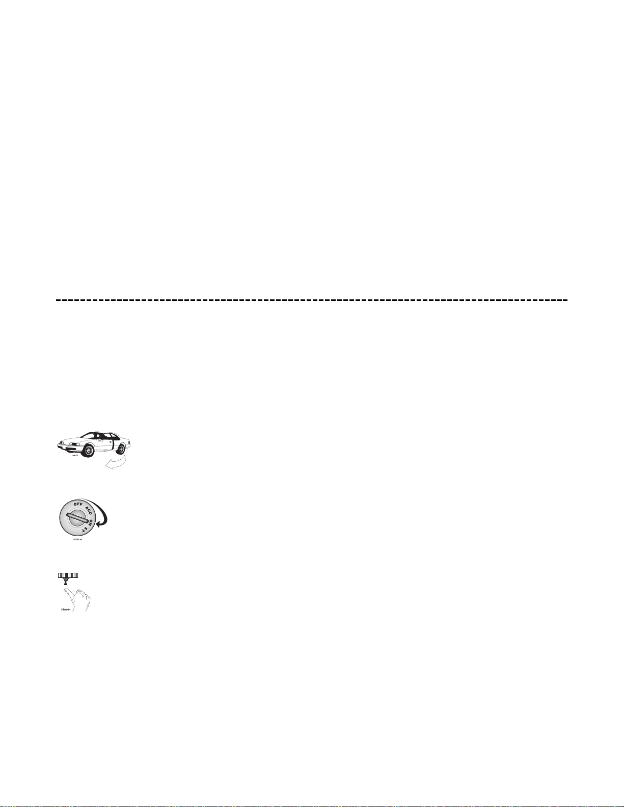
1. Open a door: The GREEN wire, H1/5, or the VIOLET, H1/7 must be connected.
2. Turn the ignition on: The YELLOW wire, H1/9 must be connected.
3. Select the receiver channel: Press and release the Valet
®
/Program button the number of
times necessary to access the desired channel. Press and hold the Valet
®
/Program button
once more. The siren will chirp and the LED will blink the number of times corresponding
to the channel that is accessed.
Page 33
© 1999 Directed Electronics, Inc. Vista, CA 33
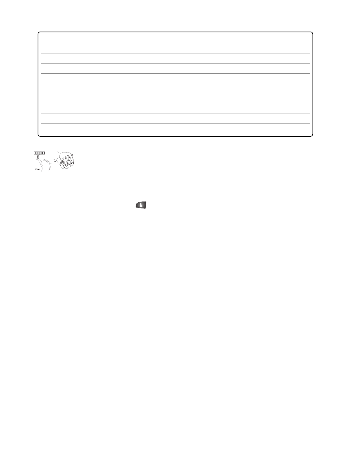
4. Press the transmitter button: While holding the Valet®/Program button, press the button
from the transmitter that you wish to assign to that channel. The unit will chirp indicat-
ing successful programming. It is not possible to teach a transmitter button to the system
more than once.
Channel 1 AUTO-LEARN: Programming to Channel One will automatically configure the channels in the
standard configuration. (Refer to owner’s guide, standard configuration)
Channel 2: If any transmitter button from a known transmitter is programmed to Channel Two, all transmitters
will be erased from memory, and system features will return to factory default settings. This is useful in cases
where one of the customer’s transmitters is lost or stolen. This will erase any lost or stolen transmitters from the
system’s memory. It can also be used to start from scratch if the transmitter buttons were programmed incor-
rectly.
Channel 7-9: To configure the system’s remote transmitters for OEM mode, Channels Seven through Nine are used
to assign the arm, disarm, and panic functions to separate buttons on the remote control. If the remote trans-
mitter being used has already been programmed to the system it will be necessary to delete all transmitters (see
Channel Two) before that transmitter can be programmed to Channels Seven through Nine.
CHANNEL NUMBER FUNCTION WIRE COLOR
1 Auto learn
2 Delete all transmitters
3 Arm/Disarm/Panic
4 Channel Two Red/White
5 Channel Three White/Blue
6 Channel Four Violet/Black
7 Arm
8 Disarm
9 Panic
Page 34
34 © 1999 Directed Electronics, Inc. Vista, CA
table of zones
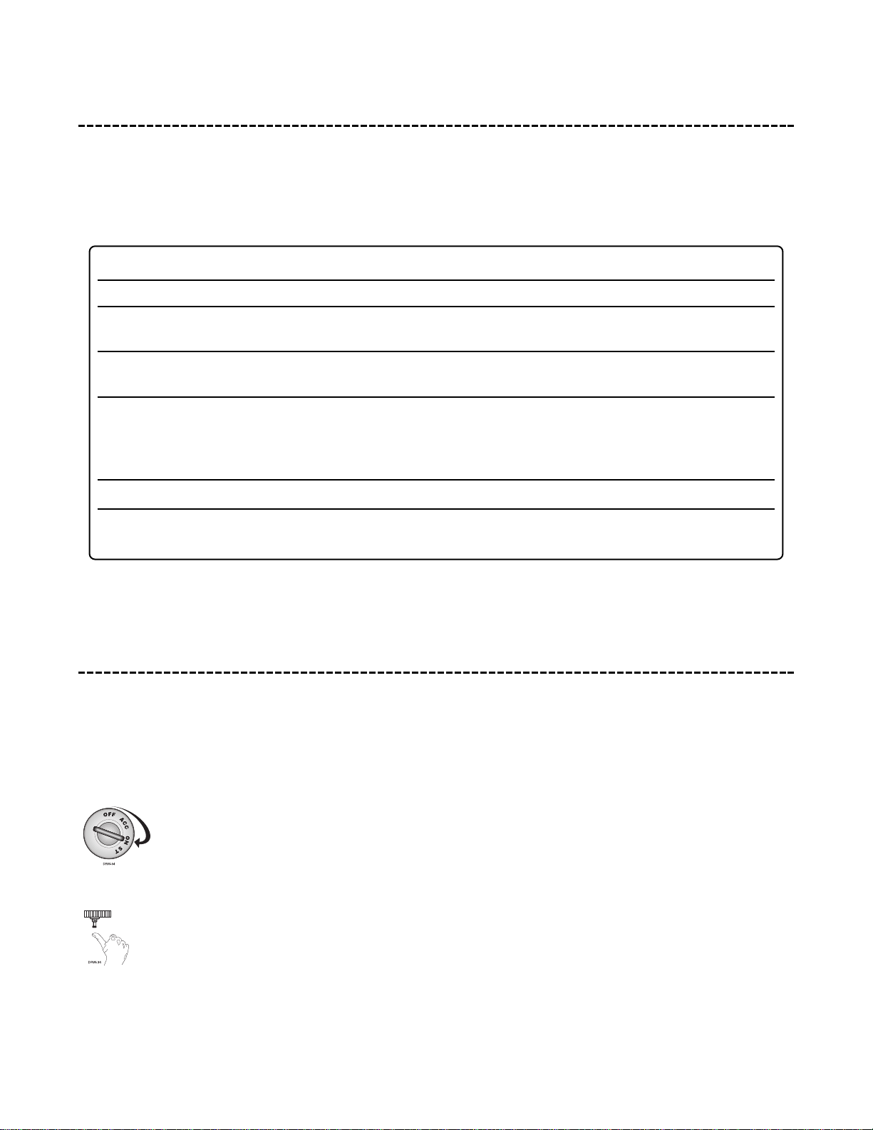
When using the diagnostic functions, use the Table of Zones to see which input has triggered the system. It is
also helpful in deciding which input to use when connecting optional sensors and switches.
long-term event history
The system stores the last two full triggers in memory. These are not erasable. Each time the unit sees a full
trigger, the older of the two triggers in memory will be replaced by the new trigger. To access long-term event
history:
1. Turn on the ignition.
2. Press and hold the Valet
®
/program switch.
The LED will flash in groups indicating the last two zones that triggered the unit.
NOTE: The Warn Away
®
triggers are not stored to memory.
Zone Number Trigger Type Input Description
One Instant H1/6 BLUE wire. Connect to optional hood/trunk pins
Two Multiplexed Heavy impact detected by the on-board Doubleguard
®
shock sensor.
Three Two-stage, progresses from Door switch circuit. H1/5 GREEN or H1/7 VIOLET.
warning to full alarm
Four Multiplex BLUE and GREEN wires of optional sensor plug. Inputs
shorter than 0.8 seconds will trigger a Warn Away
®
response, while inputs longer than 0.8 seconds will
instantly trigger full alarm sequence.
Five Two-stage (similar to doors) Ignition input. H1/9 YELLOW.
NOTE: The Warn Away
®
response does not report on the LED.
Page 35

© 1999 Directed Electronics, Inc. Vista, CA 35
rapid resume logic
This DEI®system will store its current state to non-volatile memory. If power is lost and then reconnected the
system will recall the stored state from memory. This means if the unit is in Valet
®
mode and the battery is dis-
connected for any reason, such as servicing the car, when the battery is reconnected the unit will still be in Valet
®
mode. This applies to all states of the system including arm, disarm, and Valet®mode.
troubleshooting
■ Starter kill doesn’t work:
Is the correct starter wire being interrupted? If the car starts when the starter kill relay is completely discon-
nected, the wrong starter wire has been cut and interrupted. Yellow (H1/9) wire is not connected to true ignition.
It is connected to an accessory circuit.
■ Shock sensor doesn’t trigger the alarm:
Has Nuisance Prevention
®
Circuitry been triggered? If so, you will hear five chirps when disarming. To check this,
turn the ignition key on and off to clear NPC
™
from memory, and then retest the shock sensor. For a detailed
description of this feature, see the Owner’s Guide.
■ Door input does not immediately trigger full alarm. Instead, first I hear chirps for three seconds:
That’s how the progressive two-stage door input works! This is a feature of this system. This is an instant trigger,
remember, since even if the door is instantly closed, the progression from chirps to constant siren will continue.
■ Closing the door triggers the system, but opening the door does not:
Have you correctly identified the type of door switch system? This happens often when the wrong door input has
been used. (See Finding the Wires You Need section of this guide.)
■ System will not passively arm until it is remotely armed and then disarmed:
Are the door inputs connected? Is a blue wire connected to the door trigger wire in the vehicle? Either the green
H1/5 or the violet H1/7 should be used instead.
■ Door input does not respond with the progressive trigger, but with immediate full alarm:
What zone does the LED indicate? If the LED indicates that the impact sensor caused the trigger, the sensor may
be detecting the door opening. Reducing the sensitivity or relocating the sensor can often solve this problem.
(See Table of Zones section of this guide.)
Page 36

36 © 1999 Directed Electronics, Inc. Vista, CA
■ The Valet
®
switch doesn’t work.
Is it plugged into the correct socket? (See Plug-In Harnesses section of this guide.)
Check the System Features Learn Routine for the programmed Valet
®
pulse count. (See System Features Learn
Routine section of this guide.)
■ Status LED doesn’t work.
Make sure that it is plugged in. (See Plug-In Harnesses section of this guide.) Is the LED plugged into the correct
socket?
■ Cannot access the Transmitter/Receiver Learn Routine through the Valet switch:
Is the Valet switch plugged into the correct socket? (See Plug-In Harnesses section of this guide.)
The system may be programmed for Transmitter Lockout. This feature can only be toggled on or off by using a
DEI Bitwriter or PC interface module (DEI part number 996T).
■ Cannot access the System Features Learn Routine through the Valet switch:
Is the Valet switch plugged into the correct socket? (See Plug-In Harnesses section of this guide.)
Are the door inputs connected?
Is the YELLOW H1/9 wire connected to the primary ignition wire of the vehicle?
The system may be programmed for Feature Lockout, which can only be toggled on or off by using a DEI Bitwriter
or PC interface module (DEI part number 996T).
 Loading...