

Page 1
ValveLink8.2
®
User’s Manual
AutoMate Scientific
®
R
E A D Y F O R R E S E A R C H.
TM
Page 2
©2005-2015 AutoMate Scientic, Inc.
All rights reserved.
ValveLink8.2
®
User’s Manual
The ValveLink8.2 is intended for research use only.
Table of Contents
AutoMate Scientific
®
R
E A D Y F O R R E S E A R C H.
TM
Introduction ........................................................................................ 3
Hardware Overview
ValveLink8.2 Laboratory Applications
Accessories
ThermoClamp™-1 Temperature Control System
Pressure Regulated Perfusion System
Perfusion Pencil® Multi-Barrel Manifold Tip
System Set-up Diagrams ............................................................8
Standard PTFE Perfusion System (without pressure)
Pinch Valve, Pressurized and Luer-Lock Perfusion Systems
Installation Tips
Bubbles and Degassing
Perfusion Cheat Sheet
PTFE Micro-manifold Use
Pinch Valve Tubing
Valve Care
Perfusion Pencil Flow Rates
Perfusion Pencil Multi-barrel Manifold
Perfusion Pressure Kit
Josef Kewekordes II, Heath Lukatch
Dave Blau
ValveLink8.2 - Part #01-18
For indoor use only from 5° to 40°C.
Do not get wet or subject to visible condensation.
Clean with a mild soap solution with a damp cloth only.
This equipment must be earth grounded. Use any of the screws on the side
or bottom of the case. See page 23.
Do not unplug valves while on!
Do not attempt to repeatedly cycle valves on and o in under
one millisecond.
If this equipment is used in a manner not specied by the manufacturer,
the protection provided by the equipment may be impaired.
Supply voltage:
ValveLink8.2 controller = 12V AC up to 3.3 amps @ 50-60Hz
External power supplies:
USA & Japan = 110V AC up to 0.36 amps @ 60Hz
European = 230V AC up to 0.17 amps @ 50Hz
!
Page 3

* TTL stands for Transistor-Transistor Logic, a +5/0 volt standard for representing
on and o – used by the ValveLink8.2 for computer valve control.
Introduction
FOR RESEARCH USE ONLY
The ValveLink8.2 is designed for solution-switching use in research
applications ONLY. AutoMate Scientic, Inc. cannot be responsible for
injury or death resulting from medical or pharmacological use.
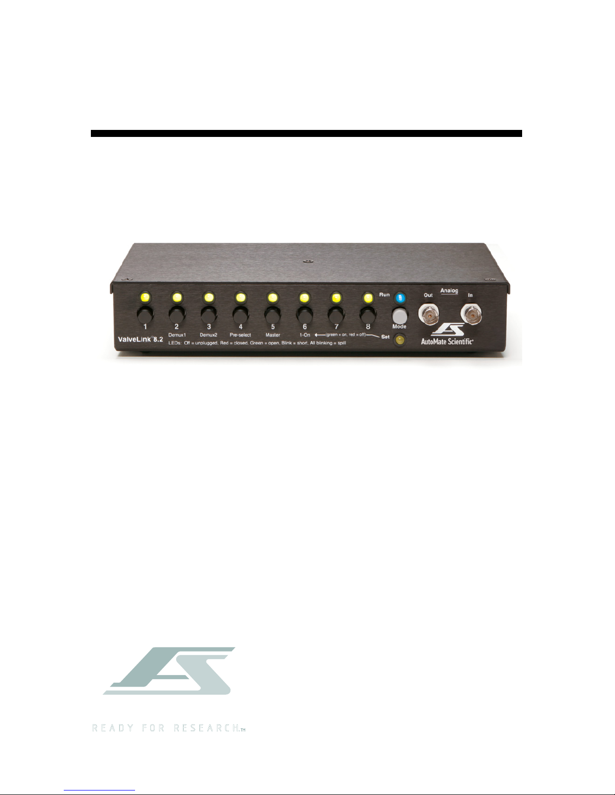
Hardware Overview
The ValveLink8.2® is a digital/manual valve controller designed for use
with research automation software. Valves can be controlled by digital
TTL* signals from any I/O card or device or a single analog voltage input.
Eight pushbuttons allow manual user control with eight bi-colored LED
indicators. A USB (Universal Serial Bus) port is provided for further valve
control and networking by computer. All four input sources (digital,
analog, USB, and pushbuttons) are simultaneously active, and the LEDs
constantly display the current valve status. ValveGuard™ technology
detects bad valves. It prevents damage to your ValveLink8.2 and let's you
easily observe problem valves. A spill sensor protects your equipment
when a leak is detected.
The ValveLink8.2 is designed to drive 12 volt DC solenoid valves plugged
into RCA jacks on the back of the box. Why not connect valves directly to
your computer? Several reasons:
1) Most computer interfaces provide +5V signals – not strong enough
to drive most valves (6 to 12V DC and higher).
2) Computer interface signals are often too noisy for
electrophysiology amplication. The ValveLink8.2 is designed
with special low-noise circuitry to minimize interference with
high-gain amplication.
3) Finally, many solenoid valves are designed to be opened with a
short, full-voltage pulse, then “held-in” with a lower voltage to
keep the valves from heating. The ValveLink8.2 automatically
provides dual-voltage hold-in.
Chromatography
Gel/Blot Washing System
Operation
..................................................................................17
Manual Control
Digital Inputs
Digital Input Port Pin-out
Analog Input
Simultaneous Edge-triggered Inputs
LED Indicators and ValveGuard
™
Event Marker
Spill Sensor
Where is the power switch? Sleep
3-way Valves
Back Panel
Power Supply
Case and Valve Grounding
Modes
.......................................................................................24
Mode Descriptions
Multiple Modes
USB Communications & Software
..........................................27
Installation
Software Operation
Computer Interfacing ...............................................................32
Techniques ................................................................................ 34
Dead Volume
Small-bore PTFE Tubing
Backow
AutoPrime™ System
Faulty Valves
Stuck Pinch Valves
Valve Cables
Valve Returns & Replacing a Valve
Leaks and Replacing Valve Fittings
Hardware Troubleshooting
Safety Instructions ...................................................................40
Warranty ...................................................................................42
Table of Contents Continued
3
2
Page 4
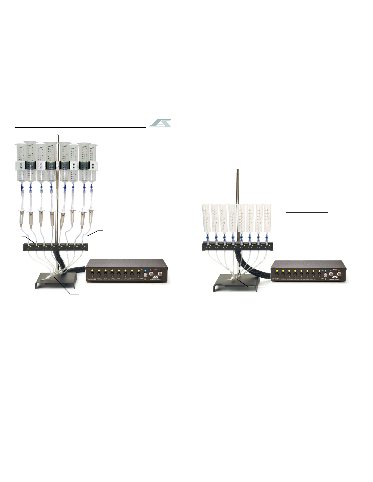
Perfusion Systems
AutoMate Scientic builds ValveLink8.2 and ValveBank perfusion systems
with several choices of valves (below) in 4, 8, or 16 channels. Systems
include reservoirs, drippers, stopcocks, brackets, ow regulator, ringstand,
tubing and micro-manifold. Please visit http://www.autom8.com/build_
your_own.html to congure a custom system to your specications and
generate a quotation.
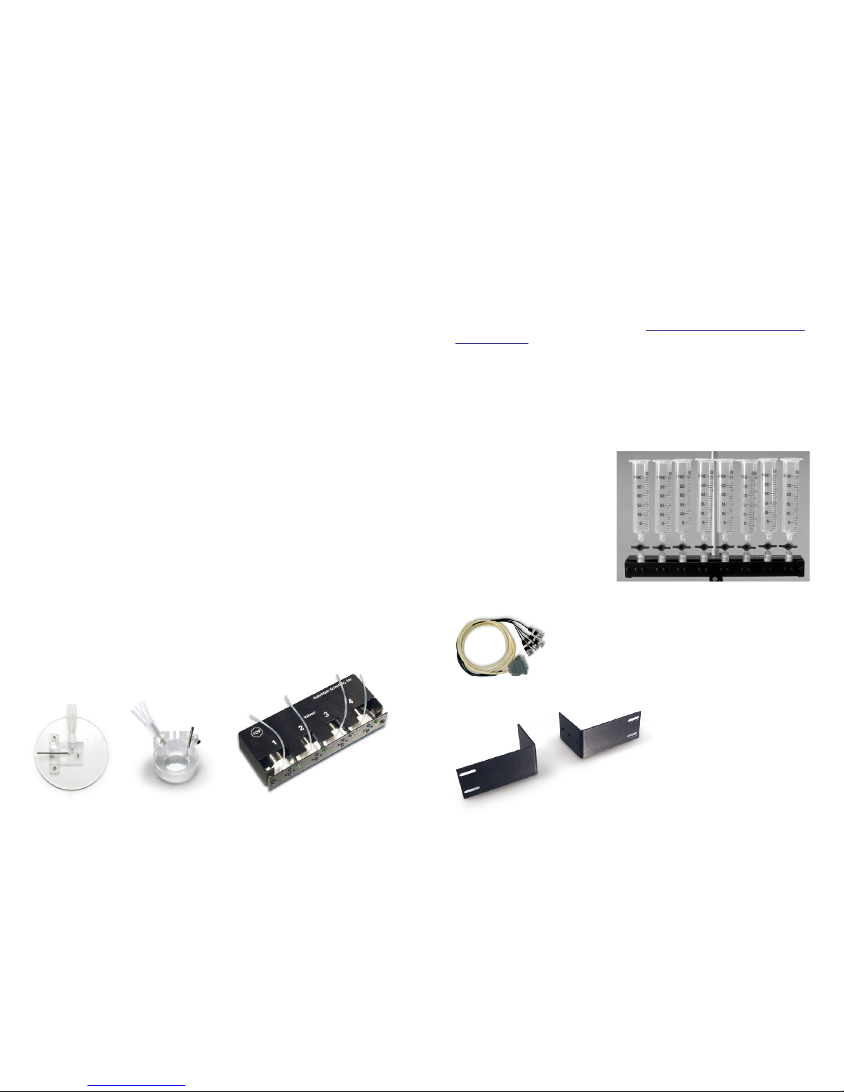
Valves
Solenoid valves are available as part of perfusion systems or sold
separately. We sell 12V DC PTFE and Pinch valves with indicator LEDs
built-in. PTFE valves are faster (open and close in 10 ms.), but pinch valves
are cheaper and easier to clean (open and close in 30-50 ms). PTFE valves
include three choices of
ttings: hose barb (standard),
luer lock, or nut & ferrules for
connecting hard PTFE tubing.
Luer lock ttings allow
direct connection of syringes
as shown. This method
eliminates wasted solution in
tubing between the reservoirs
and valves. Small 2-way
stopcocks are included
with all AutoMate Scientic
perfusion systems. Luer lock PTFE valves
ValveLink8.2 Accessories
BNC cables and rack-mounting brackets make it easier
to connect your ValveLink8.2 to your digital outputs
and to mount the controller in a 19" rack with your
other equipment.
4-BNC cable Part #01-19
AutoMate Scientic also sells
a full range of manual and
motorized micro-manipulators,
ampliers, stimulus isolators,
data acquisition systems, lter
wheels and pipette pullers.
ValveLink8.2 Laboratory Applications
Perfusion
A ValveLink8.2 can be programmed to precisely switch solutions perfusing
over biological samples for physiological research. The ValveLink8.2’s
circuitry is designed to open valves with low noise for electrophysiological
amplication. Several features called ‘Modes’ have been built into the
ValveLink8.2 for advanced perfusion use.
Washing
Combined with an AutoMate Scientic ported washing tray, the
ValveLink8.2 can automate washing of electrophoresis gels and blots, and
developing of x-ray or photographic lm or prints. You have complete
control over which washing steps of your Western, Northern, Southern,
Coomassie Blue and Silver staining runs are automated and which
are handled conventionally. Unattended washing can save a busy lab
countless hours of tedious monitoring.
Liquid Chromatography
A ValveLink8.2 can be easily programmed to automate solution selection
in multi-step ion exchange, gel ltration or anity chromatography runs
with excellent reproducibility. The ValveLink8.2 is especially useful in
preparative work when a protocol has been established and programmed
to repetitively isolate your valuable molecule.
Accessories
AutoMate Scientic oers a number of products which compliment
the ValveLink8.2 controller: valves, pressure upgrades, Perfusion
Pencils®, ThermoClamp™ temperature controllers, perfusion chambers,
manipulators, rack mounting brackets,
BNC cables and entire perfusion systems.
Oocyte Chamber Petri Dish Chamber Pinch Valves (set of 4)
Part #OPC-1 Part #PCP-1 Part #02-pp-04 Rack brackets Part #01-17
5
4
Page 5
Pressure Regulated Perfusion System
AutoMate Scientic oers a Pressurized Perfusion Upgrade with four,
eight or sixteen channels for:
• Faster switching • Steady ow-rate
• Microliter ne delivery • Microinjecting
• Small diameter pipette delivery
The package can be added to any
new or existing perfusion rig from AutoMate Scientic, any
third-party manufacturer, or even
homemade. Connect to house
air, tank, or compressor (30 to 100
psi). Precision regulator delivers
zero to 10 psi to pressurized
syringe reservoirs.
Part #09-04 4-channel
Part #09-08 8-channel
Part #09-16 16-channel
For Single-cell or Whole-cell Superfusion
Perfusion Pencil
®
Multi-Barrel Manifold Tip
4-16 micro-bore tubes into 1 outow
• Rapid solution change with micro-liter
dead volume. No piezo or stepper
motor translation. No clumsy
rotating valves.
• Single-cell and patch delivery.
For mounting on any
micromanipulator.
• 100, 250 & 360µm
removable tips
available
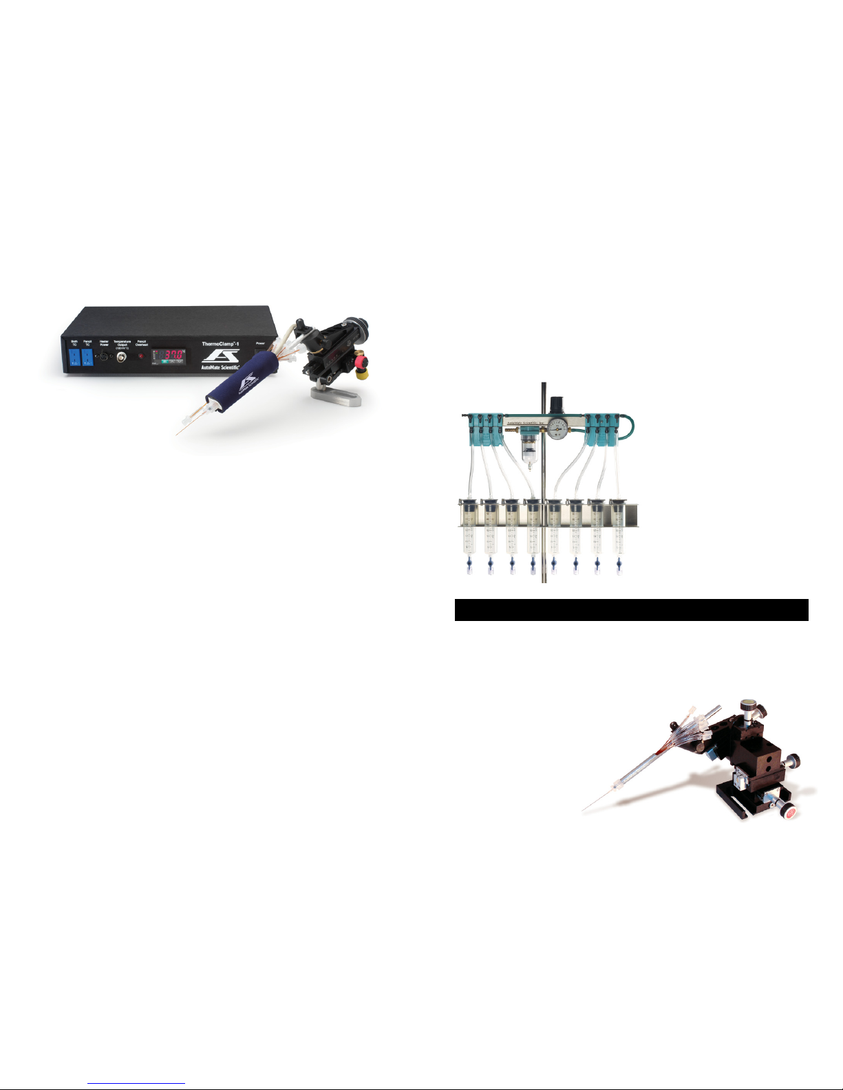
ThermoClamp™-1 Temperature Control System
• Combination inline heater plus multi-channel focal drug delivery
maintain bath temperature and rapid drug wash-out with a high-ow bath
line while quickly switching 4-8 preheated solutions through the Perfusion
Pencil.® Maintain steady 37°C at 5ml/minute ow rates through both the
bath line and tip.
• Advanced auto-tuning temperature lock
Fuzzy logic PID software maintains chamber or reagent temperature
to within 1°C of setpoint or better. The ThermoClamp calibrates
its own tuning for ideal temperature control - no need to guess
“loop speed” settings.
• Designed for physiology research
No metal anywhere in the ow path - unlike some competitors. Low noise
for electrophysiology with internal and external grounding plus electrical
isolation between liquids and heating elements.
• Ready to use
Includes everything you need for heated perfusion: power
supply, temperature sensors, and inline heater with easy luer
lock tube connections.
Part #03-14-xxx ThermoClamp-1 Temperature Control System [4 Channel]
Part #03-18-xxx ThermoClamp-1 Temperature Control System [8 Channel]
Controller, heated Perfusion Pencil, removable tip & bath sensor
xxx = Specify removable tip i.d. size: 100, 250, or 360µm
7
6
Page 6
To chamber
& vacuum
trap (8)
(2)
(3 & 4)
(6)
(5)
1) Assemble ringstand rod and base.
2) Attach valve unit.
3) Attach reservoir bracket(s).
4) Insert syringes with stopcocks.
5) Insert short pieces of
3
/16" i.d. tubing
over tops of drippers, then insert
over syringe ttings.
6) Attach dripper tubing to upper valve
barb. Cut as desired, but leave
long enough to move reservoirs.
7) Insert green clamps on pieces of
1
/16" tubing between bottom valve
barbs and manifold.
8) Connect manifold outow into
your perfusion chamber.
9) Plug numbered valve cables into
ValveLink8.2 ports.
(7) Green clamps
close to manifold
System Set-up Diagrams
Instructions on this page are for Economy perfusion systems, PTFE luer
lock valves, pressurized systems or pinch valve systems. Regular hose
barb PTFE perfusion systems please see the previous page. Luer lock
systems should also see the photo on page 5. Find additional photos and
diagrams of the pressure system on page 15.
(2)
(3)
(4)
1) Assemble ringstand base and rod.
2) Attach valve unit.
3) Insert syringes with stopcocks.
Pinch valves have no ttings.
Simply slide larger tubing over
small pinch valve tube above and
below the valves.
4) Connect tubing between bottom
valve tube and manifold.
5) Connect manifold outow into
your perfusion chamber.
6) Plug numbered valve cables into
ValveLink8.2 ports.
Pinch Valve, Pressurized and Luer-Lock Perfusion Systems
Standard PTFE
Perfusion System
(without pressure)
Also see the "Installation Tips"
section on the next page.
Drippers are NOT included
with these systems because the
syringes are inserted directly into
valves.
Pressurized systems - no room for
drippers and may interfere with
pressure in tubes. Use provided
male luer locks to connect tubing
above each valve.
Roller "thumb" clamps
can be used here
(1)
(1)
(5) To perfusion chamber
and vacuum trap
9
8
Page 7
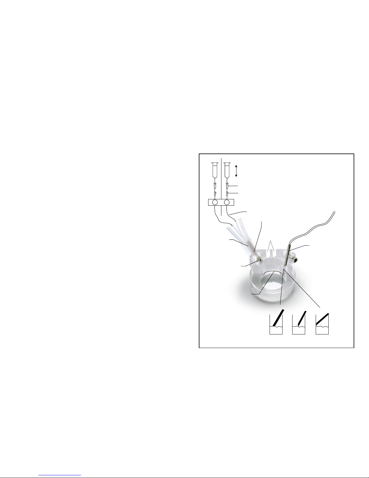
Valves
Adjust flow rate by height of syringe reservoirs.
Watch flow rate in drip chambers
Adjust flow rate with thump clamp
Inflow manifold
Ground
electrode
slots
Suction tube
Flow rate
adjustment
screw
Good liquid level
BAD!
GOOD
May suck chamber dry,
but may stop oscillations.
Caution:
Suction tube well:
Cover and ground
suction tube with
aluminum foil
to minimize noise
As long as these tubes are prefilled (primed)
with solution, then opening valves upstream
starts liquid flowing inside the manifold here.
Perfusion Cheat Sheet
Your perfusion system may not include optional drip chambers, thumb
clamps or the Petri dish chamber, but these hints from Woods Hole
may still help.
Installation Tips
• Flow rate is adjusted by the relative height of reservoirs and manifold
ow regulator plus optional air pressure.
• Leave the tubing between the reservoirs and valves long enough to raise
and lower the reservoirs.
• Unused lines should be replaced with plugs on manifold, or temporarily
clamped-o just above manifold to avoid back bleeding into empty lines.
They MUST also be lled with solution.
• Priming one line at a time reduces bubbles.
• Connect your vacuum trap line directly to the outow of the manifold
for running cleaning solutions and drying your lines quickly.
• Determine dead volume from the manifold to prep by measuring time
and volume required to ush a colored liquid with a clear one. Calibrate
ow rates by running one line into a graduated cylinder for a xed
period of time.
• Filter solutions down to 5-10 microns when using PTFE or Lee valves.
• See more tips in the "Techniques" chapter later in this manual.
Bubbles and Degassing
Bubbles are often caused by outgassing. This is particularly true when
media is stored cold overnight and allowed to warm to room temperature
in the perfusion system tubing. Since warm liquids hold less gas, bubbles
will form in the tubing and valves as gas leaves the media. The best
solution is to pre-warm your solutions by at least 2-3 degrees above
room temperature even if you are adding gas (CO2, Carbogen, etc.) to
your reagents. If you are using an inline heater like the ThermoClamp,
it is a good idea to warm solutions 2-3 degrees above your inline heater
temperature to prevent bubbles from forming there. If possible, keep
the solutions in the reservoirs at this higher temperature all day using
reservoir heaters.
Degassing can also be facilitated by applying a slight vacuum to the
reservoirs, although this is not recommended if you are purposely gassing
your media.
11
10
Page 8
Pinch Valve Tubing
Pinch valves have no ttings. Simply slide larger tubing over small pinch
valve tube above and below the valves. The tubing in each pinch valve
can be replaced for easy cleaning. It is 1/32" i.d. x 1/16" o.d. silicone tubing.
We have only found one type of tubing this size which works well in these
pinch valves. AutoMate Scientic sells this replacement tubing as part
#05-14. The tubing can be removed from the valves even when they are
closed. Remember that any liquid remaining in the tube may spill when it
is removed from the valve. New tubing can be installed while the valves
are closed, but it is much easier if they are opened/energized. If you are
concerned about the same piece of tubing being squeezed for long periods
of time, you can slide the silicone tubing up or down in the valve by a
few millimeters to expose a new section to the plunger. The same piece of
tubing can be used for years without fatigue.
Valve Care
Rinse PTFE valves every day. Do not get pinch valves wet. See sections
on Faulty Valves, Stuck Pinch Valves, Valve Cables, Replacing Valves and
Leaks in the "Techniques" chapter later in this manual.
Perfusion Pencil Flow Rates
360µm Removable Tips (reservoir height 40cm)
Gravity (full reservoir) 1.15ml/min +/- .04
2psi air pressure 3.98ml/min +/- .08
8psi air pressure 10.66ml/min +/- .27
250µm Removable Tips (reservoir height 40cm)
Gravity (empty reservoir) 0.35ml/min +/- .05
Gravity (full reservoir) 0.45ml/min +/- .05
2psi air pressure 1.66ml/min +/- .14
8psi air pressure 5.16ml/min +/- .04
100µm Removable Tips (reservoir height 40cm)
Gravity 0
2psi air pressure 0.07ml/min = 4.6ml/hour
8psi air pressure 0.25ml/min = 15ml/hour
PTFE Micro-manifold Use
To use the micro-manifold, you either need pinch valves or PTFE valves
equipped with 1/16" o.d. outow hose barbs. Micro-manifolds are shipped
with a short piece of 1/16" o.d. tubing in each hole (inputs and outow).
You can either connect the valves to manifold inports with a piece of 1/16"
i.d. tubing over both the valve barbs (or pinch tubing) and short pieces of
manifold tubing:
Valve with 1/16" o.d. barb or pinch tubing
v
1
/16" i.d. tubing over barb/pinch tube
and over manifold short tubing
v
Manifold with short pieces of 1/16" o.d. tubing in each port
... or, for even less dead volume, use a short piece of 1/16" i.d. tubing over
the valve barb (or pinch tubing), and piece of smaller 1/16" o.d. tubing
inserted inside the secondary tube and manifold ports (you may need to
supply extra small PE-160 or PTFE tubing for this option):
Valve with 1/16" o.d. barb or pinch tubing
v
Short piece of 1/16" i.d. tubing over valve barb/pinch
v
Small diameter 1/16" o.d. tubing inserted inside valve tube
and inserted inside manifold ports
v
Manifold without connector tubing. 1/16" holes.
Cutting the tubing at an angle and wetting it will make insertion easier.
Cutting the tubing square, however, will minimize dead volume when
inserted as far as possible into the manifold – being careful not block at the
point of convergence. Remember to keep all tubing as short as possible.
Use the provided Allen wrench and small screw near the manifold outow
to adjust ow rate. AutoMate Scientic now sells small PTFE manifold
'stoppers' for plugging unused manifold ports as part #05-05 for a set of
four.
13
12
Page 9

Perfusion Pressure Kit
(Sold separately)
Hoses should continue from syringes to valves.
Syringes may also be placed in a water
bath for temperature control.
Brass input connector hose barb size 1/4”
5 micron bowl lter.
Press bottom button to empty.
Be very careful with these
plastic hose connections.
Press regulator knob down to lock.
Pull up to unlock.
Individual air lines can be
adjusted or turned-o.
2-way stopcocks and luer-lock to
1
/16” hose ttings are
included for each channel to connect syringes to hose.
Max. input
pressure 100 psi!!
Perfusion Pencil Multi-barrel Manifold
(Sold separately)
Tighten removable tip for
minimum dead volume.
One of the eight lines may be connected to
vacuum through a valve programmed to suck
the dead-volume clear between solutions.
Chemical Information
The tubing inside the manifold body is polyimide (nylon). The removable tips
include a polycarbonate luer lock tting with a fused silica (quartz) needle coated
with polyimide. These materials are resistant to most acids, bases and organic
solvents. To avoid dust contamination, we recommend pre-rinsing the Perfusion
Pencil and tip with distilled water. Also, it is good practice to discard the rst few
microliters of solution before using the device. The Perfusion Pencil and removable
tips are shipped non-sterile. They can be chemically sterilized or autoclaved.
However, repeated autoclaving may weaken the adhesive bond between the luer
lock tting and the needle.
Maintenance
You can expect several years of useful lifetime for your tip if you wash it daily.
Use a syringe or vacuum to pull water, then alcohol three times each through the
tip. If the Perfusion Pencil is lled with pure salt solution, leaving it in the syringe
overnight will not usually cause the tip to block. However, if it is used for high
viscosity uids, ushing after each use is recommended.
Cutting
The removable tips are shipped with 0.5" (1 cm) length polyimide needles.
They can be cut shorter by rolling a razor blade on them against a hard surface.
However, this may leave a small crack or barb on the tip. To get a at cut, score the
coating of the needle with a ceramic cleaving stone or a diamond cutter and pull
directly apart, making sure not to pull at an angle. You may notice a larger outer
tube enclosing the lower part of our smaller, 100µm needles. This is simply for
added rigidity, and can be cut if needed.
Replacement Tips:
#04-xxx Specify i.d. size:
100, 250, or 360µm
All inow tubes must be lled with solution
before use even if some lines are not needed, or
liquids will backow into empty lines!
Part No.
#04-04-xxx 4-into-1 Pencil with tip
#04-08-xxx 8-into-1 Pencil with tip
#04-16-xxx 16-into-1 Pencil with tip
(xxx = 100, 250, or 360µm)
15
14
Page 10

Operation
With a ValveLink8.2, a researcher can turn valves on and o using:
• front-panel manual pushbuttons
• digital inputs
• analog input
• or USB port and software (see USB chapter).
LED lights on the front of the controller indicate valve status. The
ValveLink8.2 sends an analog voltage out the "event marker" BNC on the
front panel every time a valve is opened or closed. This marker can be
recorded using a single channel for a permanent record of valve activity
synchronized with a physiological recording. Also, a spill sensor is
monitored to close all valves in case a liquid overow happens. This can
save precious reagents and protect valuable microscope equipment in
the event of a spill. With no power switch, the ValveLink8.2 can be put
to sleep by holding the "Mode/Sleep" button for three seconds. Press the
same button to wake from sleep. Descriptions of these features follow...
Manual Control
Each press of a front-panel pushbutton toggles its valve on and o subject
to Mode settings described in the next chapter. The buttons can be pressed
even when the ValveLink8.2 is being controlled by an external device or
computer. Press the "Mode/Sleep" button for three seconds to close all
valves quickly (and put the ValveLink8.2 to sleep - see below).
Digital Inputs
Eight TTL pins (wires) can be used to listen to outputs from interface
hardware on a personal computer or other digital sources. The
ValveLink8.2 will open and close valves mirroring the computer signals
(low = o, high = on) with one millisecond accuracy. Usually data
acquisition software like pClamp, Pulse, LabView, etc. or custom user
software is programmed to send digital signals to open and close valves
at specied times. Each input pin (1-8) represents one valve. This way all
eight valves can be operated independently by eight computer outputs.
See the description of Modes #2 and #3 in the next chapter to control
eight or sixteen valves using only three or four TTL outputs. Read the
"Computer Interfacing" chapter for more information on connecting the
ValveLink8.2 to data acquisition software and hardware.
Chromatography
1234
Fraction
collector
or waste
Without a pump, ow rate
is determined by relative
height of reservoirs.
1) Position reservoirs above
column ringstand.
2) Attach valve unit to
column stand.
3) Run tubing from
upper valve barbs into
reservoirs.
4) Connect short pieces of
tubing between lower
valve barbs & manifold.
5) Connect manifold outow
to your pump with 1/16"
i.d. tubing.
6) Pump outow connects to
column inlet as usual.
7) Plug numbered valve cables
into ValveLink8.2 ports.
1234
Flow rate is determined by
relative height of reservoirs.
1) Position reservoirs above
washing area.
2) Attach valve unit to
ringstand.
3) Run tubing from upper valve
barbs to reservoir nipples.
4) Connect tube from lower
valve barbs to tray inlets.
5) Connect tray outow to
fourth upper valve barb.
6) Connect this valve’s outow
to vacuum trap.
7) Plug numbered valve cables
into ValveLink8.2 ports.
Vacuum trap
Gel/Blot Washing System
Rocker
17
16
Page 11

from low to high, that valve opens. Then the ValveLink8.2 ignores that
input until it changes (high back to low) again. If that valve's manual
pushbutton is pressed, it toggles the valve from open to closed or vice
versa - regardless of the state of its other inputs. Therefore, whichever
input happens last determines the state of the valve.
LED Indicators and ValveGuard
™
The eight numbered valve LEDs on the front of the ValveLink8.2 give you
the current status of each valve. They can each be in one of four dierent
states:
Red = Valve plugged-in but closed
Green = Valve plugged-in and open
O = No valve plugged-in or broken valve wire
Flashing red = Short-circuit detected in valve wire
These last two states represent our ValveGuard technology. Special
circuitry detects a good valve resistance or short-circuit. Broken or shorted
(crossed) valve wires used to be the biggest cause of valve failure and
controller damage. Now these two problems are easily observed and
isolated before they can damage the controller. See the "Valve Cables"
section in the "Techniques" chapter later in this manual to repair a broken
valve cable yourself.
Press the valve button to clear a ashing short signal and try opening the
shorted valve again. If all LEDs are ashing it means the spill sensor has
been tripped. See the Spill Sensor section below. The ValveLink8.2 will not
even try to open a valve which is not plugged-in (its LED is o).
Event Marker
The ValveLink8.2 outputs a 10 millisecond voltage pulse on its front-panel
analog output BNC as an event marker every time a valve opens or closes.
The marker voltage occurs regardless of how the valve was opened or
closed (i.e. manual pushbutton or computer digital input). This voltage
can be easily recorded with a single channel of your data acquisition
software for a permanent, synchronized record of valve activity. Here are
the voltages sent by the ValveLink8.2:
+2.5 volts is the baseline when nothing is happening. Valves opening
create a 10 millisecond pulse upwards, while closing valves cause a
Digital Input Port Pin-out
[Back panel diagram view]
Standard female DB-9 connector
pin# pin#
1 = ground 6 = TTL8
2 = TTL7 7 = TTL6
3 = TTL5 8 = TTL4
4 = TTL3 9 = TTL2
5 = TTL1
AutoMate Scientic sells BNC cables with four or eight TTL inputs
wired to BNCs for you. Parallel port and Heka EPC / ITC cables are
also available.
Analog Input
The front panel "Analog Input" BNC accepts a 0-5V DC signal to open a
valve using only a single analog output from your computer. Here are the
voltages it accepts:
0 (zero) volts = All o
Ch 1 2 3 4 5 6 7 8
Voltage 0.5 1.1 1.6 2.1 2.7 3.3 3.9 4.6V
Changing from one voltage to another closes ALL other valves.
Simultaneous Edge-triggered Inputs
You may be wondering how the ValveLink8.2 can respond to so many
inputs simultaneously -- digital, analog and pushbuttons all at the same
time. If a digital input is "high," then shouldn't that valve be open? How
can you close it by pushing the button? The answer lies in an electronics
concept called "edge triggering." Rather than watching the state of an
input (i.e. high or low TTL input), the ValveLink8.2 watches for a change in
state (i.e. rising or falling edge of TTL input). When a TTL input changes
15
9
6
19
18
Page 12

This ValveLink8.2 analog output graph shows the voltage resulting from
valve #7 (4.67V) opening at time 8.07 seconds, then valve #3 (3.43V)
opening with Mode #6, "1-On" active. This immediately closes valve #7
(0.33V). The output returns to "baseline" of 2.5 volts after each 10ms pulse.
Spill Sensor
A two-pin socket on the ValveLink8.2 back panel accepts a 3mm Molex
"Microt" female plug for a spill sensor. The spill sensor circuitry watches
any wires plugged-into this ValveLink8.2 port for a drop in electrical
resistance representing a liquid spill. In perfusion work spills usually
occur when the chamber vacuum stops or the vacuum trap lls-up. The
spill sensor circuitry immediately closes all valves and begins blinking
all LEDs to notify you of the spill. The ValveLink8.2 remains in this state
until you press any button to override the spill. After you clear the spill
warning, you may immediately begin opening valves again.
AutoMate Scientic provides a spill sensor made of Mylar tape and two
closely-spaced copper contacts. When liquids cross this tape, they make
contact with both copper strips simultaneously and complete an electrical
path for the spill sensor circuitry. In this way a drop of liquid passing
the sensor strip appears as a sharp drop in electrical resistance between
the two, otherwise disconnected copper conductors. Even distilled water
will conduct enough current to trigger the sensor. The adhesive tape
is designed to be placed around the at outside edge of your perfusion
negative pulse. The voltage is 2.5 ± (valve# x 0.31V). For example,
whenever valve 4 opens, a 10 millisecond pulse appears on the analog
output at 2.5 + (4 x .31) = 3.74V. When the same valve #4 closes, it creates a
pulse of 2.5 - (4 x .31) = 1.26V.
This graph shows the analog output voltage vs. time resulting from each
valve opening and closing twice.
ValveLink8.2 Modes #2, #3 and #6 (see next chapter) and the analog input
automatically close other valves when a new one is opened to insure that
only one liquid is owing at a time. If the user opens a valve in this way,
then any others will close at the same time. In order to indicate valves
opening and closing simultaneously on the event marker output, the
controller will give a short voltage spike upwards representing the valve
which opened, and immediately spike downwards to the appropriate
voltage for the remainder of the 10 millisecond pulse to signify the valve
which closed.
Valve #5 closing =
2.5 - (5 x .31) = 0.95V
21
20
Page 13

3-way Valves
The ValveLink8.2 also supports 3-way, single-solenoid valves (2 wires
each). Operate the ValveLink8.2 as you normally would for 2-way valves,
after determining which of two inlets or outlets are opened with the on and
o states. Note that one inlet will always be open with these valves.
Power Supply
The ValveLink8.2 is normally supplied with a 1.5 amp wall transformer.
This is adequate for any valves provided by AutoMate Scientic or a
total of 1 amp of valves opened simultaneously. Please contact AutoMate
Scientic to request a larger power supply if you wish to exceed 1 amp of
valve power (i.e. two 12 watt valves opened at once).
Case and Valve Grounding
This equipment must be earth grounded. Use a #6 screw in any hole
on either side of the ValveLink8.2 case for grounding. Order AutoMate
Scientic part no. 01-05 “Low noise, valve and case grounding package”
for an extra grounding wire attached to each individual valve extending
back to the controller. Each of these items grounds four (4) valves. Please
order two for eight channel perfusion systems. This item must be ordered
at the same time as the valves. Connect the ground wire from the valves to
a screw on the side of the controller case or to your rig's ground point.
chamber where liquid would pass if it overows. It can also be wrapped
around the outside of a light condenser or inverted microscope objective
turret where liquid would ow if it drips out of the perfusion chamber.
Researchers may create or use their own spill sensors with the
ValveLink8.2. Conductive mats or other commercially-available spill
sensors generally use the same principle as AutoMate Scientic's copper
strips. Likewise, you can easily create your own custom sensor using two
bare wires or conductive pens or epoxy. Inexpensive conductive pens
like those from "Circuit Works
™
" are designed for repairing circuit boards.
They leave lines which quickly dry into silver traces. A similar conductive
epoxy is also available. It makes the connection of two wires to your silver
traces even easier. Simply draw two parallel silver lines approximately
1
/16" (1 mm) apart on any surface where leaking liquids would pass. Make
sure the lines do not touch, or draw one wide line and etch a gap down the
middle once it has dried. Then connect a small wire from each trace back
to the spill sensor port on the ValveLink8.2.
Another nice feature of the ValveLink8.2 spill sensor circuit is its dynamic
recalibration. Competing spill sensors simply watch for a low resistance
and trigger. Unfortunately, their conductive mats keep a low resistance
and cannot be reused until they dry. The ValveLink8.2 lets you press
any button to override the spill. Because it is microprocessor-based, the
controller keeps a running value for the sensor resistance and watches for
a 5% drop in resistance. Therefore, even a damp sensor can be used again
immediately as the controller adjusts to the new resistance and watches for
any subsequent leaks by another proportional resistance drop. As the mat
dries, the ValveLink8.2 is constantly monitoring the increasing resistance
and watching for a drop from the latest value.
Where is the power switch? Sleep
The ValveLink8.2 does not have a power switch. As long as it is pluggedin, it is on. The ValveLink8.2 is perfectly happy being left on forever
and consumes very little power when all valves are closed. However, an
optional sleep mode has been included. Press and hold the "Mode/Sleep"
button until the blue and yellow Mode LEDs begin ashing (about three
seconds) to put the ValveLink8.2 to sleep. In this state all valves and valve
LEDs are o, and all inputs (buttons, TTLs, USB, etc.) are ignored. Press
the Mode button again to wake the controller. Sleep mode can also be used
as an emergency "o" switch if you need to quickly close all valves and
stop the computer inputs.
12V AC Power (up to 2.4 amps @ 50-60Hz)
USB Port and address
(see USB chapter)
Digital inputs
(see earlier section)
Back Panel
12 volt DC valves
1A (12W) max per channel
2A (24W) max total
Spill
sensor
(prev. pages)
23
22
Page 14

Modes
The ValveLink8.2 includes several useful features as auxiliary ‘Modes.’
The user changes the current mode settings by pressing the "Mode" button.
The yellow "Set" LED will light. Individual modes are toggled on and o
by pressing their button. The LED associated with each button should
toggle from red to green, with green representing ON. All of the modes
can be used simultaneously, except numbers #2 and #3 which cannot both
be on. Press the "Mode" button to return to normal ValveLink8.2 operation
with any modes activated.
Mode Descriptions
#2 Binary Demultiplexed Addressing Mode
(Valves 1-8 for two ValveLink8.2s)
TTL inputs 1-3 decode into a binary number 0-7 representing which
valve to open (see chart below). Example: TTL input 0000 0101 opens
valve 6 (its decimal equivalent + 1). When this 3-bit number changes, the
previous valve is closed. When Mode #2 or #3 is used, TTL inputs 1-4 are
used for addressing and no longer directly control valves 1-4. For two
ValveLink8.2s, bit 4 is used as described below to further select bank 1 or 2.
Binary chart (showing TTL inputs 4321)
Digital bit pattern Decimal Valve
0000 0 1 (decimal + 1)
0001 1 2
0010 2 3
0011 3 4
0100 4 5
0101 5 6
0110 6 7
0111 7 8
1000 8 + 0 1 on second ValveLink8.2
See Mode #3 below.
The only drawback to either addressing mode is that only one valve can
be opened by TTL inputs at a time. Without Mode #2 or #3, each TTL
input corresponds to a single valve and multiple valves can be opened
simultaneously. Because Modes #2 and #3 need several TTL inputs to
select a single valve, only one can be opened in this manner at once. The
ValveLink8.2 will automatically activate Mode #6, "1-On" whenever Mode
#2 or #3 is used.
#3 Addressing Mode - Valves 9-16 (2nd ValveLink8.2)
This is the same binary decoding of bits 1-3 as Mode #2, but bit 4 is used to
select between two ValveLink8.2s and control up to 16 valves with a single
4-bit TTL source. Set the rst ValveLink8.2 to Mode #2, set the second to
Mode #3, and connect TTL input bits 1-4 from both ValveLink8.2s to your
digital output. Bits 1-3 decode which valve is opened on the ValveLink8.2
selected by the fourth bit (high = ValveLink8.2 in Mode #3 & low =
ValveLink8.2 in Mode #2). Example: TTL input 0000 1001 opens valve 10
(valve 2 on the second ValveLink8.2.) As in Mode #2, TTL inputs 1-4 are
used for addressing and no longer directly control their respective valves.
BNC "tee" connectors will facilitate connection of BNC cables from two
ValveLink8.2s to a common set of digital outputs.
#4 Pre-selected Valve Mode
When Mode #4 is activated, the user is prompted to select a channel 1-8
when leaving mode selection. All LEDs will ash waiting for a channel
selection. Press "Mode" again to nish. Thereafter, the selected valve is
toggled on and o by TTL input bit #8. This mode allows a researcher to
permanently connect a single TTL output to ValveLink8.2 input eight, and
select which of eight valves to activate with that single TTL signal. This
mode prevents input #8 from controlling valve #8 as it normally would,
unless valve #8 is chosen as the ‘pre-selected’ Mode #4 valve.
#5 Master Valve
When Mode #5 is selected, the user is prompted to select a channel 1-8
when leaving mode selection (like Mode #4 above). This valve then
becomes the master valve. Whenever all other valves have been closed
through pushbuttons or any inputs, the master valve will automatically
open. This feature is useful if a control solution is required whenever all
other solutions are stopped.
#6 One-at-a-time or "1-On" Mode
When active, Mode #6 automatically closes all other valves whenever a
valve is opened – either by pushbutton, TTL, analog or USB input. This
guarantees that no more than one valve is open at a time. This mode is
automatically activated when Mode #2 or #3 is used.
25
24
Page 15

USB Communications & Software
The ValveLink8.2 includes a USB-1 port for easy connection to a computer.
The connector is a USB "B" style female socket. AutoMate Scientic sells
USB "A" male to "B" male cables and 4-port USB hubs for use with the
ValveLink8.2. AutoMate Scientic oers a free program for Microsoft
Windows 2000 and above called "ValveLink8.2 User Interface." This
program allows manual control of valves from your PC and networking
of up to eight ValveLink8.2s. It can be downloaded from AutoMate
Scientic's web site at http://www.autom8.com/valvelink.html.
Screen shots show Windows XP, but ValveLink software also works on Vista to Windows 10.
Installation
If you have one, insert the ValveLink8.2
CD into your computer and follow
the instructions to install the main
application. Or double-click the "setup.
exe" installer you have downloaded
from AutoMate Scientic's web site.
Once the program is installed you can plug a USB A-B cable into the
ValveLink8.2 (powered ON) and into your running computer.
Depending on your version of Windows, the rst time a ValveLink8.2 is
installed by USB cable, Windows will "nd new hardware." A dialog box
will appear asking if you want Windows to connect to Windows Update to
search for the necessary software drivers. Select "Yes" and click "Next" to
continue.
If Modes #4 and #5 are both active, the user will be prompted for the Mode
#4 ‘pre-selected’ valve rst, then the Mode #5 ‘master’ valve when leaving
mode selection. If Modes #2-4 are turned-o, then the TTL inputs resume
direct control of their respective valves.
Multiple Modes
As mentioned above, most of the ve modes above can be active
concurrently, such as Mode #2 - Addressing, Mode #5 - Master Valve, and
Mode #6 - One-at-a-time. Valves are opened or closed accordingly. Only
Modes #2 and #3 cannot both be on simultaneously.
Example mode selection LEDs (red = o, green = on):
1 2 3 4 5 6 7 8
Dark Red Grn Red Grn Grn Dark Dark
#3 on = Addressing Mode valves 9-16 (2nd ValveLink8.2)
#5 on = Master Valve
#6 on = One-at-a-time Mode
In this example, when the "Mode" button is pressed to leave mode
selection, all LEDs will ash waiting for the master valve (Mode #5) to be
selected. Select a valve and press "Mode" again to nish.
27
26
Page 16

In the next dialog box, select "Install automatically" and click "Next." Your
computer may need to access the internet.
You may see a warning box explaining:
"The software you
are installing for this
hardware:
FTDI FT8U2XX
Device
has not passed
Windows Logo
testing to verify
its compatibility
with Windows.
Continuing your
installation of this
software may impair
or destabilize the correct operation of your system..." Click "Continue
Anyway" and "Finish" the hardware installation.
Your computer may "Find new hardware" a second time. Repeat the two
steps abaove again, and your computer will be ready to run the ValveLink
sofware.
Software Operation
After the ValveLink8.2 software and USB drivers are installed on your
computer, you may run the program. Any ValveLink8.2s currently
plugged-into the
computer or USB hubs
will appear in the System
Status box as "Online"
next to their USB address.
This address comes from
the 8-position rotary
switch on the back
of each ValveLink8.2
next to its USB port. If
you connect multiple
ValveLink8.2s to the
computer, be sure to set
each one to a dierent
address.
If you connect a ValveLink8.2 to the computer while the User Interface
program is already running, click "Discover Controllers" under the System
menu to add it. The System Status window also shows the current version
of the rmware (internal programming) of each ValveLink8.2. You can
visit AutoMate Scientic's web site to check the latest rmware version,
but it can only be updated by AutoMate Scientic at its oce.
Each ValveLink8.2 will display its own control window with its Address
and eight LED buttons of each valve. These buttons should mirror those
on the front of the ValveLink8.2 and clicking the buttons should toggle
valves exactly like the real buttons.
Depending on your computer's speed and USB bus, there may be a
noticeable delay between the real ValveLink8.2 buttons and LEDs and
updates on your computer screen. USB communications in Windows
are not necessarily real-time. A 100 millisecond delay is not uncommon.
29
28
Page 17

If the CPU is busy with other programs, printing, or lots of trac on
the USB bus, then signals to and from the ValveLink8.2 may suer. For
maximum performance, plug the ValveLink8.2 into a USB port connected
to its own USB bus. Remember that computers with multiple USB ports
may simply be splitting a single USB bus internally. Check with your
computer's manufacturer or add a separate USB card to your computer for
minimum latency.
The System Status window has a large switch labeled "Local Control"
and "Remote Control." When set to "Local," each ValveLink8.2 follows
its own Mode settings as
described in the "Modes"
chapter earlier in this
manual. When set to
"Remote Control," all
networked ValveLink8.2s
behave according to a single
common "Mode" setting
made on the System Status
window. In this way, up
to eight ValveLink8.2s can
be networked into a single,
virtual 64-channel controller.
A single "Master Valve" can
be selected on a "Master
Controller" like Mode #5 on the ValveLink8.2. Also "1-on" Mode means
only one valve will be open at-a-time on all of the networked controllers.
When the System Status switch is set to "Local Control" you can click the
"Mode" button on any ValveLink8.2 sub-window to access a dialog box
of Modes for that ValveLink8.2 along with eight text "labels" which will
display under each button. These labels can be used to help identify which
solutions are being delivered through each valve.
The same comments about USB communications speed above also apply
to multiple-ValveLink8.2 networking. If "1-on" Mode is used and a button
is pressed on one ValveLink8.2, that signal must travel to the User Interface
program on the PC and back to all other ValveLink8.2s to close any
open valves. The double delay may be noticeable on slower computers
or USB busses.
AutoMate Scientic chose the older USB-1 protocol over the newer, highspeed USB-2 architecture for three reasons: 1) less expensive, 2) older
computers don't have USB-2 ports, and 3) USB-2 has more bandwidth
(transfers large amounts of data faster), but the same latency (delay) as
USB-1. The ValveLink8.2 needs short bursts of data quickly, so USB-2
would not help.
*This software requires Windows .NET version 4.0 or higher be
installed.
31
30
Page 18

Computer Interfacing
The ValveLink8.2 can be controlled from a computer using its digital
inputs, analog input or USB port. AutoMate Scientic supplies free
software for communicating over the USB port, but the digital and analog
inputs require you to provide software to generate the signals. Most
customers use their data acquisition software like Axon Instruments'
"pClamp" or Heka's "Pulse." General I/O software like "LabView" from
National Instruments also works well.
You can directly control individual ValveLink8.2 valves from your
computer using one digital output per valve, or you can control all eight
valves with just three digital outputs using Mode #2 or 3 described in
the "Modes" chapter. Computer digital signals are also called "TTL" for
Transistor-Transistor Logic. An "on" or "high" signal is +5V and "o" or
"low" is zero volts. Almost any analog output can also produce these
two voltages. Therefore, if you do not have enough digital outputs, then
analog outputs can also be used to drive the ValveLink8.2 when set to
either +5 or 0V. When the input goes high, a valve opens, and when it
drops low, the valve closes again.
While AutoMate Scientic generally does not support software or
hardware from other companies, we have accumulated some instructions
for connecting the ValveLink8.2 to pClamp software and DigiData
hardware from Axon Instruments. These instructions may help even if you
are using other software.
1) Connect one or more pClamp/DigiData digital outputs to the
corresponding ValveLink8.2 digital inputs (and ground) using the wiring
diagram on page 18 of this manual, or an AutoMate Scientic-supplied
BNC cable. DigiData digital outputs 0-3 appear as BNC connectors on the
front panel. Digital outputs 4-7 are located on the back panel of newer
DigiData interfaces. Older DigiData 1200’s only have four outputs.
2) The ‘Modes’ chapter explains the two dierent methods of controlling
valves: Demultiplexed or not.
3) You can manually generate digital outputs 0-3 from Clampex using the
‘Real Time Control Panel’ adjacent to the ‘Scope’ window. Click the four
checkboxes to turn the outputs on or o and test your connection.
4) To program the digital outputs from pClamp you have two choices:
Sequencing Keys/User Lists or Waveform - Epochs.
Sequencing Keys/User Lists:
Clampex lets you program activities as “Sequencing Keys” (Cong menu)
which can include digital outputs (Operations tab / Parameters / Digital
Out Bit Pattern). The Sequencing Keys can be assigned to hot keys or
grouped together into “User Lists” (Acquire menu / New Protocol /
Stimulate / User List). Each Sequencing Key becomes one ‘step’ in your
perfusion/recording experiment, and can be assigned a time duration.
It is also possible to link Sequencing Keys into a series without needing
User Lists. You can also program a “Digital Holding Level” (Lab Bench /
Congure / Overrides) which maintains a valve state between protocols.
Waveform - Epochs:
The bottom of each Epoch column on the Protocol / Waveforms screen
oers a set of four digital bit patterns. This way you can program valve
activity for each recording epoch interval.
Also see the “Scenarios” section of the “Experiments” chapter of your
pClamp manual. The “Isolated Patch-Clamp Single-Channel Recording”
section (manual page 125 or 135) describes triggering with a drug
application system (DAS).
Contact AutoMate Scientic for advice on how to program your computer
to control valves, or to purchase cables for connecting the ValveLink8.2 to
your I/O hardware.
33
32
Page 19

Techniques
Dead Volume
Dead volume should be minimized in order to switch solutions as rapidly
as possible. Dead volume for this purpose refers to the volume between
the manifold (or Perfusion Pencil) and nal destination (perfusion
chamber, 96-well plate, etc.) A certain amount of time must pass for a new
liquid to clear the previous one from this nal piece of tubing. Solution
switching takes place at the manifold - assuming each channel’s tubing has
been primed (lled) from its valve to this point. Therefore, the manifold
should be positioned as close to the ultimate destination as possible, while
the valves can be some distance away. The micro-manifolds available
from AutoMate Scientic are designed to be inserted directly into orices
in some perfusion chambers. This absolutely minimizes dead volume –
resulting in bath switching times of under a second.
AutoMate Scientic Perfusion Systems may include a disposable ow
regulator which will increase dead volume if used improperly. The
regulator can either be eliminated if controlling ow rate is not necessary,
or positioned before the manifold to eliminate dead volume. However, this
second method only controls the ow rate of individual solutions (instead
of all solutions when located after the manifold). Therefore, the researcher
can either limit the ow of a single liquid, or purchase ow regulators
for each line.
A nal method for reducing dead volume is to use smaller bore tubing,
although this may also reduce ow rate resulting in the same switching
time as for larger tubing.
Small-bore PTFE Tubing
AutoMate Scientic’s micro-manifolds use 1/16” tube ports which can
either be used with 1/16” o.d. tubing, or enlarged up to 1/16” i.d. tubing for
standard Tygon tubing. Please inquire about AutoMate Scientic’s PTFE
tubing and nut and ferrule valve ttings for small bore use. Also see the
micro-manifold instructions on page 12.
Cutting PTFE tubing at an angle and wetting it makes it easier to insert.
Backflow
When a manifold is used in a plumbing arrangement, none of its ports
can be left unconnected, or liquid will simply ow backwards out of the
opening. Small, green hose clamps are included with AutoMate Scientic
Perfusion System drippers which can be easily attached to short pieces
of tubing to act as plugs for unused holes. AutoMate Scientic also sells
manifold 'stoppers' for plugging unused manifold ports.
Likewise, one must be careful not to open any valve whose reservoir
is completely empty or inow tube is disconnected. Ordinary solution
pressure in other lines will force liquid back up the outow tubing,
through the valve, and either back into the reservoir or out the
disconnected inow onto the oor. Again, clamp-o any unused lines at
the manifold or be sure all valves are closed while changing connections.
Solution will quickly backow into empty tubes even when their valves are
closed because air is so compressible. Fill all tubes down to the manifold
or Perfusion Pencil with solution even if they are not being used.
AutoPrime™ System
The AutoPrime Perfusion System is
designed to deliver oxygenated (or
other gas-saturated) solutions without
administering ‘stale’ liquid which has
remained stationary in the tubing long
enough to lose its oxygenation. Unless one
uses ‘hard-walled’ (i.e. PTFE) tubing, gas
will escape through the tubing leaving the
stale solution with a ruined pH and gas
concentration. The 8-channel AutoPrime
System uses eight valves per four liquids,
with the second set used as ‘ush’ valves
to waste. Shortly before a solution is to be
switched ‘on,’ its ush valve opens and reprimes the upper tubing with fresh solution
from the reservoir down to its delivery
valve (where a tee tting is located connected to the ush valve.) The ush
valve is then closed, and the delivery valve can be opened. The previous
solution in a delivery sequence can continue to ow while re-priming
occurs. Contact AutoMate Scientic for more details.
waste
1234
35
34
Page 20

Faulty Valves
The bane of all liquid delivery apparatus! Despite AutoMate Scientic’s
best eorts and pursuit of high quality valve manufacturers, some
valves fail. Space shuttle launches have often been delayed due to valve
problems. We can only pass along our valve sup plier’s one year warranty
with their disclaimer “Improper use or mishandling of the units, in the
opinion of the manufacturer, voids this warranty!” (their exclamation mark
too.) Please request a copy of AutoMate Scientic's "Valve Troubleshooting
Guide" to diagnose and sometimes repair valve problems. In order to
minimize valve trouble, please observe these guidelines:
1) Clean your valves after each use. Accumulated debris or precipitate
will rapidly cause leaking valves and seals. Use an in-line lter if you
expect a chance of particles in your solutions. Put your AutoMate
Scientic controller’s programmability to good use by writing a washing
protocol. At the end of the day, ll each reservoir with cleaning solution
(distilled water or appropriate liquid), and open all valves. A protocol can
be easily written to ush each valve in sequence. Saline solutions allowed
to dry in stainless steel valves will cause them to rust. This is considered
improper use. We also recommend rinsing your valves once before
their rst use.
Beware of aking PTFE tape or silicone tting glue. Large debris are often
the cause of valve failure. Try backushing a valve that is suspected to
have failed for this reason by connecting a tube and syringe to the outow
of the valve and pushing liquid while it is energized. Sometimes this
ejects the clog.
2) Do not operate AutoMate Scientic valves with homemade controllers
delivering over 12V DC, or attempt to cycle them rapidly (< 1ms).
3) Do not exceed the rated operating pressure (> 30psi).
Before returning any valves to us please check:
1) That it was purchased in the last 12 months (AutoMate Scientic and
valve manufacturers record each by serial number.)
2) That the valve is faulty and not the controller channel – nd a valve that
works in a particular output channel and try the bad valve in that port
to see that it still does not function.
3) If it is leaking, see #1 above and the section below.
If it qualies for all three of the above, AutoMate Scientic will accept the
valve for subsequent return to the factory. Repair or replacement is at
their discretion, as AutoMate Scientic does not have the ability to open
the valves to determine the cause of trouble. We may be able to loan
replacement valves, which may be billed if the valve factory nds abuse on
the user’s part and refuses to honor the warranty.
Stuck Pinch Valves
Occasionally pinch valves will stick closed, especially after they have
gotten wet. Usually this is a sign that they are about to completely fail,
but sometimes they can be rejuvenated by simply prying them open or
lubricating them. First energize (turn on) the valve; then, using a at
screwdriver, gently force the white plunger open where it normally
pinches the tube closed. The valve may begin functioning normally. Also,
pinch valves will not usually work without a piece of pinch tubing
installed! You can also remove the pinch tubing and spray a drop of WD40 lubricant or isopropyl alcohol down the pinch valve plunger. Replace
the tubing. This will often add more life to a dying pinch valve.
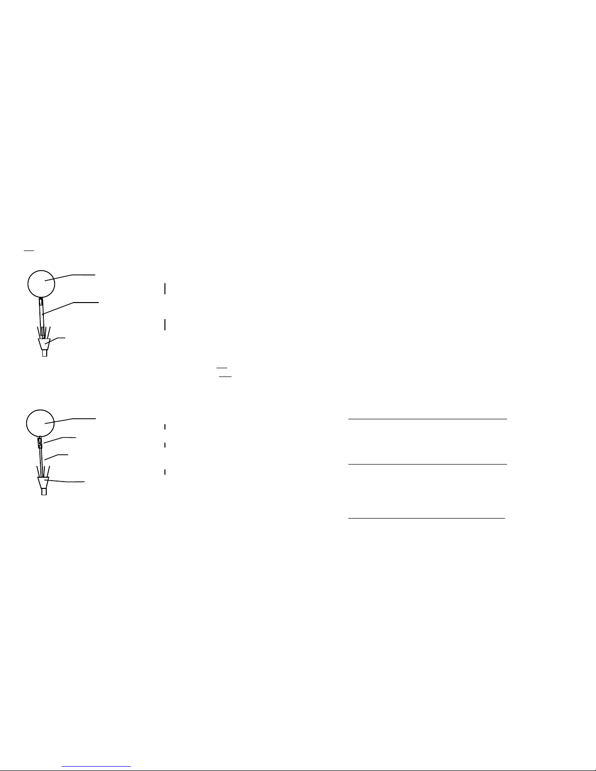
Valve Cables
One problem that is easy to diagnose and x is a broken cable connection.
Use any ohmmeter to measure the resistance across the inner pin and
outer ‘barrel’ of the RCA plug end of the valve cable (while unplugged
from the controller.) A resistance of zero ohms indicates a short, or innite
resistance means one of the wires is broken in the cable assembly. This
occurs most often at the joint between the heavy black cable and the valve
lead wires – under the heat-shrink tubing, inside the outer black sheath,
a few inches from the valve itself. This can often be reached without
completely disassembling the valve enclosure.
Simply 1) remove the screw inside the black valve box holding the plastic
sheath in its hole, 2) remove the black tape at the top of the sheath and
peel it back a couple of inches, nd the oending cable (trace it back from
the bad valve), and 3) carefully slice its heat-shrink tubing longitudinally
to remove it. The wires may
have come apart or broken
here, or inside the next piece of
electrical tape isolating the two
leads, otherwise within the cable
or valve itself (which can be
1
2
Valve enclosure (shown without front plate)
Plastic ‘split loom’ cable sheath.
37
36
Page 21

further determined with the volt/ohmmeter). If you nd
the break, resolder the connection, wrap the inner wires
in separate pieces of electrical tape, retest the valve, and
reassemble the sheath following the above instructions in
reverse order.
Valve Returns & Replacing a Valve
If you need to return a defective valve, you may either return the
entire valve assembly for repair / evaluation, or remove and return the
individual valve from its case. This only involves ve screws: remove the
two outer plate screws holding all of the valves into the black metal case,
the single screw holding the plastic ‘sheath’ into its underside hole, the
electrical tape at the top and bottom of the sheath, the oending valve’s
cable from the plug end up through the valve casing, and nally, the two
screws holding the valve on to the front plate.
Please package the valve(s) carefully and ship freight prepaid to AutoMate
Scientic’s address on the back cover of this manual. No RMA number is
needed as long as you include a note with the following:
1) Your name, company/institution name, phone number, and an address
to return the repaired valve to.
2) Your original invoice number and date, if available.
3) A sentence stating the nature of the problem and any steps you have
already taken to x or identify it. Does the valve energize / click? Deenergize? Open / close? Leak?
4) Whether the valve was driven by any device other than an AutoMate
Scientic controller (and its operating and holding voltages).
5) The application used with the valve, along with the exact chemical(s)
and the duty cycle (pulse) rate if used.
6) A Statement of Chemical Exposure as follows:
a) These valves have not been exposed to chemicals other than H2O
except as described above. b) All applicable Safety and Handling data
sheets for the above described chemicals are enclosed. c) We accept
full responsibility for any injury to AutoMate Scientic employees or
employees of the valves original manufacturer caused by handling of
the residues of chemicals contained in or on the valves to be returned.
7) An authorized signature, title, and date.
AutoMate Scientic will gladly fax you a form with easy blanks to enter
the above information. We will process your return and notify you of
further information as quickly as possible.
3
Heat
shrink
on each
cable
Leaks and Replacing Valve Fittings
The second bane of all liquid delivery apparatus! These hints may help:
1) Make sure the valve is turned o! (as opposed to leaking)
2) See all of the guidelines in the previous “Faulty Valves” section -
especially #1.
3) Identify whether the valve leaks constantly, under pressure, inside or
outside. Try backushing if there is an internal leak.
4) Check and replace obvious loose or worn tubing.
5) Outside leaks usually occur at the ttings and can be stopped with a bit
of silicone glue, epoxy, super glue (Cyanoacrylate) or PTFE tape. Apply
sealant around the threads of the dry tting and screw back into the
valve. Be sure not to use too much glue or tape, as they can easily cause
clogs or leaks of their own. Overtightening can also cause the plastic
ttings to leak – hand tighten.
Glue on valve ttings is intended as a gap ller for small openings between
the threads and hole, not as an adhesive. Few glues will adhere to PTFE.
Hardware Troubleshooting
Should the ValveLink8.2's LEDs fail to light while plugged-in, check the
power connections. Disconnect all valves to check for a short. Remember
that ValveLink8.2 valve LEDs do not light if valves are not plugged-in.
The ValveLink8.2 uses an internal "poly" fuse which will reset itself after an
overload situation has been xed. Try unplugging the ValveLink8.2 for a
while then reconnecting it.
39
38
Page 22

Safety Instructions
The following instructions pertain to the risk of re, electric shock, or bodily injury.
Please read all of these instructions carefully.
1. Follow all the instructions and warnings marked on this product or included in
this manual.
2. Do not use this product on an unstable cart, stand, or table. This product may fall,
causing serious damage to the product.
3. Slots and openings in the cabinet are provided for ventilation. To ensure the
reliable operation of your product, and to protect it from overheating, these openings
must not be blocked or covered. Do not use this product on a bed, sofa, rug or other
similar surfaces. This product should never be placed near or over a radiator or heat
register. This product should not be placed in a built-in installation unless proper
ventilation is provided.
4. Never push objects of any kind into the product through the cabinet openings, as
they may touch dangerous voltage points or short-out parts that could result in re
or electric shock. Never spill liquids of any kind in the product.
5. This product should only be connected to the AC power source indicated on your
product system’s information label. If you are not sure of the type of AC power
available, consult your dealer or local power company. Only connect this product to
a power outlet that matches the power requirements of this product.
6. Do not allow anything to rest on the power cord. Do not locate this product where
people will walk on the cord.
7. If you have to use an extension cord with this product, make sure that the total
amperage rating of all equipment plugged into it does not exceed the amperage rating
of the extension cord. Also, make sure that the total of all products plugged into the
main AC power outlet does not exceed 15 amps.
8. Unplug your product from the main electrical power before cleaning. Do not use
liquid cleaner or aerosol cleaners. Use a damp cloth for cleaning.
9. Do not use this product near water.
10. Unplug this product from the main power outlet and call for service under any
of the following conditions:
A. If the power cord or plug is damaged or frayed.
B. If liquid has been spilled into the product.
C. If the product has been exposed to rain or water.
D. If the product has been dropped or the cabinet has been damaged.
E. If the product exhibits a distinct change in performance, indicating a need for
service.
STOP!!
If you ever have to remove the main system unit cover, observe the following
precautions:
A. The power supply cord must be unplugged before the main system unit cover is
removed. (Separe le cordon d’alimantation et puis enleve le couvercle.)
B. Once removed, the cover must be replaced and screwed in position before the
power supply is plugged back in. (Apres le couvercle en place et remettre le cordon
d’alimentation.)
41
40
Page 23

Warranty
AutoMate Scientic, Inc. warrants its products against defects of
workmanship and/or material for ONE YEAR from the date of sale. Any
product that fails to perform as specied may be returned, freight pre-paid
to the factory (with a written explanation of the problem) for examination
and repair or replacement. If it is defective, AutoMate Scientic will repair
or replace (at our option) the product without charge and return it to you.
If the examination indicates that non-compatible uid, destructive
environment, accidental damage, modication or abusive practices have
occurred, all labor, materials and freight costs shall be at the expense of the
customer.
Due to the nature of clinical laboratory applications, AutoMate Scientic,
Inc. will NOT accept the return of any products which have been used with
HAZARDOUS MATERIALS or harmful environment.
This warranty is in lieu of all other warranties, whether oral or written,
express or implied. In no event shall AutoMate Scientic, Inc. or its
licensor/licensees be liable for contingent, special, direct, indirect or
consequential damages for the breach of any express or implied warranty
or resulting from the use, failure or malfunction of any product, including
damage to property and, to the fullest extent permitted by law, damages
for personal injury, even if AutoMate Scientic, Inc. has been advised
of the possibility of such damages or if this warranty is found to fail its
essential purpose. AutoMate Scientic, Inc’s liability is limited to the
reimbursement of the cost of the product. All other warranties, including,
but not limited to warranties for tness or merchantability for a particular
purpose are expressly excluded. No verbal changes to this policy will be
authorized.
AutoMate Scientic, Inc. manufacturers and sells goods in accordance with
U.S. federal, state and local laws, but assumes no responsibility or liability
for laws, regulations, duties, or taxes imposed by any foreign country. All
terms and conditions hereof shall be governed by the laws of the State of
California.
European CE Technical Representative:
AutoMate Scientic
An der evang. Kirche 2, Bonn 53113, Germany
43
42
Page 24

AutoMate Scientific, Inc.
812 Page St
Berkeley, CA 94710
U.S.A.
(800) 998-MATE
-6283
international (510) 845-6283
fax (510) 280-3795
e-mail info@autom8.com
www http://www.autom8.com
AutoMate Scientific
®
R
E A D Y F O R R E S E A R C H.
TM
 Loading...