


OWNER’S GUIDE
MODEL
3303A
Since its inception, Directed has had one
purpose, to provide consumers with the fin-
est vehicle security and car stereo prod-
ucts and accessories available. The recipient
of nearly 100 patents and Innovations Awards
in the field of advanced electronic technology.
Quality Directed products are sold and ser-
viced throughout North America and around
the world.
Call (800) 274-0200 for more information
about our products and ser vic es.
Vista, CA 92081
Directed is committed to delivering worldclass quality products and services that excite
and delight our customers.
Vehicle Security System
QRG3303A 2012-06
©
2012 Directed. All rights reserved.
www.automatecarsecurity.com

Congratulations
Congratulations on the purchase of your state-of-the-art security and
remote start system. Reading this Owner’s Guide prior to using your
system will help maximize the use of your system and its many features. Please visit: www.automatecarsecurity.com – For general and
additional guide information. For any additional questions please
contact your authorized Directed dealer or contact Directed at 1-800-
753-0600 (U.S. only). Additional support is also available at: http://
support.directed.com.
Additional Guide Information
Only basic commands, features and essential information are covered
in this compact guide. Your product has many advanced features
which are not discussed here, please consult the expanded online
version for these at: www.automatecarsecurity.com. Most sections in
this guide also contain additional information which can be found in
the expanded online version.
What you get
Welcome to the best generation of vehicle security. Your system contains everything you need.
s LCD remote control, 2-way with Supercode technology for supe-
rior range and reliability (p/n 7351A)
s Companion remote control, 1-way (p/n 7143A)
s AC adapter for charging your remote control

Government Regulations and Safety information
Read the Government Regulations and Warning! Safety
First sections of this manual prior to operating this system.
Warning! Failure to heed this information can result in
death, personal injury or property damage and may also
result in the illegal use of the system beyond its intended
purpose.
Your Warranty
Your system comes with a warranty. Make sure you receive the warranty registration card and proof of purchase from your dealer indicating the product was installed by an authorized Directed dealer. Please
validate it online at www.prodregister.com/automate or complete
and return the warranty registration card.
Getting Started
Due to transit and storage time prior to your purchase, the battery
charge may have depleted. To ensure proper operation, check the
battery level and connect the battery charger if not fully charged.
Charging the remote control:
1. Plug the AC adapter into a 110V AC outlet. Insert the miniUSB connector into the mini-USB port located on the side of
the remote control. The text field displays
CHARGE
to indicate
the remote control is charging (The remote remains operational
while charging and can command the system).
2. Once fully charged the text field displays
FULL
.

Contents
Government Regulations and Safety information ................................................... 2
Responder LC 2-Way........................................................................................... 2
Status Screen Icons .............................................................................................. 4
Using your System ............................................................................................... 7
Commands and Confirmations .............................................................. 7
Performing Commands ......................................................................... 7
Responder LC Command table .............................................................. 8
Basic Commands (Direct Access) .......................................................................... 9
Arm ................................................................................................... 9
Disarm ............................................................................................... 9
AUX/Trunk ........................................................................................ 10
Remote Start /AUX 1/ AUX 4 ............................................................. 10
Advanced Commands: (Level 1) ......................................................................... 11
Silent Arm ......................................................................................... 11
AUX 1 .............................................................................................. 11
Advanced Commands: (Level 2) ......................................................................... 12
Sensor Bypass ................................................................................... 12
Remote Valet .................................................................................... 12
AUX 2 .............................................................................................. 12
Advanced Commands: (Level 3) ......................................................................... 13
Sensor Silent Arm .............................................................................. 13
AUX 3 .............................................................................................. 13
Alarm Report ..................................................................................... 14
Advanced Commands: (Level 4) ......................................................................... 15
Full Silent Arm ................................................................................... 15
AUX 4 .............................................................................................. 15
1-way Companion Remote Control .....................................................................16
Battery Information (Responder LC) ..................................................................... 17
Battery Information (1-Way) ................................................................ 17
Battery Disposal ................................................................................ 17
Patent Information ............................................................................................. 18
Government Regulations .................................................................................... 19
Additional information ....................................................................................... 20
Interference ....................................................................................... 20
Upgrades and Batteries ...................................................................... 20
Water/Heat Resistance ...................................................................... 20
Limited lifetime consumer warranty ..................................................................... 21
2
© 2012 Directed. All rights reserved.
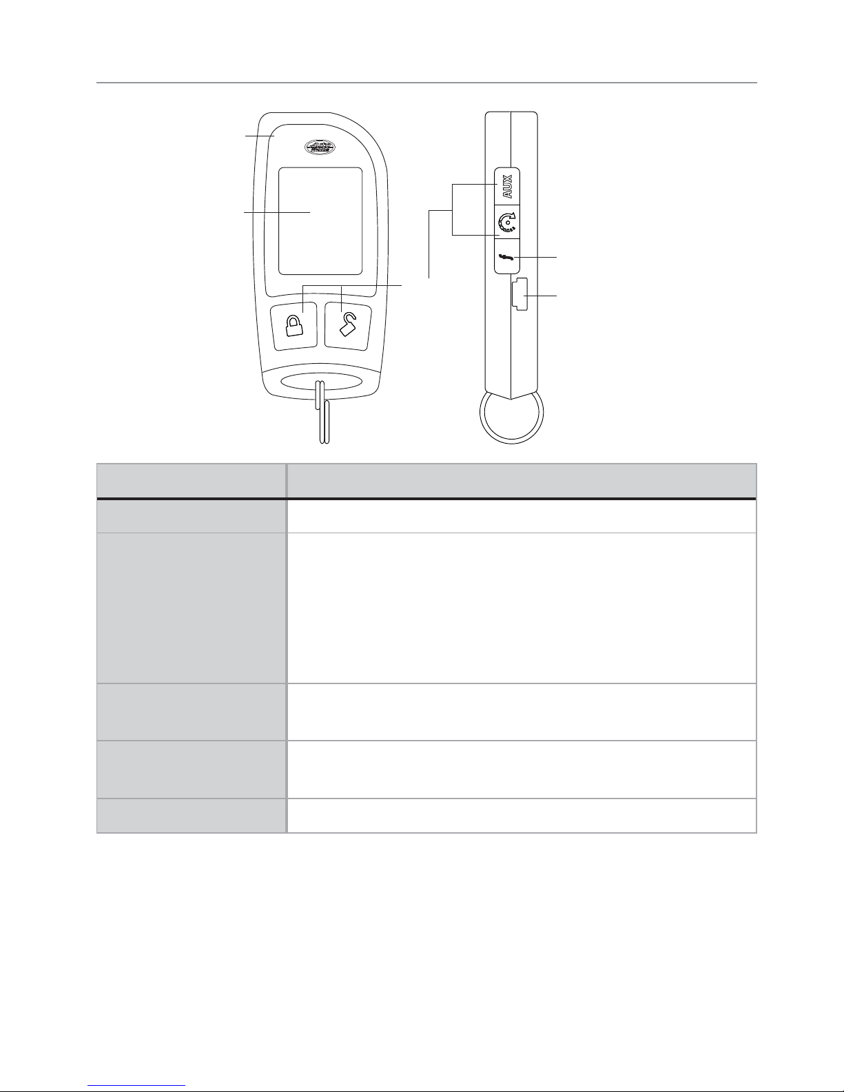
Responder LC 2-Way
Command
Buttons
Display
Function Button
Mini-USB Port
Internal
Antenna
Feature Description
Internal Antenna Used for transmitting and receiving information
Display Status screen - the upper portion of the display contains status
icons for the system, siren, alarm zones, and remote control
Text field - the lower portion of display shows the clock,
command confirmations, page messages and programming
menus
Command Buttons (4) Used to perform arming, disarming and auxiliary channel
commands
Function Button Used to access function levels for commands, configuration
menus for programming, and car selection
Mini-USB Port The battery charger plugs into this port

3
© 2012 Directed. All rights reserved.
Control Center
Control button
Status LED
The control center, typically located on the upper part of the front
windshield sends and receives commands or messages to and from
your system. It consists of:
s The In-vehicle system antenna, for 2 way communication.
s The Status LED, as a visual indicator of the system’s status.
s The Control button, for placing the system into valet mode* and
to perform the emergency override** operation.
* See Remote and System Operations in online guide.
** See Alarm Features in online guide.
4
© 2012 Directed. All rights reserved.
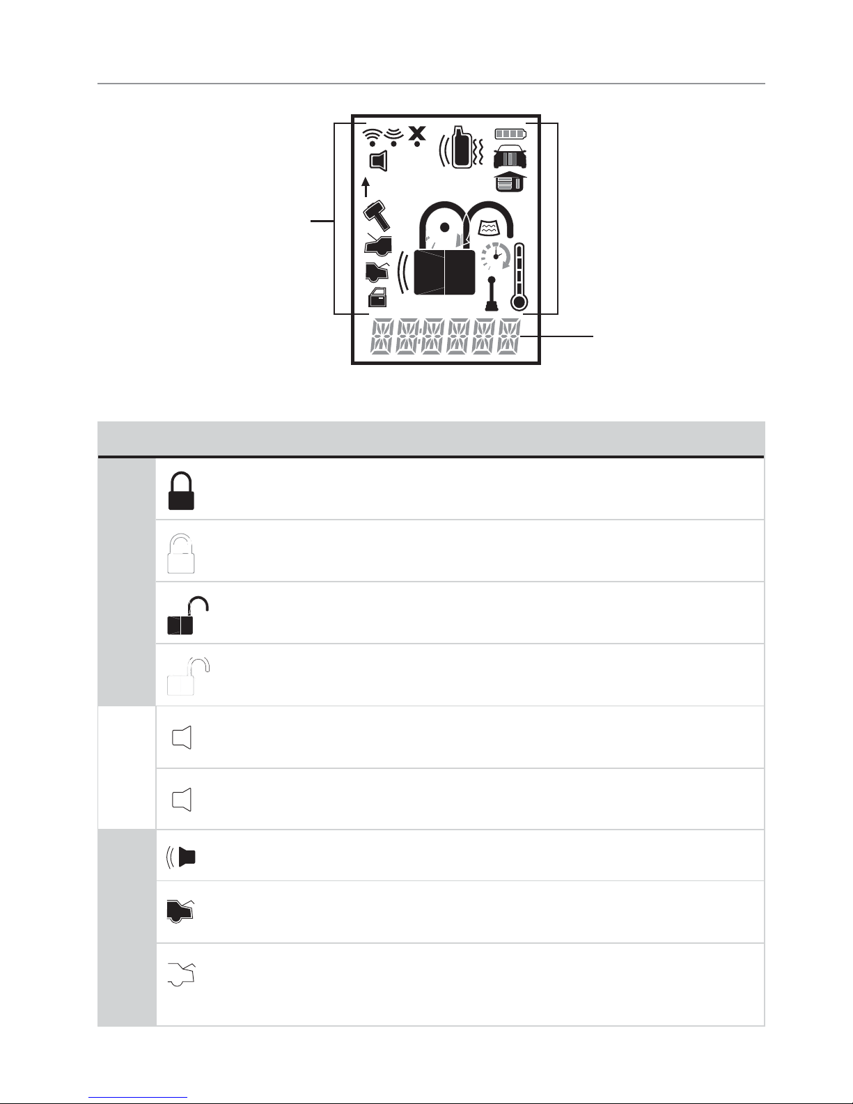
Status Screen Icons
1
ALL
Text Field
Status Screen
Icons
The table below describes all the status screen icons.
Icon Description
System Status
Armed: The system is armed, the alarm is enabled
Locked: The system is locked in valet, the alarm is disabled
Disarmed: The system is disarmed, the alarm is disabled
Unlocked: The system is unlocked in valet, the alarm is disabled
Siren Status
Siren is disabled for sensor triggers; remote is paged for all triggers (sensor silent arm)
+ ALL
Siren is disabled for all triggers; remote is paged for all triggers
(full silent arm)
Zone Status
On during warn-away and full trigger message output
On during trunk zone full trigger output and aux/trunk channel
activation
On during fault report to indicate the trunk is open and
bypassed when arming

5
© 2012 Directed. All rights reserved.
Icon Description
Zone Status
On during a sensor zone full trigger output
On during fault report to indicate a sensor is active and
bypassed when arming
On during the door zone full trigger output
On during fault report to indicate a door is open and bypassed
when arming
On during a hood zone full trigger output
On during fault report to indicate the hood is open and
bypassed when arming
On when remote is set to command the system programmed
as car 1*
On when remote is set to command the system programmed
as car 2*
Remote Control Status
Bars indicate battery level is full, ¾,½,¼ or empty
On while the remote control is transmitting a command
On while the remote control is receiving a message
On with out of range fault tone to indicate the remote failed to
receive a command confirmation
Pager on: The remote will wake up to listen for messages
Pager off: The remote will not wake up to listen for messages
The remote will vibrate when messages are received
The remote will emit beeps and tones when messages are
received
 Loading...