

Page 1
Part# 1100268
User’s Manual
DCU 410 Engine Control Unit
RP 410 Remote Panel
Page 2

Page 3

Table of Content
General ...................................................................................................................... 3
About this Manual .............................................................. 3
Marine Pro Overview .......................................................... 4
Available Modules ................................................................... 4
DCU 410 Operation............................................................................................ 6
Overview ........................................................................... 6
Buttons ................................................................................... 6
Screen Layout ......................................................................... 6
Screen Navigation ................................................................... 7
Start and Stop Engine ......................................................... 7
Start Engine ............................................................................ 7
Stop Engine ............................................................................ 7
Alarm List .......................................................................... 8
Enter the Alarm List ................................................................ 8
New Alarms ............................................................................ 8
Filter Alarms ........................................................................... 9
Silence the Buzzer ................................................................... 9
Acknowledge Alarms .............................................................. 9
Softbuttons ...................................................................... 10
Quick Access ........................................................................ 10
The Menu ........................................................................ 11
Settings ................................................................................ 11
Counters ............................................................................... 12
Generator ............................................................................. 14
Display ................................................................................. 14
Language .............................................................................. 14
Configuration ....................................................................... 15
Help ...................................................................................... 18
Symbols and Indication Icons ........................................... 21
RP 410 Operation ............................................................................................. 22
Overview ......................................................................... 22
Buttons ................................................................................. 22
Screen Layout ....................................................................... 22
Start and Stop Engines ..................................................... 24
Start Engine(s) ...................................................................... 24
Stop Engine(s) ....................................................................... 25
Alarm List ........................................................................ 26
Enter the Alarm List .............................................................. 26
Silence the Buzzer ................................................................. 26
Acknowledge Alarms ............................................................ 26
The Star in the Alarm List ...................................................... 27
Filter Alarms ......................................................................... 27
Page 4

Home Button ................................................................... 28
The Menu ........................................................................ 29
Menu selections .................................................................... 29
Configuration selections ....................................................... 33
Symbols and Indication Icons ........................................... 36
Local mode – L ...................................................................... 36
Manual mode – M .................................................................. 36
Shutdown Override – SO ........................................................ 36
Service and Diagnostics – wrench symbol .............................. 36
Active Station symbol ............................................................ 36
Active Station – star symbol .................................................. 37
Warning and Alarm Triangles ................................................ 37
DCU and RP Common .................................................................................... 38
Alarm List colors explained ................................................... 38
P a g e | 2 Marine Pro User's Manual
Page 5

General
About this Manual
This manual has been published primarily for
professionals and qualified personnel. The user of this
material is assumed to have basic knowledge in marine
systems.
Note! Auto-Maskin continuously upgrades its products
and reserves the right to make changes and
improvements without prior notice.
All information in this manual is based upon information
at the time of printing.
For updated information, please contact your local
distributor.
Valid Versions
This User’s Manual is valid for the following firmware
releases of the DCU and RP.
Panel Firmware Release Date
DCU 410
RP 410 1.4 October 2009
1.4 October 2009
Manual Revisions
Title: Marine Pro User's Manual
Printed: October 2009
Revision:
Copyrights and Trademarks
Copyright © Auto-Maskin AS, 2009
Information given in this document may change without
prior notice. This document should not be copied without
written permission from Auto-Maskin.
All trademarks acknowledged.
Marine Pro User's Manual P a g e | 3
Page 6

Marine Pro Overview
Available Modules
The following modules are available in Marine Pro
• DCU 410 Engine Monitoring and Control Unit
• DCU 408 Engine Control Unit; no user interface
• SDU 410 Safety Unit
• RIO 410 I/O Expansion Unit
• RIO 425 Generator Interface Unit
• RP 410 Remote Panel Unit
The following is a brief explanation of the different
modules.
DCU 410 and DCU 408 Engine Control Units
DCU 410 and DCU 408 (hereafter referred to as the
“DCU”) are the engine monitoring and control units. One
panel is required for each engine. The DCU 410 has a
color screen and buttons for user interaction. The DCU
408 is the low cost version without a user interface,
intended for use with remote panels.
Note! The DCU 410 and DCU 408 will hereafter be
referred to as the “DCU” only. If functionality differs
between the two, this will be noted.
SDU 410 Safety Unit
The SDU 410 is the safety module, and is linked to the
DCU engine control unit. It is mandatory in classed
installations that are to be type approved.
RIO 410 I/O Expansion Unit
The RIO 410 is an I/O expansion unit, and is linked to the
DCU, which will find it automatically.
P a g e | 4 Marine Pro User's Manual
Page 7
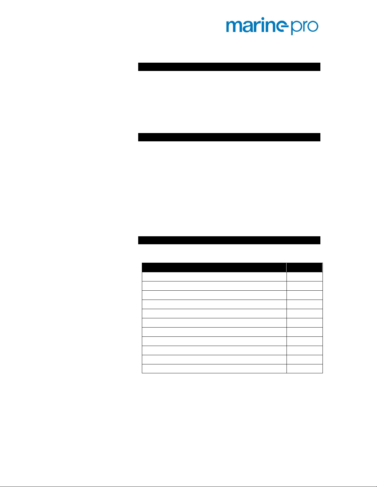
A maximum of four RIO units can be connected to one
DCU.
RIO 425 Generator Interface Unit
The RIO 425 is a generator interface unit. It is linked to
the DCU, which will find it automatically.
When connected, a new page is made available on the
DCU – and on the remote panel RP 410 – that displays
generator parameters such as phase voltages, phase
currents, frequency, power, efficiency factor (Cos phi),
etc.
RP 410 Remote Panel
The RP 410 is the remote panel for the DCU engine
panels.
Numerous RP remote panels can be connected together in
the same Ethernet network.
Ordering Information
The following parts are available in Marine Pro.
Item Part #
DCU 410 Engine Control Unit 1006450
DCU 408 Engine Control Unit 1006455
RIO 410 I/O Expansion Unit 1006453
RIO 425 Generator Interface Unit 1006457
SDU 410 Safety Unit 1006451
RP 410 Remote Panel Unit 1006452
MK-14 Relay Expansion 1121341
Ethernet Switch, 5 channels, 24V supply, DIN-rail 1050165
CANbus communication cable 1009110
CANbus/Fiber converter 1121268
IP Camera 1121258
Marine Pro User's Manual P a g e | 5
Page 8

DCU 410 Operation
Overview
Buttons
Screen Layout
The DCU has buttons for the following:
• Start engine
• Stop engine
• Alarm List
• Menu
• Arrow up and down
• Four soft buttons, with varying functionality
The screen is divided into three main sections:
• Status bar Top most line on the screen, which is
reserved for engine state and status symbols.
• Soft button line Bottom most line on the screen,
which is reserved for soft buttons, which have
varying functionality depending on the selected
screen.
P a g e | 6 Marine Pro User's Manual
Page 9

• Main screen area This is where all instruments
and menu items are displayed.
Screen Navigation
The DCU can have multiple instrument
screens. Press the arrow buttons to navigate
between them.
If there is one instrument screen only,
pressing the buttons will not change the
screen.
Pressing the same button repeatedly will
eventually scroll around to the same screens.
Start and Stop Engine
Start Engine
The start button can be configured as latched or hold. It
will always be the same as the stop button, though.
If the button is configured as latched, press the start
button, observe the confirmation dialog, and press Yes to
start. The DCU will complete the start sequence.
If the start button is configured as hold, press and hold
the start button until the engine has started.
Stop Engine
The stop button can be configured as latched or hold. It
will always be the same as the start button, though.
Marine Pro User's Manual P a g e | 7
Page 10

Alarm List
If the button is configured as latched, press the stop
button, observe the confirmation dialog, and press Yes to
stop. The DCU will complete the stop sequence.
If the stop button is configured as hold, press and hold
the stop button until the engine has stopped.
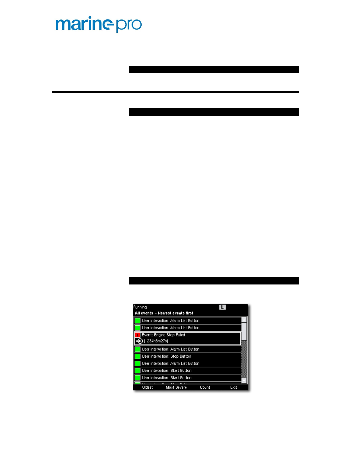
Enter the Alarm List
New Alarms
To see the alarm list, press the alarm list button.
Press the button again to leave the alarm list. Or, press
the Exit button.
New alarms are displayed in bold text. Above, the alarm
Engine Stop Failed is new. The alarm is Unacknowledged.
Once the alarm is acknowledged, the alarm text is no
longer bold.
Note! For more information on the alarm list, please see
page 38.
P a g e | 8 Marine Pro User's Manual
Page 11

Filter Alarms
Silence the Buzzer
The alarm list can filter alarms in three groups
• All Alarms (all alarms and diagnostics)
• Panel Alarms (all alarms, no diagnostics)
• Diagnostics (diagnostics only)
To switch between the different views, press the
corresponding softbutton 2 and/or softbutton 3.
If the buzzer sounds, press the alarm list
button to silence the buzzer.
• If not already in the alarm list, this
operation will display the alarm list.
• If already in the alarm list when the buzzer sounds,
then pressing the alarm list button to silence the
buzzer will not exit the alarm list, but only silence
the buzzer.
Acknowledge Alarms
Acknowledge a single alarm
Acknowledge all alarms
• In the alarm list, select the alarm to acknowledge
using the arrow buttons. The selected alarm line
will expand to reveal additional information, if any.
• Press the Acknowledge button to acknowledge the
selected alarm.
• In the alarm list, press and hold (1 sec) the
Acknowledge button. This acknowledges all
alarms.
Marine Pro User's Manual P a g e | 9
Page 12

Note
screen until they go inactive.
Softbuttons
The DCU has four
A softbutton is a regular button, which changes function
depending on the screen context.
These
picture below.
There are four functions assigned to the soft buttons in
instrument view.
These
menu.
larms that are still active will stay displayed in the
located directly under the screen
(speech symbol)
Local/Remote
through the
Quick Access
! A
softbuttons.
buttons are
These are:
• Soft button 1: Language
• Soft button 2: Backlight
• Soft button 3: Units – Metric or U.S.
• Soft button 4: Operation –
four functions are also available
; see
main
Page 13
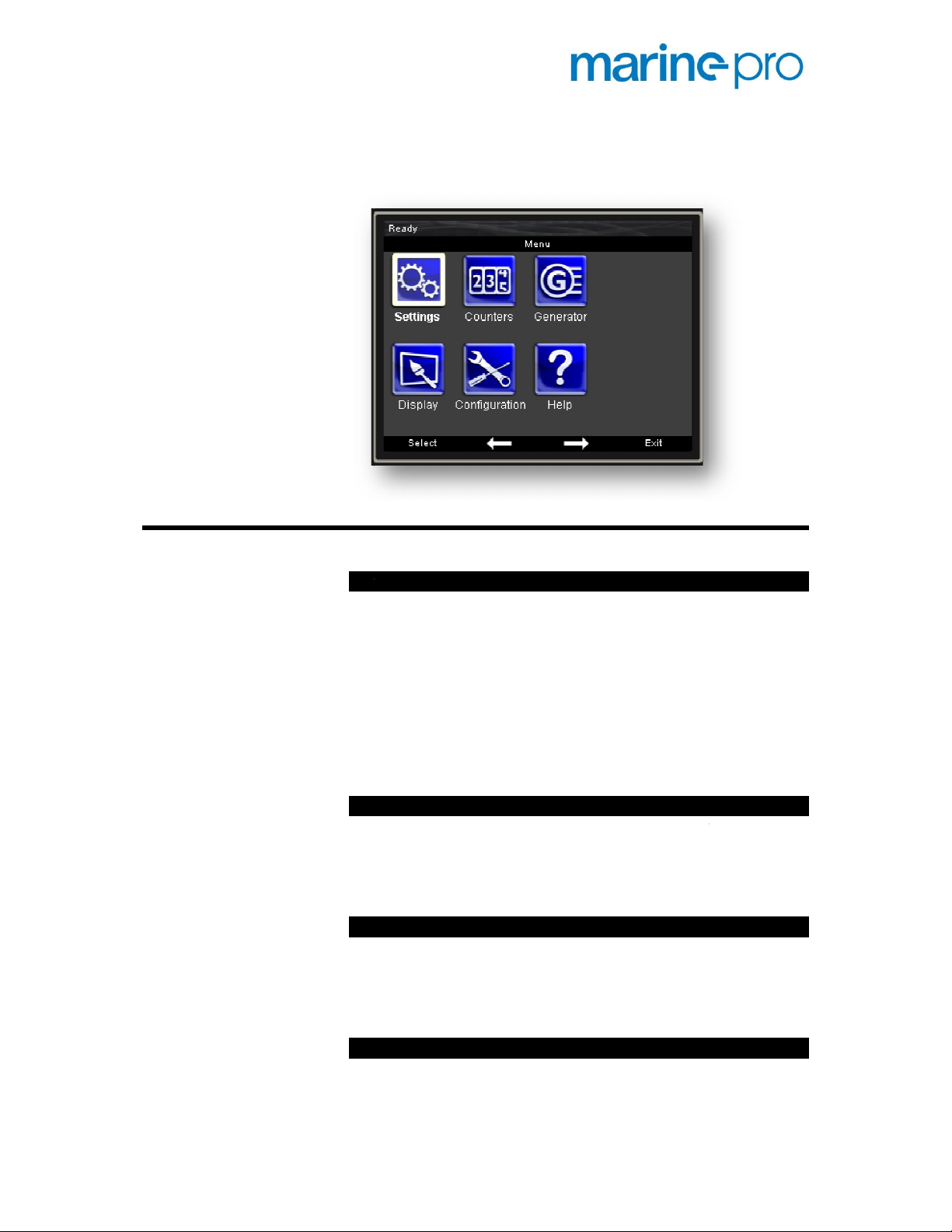
The Menu
The following chapters explain each menu item.
Automatic/Manual
When set to Automatic, the DCU will do automatic start
and stop from a remote signal, e.g. a power management
system.
In Manual, the DCU will NOT do automatic start and stop.
In Manual, the symbol
Note
a Manual setting in the menu.
The rule is: If either the menu
comm
Local/Remote
In Local mode, the DCU cannot be operated from remote,
and an
Neither communication commands, nor hardwired
commands will work in Local mode.
Start Disabled
Select
remote, on this engine.
Note
connection before any maintenance work on the engine.
Prelube Override
If the engine is normally configured to prelube the engine
before start, this can be cancelled or aborted.
is visible in the status bar.
The DCU terminal 88 (Automatic Mode) will override
the remote signal
Start Disabled to disable all starts, local and
It is recommended to remove the start battery
Settings
M
!
or
ands Automatic, then it is Automatic.
L
symbol is visible in the status bar.
!
Page 14
Counters
If selecting Prelube Override during a prelube sequence,
the prelube will be aborted and the DCU will continue to
crank the engine.
Button Beep
Select whether a button press shall beep the buzzer.
Counters
The counters page keeps the engine running hours
counters.
Total
The total accumulated engine hours. Depending on the
configuration, the value is calculated in the DCU, or read
from the ECM.
This counter value cannot be reset by the operator.
Since Start
This counter starts at zero every time the engine is
started, and counts until the engine is stopped.
This counter value cannot be reset by the operator.
Since Reset
This counter accumulates every time the engine is
running.
Press the Reset button to zero the values since last reset.
Event Log
The DCU keeps a log of all events. The log is about 500
events long, after which the oldest event is lost.
An event is any diagnostic, warning alarm or engine
shutdown situation, but also button presses.
P a g e | 12 Marine Pro User's Manual
Page 15

Event Sorting
The events can be sorted as follows:
•
Oldest first
•
Most severe first
•
Least severe first
•
Count
Navigation
Use the up and down arrow to navigate in the event log.
Timestamp
The selected event will be expanded, and the second line
displays the running hours for when the event happened.
For alarms, the second line will also display the running
hours for an acknowledged and inactive situation.
Engine Service Interval
The DCU can be configured to indicate service from up to
four different service counters.
All counters have a predefined hour counter interval, and
count engine running hours.
Service Due
A due service is indicated with a wrench key, and is
indicated in the alarm list (no audible indication).
Service Done
When service is done, select this menu item and press
Service Done to restart the counter for a new service
interval.
Marine Pro User's Manual P a g e | 13
Page 16

Generator
If the DCU engine panel is connected to an optional RIO
425 unit
generator symbol is displayed here. Selecting it displays
the generator values on a new page.
Note!
the up or down button from the normal instrument view.
Screen Backlight
Select between different screen backlight settings.
Units
Select units
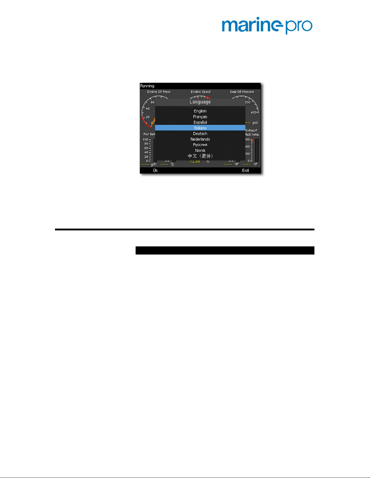
Select any panel language from one of the following
languages:
to read generator parameters, then the
This page can also be accessed by simply pressing
Automatic varies between 10 and 100% using an
Display
Language
•
10% backlight is as dark as it can be
•
50% backlight is half full
•
100% backlight is fully lit
•
ambient light detector.
•
Metric (Celsius, bar, etc), or
•
U.S. (Fahrenheit, psi, etc)
•
English
•
French
•
Spanish
•
Italian
Page 17
•
German
•
Dutch
•
Russian
•
Norwegian
•
Chinese
Note!
Texts for configured instruments must be
translated manually during installation.
If a language is selected for which there is no such
manual translation, the default language will be used.
Configuration
Engine Overspeed Test
In this mode, the engine can be tested for overspeed by
lowering the overspeed setpoint to nominal speed.
Overspeed Test sequence
•
Make sure the engine is not running. The
Overspeed Test mode cannot be entered on a
running engine.
•
Observe that the overspeed setpoint has been
lowered by observing the red are on the RPM
meter.
•
Start the engine and adjust rpm until it crosses the
red labeled setpoint.
•
Observe engine shutdown.
Overspeed Test Off
The Overspeed Test times out after 5 minutes, or when an
actual overspeed situation is observed.
The test can also be turned off by selecting the menu
item again.
Marine Pro User's Manual P a g e | 15
Page 18

Connect a PC
Often, the IP address in a laptop PC is locked due to
company policy, and can only be set dynamically
(changed) by a DHCP server when connected in a network.
For this purpose, the DCU has an inbuilt DHCP server,
which may be activated in order to issue a new IP address
to the laptop.
At the top of this form, the current IP number in the DCU
is listed. The next lines display a start and end IP address.
This is the range the DHCP server will scan.
Make sure the DCU IP address is outside the DHCP
address range by setting the start IP higher or the end IP
lower than the DCU IP number. For instance will end IP
192.168.0.110 be OK, whilst end IP 192.168.0.140 will
not be OK for the example shown in the figure.
Press Save. The DCU’s DHCP server will now issue a
dynamic IP address to any laptop connected to the DCU
within the next 10 minutes. The laptop keeps the issued
IP address even after the 10 minute timeout.
If the DCU is connected to a local area network (LAN)
serving more equipment, the help of staff running the
LAN may be needed as one should not run several DHCP
servers in the same LAN. Also in this case, the IP address
of the DCU should be set according to the address range
of the LAN.
Configuration
This is where sensor parameters on the DCU are
configured.
The section is password protected, and is not the scope in
this manual. Please see the Marine Pro Installation
Manual.
Interface Design
Up to four extra instrument screens can be added by the
user.
P a g e | 16 Marine Pro User's Manual
Page 19
Note!
Make sure you know what you do – and what to do
– before attempting this chapter.
Note!
Normally, such screens would only be added by the
engine supplier, then using the web interface
programming tool.
Understanding the screen layout
The screen is made up of
Templates, Slots
and
Widgets
like this:
Widget Slot Template Screen.
•
The
Widget
is the instrument. It can for instance
be a circular dial or a horizontal bar.
•
The
Slot
is the placeholder for the Widget. Not all
Widgets fit in all Slots.
•
The
Template
defines where the Slots are on the
screen.
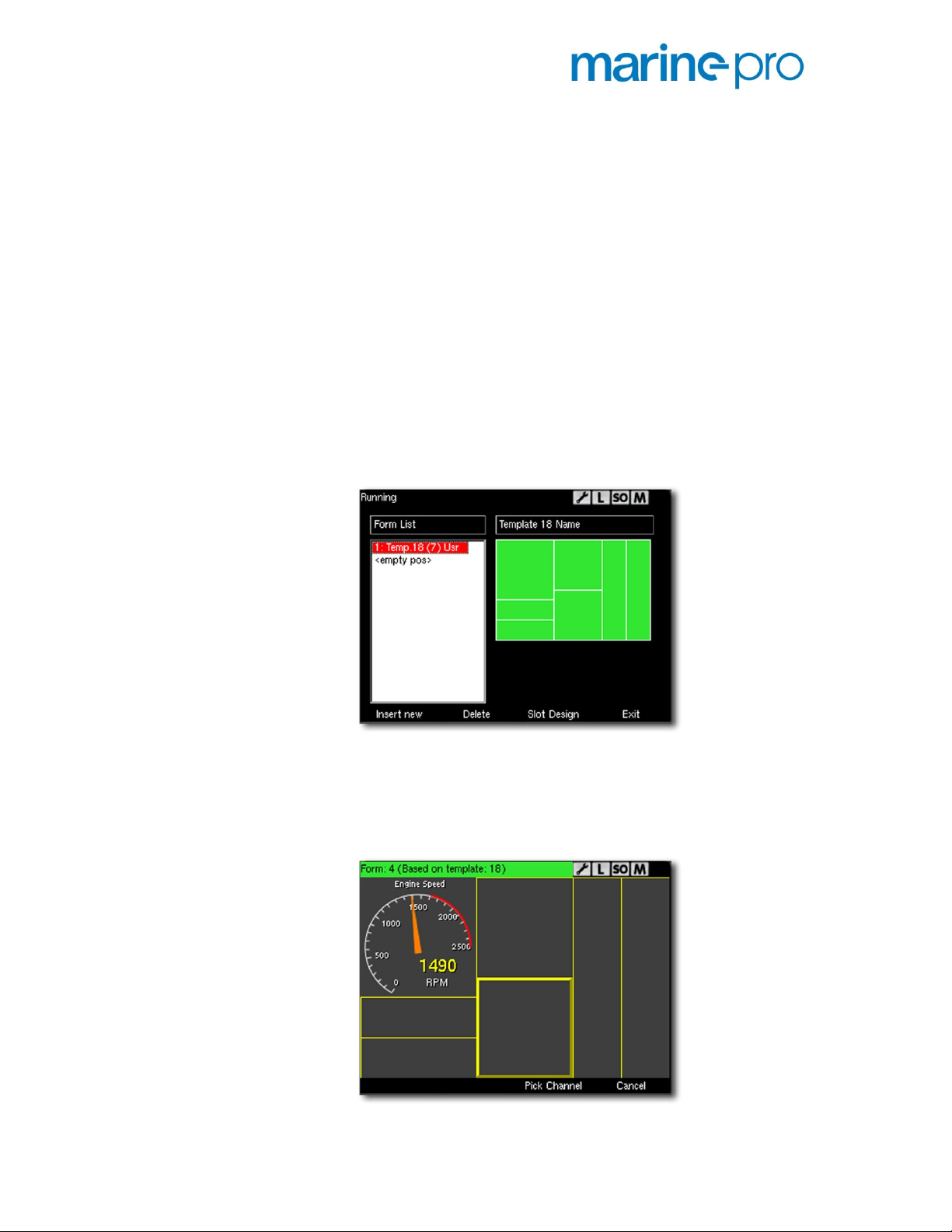
Add a user screen
1. Press Insert new. Use the up/down arrow buttons
to select a suitable template. Press OK, and then
Save.
2. Now, press Slot Design.
3. Press Edit View.
Marine Pro User's Manual P a g e | 17
Page 20

4. Use the arrow buttons to select a slot (indicated
with a bold rectangle around it), then press Pick
Channel.
5. Using the arrow buttons, pick any signal from the
list, then press Select.
6. Do step 3 again until all slots are populated.
7. Press Exit.
8. Observe the new screen just being made. Press the
arrow buttons to cycle between screens.
Delete a user screen
1. Use the arrow buttons to select the user screen.
2. Press Delete to delete the screen.
Help
Troubleshooting
The DCU has a comprehensive set of troubleshooting
screens for the DCU, and also for each of the optional RIO
expansion units. The following covers the DCU only.
P a g e | 18 Marine Pro User's Manual
Page 21
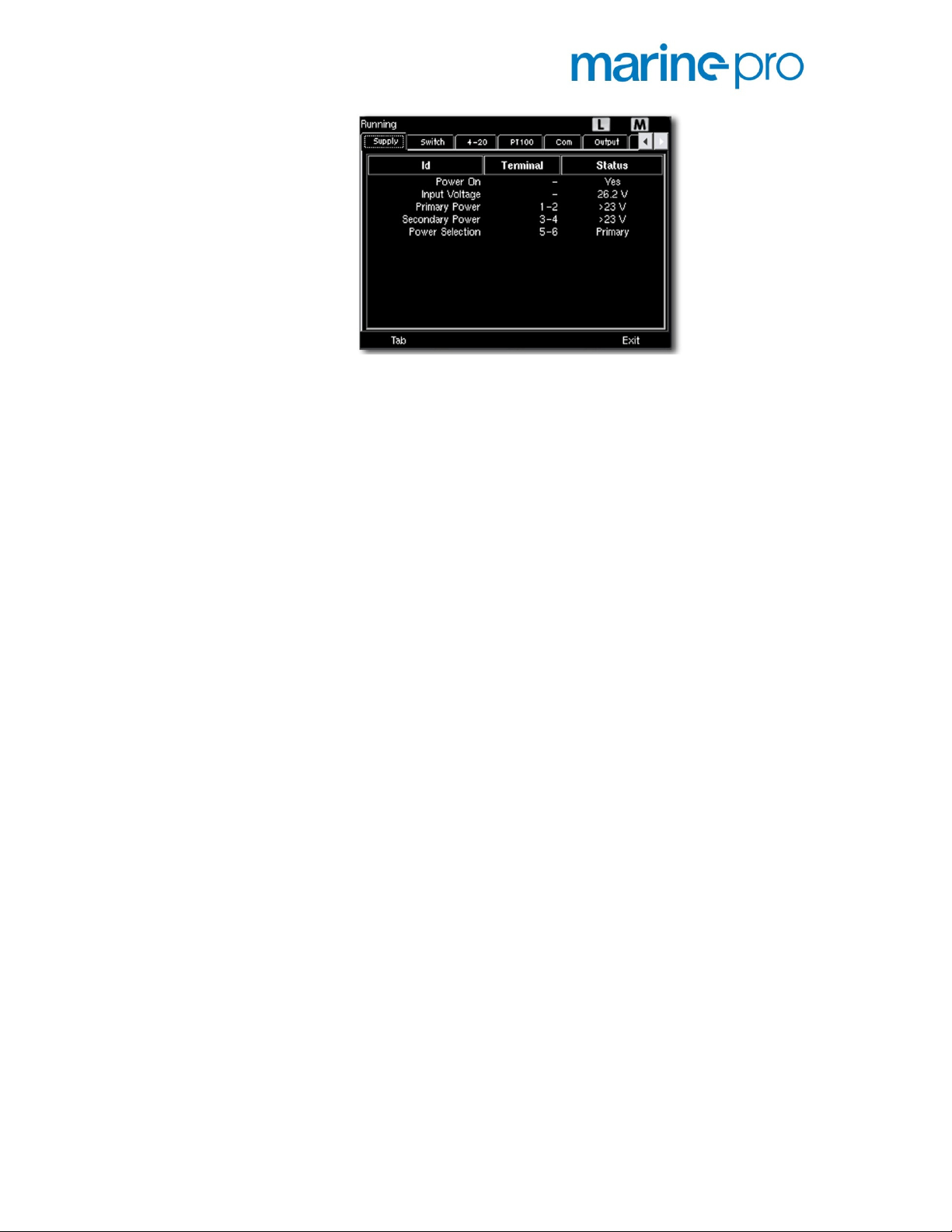
The Troubleshooting screen displaying the Supply section.
Supply
The two power supplies are listed, with information about
voltage and supply selection.
Switch
For each of the eight switch channels, this section
indicates if the switch is open (0V) or closed (24V input).
If for instance the troubleshooting screen indicates open,
and there is a 24V signal connected to the input channel,
then the channel is broken.
4-20mA
For each of the four 4-20mA channels, there is an
indication of:
•
Current, 2-25mA, indicated in mA
•
Broken wire (<2mA)
•
Short circuit (>25mA)
•
Channel in use or not
PT100
For each of the four PT100 channels, there is an
indication of:
•
Value, in Celsius or Fahrenheit
•
Faulty circuit
•
Channel in use or not
COM
This section lists communication status for
communication ports COM 1, 2, 3, 4 and 6.
Output
This lists the output status on DCU terminals 63 to 84.
If for instance terminal 83 indicates Active (24V) and
there is no 24V measured on terminal 83, then that
output is faulty.
Marine Pro User's Manual P a g e | 19
Page 22

Input
This lists the input status on DCU terminal 86 to 97.
If for instance DCU terminal 89 is measured to 24V, but
the troubleshooting screen for that channel indicates
Inactive, then that input is faulty.
Run Indication sources
A number of different sources can be configured to
indicate for the DCU that the engine is running.
This page will reveal which source is giving the DCU a
running engine indication.
Button Test
This section makes it possible to test that all DCU buttons
work.
To leave the test, press and hold soft button 2, then press
soft button 4.
Version Information
Select this to see information about
•
Hardware Version
•
Software Version
•
Connected ECM Version (if any)
•
Own IP number
P a g e | 20 Marine Pro User's Manual
Page 23

Symbols and Indication Icons
The following symbols and icons are available in the DCU
On Instrument Screen
• Yellow
When it flashes above an instrument,
that channel has a new warning.
When the user acknowledges the
warning, the triangle stops flashing.
• Red
When it flashes above an instrument, that channel
has a new alarm, or is responsible for the engine
shutting down.
When the user acknowledges the alarm, the
triangle stops flashing.
triangle is the warning symbol.
triangle is the alarm and/or shutdown symbol.
Status bar
The DCU status bar is the top most line on the screen
•
The L symbol indicates the DCU is in Local mode.
Remote commands are now inhibited.
•
The M symbol indicates the DCU is in Manual
mode. Automatic Start/Stop is now inhibited.
•
The SO symbol indicates the DCU is in Shutdown
Override mode.
•
The green
warning-, alarm-, or shutdown events present in
the alarm list, and also no yellow or red diagnostic
messages.
•
The wrench symbol indicates a service counter is
passed due.
OK
symbol indicates there are no
Marine Pro User's Manual P a g e | 21
Page 24

RP 410 Operation
Overview
Buttons
Screen Layout
The fascia has four buttons with a fixed function for each
button. The touch screen has is a touch button area at the
bottom of the screen.
There are four buttons.
•
Start start engine(s)
•
Stop stop engine(s)
•
Alarm List displays the alarm list
•
Home Display the top level instrument screen
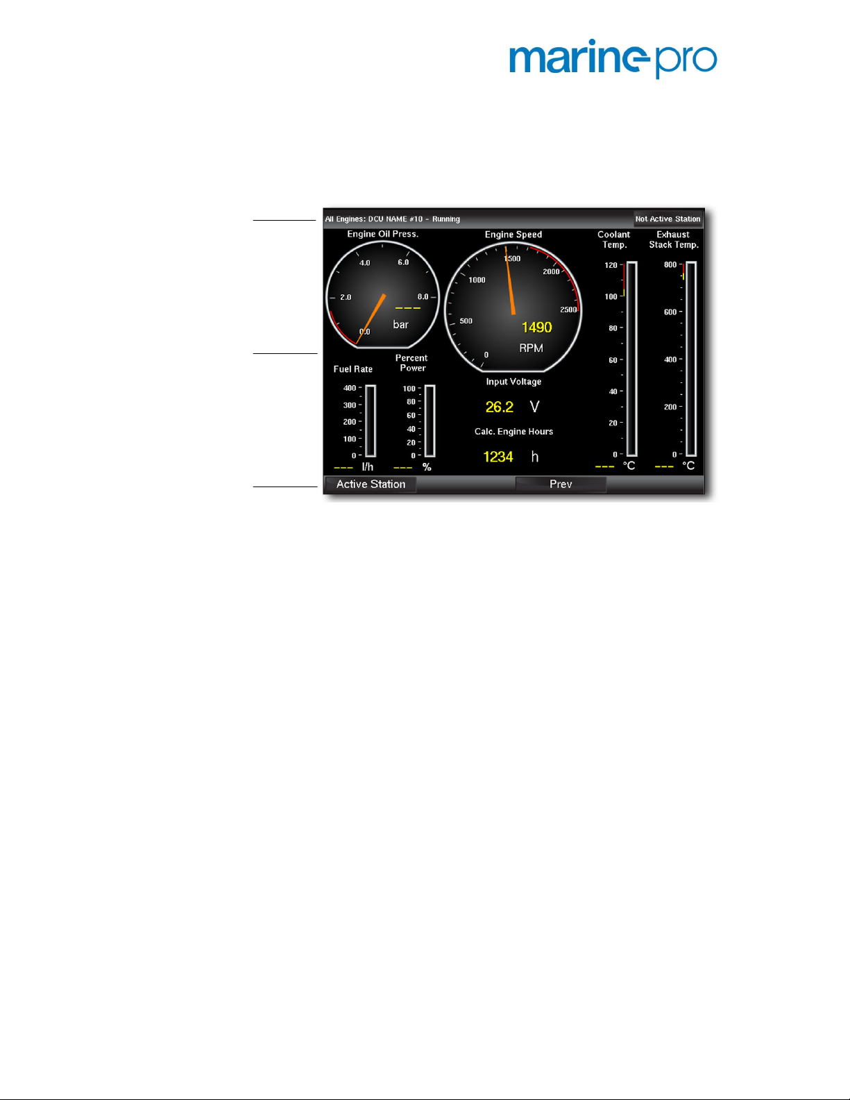
The screen is divided into three main sections:
•
Status bar Top most line on the screen, which is
reserved for status symbols.
P a g e | 22 Marine Pro User's Manual
Page 25
Status bar
Main screen area
• Soft button line Bottom most line on the screen,
which is reserved for soft buttons, which have
different meaning depending on the selected
screen.
• Main screen area This is where all instruments
and menu icons are displayed.
Button area
Button# 1 2 3 4
Page 26
E
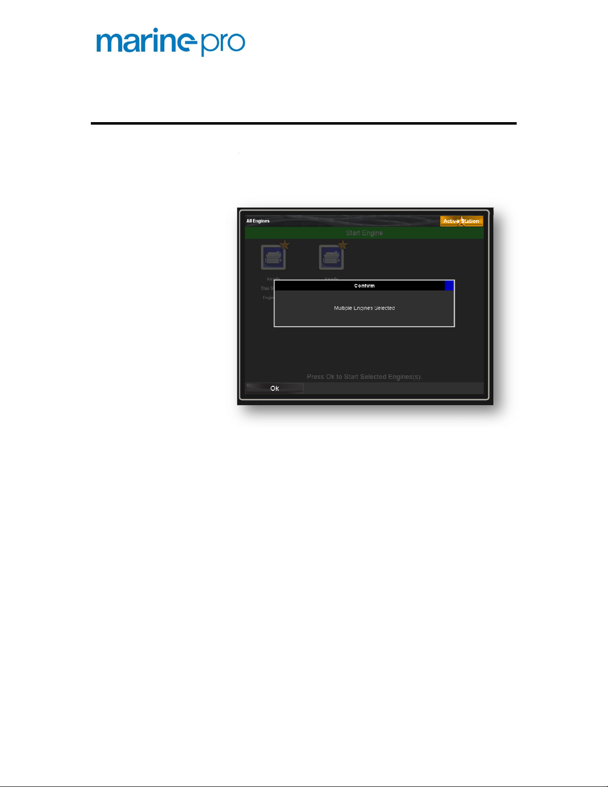
Start of multiple engin
simply by selecting the engine(s) to start.
If selecting more than one engine, the RP warns you with
a simple dialog.
To start the engine
es at the same time is
Select the engine(s) to start by pressing the touch
have
button again to start the
Start and Stop
Start Engine(s)
ngines
possible,
1. Press the Start Button.
2.
screen. The selected engine icons will
rectangle.
3. Press the OK
engine(s).
a white
selected
Page 27
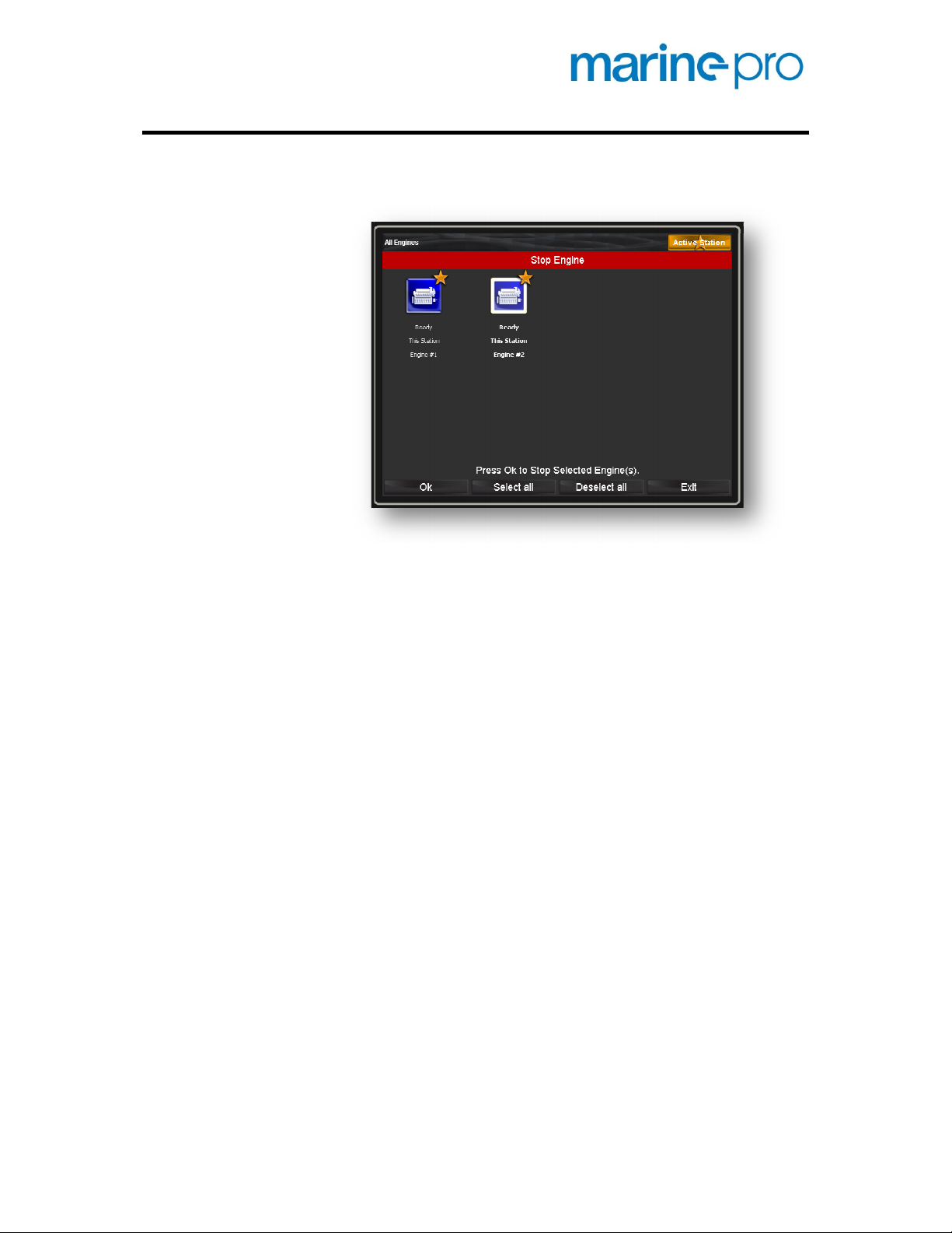
Stop Engine(s)
Stop of multiple engines at the same time is possible
simply by selecting the engine(s) to stop.
To s
t the engine(s) to stop by pressing the touch
The selected engine icons will have a white
button again to stop the
top the engine
1. Press the Stop Button
4. Selec
screen.
rectangle.
2. Press the OK
engine(s).
,
selected
Page 28

Alarm List
Press the Alarm List button to enter the alarm list. All
current alarms are visible on the screen.
Press the Alarm List button again to leave the alarm list.
For more information about the alarm list, please see
page
If the buzzer sounds, press the alarm list button to
silence the buzzer.
Acknowledge a single alarm
in the alarm list, this operation will
If already in the alarm list when the buzzer sounds,
button to silence the
r will not leave the alarm list, but silence the
First, select the alarm to acknowledge by touching
will expand to reveal additional
ess the Acknowledge button to acknowledge the
Enter the Alarm List
Silence the Buzzer
Acknowledge Alarms
38.
• If not already
display the alarm list.
•
then pressing the alarm list
buzze
buzzer.
•
it. The alarm line
information, if any.
• Pr
selected alarm.
Page 29
Acknowledge all alarms
• While in the alarm list, press and hold (1 second)
the Acknowledge button. This acknowledges all
alarms.
Note!
Alarms that are still active will still be displayed in
the screen until they go inactive. They are shown with a
grey background.
The Star in the Alarm List
If a star is displayed prior to the engine name, it means
this RP is the active station for that engine.
These alarms can be acknowledged on this RP.
Alarms without a star prior to the engine name cannot be
acknowledged until this RP has become the active station
for that engine.
Filter Alarms
The RP can receive alarms from up to eight different DCU
panels at a time, so it is important to be able to filter
alarms.
There are two buttons for this purpose:
• Engine Views (soft button 2)
• Alarm Views (soft button 3)
Note!
If a filter is applied, this is visualized with a yellow
dot in the button.
Engine Views
Press Engine Views for an engine filter selection. This lists
all engines the RP is connected to, and also This Station
and All.
This Station
This selection will not display alarms from any of the DCU
panels, but only alarms built into the RP panel.
The alarm can be eg. “Lost contact to 192.168.0.102” or
“Low battery voltage”.
Engine Name
Press any of the engine names to display alarms from this
engine only. All other engines and also RP panel alarms
are suppressed.
All
This effectively turns off all filters and displays all alarms
from all sources.
Marine Pro User's Manual P a g e | 27
Page 30
Home Button
Alarm Views
Press Alarm Views to filter alarm types from the DCU
panels.
Panel Alarms
This selection filters away diagnostic alarms from the
ECM1, and displays all other alarms.
ECM Diagnostics
This selection filters away all alarms but the diagnostic
messages and alarms coming from the engine ECM.
All
This effectively turns off all filters and displays all alarms
from all sources.
Press the Home button (house symbol) to display the top
level engine instruments.
This is a handy button to quickly revert to a known place.
Main Menu shortcut
Press and hold (1 second) the Home button to display the
Menu.
1
ECM = Engines Electronic Control Module
P a g e | 28 Marine Pro User's Manual
Page 31
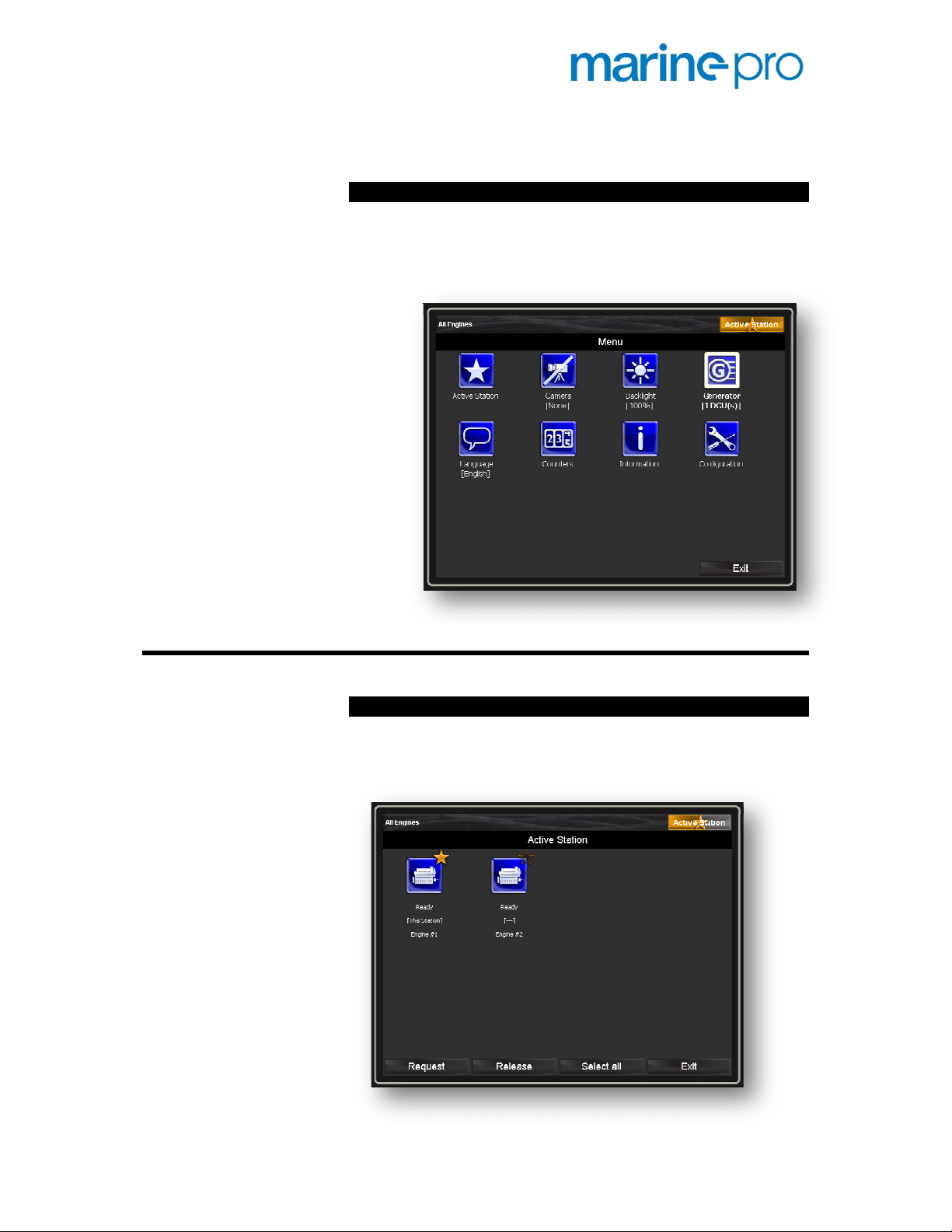
The Menu
Access the Menu
The menu can be accessed from two places:
Active Station
This is used when there are multiple RP stations in the
installation.
Press this menu icon to bring up the Active Station dialog.
Press the Home button. Now, the menu is available
1 second
•
from softbutton #1.
• Press and hold the Home button (
).
Menu selections
Page 32

Camera
An IP-camera can be connected to the Ethernet network,
and the image will be displayed on the RP screen.
Up to
All four images can be displayed simultaneously, or one
image can take the entire screen.
Note!
second.
four
cameras can be connected to one RP screen.
The image update rate is 4-5 fps – frames per
Expand to full screen
Touch anywhere on one of the four camera images to
expand to full screen view for that camera.
Reduce to 1/4th of the screen
Touch anywhere on the full size image to reduce it to
1/4th of the screen size.
Backlight
Select between different screen backlight settings.
• 10% backlight is as dark as it can be
• 50% backlight is half full
• 100% backlight is fully lit
• Automatic varies between 10% and 100%, using an
inbuilt ambient light detector.
• Night Mode is the same as Automatic, with the
difference that it will turn the screen completely off
10 seconds after no action has taken place. The
screen will awake on any alarm or user input, and
stay lit as long as there are unacknowledged
alarms.
P a g e | 30 Marine Pro User's Manual
Page 33

Generator
If the DCU engine panel is reading generator parameters
from the RIO 425, then the generator image and values
will be displayed here.
Language
Select the
Note!
unit
installation of the DCU.
If a language is selected where there is no translation, the
default language will be used.
The instruments text descriptions reside in the DCU
and must be translated for each language during
s
desired RP operator language.
,
Page 34
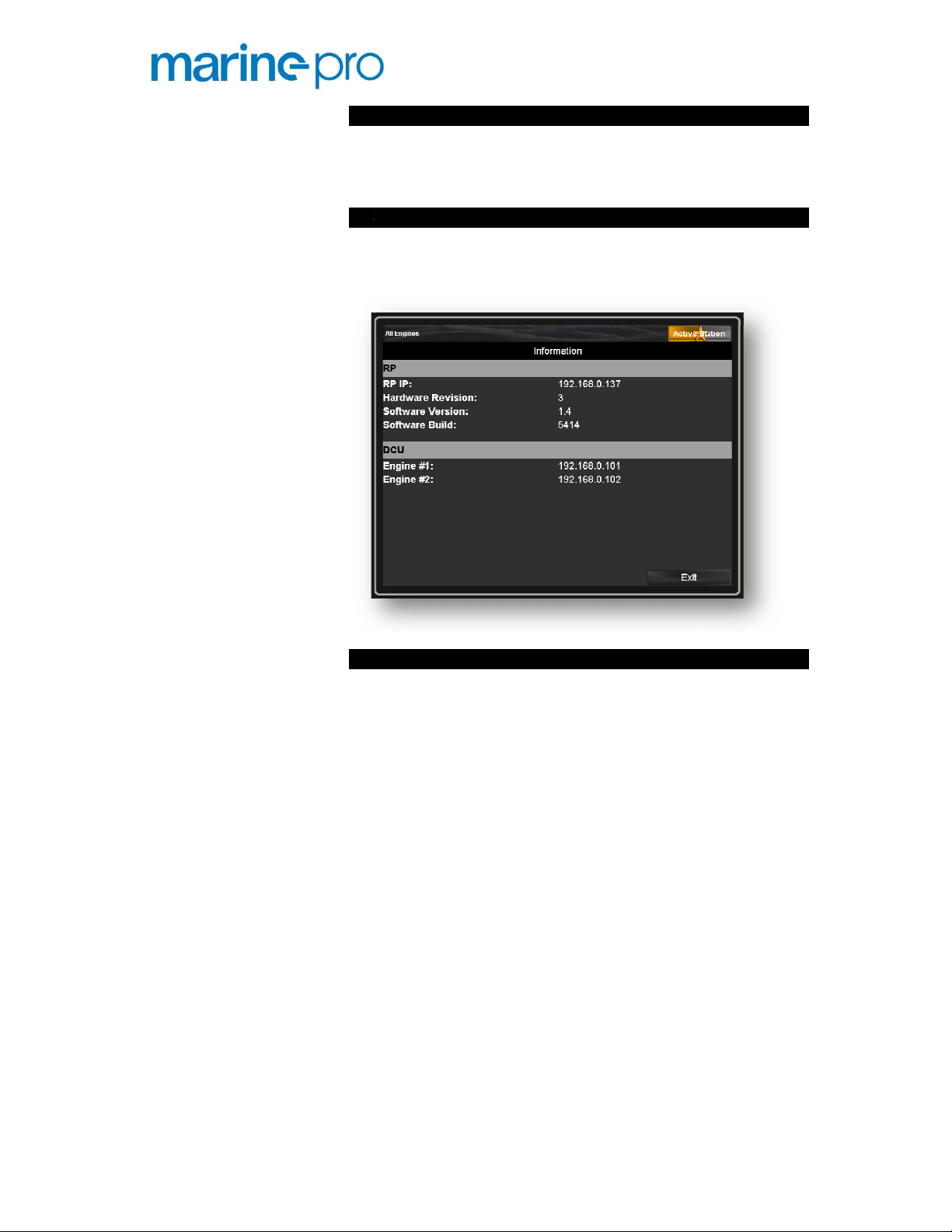
Counters
The counters page disp
the engines.
Information
This page displays IP addresses and revision numbers.
The DCU section displays the IP address of the connected
engine panels.
Configuration
This leads to the
and is
lays engine running hours for all
onfiguration submenu section
user c
not password protected.
,
Page 35

ions
Wallpaper
The wallpaper is the background image in the instrument
screens.
Predefined wallpapers
Select appropriate background wallpaper from the
selection of available wallpapers.
Up to eight wall
Personal wallpaper
New
interface.
Please consult the
more information.
Button Beep
Select whether a button press and a tap on the touch
screen should
sound)
The function toggles on/off.
Sound Configuration
The RP has inbuilt a pair of speakers and a buzzer. Using
this selection, choose between the buzzer beep, or the
inbuilt sounds through the speakers.
Note
andar
con
speakers).
papers may come with the unit.
personal wallpaper can be uploaded using the web
Installation Manual for
(or the speaker
he speaker sound is also available on the 3.5mm
panel
typically
Configuration select
Marine Pro
make the buzzer beep
or not.
!
T
st
d minijack output on the
nection to external speakers (
rear, for
PC brand
Page 36
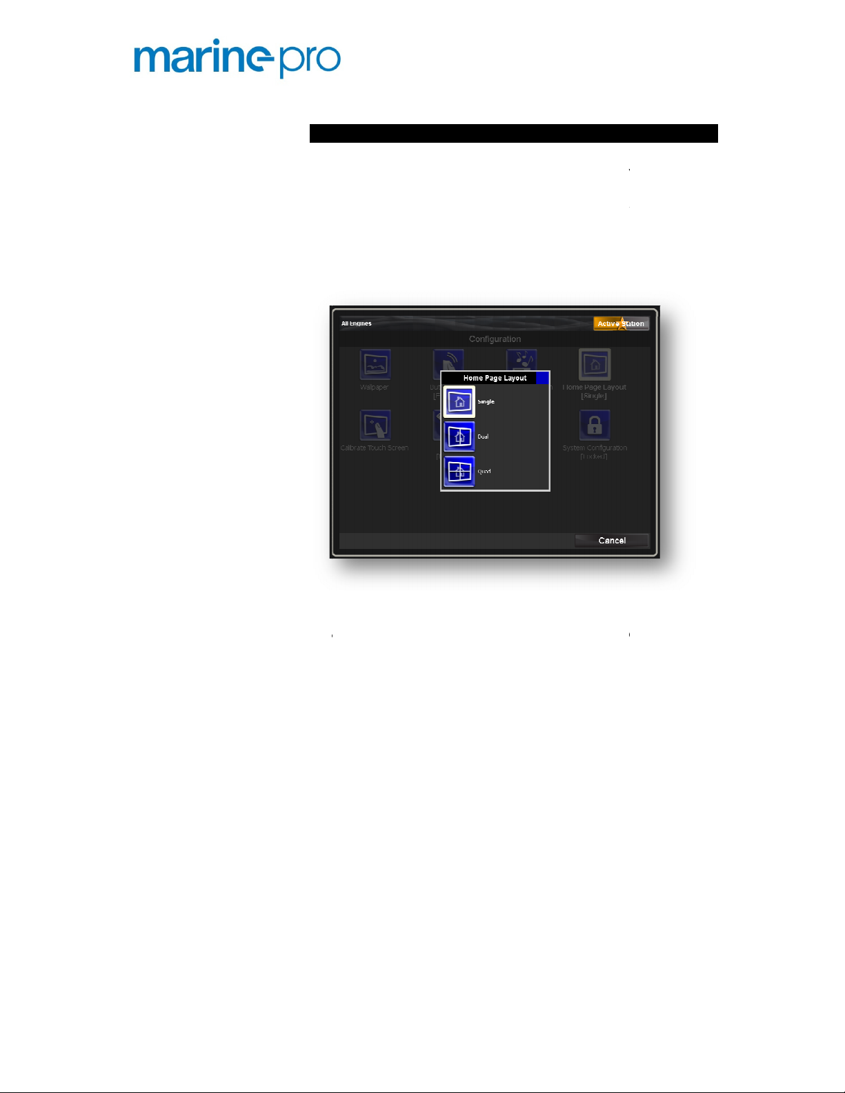
Home Page Layout
The Home page is accessed by pressing the Home button,
and is the top level in the instrument hierarchy.
The Home page can use its entire area for
instruments, or it
quadrants, where each quadrant houses instruments for
other
For instance, if there are three engines connected to the
RP, one can choose the following layout:
Single
If Single Screen is selected, pressing the
display the engine with the lowest IP number (usually
engine #1).
Access to other engines
buttons.
Dual
If the screen is divided in two
displays engine #1, and the right pane displays e
#2.
Access to other engines
buttons.
Quad
If the screen is divided into four quadrants, the top left
quadrant displays engine #1, the top right quadrant
displays engine #2, and the bottom left quadrant displays
engine #3.
ote!
these engines will be from the Previous/Next buttons.
can be divided into two or four
Home button
from the Previous/Next
, the left pane
from the Previous/Next
8 engines installed, the access to
one engine
engines.
N
If there are 4-
will
will be
halves
ngine
is
Page 37

Calibrate Touch Screen
If the touch screen is hard to navigate, it
recalibration.
Emergency
In case the screen is out of
cannot be used, press the Home
to access
Units
Select units
Troubleshooting
This page displays
System Configuration
This leads to the System Configuration submenu section.
This section is password protected.
The password is a four
If the wrong number is entered, the panel will issue an
encrypted code. This code can be us
revert to the original password.
calibration to the extent it
button for ten seconds,
information.
ed by the factory to
access
the calibration screen.
• Metric (Celsius, bar, etc), or
• U.S. (Fahrenheit, psi, etc)
troubleshooting
may need a
-digit number.
Page 38

Symbols and Indication Icons
Local mode – L
When the symbol L is displayed, the corresponding DCU
engine panel is in Local mode.
The RP cannot acknowledge alarms, nor command start
or stop on this DCU panel.
Toggle the Local/Remote button on the DCU to take it out
of Local mode.
Manual mode – M
When the symbol M is displayed, the corresponding DCU
engine panel is in Manual mode.
The DCU will not do automatic start, nor will it do
automatic stop, in Manual mode.
Shutdown Override – SO
When the symbol SO is displayed, the corresponding DCU
engine panel is in Shutdown Override mode.
The DCU will not do automatic shutdowns in this mode.
Note!
Overspeed shutdown is the exception to this rule.
Service and Diagnostics – wrench symbol
Whenever a predefined service is due, or a white
diagnostic from the ECM is active, the service wrench
symbol is displayed in the status bar.
Active Station symbol
The Active Station symbol is the large rectangular symbol
displayed in the top right corner. It can have three
meanings:
Inactive Station
The RP is not active station for any engines.
The symbol is all black, with the text “Inactive Station”.
Partially Active Station
The RP is active station for one or several engines, but not
all.
The symbol is half orange, half black, with the text
“Active Station”.
P a g e | 36 Marine Pro User's Manual
Page 39

Active Station
The RP is active station for all engines in the network.
The symbol is full orange, with the text “Active Station”.
Active Station – star symbol
In single engine view, and if the RP is the active station
for the engine, an orange star is displayed in the status
bar to indicate this.
If the Home screen is divided into two or four quadrants,
the active station star is displayed in the name and engine
status banner.
Warning and Alarm Triangles
Yellow triangle
A yellow triangle means there is a warning on this
channel. If it flashes, it is unacknowledged.
Red triangle
A red triangle means there is an alarm or shutdown
situation on this channel. If it flashes, it is
unacknowledged.
In both cases, press the Alarm List button for details of
the warnings/alarms.
Marine Pro User's Manual P a g e | 37
Page 40

DCU and RP Common
Alarm List colors explained
In general
• Alarm and Shutdown (Automatic Stop) entries are
displayed in
• New alarms (unacknowledged) are displayed in
bold
text, and acknowledged alarms are displayed
in normal text.
• An alarm that is not acknowledged, then goes
inactive, is displayed in normal text on a grey
background.
o
Red text color means it was an Alarm or
Shutdown.
o
Yellow text color means it was a Warning.
New active Alarm (red background)
Acknowledged active Alarm (
Unacknowledged inactive Alarm (
background
New active Warning (yellow background)
Acknowledged active Warning (
Unacknowledged inactive Warning (
Unacknowledged White Diagnostic (white background)
Acknowledged White Diagnostic (
Unacknowledged inactive Diagnostic (
)
Alarm List example entries
red
. A Warning is displayed in
red background
red text, grey
yellow background
yellow text, grey background
white background
black text, grey background
yellow
)
.
)
)
)
)
P a g e | 38 Marine Pro User's Manual
 Loading...