


Manual# 1100269
Installation and
Configuration Manual
DCU 410/408 – Engine Control Unit
RP 410 – Remote Panel
FW 2.11


400 Series Installation and Configuration
400 Series Overview 1
Table of Content
Document Information .................................. 2
Ordering Information .................................... 3
About this manual ......................................... 3
Responsibilities .............................................. 3
400 SERIES OVERVIEW ........................................ 5
TYPICAL LAYOUT ..................................................... 5
Available units in the 400 Series .................... 5
PRECAUTIONS IN CLASSED SYSTEMS ........................... 7
DCU 410 ENGINE PANEL INSTALLATION .............. 8
MECHANICAL INSTALLATION ..................................... 8
Location ......................................................... 8
WIRE TERMINAL LAYOUT OVERVIEW .......................... 9
ELECTRICAL CONNECTIONS ..................................... 13
General ........................................................ 13
Grounding .................................................... 13
Primary Power Supply [1 – 2] ...................... 13
Secondary Power Supply [3 – 4] .................. 14
Power Supplies in General [1 – 4] ................ 14
Auxiliary Power Output [5 – 6] .................... 15
System On/Off [7 – 10] ................................ 16
Reserved [11 – 15] ....................................... 16
Switch Input Channels [16 – 26] .................. 16
4-20 mA Input Channels [27 – 31] ............... 17
PT100 Input Channels [32 – 43] ................... 17
Magnetic Pickup (Speed) Sensor [44 – 45] .. 18
CANopen/J1939#2 Interface (COM 5) [46 –
48] ............................................................... 18
CAN J1939 Interface (COM 4) [49 – 51] ....... 18
MODBUS RTU, RS-485 (COM 3) [52 – 56] .... 18
RIO 410 Link (COM 2) [57 – 59] ................... 19
SDU 410 Link (COM 1) [60 – 62] .................. 19
Configurable Relays [63 – 68] ...................... 19
Configurable 24VDC Outputs [69 – 72, 76-78]
..................................................................... 20
Common Alarm Relay [73 – 75] ................... 20
Shutdown Output [79] ................................. 20
ETS – Energize to Stop [80] .......................... 20
ETR – Energize to Run [81] .......................... 20
Running [82] ................................................ 20
Crank [83] .................................................... 21
Prelube Act. [84] .......................................... 21
24V Supply for Fixed Function Inputs [85] ... 21
Prelube Comp. [86] ...................................... 21
Start Disable [87] ......................................... 21
Automatic Mode [88] .................................. 21
Automatic Start [89] .................................... 21
Automatic Stop [90] .................................... 22
Remote Start /Stop [91 – 92] ....................... 22
Acknowledge [93] ........................................ 22
Shutdown Ovrd. [94] ................................... 22
In Gear [95] .................................................. 23
Configurable Inputs [96 – 97] ...................... 23
Shield (Grounding) [100] ............................. 23
Other Communication Interfaces ................ 23
Rear Lid Graphical Layout............................ 26
FIRST POWER-ON ................................................. 26
Preparations ................................................ 26
First Power-On Wizard ................................ 27
CONFIGURATION OF THE DCU ................................ 30
Configuration- and Firmware files ............... 30
Connecting to the DCU ................................ 31
Further connection settings ......................... 32
WEB SERVER CONFIGURATION ................................ 35
Home ........................................................... 35
Home – DCU ................................................ 38
Home – DCU – I/O Configuration ................ 40
Home – DCU – Interface Design .................. 63
Home – DCU – Start/Stop/Prelube .............. 65
Home – DCU – User Interface ...................... 72
Home – DCU – Engine Model ...................... 73
Home – DCU – Service Interval .................... 73
Home – DCU – Communication ................... 74
Home – DCU – Miscellaneous ...................... 78
Home – DCU – Language ............................. 84
COMMUNICATION INTERFACE LIST ........................... 85
DCU 410 AND DCU 408 CAPACITY ......................... 85
Functionality and content highlights ........... 85
Total I/O capacity ........................................ 86
RP 410 REMOTE PANEL INSTALLATION .............. 87
Location ....................................................... 87
GENERAL OVERVIEW ............................................. 88
ELECTRICAL CONNECTIONS ..................................... 89
Wire Terminal Layout Overview .................. 89
Rear Lid Graphical Layout............................ 90
SYSTEM CONFIGURATION ICON SELECTIONS ............... 90
ADD-ON MODULES ............................................ 96
SDU 410 SAFETY UNIT ......................................... 96
Wire Terminal Layout Overview .................. 97
Configuration of the SDU 410 ...................... 99
RIO 410 EXPANSION I/O .................................... 101
Wire Terminal Layout Overview ................ 101
RIO 410 Addressing ................................... 104
RIO 410 Configuration ............................... 104
RIO 425 GENERATOR INTERFACE UNIT .................. 106
MK-14 RELAY EXPANSION ................................... 108
2 400 Series Overview
400 Series Installation and Configuration
Document Information
Valid Versions
This Installation Manual is valid for the following firmware
releases of the DCU 410/408, and the RP 410.
Panel
Firmware
Release
DCU 410
2.11
June 2014
DCU 408
2.11
June 2014
RP 410
2.11
June 2014
Manual Revisions
Title:
400 Series Installation and Configuration
Revision:
June 10, 2015
Copyrights and Trademarks
Copyright © Auto-Maskin AS, 2015
Information given in this document may change without
prior notice. This document shall not be copied without
written permission from Auto-Maskin.
All trademarks acknowledged.
Contact Information
Auto-Maskin AS
Hvamsvingen 22
NO-2013 SKJETTEN
Norway
www.auto-maskin.com

2 400 Series Overview
400 Series Installation and Configuration

400 Series Installation and Configuration
400 Series Overview 3
Ordering Information
The following parts are available in Marine Pro.
Item
Part #
DCU 410 Engine Control Unit
1006450
DCU 408 Engine Control Unit
1006455
RIO 410 I/O Expansion Unit
1006453
RIO 425 Generator Interface Unit
1006409
RIO 412 Exhaust Monitoring Unit
1006454
SDU 410 Safety Unit
1006451
RP 410 Remote Panel Unit
1006452
MK-14 Relay Expansion
1121341
Ethernet Switch, 5 channels, 24V supply, DIN-rail
1050165
J1939 CAN bus Cable
1009110
IP Camera
1121258
About this manual
This manual has been published primarily for
professionals and qualified personnel. The user of this
material is assumed to have basic knowledge in marine
systems, and must be able to carry out related electrical
work.
Work on the low voltage circuit should only be carried out
by qualified and experienced personnel. Installation or
work on the shore power equipment
must only
be carried
out by electricians authorized to work with such
installations.
Responsibilities
It is the
sole responsibility of the installer
to ensure that
the installation work is carried out in a satisfactorily
manner, that it is operationally in good order, that the
approved material and accessories are used and that the
installation meet all applicable rules and regulations.

4 400 Series Overview
400 Series Installation and Configuration
Note! Auto-Maskin continuously upgrades its products
and reserves the right to make changes and
improvements without prior notice.
All information in this manual is based upon information
at the time of printing.
For updated information, please contact your local
distributor.

400 Series Installation and Configuration
400 Series Overview 5
400 Series Overview
Typical Layout
The following shows a typical layout. The SDU safety unit
is used in classed installations, whereas the RIO
expansion units are used to expand the I/O capacity.
The RP remote panels can be attached for remote
monitoring and control.
Available units in the 400 Series
DCU 410 and DCU 408 Engine Control Units
DCU 410 and DCU 408 are the engine monitoring and
control units. One panel is required for each engine.
The DCU 410 has a colour screen and buttons for user
interaction.

6 400 Series Overview
400 Series Installation and Configuration
The DCU 408 is the low cost version of the DCU 410,
without a user interface, and intended for use with
remote panels.
The DCU 410 and DCU 408 are hereafter referred to as
the “DCU”.
SDU 410 Safety Unit
The SDU 410 (hereafter referred to as the “SDU”) is the
safety unit, which is mandatory in a classed installation. It
is completely self-contained and separate from the DCU.
The DCU communicates with the SDU on a link.
RIO 410 I/O Expansion Unit
The RIO 410 (hereafter referred to as the “RIO”) is an
expansion I/O unit. A maximum of four RIO units can be
connected to any one DCU.
The DCU communicates with the RIO on a link, and when
connected, the DCU automatically detects the unit and
add it into its configuration.
RIO 425 Generator Interface Unit
The RIO 425 is a generator interface unit. It is linked to
the DCU, which will find it automatically.
When connected, a new page is made available on the
DCU – and on the remote panel RP 410 – that displays
generator parameters such as phase voltages, phase
currents, frequency, power, efficiency factor (Cos phi),
etc.
RIO 412 Exhaust Monitoring Unit
The RIO 412 is a compact unit with 20 thermocouple
channels. Each cylinder’s thermocouple is connected to a
predefined channel on the unit.
The DCU automatically detects the unit, and adds a new
page with exhaust temperature data, such as individual
cylinder temperature, average temperature, etc.
RP 410 Remote Panel Unit
The RP 410 (hereafter referred to as the “RP”) is the
remote panel for the DCU.

400 Series Installation and Configuration
400 Series Overview 7
One RP can monitor and control a maximum of eight DCU
engine units, and there can be an unlimited number of RP
units in the network. Each RP can monitor the same
engine, or it can monitor separate engines.
The RP communicates to the DCU on Ethernet.
Note! For redundant Ethernet connection use
managed
Ethernet switches.
Precautions in Classed Systems
Requirements
In a classed and type approved installation, the following
is required:
The DCU 410 and DCU 408 engine control units
requires:
o Separate power supplies to its primary and
secondary supply inputs.
o An engine speed sensor connected to the
DCU. This can be physical, or from the
J1939 CAN bus.
The SDU 410 Safety Unit requires:
o Minimum one engine speed sensor
connected to the SDU.
o Must be supplied by an alternative supply to
the DCU 410 primary supply.
Certification
All modules in the 400 Series are certified by major
classification societies.
Certificates can be obtained from the Auto-Maskin
website, or from your local distributor.

8 DCU 410 Engine Panel Installation
400 Series Installation and Configuration
DCU 410 Engine Panel
Installation
Mechanical Installation
Location
The DCU is normally located in the engine room due to
the number of cables and wires from the engine sensors
and to reduce electrical noise levels, which might else
result from long cable stretches.
The DCU should be mounted at about eye level and the
user should have easy access to all buttons on the panel.
The DCU may be mounted on the engines supporting
structure provided shock absorbers are used either
between the structure and the engine, or between the
structure and the DCU. The DCU shall not be mounted
directly onto the engine due to vibrations.
The DCU should be mounted so that easy access to the
cable connections at the back is ensured. This might for
instance be accomplished by mounting it in a cabinet with
a hinged front panel.

400 Series Installation and Configuration
DCU 410 Engine Panel Installation 9
Wire Terminal Layout Overview
These are the wire terminals on the DCU back lid.
Power supply inputs /auxiliary power output
1
+24VDC Primary Supply
In 2 0V Primary Supply
In
3
+24VDC Secondary Supply (Redundant)
In 4 0V Secondary Supply
In 5 24VDC Supply Out, 1A
Out
6
0V Supply Out
Out
System On / Off
7
+24VDC 0.2A Supply for Power On
Out
8
Power On 24VDC
In 9 0V Opto Supply for Power On
Out
10
0V Supply for Power On
In
Reserved for future expansion
11
No connection
-
12
No connection
-
13
No connection
-
14
No connection
-
15
No connection
-
Switch Inputs Channels (8 channels)
16
+24VDC 0.2A Supply for Switch Inputs
Out
17
#1 Switch Input 24V
In
18
#2 Switch Input 24V
In
19
#3 Switch Input 24V
In
20
#4 Switch Input 24V
In
21
#5 Switch Input 24V
In
22
#6 Switch Input 24V
In
23
#7 Switch Input 24V
In
24
#8 Switch Input 24V
In
25
0V Opto For Switch Input
Out
26
0V For Switch Input
In

10 DCU 410 Engine Panel Installation
400 Series Installation and Configuration
4-20 mA Inputs (4 channels)
27
+24VDC 0.2A Supply for 4-20 mA Sensors
Out
28
#1 4-20 mA Input
In
29
#2 4-20 mA Input
In
30
#3 4-20 mA Input
In
31
#4 4-20 mA Input
In
PT100 inputs (4 channels)
32
#1 PT100 A
In
33
#1 PT100 B
In
34
#1 PT100 C
In
35
#2 PT100 A
In
36
#2 PT100 B
In
37
#2 PT100 C
In
38
#3 PT100 A
In
39
#3 PT100 B
In
40
#3 PT100 C
In
41
#4 PT100 A
In
42
#4 PT100 B
In
43
#4 PT100 C
In
Pickup input (tacho / speed input)
44
#1 Pickup A
In
45
#1 Pickup B
In
CANopen /J1939#2 interface (COM 5)
46
#1 CANopen/J1939#2 Shield
-
47
#1 CANopen/J1939#2 L
-
48
#1 CANopen/J1939#2 H
-
CANJ1939 interface (COM 4)
49
#1 CAN J1939 Shield
-
50
#1 CAN J1939 L
-
51
#1 CAN J1939 H
-
MODBUS RTU (COM 3)
52
Modbus 0V
In
53
Modbus Shield
-
54
Modbus L
-
55
Modbus H
-

400 Series Installation and Configuration
DCU 410 Engine Panel Installation 11
56
Modbus +24VDC Supply
In
RIO 410 Remote I/O Interface (COM 2)
57
RIO 410 Remote I/O Interface Shield
-
58
RIO 410 Remote I/O Interface L
-
59
RIO 410 Remote I/O Interface H
-
SDU 410 Safety Module Interface (COM 1)
60
SDU 410 Safety Module Interface Shield
-
61
SDU 410 Safety Module Interface L
-
62
SDU 410 Safety Module Interface H
-
Configurable Relays
63
#1 Configurable Relay NC
Out
64
#1 Configurable Relay C
Out
65
#1 Configurable Relay NO
Out
66
#2 Configurable Relay NC
Out
67
#2 Configurable Relay C
Out
68
#2 Configurable Relay NO
Out
Configurable 24VDC Outputs
69
#1 Configurable Output 24VDC
Out
70
#2 Configurable Output 24VDC
Out
71
#3 Configurable Output 24VDC
Out
72
#4 Configurable Output 24VDC
Out
Common Alarm Relay
73
Common Alarm Relay NC
Out
74
Common Alarm Relay C
Out
75
Common Alarm Relay NO
Out
Configurable 24VDC Outputs
76
#5 Configurable Output 24VDC
Out
77
#6 Configurable Output 24VDC
Out
78
#7 Configurable Output 24VDC
Out
Fixed 24VDC Outputs
79
Energize to Shutdown 24VDC
Out
80
Energize to Stop (ETS) 24VDC
Out
81
Energize to Run (ETR) 24VDC
Out
82
Engine Running 24VDC
Out
83
Crank (Start) 24VDC
Out

12 DCU 410 Engine Panel Installation
400 Series Installation and Configuration
84
Prelube Activation 24VDC
Out
Fixed 24VDC Inputs
85
+24VDC Supply for Fixed Functional Inputs
Out
86
Prelube Complete 24VDC switch input
In
87
Start Disabled 24VDC switch input
In
88
Automatic Mode 24VDC switch input
In
89
Automatic Start (PMS) 24VDC switch input
In
90
Automatic Stop (PMS) 24VDC switch input
In
91
Remote Start 24VDC switch input
In
92
Remote Stop 24VDC switch input
In
93
Remote Acknowledge/Silence Alarm 24VDC
switch input
In
94
Shutdown Override 24VDC switch input
(engine protection override)
In
95
In Gear 24VDC switch input
In
96
#1 Configurable Input 24VDC switch input
In
97
#2 Configurable Input 24VDC switch input
In
98
0V Opto For Fixed Functional Inputs
In
99
0V For Fixed Functional Inputs
In
Ground (PE)
100
Ground
-
Ethernet MODBUS/TCP (COM 6)
COM 6
RJ45 Ethernet port
In/Out
Console (COM 7)
COM 7
DSUB-9 (RS-232) serial port
In/Out
MK-14 Relay Expansion Module Link (COM 8)
COM 8
DSUB-15
In/Out
USB Interface
USB
USB Memory Interface
In/Out

400 Series Installation and Configuration
DCU 410 Engine Panel Installation 13
Electrical Connections
General
To protect against EMC noise, we recommend that all
cables are shielded.
Note! The screen of all cables shall be connected to
ground/hull, NOT to 0V!
Some cables shall be kept as separate from other signals
as possible – for instance the pickup signal. Others can be
in a shielded multi-cable.
Note! Connect shield at one end only.
Grounding
Note! Please keep ground and 0V separated!
In marine installations, ground and 0V volt should not be
connected together. In a ship installation, the hull is the
“ground” whilst the battery minus is the 0V.
In the DCU system, +24V and 0V are filtered to ground
using special filter components. This is done to reduce
electrical noise entering the system. If ground and 0V are
connected together, these filters do not work properly.
Note! Make a ground connection to terminal 100. Keep
this wire as short as possible, and at least 1.5mm2.
Terminals 46, 49, 53, 57, 60 and 100 are all ground
connections, internally connected to ground, and should
not
be connected to 0V.
Primary Power Supply [1 – 2]
The DCU is designed to run on 24VDC supply voltage.
Note! Make sure the primary supply power is sourced
directly from the battery, NOT from the starter of the
engine, as the voltage drop over the latter is significantly
higher.
Power Supply Requirements
Valid full functionality range: 18-32VDC.

14 DCU 410 Engine Panel Installation
400 Series Installation and Configuration
Minimum capacity: 5A
Note! There are fixed low battery voltage alarm setpoints.
For the primary supply, these are at 21V and 18V. For the
Secondary supply, the setpoint is at 20V.
All these alarms are delayed.
Use a twisted pair wire to minimize the effect of noise on
the supply cables. Connect the cables straight from the
battery (and NOT the starter engine) and keep the cable
as short as possible.
Use at least 2.5mm2 wires for the power supply.
Secondary Power Supply [3 – 4]
It is recommended that the secondary supply is connected
to a redundant power supply to ensure sufficient supply
voltage upon cranking the engine.
Without a separate secondary supply, a crank can result in
a reboot of the DCU.
Power Supplies in General [1 – 4]
Mandatory straps when not using opto-coupling
The DCU support opto-coupled inputs and outputs on
several of its terminals.
When this capability is not used, the following straps
must be inserted.
Purpose
Strap
Comment
Power the DCU
7-8 and 9-10
Disconnect jumper 7-8 to
set the DCU into System
Off mode.
Activate Switch
Inputs
25-26
Disconnect this jumper if
an external 24V supply
(not terminal 16) is used
to activate the switch
inputs.

400 Series Installation and Configuration
DCU 410 Engine Panel Installation 15
Activate Fixed
Functions
98-99
Disconnect this jumper if
an external 24V supply
(not terminal 85) is used
to activate the functions.
Supply Selection
The DCU internal circuitry is sourced from either the
primary OR the secondary supply.
The primary supply has priority over the secondary
supply. If the primary supply voltage drops below 18V,
the DCU will immediately switch over and use the
secondary supply, but only if the secondary supply is
above 20V.
The primary supply is selected over the secondary supply
when the primary supply voltage again rises above 18V.
There is a two second delay when switching from
secondary to primary supply.
The DCU will run equally well – with full functionality – on
the secondary supply.
All voltage levels are +/- 5%.
Power Supply Low Alarms
The active supply (the supply currently feeding the DCU)
is monitored. This is normally the primary supply.
If the supply falls below 21V+30sec, this is
indicated with an amber alarm.
If the supply falls below 18V+30sec, this is
indicated with a red alarm.
Auxiliary Power Output [5 – 6]
The Auxiliary Power Output is intended to drive auxiliary
instruments, relays, Ethernet switches, etc. that should be
powered together with the DCU.
The Auxiliary supply is secured with an automatic fuse.

16 DCU 410 Engine Panel Installation
400 Series Installation and Configuration
System On/Off [7 – 10]
The DCU has a System On/Off function. System On is the
normal mode of operation.
In System Off mode, the DCU internal circuitry is still
active, but it acts as powered off.
Normal operation
To power the DCU for normal operation, connect a strap
between terminals 7-8 and another strap between
terminals 9-10.
The DCU is now always on.
System Off
To set the DCU in System Off mode, remove the strap
between terminals 7-8.
The 24VDC supply at terminal 7 is secured with a 10mA
automatic fuse.
System On
To activate the DCU, connect terminals 7-8 again. The
DCU is immediately ready for use.
External supply
Alternatively, this function can be activated with an
external 24V supply. In this case, do not connect any
jumpers, and do not use terminals 7 and 10.
To activate the DCU (System On), connect a 24V supply to
terminal 8, and the 0V to terminal 9.
Reserved [11 – 15]
Not implemented in this release.
No connection to these terminals.
Switch Input Channels [16 – 26]
There are eight configurable switch input channels which
can be used to detect the status of switches in the
installation.

400 Series Installation and Configuration
DCU 410 Engine Panel Installation 17
The state of each channel is controlled by the voltage
between the +24V switch input terminal (terminals 17-
24) and the +0V opto terminal (terminal 25) as follows:
0 – 2V = logic “0”
8 – 32V = logic “1”
2 – 8V = undefined, avoid this area.
Further switch input details
Overvoltage protection: 40 VDC
Not connected = 0V (47 kohm pull-down).
The 24VDC on terminal 16 shall be used for the switch
input supply. It is secured with a 40 mA automatic fuse.
Normal Use
Terminals 25 and 26
shall
be strapped.
Terminals 17 - 24 connected to 24V (terminal 16)
through external switches.
Opto-coupled Use
Terminals 25 and 26 shall
not
be strapped.
External voltage input between terminals 17 - 24 (+24V)
and terminal 25 (0V opto) is electrically isolated from the
DCU by the means of integrated opto-coupled devices.
4-20 mA Input Channels [27 – 31]
There are four configurable 4-20 mA analogue sensor
inputs.
If the signal is out of range, a warning will be displayed.
Out of range is defined as:
<2 mA (broken)
>24 mA (short)
Update rate: 2Hz
PT100 Input Channels [32 – 43]
There are four PT100 input channels. The channels
support PT100 sensors with two or three wires.
Note! If connecting a two-wire PT100 sensor, then strap
the two wire terminals A and B at the DCU end.

18 DCU 410 Engine Panel Installation
400 Series Installation and Configuration
If the signal is out of range, a warning will be displayed.
Out of range is defined as:
<90 ohm (short)
>390 ohm (broken)
Update rate: 2 Hz
Magnetic Pickup (Speed) Sensor [44 – 45]
Connect the magnetic pickup to terminals 44 and 45.
Please verify that the signal strength is between 4-32
Vpp.
Note! The signal waveform shall be a sinusoidal shape,
not a square.
Use a 2x 0.5 mm2 (minimum) twisted pair cable.
Note! The pickup cable shall be shielded to ground in the
pickup end. Do NOT connect shield to 0V.
Range: 0.1-10 kHz
CANopen/J1939#2 Interface (COM 5) [46 – 48]
This is a communication interface for remote panels or
equipment.
The CANopen interface is able to communicate all signals
available in the DCU.
Terminal 46 – CANopen/J1939#2 Shield
Terminal 46 - CANopen/J1939#2 Low
Terminal 46 - CANopen/J1939#2 High
CAN J1939 Interface (COM 4) [49 – 51]
Engine J1939 CAN bus interface for connection to the
engine ECM, electronic control module.
Terminal 49 - CAN Shield
Terminal 50 - CAN Low
Terminal 51 - CAN High
MODBUS RTU, RS-485 (COM 3) [52 – 56]
The MODBUS RTU may be connected either with common
0V or electrically isolated with an optocoupler.

400 Series Installation and Configuration
DCU 410 Engine Panel Installation 19
Terminal 53 - Shield
Terminal 54 - Low
Terminal 55 – High
Not Optoisolated Communication
Supply the Modbus section from the DCU as follows:
Terminal 56 to terminal 5 (24V)
Terminal 52 to terminal 6 (0V)
Optoisolated Communication
This requires the supply from the remote equipment to be
supplied into the DCU terminals
Terminal 56 (24V)
Terminal 52 (0V)
RIO 410 Link (COM 2) [57 – 59]
This is the link for the optional RIO 410 Remote I/O units.
A maximum of four RIO units can be connected.
Terminal 57 - Shield
Terminal 58 - Low
Terminal 59 - High
SDU 410 Link (COM 1) [60 – 62]
This is the link to the SDU 410 Safety Module.
Terminal 60 - Shield
Terminal 61 - Low
Terminal 62 - High
Configurable Relays [63 – 68]
There are two configurable relays on the DCU, Relay 1
and Relay 2. Each relay may be enabled or disabled.
If enabled, operation is controlled by selecting one of the
many possible events available through the configuration
web server.
The relay contact centre tap is secured with a 1A
automatic fuse.

20 DCU 410 Engine Panel Installation
400 Series Installation and Configuration
For additional configurable relays, see the section about
the optional MK-14 unit.
Configurable 24VDC Outputs [69 – 72, 76-78]
There are seven configurable 24V outputs on the DCU,
Config 1 to Config 7. Each output may be enabled or
disabled.
If enabled, operation is controlled by selecting one of the
many possible events available through the configuration.
Common Alarm Relay [73 – 75]
The relay is activated in a normal situation, and releases
for any alarm.
The centre tap is secured with a 1A fuse.
Shutdown Output [79]
The shutdown output activates when the DCU activates an
automatic engine safety shutdown.
It does not activate for a normal engine stop.
ETS – Energize to Stop [80]
The ETS activates on a normal engine stop or an
automatic engine safety shutdown.
The signal stays activated a few seconds after the engine
has stopped.
ETR – Energize to Run [81]
The ETR activates when the DCU is about to start the
engine. It stays activated as long as the engine is running.
The ETR deactivates on any stop command.
Running [82]
This output activates when the engine is running. This is
normally when the engine has reached the running
setpoint, typically set at 400 rpm.

400 Series Installation and Configuration
DCU 410 Engine Panel Installation 21
The output deactivates at any stop command.
Crank [83]
The output activates to engage the engine starter. It is
disabled on a running engine.
Prelube Act. [84]
The Prelube Activation signal activates if the DCU is
configured to prelube the engine prior to a start.
24V Supply for Fixed Function Inputs [85]
Use this 24V supply output to power all the inputs in the
wire terminal range 86 to 97.
Prelube Comp. [86]
If the DCU is configured to perform a prelube cycle until
the sensed oil pressure is above a certain setpoint
(provided by the prelube equipment), then the DCU will
not continue onto the crank cycle until this signal
appears.
Start Disable [87]
If activated, the DCU is inhibited to perform any start
attempts .
Automatic Mode [88]
In Automatic Mode, the DCU will perform automatic start
attempts if an automatic start signal is applied to terminal
89.
In this mode, the DCU will also react to an automatic stop
signal on terminal 90.
Automatic Start [89]
Apply this signal to start the engine according to the DCU
start configuration.

22 DCU 410 Engine Panel Installation
400 Series Installation and Configuration
Note that this terminal input is disabled if Automatic
Mode [88] is inactive. This signal has to be applied until a
running state is achieved.
Automatic Stop [90]
Apply this signal to stop the engine according to the DCU
stop configuration.
Note that this terminal input is disabled if Automatic
Mode [88] is inactive. This signal has to be applied until a
stopped state is achieved.
Remote Start /Stop [91 – 92]
Apply a signal to either of these inputs to activate the
function.
The Remote Start and Remote Stop works always, and
independent of the Automatic Mode setting [88].
Acknowledge [93]
The remote Acknowledge input acknowledges all new
(unacknowledged) alarms.
Shutdown Ovrd. [94]
The Shutdown Override (SO) input disables all DCU
shutdowns (automatic stop), but not the SDU shutdowns!
Note! In future firmware 2.11, the SO input to the DCU
will also set the SDU 410 in shutdown override mode.
Note! In systems where there is an SDU connected to the
DCU, make sure to activate Shutdown Override on the
DCU and on the SDU. In reality, the SDU will signal SO to
the DCU.
On the DCU, the SO is activated with a 24V signal
to terminal 94.
On the SDU, the SO is activated by closing a switch
over terminals 50 and 51. Note that the switch
requires a 10k resistor connected across it.

400 Series Installation and Configuration
DCU 410 Engine Panel Installation 23
Note! On the SDU, note that some channels may be
configured to disregard Shutdown Override mode.
Consult the SDU configuration section to verify this.
Note! Overspeed will always be enabled, even in
Shutdown Override mode. This is true for the DCU and
the SDU.
In Shutdown Override mode, if a shutdown channel is
activated, the DCU will indicate this with an alarm instead
of activating a shutdown.
The DCU will also display a “SO” symbol in the status bar
(top right) when Shutdown Override mode is active.
In Gear [95]
When In Gear is signalled, the DCU will prohibit start
(crank) attempts.
Configurable Inputs [96 – 97]
These two channels have a configurable function. The
function is configured using the web server.
Connect the input to 24V to activate the configured
function.
Shield (Grounding) [100]
Connect this terminal to shield. Please note that 0V and
shield shall be separated.
Other Communication Interfaces
Ethernet MODBUS/TCP (COM 6)
The DCU connects to a LAN (Local Area Network) or
directly to a PC through a standard CAT-5 network cable
connected to the RJ45 port (COM 6).
The IP setting of the DCU and/or the local PC’s need to be
set in order to access the DCU configuration from a PC.

24 DCU 410 Engine Panel Installation
400 Series Installation and Configuration
The DCU has an inbuilt DHCP server for use in single PC
configuration. See page 31 for the configuration
procedure.
Note! This is not an autoMDIX port, crossover cable will
be needed when connecting directly between a DCU and
RP.
Console (COM 7)
This port is for factory service only.
No user connection.
MK-14 Relay Expansion Link (COM 8)
Connect the 15-pin DSUB-connector from the MK-14
optional relay expansion module.
The function to be present at each relay channel is
configured in the DCU web server. Select Home – MK-14.
USB Memory Interface
This interface is for USB memory stick only. It has two
main functions:
Load/Save a configuration file
Load a firmware file
It can also be used to load a new firmware file to any
connected RP 410 remote panel.

400 Series Installation and Configuration
DCU 410 Engine Panel Installation 25

26 DCU 410 Engine Panel Installation
400 Series Installation and Configuration
Rear Lid Graphical Layout
Back lid of the DCU 410 seen below.
First Power-On
Preparations
Installation
Install the DCU according to guidelines and suggestions,
see page 8.
Connections
Connect power according to guidelines and suggestions,
see page 13.

400 Series Installation and Configuration
DCU 410 Engine Panel Installation 27
First Power-On Wizard
The DCU will display a
first power-on wizard
at the first
power up after delivery, or after a factory reset of the
panel.
All the settings are available in the menu interface later.
Select Installation Language
Follow on-screen instructions.
Choose Administrator password
Follow on-screen instructions.
Select IP-address
Follow on-screen instructions.
Valid numbers in the first group is 1 – 254, second and
third group is 0 – 254 and fourth group is 2 – 254. Actual
numbers to use will depend on the network in which the
DCU is a member.
Note! The last two digits in the fourth group will set the
engine number for this DCU. For example, entering
192.168.0.211 becomes “
Engine #11”.
Read the chapter Connecting to the DCU to decide which
IP-address to use; see page 31.
Press Save when all four number groups are entered to
change the IP-address of the DCU, then press Next to
continue.
Press Next only, to continue without changing the IPaddress of the DCU.
System Type
Press
down arrow to select Engine Application.
Press
Edit enter Engine Application menu.
Choose between:
Auxiliary
Combined
Propulsion
Emergency

28 DCU 410 Engine Panel Installation
400 Series Installation and Configuration
Press OK to save this setting.
Press
down arrow to select nominal speed for the selected
Application.
Select Classed
Press right arrow to select classed type.
Press
edit to enter classed selection menu.
Not Classed
Classed
Primary RPM Source
Press
right arrow to select Primary RPM Source.
Press
edit to enter Primary RPM Source selection menu.
Not Used
CAN J1939
DCU TACHO
SDU TACHO
Secondary RPM Source
Press right arrow to select Secondary RPM Source.
Press
edit to enter Secondary RPM Source selection menu.
Not Used
CAN J1939
DCU TACHO
SDU TACHO
Third RPM Source
Press
right arrow to select Third RPM Source.
Press
edit to enter Third RPM Source selection menu.
Not Used
CAN J1939
DCU TACHO
SDU TACHO
DCU Pickup pulses/revolution

400 Series Installation and Configuration
DCU 410 Engine Panel Installation 29
Press right arrow to select DCU Pickup pulses/rev.
Press
up arrow or down arrow to change each digit and
press left arrow or right arrow to scroll through digits to
change. Press
Cancel to keep the previous value. Press OK
to choose the new value.
Load a configuration
Press right arrow to load a configuration.
Press
up arrow or down arrow to select the configuration
menu entry, or press Next to use the factory default.
Press Edit to enter the configuration menu entry.
Press
left arrow or right arrow to scroll through available
configurations.
Press OK to choose configuration.
Press
Next to go to the next step.
Done
Press Finished. The DCU will proceed with the new
settings and display the main menu.

30 DCU 410 Engine Panel Installation
400 Series Installation and Configuration
Configuration of the DCU
The configuration of the DCU is outlined in this section.
Configuration- and Firmware files
The DCU may be configured in one of the following three
ways:
1) DCU Web Server Configuration Interface
The DCU has an inbuilt web server, offering access to full
configuration of the DCU.
Note! This is the primary configuration interface.
Approved browsers
The following browsers are approved for use. Other
browsers and versions may work.
Browser
Version
Internet Explorer™
7 or higher
Firefox™
5 or higher
Chrome™
13 or higher
2) DCU User Interface Menu
For quick and easy changes to the configuration, there is
a configuration entry point in the menu.
Note! This manual will not describe the panel menu
configuration interface in detail. Only the web server
menu operation is covered.
3) USB Memory Interface
Insert a USB memory with the configuration file(s) and
follow the guidelines appearing on the DCU screen.
Note! The configuration file name can only contain the
following characters:

400 Series Installation and Configuration
DCU 410 Engine Panel Installation 31
- a-z
- A-Z
- 0-9
- “_” (underscore)
- “-“ (hyphen)
If other characters are being used, then the DCU will not
“see” it. Rename the configuration file to solve the issue.
Procedure:
When the USB memory is inserted, the DCU asks
for the administration password (4 digits).
The DCU then lists the configuration file(s)
available on the USB memory.
Select file(s), then select
COPY to copy these files
into the User Files area in the DCU. Note that this
does not activate the file; it is merely a copy of the
file into the DCU.
Select a file, and then select
USE to copy and activate this
configuration file.
Note! The DCU 408 does not have a screen interface and
hence this method does not work on that unit.
Firmware upgrade
The USB memory can be used to copy a new firmware to
the DCU and also any connected RP.
Note! If upgrading both DCU and RP firmware, make sure
to upgrade the RP firmware first!
Copy configuration file
This function copies the current configuration file to the
USB stick. It will name/label this file current_config.cfg.
Connecting to the DCU
It is possible to connect to the DCU either directly or
through a LAN (Local Area Network) Ethernet network.
Note! For use in an existing Ethernet, check the
configuration of the LAN with the LAN manager.

32 DCU 410 Engine Panel Installation
400 Series Installation and Configuration
The components in Marine Pro, including the DCU, uses
fixed (not dynamic) IP-addresses, which must be set
manually.
To connect to the DCU
1. Connect an Ethernet cable between your laptop
and the DCU port COM 6 (Ethernet port).
2. In the
DCU menu, select Version Information. Note
the IP-address. From factory, the IP-address is
192.168.0.101.
3. In your web browser, type the IP-address, eg.
http://192.168.0.101 in the address field.
4. Press Enter, and note the login screen.
5. In the login screen, type
- Username =
dcu
- Password =
1234 (from factory)
Note! If the password is unknown, then use the
Encrypted PIN and send this to service@auto-
maskin.com to obtain the correct PIN.
Logged In?
Proceed to the Web Server Configuration chapter, page
35.
Not Logged In?
Continue with connection settings as described below.
Further connection settings
Change the IP-address of the DCU
If necessary, the IP-address of the DCU can easily be
changed.
Note! The last digit in the IP-address becomes the engine
number.
The DCU has a fixed IP-address that is set during the first
power-on set up. The IP-address may also be changed
later, in the DCU panel menu:
Menu / Settings / Administration (locked/open) /
Miscellaneous / Network

400 Series Installation and Configuration
DCU 410 Engine Panel Installation 33
The Administration folder is password protected by a
password. It will remain open for 60 minutes after valid
password.
Use the
up / down arrows
to select each of the four
groups of numbers and press
edit
to edit each group.
IP-address convention
The factory default IP of the DCU is 192.168.0.101. The
first three groups must be the same for all components in
the LAN, for instance 192.168.0.X, where X is the other
unit in the LAN.
Note! The X-figure must be unique within the LAN. Also,
the two last digits in X will represent the engine number.
Example: A DCU with the IP-address 192.168.0.104 will
be named “Engine #4”.
Connect the DCU to a single PC
First, make sure that the PC’s Ethernet network
configuration is set to automatically receive an IP-address
(as most PCs are). Then in the DCU panel menu:
Menu /Settings Connect a PC…
Press the
down arrow and then Toggle. The DHCP-server
will now be active for 10 min. Repeat if it takes longer
than 10 min to ready the PC.
Connect the PC to the DCU with a CAT-5 Ethernet cable.
The DCU’s DHCP-server will now automatically set up the
PC to communicate with the DCU. It may be necessary to
use a network reset/repair function for the PC’s Ethernet
connection in order for the PC to receive the new IPaddress.
Alternatively, set the IP-address of the PC manually to a
free IP-address in the same subnet as the DCU.
For instance, if the DCU’s IP-address is 192.168.0.101,
the PC may use any IP-address starting with 192.168.0
except 192.168.0.101.

34 DCU 410 Engine Panel Installation
400 Series Installation and Configuration
To connect the DCU to a LAN with a DHCP
server
For use in a LAN with a DHCP server (Dynamic Host
Configuration Protocol), the IP-addresses to be used by
Marine Pro components must be set outside the IPaddress range used by the DHCP server. Most DHCP
servers are configured with an IP-address range that
leaves room for fixed addresses outside it.
If for instance the LANs subnet is 192.168.230 and the
DHCP’s IP-address range is set to 50 – 210, valid IPaddresses of the DCU would be for instance
192.168.230.211, 192.168.230.7 or 192.168.230.231.
Do
not
use the DCU inbuilt DHCP-server (the Menu /
Connect a PC… menu entry) in a LAN with its own DHCP
server, since two DHCP servers in the same LAN may
create conflicting IP-addresses.
Connection to a LAN using fixed IPaddresses
Set the IP-address of the DCU to a free/available IPaddress within the LAN’s subnet.
Factory defaults for the DCU
Factory defaults are valid at initial startup only.
IP-address: 192.168.0.101
Subnet Mask: 255.255.255.0
Default Gateway: 192.168.0.1
For later resets, the current IP configuration will be kept
even through the manual Factory reset operation.
DHCP IP-address range: 101 – 199 within the subnet
defined by the DCUs IP-address.
IP-address conflict
Two or more DCU units with the same IP-address should
not be connected in the same network. The result may be
that a PC or RP 410 remote panel will be able to address
one of the DCU units only.

400 Series Installation and Configuration
DCU 410 Engine Panel Installation 35
Change the IP-addresses until all units have a unique
address.
Web Server Configuration
Once logged in, the DCU can be configured. The following
are the Web Server main menu items.
Home
When logged in, the browser displays the following.
The Home screen lists the following menu items.
DCU
This is the top level menu for the entire DCU 410 (or DCU
408) configuration.
The configuration is saved in the configuration file,
located in the DCU.
RIO
This is the top level menu for the optional expansion I/O
modules RIO 410.
The configuration is saved in the DCU configuration file.

36 DCU 410 Engine Panel Installation
400 Series Installation and Configuration
SDU
This is the menu top level for the SDU 410 safety unit
configuration.
The SDU 410 is mandatory in classed installation.
The configuration is saved in the SDU 410, and stored in
the DCU configuration file, located in the DCU.
Upload Wallpaper
A user wallpaper can be uploaded, and can be used as
background for instruments, popups and other dialogs.
MK-14
The relays on the optional relay module MK-14 can be
assigned a function here.
Versions
This top level menu item lists the hardware and software
version of the DCU, and the software version of the SDU.
Troubleshooting
The troubleshooting section makes it possible to
troubleshoot I/O and communication on the DCU, and
also the RIO units.
The following can be verified for the DCU:
Supplies
Switch inputs
4-20 mA inputs
PT100 inputs
Communication channels
J1939 Nodes
MK14 outputs
Outputs (functional 24V outputs and relays)
Inputs (functional inputs)
Run sources (engine running indications)
RPM sources (which sources are in use) and their
priority

400 Series Installation and Configuration
DCU 410 Engine Panel Installation 37
The following can be verified for the RIO:
Versions
Supplies
Switch inputs
4-20 mA inputs
PT100 inputs
TC
0-5V
Outputs

38 DCU 410 Engine Panel Installation
400 Series Installation and Configuration
Home – DCU
This is the main menu for the DCU configuration. The
following is an overview of the menu items.
Password
The DCU configuration is password protected with a PIN
code.
Select this option to change the password. First, type in
the old password, and then the new password twice.
If the password is unknown, then use the Encrypted PIN
and send this to
service@auto-maskin.com to obtain the
correct PIN.
File
Load any file
To change the configuration of the DCU, load a new
configuration file.
Factory Default
From here, a predefined factory configuration file
can be opened.
User Uploaded
This lists the files previously uploaded to this DCU.
Pick a file to select a new configuration for the
DCU.

400 Series Installation and Configuration
DCU 410 Engine Panel Installation 39
Delete Configuration File
Delete any number of configuration files on the DCU.
Configuration Printout
This gives a quick overview of the current configuration.
Save file as
This saves the current configuration of the DCU into a
file. The default file extension is .cfg.
Save CANopen EDS-file
This saves the CANopen I/O electrical datasheet to a file
on your PC.
Upload to DCU
Uploaded files are files transferred to the DCU.
The inbuilt firmware can be updated whenever there is a
new firmware available.
A new configuration file can be loaded into the DCU panel
Firmware update
Select the new DCU panel firmware to upload. The
file name shall be “dcu410_release.tar.gz”.
The latest firmware release can be obtained from the
Auto-Maskin web site at http://www.automaskin.com/marine_pro/index.php#123
Note! The DCU and RP firmware needs to be matched,
meaning they must have the same major and minor
firmware number, unless he DCU is loaded with firmware
2.11. In which case this 2.11 firmware is compatible with
all RP firmware down to 2.5
For instance, DCU 2.2p2 is a match with RP 2.2, but DCU
2.3 is not a match with RP 2.2.

40 DCU 410 Engine Panel Installation
400 Series Installation and Configuration
Wallpaper
Select a picture file for the DCU. The file must be of
type .png. Only one user wallpaper may be
uploaded. Uploading a new file will remove the old
one.
Configuration file upload
Select a user configuration file for the DCU. The file
must be of type
file_name.cfg
.
When uploaded, the file is stored in the DCU, and
is later available for use from the User Uploaded
files section, see page 38.
Home – DCU – I/O Configuration
The I/O section holds menu items for input and output
signals. These are separated into two sections.
Config Inputs
This is where the I/O input channels are
configured, such as 4-20 mA, PT100 and switch
inputs.
Config Outputs
This is the section for configurable outputs. A
signal or function can be assigned to a 24V output
or a relay.
Note! Always remember to press the Submit button after
each change on the configuration pages. No changes will
be saved until this button is pressed!

400 Series Installation and Configuration
DCU 410 Engine Panel Installation 41
Engine Speed
This is where engine speed sensors are configured, and
the overspeed setpoint is set.
Source
The DCU can read engine speed from up to three sensor
sources.
Source
Comment
J1939 #1
J1939 #2
J1939 CAN bus connected to terminals 49-51
(COM 4) or 47-48 (COM5)
DCU
Magnetic pickup locally connected to DCU,
terminal 44 and 45.
SDU 410
One of the two pickups connected to the SDU
safety unit.
The SDU has a scheme for selecting from its two
connected pickups.
SDU 404
Magnetic pickup locally connected to SDU.
Priorities
The engine speed sources are prioritized. The DCU will
use the sensor assigned as the primary source first.

42 DCU 410 Engine Panel Installation
400 Series Installation and Configuration
If the primary source is lost, then the secondary
source will be used. If the secondary source is lost,
then the third source will be used.
Local Pickup
If there is a pickup connected to the DCU, or “DCU” is
selected among the sources above, then set the flywheel
teeth count here.
General Configuration
RPM Rounding rounds off the displayed value to
nearest 1, 5 or 10 RPM.
RPM setpoint is the RPM at which the DCU indicates
the engine is running. There are also four
additional RPM setpoints that can be used as
additional input to switch /functions.
RPM Ready to take Load is a signal that can be
configured to an output relay. It activates when
that RPM is reached. It deactivates when a stop
command is given, OR the speed drops below the
threshold minus 15%.
RPM Nominal Speed is the engines nominal speed,
and is used to calculate the overspeed setpoint and
RPM overspeed test setpoints.
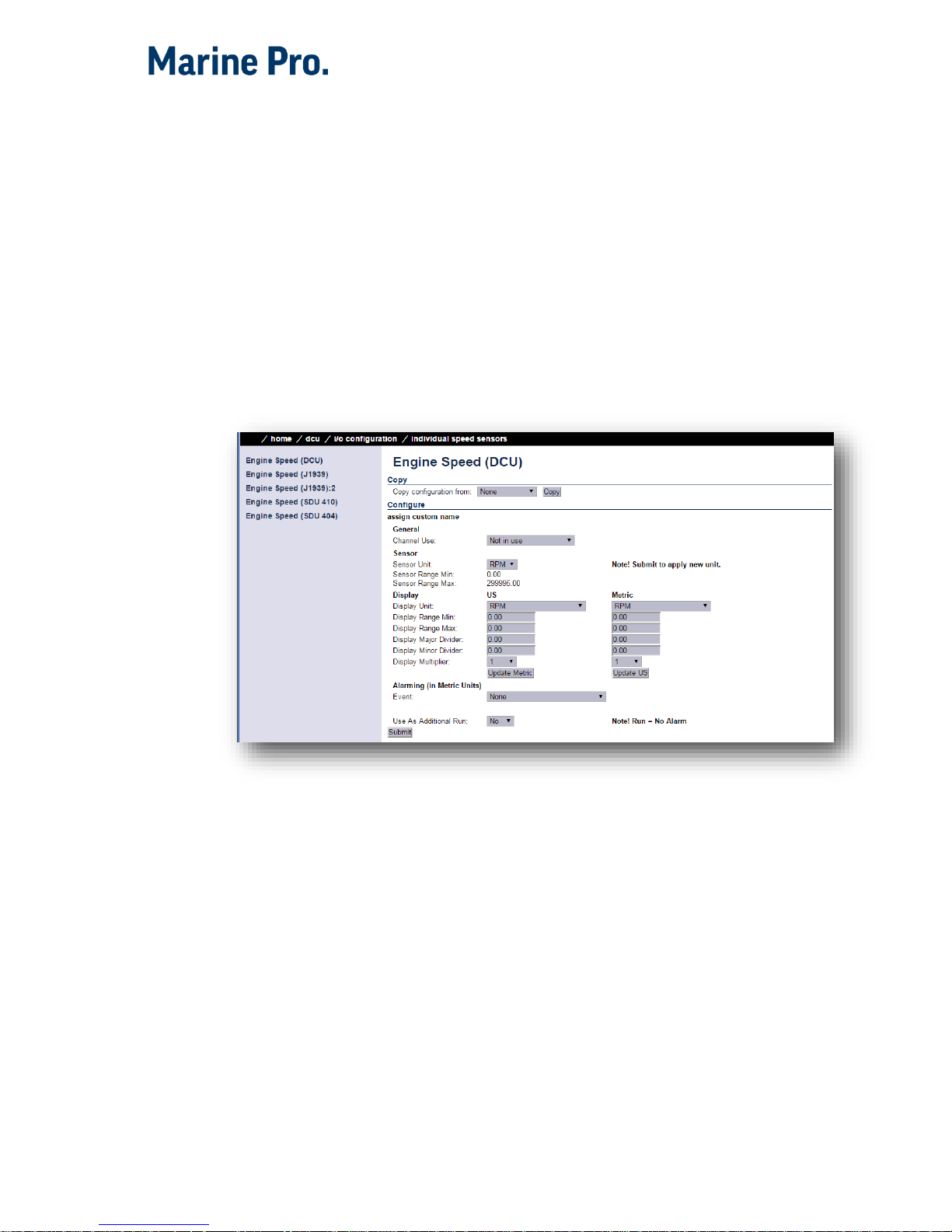
General
Channel use is the selection of where the signal
shall be displayed. Select DCU+RP to display the
instrument in the DCU and in the RP.
Display
The values here define how the instrument widget is
presented.
Display Unit is the signals unit, here RPM.
Display Range Min is the minimum value displayed,
normally 0 (zero).

400 Series Installation and Configuration
DCU 410 Engine Panel Installation 43
Display Range Max is the maximum value
displayed. For an engine running at 1500 rpm
nominally, a typical maximum setting would be
1800 RPM.
Display Major Divider is where the instrument
widget writes an RPM value, normally every 500
RPM.
Display Minor Divider is the ticked marks between
the major divider marks, normally every 100 RPM.
Display Multiplier is the multiplier value. The value
is displayed in the RPM meter.
Overspeed
RPM Overspeed is the setpoint where the DCU
indicates overspeed.
RPM Overspeed Delay is the delay – in milliseconds
– before alarm or shutdown. Typical setpoint is
100ms.
RPM Overspeed Shutdown Enabled is where the
overspeed behaviour is selected.
Select
Yes for the DCU to shutdown the engine.
Select No to disable overspeed shutdown.
Note! Disabling DCU overspeed is valid for the DCU only.
The SDU is able to shutdown the engine.
44 DCU 410 Engine Panel Installation
400 Series Installation and Configuration
Individual Speed Sensors
This is where the display and alarm settings of the three
different types of speed sensors available, can be
configured.
Engine Speed (DCU)
Engine Speed (J1939)
Engine Speed (J1939):2 (If enabled)
Engine Speed (SDU 410)
Engine Speed (SDU 404)

400 Series Installation and Configuration
DCU 410 Engine Panel Installation 45
Engine Load
First, configure either a 4-20mA, 0-5V input or the J1939
PGN 0Xf003, SPN 92. Select then the engine load source
from the dropdown menu. Engine load can now be used
as an additional setting when configuring alarms.

46 DCU 410 Engine Panel Installation
400 Series Installation and Configuration
Gear
First select gear source from the dropdown menu.
In Gear Switch
This is fixed input 95 on the DCU 410
Ahead/Astern Switches
Configure 2 switch inputs as functions
Ahead and
Astern.
J1939 Transmission Current Gear (SPN 523)
The gear settings can now be used as additional settings
for alarms, or shown directly on the DCU. This is done by
going to / home / dcu / user interface.
Select Gear indicator and select to show instead of all ok
symbol.

400 Series Installation and Configuration
DCU 410 Engine Panel Installation 47
Switch
First, select any of the eight switch channels. Then, for
each channel, set the following parameters.
General
Channel Use
Set to
Event if in use. An event can be a warning,
an alarm or a shutdown scenario.
Set to
Silent Event for an active channel, but no
panel alarms. The event will be available on
communication only.
Event
Select from Warning, Alarm, Load reduction or
Shutdown.
Input State
Select NO (normally open), or NC (normally closed).
NO means the contact must close to make the
event, whereas NC means the contact must open to
make the event.
Note!
Normal
denotes a running engine with no
alarm.
Delay Before Event
Choose the desired persistence time before the
event triggers.
Typical values:
Engine Oil Pressure Low: 2 seconds.
Engine Coolant Temp. High: 5-10 seconds.

48 DCU 410 Engine Panel Installation
400 Series Installation and Configuration
Requires Running Engine
Select
Yes if the switch normally changes state
when the engine goes from standstill to running,
or vice versa.
This means the switch will alarm only when the
DCU senses the engine is running.
Typical setting: Set to Yes for all pressure switches.
Several different RPM set points are available.
Requires In-Gear
This means the switch will alarm only when the
DCU has a high input on In-gear input.
Requires Engine Load
This means the switch will alarm only when the
DCU has reached the configured % load.
Initial Delay
Note! Available only if On Run Only is selected.
The switch event is disabled for this many seconds
after the engine is running. After the timer has
elapsed, the channel is enabled.
Typical value: 5-10 seconds.

400 Series Installation and Configuration
DCU 410 Engine Panel Installation 49
Use as Additional Run
If the DCU has one pickup source only, it is
recommended to add an engine oil pressure switch
as an engine running indication.
Note! Do not use any other pressure sensors – or
any other signals – as the engine running
indication!
If two or more engine speed (pickup) sources1 are
in use, then it is recommended leaving this off for
all switches. Set to
No.
If one engine speed source only, locate the engine
oil pressure switch and use this as the Additional
Run signal. Set to
Yes.
1
An engine speed source can be the magnetic pickup connected to the DCU,
the J1939 CAN bus signal connected to the DCU, or the speed signal coming
from the connected SDU 410 safety unit.

50 DCU 410 Engine Panel Installation
400 Series Installation and Configuration
4-20 mA
First, select any of the four 4-20 mA channels. Then, for
each selected channel, set the following.
General
Channel Use
This selects the panel the instrument widget is
displayed on. It is possible to display the
instrument on
o the DCU engine panel, and
o the RP remote panel, or
o a combination of the two.
It is also possible to suppress the alarm events, as
can be seen in the following table overview.
Use
DCU
RP
Config.
outputs
Display
Event
Display
Event
Not in use
Event x x
x
DCU x
x
DCU + Event
x x x

400 Series Installation and Configuration
DCU 410 Engine Panel Installation 51
Use
DCU
RP
Config.
outputs
Display
Event
Display
Event
RP
x x
RP + Event
x x x
DCU+RP
x x x
DCU + RP + Event
x x x x x
Silent Event
x
DCU + Silent Event
x x
RP + Silent Event
x x
DCU + RP + Silent Event
x x x
Display = the signal is displayed in a gauge, or a numerical format.
Event = warning, alarm or shutdown.
Silent Event = no local event, but event on communication only.
Note! Normally, and in most cases, the selection should
be “DCU + RP + Event”, as highlighted in the table above.
This makes sure the channel is displayed in the DCU and
in the RP, if – or when – the RP is installed.
Sensor
Sensor Unit
Select the unit, as printed on the sensor. An oil
pressure sensor might for instance be in Bar or psi.
Sensor Range Min and Max
Select the sensor range values for min and max, as
printed on the sensor.
Display
Display Unit
For the above sensor, select the desired displayed
unit for US and Metric values.
Display Range Min and Max
For the above sensor, select the desired minimum
and maximum values displayed in the instrument,
for US and Metric values.

52 DCU 410 Engine Panel Installation
400 Series Installation and Configuration
Display Major and Minor Divider
For the above sensor, select the desired major and
minor divisions in the instrument, for US and
Metric values. The major divider number is
displayed at each major divider.
Display Multiplier
Select a multiplication factor as necessary.
An instrument with displayed range 0-10,000
would display as 0-1,000 with a multiplication
factor of 10. The multiplication factor is displayed
in the instrument (round gages only).
Update Metric and US
When
the US section has been completed, then the
web server can calculate the other section, and vice
versa.
Note! The application does not round off values. It
is highly recommended to adjust the calculated
values by hand, and set sensible round figure
values.
Alarming
This section is always completed in the currently selected
system unit. To switch unit, simply press the Unit button
on the DCU 410 front panel.
Event
Select the desired combination of warning, alarm
and shutdown. Select “RPM dependent” for a
setpoint that varies with RPM, and complete the
boxes.
Alarm Threshold [unit]
Type in the alarm threshold value, in the correct
units.
Delay After Crossing Alarm Threshold
Set the persistence time before the event. Value is
in seconds.

400 Series Installation and Configuration
DCU 410 Engine Panel Installation 53
Threshold Type
Set the event to appear on a rising (higher) or
falling (lower) signal. A temperature fail is normally
“too high”, and a pressure fail is normally “too
low”. In addition, a high and low threshold set
point can be configured.
Requires Running Engine
Select between one of the following.
o Set
Yes to disable the event when the engine
is not running (enabled when engine is
running only).
o Set
No the enable the event always.
o Choose between other RPM setpoints if
configured in the engine speed
configuration.
See menu / dcu / io configuration / engine speed/
Initial Delay
If
Yes above, set the persistence time after the
engine is running until the channel is enabled.
Requires In Gear
This means the event will alarm only when the DCU
has a high input on the
In Gear input.
Requires Engine Load
This means the switch will alarm only when the
DCU has reached the configured % load.
Use As Additional Run
o If the DCU has one pickup source only, it is
recommended to add an engine oil pressure
switch as an engine running indication.
Note! Do not use any other pressure sensors
– or any other signals – as the engine
running indication!
o Typical setting:

54 DCU 410 Engine Panel Installation
400 Series Installation and Configuration
If two or more engine speed (pickup)
sources2 are in use, then it is
recommended leaving this off for all
switches. Set to
No
.
If one engine speed source only,
locate the engine oil pressure switch
and use this as the Additional Run
signal. Set to
Yes
.
PT100
First, select any of the four PT100 channels.
Then, for each selected channel, set the parameters, as
for the 4-20 mA section, page 50.
24V Inputs
First, select any of the two 24V input channels.
Note! These are
fixed function
inputs, and not the general
switch input channels, as described on page 45.
These two inputs can be given a function from a list of
available functions. The current available functions are:
Local Mode
Remote mode
Backlight 100%
Prelube Override
2
An engine speed source can be the magnetic pickup connected to the DCU,
the J1939 CAN bus signal connected to the DCU, or the speed signal coming
from the connected SDU 410 safety unit.
400 Series Installation and Configuration
DCU 410 Engine Panel Installation 55
Local Start
Local Stop
Local Acknowledge
Local/Remote Acknowledge
In Gear (Ahead)
In Gear (Astern)
Toggle Crank Mode
Activate the function
The function is activated when the input is connected to
24V.
Deactivate the function
The function is deactivated when the input is left open, or
connected to 0V.
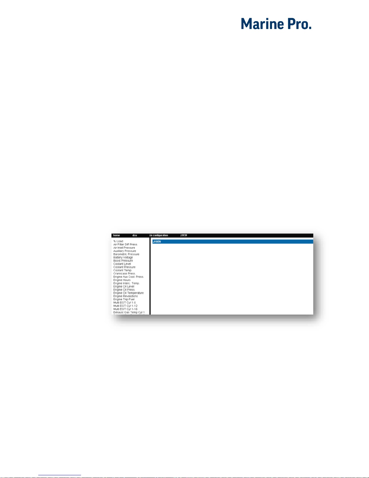
J1939
Select a J1939 CAN bus signal from the list.
Then, for each selected channel, set the parameters as for
the 4-20 mA section, page 50.
Differential
A
differential
channel is a
logical
(not physical) channel,
made up by two physical channels. The physical channels
may be hardwired or from the J1939 CAN bus.

56 DCU 410 Engine Panel Installation
400 Series Installation and Configuration
The differential channel will output the difference
between the two source channels. The sensor unit must
be the same for the two selected source signals, for
instance they must both be bar, and not one bar and one
psi.
Select one of the five differential channels.
Then, select two signals of the same unit type. The
differential channel result can be assigned to an
instrument widget.

400 Series Installation and Configuration
DCU 410 Engine Panel Installation 57
Average
An
average
channel is a
logical
(not physical) channel,
made up by two or more physical channels. The physical
channels may be hardwired or from the J1939 CAN bus.
The differential channel will output the average between
the two or more source channels. The sensor unit must
be the same for the selected source signals, for instance
they must both be bar, and not one bar and one psi.
Select one of the three differential channels.

58 DCU 410 Engine Panel Installation
400 Series Installation and Configuration
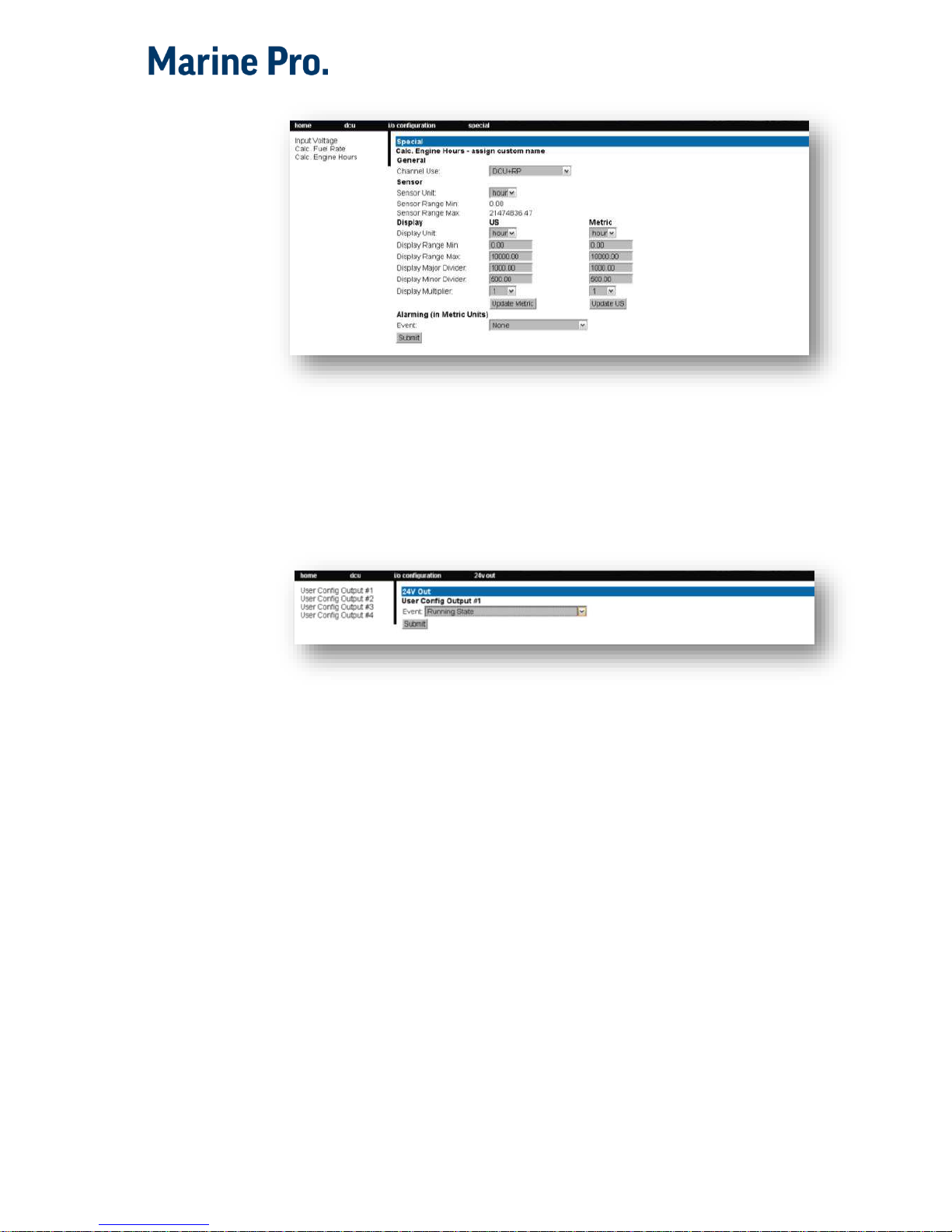
Special
These are a group of “special” signals as follows.
Input Voltage
This is the supply voltage
used in the DCU
, and is the
same as the voltage supplied out on terminals 5-6.
The Input Voltage is the channel that monitors
either
Supply or Supply 2, whichever the DCU chooses.
Set the desired ranges for use in a gauge or bargraph.
For an alarm, set an event and complete the dialog.

400 Series Installation and Configuration
DCU 410 Engine Panel Installation 59
Calculated Fuel Rate
The DCU can calculate the fuel consumption and present
an approximate figure.
Note! The Boost Pressure MUST be connected to 4-20 mA
channel #2.
Select the channel and configure accordingly.
Calculated Engine Hours
If the engine hours are not sourced from the J1939 CAN
bus, it is being calculated internally by the DCU.
The appearance of the counter is configured in this
dialog.
It is possible to set an alarm or other event connected to
the engine hours.
60 DCU 410 Engine Panel Installation
400 Series Installation and Configuration
Instantaneous Fuel Economy (DCU)
The DCU has seven 24V outputs. The function on the
output is configured here.
Analog Modbus
The DCU has 50 analog Modbus registers that users can
write to from external devices. The values can be used as
signal sources, and set up in the same way as 4-20 mA
sensors. Please see the communication manual for further
technical description of the registers.
Digital Modbus
The DCU has 500 digital Modbus registers that users can
write to from external devices. The values can be used as
signal sources, and set up in the same way as switch
sensors. Please see the communication manual for further
technical description of the registers.

400 Series Installation and Configuration
DCU 410 Engine Panel Installation 61
EGT (Exhaust Gas Temperature)
Cylinder Deviation Event
The deviation is the difference between the cylinder value
and the average value. Deviation is positive (above zero) if
the cylinder value is above the average, and negative
(below zero) if the cylinder value is below the average.
Turbo Deviation Event
The deviation is the difference between the turbo value
and the average value. Deviation is positive (above zero) if
the turbo value is above the average, and negative (below
zero) if the turbo value is below the average.
24V Outputs
The DCU has seven 24V outputs. The function on the
output is configured here.
Select one of the seven 24V output channels.
Then, for each channel, select the desired function.
Relays
The DCU has two inbuilt potential free relay contacts,
which can be assigned a function.

62 DCU 410 Engine Panel Installation
400 Series Installation and Configuration
Select one of the two relays. Then, for each channel,
select the desired function.
Speed Relays
A Speed Relay is a relay that activates on a certain engine
speed rpm, and deactivates at the same rpm-1.
For instance, speed relay #1 can be configured to activate
at 1200rpm, and will then deactivate at 1199rpm.
Set Event Log to Yes to create an event in the log when
the speed relay activates.
The Speed Relay can be assigned to any configurable
output.
J1939 Outputs
The DCU can transmit J1939 on Idle Bus.
J1939 outputs.
Each channel can be configure to transmit different
SPN/PGN signals.
Special
Transmit Nominal speed to engine (SPN 515)
Start Stop over J1939 (SPN 3452)

400 Series Installation and Configuration
DCU 410 Engine Panel Installation 63
Home – DCU – Interface Design
This is the section where templates are populated with
the already configured signals from the I/O section.
A
page
on the DCU is built up with a
template
. A
template
has several
slot
positions. Each
slot
position can hold a
widget
type, which in turn can be assigned a
signal
.
Configuration
Chose if the DCU is to display green section on bars when
the signal is within parameter.
Option for displaying J1939 switchover from J1939#1 to
J1939#2.
Pages
This is where the configuration of the different pages is
done.
In the example below, three pages are created.
Insert a new Page
Choose whether the new page is to appear before or after
an existing page, then press the Insert Page button. The
pages will be renumbered.

64 DCU 410 Engine Panel Installation
400 Series Installation and Configuration
Choose a Template
A range of templates will be presented. Choose a
template and start populating the page with predefined
signals.
The chosen template will appear at the bottom of the
screen. Select a signal and
Submit it to clear away the
other templates.
Delete a Page
First Select the page, and then press the
Delete button.
The pages will be renumbered!
Edit the Signal
If the chosen signal is not correctly configured, press Edit
Signal to edit it.
RP Home View Configuration
The RP 410 home page displays certain parameters from
each connected DCU.
This is configured in each DCU.

400 Series Installation and Configuration
DCU 410 Engine Panel Installation 65
Home – DCU – Start/Stop/Prelube
Settings
There are several settings for Start/stop on the DCU.
General
The DCU Engine Start/stop can be configured to three
different modes.
Exclusive, the DCU has exclusive control of the
engine start/stop. Warnings will be given for
unexpected state changes.
Shared, the DCU has shared control of the engine
start/stop. No warnings will be given for
unexpected state changes.
Deactivated, the DCU is not in control of the
engine start/stop. No warnings will be given for
unexpected state changes.

66 DCU 410 Engine Panel Installation
400 Series Installation and Configuration
The Start and Stop button can be configured to be
Latched
or
Momentary
.
Note! The selection is valid for the Start and Stop button.
Disable Local Start/Stop Buttons
Disable the local start/stop buttons on the DCU.
Hold Button to Start/Stop
Set to Yes for a momentary Hold-To-Start/Stop
button. The button must be pressed until the
engine has started/stopped.
Set to
No for a latched button. The button needs to
be pressed momentarily, after which the DCU
completes the start/stop sequence as if the button
was held continuously.
Typical setting:
No (gives a latched button operation, which is
normally preferred).
Allow E-Start
This will give the option of starting with prelube override
and shutdown override.
Only Allow Local Start In Local or Emergency Mode
Typical setting is
Yes.
If setting is
No, local start/stop will work in any mode of
operation.
Allow Automatic Start/Stop in All Operation Modes:
Default setting
NO.
Prohibit Crank Above RPM Threshold [RPM]
Select between
Not in use

400 Series Installation and Configuration
DCU 410 Engine Panel Installation 67
5 RPM
300 RPM
Prelube
The DCU can prelube the engine at certain regular
intervals, and/or before start.
Prelube Type – Fixed Time
This will activate prelube on terminal 84 (Prelube Act.) for
a fixed time, after which the DCU will crank the engine
with terminal 83 (Crank).
Prelube Time
Set the number of seconds the DCU shall prelube before
start.
Typical setting:
5-30 seconds
Prelube Type – Until Pressure
This will activate prelube on terminal 84, then await the
activation of the Prelube Complete signal on terminal 86.
Prelube Timeout
The DCU expects to receive the Prelube Complete signal
on terminal 86 within this timer period.
Typical setting:
5-30 seconds

68 DCU 410 Engine Panel Installation
400 Series Installation and Configuration
Override Allowed
Select if a prelube should be possible to manually
override, to continue the start sequence with an
incomplete prelube sequence.
Note! The override is done in the DCU menu – Settings –
Prelube Override.
Action Upon Timeout
Select the action if the Prelube Timeout timer elapses.
Select
Allow Start to continue cranking the engine
anyway.
Select
Abort Start to abort the start sequence. The
DCU will indicate with a Prelube Failure alarm.
Oscillating
The DCU can prelube the engine continuously, in a never
ending sequence. The sequence is disabled while the
engine is running.
Oscillating Enabled
Set to Yes to enable oscillating prelube.
Oscillating On Time
Set the number of seconds the DCU shall lubricate the
engine.
Typical setting:
60 seconds
Oscillating Off Time
Set the number of minutes between each lubrication
action.
Typical setting:
60 minutes
Oscillating Feedback
Set this if a feedback from the oscillating feedback is
required. The feedback will have to be connected to
prelube complete.

400 Series Installation and Configuration
DCU 410 Engine Panel Installation 69
Oscillating Feedback time
Set the timer for oscillating feedback failed warning.
Auto Start/Stop
The DCU can start the engine automatically. The following
conditions must be met:
Terminal 88 (Automatic Mode) must be high (24V),
or the DCU menu item Settings – Automatic must
be selected.
Terminal 89 (Automatic Start) must be high (24V).
This triggers the start sequence.
Initial Start Delay
When the start sequence activates, this timer must elapse
before the DCU will do the first start attempt.
Typical setting:
1 second
No. of Start Attempts
The total number of start attempts.
Typical setting:
3 attempts
Prelube Before Each Start Attempt
Select Yes to prelube before each start attempt.
Select
No to prelube before the first attempt only.
Starter 1 / Starter 2
Cranking Time
The time the starter engine is engaged.
Typical setting:
5-7 seconds
Delay Between Start Attempts
If the engine did not start after the previous attempt, it
will delay this many seconds until it does the next start
attempt.

70 DCU 410 Engine Panel Installation
400 Series Installation and Configuration
Note! The timer starts when the engine rpm is less than
5rpm.
Typical setting:
5-7 seconds
Starter type
Configure
the type of starter connected to the crank
output
.
If configured a 2nd starter, a 2nd crank output has to be
configure, see 24V outputs in
/ home / dcu / I/o configuration / 24v output functions
Automatic Stop
The DCU can stop the engine automatically. The following
conditions must be met:
Terminal 88 (Automatic Mode) must be high (24V),
or the DCU menu item Settings – Automatic must
be selected.
Terminal 90 (Automatic Stop) must be high (24V).
This triggers the stop sequence.
Delay Before Disconnecting Generator Breaker
When the automatic stop condition is applied, the DCU
will wait this many seconds, and then it will activate a
signal to disconnect the generator breaker, if any.
The Disconnect Generator Breaker signal is not a standard
output signal, and must be configured to a suitable 24V
or relay output.
Typical setting:
1-60 seconds
Cooling Time
After the previous timer has elapsed, the engine will
continue to run (with no load) for this amount of time to
cool down. When the timer has elapsed, the DCU will stop
the engine.
Typical setting:

400 Series Installation and Configuration
DCU 410 Engine Panel Installation 71
1-5 minutes
Stopping
Configurable settings for stopping state.
Stopping Time is the timer for the duration of the normal
stopping state.
Safety Stopping Time is the timer for the duration of
safety stopping, where the DCU/SDU has lost the running
state via either Pickup/J1939 or other additional run
signals.

72 DCU 410 Engine Panel Installation
400 Series Installation and Configuration
Home – DCU – User Interface
Language
In this section, the signal descriptions can be manually
translated to other languages.
All Signals
Press All Signals to display all signals available in the
DCU.
The page displays three rows of signal text. The first row
is the
English Default
text, the second row is the
English
Used
text, and the third row is the 2nd language.
English Default
English Used
2nd Language
Engine Oil Press.
Engine Oil
Pressure
Motoroljetrykk
Engine Speed
[default]
Motorturtall
Note! The English language is always available in the DCU
and the RP.
The text [default] means that the English default text
(column 1) will be used. Select any [default] text to
change the signal text description.
Enabled Signals Only
This is the same as All Signals, except that only signals
that are in use are listed.

400 Series Installation and Configuration
DCU 410 Engine Panel Installation 73
Service
The four Service intervals will indicate with a text. The
default text can be changed.
As above, press the [default] text to change the default
text.
Buzzer
Buzzer Off
Select
Yes to suppress the buzzer automatically.
The buzzer will activate as before, but the DCU will
automatically silence after 5 seconds.
Gear Indicator
Show Gear Indicator Instead Of All Ok
Select
Yes to show the Gear Indicator instead of All Ok
symbol.
Home – DCU – Engine Model
Engine Name
Type the name of the engine, for example “Auxiliary”.
Note! The last two digits in the DCU IP-address becomes
the engine number. If the IP-address is 192.168.0.110,
then the engine is in this example is named “Auxiliary
#10”.
Home – DCU – Service Interval
View Service Status
This will list the number of hours until next service is due.

74 DCU 410 Engine Panel Installation
400 Series Installation and Configuration
Configure
Up to four different timers can be configured to indicate it
is time for engine service.
The default text “Service 1” can be changed by selecting
the a
ssign custom name
link.
Service Enabled
Select Yes to enable this service interval timer.
Next Service At
Select the hour counter value in the DCU for the
first
service. Note that this happens only one time.
This is useful if the first service should have a shorter
interval than the regular service interval.
Then Every
Select the service interval in hours. The DCU will indicate
every time this number of hours has elapsed.
Example
Current DCU hour counter is 123 hours.
Next Service At: 150 hours
Then every: 250 hours
The first service notification will appear in 27 hours, then
every 250 hours. All hours are engine running hours.
Home – DCU – Communication
Network Communication
Set the IP-address for the DCU.

400 Series Installation and Configuration
DCU 410 Engine Panel Installation 75
Make sure the IP-address is unique on the network. If
installing the DCU in an already established ship Ethernet,
consult the network manager to obtain an IP-address.
Note! The last two digits becomes the engine number, as
part of the engine name.
Example
The Engine name is “Auxiliary”, the IP-address is selected
as 192.168.0.110. The engine name then becomes
“Auxiliary #10”.
J1939/CANopen
The DCU has an inbuilt CANopen communication
interface. This port can be used as a second J1939
interface.
Baudrate
Set the Baudrate (communication speed) for the CANopen
interface the DCU is connected to on COM 5.
Typical setting:
125kbps
Node ID
Set the Node ID for the DCU CANopen interface.
Typical setting:
Unique integer number from other CANopen nodes
on the same network.
Download EDS file
Select this to download an EDS file.
Modbus RTU
The DCU has an inbuilt Modbus RTU communication
interface.
Power
Power the optocoupled interface with 24VDC.

76 DCU 410 Engine Panel Installation
400 Series Installation and Configuration
Modbus Parameters
Baudrate: 19200
Databits: 8
Stop bit: 1
Parity: Even
Address
Set the Modbus ID number. The number can be any
integer in the range 1-32, and must be unique on the
network.
J1939 Configuration
Source Address
Set the address for the J1939 communication.
Default setting is
0xf2.
Request Address
Setting which address to use for requesting an address
for the DCU,
0xFF is for broadcast.
Default setting is 0x00.
Allowed Address
Setting for which addresses the DCU will use to present
the configured J1939 signals.
Default setting is Show All.
By selecting
No, the user can define up to 10 addresses to
be used by the DCU.
Allowed DM1 Address
Setting for which addresses the DCU will use to present
the DM1 fault messages.
Default setting is Show All.
By selecting
No, the user can define up to 10 addresses to
be used by the DCU.

400 Series Installation and Configuration
DCU 410 Engine Panel Installation 77
J1939:2 Request Address
The secondary J1939 channel has to be enabled to be
used as a J1939 interface.
Default for this interface is CANopen.
Setting which address to use for requesting an address
for the DCU,
0xFF is for broadcast.
Default setting is 0x00.
J1939:2 Allowed Address
The secondary J1939 channel has to be enabled to be
used as a J1939 interface.
Default for this interface is
CANopen.
Setting for which addresses the DCU will use to present
the configured J1939 signals.
Default setting is
Show All.
By selecting
No, the user can define up to 10 addresses to
be used by the DCU.
J1939:2 Allowed DM1 Address
The secondary J1939 channel has to be enabled to be
used as a J1939 interface.
Default for this interface is CANopen.
Setting for which addresses the DCU will use to present
the DM1 fault messages.
Default setting is
Show All.
By selecting
No, the user can define up to 10 addresses to
be used by the DCU.

78 DCU 410 Engine Panel Installation
400 Series Installation and Configuration
Home – DCU – Miscellaneous
Alarm Configuration
The DCU has a primary and a secondary power supply
input.
If the secondary input is not in use, the low voltage alarm
on this input needs to be disabled.
Primary Power Fail Alarm Enabled
Set to No to disable the alarm. This is used when
there is no connection to the primary supply.
Set to
Yes to enable the alarm. This is used when
there is a connection to the primary supply.
Typical setting:
Yes. Normally, there shall be a separate supply
connected to the primary supply.
Secondary Power Fail Alarm Enabled
Set to No to disable the alarm. This is used when
there is no connection to the secondary supply.
Set to
Yes to enable the alarm. This is used when
there is a connection to the secondary supply.
Typical setting:
Yes. Normally, there shall be a separate supply
connected to the secondary supply.
J1939 CAN bus Broken Wire Alarm When Engine Not
Running
Default setting is
No.
J1939 CAN bus Nodes Lost Warning Enabled:
Default setting is No.
Erratic J1939 Data Warning Enabled:
Default setting is
No.

400 Series Installation and Configuration
DCU 410 Engine Panel Installation 79
J1939 CAN bus Red Lamp Severity
A red lamp severity DM1 fault can be configured to give
an alarm, or shutdown.
J1939 CAN bus Amber Warning Lamp Enabled
An amber warning lamp DM1 fault can be configured to
give an alarm.
RP Lost Warning Enabled
Configure if the DCU is to give an alarm if the DCU loses
network connection to an RP panel.
Default setting is
No.

80 DCU 410 Engine Panel Installation
400 Series Installation and Configuration
Counters
The DCU calculates and stores engine running hours.
Counter Source
Set the counter source to be either from the J1939 CAN
bus, or from a locally generated counter in the DCU.
Update Local Engine Hours
This updates the local counter to any new value.
Current Engine Hours
Set a new total engine hour setting.
Note! If the Counter Source is J1939, then this setting will
be overwritten when the DCU receives new data on the
J1939 CAN bus.
Fuel Consumption
By inputting the Nominal RPM, Nominal Consumption,
Boost Pressure and Idle/No-Load Constant, the DCU can
calculate an estimated fuel consumption value.

400 Series Installation and Configuration
DCU 410 Engine Panel Installation 81
Acknowledge Configuration
The DCU has two different settings for acknowledge
function of alarms.
Only Acknowledge Visible Events.
By setting this parameter to yes, the DCU can only
acknowledge events that are visible in current view of the
alarmlist when using acknowledge all function.
Disable Remote Acknowledge
Enable or disable remote acknowledge.
Operation Mode Locked to input
Disabling local start/stop buttons and the ability to
change operation modes on the DCU. Modes of operation
and start stop can only be activated by the terminal
inputs on the rear of the DCU.
Event Log
The DCU has an inbuilt event log.
Everything
This displays a list of all events in chronological order.
Alarms Only
This displays a list of all warning, alarm and autostop
(shutdown) events.
User Interaction Only
This displays a list of all button presses.
• Local Start/Stop Button
•
Local Alarm List Button

82 DCU 410 Engine Panel Installation
400 Series Installation and Configuration
• Service Complete Button
•
Service Remind me later Button
Commands Only
This displays a list of all remote commands to the DCU.
Events Only
This displays a list of all events that are not alarms.
• Automatic Mode input (terminal 88, or configurable
input configured as Automatic
Mode).
• Speed Switches
• Prelube Override
• Power On/Off
• Crank Without Prelube
• Start Disabled input (terminal 87)
Sequence Only
The following events are logged as Sequence.
• Automatic Start/Stop (terminal 89/90)
• Remote Start/Stop (terminal 91/92)
• Remote Acknowledge (terminal 93)
• Remote Start/Stop by command (RP and Modbus)
• Remote Acknowledge by command (RP ad Modbus)Save
As…
The current list of events can be saved into a text file.
Suppress DM1 Fault
The ability to suppress combinations of SPN and FMI
appearing on the J1939 interface.

400 Series Installation and Configuration
DCU 410 Engine Panel Installation 83
Engine Application Configuration
Configuration of the Engine Application and displays
which modes of operation are available for said
application.
Shutdown Override Configuration
Transmit Shutdown Override to SDU
Transmits the shutdown override command from the DCU
to the SDU, does not affect the transmitting of shutdown
override from SDU to DCU.
Shutdown Override from J1939
The parameter to enable shutdown override from J1939.

84 DCU 410 Engine Panel Installation
400 Series Installation and Configuration
Factory Reset
Command for factory resetting the DCU.
Home – DCU – Language
This is a shortcut link to the Language section.

400 Series Installation and Configuration
DCU 410 Engine Panel Installation 85
Communication Interface List
The DCU Communications Interface List covers the
communication interface for
Modbus RTU (COM 3)
The Communication I/O list is available online from one
of the following links
Click
here, or
http://goo.gl/5qk4YH
DCU 410 and DCU 408 capacity
Functionality and content highlights
2 x 24 V DC redundant supply
5.7" TFT colour Screen (not DCU 408)
4 x PT100 input channels
4 x analogue input channels, 4-20 mA
8 x switch input channels
1 x tacho input channel
1 x Ethernet incl. Modbus/TCP
1 x RS-485 Modbus RTU
1 x J1939 CAN interface
1 x CANopen/J1939#2 interface
2 x configurable relay outputs
7 x configurable 24 V outputs
1 x common alarm relay
RP 410 Remote Panel link (TCP/IP)
SDU safety unit link
RIO expansion I/O link
MK-14 expansion relays link
Internal web server for configuration and support
Password protected configuration
User selectable units (U.S. / Metric)
True multilingual
Sophisticated alarm configuration
Supply voltage monitoring and alarm

86 DCU 410 Engine Panel Installation
400 Series Installation and Configuration
Extensive alarm list with ECM diagnostics
SPN/FMI codes, translated into current selected
language
Log of all events
Configurable prelube functionality
Service interval timers
Ambient light sensor for automatic backlight
adjustment
Calculated approximate fuel consumption values
Certified by major classification societies
Total I/O capacity
The I/O capacity of the DCU can be expanded using one
or more of the RIO units, see page 100.
Signal type
Standard
Max
4-20 mA
4
40
PT100 4 36
Switch Inputs
8
24+16
Thermocouple K-type
0
8+20
Configurable Relays
2
24
Configurable 24V Out
4
12
0-5V Inputs
0
4
J1939 Channels
20 pages
20 pages

400 Series Installation and Configuration
RP 410 Remote Panel Installation 87
RP 410 Remote Panel
Installation
Location
The RP is normally located in the engine control room and
wheelhouse.
The RP should be mounted at about eye level and the user
should have easy access to the touch screen and buttons
on the panel.

88 RP 410 Remote Panel Installation
400 Series Installation and Configuration
General Overview
The RP 410 is the remote panel for the DCU engine
control unit. It is connected to the Ethernet network
together with the DCU unit, and will – after a network
search – locate all connected DCU units, and update its
configuration accordingly.
No configuration is necessary on the RP 410. Just connect
it to the network and set user preferences using the menu
interface.
One RP 410 can control and monitor up to eight DCU
units, and there can be an “unlimited” number of RP 410
units connected on the same network.
In an installation where multiple (more than one) RP 410
units are installed, the RP 410 units makes sure only one
RP 410 has command of a single DCU at any one time.

400 Series Installation and Configuration
RP 410 Remote Panel Installation 89
Electrical Connections
A minimum installation requires only power supply to
terminals 1-2, and an Ethernet cable to the Ethernet
switch.
Wire Terminal Layout Overview
Power supply input /auxiliary power output
1
+24VDC Primary Supply, 1A
In 2 0V Primary Supply
In
Switch Inputs
3
+24VDC Switch Power output, 0.2A
Out 4 Global Acknowledge
In 5 Local Silence
In 6 Switch 3 <reserved>
In 7 Switch 4 <reserved>
In
Relays
8
Relay 1 NC
Partial/Full Active
Station
In/Out
9
Relay 1 Common
In/Out
10
Relay 1 NO
In/Out
11
Relay 2 NC
Acknowledge Button
(1 sec pulse)
In/Out
12
Relay 2 Common
In/Out
13
Relay 2 NO
In/Out
14
Relay 3 NC
<reserved>
In/Out
15
Relay 3 Common
In/Out
16
Relay 3 NO
In/Out
17
Relay 4 NC
<reserved>
In/Out
18
Relay 4 Common
In/Out
19
Relay 4 NO
In/Out
Modem Interface – COM 1
20
Tx
Out
21
Rx
In
22
RTS
Out
23
CTS
In

90 RP 410 Remote Panel Installation
400 Series Installation and Configuration
24
0V
In
GPS Interface – COM 2
25
Tx
Out
26
Rx
In
27
0V
In
28
Protective Earth
-
Rear Lid Graphical Layout
RP 410 rear lid layout
System Configuration Icon selections
To get to the system configuration, do as follows.
1. Press the
Home button
2. Select the Menu touch button
3. Select the
Configuration icon
4. Select the
System Configuration icon

400 Series Installation and Configuration
RP 410 Remote Panel Installation 91
Type the password to get access to the submenu.
Note! The factory default password is 1234. If this
password does not work, a new password has been set.
Lost Password
The RP will issue an encrypted code if a wrong password
is entered.
This encrypted code can be sent to your distributor, who
will be able to obtain the original password.
Change Password
The default password is 1234.
In order to preserve the configuration from unauthorized
access, the password should be changed. Enter a 4-digit
code to secure the configuration, and keep the password
in a safe place.
Station Priority
Different priorities are used in conjunction with multiple
RP remote panels. If only one RP is installed, the priority
should be set to 1.
Society regulations require that only one remote panel
can control an engine, at any given time.
In the RP, the panel currently controlling an engine is
called the Active Station for that engine.
There are three RP priorities.
Priority 1 panels will always become an active
station if required. It will take the engine control
from panels with priority 1, 2 or 3.
Priority 2 panels must ask for engine control.
Priority 1 and Priority 2 panels with engine control
must agree to the handover.
Priority 3 panels can never do engine commands.

92 RP 410 Remote Panel Installation
400 Series Installation and Configuration
RP Priority Summary
The following table summarizes the priority scheme.
Priority 1
Typically highest priority
control station, like the engine
control room.
Also if one RP in the network
only.
Priority 2
Typically lower priority control
station or wheelhouse.
Priority 3
Typically in a possible public
area, or where commands shall
not be possible.
Take
command
Can always take command
from the current active panel;
no question asked.
Note! If the operator tries to
execute a command, and the
panel is not the active station,
it will immediately become the
active station and execute the
command.
Can take command from active
station panels with priority 1 or
2 after confirmation at the
current active panel.
Disabled.
This priority can never be an
Active Station.
Release
command
Will handover command to any
other priority 1 panel
immediately.
May handover command
to priority 2 panels, depending
upon Confirmation Timeout
Priority.
Will handover command to any
other priority 1 panel
immediately.
May handover command to
priority 2 panels, depending
upon Confirmation Timeout
Priority.
If in command, will handover
command to priority 1 or 2
panels immediately.
Make sure to select a priority for the RP remote panel that best fits its use.
Timeout Behavior
This function is used in conjunction with multiple RP
remote panels and active station handover.
Example: An RP panel X is currently the active station for
an engine.
If an RP panel Y is requesting active station for an engine,
and the operator at RP panel X does not respond to the
request within the defined period of time, then it is
assumed there is no operator at RP panel X.
In these instances, the RP panel X can be configured to
automatically either release its active station status for
the engine, or deny the request altogether.
Note that either action takes place after the defined
timeout.

400 Series Installation and Configuration
RP 410 Remote Panel Installation 93
DCU Alarms
If disabled, no alarms will be present on this RP station.
This is typically use in the wheelhouse, if there is another
RP panel in a manned engine control room.
DCU Acknowledge
If disabled, alarms cannot be acknowledged on this RP
station.
Note! If DCU Alarms is disabled then DCU Acknowledge is
also disabled.
Station Location
Select the current location for this panel.
This is used in conjunction with multiple RP remote
panels, where there is a need for the other panels to see
which panel is asking to become the active station for a
certain engine.
Functional Outputs
If the optional relay board module MK-14 is connected to
the RP port COM 5, certain functions can be configured to
appear at these relays.
See page 108 for a closer description of the MK-14
module.
IP-address
The IP-address for the RP can be changed here.
Note! Make sure the new IP-address is unique on the
network.

94 RP 410 Remote Panel Installation
400 Series Installation and Configuration
DCU Connections
This lists the currently connected DCU’s. Press Search to
make the RP search for all connected DCU units on the
network.
When an RP is correctly connected to one or more DCU
units, the RP is automatically updated with the same
instruments and pages as in the DCU.
Ignore certain engines
If a DCU appears on the list that is unwanted, select the
Ignore checkbox for that engine. The DCU (that engine)
is now ignored by the RP.
Cameras
Select the camera type and set the IP-address (as printed
on the camera) for the camera. Up to four cameras can be
installed, and they must have unique IP-addresses.
Camera position
The four cameras are displayed in the RP screen at the
following positions.
Camera 1
Camera 2
Camera 3
Camera 4
IP-address
The reserved camera IP-address range is 192.168.0.220
to 192.168.0.239.
Camera type
Select the correct camera type.
Lock
Select this icon to logout from the System Configuration
section. The password must be entered to re-enter.

400 Series Installation and Configuration
RP 410 Remote Panel Installation 95
Note! If the System Configuration section is not manually
locked, the RP will lock it automatically anyway after a
timeout.
Reset to Factory Defaults
Select this to reset the RP panel to its factory default
values.
Note! After reset, the factory default password is set to
1234.
After reboot, the RP will start up with the startup wizard
questions, and a new password can be set.

96 Add-On Modules
400 Series Installation and Configuration
Add-On Modules
Different expansion units are available, as follows below.
SDU 410 Safety Unit
The SDU 410 Safety Unit operates fully independent from
the DCU, but has a communication link.
Note! The SDU is mandatory in type approved
installations.
The SDU has a built-in web server and can be configured
independently, or it can be configured using the webserver in the DCU.
The configuration is stored internally, as well as in the
DCU configuration file.
Capacity
A maximum of eight switch channels are available to
command a shutdown.
All eight channels are monitored for a broken wire or a
short circuit, to 0V or 24V, on any of the two terminals.

400 Series Installation and Configuration
Add-On Modules 97
Wire Terminal Layout Overview
Power supply inputs
1
+24VDC
In 2 0V
In 3 Ground
-
Shutdown Coil
4
+24VDC
Out 5 0V
Out
6
+24VDC, Supply
In
7
0V, Supply
In
Pickup input (Tacho / Speed input)
8
Shield
- 9 #1 Pickup A
In
10
#1 Pickup B
In
11
Shield
-
12
#2 Pickup A
In
13
#2 Pickup B
In
Shutdown Relay
14
Shutdown NC
Out
15
Shutdown Common
In
16
Shutdown No
Out
Crank Cut-off Relay
17
Crank Cut-off NC
Out
18
Crank Cut-off Common
In
19
Crank Cut-off NO
Out
Buzzer
20
Buzzer Out
Out
21
Buzzer In
In
Fault Relay
22
Fault Relay NC
Out
23
Fault Relay Common
In
24
Fault Relay NO
Out
 Loading...