

Page 1
Publication P/N 1006494
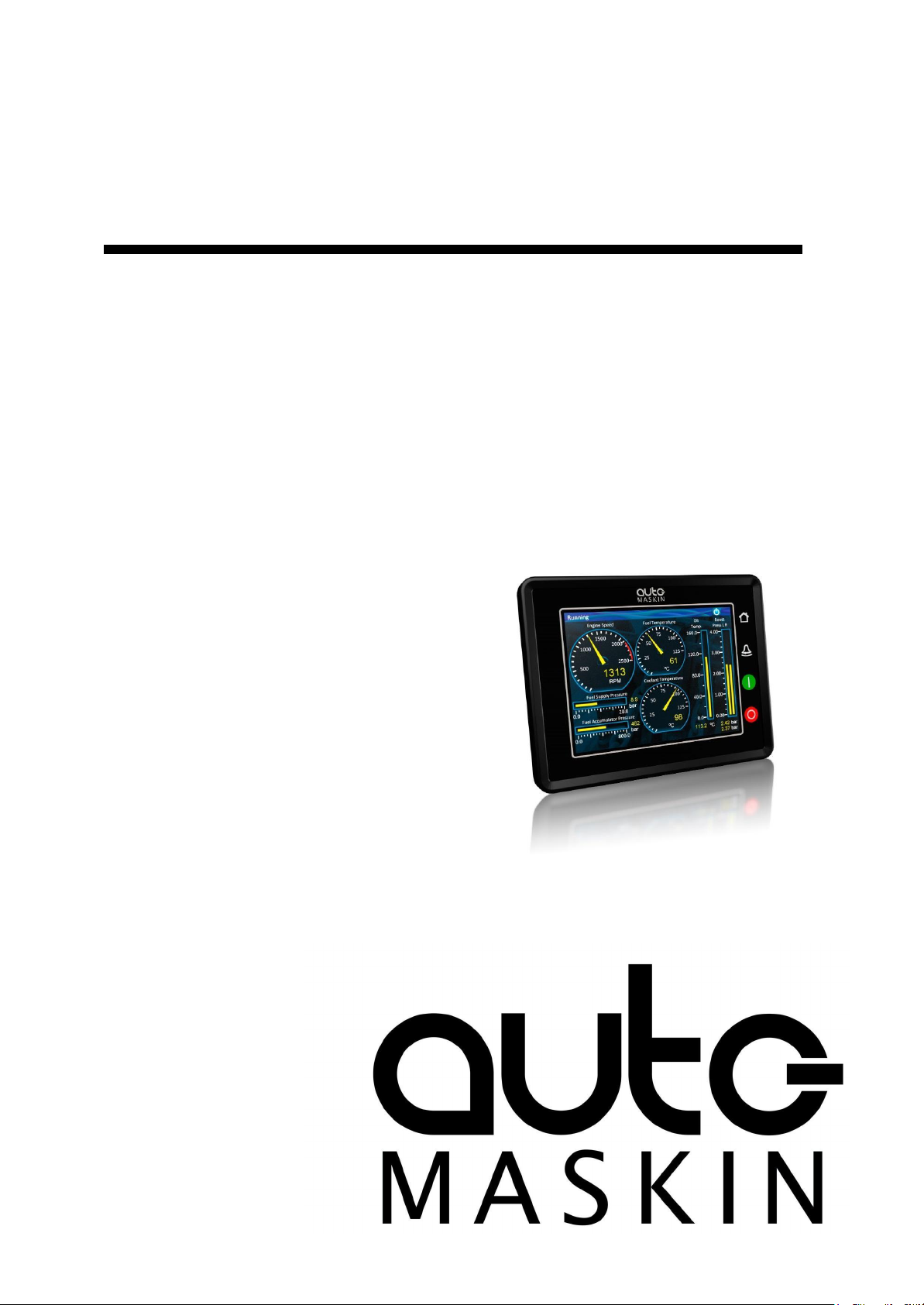
User Manual
Marine Pro
200 Series
DCU 210E Engine Controller, P/N 1006475
DCU 208E Engine Controller, P/N 1006477
RP 210E Remote Panel, P/N 1006476
RP 220E Remote Panel, P/N 1006472
RP 206E Remote Panel, P/N 1006478
Page 2

1 Preface 3
1.1 About this Manual 3
1.2 Responsibilities 3
1.3 Revisions 3
2 Ordering Information 4
3 Overview of the 200 series 4
3.1 DCU 210E Engine Controller 4
3.2 DCU 208E Engine Controller 4
3.3 RP 210E/220E Remote Panel 5
3.4 Ethernet Switch 5
3.5 Expansion 5
4 DCU 210E Engine Controller 5
4.1 First Power On 5
4.2 Configuration Dependency 6
4.3 Main Elements of the Touch Screen 6
4.3.1 Screen Navigation and Hot-spots
6
4.4 Panel Buttons 7
4.5 Screen Layout 8
4.5.1 Status Bar Symbols 8
4.6 Start Engine 9
4.6.1 Latched Start 9
4.6.2 Hold-to Start 10
4.6.3 E-Start 10
4.7 Stop Engine 10
4.7.1 Latched Stop 10
4.7.2 Hold-to Stop 11
4.8 Alarm List 11
4.8.1 Indication 11
4.8.2 Enter the Alarm List 11
4.9 Menu 12
4.9.1 Settings 12
4.9.2 Screen Backlight 14
4.9.3 Log & Counters 14
4.9.4 Controls 15
4.9.5 Help 16
5 RP 210E/220E/206E Remote Panel 16
5.1 Introduction 16
5.1.1 Similarities with the DCU 210E
17
5.2 Status Bar Symbols 17
5.3 Other Symbols 17
5.4 Menu 17
5.4.1 Active Station 18
5.4.2 Settings 18
5.4.3 Camera 19
6 The Alarm List 19
6.1 Filter Alarms 20
6.2 Silence the Buzzer 20
6.3 Acknowledge a Single Alarm 20
6.4 Acknowledge All Alarms 20
Page 2 (20)
Table of contents
Page 3
1 Preface
Work on the low-voltage circuit should only be carried out by qualified and
experienced personnel.
Installation or work on the shore power equipment must only be carried out by
electricians authorized to work with such installations.
It is the sole responsibility of the installer to ensure that the installation work is
carried out in a satisfactory manner, that it is operationally in good order, that the
approved material and accessories are used and that the installation meets all
applicable rules and regulations.
Auto-Maskin continuously upgrades its products and reserves the right to make
changes and improvements without prior notice.
The crossed-out wheeled bin symbol indicates that the item should be
disposed of separately. The item should be handed in for recycling in
accordance with local environmental regulations for waste disposal.
By separating a marked item, you will help reduce the volume of waste
sent to incinerators or land-fill and minimize any potential negative impact
on human health and the environment.
Firmware Version
Release
3.10 P5
February 2022
Page 3 (20)
1.1 About this Manual
This manual has been published primarily for professionals and qualified personnel.
The user of this material is assumed to have basic knowledge in marine systems, and must
be able to carry out related electrical work.
1.2 Responsibilities
All information in this manual is based upon information at the time of printing. For updated
information, please contact your local distributor.
1.3 Revisions
This User Manual is valid for the following firmware version of the 200E products.
Page 4
User Manual revision: May 2022
All products with a touch screen shall be operated with care. Do not use sharp or
hard objects.
Page 4 (20)
2 Ordering Information
The Marine Pro covers a wide range of compatible products within both the 200- and 400
Series. Please visit our website for more information.
3 Overview of the 200 series
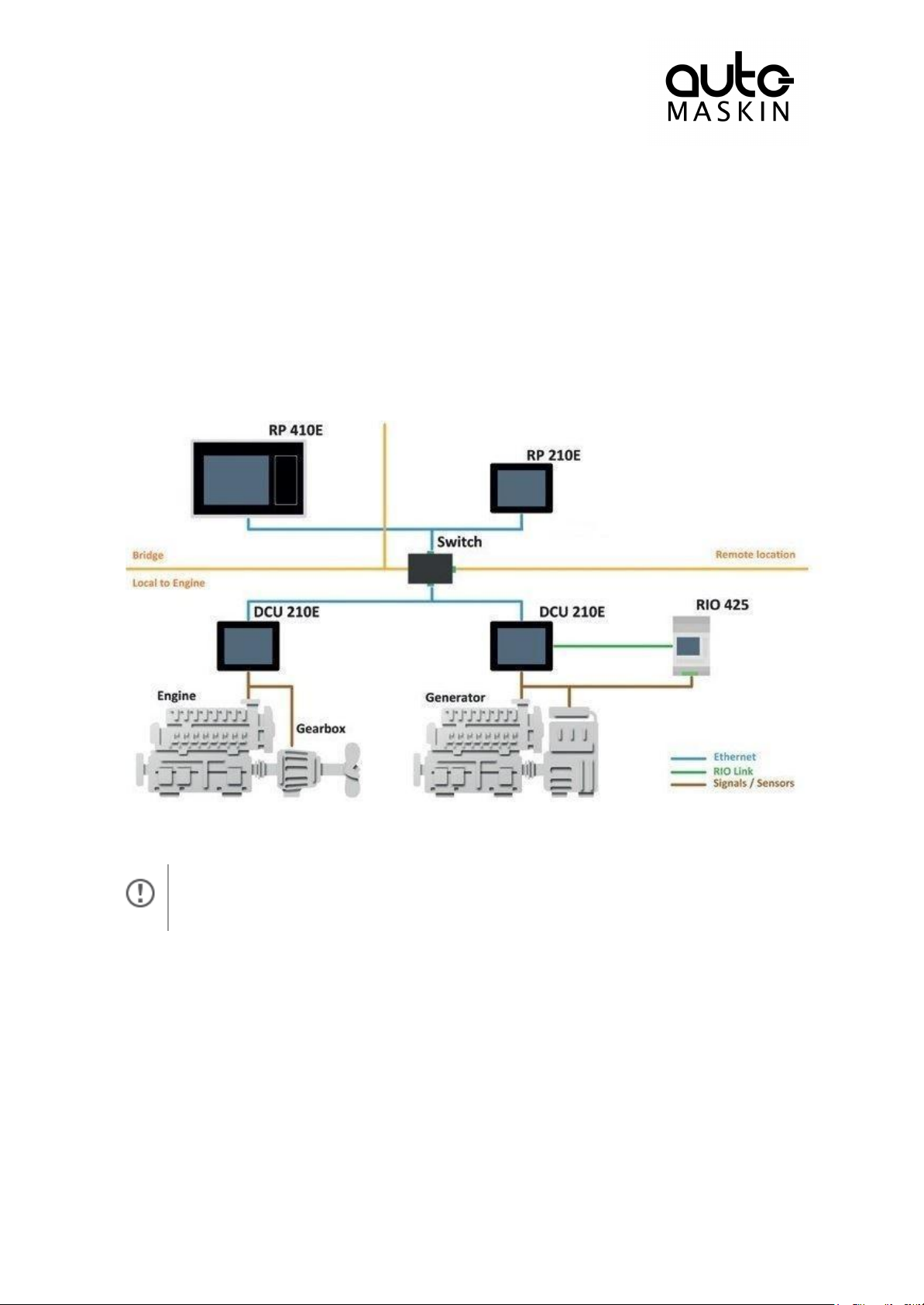
The drawing below shows a typical layout.
3.1 DCU 210E Engine Controller
The DCU 210E Engine Controller is the main building block in the 200 Series.
Engine sensor values are displayed on the color touch screen, and commands and other
user interaction is also here.
3.2 DCU 208E Engine Controller
The DCU 208E is basically the same as the DCU 210E, but without the color touch screen.
It saves cost being used in smaller engine rooms, where a remote panel is all that is needed.
Page 5
3.3 RP 210E/220E Remote Panel
At the first Power-Up the user will be guided through a Setup Wizard
1. Language selection and your choice is valid through the rest of the
procedure.
Page 5 (20)
The optional RP Remote Panels brings everything on the DCU to a remote location, with the
exact same user interface. It does not need any configuration, as it is reading the
configuration from the DCU.
As such, the RP can easily be retrofitted.
The RP also supports one IP-camera to be installed on the network.
3.4 Ethernet Switch
The Ethernet switch is not necessary if only one DCU 210E and one RP 210E is in use.
These can then be wired with an Ethernet cable directly.
It is recommended to make use of an Ethernet switch though, as it simplifies PC
configuration connection and future expansion to remote panels and/or camera interface.
3.5 Expansion
The basic system can be expanded with more input and output channels using the versatile
RIO units (Remote I/O).
Currently, there are RIO units for
● General I/O expansion, RIO 410 and RIO 210.
● Exhaust temperature monitoring, RIO 412
● Generator monitoring, RIO 425
● Load sharing, LSU 408
4 DCU 210E Engine Controller
4.1 First Power On
Use a Web-browser to set up and configure the DCU.
PC Connection/Setup:
● Connect via Ethernet using a net browser
● From the Address Field in the Browser, type the IP-Address. Factory Default is
192.168.0.101.
● Then log in to the unit. Factory Default Username is ‘DCU’ and Factory Default
password is ‘1234’.
For further details and information, please see the Configuration Manual.
Page 6
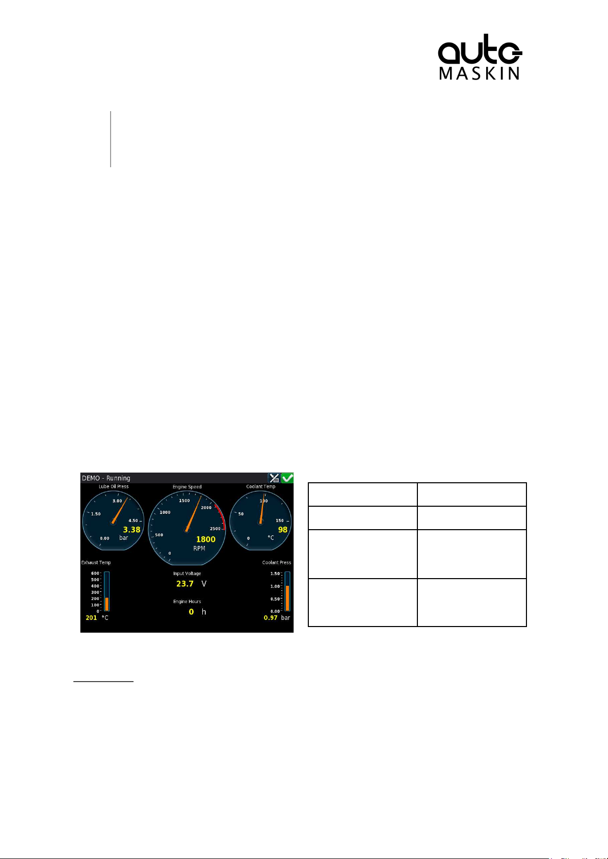
2. Network settings. Make sure to follow common network configuration
practice and take care when several units need to operate within the same
network.
4.2 Configuration Dependency
To do this
Press this
Select page
Center of the screen
Previous screen
Left-hand side
(midway) of the
screen
Next screen
Right-hand side
(midway) of the
screen
Page 6 (20)
The behavior of the panel depends somewhat on its configuration.
For instance, the start/stop buttons can be configured either as latched, meaning the DCU
completes the start/stop cycle once the button is pressed, or hold-to, meaning the operator
must keep the button pressed until the engine has started or stopped.
The configuration of the DCU is not part of this document.
4.3 Main Elements of the Touch Screen
The DCU 210E (not the DCU 208E) uses a touch screen for all user interaction.
The DCU 208E does not have a user interface; please see the RP 210E Remote Panel
section.
4.3.1 Screen Navigation and Hot-spots
The screen has a few hot-spot areas predefined for certain functions.
For instance, pressing the left-hand side of the screen moves to the previous page (if any).
Screen animations will aid the user in understanding the different hot-spot actions.
Select Page
Press the center of the screen to get a miniature (thumbnail) of all the instrument pages for
easy access.
This is the quickest and easiest way to get an overview and select what page to navigate to.
Page 7
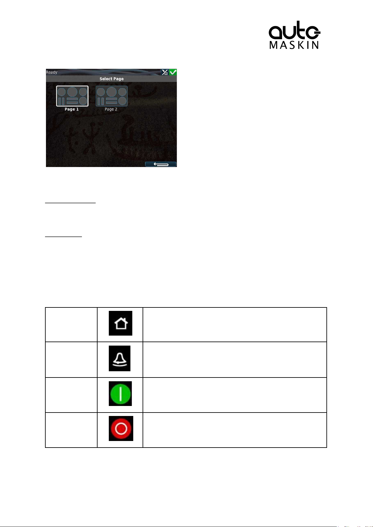
In the above example, there are two instrument pages available.
Home
The Home button located at the upper right corner always
displays the first page of instruments.
Alarm List
The Alarm List button located at the right side of the panel
shows the alarm list. Press the button again to leave the alarm
list.
Start Engine
The Start button located on the right side of the panel can be
configured as latched or hold. See Start Engine Section for
further details.
Stop Engine
The Stop button located at the bottom right side can be
configured as latched or hold. See Stop Engine Section for
further details.
Page 7 (20)
Select one of the two thumbnail pages to move directly to that page.
Previous Screen
From the instrument view, press the left-hand side of the screen to move to the previous
screen.
Next screen
From the instrument view, press the right-hand side of the screen to move to the next
screen.
4.4 Panel Buttons
The DCU has four buttons for quick access to main functions.
Page 8
4.5 Screen Layout
DCU is in automatic mode.
DCU is in manual mode.
DCU is in local mode.
DCU is in harbor mode.
DCU is in emergency mode.
DCU is in shutdown override mode.
A service interval is past due.
All OK.
(no alarms)
Gear in Neutral position.
Gear in Forward position.
Gear in Reverse position.
Gear Engaged.
(direction unknown)
Gear status Unknown.
Page 8 (20)
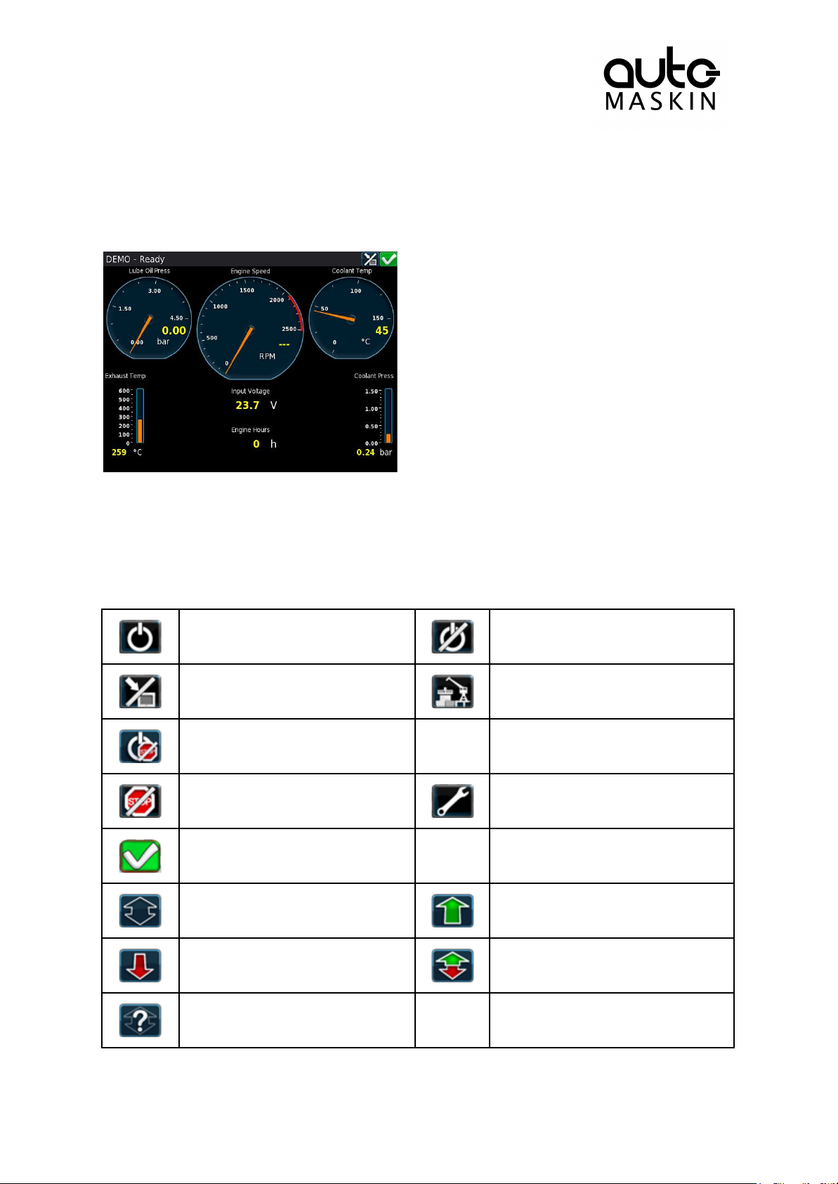
At the top area of the screen is the Status Bar. The left-hand side indicates the Engine
Status and the right-hand side is dedicated for Panel Status.
4.5.1 Status Bar Symbols
The following symbols may appear in the status bar and several symbols may be visible
simultaneously.
Page 9
Automatic Mode
Page 9 (20)
The DCU is ready to accept automatic start- and stop commands.
Local start and stop is not possible, unless allowed in configuration.
Emergency Mode
To enter this mode the DCU need to be configured as a Combined Harbor/Emergency set.
Channels configured as shutdown will not cause any engine shutdown but indicate with
alarms only.
Overspeed is an exception that can’t be disabled.
Manual Mode
In Manual Mode, the DCU does not accept external automatic start- and stop commands.
Local start and stop is not possible, unless allowed in configuration.
Harbor Mode
This mode is available only if the DCU is configured as a Combined Harbor/Emergency set.
● Shutdown channels are enabled.
● Automatic start/stop is disabled.
Shutdown Override
All channels configured as shutdown will give an alarm only.
Overspeed is an exception that can’t be disabled.
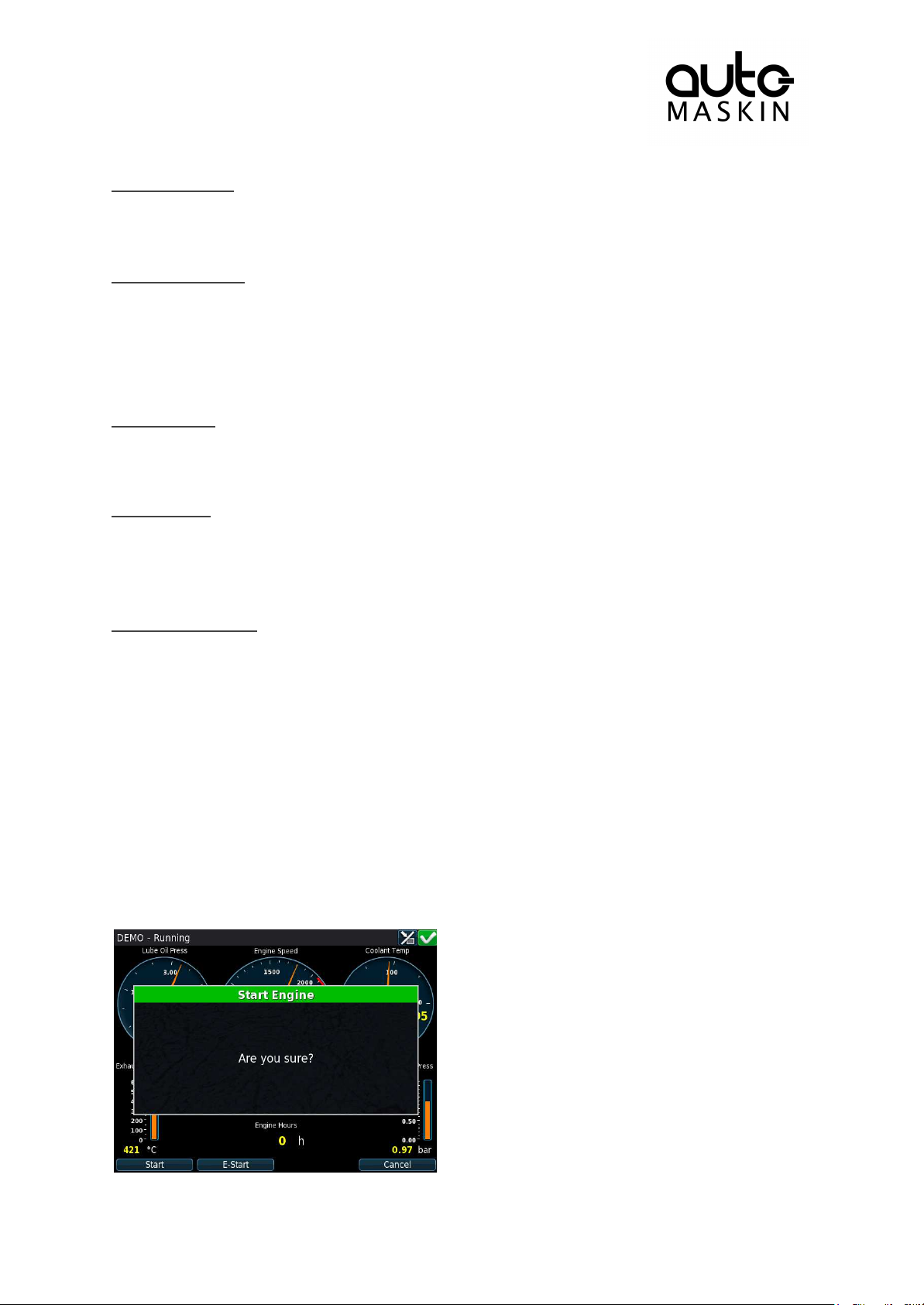
4.6 Start Engine
The start button can be configured as latched or hold-to.
4.6.1 Latched Start
If the button is configured as latched, press the start button, observe the confirmation dialog,
and press the soft-button Start to start.
The DCU will complete the start sequence.
Page 10
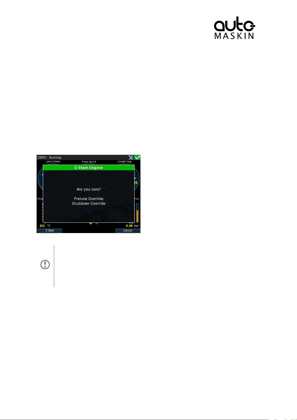
4.6.2 Hold-to Start
Activating E-Start will override any configured Prelube and also set Shutdown
Override. The engine will start immediately, and run in a Shutdown Override mode
setting.
If desired, the operator can switch off Shutdown Override mode once the engine
has started.
Page 10 (20)
If the start button is configured as hold-to, press and hold the start button until the engine
has started.
There will be no confirmation dialog.
4.6.3 E-Start
If the DCU is configured for it, an Emergency Start option is available in the Start dialog. See
the picture above.
The E-Start is designed to start the engine as quickly as possible in an emergency situation,
and shall not be used for everyday start.
4.7 Stop Engine
The stop button can be configured as latched or hold-to.
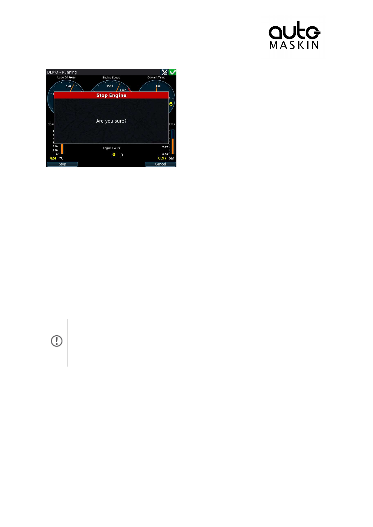
4.7.1 Latched Stop
If the button is configured as latched, press the stop button, observe the confirmation dialog,
and press the stop soft-button.
The DCU will complete the stop sequence.
Page 11
4.7.2 Hold-to Stop
The color of the flashing status bar indicates the type of event.
● Yellow: Warning
● Red: Critical Alarm or shutdown
The red bar takes precedence over yellow.
Page 11 (20)
If the stop button is configured as hold-to, press and hold the stop button until the engine
has stopped.
There will be no confirmation dialog.
4.8 Alarm List
4.8.1 Indication
Whenever there is a new event in the alarm list, the DCU indicates as follows:
● Buzzer sounds
● The screen status bar flashes yellow or red
4.8.2 Enter the Alarm List
To see the alarm list, press the alarm list button or the top-right section of the screen, as
discussed earlier.
Page 12
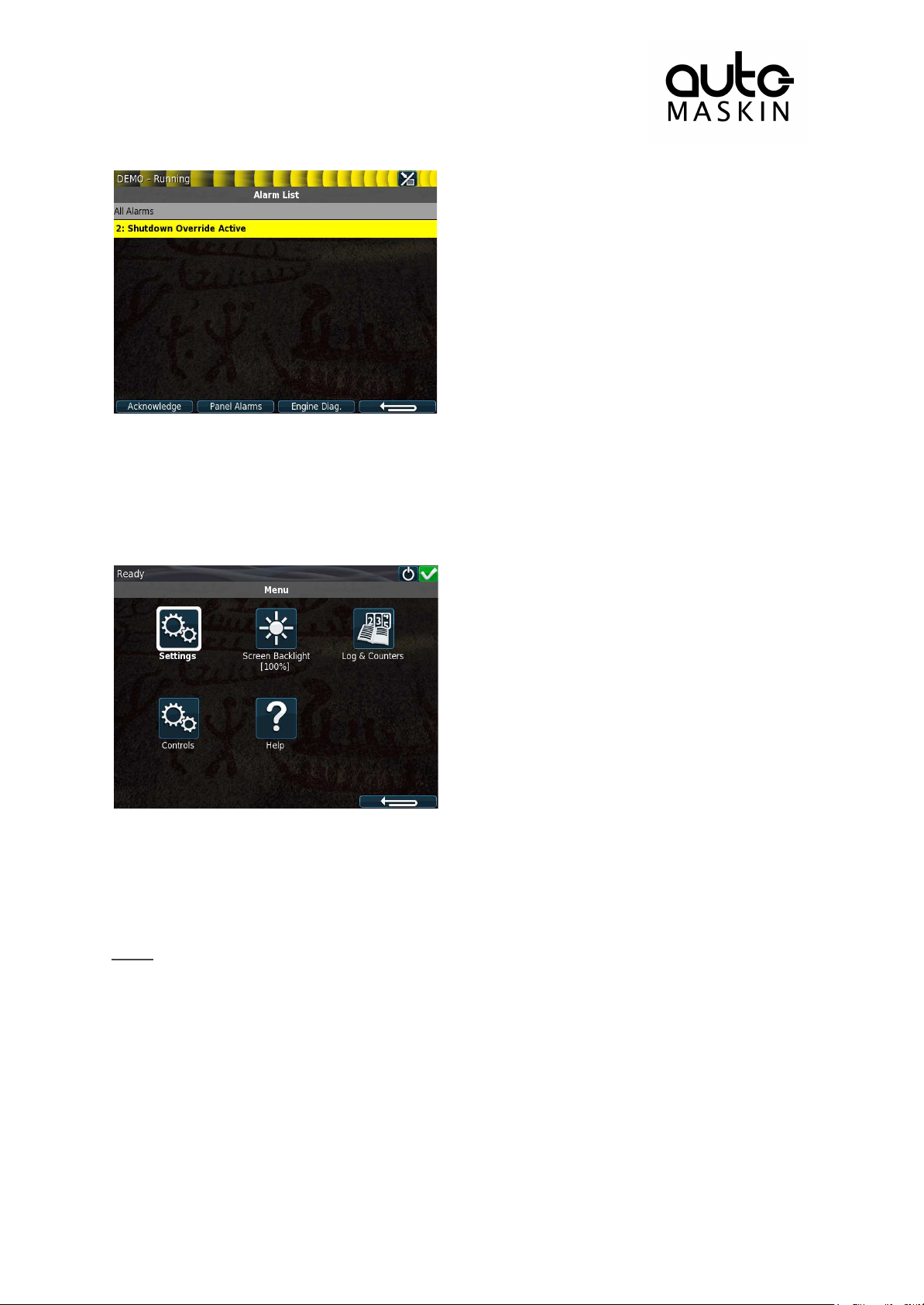
The above picture indicates a warning in the alarm list.
Page 12 (20)
For further explanation, see the chapter The Alarm List.
4.9 Menu
The menu page has five icons.
4.9.1 Settings
Access all panel settings.
There are three pages with icon selections in the submenu.
Mode
Select the operating mode.
Page 13
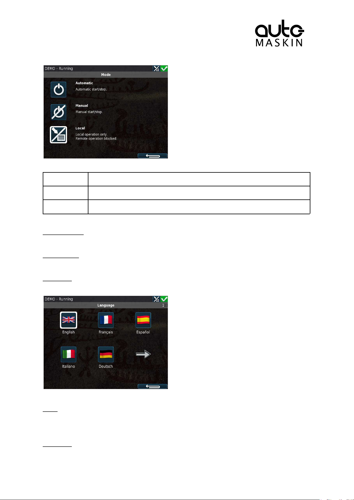
Automatic
The panel accepts signals for automatic start/stop of the engine.
Manual
The panel does not accept signals for automatic start/stop of the engine.
Local
The panel does not accept any remote commands.
Start Disabled
Page 13 (20)
Set to Active to disable start.
Button Beep
Set to Enable to have each screen press sound the buzzer.
Language
Select any of the panel’s built-in languages.
The panel configuration may not be translated to the selected language.
Units
Select Metric or U.S. units of measure.
Any gauge scaling is handled in the configuration.
Wallpaper
Page 14
Select any of the built-in wallpapers as a background for instruments, menus and popup
Page 14 (20)
dialogs.
Connect a PC
The panel has an inbuilt DHCP server, and thus can issue an IP address to a PC that is
configured to receive a dynamic IP address in a company network.
Set the Start- and End IP to be outside of the panel’s current IP address, and press OK.
Administration
This section covers deeper configuration options of the panel, and is not covered in this
manual.
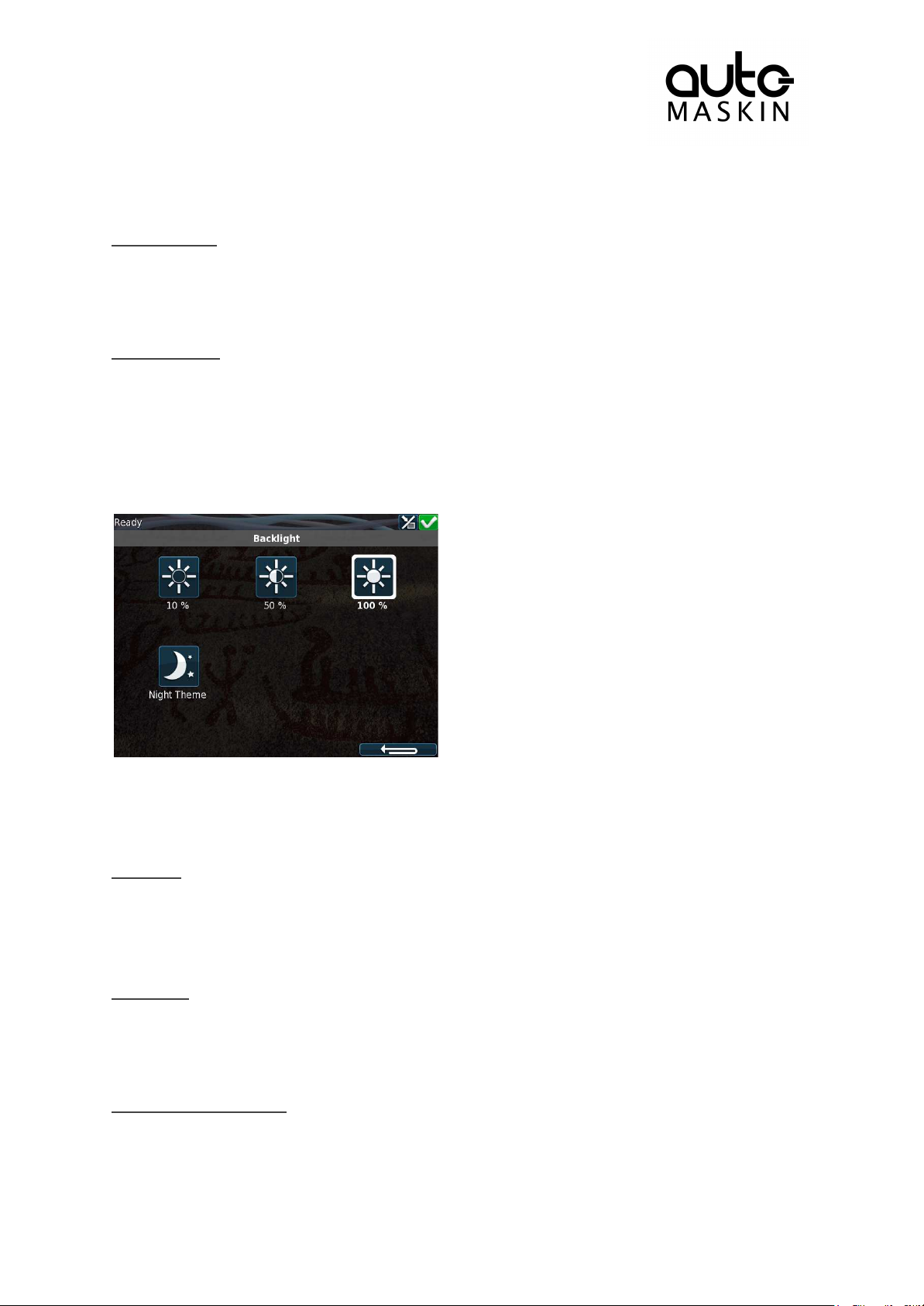
4.9.2 Screen Backlight
Adjust screen backlight intensity for varying light conditions.
4.9.3 Log & Counters
There are submenus for engine operating hours, event log and service intervals.
Counters
The submenu has the engine hours, in total, since start and since the last reset.
The Since Start value is automatically reset every time the engine makes a new start.
The Since Reset values can be reset manually using the button provided.
Event Log
All panel events are stored internally, and can be monitored here.
Select an event to see when it first appeared, when it was acknowledged (if applicable for
that event) and when it disappeared (again, if applicable).
Engine Service Interval
If engine service intervals are configured, then this page displays how many hours until the
next service.
Page 15
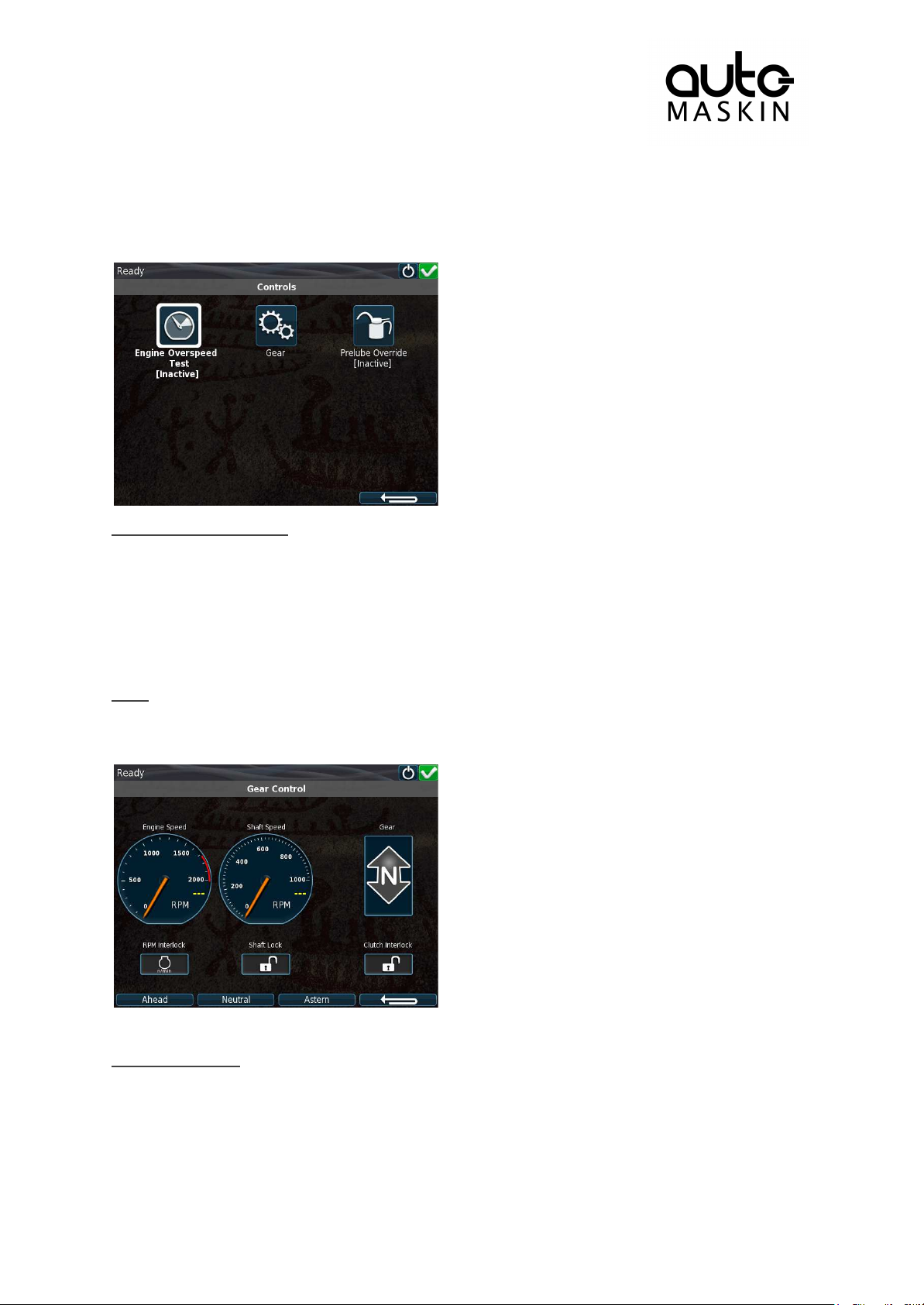
4.9.4 Controls
Page 15 (20)
Access certain engine related functions.
Engine Overspeed Test
Set to Active to activate the engine overspeed test.
This temporarily lowers the overspeed setpoint to the nominal speed of the engine. Start the
engine to perform the test.
The test will deactivate automatically after a timeout, or when an actual overspeed (from the
test) is detected.
Gear
Opens the Gear Control form. Note, this function may not be available, as it depends on how
the DCU is configured.
This form is used to inspect transmission related parameters and to request gear changes.
Prelube Override
Activates or deactivates Prelube Override. When active , a start attempt will skip the prelube
sequence and attempt to start the engine immediately. Prelube Override is automatically
deactivated after a start attempt. Note, this function is anly present if the DCU is configured
to perform prelubing prior to start of the engine.
Page 16
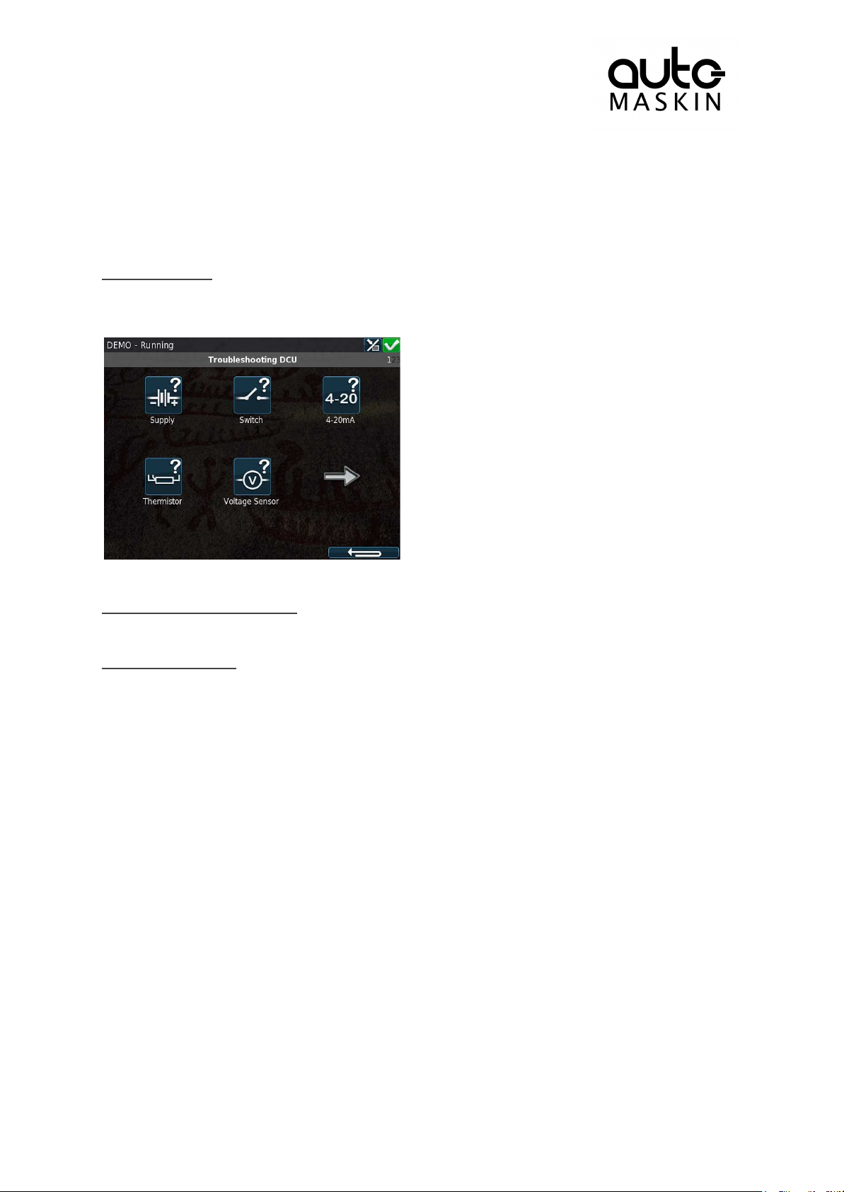
4.9.5 Help
Page 16 (20)
Submenus for troubleshooting and panel version information, such as firmware version and
IP address.
Troubleshooting
This submenu has troubleshooting information for the panel itself in addition to every RIO
expansion unit connected.
Select the icon that represents the area of interest.
Troubleshooting Diagnostics
Additional CPU related Information; Temperature, Frequency and Load.
Version Information
This page displays panel hardware version, software version, kernel version and also the
engine ECM software version (if connected to the J1939 CANbus).
Of special interest here is the panel IP address, which is necessary when connecting to the
panel using a PC.
5 RP 210E/220E/206E Remote Panel
5.1 Introduction
The RP 210E, RP 220E and RP 206E are remote panels for DCUs in the Marine Pro 200
and 400 series.
It reads the configuration from the DCU Engine Controller it is connected to. If the DCU has
a configuration change, then the RP Remote Panel will automatically adapt.
The RP 210E can monitor and control one DCU engine panel only.
The RP 220E can monitor and control two DCU engine panels.
The RP 206E can monitor two DCU engine panels. It can not control start/stop.
Page 17
5.1.1 Similarities with the DCU 210E
This RP is the active station for the connected DCU.
Operator Lock is active.
Page 17 (20)
The use of the RP 210E/220E/206E remote panel is very similar to the use of the DCU 210E
panel, so this chapter will only describe the menu sections on the RP 210E/220E/206E that
are not available on the DCU 210E.
5.2 Status Bar Symbols
In addition to the symbols already mentioned for the DCU the RP has one additional symbol
to indicate active station.
5.3 Other Symbols
The RP supports a function called “Operator Locked”. When operator lock is active, (no user
input accepted from either touch screen or buttons) this symbol is displayed on the bottom
right of the screen.
5.4 Menu
The menu is accessed in the same manner as for the DCU 210E.
Upon entering the menu, the previously used menu item is pre-selected.
Page 18
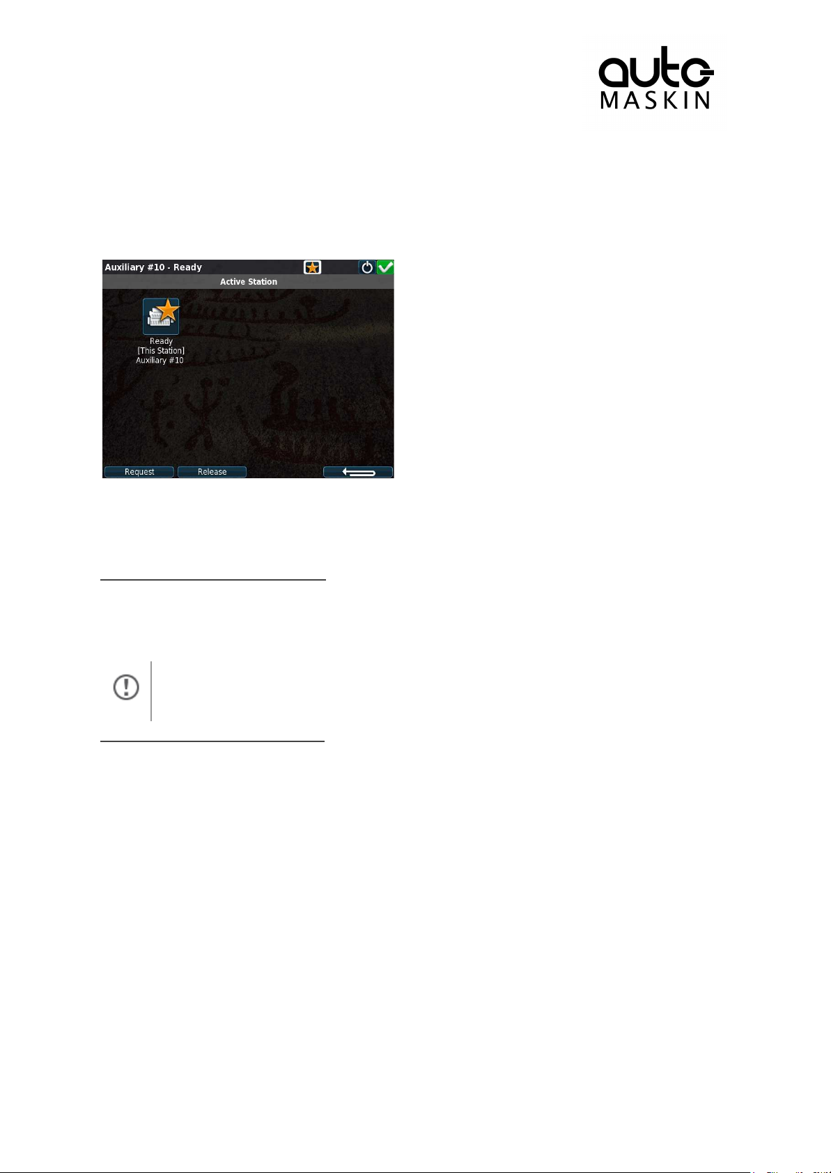
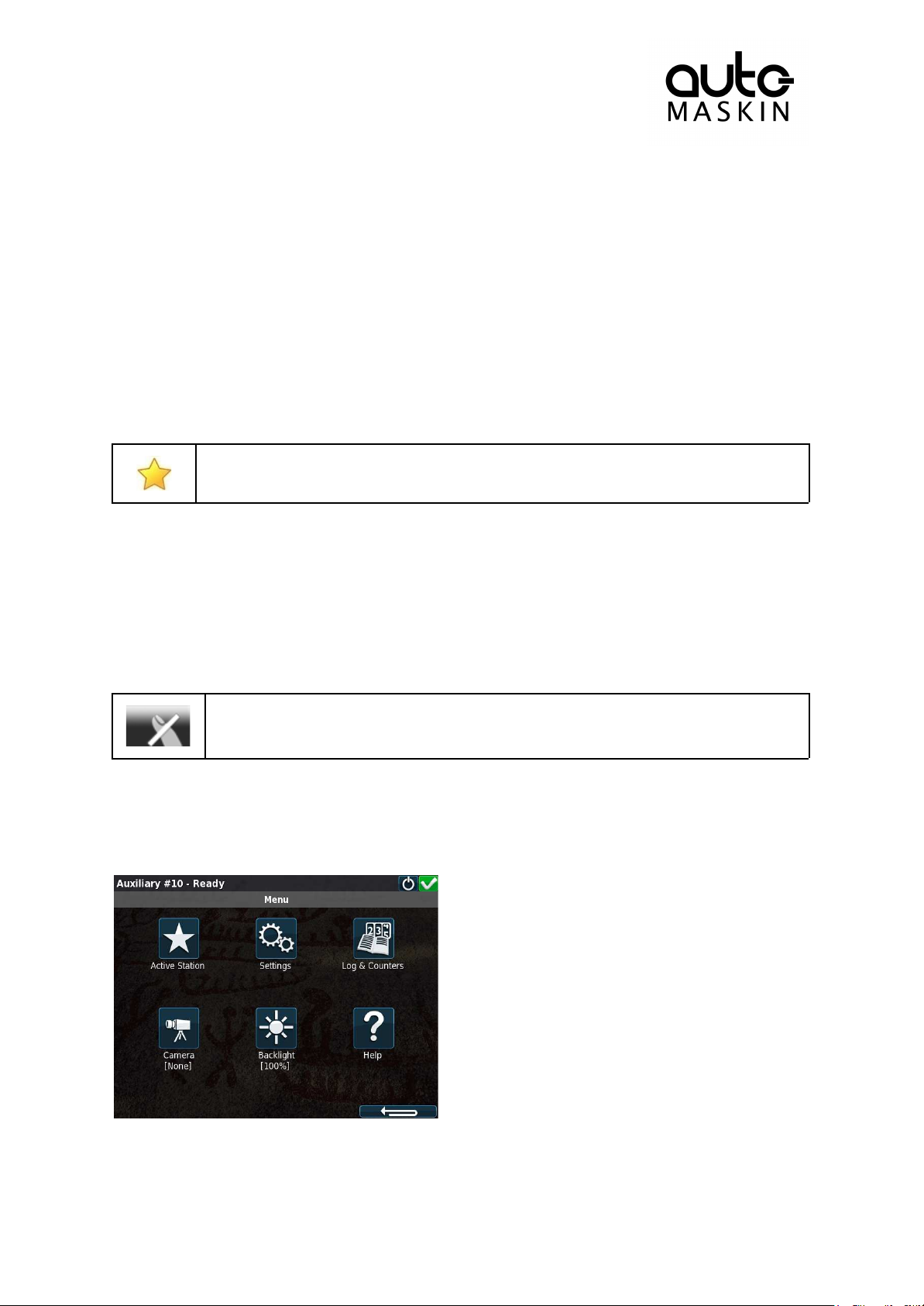
5.4.1 Active Station
If there is only one RP in the network, it may initially not be the active station.
Select it once to store current selection (this will be valid also after reboot).
Page 18 (20)
There may be several RP panels in the network, all controlling the same engine.
Only one remote panel can be in control of the engine at any given time.
The Active Station dialog displays the connected engine this RP.
If there is a yellow star in the top-right position of the icon, as in the picture above, then this
RP is currently in control of that engine.
Request the Active Station status
If the RP is not the active station for the engine, send a request to the RP with the current
active station status.
Select the engine and then select Request.
Release the Active Station status
The RP can release its Active Station status and make the engine “free” or available on the
network.
Other RP panels with lower priority settings than this RP can now become the active station
for that engine.
Select the engine, and then press the Release button.
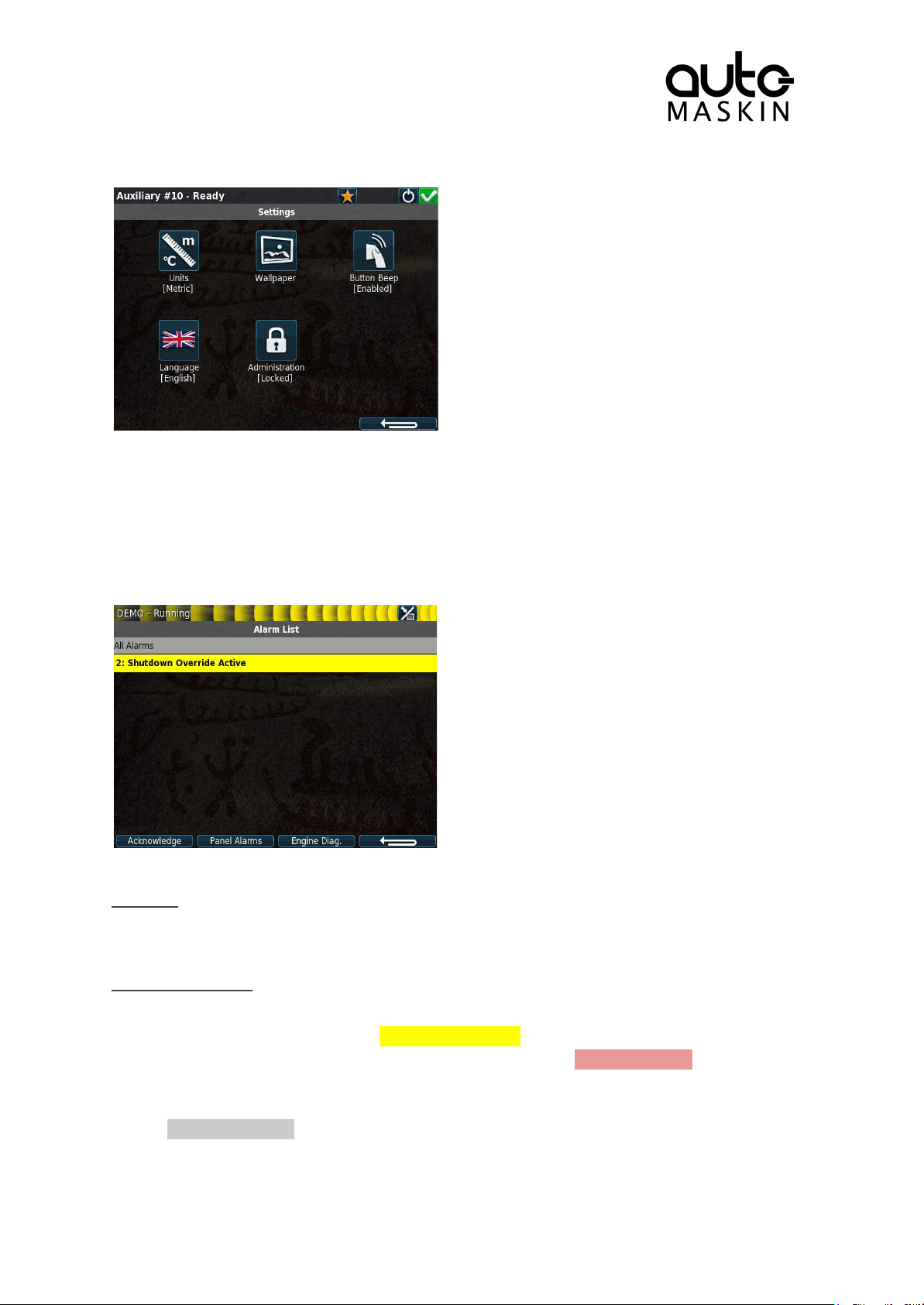
5.4.2 Settings
This chapter describes the menu icons that are not found on the DCU 210E only.
Page 19
5.4.3 Camera
Page 19 (20)
The RP panel can display images from a connected IP-camera.
6 The Alarm List
The following is valid for the alarm list in the DCU and RP panels.
Bold text
● An unacknowledged event is in bold text.
● An acknowledged event is in normal text.
Background colors
● A diagnostic message is displayed on a white background.
● A warning is displayed on a yellow background.
● An alarm and an engine shutdown are displayed on a red background. In addition, an
engine shutdown is indicated with a STOP sign.
● An unacknowledged event that turned inactive before acknowledge, is displayed on a
grey background. For instance, the coolant temperature may have been above the
setpoint, and then dropped below the setpoint again before the operator
acknowledged it.
Page 20

Active Alarms will stay displayed until they go inactive.
6.1 Filter Alarms
Page 20 (20)
The alarm list can filter alarms in three groups as follows
● All Alarms (alarms and diagnostics)
● Panel Alarms (alarms, no diagnostics)
● Diagnostics (diagnostics only)
Press the corresponding button at the bottom of the screen for the desired filter to take
effect.
The filter currently in use is displayed on the second line of the alarm list, e.g. All Alarms.
6.2 Silence the Buzzer
Entering the alarm list will also automatically silence the buzzer.
If the buzzer sounds while in the alarm list, then press the Ack. Alarms button to silence it.
6.3 Acknowledge a Single Alarm
● In the alarm list, select the alarm to be acknowledged. Observe that the selected
alarm line will expand to reveal additional information, if any.
● Press the Ack. Alarms button to acknowledge the selected alarm.
6.4 Acknowledge All Alarms
● In the alarm list, press and hold (1 sec) the Ack. Alarms button. This acknowledges
all active alarms.
 Loading...