

Page 1

RSUK0287_POH_Cavalon Revision 2, Issue Date 24.06.2015 Pre-pages 1
RotorSport UK Ltd
Poplar Farm
Prolley Moor
Wentnor
Bishops Castle
SY9 5EJ
Company Reg No 5486550
Phone: +44 (0) 1588 650769
Fax: +44 (0) 1588 650769
Email: [email protected]
Approval number DAI/9917/06
Pilot’s Operating Handbook
for Gyroplane Cavalon
Page 2

RSUK0287_POH_Cavalon Revision 2, Issue Date 24.06.2015 Pre-pages 2
Flight and Operation Manual for Gyroplane
Cavalon
Model: Cavalon _________________________________________
Serial number: RSUK/CVLN/_____________________________________
Registration: G-???? _________________________________________
Engine: 914UL or 912ULS serial ____________________________
Propeller: HTC 1,73m ground adjustable propeller ________________
or
IVO-prop DL3-68 in-flight variable pitch propeller_________
Rotor: Autogyro 8.4m RotorSystem II RAO (red end caps, black
spacers (clamp profiles)) or RotorSystem II TOPP (blue
end caps, silver spacers (clamp profiles))_______________
Aircraft manufacturer and
type approval holder: RotorSport UK Ltd
Prolley Moor,
Wentnor,
Bishops Castle,
Shropshire,
SY9 5EJ
Owner: _______________________________________________
_______________________________________________
_______________________________________________
This flight manual is always to be carried on board of the aircraft and must be kept in
current, up-to-date status. The latest revisions and version status is available at
www.rotorsport.org. Extent and revision status of the manual is recorded in the revision log
and the table of contents.
This gyroplane may be operated only in strict compliance with the limitations and
procedures contained in this manual.
The manual is not a substitute for competent theoretical and practical training on the
operation of this aircraft. Failure to adhere to its provisions or to take proper flight
instruction can have fatal consequences.
Page 3

RSUK0287_POH_Cavalon Revision 2, Issue Date 24.06.2015 Pre-pages 3
REVISION LOG
Rev. Change summary Date Signature
1.0 First formal release 12.04.13
2.0 560kg MTOW (MC-281) and
IVO-prop (MC-276) recognised.
All pages republished at Rev 2.
24.06.15
3.0 TOPP Rotor option added P1-4
para 1.9, P7-5 para 7.8, Caution
para 8.15.1
Vertical CG limit increased to
940, page 2-7 para 2.7.2.
06.04.16
Pilots Flight and Operation Manual Document approval
Page 4

RSUK0287_POH_Cavalon Revision 2, Issue Date 24.06.2015 Pre-pages 4
Signature:
Position:
Chief Test Pilot
Signature:
Position:
Engineering Manager
Signature:
Position: Head of
Airworthiness
Page 5

Flight Manual
Cavalon
Table of Contents
List of Effective Pages
RSUK0287_POH_Cavalon Revision 2, Issue Date 24.06.2015 Index / LOEP 1
CONTENTS
GENERAL................................................................................................... 1-1
SECTION 1 -
1.1 Introduction.................................................................................................... 1-1
1.2 Certification ................................................................................................... 1-1
1.3 Performance Data and Operating Procedures ............................................... 1-1
1.4 Definition of Terms ........................................................................................ 1-3
1.5 Important Note............................................................................................... 1-3
1.6 Three-view of the Cavalon.............................................................................1-4
1.7 Description .................................................................................................... 1-5
1.8 Technical Data ..............................................................................................1-5
1.9 Rotor ............................................................................................................. 1-5
1.10 Engine........................................................................................................... 1-6
1.11 Propeller........................................................................................................ 1-6
1.12 Unit Conversion............................................................................................. 1-7
1.13 Abbreviations and Terminology ..................................................................... 1-8
LIMITATIONS .............................................................................................2-1
SECTION 2 -
2.1 General .........................................................................................................2-1
2.2 Environmental Limitations.............................................................................. 2-3
2.3 Colour Code for Instrument Markings ............................................................ 2-3
2.4 Airspeed Limitations and Instrument Markings...............................................2-4
2.5 Rotor Speed Limitations and Instrument Markings.........................................2-4
2.6 Powerplant Limitations and Instrument Markings........................................... 2-5
2.7 Weight and Balance ......................................................................................2-7
2.8 Flight Crew .................................................................................................... 2-8
2.9 Kinds of Operation.........................................................................................2-8
2.10 Fuel ............................................................................................................... 2-9
2.11 Minimum Equipment......................................................................................2-9
2.12 Placards ...................................................................................................... 2-10
EMERGENCY PROCEDURES...................................................................3-1
SECTION 3 -
3.1 Engine Failure ............................................................................................... 3-1
3.2 Air Restart Procedure .................................................................................... 3-2
3.3 Landing into Trees or High Vegetation........................................................... 3-2
3.4 Degradation of Engine Power ........................................................................ 3-2
3.5 Evacuating the Aircraft................................................................................... 3-3
3.6 Smoke and Fire ............................................................................................. 3-3
3.7 Off-field Landing ............................................................................................ 3-3
3.8 Flight Control Malfunction..............................................................................3-4
3.9 Pitch oscillation recovery ............................................................................... 3-5
3.10 Vibration........................................................................................................ 3-5
3.11 Door open in flight. ........................................................................................ 3-7
3.12 Warning and Caution Lights........................................................................... 3-8
3.13 Parameters out of Limits..............................................................................3-10
Page 6

Flight Manual
Cavalon
Table of Contents
List of Effective Pages
RSUK0287_POH_Cavalon Revision 2, Issue Date 24.06.2015 Index / LOEP 2
3.14 Rotor Bearing Temperature......................................................................... 3-10
3.15 Loss of Visibility........................................................................................... 3-11
3.16 (not used).................................................................................................... 3-11
3.17 Rotor Icing................................................................................................... 3-11
3.18 Landing with a Deflated Tyre....................................................................... 3-11
3.19 Not used ..................................................................................................... 3-12
3.20 Alternative Method of Engine Shut-down..................................................... 3-12
NORMAL PROCEDURES .......................................................................... 4-1
SECTION 4 -
4.1 Airspeeds for Safe Operation ........................................................................ 4-1
4.2 Preparation for Flight..................................................................................... 4-1
4.3 Daily or Pre-flight Checks.............................................................................. 4-1
4.4 Before Boarding ............................................................................................ 4-4
4.5 Before Starting Engine .................................................................................. 4-5
4.6 Starting Engine.............................................................................................. 4-6
4.7 Taxi and Run-up............................................................................................ 4-7
4.8 Take-off Procedure ....................................................................................... 4-7
4.9 Take-off Run ................................................................................................. 4-9
4.10 Climb............................................................................................................. 4-9
4.11 Cruise ........................................................................................................... 4-9
4.12 Descent......................................................................................................... 4-9
4.13 Approach..................................................................................................... 4-10
4.14 Landing ....................................................................................................... 4-10
4.15 Go-around................................................................................................... 4-11
4.16 After Landing............................................................................................... 4-11
4.17 Engine Shut-down....................................................................................... 4-12
4.18 Parking........................................................................................................ 4-12
4.19 Special Procedure: Short Field Take-off ...................................................... 4-12
4.20 Special Procedure: Slow Speed Sink and Recovery.................................... 4-12
4.21 Flight with Doors Removed ......................................................................... 4-13
4.22 Training Engine In-flight Shut-down and Air Restart .................................... 4-14
4.23 Noise Abatement......................................................................................... 4-14
PERFORMANCE........................................................................................ 5-1
SECTION 5 -
5.1 Demonstrated Operating Temperature .......................................................... 5-1
5.2 Airspeed Correction....................................................................................... 5-1
5.3 Height-Velocity Diagram................................................................................ 5-2
5.4 Speeds.......................................................................................................... 5-3
5.5 Rate of Climb ................................................................................................ 5-3
5.6 Take-off and Landing Data............................................................................ 5-3
5.7 Influence on Take-off Distance and Climb Rate............................................. 5-4
5.8 Sink Rate and Glide Ratio ............................................................................. 5-6
5.9 Additional Performance Data......................................................................... 5-6
5.10 Sound Exposure Level / Noise Characteristics .............................................. 5-6
WEIGHT AND BALANCE ........................................................................... 6-1
SECTION 6 -
6.1 General ......................................................................................................... 6-1
Page 7

Flight Manual
Cavalon
Table of Contents
List of Effective Pages
RSUK0287_POH_Cavalon Revision 2, Issue Date 24.06.2015 Index / LOEP 3
6.2 Weight and Balance Record..........................................................................6-1
6.3 Compliance with Weight and Balance............................................................ 6-1
SYSTEM DESCRIPTION............................................................................ 7-1
SECTION 7 -
7.1 Introduction.................................................................................................... 7-1
7.2 Airframe and Undercarriage........................................................................... 7-1
7.3 Doors, Windows and Exits.............................................................................7-1
7.4 Fuel System .................................................................................................. 7-1
7.5 Pneumatic System.........................................................................................7-3
7.6 Power Plant................................................................................................... 7-4
7.7 Propeller........................................................................................................ 7-4
7.8 Rotor System.................................................................................................7-4
7.9 Vibration Damping......................................................................................... 7-5
7.10 Flight Controls ............................................................................................... 7-5
7.11 Electrical System........................................................................................... 7-8
7.12 Lighting System............................................................................................. 7-9
7.13 Electrical circuit protection.............................................................................7-9
7.14 Avionics....................................................................................................... 7-11
7.15 Instrument Panel ......................................................................................... 7-12
7.16 Intercom ...................................................................................................... 7-14
7.17 Pitot Static ................................................................................................... 7-14
7.18 Indicators and Sensors................................................................................ 7-14
7.19 Seats and Seatbelts .................................................................................... 7-14
7.20 Stowage Capacity........................................................................................ 7-14
HANDLING AND SERVICING..................................................................... 8-1
SECTION 8 -
8.1 Maintenance Obligations ............................................................................... 8-1
8.2 General .........................................................................................................8-1
8.3 Ground Handling ........................................................................................... 8-2
8.4 Cleaning........................................................................................................ 8-2
8.5 Refuelling ...................................................................................................... 8-3
8.6 Checking of Engine Oil Level......................................................................... 8-3
8.7 Checking of Engine Coolant Level................................................................. 8-4
8.8 Tyre Pressure................................................................................................ 8-4
8.9 Lubrication and Greasing............................................................................... 8-5
8.10 Replenishing of Fluids ...................................................................................8-5
8.11 Engine Air Filter............................................................................................. 8-5
8.12 Propeller........................................................................................................ 8-5
8.13 Battery........................................................................................................... 8-6
8.14 Winter Operation ........................................................................................... 8-6
8.15 Removal, Disassembly, Assembly and Installation of the Rotor..................... 8-6
8.16 Road Transport ........................................................................................... 8-10
8.17 Repairs........................................................................................................ 8-10
SUPPLEMENTS .......................................................................................... 9-i
SECTION 9 -
9-1 IVO-prop in-flight adjustable variable pitch propeller. ..................................................... 1
9-2 Lights............................................................................................................................. 1
Page 8

Flight Manual
Cavalon
Table of Contents
List of Effective Pages
RSUK0287_POH_Cavalon Revision 2, Issue Date 24.06.2015 Index / LOEP 4
9-2.1 General ............................................................................................................ 1
9-2.2 Limitations........................................................................................................ 1
9-2.3 Emergency Procedures.................................................................................... 1
9-2.4 Normal Procedures .......................................................................................... 1
9-2.5 Performance .................................................................................................... 1
9-2.6 Weight and Balance ......................................................................................... 1
9-2.7 System Description .......................................................................................... 1
9-2.8 Handling and Servicing .................................................................................... 1
9-3 GPS/Moving Map Systems............................................................................................ 1
9-3.1 General ............................................................................................................ 1
9-3.2 through 9-3.6 ......................................................................................................... 1
9-3.7 System Description .......................................................................................... 1
9-3.8 Handling and Servicing .................................................................................... 1
9-4 Fire Indication................................................................................................................ 1
9-4.1 General ............................................................................................................ 1
9-4.2 Limitations........................................................................................................ 1
9-4.3 Emergency Procedures.................................................................................... 1
9-4.4 through 9-4.9 ......................................................................................................... 1
9-5 Not used........................................................................................................................ 1
9-6 Not used........................................................................................................................ 1
SAFETY TIPS......................................................................................... 10-1
SECTION 10 -
Low-G Avoidance ...................................................................................................... 10-1
Side Slip in Gyroplanes.............................................................................................. 10-1
Flying Low on Fuel Is Dangerous............................................................................... 10-2
Do Not Push the Envelope and Remain Easy On the Controls .................................. 10-2
Strobe Lights On – For Your Own and Other’s Safety................................................ 10-2
Propellers and Rotors Can Be Extremely Dangerous................................................. 10-2
Power Lines and Cables Are Deadly.......................................................................... 10-2
Loss of Visibility Can Be Fatal.................................................................................... 10-2
Overconfidence Prevails in Accidents ........................................................................ 10-3
Flying Low over Water is Very Hazardous ................................................................. 10-3
Conversion Pilots Constitute High Risk When Flying Gyroplanes............................... 10-3
Beware of Demonstration or Initial Training Flights .................................................... 10-4
Training Off-Field Simulated Engine Failures............................................................. 10-4
APPENDIX ..................................................................................................................... 10-1
Operator Registration Form
Incident Reporting Form
Page 9
Flight Manual
Cavalon
Table of Contents
List of Effective Pages
RSUK0287_POH_Cavalon Revision 2, Issue Date 24.06.2015 Index / LOEP 5
LIST OF EFFECTIVE PAGES
Page(s)
Rev.
Date
Page(s)
Rev.
Date
1-1 to 1-8 3 06.04.16 9-1 - 1 to 3 2 24.06.15
2-1 to 2-10 3 06.04.16 9-2 - 1 2 24.06.15
3-1 to 3-9 2 24.06.15 9-3 - 1 2 24.06.15
4-1 to 4-13 2 24.06.15 9-4 - 1 2 24.06.15
5-1 to 5-6 2 24.06.15 9-5 - 1 to 2 2 24.06.15
6-1 2 24.06.15 9-6 - 1 2 24.06.15
7-1 to 7-12 3 06.04.16 10-1 to 10-4 2 24.06.15
8-1 to 8-9 3 06.04.16 Appendices 2 24.06.15
Page 10

Flight Manual
Cavalon
Table of Contents
List of Effective Pages
RSUK0287_POH_Cavalon Revision 2, Issue Date 24.06.2015 Index / LOEP 6
INTENTIONALLY LEFT BLANK
Page 11

Flight Manual
Cavalon
SECTION
1
GENERAL
RSUK0287_POH_Cavalon Revision 3.0, Issue Date 06.04.16 1 - i
CONTENTS
1.1 Introduction.................................................................................................... 1-1
1.2 Certification ................................................................................................... 1-1
1.3 Performance Data and Operating Procedures ............................................... 1-1
1.4 Definition of Terms ........................................................................................ 1-3
1.5 Important Note............................................................................................... 1-3
1.6 Three-view of the Cavalon.............................................................................1-4
1.7 Description .................................................................................................... 1-5
1.8 Technical Data ..............................................................................................1-5
1.9 Rotor ............................................................................................................. 1-5
1.10 Engine........................................................................................................... 1-6
1.11 Propeller........................................................................................................ 1-6
1.12 In-flight adjustment………………………………………………......................... 1-7
1.13 Abbreviations and Terminology ..................................................................... 1-8
Page 12

Flight Manual
Cavalon
SECTION
1
GENERAL
RSUK0287_POH_Cavalon Revision 3.0, Issue Date 06.04.16 1 - ii
INTENTIONALLY LEFT BLANK
Page 13

Flight Manual
Cavalon
SECTION
1
GENERAL
RSUK0287_POH_Cavalon Revision 3.0, Issue Date 06.04.16 1-1
GENERAL
SECTION 1 -
1.1 Introduction
This manual is designed as an operating guide for pilots, instructors, and owners/operators,
providing information for the safe and efficient operation of this gyroplane. It includes
material required to be furnished to the pilot by the competent certification authority. This
handbook is not designed as a substitute for adequate and competent flight instruction,
however.
Pilots of this aircraft must hold a proper license including the class rating ‘gyroplane’,
corresponding to the aircraft’s registration. A special endorsement may be required to fly
with passengers. It is the pilot’s responsibility to be familiar with this handbook, the special
characteristics of this gyroplane, and all other information and legal requirements relevant
for the operation in his country. The pilot is responsible to determine the gyroplane is safe
for flight, and to operate the aircraft with respect to the procedures and limitations provided
in this manual.
It is the owner’s/operator’s responsibility to have this gyroplane registered and insured,
according to country-specific regulations. The aircraft owner/operator is also responsible for
maintaining the gyroplane in airworthy condition. Maintenance instructions are provided in
the Maintenance Manual and in SECTION 8 of this manual. Note that depending on the
kind of operation, type of maintenance activity, or component involved, the competent
authority may dictate qualified personnel and/or respective facilities.
1.2 Certification
The Cavalon is designed, tested and approved according to the German design
specifications for microlight gyroplanes (“Bauvorschriften für Ultraleichte Tragschrauber”,
BUT 2001) including its latest amendment published in “Nachrichten für Luftfahrer” NfL II
13/09 issued 12.02.2009, as well as the British Civil Airworthiness Requirements (BCAR)
Section T issue 4.
The corresponding certification documents (Geräte-Kennblatt) have been issued by the
responsible Germany department DULV (Deutscher Ultraleichtflugverband e.V.),
respectively the German national certifying authority.
AUTHORITY FOR FLIGHT WITHIN THE UK
The legal basis for the operation of this CAVALON autogyro is regulated in the
Airworthiness Approval Notification (AAN29345), issued by the UK Civil Aviation Authority
(CAA). It has been shown to comply with the requirements of BCAR Section T issue 4, and
is considered as a factory built aircraft. Reference must be made the Permit to Fly
limitations issued by the CAA for each individual aircraft.
The noise certificate was granted according to the German requirements for noise
protection for microlight gyroplanes (“Lärmschutzverordnung für Ultraleichte
Tragschrauber”).
1.3 Performance Data and Operating Procedures
The legal basis for operating a gyroplane is provided by national law and its respective
regulations. The instructions and conditions contained have to be considered when
operating the gyroplane.
Page 14

Flight Manual
Cavalon
SECTION
1
GENERAL
RSUK0287_POH_Cavalon Revision 3.0, Issue Date 06.04.16 1-2
All documented performance data and operating procedures have been identified within the
approval processes for this gyroplane by means of flight test and analysis.
Page 15

Flight Manual
Cavalon
SECTION
1
GENERAL
RSUK0287_POH_Cavalon Revision 3.0, Issue Date 06.04.16 1-3
1.4 Definition of Terms
This manual uses WARNINGs, CAUTIONs and NOTEs in bold capital letters to indicate
especially critical and important instructions. Additionally, the colour of the panel (red,
yellow, and grey shading) highlights the significance of the instruction. Definitions for each
term are given below.
WARNING
A warning means that the neglect of the appropriate procedure or condition
could result in personal injury or loss of life.
CAUTION
A caution means that the neglect of the appropriate procedure or condition
could result in damage to or destruction of equipment.
NOTE
A note stresses the attention for a special circumstance, which is essential to
emphasize.
1.5 Important Note
Before each flight pilots must make themselves familiar with the appropriate navigational,
weather and safety information pertinent to their planned route.
The limitations provided in SECTION 2 of this manual must be respected at all times. Check
the manufacturer’s web site www.rotorsport.org regularly for flight manual updates,
airworthiness directives, service bulletins, or safety information.
Abrupt manoeuvres or flight in heavy turbulence must be avoided as this could lead to rotor
speed variations associated with high stress, possible damage to the aircraft, or
uncontrollable attitudes.
Page 16

Flight Manual
Cavalon
SECTION
1
GENERAL
RSUK0287_POH_Cavalon Revision 3.0, Issue Date 06.04.16 1-4
1.6 Three-view of the Cavalon
Page 17

Flight Manual
Cavalon
SECTION
1
GENERAL
RSUK0287_POH_Cavalon Revision 3.0, Issue Date 06.04.16 1-5
1.7 Description
General Characteristics
Gyroplane with nose gear wheel chassis
Aircraft structure is a GRP/CRP monocoque
Two-seat side-by-side configuration (monocoque design)
Main landing gear with GRP (glass fibre reinforced plastic) spring spar and
hydraulic disc brakes
Extruded aluminium rotor
Rotor head controlled with push-pull control cables
Rudder controlled with cables
Rudder and stabilizer surfaces are manufactured in CRP
1.8 Technical Data
Length: ................................................................................................... 4.75 m
Width: .................................................................................................... 1.75 m
Height: ................................................................................................... 2.82 m
Empty weight: ....................................................................... 290.0 kg (nominal)
Payload:................................................................................ 210.0 kg (nominal)
Take-off weight/mass (max.):............................................................... 500.0 kg
Fuel tank capacity: .................................................................................. 100 ltr
If MC-281 “Cavalon upgrade to 560kg MTOW”embodied then the following apply:
Empty weight: ....................................................................... 290.0 kg (nominal)
Payload:................................................................................ 270.0 kg (nominal)
Take-off weight/mass (max.):............................................................... 560.0 kg
1.9 Rotor
General (RSII RAO (red end cap) or RSII TOPP (Blue end cap))
Type: ...........................................................2-bladed, fixed pitch, free to teeter
Material: ................................................ EN AW 6005A T6 aluminium extrusion
Blade profile: .................................................................................. NACA 8H12
Rotor diameter.......................................................................................... 8.4 m
Rotor disc area ....................................................................................55.4 sqm
Rotor disc load (at 500kg MTOW) .....................................................8.1 kg/sqm
Rotor disc load (at 560kg MTOW) .....................................................9.1 kg/sqm
Page 18

Flight Manual
Cavalon
SECTION
1
GENERAL
RSUK0287_POH_Cavalon Revision 3.0, Issue Date 06.04.16 1-6
1.10 Engine
ROTAX 912 ULS
4-cylinder, four-stroke spark-ignition engine with opposed cylinders
Liquid cooled cylinder heads
Air cooled cylinders
Dry sump forced lubrication with separate oil tank
Automatic valve adjustment by hydraulic tappet
2 carburettors
Mechanical and electrical fuel pump
Electronic dual ignition
Propeller speed reduction unit, engine mount assembly
Electric starter (12V 0,6kW)
Air intake system, exhaust system with muffler
Slipper clutch
ROTAX 914 UL
4-cylinder, four-stroke spark-ignition engine with opposed cylinders with turbo
charger
Liquid cooled cylinder heads
Air cooled cylinders
Dry sump forced lubrication with separate oil tank
Automatic valve adjustment by hydraulic tappet
2 carburettors
2 electrical fuel pumps
Electronic dual ignition
Propeller speed reduction unit, engine mount assembly
Electric starter (12V 0,6kW)
Air intake system, exhaust system
Slipper clutch
1.11 Propeller
HTC 3 Blade
Airscrew with ground adjustable pitch made of CRP / GRP
Model ........................................................................ HTC 3 Blade 172 ccw 3B
Number of blades ........................................................................................... 3
Diameter ................................................................................................172 cm
In-flight pitch adjustment ........................................................................... none
IvoProp 3 blade
Airscrew with in-flight adjustable pitch
Model…………………………………………………………………………….DL3-68
Number of blades………………………………………………………………………3
Diameter……………………………………………………………………….172.7cm
In-flight adjustment……………………………………………….electrically actuated
Page 19
Flight Manual
Cavalon
SECTION
1
GENERAL
RSUK0287_POH_Cavalon Revision 3.0, Issue Date 06.04.16 1-7
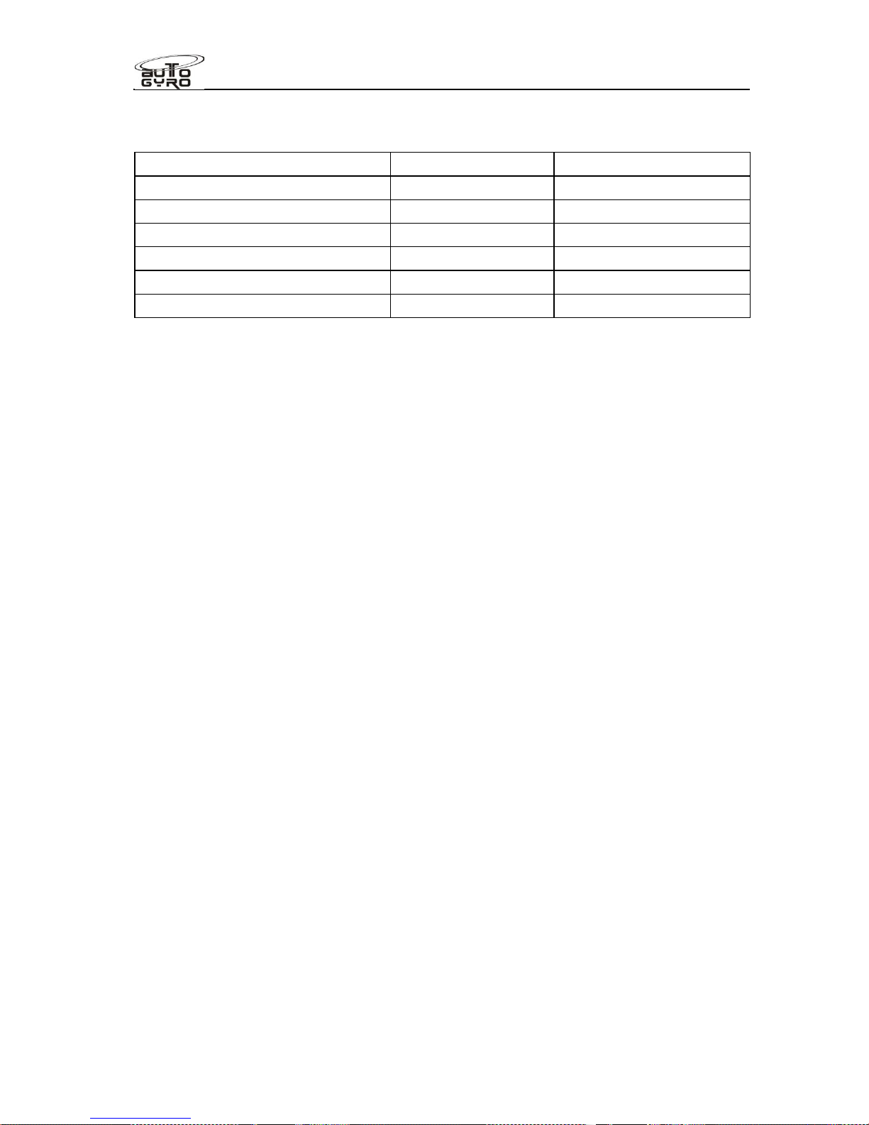
1.12 Unit Conversion
Multiply
by
to obtain
kts (knots) 1.852 km/h
km/h (kilometres per hour) 0.54 kts
mph (miles per hour) 1.61 km/h
km/h (kilometres per hour) 0.62 mph
ft (feet) 0.305 m
m (metres) 3.28 ft
Page 20

Flight Manual
Cavalon
SECTION
1
GENERAL
RSUK0287_POH_Cavalon Revision 3.0, Issue Date 06.04.16 1-8
1.13 Abbreviations and Terminology
ACL
Anti
-Collision Light
AGL
Above Ground Level
ATC
Air Traffic Control
CAS
CB
Calibrated AirSpeed – indicated speed corrected for installation errors
Circuit Breaker
ccw
Counter Clock Wise
CG
Centre of Gravity
CHT
Cylinder Head Temperature
CRP
Carbon Reinforced Plastic
CSP
Constant Speed Propeller
DA
Density Altitude
DULV
Deutscher UltraLeichtflugVerband e.V.
Empty Wt
Empty Weight of the gyroplane including oil, cooling liquid and unusable fuel
FOM
Flight and Operation Manual
G / g
G-loading as a factor of gravity
GEN
Generator
GPS
Global Positioning System
GRP
Glass Reinforced Plastic
hrs
hours
H/V
Height-Velocity
IAS
Indicated AirSpeed – airspeed values in this manual refer to indicated air speed
ICAO
International Civil Aviation Organization
In Hg
(Manifold) Pressure, corresponding to inch mercury
ISA
International Standard Atmosphere
JNP
JahresNachPrüfung – Annual Inspection
LED
Light Emitting Diode
LH
Left-Hand
LOEP
List Of Effective Pages
ltr
Litre
MAP
Manifold Absolute Pressure
MCP
Maximum Continuous Power
MTOW
Maximum Take-Off Weight (mass)
OAT
Outside Air Temperature
PA
Pressure Altitude
POH
Pilot Operating Handbook
RBT
Rotor Bearing Temperature
RH
Right-Hand
RO
N
Research Octane Number
RPM
Revolutions Per Minute
Page 21

Flight Manual
Cavalon
SECTION
1
GENERAL
RSUK0287_POH_Cavalon Revision 3.0, Issue Date 06.04.16 1-9
sqm
Square metres
TAS
True AirSpeed – calibrated airspeed corrected for air density
TCU
Turbo Control Unit (engine)
TOC
Table Of Contents
TO
P
Take-Off Power
V
A
Design maneuvering speed
V
B
Design speed for maximum gust intensity
VFR
Visual Flight Rules
V
H
Maximum level-flight speed at maximum continuous power
V
Hmin
Minimum level-flight speed
V
NE
Never-Exceed Speed – maximum speed that must never be exceeded
VOX
Voice Operated eXchange, means: voice activation (level)
VPP
Variable Pitch Propeller
VSI
Vertical Speed Indicator
V
X
Speed for best angle of climb
V
Y
Speed for best rate of climb and maximum endurance
W&B
Weight and Balance
yrs
years
Page 22

Page 23

Flight Manual
Cavalon
SECTION 2
LIMITATIONS
RSUK0287_POH_Cavalon Revision 2, Issue Date 24.06.2015 2 - i
CONTENTS
2.1 General ......................................................................................................... 2-1
2.2 Environmental Limitations.............................................................................. 2-3
2.3 Colour Code for Instrument Markings ............................................................ 2-3
2.4 Airspeed Limitations and Instrument Markings...............................................2-4
2.5 Rotor Speed Limitations and Instrument Markings.........................................2-4
2.6 Powerplant Limitations and Instrument Markings........................................... 2-5
2.7 Weight and Balance ......................................................................................2-7
2.7.1 Weight Limits............................................................................................ 2-7
2.7.2 Centre of Gravity (CG) Limits.................................................................... 2-7
2.7.3 Demonstrated Structural Load Factors...................................................... 2-8
2.8 Flight Crew .................................................................................................... 2-8
2.9 Kinds of Operation.........................................................................................2-8
2.10 Fuel ............................................................................................................... 2-9
2.10.1 Approved Fuel Grades......................................................................... 2-9
2.10.2 Fuel Tank Capacities ........................................................................... 2-9
2.10.3 Unusable Fuel...................................................................................... 2-9
2.11 Minimum Equipment...................................................................................... 2-9
2.12 Placards ...................................................................................................... 2-10
Page 24

Flight Manual
Cavalon
SECTION 2
LIMITATIONS
RSUK0287_POH_Cavalon Revision 2, Issue Date 24.06.2015 2 - ii
INTENTIONALLY LEFT BLANK
Page 25

Flight Manual
Cavalon
SECTION 2
LIMITATIONS
RSUK0287_POH_Cavalon Revision 3.0, Issue Date 06.04.16 2-1
LIMITATIONS
SECTION 2 -
This section contains operating limitations, instrument markings and basic placards which
are required for safe operation of the gyroplane, including its engine, and standard
equipment or systems.
2.1 General
WARNING
The operation of a gyroplane demands professional pilot instruction and
dedicated training on gyroplanes. The aircraft must only be flown by a properly
qualified and licensed pilot.
WARNING
Positive G load on the rotor must be maintained during all flight manoeuvres.
Do not perform any manoeuvres resulting in the sensation of feeling light or
near weightless.
WARNING
Smoking on board is prohibited!
CAUTION
This gyroplane has been designed and tested for a safe design load of 3.5g at
maximum take-off weight 500kg / 3.0g at maximum take-off weight 560kg. Note
that flying at high speeds in turbulent air, especially in combination with
aggressive manoeuvres or a steep turn, can easily create high loads on the
aircraft.
NOTE
This gyroplane does not comply with the terms of the international authority for
civil aviation (ICAO). Therefore, it is not permitted to operate it in international
airspace unless specific intergovernmental agreements allow the flight. The
reason for this is that there is no international common basis for gyroplanes
type approval.
Page 26

Flight Manual
Cavalon
SECTION 2
LIMITATIONS
RSUK0287_POH_Cavalon Revision 3.0, Issue Date 06.04.16 2-2
NOTE
During the approval process all required safe loads have been successfully
demonstrated. However, the gyroplane may be exposed to unpredictable and
high loads especially when operated on rough surfaces, such as an unprepared
grass strip. In this case it is even more essential to perform a thorough pre-
flight inspection and have components and parts replaced, where needed.
NOTE
The choice, selection and use of this particular aircraft for the purpose chosen
is at the sole discretion and responsibility of the owner/pilot. RotorSport UK
Ltd and AutoGyro GmbH take no responsibility for your decision to fly.
This aircraft is operated under a Permit to Fly, not a certificate of airworthiness.
This means that it is only allowed to be used for recreation, or flight training
(where allowed). It also means that the aircraft has not been certified to any
international standard, and that the components used in the aircraft are not
necessarily certified parts. Whilst the manufacturer takes great care to ensure
the parts are of appropriate quality, the level of guaranteed service is less than
that with a certified aircraft, and pilot operators must consider this in their flight
planning
In common with other aircraft of this type the Cavalon utilises a non-certified
engine. This means that there may be a higher risk of engine failure than in a
certified aircraft, with the associated risks of damage or injury as the result of
an unplanned landing. Therefore strict compliance with the engine
manufacturer’s maintenance schedules, operational procedures and any
additional instructions which may be given to you by RotorSport UK Ltd, on
behalf of the engine supplier, is essential. The aircraft must always be flown
with the risk of engine failure in mind, and must not be flown over any areas
where a forced landing cannot be safely executed.
Similarly the aircraft instruments (and other equipment) are non-certified.
Gauges may fail completely, or part fail such that a gauge may under or over-
read, or fluctuate. Good judgement must be used in monitoring instruments,
and timely action taken should a reading be in doubt.
Page 27

Flight Manual
Cavalon
SECTION 2
LIMITATIONS
RSUK0287_POH_Cavalon Revision 3.0, Issue Date 06.04.16 2-3
2.2 Environmental Limitations
Maximum wind speed or gust intensity......................................................40 kts
Maximum demonstrated crosswind component for take-off and landing....20 kts
Maximum tailwind component for take-off and landing ................................5 kts
Maximum demonstrated operating altitude........................................... 10,000 ft
Temperature ............................................................................... - 20 to + 40 °C
CAUTION
When operating at high altitudes the engine performance is diminished, such
that there is little available power if operating at 10,000ft with a 912ULS engine.
Care must be used operating a 914UL engine at high altitudes, as it is possible
to overspeed the engine in level flight at max power. Take care to monitor the
engine rpm gauge.
WARNING
Do not consider flying in the likelihood of severe weather. Thunderstorms may
develop rapidly with the risk of heavy precipitation or hail, severe turbulence
with strong vertical air movements, and lightning strike. If, despite proper flight
planning, a thunderstorm should be encountered, consider a precautionary
landing to avoid the squall line. A lightning strike may damage the main rotor
bearing. Thorough inspection and maintenance after lightning strike must be
performed.
2.3 Colour Code for Instrument Markings
R
ed
Operating limits. Pointer should not enter red during normal operation
Y
ellow
Precautionary or special operating procedure range
G
reen
Normal operating range
Page 28
Flight Manual
Cavalon
SECTION 2
LIMITATIONS
RSUK0287_POH_Cavalon Revision 3.0, Issue Date 06.04.16 2-4
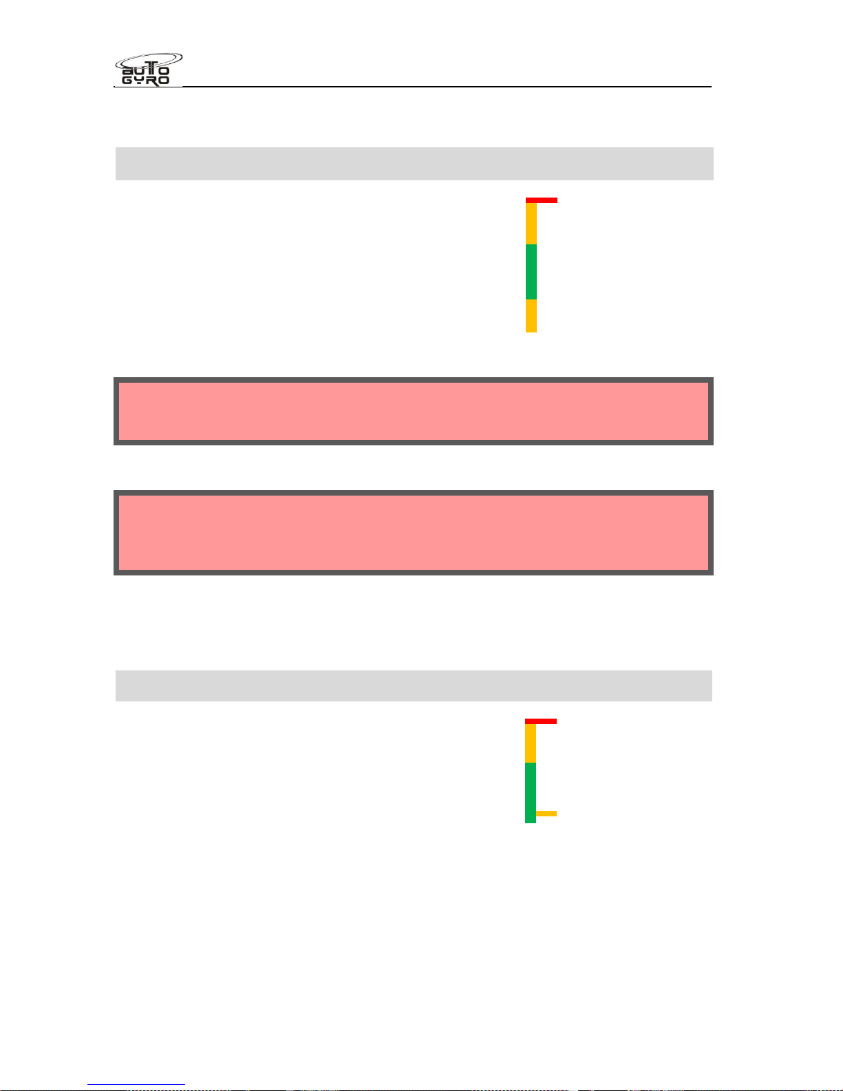
2.4 Airspeed Limitations and Instrument Markings
Air Speed Marking
VNENever Exceed Speed
Red radial
160 km/h (100mph)
Yellow arc
130 – 160 km/h (80-
100mph
Recommended manoeuvring speed range
80mph is the recommended maximum
speed in strong gust conditions
Green arc
30 -
130 km/h (20-
80mph
Yellow arc
0 – 30 km/h (0-
20mph)
WARNING
The maximum speed VNEmust never be exceeded!
WARNING
Sudden or large forward control inputs must be avoided at all times in flight. Do
not exceed 80mph when flying through turbulence, high gusts or rough winds!
2.5 Rotor Speed Limitations and Instrument Markings
Rotor Speed Marking
Rotor speed limit
Red radial
610 RPM
Rotor speed caution range Yellow arc 550 – 610 RPM
Normal range Green arc 200 – 550 RPM
Maximum pre-rotation speed
Yellow radial
220 RPM
Page 29
Flight Manual
Cavalon
SECTION 2
LIMITATIONS
RSUK0287_POH_Cavalon Revision 3.0, Issue Date 06.04.16 2-5
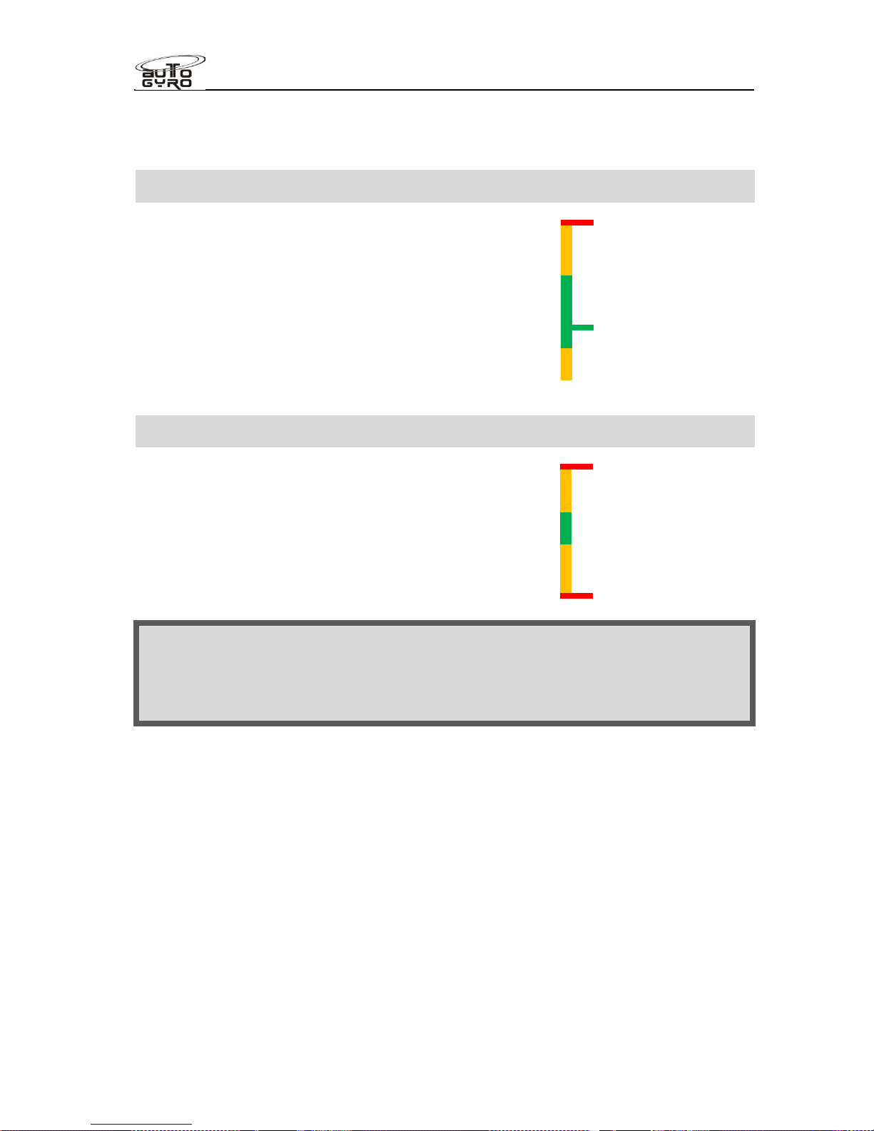
2.6 Powerplant Limitations and Instrument Markings
Engine Speed Marking
Maximum engine speed
Red radial
5800 RPM
5 minute take-off power regime Yellow arc 5500 – 5800 RPM
Maximum continuous power
Green arc
1400 –
5500 RPM
Recommended pre-rotation clutch speed
Green radial
2000 RPM*
Yellow arc 0 – 1400 RPM
Engine Oil Temperature Marking
Maximum oil temperature
Red radial
130 °C
Yellow arc 110 – 130 °C
Normal range
Green arc 90 – 110 °C
Yellow arc 50 – 90 °C
Minimum oil temperature
Red radial
50 °C
NOTE
Oil temperature is measured in the oil tank, and is the temperature of the oil as
it exits the engine. After the oil is cooled in the oil cooler, and returned to the
engine.
Page 30
Flight Manual
Cavalon
SECTION 2
LIMITATIONS
RSUK0287_POH_Cavalon Revision 3.0, Issue Date 06.04.16 2-6
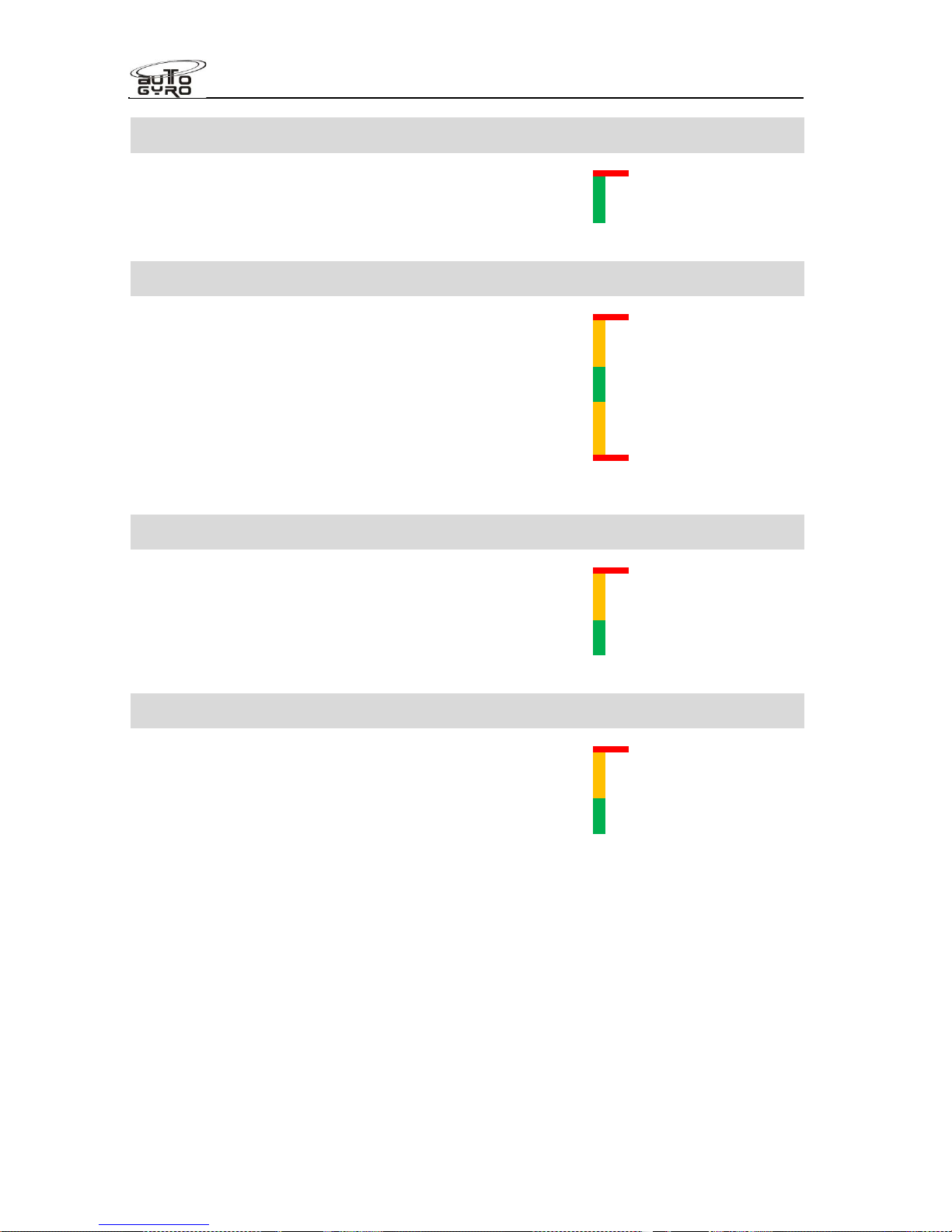
Cylinder Head Temperature Marking
Maximum cylinder head temperature
Red radial
135 °C
Green arc 50 – 135 °C
Engine Oil Pressure Marking
Maximum oil pressure
Red radial
7 bar
Yellow arc 5 – 7 bar
Normal range
Green arc 2 – 5 bar
Yellow arc 0.8 – 2 bar
Minimum oil pressure
Red radial
0.8 bar
Manifold Pressure* ROTAX 912 ULS Marking
Maximum manifold pressure
Red radial
31 In Hg
Yellow arc 27 – 31 In Hg
Maximum continuous MAP
Green arc
0 -
27 In Hg
Manifold Pressure* ROTAX 914 UL Marking
Maximum manifold pressure
Red radial
39 In Hg
Yellow arc 31 – 39 In Hg
Maximum continuous MAP
Green arc
0 -
31 In Hg
* Applicable only if installed, MAP gauge is optional. MAP limits do not apply for 912ULS engine
speeds above 5100 RPM. 914UL limits are controlled by the engine managements system
Page 31

Flight Manual
Cavalon
SECTION 2
LIMITATIONS
RSUK0287_POH_Cavalon Revision 3.0, Issue Date 06.04.16 2-7
2.7 Weight and Balance
2.7.1 Weight Limits
Maximum take-off weight (MTOW):......................................................... 500 kg
If MC-281 embodied Maximum take-off weight (MTOW)......................... 560 kg
Maximum empty weight …………………………311kg (914UL) 309kg (912ULS)
CAUTION
The take-off weight is the total weight of the gyroplane including empty weight,
optional/additional equipment, occupants, fuel, and luggage at take-off. The
maximum value specified above must never be exceeded.
Maximum weight in RH seat (incl. compartment behind seat): ............... 110 kg
Maximum weight in LH seat (incl. compartment behind seat): ................ 110 kg
Maximum total weight in cockpit (both seats + compartments):............... 200 kg
Minimum total weight in both seats: .......................................................... 65 kg
NOTE
Pilots in the right hand seat weighing less than 65 kg must carry corresponding
ballast during solo operation (which may be located in the baggage
compartment, around the occupant in a form such as sheet lead under the seat
cushion, or securely restrained on the second seat).
Storage compartments behind seats
Maximum weight in each storage compartment (2 ea.) ............................. 10 kg
NOTE
When loaded, the weight in each storage compartment has to be deducted from
the maximum weight in the respective seat.
2.7.2 Centre of Gravity (CG) Limits
The centre of gravity is considered to be within limits if all weight limits above are respected.
For details see SECTION 6 of this manual.
For reference, the limits approved during the aircraft UK type approval are 540 to 345mm
forward of the mainwheel datum, and 900 to 750 above the CG datum (the mainwheel axle
is the 0 CG datum in x and z) when fitted with the RAO rotorsystem II, and 940 to 750
above the CG datum when fitted with the TOPP rotorsystem II. These limits are unchanged
when MC-281 “Cavalon upgrade to 560kg MTOW” is embodied.
Page 32

Flight Manual
Cavalon
SECTION 2
LIMITATIONS
RSUK0287_POH_Cavalon Revision 3.0, Issue Date 06.04.16 2-8
2.7.3 Demonstrated Structural Load Factors
Demonstrated positive load factor (500 kg)............................................. + 3.5 g
Demonstrated negative load factor (500 kg) – structural limit...................... - 1 g
If MC-281 “Cavalon upgrade to 560kg MTOW” is embodied then
Demonstrated positive load factor (560 kg)............................................. + 3.0 g
Demonstrated negative load factor (560 kg) – structural limit................... - 0.5 g
Important note: the indication of a demonstrated negative load factor represents a
structural limit only. In flight, the limitations (see 2.9) have to be respected at all times.
2.8 Flight Crew
Minimum crew is one pilot in the RH seat.
Harness in the LH seat must be fastened and tight, if not occupied.
The LH flight controls must never be restricted by passenger or objects. Passengers must
be briefed accordingly.
2.9 Kinds of Operation
Only day VFR operation is approved!
Aerobatic flight is prohibited!
NOTE
Manoeuvres involving bank angles of more than 60° are considered to be
aerobatic flight.
Low-G manoeuvres are prohibited!
WARNING
Any maneuver resulting in a low-G (near weightless) condition can result in a
catastrophic loss of lateral/roll control in conjunction with rapid main rotor
RPM decrease. Always maintain adequate load on the rotor and avoid
aggressive forward control input performed from level flight or following a pull-
up.
Page 33

Flight Manual
Cavalon
SECTION 2
LIMITATIONS
RSUK0287_POH_Cavalon Revision 3.0, Issue Date 06.04.16 2-9
Excessive side-slip is prohibited!
WARNING
Side slip may be performed only with proper training and within safe
boundaries. Use gentle pedal input for initiation and stabilization. Do not rely
on airspeed indication in side slip. Never perform abrupt control stick input into
the direction of motion. Be aware that excessive side slip particularly in
strong/gusty conditions may result in an uncontrollable and unrecoverable
attitude.
Flight in icing conditions is prohibited!
NOTE
Icing may occur even at temperatures above freezing!
Operation in strong gusts or wind speeds of more than 72 km/h (40 kts) is prohibited!
2.10 Fuel
2.10.1 Approved Fuel Grades
Preferred fuel
UL91
or EN 228 Super or EN228 Super plus (min. ROZ 95)
Alternative fuel
AVGAS 100 LL (ASTM D910)
For operational constraints and maintenance aspects when using preferred fuel and
alternative fuel, refer to the engine manufacturer’s manual.
2.10.2 Fuel Tank Capacities
Maximum tank capacity............................................................................ 103 ltr
2.10.3 Unusable Fuel
Unusable fuel quantity ................................................................................. 3 ltr
2.11 Minimum Equipment
The following equipment must be operative for flight:
Air speed indicator
Page 34

Flight Manual
Cavalon
SECTION 2
LIMITATIONS
RSUK0287_POH_Cavalon Revision 3.0, Issue Date 06.04.16 2-10
Altimeter
Compass
Side slip indicator
Rotor RPM indicator
Engine rpm gauge
Engine instruments (oil pressure, RPM, CHT)
Pre-rotator
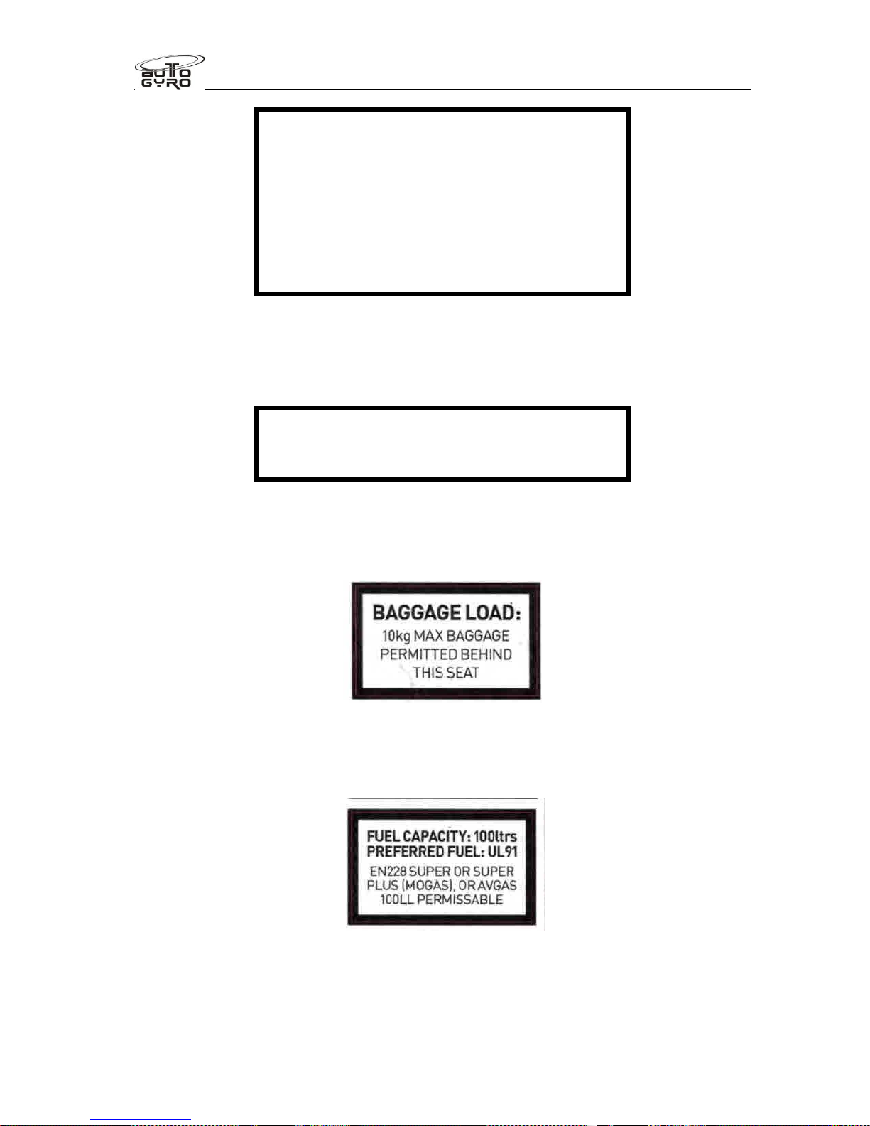
2.12 Placards
In clear view of the pilot on centre panel
:
MTOW is 500kg,
or if MC-281 embodied then 560kg
OPERATING LIMITATIONS
Aerobatic Limitations
Aerobatic manoeuvres are prohibited.
Manoeuvres involving a deliberate reduction in
normal ‘g’ shall be avoided.
CG Range Limits (Gyroplane) – refer to Pilots
Handbook data.
Page 35
Flight Manual
Cavalon
SECTION 2
LIMITATIONS
RSUK0287_POH_Cavalon Revision 3.0, Issue Date 06.04.16 2-11
Airspeed Limitations
Maximum Indicated Airspeed (Vne): 100mph
Other Limitations
This aircraft shall be flown by day and under
Visual Flight Rules only.
Smoking in the aircraft is prohibited
Occupant warning (beside both seat entry, and on centre panel):
OCCUPANT WARNING
This aircraft has not been certified to an
international requirement
At each storage compartment behind seats:
At fuel filler neck:
Page 36
Flight Manual
Cavalon
SECTION 2
LIMITATIONS
RSUK0287_POH_Cavalon Revision 3.0, Issue Date 06.04.16 2-12
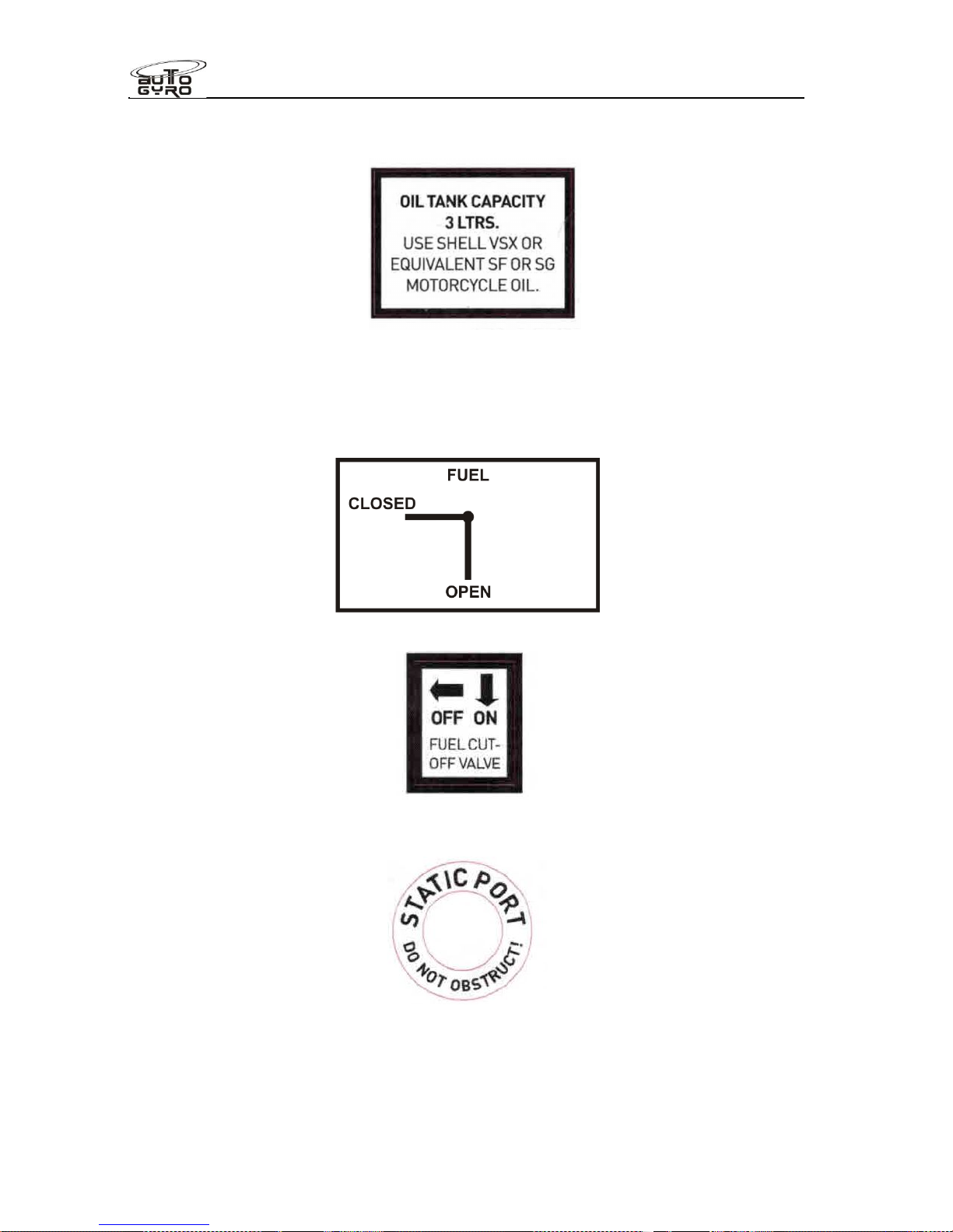
At oil filler access panel:
At fuel shut-off valve:
Or
At both static ports:
Fitted to the doors inside
Page 37
Flight Manual
Cavalon
SECTION 2
LIMITATIONS
RSUK0287_POH_Cavalon Revision 3.0, Issue Date 06.04.16 2-13
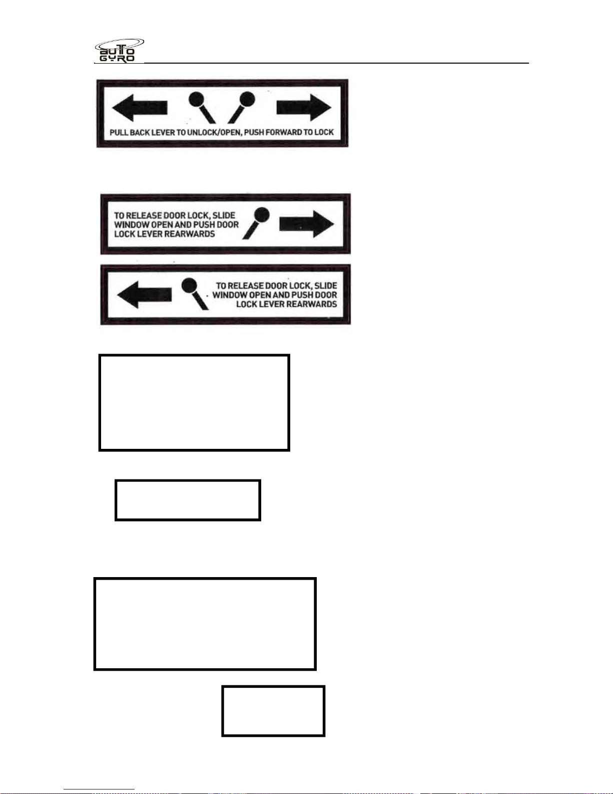
Fitted to the doors outside
Fitted to the instrument panel
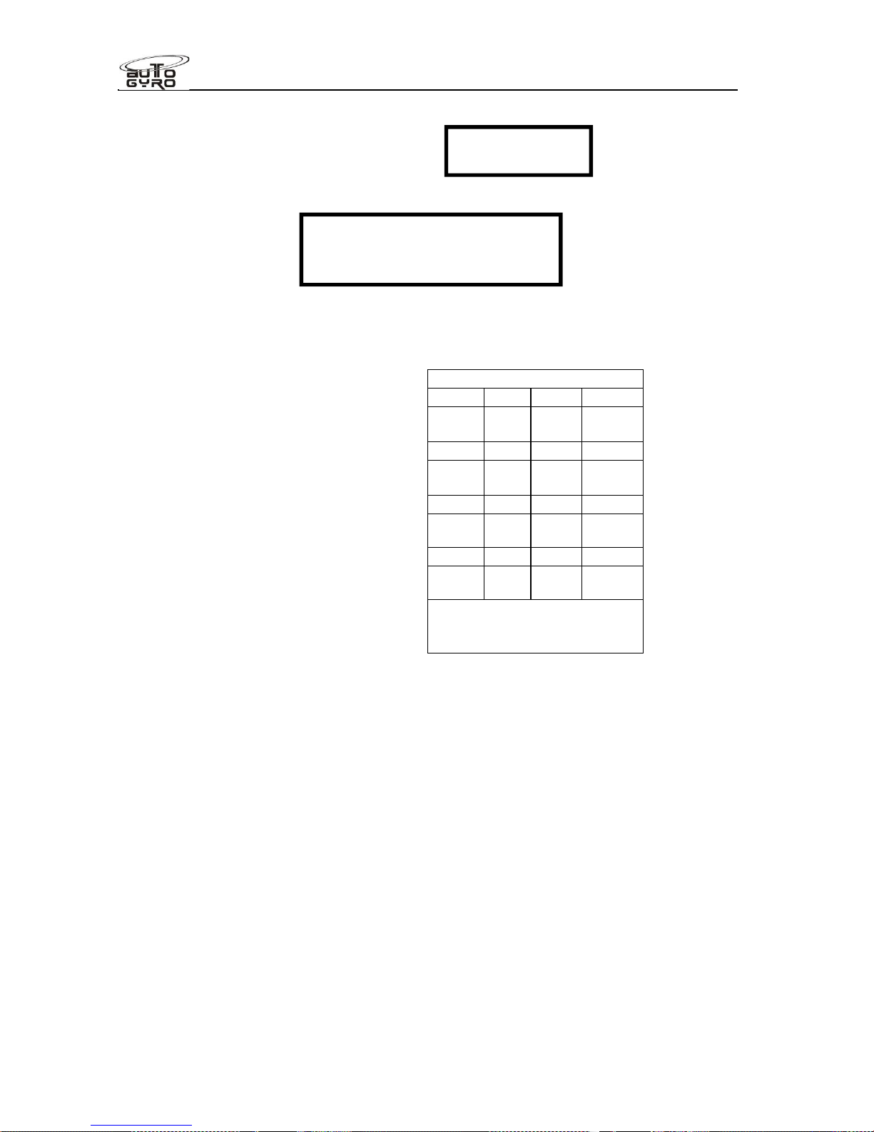
GPS placard (where a GPS, Ipad or equivalent device is fitted)
(Placard may be a different shape)
Fire warning lamp:
Continuously lit Low Volt lamp
indicates electrical demand
exceeds supply, and the battery
is being drained. If lit in flight,
reduce demand until unlit. If not
possible, expedite landing.
Pre-rotator & rotor
brake interlock release
Do not rely on this display. Day VMC
only. GPS unit not for navigational use.
The unit, software & charts are not
approved or certified to any national
standard. Warning! Charts or software
may not be up to date.
FIRE WARNING
When flashing
RED
Page 38
Flight Manual
Cavalon
SECTION 2
LIMITATIONS
RSUK0287_POH_Cavalon Revision 3.0, Issue Date 06.04.16 2-14
On keel tube fin (where fitted, both sides)
Circuit breakers
- Other
If the compass deviation is more than 5° on all headings, then a deviation placard
must be present.
The aircraft is fitted with a permanently attached fireproof plate with the aircraft registration
number and serial no. marked on it, on front of the instrument panel.
The registration letters are placed high on the tail fin, and are 60cm long, 30cm high. This
has been accepted as best practice compliance to CAP523, the CAA standard for aircraft
registration. Alternative markings and position of markings is acceptable provided they
comply with this standard.
Note that all placards must have the same units of measure as the instruments.
COMPASS DEVIATION
For N 30 60
Set
For E 120 150
Set
For S 210 240
Set
For W 300 330
Set
Calibration by: date:
CIRCUIT BREAKERS
Only attempt to reset (once) if
essential for continued safe flight
NO STEP
Page 39

Flight Manual
Cavalon
SECTION 3
EMERGENCY PROCEDURES
RSUK0287_POH_Cavalon Revision 2, Issue Date 24.06.2015 3 - i
CONTENTS
3.1 Engine Failure ............................................................................................... 3-1
3.2 Air Restart Procedure .................................................................................... 3-2
3.3 Landing into Trees or High Vegetation........................................................... 3-2
3.4 Degradation of Engine Power ........................................................................ 3-2
3.5 Evacuating the Aircraft...................................................................................3-3
3.6 Smoke and Fire ............................................................................................. 3-3
3.7 Off-field Landing ............................................................................................ 3-3
3.8 Flight Control Malfunction..............................................................................3-4
3.8.1 Engine Power Control / Throttle................................................................ 3-4
3.8.2 Rudder Malfunction................................................................................... 3-4
3.8.3 Rotor Head Control................................................................................... 3-4
3.8.4 Trim runaway............................................................................................ 3-5
3.9 Pitch oscillation recovery ...............................................................................3-5
3.10 Vibration........................................................................................................ 3-5
3.11 Door open in flight. ........................................................................................ 3-7
3.12 Warning and Caution Lights........................................................................... 3-8
3.12.1 GEN or Low Volt Indicator Light ...........................................................3-8
3.12.2 Low Volt...............................................................................................3-8
3.12.3 BOOST WARN Light ‘Boost’ (red) - only ROTAX 914 UL.....................3-9
3.12.4 BOOST CAUTION Light ‘Caution’ (orange) - only ROTAX 914 UL....... 3-9
3.12.5 Fire ......................................................................................................3-9
3.12.6 Low Fuel (if installed)......................................................................... 3-10
3.12.7 Deleted. ............................................................................................. 3-10
3.12.8 Fan .................................................................................................... 3-10
3.13 Parameters out of Limits.............................................................................. 3-10
3.14 Rotor Bearing Temperature......................................................................... 3-10
3.15 Loss of Visibility........................................................................................... 3-11
3.16 (not used) .................................................................................................... 3-11
3.17 Rotor Icing................................................................................................... 3-11
3.18 Landing with a Deflated Tyre ....................................................................... 3-11
3.19 Not used...................................................................................................... 3-12
3.20 Alternative Method of Engine Shut-down ..................................................... 3-12
Page 40

Flight Manual
Cavalon
SECTION 3
EMERGENCY PROCEDURES
RSUK0287_POH_Cavalon Revision 2, Issue Date 24.06.2015 3 - ii
INTENTIONALLY LEFT BLANK
Page 41

Flight Manual
Cavalon
SECTION 3
EMERGENCY PROCEDURES
RSUK0287_POH_Cavalon Revision 2, Issue Date 24.06.2015 3-1
EMERGENCY PROCEDURES
SECTION 3 -
This chapter contains the check lists and procedures to be executed in emergency
situations.
Emergencies due to defects of the gyroplane or its engine are extremely unlikely if the
aircraft is checked thoroughly before each flight, and maintained in accordance with the
AMM. If there an emergency does occur, follow the appropriate guidelines below. These
procedures do not replace the pilot’s appreciation of the individual situation.
3.1 Engine Failure
In case of an engine failure the following action is recommended:
Engine failure during take-off run
Maintain directional control using sensitive but appropriate pedal input
With the rotor/stick remaining aft, let gyroplane decelerate. Wheel brakes may be
used to assist
At walking speed level-off rotor disc, use wheel brakes and bring rotor to a stop
Engine failure after lift-off and below 150 ft AGL
The climb-out should be performed according to the Height-Velocity-Diagram
in CHAPTER 5
When engine failure occurs, immediately lower nose to enter glide attitude
Continue straight ahead – a 180 turn back to the airfield may be a bad option
Maintain airspeed until ground is approached, then perform flare
Depending on final approach speed be prepared to flare more distinctly than normal
Engine failure at or above 150 ft AGL
Consider wind speed and direction
Select a suitable landing site
If time allows, a restart may be attempted, see “Air restart procedure” below
Perform a landing into wind and/or upslope if possible
Prior to touch-down switch OFF Main Switch
WARNING
Engine failure at high speed, hands-off, will result in a nose drop, requiring
pilot intervention to raise the nose. At light weight the nose drop will be rapid.
WARNING
Always plan your route to remain within safe gliding distance to areas where a
safe forced landing can be performed in case of an engine failure. A landing in
high trees or open waters may end fatally.
Page 42

Flight Manual
Cavalon
SECTION 3
EMERGENCY PROCEDURES
RSUK0287_POH_Cavalon Revision 2, Issue Date 24.06.2015 3-2
NOTE
The best engine-off glide ratio is about 1:3 at 90 km/h (55-60mph). Depending
on a possible headwind the glide may be extended by slightly increasing
airspeed. It is heavily recommended to train your forced landing capabilities
regularly, preferably with a qualified flight instructor.
3.2 Air Restart Procedure
Check fuel valve OPEN
Check fuel pump(s) ON
Check both magnetos ON
Throttle slightly open
With the left hand, turn the Main Switch/Starter key completely to OFF, then START
If possible, allow engine and oil to warm-up before full power is applied
NOTE
The starter interlock function prevents inadvertent starter engagement. Before
attempting an engine start, the interlock must be reset by turning the Main
Switch/Starter key to OFF.
3.3 Landing into Trees or High Vegetation
Assume the surface of the treetops or vegetation as level
Plan touch-down and flare with minimum ground speed and minimum rate of descent
As soon as the wheels contact the vegetation bring the rotor disc to level attitude to
avoid partial blade tip contact with vegetation
Shut down engine by switching magnetos OFF and master switch OFF
3.4 Degradation of Engine Power
A gradual decay in engine RPM, accompanied by a rough running engine or even vibration
may be an indicator for carburettor icing. In this case, continue with a high power setting
and change altitude into air which is less susceptible to carburettor icing.
If the situation cannot be corrected be prepared for further loss of power and ultimately
engine failure.
NOTE
The phenomenon of carburettor icing is extremely unlikely with this engine
type as the carburettor inlets draw warm air from within the engine
compartment. Note that this arrangement can work properly only when the
engine is at operating temperature.
Page 43

Flight Manual
Cavalon
SECTION 3
EMERGENCY PROCEDURES
RSUK0287_POH_Cavalon Revision 2, Issue Date 24.06.2015 3-3
3.5 Evacuating the Aircraft
In normal circumstances occupants should never leave the aircraft while the propeller or the
rotors are turning. If abandoning the aircraft in an emergency the pilot should turn off the
engine magneto switches and turn the master switch to “OFF” if this can be done without
endangering the occupants.
If abandoning the aircraft with either the propeller and/or the rotors turning the occupants
should follow a path in line with the nose of the aircraft, to minimise the risk of being struck
by either the rotor or the propeller.
Occupants should be briefed before flight on emergency evacuation procedures, including:
Actions to be taken in the event of a forced landing
Operation of the seat harness
Disconnection of any intercom leads or other connections to the aircraft
How to open the doors
How to safely exit and move away from the aircraft
3.6 Smoke and Fire
Indications of smoke should be treated in the same way as a fire.
NOTE
The fire warning system will illuminate a RED flashing warning lamp on the
panel when the special cable in the engine bay has melted due to the effect of
high temperatures (fire). This lamp shows solid red when a fault is detected.
In case of fire the following action is recommended:
Smoke or fire on ground
Both magnetos OFF and master switch OFF to shut-down engine and fuel pumps
Close fuel shut-off valve
Evacuate aircraft
Extinguish fire and have damage inspected
Fire in flight
Open ventilation for fresh air
Initiate an emergency landing
Initiate emergency call, if time and situation permits
As soon as a power-off landing can be assured, close fuel shut-off valve, shut down
engine by switching magnetos OFF and master switch OFF
Continue procedure as described in “Engine Failure” and “Smoke or fire on ground”
3.7 Off-field Landing
A precautionary landing at a non-prepared site may be performed at pilot’s discretion in
order to avoid unexpected weather, in case of severe illness of the pilot or a passenger, or if
technical defects are suspected, for example sudden and severe rotor vibrations.
Page 44

Flight Manual
Cavalon
SECTION 3
EMERGENCY PROCEDURES
RSUK0287_POH_Cavalon Revision 2, Issue Date 24.06.2015 3-4
Select a suitable landing site from safe altitude, considering slope, wind speed and
direction
Fly a reconnaissance pattern to check for obstacles, especially power lines, wires,
and cables in the approach and go-around path
Overfly the landing site to check for obstructions such as fences, ditches, rocks,
height of vegetation, and select most suitable touch-down zone
Perform a normal approach and touch-down into wind with minimal ground speed
3.8 Flight Control Malfunction
In case of a flight control failure the gyroplane can be controlled with the remaining primary
and secondary controls, including power and trim. An immediate reduction of power, and
corresponding reduction in speed may be necessary to avoid pitch oscillations (phugoid) or
other effects affecting dynamic or static stability. Navigate to a suitable landing site with
wide and shallow turns and approach against the wind.
3.8.1 Engine Power Control / Throttle
Throttle jammed open or max
Navigate to a suitable landing site with the power set. If over safe terrain, magneto switches
may be used to control power. When within gliding distance to the selected landing site,
shut-down engine to perform a power-off landing as per Emergency Procedure “Engine
failure”.
NOTE
In case of a control cable breakage the carburettor will be automatically set to
full throttle position.
Throttle jammed closed
Land as per Emergency Procedure “Engine failure”. Residual power may be used to extend
the glide.
3.8.2 Rudder Malfunction
In case of a stuck or loose rudder, continue flight to a suitable, preferably wide landing site
that allows a landing into the wind. If necessary reduce power to avoid excessive side slip.
Align gyroplane prior to touch-down, using engine torque or lateral control input to the side
where the nose is pointed.
3.8.3 Rotor Head Control
In case of a rotor head control malfunction, control pitch attitude using careful trim input and
power setting. Use rudder for directional control and for shallow turns. In some conditions it
may be appropriate to reduce power/speed in order to avoid phugoid effects or a possible
negative yaw-roll coupling. Approach landing site with wide and shallow turns.
Page 45

Flight Manual
Cavalon
SECTION 3
EMERGENCY PROCEDURES
RSUK0287_POH_Cavalon Revision 2, Issue Date 24.06.2015 3-5
3.8.4 Trim runaway
Failure of a trim selector switch or pneumatic valve may result in trim runaway (where the
trim system runs to one extreme and pushes the control stick accordingly). Although the
average pilot is able to resist the out-of-trim stick force and continue to fly the aircraft it may
be possible to reduce the stick load by intervention:
(i) High forward stick load required to prevent aircraft nose rising (this will be
coincident with a high air-pressure reading) – briefly turn the Flight/Brake selector
to “Brake” to deplete system air pressure. If the air compressor is heard to start
and the pressure rises again then pull the circuit-breaker marked “Comp” to stop
the compressor. Repeat the brief selection of “Brake” to deplete system air
pressure as required.
(ii) High aft stick load required to prevent aircraft diving (this will be coincident with
low or zero air pressure) – check “Comp” circuit breaker, if activated push to reset
then try to trim aircraft nose-up. If unsuccessful then continue to expedited
landing. Note: reset the circuit-breaker once only.
(iii) High roll-left or roll-right stick load required to maintain balanced flight (coincident
with high air-pressure reading). Pull the “Comp” circuit breaker to prevent further
increase in air pressure and attempt to re-trim. If unsuccessful then continue to
expedited landing. Do not select “Brake” in an attempt to reduce air pressure as
this will disturb the pitch trim (in which the out-of-trim forces are significantly
higher)
3.9 Pitch oscillation recovery
There are generally two types of pitch oscillation: that caused by pilot over control (‘PIO,
Pilot Induced Oscillation’) and that caused by aerodynamic oscillation.
PIO is not generally found on two seat gyroplanes due their inherent stability. It is initiated
by the pilot over-controlling the stick. If a situation develops where a divergent aircraft
pitching oscillation is occurring in sympathy with fore-aft control stick inputs, firstly stop the
control input – do NOT try to control PIO with the stick.
For both situations, smoothly closing the throttle whilst maintaining a level flight attitude will
return the aircraft to a stable, slow speed condition very quickly, from which the pilot can
recover to normal flight.
Recovery from PIO or aerodynamic oscillation can result in height loss.
3.10 Vibration
A gyroplane is subject to a number of out of balance forces which will generate different
levels of vibration depending on the engine and rotor rpms, and on loading conditions.
Rotors are normally balanced two seated, so a reduction in occupant loading will naturally
change the rotor response.
1. Engine and propeller. Vibration in this area will change with engine rpm, and can
therefore be affected and isolated by the pilot. The propeller is normally balanced to less
than 0.1ips, meaning low vibration. Vibration will increase as the propeller gets dirty, and will
also increase if damaged. A sudden change in flight will indicate a fault has developed,
Page 46

Flight Manual
Cavalon
SECTION 3
EMERGENCY PROCEDURES
RSUK0287_POH_Cavalon Revision 2, Issue Date 24.06.2015 3-6
either through an impact (loose luggage, bird strike etc. passing through the propeller) or by
some mechanical failure. In the event the pilot should make a precautionary landing for
evaluation. Propeller damage may also be evident from a change in noise level.
Upon landing, carefully check the propeller for damage, loose bolts or evidence of
mechanical failure within the prop or engine. Especially check the engine to engine bearer
connections, and the engine bearer to airframe connections.
2. Rotor.
Rotors will vibrate in flight due to tracking errors (side to side stick shake), rotor CG
misalignment with the axis of the bearing in the flat plane (oscillatory stick shake), and also
in the vertical plane (two per rev shake). The amount of shake will not suddenly change in
flight or between flights unless there has been mechanical failure, external influence or rotor
strike.
Vibration will increase (and performance decrease dramatically) with dirt build up on the
rotor blades, so before any analysis make sure they are clean.
If there is a change in vibration in flight make a precautionary landing and investigate. If on
rotor startup, stop and investigate.
Check items:
Rotor impact with tail of aircraft.
Hanger damage e.g. twist or distortion of trailing edge.
Blade bent from ground handling.
If after a recent re-assembly of the rotor, that the blades and hubs are serial-number
matched, and that the shim washers are correctly matched to the hub bar and rotor tower.
A reduction in vibration may be caused by increased flexibility between the rotor head and
the occupant. This may be control system looseness, so check all system joints for
tightness, and also for cracks at the base of the mast. Check security of all fastenings
between the rotor and the pilot
3.11
OTHER EQUIPMENT FAILURE
Good judgement must be used in monitoring instruments, and timely action taken should a
reading be in doubt. If in doubt, make a precautionary landing and resolve the issue rather
than continuing a flight.
Actions recommended:
ASI failure: In level flight fly with an engine rpm of 4,200 lightly laden to 5,000 heavily laden
which will give approx 60 to 80mph. When descending (nose down) throttle back to approx
3,000 to 3,500rpm to prevent overspeed. Continue to your designated landing site,
maintaining speed for a flare on landing in the final descent. Leave plenty of space to land
in should the flare be prolonged. Experience will aid judgement of the best engine rpm to
maintain to match the desired flight speed and payload.
Altimeter failure: In a gyroplane it is reasonably easy to judge height. If in controlled
airspace ensure the controlling authority is informed to prevent traffic conflict. Otherwise
continue to a safe landing using navigational skills to avoid potential collisions.
Compass failure: Resort to map, aided by GPS if available, fly at a speed to suit
navigational requirements or make a precautionary landing if unable to identify position.
Rotor RPM gauge failure: This is not essential for safe flight, and rotor rpm cannot normally
be affected in flight unless significant “g” or negative “g” is exerted – and then will only
provide an indication of the rpm. If failed in flight, repair on landing
Engine RPM: The engine is rpm self-limiting by propeller pitch in flight. If the gauge fails,
replace on landing. Use audio cues to establish rpm
Oil pressure, oil temp and water temp. A failure of one gauge can indicate an engine fault or
simply a gauge fault. Watching the other gauges will indicate the likely failure mode.
For example,
Page 47

Flight Manual
Cavalon
SECTION 3
EMERGENCY PROCEDURES
RSUK0287_POH_Cavalon Revision 2, Issue Date 24.06.2015 3-7
1. Gauge suddenly goes to full scale deflection, other gauges reading normally –
likely gauge fault
2. Oil pressure falls to zero, possible loss of pressure. Stop engine, make
precautionary landing
3. Water temp gradually or suddenly rises above max temp. Possible loss of
coolant. Stop engine, make precautionary landing
4. Oil temp suddenly falls to zero, other gauges reading normal – probable gauge
failure.
5. Oil temp rises above maximum, other gauges normal – possible very low oil level,
blocked radiator or thermostat. Stop engine, make precautionary landing.
6. Fuel level gauge suddenly falls to zero or FSD. Probable gauge failure, but
always cross check to predicted fuel burn. Low fuel light will light as a backup.
Sudden, large deflections are normally unlikely, with the exception of loss of pressure
readings.
3.11 Door open in flight.
A door open in flight is NOT catastrophic. The door hinge line is angled to the oncoming
airflow such that if left open before take-off, or opened in flight, the oncoming airflow will
naturally close the door.
Note, yawing the aircraft such that the open door is downwind will allow the door to open
more, but on straightening out the oncoming airflow closes the door. If the yaw is such that
the open door is upwind, then the oncoming airflow keeps the door firmly shut.
In the event of this occurrence, fly the aircraft and ignore the open door until it is safe to lock
it. This will be either on the ground, by a passenger (if it is on their side) or by slowing and
trimming the aircraft at a safe speed that allows the pilot to release hand(s) for the closure
task.
Page 48

Flight Manual
Cavalon
SECTION 3
EMERGENCY PROCEDURES
RSUK0287_POH_Cavalon Revision 2, Issue Date 24.06.2015 3-8
3.12 Warning and Caution Lights
3.12.1 GEN or Low Volt Indicator Light
The GEN lamp, when lit, indicates that there is no voltage being supplied from the
regulator circuit to the battery
.
It is normally lit when the engine is stationary or at very low rpm.
It is normally not lit in flight, but may be seen to pulse gently in low light conditions.
The LOW VOLT lamp, when lit, indicates that the available voltage from the battery has
dropped below 12v,
If both lamps are on with the engine running at more than 2,500rpm, then it is likely that the
charging circuit has failed, and that the aircraft is operating on battery power alone.
If only the LOW VOLT lamp is lit, then the aircraft voltage demand has exceeded supply,
and demand must be reduced in order for the lamp to extinguish. NOTE! When lit, this lamp
also indicates that the strobes, nav lights,landing lights and 12v socket (where fitted) have
been turned off automatically, with automatic reconnection when the supply exceeds
demand.
Required Action
ROTAX 912 ULS: If any of the indicators are permanently lit, switch off all unnecessary
electrical consumers and land at the nearest airfield where maintenance can be performed.
The battery is expected, if in good condition, to provide 30minutes of reserve power to
supply the aircraft instrumentation and avionics, after which time electrical equipment may
cease to function.
ROTAX 914 UL: If any of the indicators are permanently lit, switch off all
unnecessary electrical consumers and perform a precautionary landing within 30minutes.
The battery is expected, if in good condition, to provide 30minutes of reserve power to
supply the aircraft fuel pump, instrumentation and avionics, after which time electrical
equipment may cease to function and fuel supply to the engine lost. Be prepared for an
engine failure.
Further information (914UL).
No power in the cabin indicates either the main circuit fuse has failed, or that the
battery has failed and the pump protection relay has opened. In this case the P1
primary fuel pump remains powered by the regulator directly, maintaining fuel supply
to the engine. The turbo control unit is not powered in this instance, and will remain
in whatever position it was in when power was lost – so mixture and manifold
pressure control will be lost. Take care to only use the minimum power required to
land safely to prevent engine damage.
In this case the primary fuel pump will continue to run until the engine alternator
stops providing electrical energy. If required, fuel supply can be shut off via the fuel
cock located behind the seats.
NOTE
A gently pulsed GEN indicator light (visible in low light conditions) is normal
and indicates proper function of the generator.
3.12.2 Low Volt
Page 49

Flight Manual
Cavalon
SECTION 3
EMERGENCY PROCEDURES
RSUK0287_POH_Cavalon Revision 2, Issue Date 24.06.2015 3-9
Battery voltage of the system has dropped below a safe value. Refer to chapter above.
Aircraft lights and the 12V power receptacle will be disabled automatically.
3.12.3 BOOST WARN Light ‘Boost’ (red) - only ROTAX 914 UL
Continuously lit
If continuously lit, the maximum admissible boost pressure was exceeded. Reduce power
into normal operating range and consider restricted engine performance or boost control
malfunction. Record duration and have maintenance action performed.
Blinking
When blinking, the allowable 5 minutes take-off power time limit has been exceeded.
Reduce power into continuous range. Record duration and have maintenance action
performed.
3.12.4 BOOST CAUTION Light ‘Caution’ (orange) - only ROTAX 914 UL
A blinking BOOST CAUTION light indicates a problem with the turbo/boost control, its
sensors or the servo. Engine power is degraded and continuous operation may lead to
engine damage. Perform a precautionary landing considering reduced engine performance
and be prepared for engine failure.
3.12.5 Fire
Refer to emergency procedure “Smoke and Fire” and Flight Manual Supplement.
The Fire Warning system works by constantly checking the resistance of a special cable
mounted in both the engine bay and in the battery and fuel pump bay. This cable contains
two wires where the insulation between the two wires melts beyond 180degC, creating a
short circuit. The cable has a resistor at the end of the cable to give a known standard
resistance of the detection loop.
This lamp will flash three times when the keyswitch is turned on. This indicates the system
has made a satisfactory self test. The lamp will then normally remain off.
The lamp will light a solid red when a fault has been detected (eg a short circuit to ground or
open circuit). A repair is required.
The light will flash brightly if a closed circuit is detected. This indicates that the cable
temperature has exceeded 180degC, and therefore that a fire may be present. Action as
‘3.6, Smoke and Fire’
Page 50

Flight Manual
Cavalon
SECTION 3
EMERGENCY PROCEDURES
RSUK0287_POH_Cavalon Revision 2, Issue Date 24.06.2015 3-10
3.12.6 Low Fuel (if installed)
The LOW FUEL warning light is triggered as soon as 5 litres or less of useable fuel remain
in the tank. Perform a power-on landing at the nearest suitable location and be prepared for
engine failure after approximately 10 minutes remaining flight time.
3.12.7 Deleted.
3.12.8 Fan
When lit, this indicates that the engine mounted electrical blower fan is active. Monitor
engine instruments and be aware of higher electrical power consumption. If possible,
reduce engine power and increase speed.
3.13 Parameters out of Limits
PARAMETER EXCURSION CORRECTIVE ACTION
Engine Oil
Temperature
Upper
limit
or
yellow arc
Reduce power and increase air speed. If condition
cannot be corrected, land as soon as practicable.
Lower
limit
Allow engine to warm-up on ground.
Within lower
yellow arc
Uncritical as long as oil temperature has reached
normal operating range at or after take-off.
Cyl. Head
Temperature
Upper
limit
Reduce power and increase air speed. If condition
cannot be corrected, land as soon as practicable.
Engine Oil
Pressure
Upper
limit
or
yellow arc
Reduce power. If condition cannot be corrected, have
maintenance action performed prior to next flight.
Lower
limit
If combined with other indications, such as rising oil
temperature or unusual engine behaviour, shut-down
engine and perform a power-off landing as per
Emergency Procedure “Engine failure”.
Otherwise, monitor engine instruments carefully and
land as soon as practicable. Have maintenance action
performed.
3.14 Rotor Bearing Temperature
Outside Air Temperature (OAT) and Rotor Bearing Temperature (RBT) indicators are
provided for condition monitoring of the rotor bearing. Both readings should be more or less
equal. If, in stabilized conditions, RBT rises suddenly above OAT, have bearing inspected. If
in flight and the temperature difference exceeds 50degC and rising, make a precautionary
landing and investigate.
Page 51

Flight Manual
Cavalon
SECTION 3
EMERGENCY PROCEDURES
RSUK0287_POH_Cavalon Revision 2, Issue Date 24.06.2015 3-11
3.15 Loss of Visibility
In case of windscreen misting, open air vents and windows to ensure proper ventilation. If
the situation cannot be corrected or occurs suddenly, such as after a bird strike or
windscreen icing, maintain safe attitude by visual reference to the sides, using the open
sliding window, if necessary.
When at safe height, stabilize the aircraft at 90 km/h (55mph) and clear the viewing
obstruction by using a hand through the sliding window or from the inside.
If forward vision is still impaired or lost, continue flight in a slow, careful slight side slip, using
the open sliding window for visual reference. Land at the nearest suitable location and align
just prior to touch-down.
3.16 (not used)
3.17 Rotor Icing
A more than normal or constantly increasing power demand may be caused by an iced-up
rotor system. This could ultimately result in a condition where altitude cannot be maintained,
even at maximum power. An iced-up rotor system can also cause severe vibration. If any of
the signs for rotor icing is evident, carry out a precautionary landing.
3.18 Landing with a Deflated Tyre
Plan to land directly into the wind with minimum rate of descent at touch-down, if possible
on a grass runway. Maintain directional control with adequate pedal input. Consider the use
of some propeller thrust to increase rudder effectivity. Lower nose gently with the nose
wheel pointing straight.
Alternatively, if landing on asphalt is unavoidable, approach normally, with the intent of a
zero-speed touch-down directly into wind.
Only if impossible to recover the aircraft from the landing area should it be manoeuvred
under its own power, as this could further damage the tyre and wheel rim.
Page 52

Flight Manual
Cavalon
SECTION 3
EMERGENCY PROCEDURES
RSUK0287_POH_Cavalon Revision 2, Issue Date 24.06.2015 3-12
3.19 Not used
3.20 Alternative Method of Engine Shut-down
If the engine continues running after the magnetos have been switched off use one of the
following alternative methods:
Engage full choke, wait a few seconds and open the throttle suddenly. This normally chokes
the engine and causes it to stop
Alternatively – turn off the fuel using the fuel cock behind the seats.
Page 53

Flight Manual
Cavalon
SECTION 3
EMERGENCY PROCEDURES
RSUK0287_POH_Cavalon Revision 2, Issue Date 24.06.2015 3-13
INTENTIONALLY LEFT BLANK
Page 54

Page 55

Flight Manual
Cavalon
SECTION 4
NORMAL PROCEDURES
RSUK0287_POH_Cavalon Revision 2, Issue Date 24.06.2015 4 - i
CONTENTS
4.1 Airspeeds for Safe Operation......................................................................... 4-1
4.2 Preparation for Flight..................................................................................... 4-1
4.3 Daily or Pre-flight Checks .............................................................................. 4-1
4.4 Before Boarding ............................................................................................ 4-4
4.5 Before Starting Engine...................................................................................4-5
4.6 Starting Engine.............................................................................................. 4-6
4.7 Taxi and Run-up............................................................................................ 4-7
4.8 Take-off Procedure........................................................................................ 4-7
4.9 Take-off Run.................................................................................................. 4-9
4.10 Climb............................................................................................................. 4-9
4.11 Cruise............................................................................................................ 4-9
4.12 Descent......................................................................................................... 4-9
4.13 Approach..................................................................................................... 4-10
4.14 Landing ....................................................................................................... 4-10
4.15 Go-around ................................................................................................... 4-11
4.16 After Landing............................................................................................... 4-11
4.17 Engine Shut-down ....................................................................................... 4-12
4.18 Parking........................................................................................................ 4-12
4.19 Special Procedure: Short Field Take-off ...................................................... 4-12
4.20 Special Procedure: Slow Speed Sink and Recovery .................................... 4-12
4.21 Flight with Doors Removed.......................................................................... 4-13
4.22 Training Engine In-flight Shut-down and Air Restart..................................... 4-14
4.23 Noise Abatement......................................................................................... 4-14
Page 56

Flight Manual
Cavalon
SECTION 4
NORMAL PROCEDURES
RSUK0287_POH_Cavalon Revision 2, Issue Date 24.06.2015 4 - ii
INTENTIONALLY LEFT BLANK
Page 57

Flight Manual
Cavalon
SECTION 4
NORMAL PROCEDURES
RSUK0287_POH_Cavalon Revision 2, Issue Date 24.06.2015 4-1
NORMAL PROCEDURES
SECTION 4 -
This section contains check list items, instructions and procedures for the operation of the
gyroplane. However, these procedures do not replace the pilot’s appreciation of the
individual situation.
4.1 Airspeeds for Safe Operation
Climb .............................................................................. 116 km/h (70mph) IAS
Best rate of climb / best endurance .................................100 km/h (60mph) IAS
Best range ......................................................................110 km/h (70mph) IAS
Approach ........................................................................ 100 km/h (60mph) IAS
4.2 Preparation for Flight
The pilot shall be familiar with the aircraft limitations detailed in SECTION 2 of this manual
and shall have performed proper flight planning considering required legal aspects, as well
as SECTION 5 ‘PERFORMANCE’ and SECTION 6 ‘WEIGHT AND BALANCE’ of this
manual. The use of check lists as provided in this manual is mandatory for a safe operation.
4.3 Daily or Pre-flight Checks
All daily or pre-flight check list items consist of visual checks and do not replace
professional mechanical inspection and maintenance. The following check list applies for
the standard Cavalon gyroplane.
Note that depending on optional equipment installed the necessary checks may include
additional items according to the flight manual supplement provided with the optional
equipment. It is advisable for the owner/operator to compile his own check list suitable to his
particular configuration.
The pre-flight check is structured into 9 stations which are organized as a clock-wise walkaround to provide a logical flow and sequential order, thus minimizing the risk of left-over or
overlooked items.
Page 58
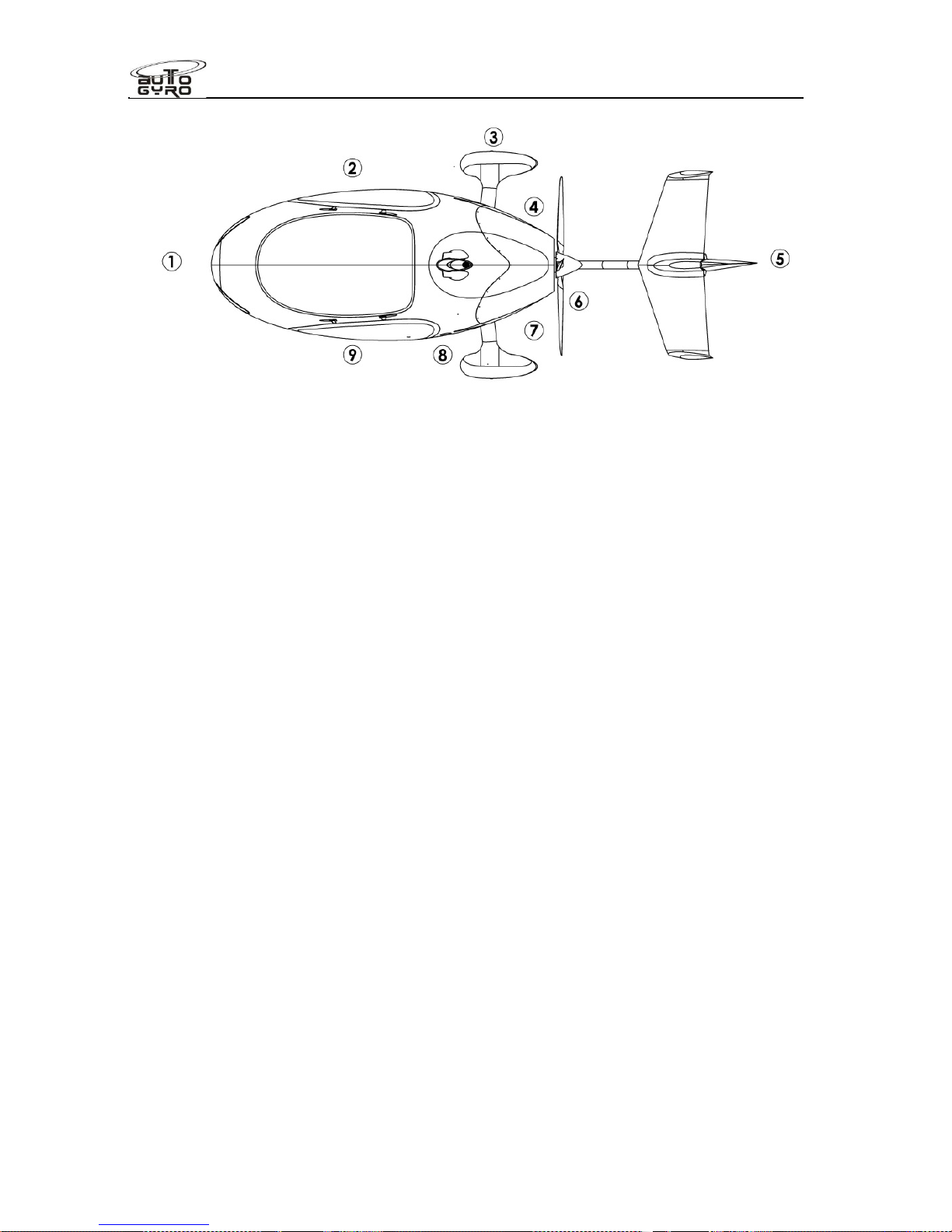
Flight Manual
Cavalon
SECTION 4
NORMAL PROCEDURES
RSUK0287_POH_Cavalon Revision 2, Issue Date 24.06.2015 4-2
The following checks must be carried out before each flight. However, if the gyroplane is
operated by a single pilot or within an organization where the checks are performed by or
under the supervision of qualified personnel, check list items marked with a preceding ‘
ʘ’
may be carried out daily, before the first flight of the day.
Before exterior check
ʘ Fuel tank drain(s)................................................................................... Sample
ʘ Snow/ ice (if any)................................................................................ Removed
Documents ............................................................................... Check complete
Exterior check
Station 1
(forward fuselage and windshield)
General appearance..................................................................................... OK
Pitot cover (if installed) ....................................................................... Removed
Pitot tube .................................................................................. Clean and open
Rotor lash bag (if sufficient brake pressure)........................................ Removed
Windshield condition and cleanliness...................................... Check, no cracks
ʘ Nose wheel condition and air pressure .................................................... Check
Station 2 (cabin, RH side)
Static port ................................................................................. Clean and open
MAG switches ................................................................................. Check OFF
Rotor brake pressure..........................................................................min. 6 bar
ʘ Throttle lever .............................................................. Check function, full travel
ʘ Brake lever and lock............................................. Check function and condition
ʘ Pedals and control cables........................................................................ Check
ʘ RH control stick bolts and nuts.............................................................. Secured
ʘ Monocoque structure condition................................................................ Check
Loose objects ........................................................................ Removed/secured
Door hinge/s..................... Quick pin installed (or nylocs/safety clips), no cracks
Door window........................................................................... Check, no cracks
Page 59

Flight Manual
Cavalon
SECTION 4
NORMAL PROCEDURES
RSUK0287_POH_Cavalon Revision 2, Issue Date 24.06.2015 4-3
Station 3 (main gear spring spar, RH)
Main wheel running surface ..................................................................... Check
Air pressure and slip mark ............................................................. Visual check
ʘ Brake, disc attachment (4 bolts) and wheel attachment............................ Check
Wheel spat and attachment ..................................................................... Check
ʘ Main gear spring spar attachment............................................................ Check
Main gear spring spar ........................................................................ No cracks
Cooling air intake .......................................................................No obstructions
Vibration decoupling element attachment (2x).......................................... Check
Gimbal head bolts (2x).............................................................Split pin installed
Rotor flight control attachments........................... No excessive play and secure
ʘ Main rotor bearing..................................................................... Check condition
ʘ Pre-rotator assembly and brake................................................ Check condition
ʘ Teeter bolt (bolt end)........................................................................ Free to turn
Teeter bolt (nut end) ................................................................Split pin installed
ʘ Teeter stops............................................................................................. Check
ʘ Rotor hub and blade clamping area ......................................................... Check
Blade attachment bolts................................................ All installed and fastened
ʘ Inner blade caps ........................................................................................ Tight
Station 4 (engine, RH side)
Open upper engine cowling
ʘ Before turning prop: MAG switches.................................................. Check OFF
ʘ Engine oil level......................................................................................... Check
ʘ Dip stick and oil cap............................................................Installed and secure
ʘ Coolant level............................................................................................ Check
Oil cooler and hoses .............................................. Clean, no leaks, fittings tight
Exhaust system ................................................................................. No cracks
Lower engine cowling ............................. Properly installed, all fasteners locked
Station 5 (stabilizer)
ʘ Stabilizer general condition...................................................................... Check
Stabilizer attachment ............................................................................... Check
Rudder control cable linkage.................................................................... Check
Upper rudder bearing................................................ Secure, no excessive play
Rotor blades condition and cleanliness.................................................... Check
Blade tips................................................................................................... Tight
Station 6 (keel tube and propeller)
ʘ Keel tube protection pad...................................................... No excessive wear
Propeller condition and cleanliness.......................................................... Check
Propeller leading edge and tips........................................................ No damage
Spinner (if installed) .................................................................. Tight, no cracks
CSP/VPP propeller (if installed) ............................................................... Check
Page 60

Flight Manual
Cavalon
SECTION 4
NORMAL PROCEDURES
RSUK0287_POH_Cavalon Revision 2, Issue Date 24.06.2015 4-4
Station 7 (engine, LH side)
ʘ Engine frame rear side / welded joints ...................... No cracks, no deformation
Oil cooler and hoses.............................................. Clean, no leaks, fittings tight
Exhaust system ..................................................................................No cracks
Lower engine cowling ............................. Properly installed, all fasteners locked
Close upper engine cowling
Station 8 (main gear spring spar, LH)
LH Main wheel running surface................................................................ Check
Air pressure and slip mark ..............................................................Visual check
ʘ Brake, disc attachment (4 bolts) and wheel attachment ........................... Check
Wheel spat and attachment ..................................................................... Check
ʘ Main gear spring spar attachment............................................................ Check
Main gear spring spar.........................................................................No cracks
Vibration decoupling element attachment (2x) ......................................... Check
Rotor flight control ...............................................No excessive play and secure
ʘ Teeter bolt (bolt end) ....................................................................... Free to turn
Teeter bolt (nut end) ................................................................ Split pin installed
Station 9 (passenger station, LH side)
ʘ LH control stick.................................................................... Secure or removed
ʘ Monocoque structure condition................................................................ Check
Seat belts ............................................................................. Fastened and tight
Door hinge/s................... Quick pin installed (or nylocks/safety clips), no cracks
Door window........................................................................... Check, no cracks
Static port ................................................................................. Clean and open
Rotor lash bag ................................................................................. As required
4.4 Before Boarding
Fuel level and fuel cap................................ Check sufficient qty and cap secure
Passenger station:
Passenger ............................................................................ Briefed and secure
Loose objects ..................................................................................... Removed
Items in storage compartment ................................................................ Secure
Seat belts ............................................................................. Fastened and tight
Door ..................................................................................... Closed and locked
Rotor brake pressure............................................ Check/set BRAKE min. 6 bar
Rotor lash bag ................................................................. Removed and stowed
Pilot station:
Loose objects ..................................................................................... Removed
Items in storage compartment ................................................................ Secure
Page 61

Flight Manual
Cavalon
SECTION 4
NORMAL PROCEDURES
RSUK0287_POH_Cavalon Revision 2, Issue Date 24.06.2015 4-5
WARNING
There is no vertical restraint provided for baggage stowed behind the occupant
seats. Normally this baggage is restrained by the vertical tapering of the
stowage area. It is the pilots responsibility to ensure any item stowed behind
the seats, or anywhere else in the aircraft, is secure. If the stowed items could
come free in the event of an accident, then suitable restraints must be fitted –
for instance, anchored to the seat belt harness lap belt mounting lugs via a
suitable strap.
4.5 Before Starting Engine
Pedals ............................................................................... Adjusted and locked
Seat belts............................................................................................ Fastened
Flight controls .............................................................................................Free
Altimeter ........................................................................ Set to airfield elevation
Doors.......................................................................... Check closed and locked
Page 62

Flight Manual
Cavalon
SECTION 4
NORMAL PROCEDURES
RSUK0287_POH_Cavalon Revision 2, Issue Date 24.06.2015 4-6
4.6 Starting Engine
Fuel shut off valve ............................................................... Open and guarded
Parking brake ............................................................................................... Set
Cold engine:
Throttle ......................................................................................................Idle
Choke....................................................................................... Fully engaged
Warm engine:
Throttle .........................................................................Idle or slightly cracked
Choke...........................................................................................Disengaged
Master switch ............................................................................................... ON
All engine variants:
Note GEN indicator light ON
Note LOW VOLT flashing briefly
ROTAX 914 engine:
Note BOOST WARN light and BOOST CAUTION light ON for about
2 seconds and buzz of electrical fuel pump.
912ULS Second fuel pump (Pump 2, to prime the fuel system) .................... ON
914UL Second fuel pump (Pump 2)……………………………………………….OFF
The 914UL pump is left OFF to prove the pump fuse and function is correct.
All engine variants: Note (increased) fuel pump buzz when Pump 2 is
turned on..
ACL / Strobe (if installed).............................................................................. ON
Both MAG switches ...................................................................................... ON
Propeller and area...................................................................................“Clear”
Starter (with right hand, left hand on throttle/brake) ............................... Engage
Hold starter until engine fires, but for a maximum of 10 seconds. Generally
the engine fires immediately. In case of an unsuccessful starting attempt
check all preconditions. Wait at least 20 seconds to allow cooling of battery
and starter motor before repeated activation.
Oil pressure.....................................................................................min. 1.5 bar
Second fuel pump (Pump 2) ...................................................................... OFF
Avionics/Radio/Intercom............................................................................... ON
Choke......................................................................................slowly disengage
WARNING
Never attempt to start the engine until the area around the propeller is
completely clear of any persons or objects.
Page 63

Flight Manual
Cavalon
SECTION 4
NORMAL PROCEDURES
RSUK0287_POH_Cavalon Revision 2, Issue Date 24.06.2015 4-7
4.7 Taxi and Run-up
During taxi do not exceed 15 km/h (10mph) which is approximately jogging speed and steer
with careful pedal input. Use wheel brake carefully, if needed, but not before throttle lever
has been completely pulled to idle. Control stick should always be maintained in forward
centre position. When taxiing on uneven ground, use particular caution and hold control
stick so as to avoid the blades or control system hitting their mechanical stops.
Carry out engine run-up in an area with least risk to individuals and other airport ground
traffic, preferably headed into the wind.
Warm-up RPM.......................................................................2000 – 2500 RPM
Oil temperature and other engine indications ................................... within limits
At taxi holding position:
Magneto check (at 4000 RPM)............................................ max. 300 RPM drop
with max. difference between magnetos .......................................... 115 RPM
Switch ignition/magnetos with right hand while left hand resides on
throttle/brake.
Throttle ........................................................................................................ Idle
Warning and caution indications ................................................................None
Instruments / altimeter ....................................................................Cross check
NAV lights........................................................................................ As required
Second fuel pump (Pump 2) .........................................................................ON
Doors................................................................ Cross-check closed and locked
Approach and runway......................................................... “Clear”, then line-up
4.8 Take-off Procedure
Check relative wind
Maintain control stick in forward position with right hand
Switch pneumatic mode selector to FLIGHT and return to brake with left hand
Hold wheel brake without having locking pawl engaged
While holding wheel brake adjust 2000 RPM with throttle Activate and hold pre-
rotator
Let pneumatic clutch fully engage (stabilization at about 110 rotor RPM).
If necessary release pre-rotator button momentarily and press again to maintain
engine RPM within green arc, and prevent engine from stalling!
Carefully increase throttle (~ 20 R-RPM/sec) to 200 R-RPM – max. 220 R-RPM
Release pre-rotator button
Gently move control stick fully aft (stick travel ~ 1 sec.).
In a strong headwind be prepared to stop movement before nose wheel rises!
Release wheel brake with throttle unchanged
Monitor rotor speed and adequately increase throttle to take-off power
Page 64

Flight Manual
Cavalon
SECTION 4
NORMAL PROCEDURES
RSUK0287_POH_Cavalon Revision 2, Issue Date 24.06.2015 4-8
WARNING
Before activating the pre-rotator, check area is clear.
WARNING
Prior to releasing the wheel brake, make sure that the control stick is fully aft, if
headwind component allows. A take-off run with flat rotor system may have
fatal consequences.
WARNING
With the rotor speed below green arc relative speed must be built-up carefully
to allow rotor speed to increase first. If the situation cannot be corrected, abort
take-off run.
CAUTION
Do not engage pre-rotator at too high engine RPM or until too high rotor RPM
as this will lead to pre-rotator drive damage.
CAUTION
Avoid overtorqing of the pre-rotator drive! Overtorqing will occur if RPM/power
is fed excessively or abruptly. In case of a stalling engine, release pre-rotator
button temporarily. Do not yank the throttle control while the clutch is engaged!
NOTE
Perform take-off into the wind and with least possible crosswind component.
NOTE
To avoid unintended engagement in flight the pre-rotator can only be activated
with the control stick in its most forward position.
Page 65

Flight Manual
Cavalon
SECTION 4
NORMAL PROCEDURES
RSUK0287_POH_Cavalon Revision 2, Issue Date 24.06.2015 4-9
WARNING
In the event of pre-rotator failure, STOP and rectify the fault. Do NOT attempt to
pre-spin by hand, as this involves considerable personal risk if the engine is
running.
4.9 Take-off Run
Check full power available for take-off. Otherwise, abort take-off
Minimize lateral drift by applying appropriate lateral control stick input into cross wind
direction
Maintain directional control i.e. runway alignment with sensitive pedal input
When nose comes up allow nose wheel to float at about 10 – 15 cm above the
runway by a balanced reduction of control stick back pressure
Maintain attitude until speed increases and gyroplane lifts off (at around 50mph)
Allow gyroplane to build-up speed in ground effect
WARNING
Gyroplanes are fully controllable at very low speeds without exhibiting any
signs of wing stall or soft flight controls, as would be the case in a fixed wing
aircraft. However, operation ‘behind the power curve’ may have fatal
consequences during take-off, initial climb or in any other situation within
close ground proximity. Always allow aircraft to build-up safe climb speed
before allowing it to gain height.
4.10 Climb
Perform initial climb at safe climb speed and adjust trim
Set power to maximum take-off power
Check engine instruments and respect maximum take-off power time limit
Switch off second fuel pump at safe height
At safe altitude, the climb may be continued with VYand reduced power setting for
noise abatement
When desired altitude is approached, level gyroplane and reduce power
4.11 Cruise
Adjust power setting within the maximum continuous power range
Adjust trim
4.12 Descent
Reduce power setting and lower nose
Adjust trim
Page 66

Flight Manual
Cavalon
SECTION 4
NORMAL PROCEDURES
RSUK0287_POH_Cavalon Revision 2, Issue Date 24.06.2015 4-10
4.13 Approach
Switch ON second fuel pump (Pump 2)
Check all warning and caution indications OFF
Check all instruments in normal operating range
Check wheel brake unlocked
Maintain and trim approach speed
Control glide angle with engine power
WARNING
An approach within the gliding distance to the airport or landing site is
generally considered to be the safest option.
4.14 Landing
Align gyroplane with rudder and correct drift with lateral control input, even if this
results in a side slip indication
Maintain approach speed until approximately 5m above runway
Manage the throttle to maintain the desired approach speed, reducing the throttle to
closed (or other appropriate power setting for the conditions) in preparation for the
flare.
Initiate round out to reduce sink rate and let ground approach
Perform final flare close to ground as speed will decay rapidly
Let gyroplane settle on main gear with nose wheel slightly above the ground
Hold nose wheel closely above ground and let it sit down with pedals neutral at the
lowest possible ground speed, reducing/closing the throttle as required.
Maintain aft control stick to reduce speed until walking speed. Wheel brake may be
used to assist, if needed
CAUTION
When landing in a strong headwind do not use wheel brake to prevent
gyroplane from rollback. In order to compensate for any rollback tendency,
flatten rotor disc as required and increase propeller thrust as required.
CAUTION
Touching down with the nosewheel pointing left or right, and with a run-on
speed, will cause the wheel to ‘grab’ in that direction. If left uncorrected the
aircraft will try to turn in that direction, possibly resulting in a roll-over. Always
lower the nose at low ground speed, with the nosewheel straight.
Page 67

Flight Manual
Cavalon
SECTION 4
NORMAL PROCEDURES
RSUK0287_POH_Cavalon Revision 2, Issue Date 24.06.2015 4-11
4.15 Go-around
Apply take-off power. Counteract yaw tendency and align gyroplane with rudder input
In horizontal flight, allow gyroplane to gain speed
Climb with safe or best rate of climb speed and adjust trim
.
4.16 After Landing
Control stick full forward to level-off rotor disc, at latest when rotor speed leaves
green arc! Be prepared for reduced rotor drag!
Use lateral control into wind to maintain rotor disc in level attitude. Adjust lateral
control input as rotor speed decays
Bring pneumatic mode selector to BRAKE position and return to wheel brake with left
hand
Apply rotor brake pressure by using AFT TRIM. Monitor pressure gauge
Taxi carefully, preferably not above walking speed and mind high centre of gravity
when taking turns
Do not vacate gyroplane until engine and rotor is at a complete stop
WARNING
Mind the spinning rotor and propeller when taxiing close to obstructions or
persons. A fast turning rotor is almost invisible, but may contain enough
energy to kill a person.
CAUTION
Try to park the blades fore/aft of the aircraft, to avoid high stick loads in roll
when taxying. Depress the pre rotator interlock release button & engage the
pre-rotator to wind the rotor into the desired position. The use of abrupt pedal
inputs to do this during taxiing should be avoided.
NOTE
It is advisable to let the rotor spin down while the gyroplane is at a complete
stop. However, in order to vacate the runway, it is possible to taxi while the
rotor is spinning down. In this case, be aware of the effects of relative wind on
advancing and retreating blade, compensate with lateral control input, and
adjust taxi speed carefully as to avoid blade flapping.
Page 68

Flight Manual
Cavalon
SECTION 4
NORMAL PROCEDURES
RSUK0287_POH_Cavalon Revision 2, Issue Date 24.06.2015 4-12
4.17 Engine Shut-down
Throttle.........................................................................................................Idle
Parking brake ............................................................................................... Set
Turbo charger cool-down (ROTAX 914 engine) ................................ min. 2mins
Second fuel pump (Pump 2) ...................................................................... OFF
Avionics/Radio/Intercom/Lights (except ACL / Strobe)................................ OFF
Both MAG switches .................................................................................... OFF
ACL / Strobe (if installed)............................................................................ OFF
Master switch ................................................................. OFF and key removed
4.18 Parking
Install rotor tie-down bag
Secure gyroplane against rolling using parking brake and chocks, if parked on a
slope
Double check to have master switched OFF and keys removed
Install protection cover if available or appropriate
NOTE
Avoid long term parking of the aircraft with empty tanks. This will increase the
risk of water accumulation in the tanks and will lead to shrinking of the rubber
tank seal.
4.19 Special Procedure: Short Field Take-off
A short field take off is conducted in exactly the same manner as a normal take-off, but
performed with maximum precision. Therefore, a short field take-off is not so much a
procedural thing, but needs practice, experience and mentoring. Apart from environmental
aspects such as wind and density altitude, the condition of the gyroplane and its gross
weight, the key factors for a short take-off performance are:
Maximum allowed pre-rotation RPM and no time lost until stick is fully aft (if headwind
component allows) and brake is released
Maximum take-off power is set immediately while stick remains fully aft until nose
wheel rises
Nose wheel held just above the ground with minimum side drift until lift-off
No over controlling that would result in the nose swinging up and down
VYclimb with no side slip
4.20 Special Procedure: Slow Speed Sink and Recovery
Reduce power to idle and let speed decrease by gently using aft control stick
Maintain enough forward speed for the rudder to remain effective
Rudder will regain effectiveness quickly as soon as airspeed or propeller thrust is
increased
To recover, let nose drop slightly below the horizon and build-up air speed while
adding power at the same time
Page 69
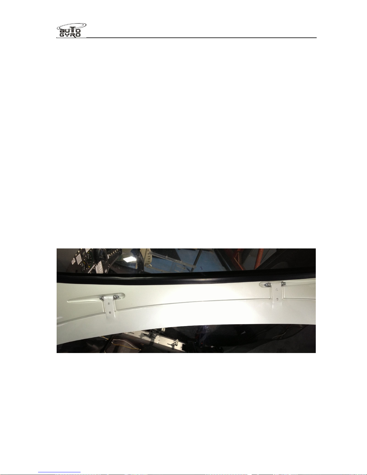
Flight Manual
Cavalon
SECTION 4
NORMAL PROCEDURES
RSUK0287_POH_Cavalon Revision 2, Issue Date 24.06.2015 4-13
4.21 Flight with Doors Removed
Before flying with removed doors any loose objects must be removed from the cabin or
safely stowed.
A possible tail shake (fishtailing) tendency can be minimized by using a small side slip. In
case where only one door is removed, perform a small side slip into the direction of the
closed door (so that the removed door is on the lee-side).
Door removal is a permissible pilot activity.
1. Take care not to damage the paint! A cautionary approach is to fit some lengths
of masking tape around the hinge area to prevent tool damage, or chips from
fitting slippage.
2. Remove gas strut from door to be removed by popping the ends from the nipple
on the door and on the aircraft body.
3. Close the door and loosely lock.
4. Noting the location and quantity of washers, remove the nut and hinge bolt (or
quik pins, where fitted) from both hinges. Alternatively, remove the 4 bungs on
the inside of the cabin, and remove the 4 nuts that hold the hinge eye bolts in
place with a socket drive.
5. Disengage the door lock, and lift the door away from the aircraft – and put it onto
a suitable protected surface.
6. Remove ALL loose articles rom the cabin, including dirt that could get blown
around and over the occupants.
7. Note the removal in the aircraft logbook.
View of the two door hinges. Note direction of bolt fitment.
1. Take care not to damage the paint! A cautionary approach is to fit some lengths of
masking tape around the hinge area to prevent tool damage, or chips from fitting
slippage
2. Reverse items 2. To 6., and note refitment in aircraft logbook. Replace nylocks as
required
Page 70

Flight Manual
Cavalon
SECTION 4
NORMAL PROCEDURES
RSUK0287_POH_Cavalon Revision 2, Issue Date 24.06.2015 4-14
4.22 Training Engine In-flight Shut-down and Air Restart
The engine should not be stopped in flight deliberately except as part of forced landing
training under the supervision of a qualified flight instructor. If possible, allow the engine to
cool down at 3000 rpm for about 30 sec before turning it off.
Make sure both magnetos are switched back ON and the master switch/starter key has
been turned to OFF and back to ON to be prepared for an immediate engine start-up in
case the manoeuvre has to be aborted.
NOTE
Be aware of reduced rudder effectivity (and increased drag) with a stationary
propeller. Be prepared to use larger pedal input and more left pedal than usual
to keep gyroplane aligned.
After a restart, allow engine and oil to warm-up, if possible, before full power is applied.
4.23 Noise Abatement
A positive attitude towards residents and environmental-friendly flying supports the
reputation and acceptance of aviation in general, and gyroplanes in particular. When
compared to other aeroplanes the noise of a gyroplane is sometimes perceived as
unpleasant although it meets the same or sometimes more stringent noise emission
requirements. This effect can be attributed to the pusher concept where the propeller is
exposed to air flow which was distorted by the fuselage. The degree of distortion, and
therefore the noise emission of the propeller, is significantly lower at reduced speeds. The
best practices to keep noise level low and general acceptance high are:
Climb with the speed for best rate of climb VYas soon as altitude permits
Especially in climb keep side slip to a minimum to establish a clean configuration.
In addition, this guarantees the best climb performance
For your own safety always maintain safe altitude and avoid unnecessary ‘low-
flying’
When overflying populated areas, look ahead and select the least noise sensitive
route
Repetitive noise is far more irritating than a single occurrence. If you must fly over
the same area more than once, vary your flight path
Avoid blade slap. Blade slap can occur as a result of inadequate piloting
technique or during aggressive manoeuvres, but will not appear in normal flight
regime
NOTE
Above procedures do not apply where they would conflict with Air Traffic
Control, within the traffic pattern, or when, according to pilot’s judgement, they
would result in an unsafe flight path.
Page 71

Flight Manual
Cavalon
SECTION 4
NORMAL PROCEDURES
RSUK0287_POH_Cavalon Revision 2, Issue Date 24.06.2015 4-15
INTENTIONALLY LEFT BLANK
Page 72

Page 73

Flight Manual
Cavalon
SECTION 5
PERFORMANCE
RSUK0287_POH_Cavalon Revision 2, Issue Date 24.06.2015 5 - i
CONTENTS
5.1 Demonstrated Operating Temperature ..........................................................5-1
5.2 Airspeed Correction....................................................................................... 5-1
5.3 Height-Velocity Diagram................................................................................ 5-2
5.4 Speeds.......................................................................................................... 5-3
5.5 Rate of Climb................................................................................................. 5-3
5.6 Take-off and Landing Data ............................................................................5-3
5.7 Influence on Take-off Distance and Climb Rate .............................................5-4
5.8 Sink Rate and Glide Ratio .............................................................................5-6
5.9 Additional Performance Data.........................................................................5-6
5.9.1 Fuel Flow..................................................................................................5-6
5.9.2 Service Ceiling.......................................................................................... 5-6
5.10 Sound Exposure Level / Noise Characteristics ..............................................5-6
Page 74

Flight Manual
Cavalon
SECTION 5
PERFORMANCE
RSUK0287_POH_Cavalon Revision 2, Issue Date 24.06.2015 5 - ii
INTENTIONALLY LEFT BLANK
Page 75
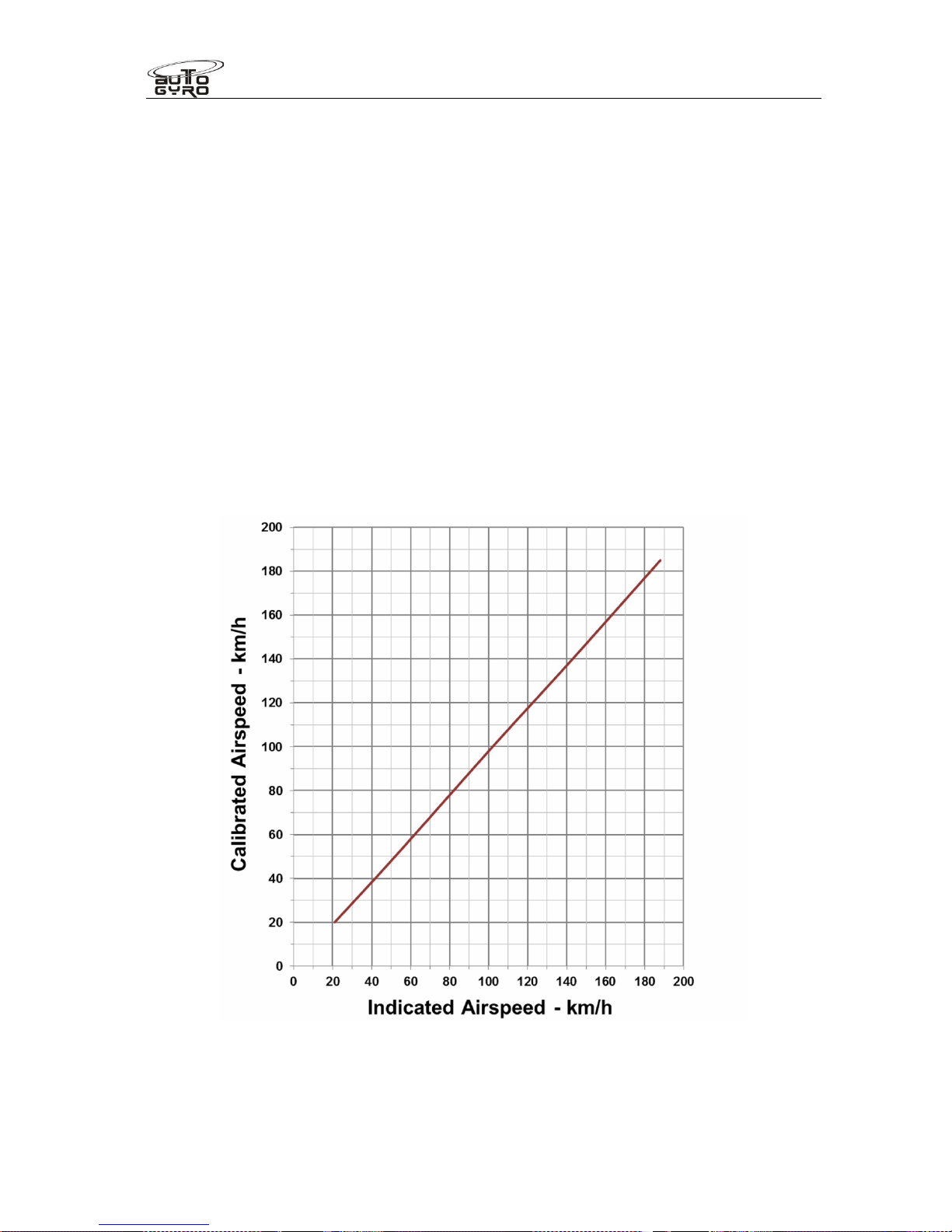
Flight Manual
Cavalon
SECTION 5
PERFORMANCE
RSUK0287_POH_Cavalon Revision 2, Issue Date 24.06.2015 5-1
PERFORMANCE
SECTION 5 -
The following data were determined by flight testing and demonstrated with average piloting
skills, with engine and aircraft in good condition, as well as clean main rotor and propeller.
The parameters apply to standard conditions (15 °C at sea level and standard pressure)
and a gross mass of 500 kg. Note that operation at 560kg MTOW, a higher airfield
elevation, increased temperature and low air pressure will have a negative effect on
performance.
5.1 Demonstrated Operating Temperature
Satisfactory engine cooling has been demonstrated at outside air temperatures up to 40 °C.
5.2 Airspeed Correction
Example: Indicated airspeed of 140 km/h represents a calibrated airspeed (corrected for
installation error) of 138 km/h.
Page 76
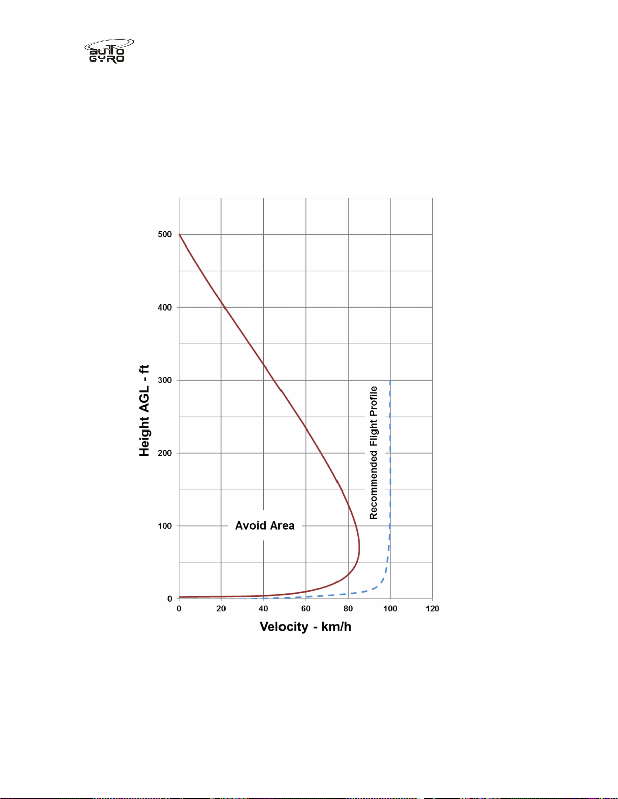
Flight Manual
Cavalon
SECTION 5
PERFORMANCE
RSUK0287_POH_Cavalon Revision 2, Issue Date 24.06.2015 5-2
5.3 Height-Velocity Diagram
The H/V diagram indicates combinations of height and speed (avoid area left side of the red
graph) where a safe landing may not be possible in case of an engine failure. Therefore,
operation on the left side of the red line must be avoided.
Take-offs and landings should be conducted according to the recommended flight profile,
provided as blue dashed line.
0 25 37 50 62 75
Velocity - mph
Page 77

Flight Manual
Cavalon
SECTION 5
PERFORMANCE
RSUK0287_POH_Cavalon Revision 2, Issue Date 24.06.2015 5-3
5.4 Speeds
The following speeds are relevant for flight performance. For additional speed limitations
refer to SECTION 2 LIMITATIONS of this manual.
Mini horizontal speed (Vmin), TOP (Rotax 914)*, 500Kg... 48 km/h (30mph) IAS
Vmin, TOP (Rotax 914)* 560KgTOW ................................61 km/h (38mph) IAS
Vmin, TOP (Rotax 914)* 560Kg, IVO prop ........................56 km/h (35mph) IAS
Minimum horizontal speed, (Vmin) TOP (Rotax 912) ........56 km/h (35mph) IAS
Speed for best angle of climb V
X
.....................................100 km/h (60mph) IAS
Speed for best rate of climb or maximum endurance V
Y
..102 km/h (70mph) IAS
Best range speed.............................................................110 km/h (70mph)IAS
Long range speed** ........................................................ 120 km/h (75mph) IAS
Approach speed***.......................................................... 100 km/h (60mph) IAS
Vmc power-off**** ............................................................. 32 km/h (20mph) IAS
Vmc power on**** ...............................................................0 km/h (00mph) IAS
* Take care! A full power operation at Vmin with a Rotax 914UL will result In a
very high nose-up attitude with little forward visibility.
** Long range speed is the speed faster than the best range speed which
results in a slightly lesser range but represents a good compromise between
range and saved air time.
*** Approach speed above 60mph builds energy in the rotor that results in a
long floating landing. Approach speed at 50mph results in a very short
landing roll, and below 50mph requires increasing skill especially at
maxTOW.
****Vmc is the minimum controllability speed. At 20mph or below, engine off,
rudder authority reduces, to negligible below 10mph.
5.5 Rate of Climb
Rate of climb, 500 kg, VY, TOP, 914UL................................... 3.8 m/s (750fpm)
Rate of climb, 560 kg, V
Y
, TOP, 914UL................................... 2.8 m/s (550fpm)
Rate of climb, 500 kg, V
Y
, TOP, 912ULS................................. 2.5 m/s (500fpm)
5.6 Take-off and Landing Data
Take-offs and landings have been demonstrated up to a crosswind component of 36 km/h
(22mph).
The following data is valid for operation at a gross mass of 500 kg and 560Kg where shown
at an even air strip with short grass, no wind, and pre-rotation to 220 RPM (or 200rrpm for
560Kg pre rotation). Take-off and landing distances account for a 15m obstacle.
Wet grass or boggy conditions will significantly increase this.
Take-off roll* .................................................................................... 80 – 200 m
Take-off distance, 914UL to clear a 15m obstacle.................................... 405 m
Page 78
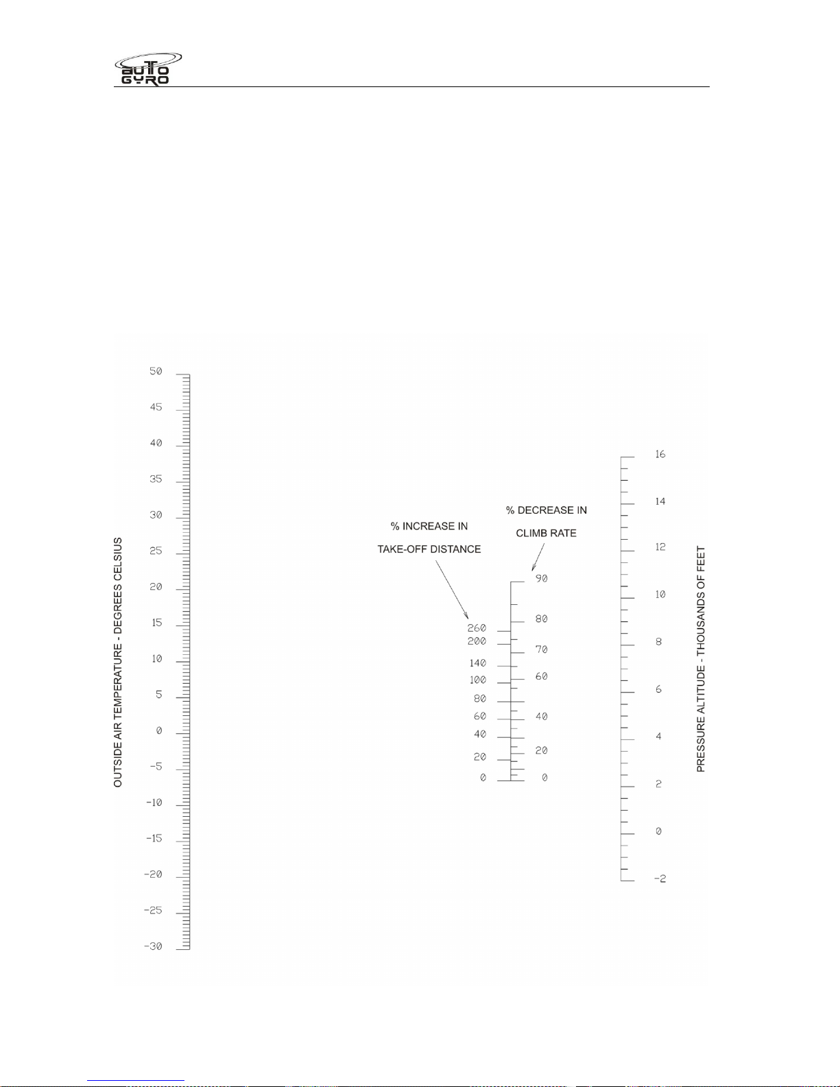
Flight Manual
Cavalon
SECTION 5
PERFORMANCE
RSUK0287_POH_Cavalon Revision 2, Issue Date 24.06.2015 5-4
T/off distance, 914UL to clear a 15m obstacle at 560Kg MTOW ...............780 m
T/off distance, 914UL to clear a 15m obstacle at 560Kg MTOW, Ivoprop..590 m
Take-off distance, 912ULS to clear a 15m obstacle ..................................550 m
Landing roll...........................................................................................0 – 20 m
Landing distance over a 15m obstacle......................................................150 m
5.7 Influence on Take-off Distance and Climb Rate
All flight performance figures presented in this chapter are based on standard atmospheric
conditions in sea level. Depending on actual temperature and pressure altitude (elevation)
factors on take-off distance and climb rate can be deducted from the following chart.
See next page for example.
Page 79
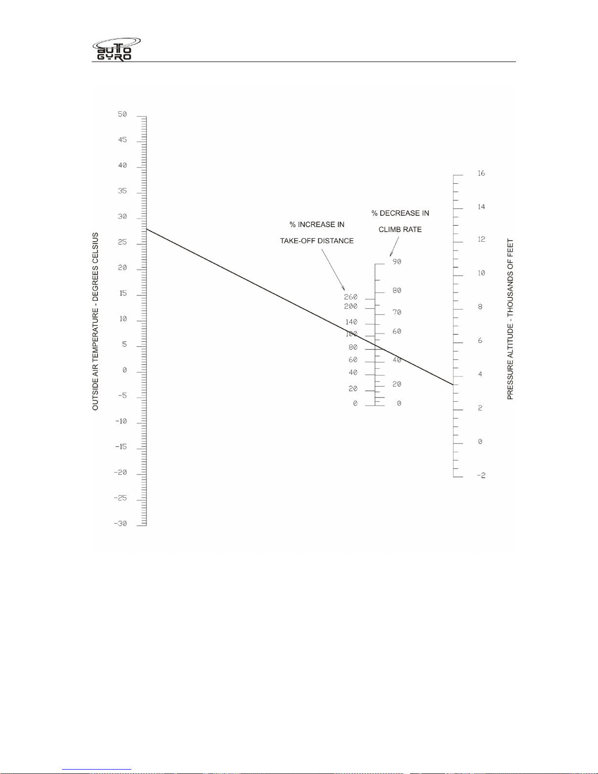
Flight Manual
Cavalon
SECTION 5
PERFORMANCE
RSUK0287_POH_Cavalon Revision 2, Issue Date 24.06.2015 5-5
Example:
Given: Outside Air Temperature 28 °C and Pressure Altitude 3500 ft
Result: 88 % increase in take-off distance and climb rate reduced by 53 %
Page 80
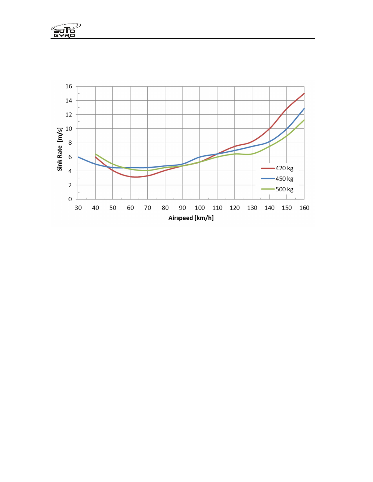
Flight Manual
Cavalon
SECTION 5
PERFORMANCE
RSUK0287_POH_Cavalon Revision 2, Issue Date 24.06.2015 5-6
5.8 Sink Rate and Glide Ratio
The sink rate depending on airspeed with the engine in idle is plotted in the following
diagram:
At 560Kg MTOW expect a sink rate of 1050fpm at 35KIAS, 1200 at 43KIAS, 1120 at
52KIAS, 1320 at 61KIAS, 1550 at 70KIAS, and 1600 at 78KIAS.
In case of an engine failure, expect a glide ratio of 1:3 which corresponds to a vertical
distance of 900 m or 0.5 nautical miles for each 1000 ft.
5.9 Additional Performance Data
5.9.1 Fuel Flow
The following fuel flow figures are provided as estimates and do not constitute certified
performance. Exact fuel flow will vary with environmental conditions, cleanliness of propeller
and rotor, piloting technique (minimum side slip), and power setting. For additional
procedures about proper power setting consult SECTION 9 for supplemental data
concerning the variable pitch propeller, if installed.
Fuel flow at 125 km/h (78mph) IAS..........................................................15 ltr/h
Fuel flow at 140 km/h (87mph) IAS..........................................................18 ltr/h
5.9.2 Service Ceiling
See SECTION 2 LIMITATIONS
5.10 Sound Exposure Level / Noise Characteristics
Page 81

Flight Manual
Cavalon
SECTION 5
PERFORMANCE
RSUK0287_POH_Cavalon Revision 2, Issue Date 24.06.2015 5-7
The noise certificate was granted according to the German requirements for noise
protection for microlight gyroplanes (“Lärmschutzverordnung für Ultraleichte
Tragschrauber”) stating an overfly noise of 68 dB or less.
Page 82

Page 83

Flight Manual
Cavalon
SECTION 6
WEIGHT AND BALANCE
RSUK0287_POH_Cavalon Revision 2, Issue Date 24.06.2015 6 - i
CONTENTS
6.1 General ......................................................................................................... 6-1
6.2 Weight and Balance Record .......................................................................... 6-1
6.3 Compliance with Weight and Balance............................................................ 6-1
Page 84

Flight Manual
Cavalon
SECTION 6
WEIGHT AND BALANCE
RSUK0287_POH_Cavalon Revision 2, Issue Date 24.06.2015 6 - ii
INTENTIONALLY LEFT BLANK
Page 85

Flight Manual
Cavalon
SECTION 6
WEIGHT AND BALANCE
RSUK0287_POH_Cavalon Revision 2, Issue Date 24.06.2015 6-1
WEIGHT AND BALANCE
SECTION 6 -
6.1 General
The gyroplane must be operated within the weight and balance limits as specified in
SECTION 2 of this manual. Loading situations outside these limits can result in restricted
flight control and can ultimately lead to degraded safety.
6.2 Weight and Balance Record
An initial weighing report and equipment list showing gyroplane configuration, empty weight
and centre of gravity is delivered with each gyroplane. This data applies to the gyroplane as
delivered from RotorSport UK Ltd. Any changes in the configuration should be performed by
a qualified maintenance station and documented. After modifications and at regular
intervals a new weighing report and equipment list should be issued.
6.3 Compliance with Weight and Balance
The Cavalon gyroplane is designed in such way that compliance with weight and balance is
provided, if
the gyroplane is loaded within the individual weight limitations for each station as
provided in SECTION 2 of this manual, and
the maximum allowable cockpit loading (both seats and baggage) is respected,
and
the approved maximum take-off weight, representing the total sum of pilot,
passenger, baggage, fuel and current empty weight is not exceeded
Page 86

Flight Manual
Cavalon
SECTION 6
WEIGHT AND BALANCE
RSUK0287_POH_Cavalon Revision 2, Issue Date 24.06.2015 6-2
INTENTIONALLY LEFT BLANK
Page 87

Flight Manual
Cavalon
SECTION 7
SYSTEM DESCRIPTION
RSUK0287_POH_Cavalon Revision 2, Issue Date 24.06.2015 7 - i
CONTENTS
7.1 Introduction.................................................................................................... 7-1
7.2 Airframe and Undercarriage........................................................................... 7-1
7.3 Doors, Windows and Exits.............................................................................7-1
7.4 Fuel System .................................................................................................. 7-1
7.5 Pneumatic System.........................................................................................7-3
7.6 Power Plant................................................................................................... 7-4
7.7 Propeller........................................................................................................ 7-4
7.8 Rotor System................................................................................................. 7-4
7.9 Vibration Damping......................................................................................... 7-5
7.10 Flight Controls ............................................................................................... 7-5
7.11 Electrical System........................................................................................... 7-8
7.12 Lighting System............................................................................................. 7-9
7.13 Electrical fusing .............................................................................................7-9
7.14 Avionics....................................................................................................... 7-11
7.15 Instrument Panel ......................................................................................... 7-12
7.16 Intercom ...................................................................................................... 7-14
7.17 Pitot Static ................................................................................................... 7-14
7.18 Indicators and Sensors................................................................................ 7-14
7.19 Seats and Seatbelts .................................................................................... 7-14
7.20 Stowage Capacity........................................................................................ 7-14
Page 88

Flight Manual
Cavalon
SECTION 7
SYSTEM DESCRIPTION
RSUK0287_POH_Cavalon Revision 2, Issue Date 24.06.2015 7 - ii
INTENTIONALLY LEFT BLANK
Page 89
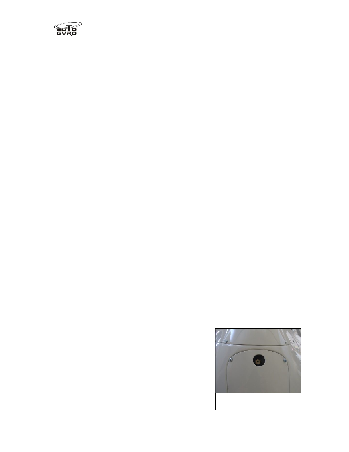
Flight Manual
Cavalon
SECTION 7
SYSTEM DESCRIPTION
RSUK0287_POH_Cavalon Revision 3., Issue Date 06.04.16 7-1
SYSTEM DESCRIPTION
SECTION 7 -
7.1 Introduction
This section contains the description of the gyroplane and its standard systems and
equipment. Optional equipment is described in Chapter 9 of this manual.
7.2 Airframe and Undercarriage
The load carrying structure of the gyroplane consists of a composite monocoque occupant
enclosure which is connected to the rotor tower and keel tube. The composite structure,
tower and aft extension carries all loads induced by the crew stations, engine, rotor,
undercarriage, stabilizer, and serves as installation platform for additional equipment.
Stabilizer structure with rudder is made of GRP (or in certain cases CRP) and is bolted to
the aft extension of the main frame. Attachment points for the engine installation are
provided by a steel tube ring mount at the rear of the firewall.
The landing gear consists of a steerable nose wheel in a steel fork and two main wheels
with hydraulic brake system. Both main wheels are equipped with wheel spats made from
GRP and are mounted to the ends of the spring spar, which is made from GRP. The spar is
designed to absorb even higher than normal landing loads in case of a hard landing or
crash.
7.3 Doors, Windows and Exits
This gyroplane features one large undivided glazed canopy and two hinged doors with
locking mechanism at the left hand and right hand side. The locking mechanism can be
operated from the inside and outside by moving an aluminium locking lever. The door is
properly locked when the lever jumps sidewise into its locking detent.
Two adjustable fresh air vents one on each side and one sliding window per side with
pivoting vent are provided for ventilation. The sliding window can be used as viewing hatch
in case of emergencies and is wide enough to reach through with a hand.
The gyroplane is embarked and disembarked from each side while the doors are held open
by a gas spring. In case of emergency the opposite door may have to be used to disembark
the aircraft.
7.4 Fuel System
The fuel system consists of two tanks permanently
connected with a large bore crossover tube allowing
them to be considered as one large tank, with a single
filler port, fuel and ventilation lines, fuel level indicator,
and water drain point. The filler port is located at the
left hand side of the gyroplane. In order to open the
filler cap, lift, then turn the flap, and pull out. Reverse to
close cap. The cap is retained to the aircraft via a
security cable.
The tanks are installed behind the seats and have a
capacity of 100 usable litres. Fuel level can be checked
Under body water drain
Valve
Page 90
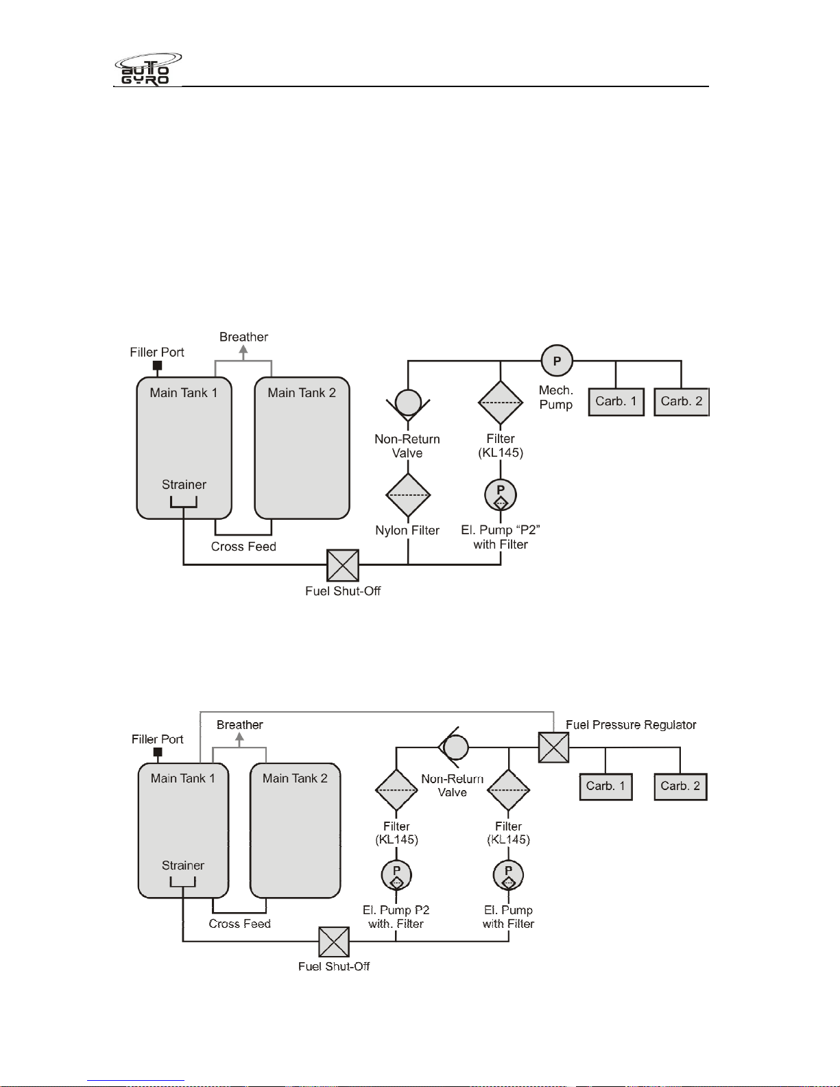
Flight Manual
Cavalon
SECTION 7
SYSTEM DESCRIPTION
RSUK0287_POH_Cavalon Revision 3., Issue Date 06.04.16 7-2
visually using a dip stick (stored in the cabin) which has to be inserted diagonally from the
fuel filler port (see 8.5).
The tanks are ventilated by a ventilation line above the tanks leading through the
midchannel directly to the outside.
As an option, a low fuel sensor may be installed. The LOW FUEL warning light is triggered
as soon as 5 litres or less of useable fuel remain in the tank.
The fuel system versions differ with engine model, see schematics below.
Fuel system ROTAX 912:
Fuel system ROTAX 914:
Page 91

Flight Manual
Cavalon
SECTION 7
SYSTEM DESCRIPTION
RSUK0287_POH_Cavalon Revision 3., Issue Date 06.04.16 7-3
7.5 Pneumatic System
Aircraft trim, rotor brake and activation of the pre-rotator is controlled by a pneumatic
system, consisting of an electrically driven air compressor with dry cartridge, a pressure
gauge in the cockpit, solenoid valves, air lines, pneumatic actuators, and the respective
cockpit controls.
Trim function
Trimming is effected by varying trim pressure in the pneumatic trim actuator which is
installed in parallel with the rotor head tilt for pitch control. Aft or nose-up trimming activates
the electrical compressor and increases trim pressure, causing the actuator to retract, and
tilting the rotor disc aft. Forward trimming opens the pressure relief valve to reduce trim
pressure and allows the rotor disc to flatten, due to the spindle head offset and the
gyroplane’s weight. The actual trim condition is indicated on the trim/brake pressure gauge
in the centre panel of the cockpit.
Lateral/roll trim works similarly, using a lateral pneumatic trim cylinder. Lateral trim condition
is indicated by a LED bar on the instrument panel.
Rotor brake
With the pneumatic mode selector in BRAKE position the operation of the pneumatic trim
actuator is reversed so that increased pressure causes the actuator to push the rotor head
up (or level) and presses a brake pad against the rotor head disc. In order to increase brake
pressure, move the 4-way trim switch on the stick grip aft. Note that this action will also
push the control stick forward. At full brake pressure the control stick will be maintained in
its full forward position.
Activation of the pre-rotator
The pre-rotator is activated when the button on the control stick grip is depressed provided
the following pre-conditions are met:
pneumatic mode selector set to FLIGHT
control stick in full forward position
rotor brake pressure less than 3 bar
When activated the pneumatic clutch is engaged and engine torque is transmitted through a
90° gearbox and drive to the pinion which is engaged by another small pneumatic actuator
into the geared ring of the rotor head. The drive pinion is sliding on a helical gear to provide
automatic lock-out in case of rotor RPM overrun. The pre rotator drives shafts feature sliding
splined elements to accommodate drive shafts length changes due to rotor head and
engine operational movement.
Activation of the pre-rotator in BRAKE position
The pre-rotator can be activated in BRAKE position to park the rotor blades fore-aft for taxi.
To do so, the pre-rotator switch and the overdrive/override switch in the cockpit panel have
to be pressed simultaneously. Avoid prolonged activation of the pre-rotator with rotor brake
engaged.
Page 92

Flight Manual
Cavalon
SECTION 7
SYSTEM DESCRIPTION
RSUK0287_POH_Cavalon Revision 3., Issue Date 06.04.16 7-4
7.6 Power Plant
Engine
There are two engine variants available, being the ROTAX 912 ULS normally aspirated
reciprocating engine and the ROTAX 914 UL turbo charged version. Both engine types are
4 cylinder, horizontally opposed, 4 stroke engines.
The ROTAX 912 ULS engine provides a maximum take-off power of 100 horse power while
the turbo charged version offers a maximum take-off power of 115 horse power. For
technical details refer to the engine manufacturer’s manual.
Oil system
The oil reservoir with dipstick is accessed through a cover on the left hand side of the
fuselage. The cover is held by 3 cam lock fasteners which can be locked or unlocked by a
quarter turn. The type of lubrication system requires a special procedure for accurate oil
level checking and to prevent overfilling, which is described in SECTION 8 of this manual.
Engine cooling
Engine cooling is provided by ram air cooled cylinders and liquid cooled cylinder heads.
Therefore, cylinder head temperature (CHT) indication in the cockpit corresponds to water
temperature. Sufficient cooling air flow is provided by a ram air duct. The water cooling
system comprises of engine driven pump, radiator with thermo-activated electrical blower
fan, expansion tank with radiator cap, overflow bottle, and hoses.
A single, large area radiator is mounted above the engine so that cooling air from the ram
air duct passes through the cooler, is directed around the engine’s cylinders, and finally
escapes through an opening at the lower rear end of the engine cowling. Force cooling is
ensured by an electrically driven ducted fan controlled by a thermo switch. A push button in
the cockpit allows manual activation temporarily which is typically used to avoid possible
heat build-up after shut-down.
In order to support natural heat circulation (chimney effect) the blower fan reverses in
ground mode to allow the hot air escape at the ram air opening in the forward mast cover.
Ground mode is detected when the engine is off.
For the relevant checking and replenishing procedures, refer to SECTION 8 of this manual
and also the engine manufacturer’s manual.
7.7 Propeller
A three-bladed, fixed pitch propeller with aluminium hub is used as standard version. The
propeller blades are made from composite material with a foam core.
7.8 Rotor System
The two-bladed, semi-rigid, teetering rotor system comprises high-strength aluminium
extruded rotor blades, a hub bar, and a common teeter hinge assembly.
The rotor blades feature an aerodynamic profile especially suitable for rotorcraft which, in
combination with its relative centre of gravity, provides aerodynamic stability by eliminating
negative blade pitching moments and flutter tendency. The hollow blade profile is closed at
both ends by plastic blade caps.
The aluminium rotor hub bar is pre-coned to the natural coning angle of the blades and
connects the blades firmly to each side using 6 fitting bolts and a clamping profile. In order
Page 93
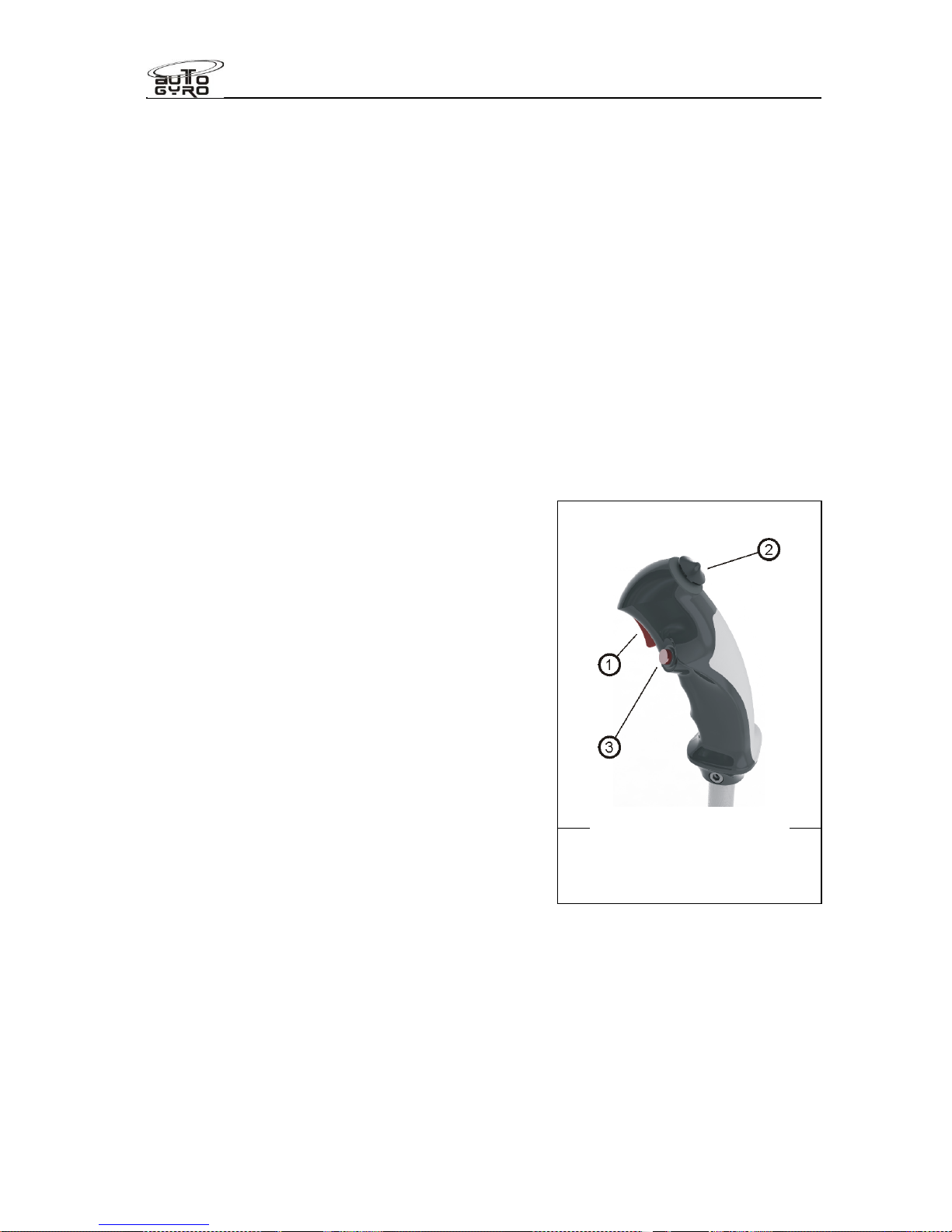
Flight Manual
Cavalon
SECTION 7
SYSTEM DESCRIPTION
RSUK0287_POH_Cavalon Revision 3., Issue Date 06.04.16 7-5
to compensate for asymmetric air flow in forward flight the blades are free to teeter. The
hinge assembly consists of teeter tower, teeter bolt and teeter block.
The rotor system fitted to Cavalon differs from the standard RotorSystem II in that the blade
AOI is 0,4deg less. This is identified by the rotor blade assembly part no and black spacers
fitted between the hub bar and rotor blade. RotorSystem II TOPP is also permitted for use
on Cavalon. TOPP rotors carry blue end caps as opposed to red end caps, and clear
anodised spacers instead of black.
The teeter bolt runs in a long Teflon coated bushing in the teeter block (main bearing
action), as well as two shorter bushings in the teeter tower (emergency bearing action). The
main bearing action is supported by special grease which is applied through a grease nipple
on top of the teeter block. Servicing is described in SECTION 8 of this manual.
7.9 Vibration Damping
A certain level of vibration is inherent to any 2-bladed rotor system. In order to reduce
vibration levels to a minimum, a vibration decoupling element in the rotor mast isolates rotor
vibration from the fuselage.
7.10 Flight Controls
Rotor head and trim control
Pitch and roll of the gyroplane are controlled by
tilting the complete rotor head by means of the
control stick. Control input is transferred via torsion
tube and linkage running below the seats to the
base link and from there to the rotor head via pushpull control cables.
The control stick head is ergonomically shaped to
fit the pilot’s right hand and features control buttons
for radio transmission (1), a four-way trim function
(2), and activation of the pre-rotator (3).
The trim control works as a classical 4-way beep
switch. Pulling the beep switch back increases aft
trim or nose-up tendency, while pushing the switch
forward reduces back trim pressure, leading to a
nose-down tendency. Roll trim is effected by
pushing the trim switch to the respective side.
Because of a safety circuit, activation of the pre-rotator is only possible with the pneumatic
mode selector in FLIGHT position and the control stick fully forward. This prevents
inadvertent activation of the pre-rotator during flight or in BRAKE mode.
The LH flight controls must never be restricted by passenger or objects. Passengers must
be briefed.
Rudder and front wheel control
The rudder is connected to adjustable foot pedals with steel cables which are routed
through the lower fuselage and inside the keel tube. Both pairs of pedals are
Control stick head
1 – Radio transmission
2 – Trim switch
3 – Pre-rotator
Page 94
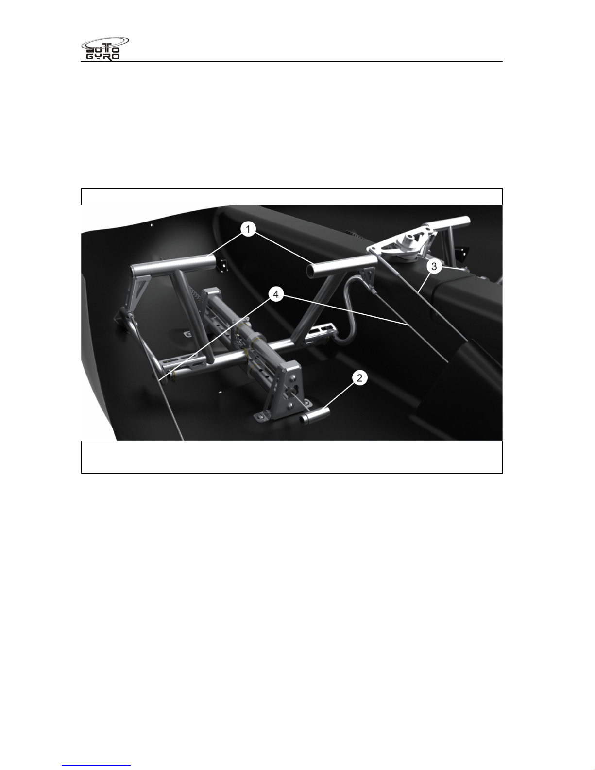
Flight Manual
Cavalon
SECTION 7
SYSTEM DESCRIPTION
RSUK0287_POH_Cavalon Revision 3., Issue Date 06.04.16 7-6
interconnected. The nose wheel steering is directly linked to pedal/rudder control input by
redirected cables.
Both pairs of pedals can be adjusted to suit different leg lengths. A shorter adjustment is
achieved by pulling the handle which moves the pedals closer. Pulling the handle while
pushing with both feet gently against the pedals allows longer adjustment.
After adjustment make sure the pedal assembly is properly locked, as indicated by a definite
and positive click.
Pedals (left hand side
shown
) with adjustment possibility
1 – Pedals 3 – Nose wheel steering cables
2 – Adjustment handle 4 – Pedal control cable
The rudder is fitted with a trim tab. This is normally biased to the left, and may be adjusted
by the operator to trim the aircraft for straight flight at a desired speed, feet off the pedals.
Adjusting it to the left will biase the rudder to the right and vice versa.
Page 95
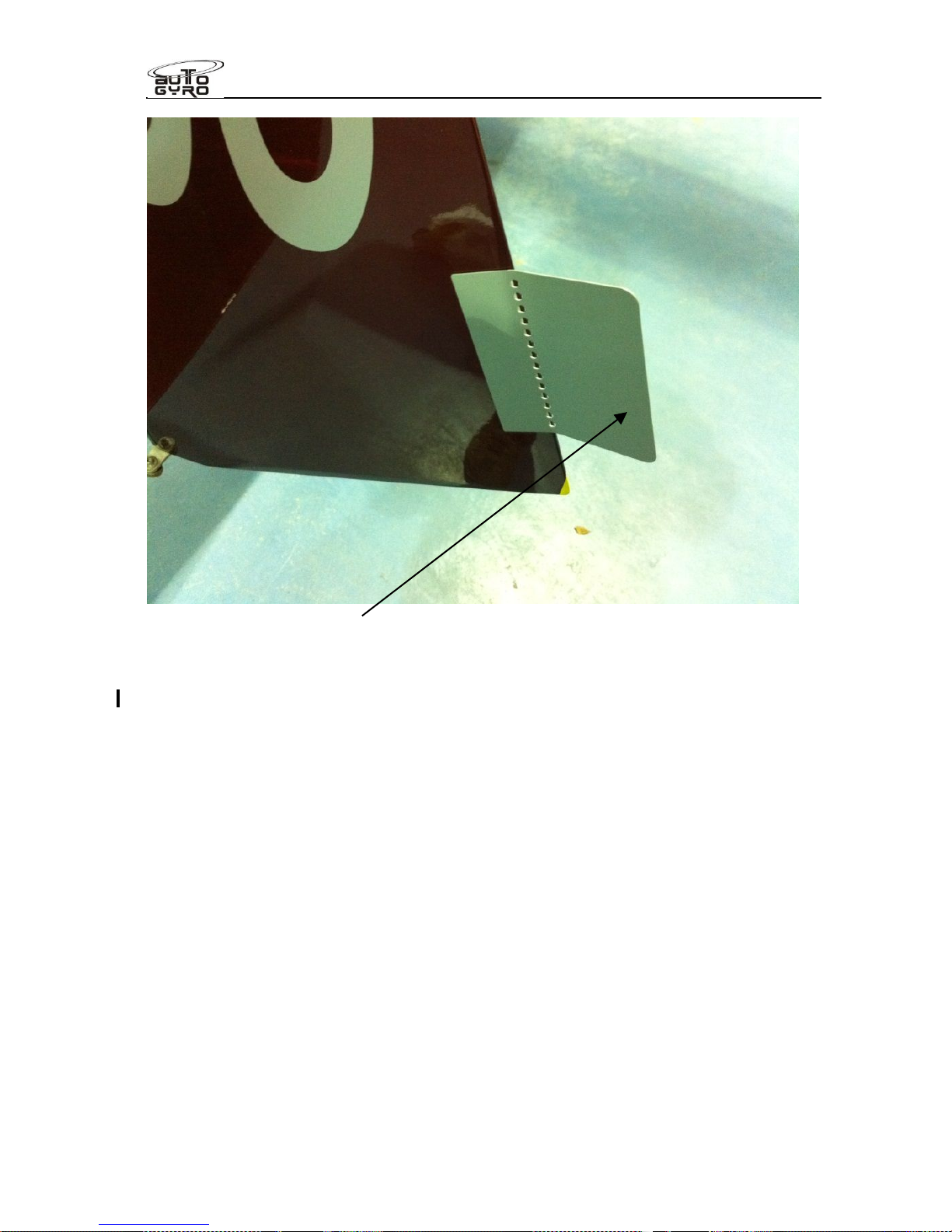
Flight Manual
Cavalon
SECTION 7
SYSTEM DESCRIPTION
RSUK0287_POH_Cavalon Revision 3., Issue Date 06.04.16 7-7
Trim tab fitted to the rudder
Throttle and brake panel
The throttle and brake panel with choke and cabin heat / cabin temp control is located on
the left side of the pilot station in the centre panel. Throttle control (1) is conventional with
IDLE in aft (or pulled) and full throttle in most forward position. With the ROTAX 914 UL
engine the boost range is entered by overcoming a small resistance to the front. The throttle
lever is linked with cable controls to the carburettors. A mechanical spring applies tension to
the control cables and brings the carburettors to full throttle in case of a cable break. The
throttle lever has a pre-set friction brake which holds the throttle in the selected position.
Choke (3) is used start a cold engine. In order to do so, pull the choke lever fully to the rear
or ON position and be sure to have the throttle in idle position. After starting the engine and
a short warm-up, the choke can be slowly disengaged by moving the lever into its forward or
OFF position.
The hydraulic wheel brake is actuated by pulling the brake lever (2). A locking pawl
mechanism allows setting for use as parking brake. In order to release the parking brake
pull the brake lever a little further to let the spring-loaded locking pawl disengage, and then
release wheel brake.
Do not try to disengage the locking pawl by pressing the small release lever without pulling
the brake lever at the same time. Releasing the pawl using the small release lever only will
lead to premature deterioration of the teeth. If the teeth are worn the function of the parking
brake will be compromised!
Page 96
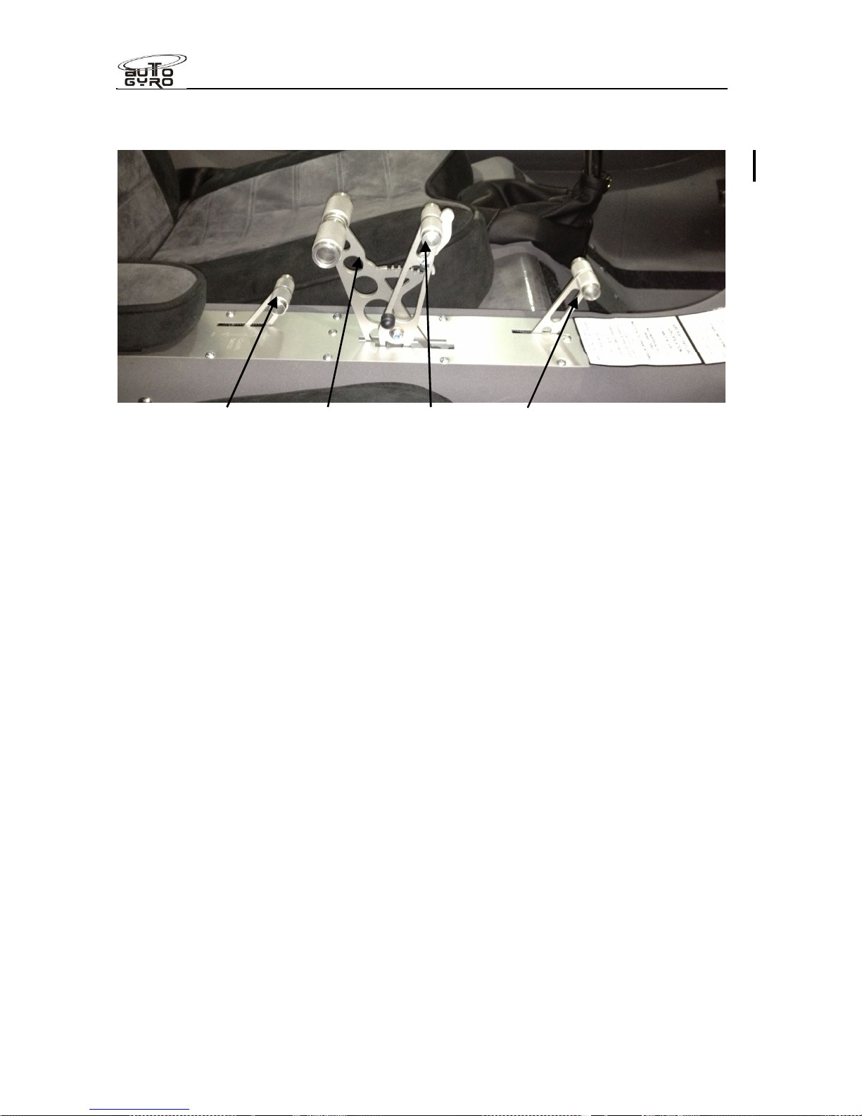
Flight Manual
Cavalon
SECTION 7
SYSTEM DESCRIPTION
RSUK0287_POH_Cavalon Revision 3., Issue Date 06.04.16 7-8
The quadrant also features the control for cabin heating / air conditioning system (4). All
controls are labelled correspondingly by engraved text and symbols on the cover plate.
Heater control (4) Throttle (1) Brake lever (2) Choke (3)
7.11 Electrical System
The 12V DC electrical system consists of an engine driven electrical generator, a battery,
master switch, indicators, switches, electrical consumers, and cabling. With the ROTAX 914
UL engine an electrical power supply is vital for continued engine operation as this engine
variant solely relies on electrically driven fuel pumps.
Turning the master switch to the ON position closes the battery contact and energizes the
gyroplane’s electrical system. The red LOW VOLT warning light will illuminate briefly as a
functional check. A steady indication, however, warns the pilot that the voltage of the
system has dropped below a safe value. In this case a safety circuit (load shedding relay)
will automatically disable the aircraft lights and the 12V power receptacle. This is often the
case when turning the keyswitch on, and the lamp should extinguish once the engine is
running and the regulator supplying sufficient electrical energy to meet demand.
A red GEN warning light is installed to indicate that the battery is not being charged.
Turning the keyswitch on (if fitted with a 914UL engine) will also energise the regulator
relay, and provide electrical energy from the battery to the primary electrical fuel pump. This
relay is to protect the engine fuel supply in the event of a cabin primary fuse failure, or a
battery short circuit, enabling engine fuel supply to continue in those circumstances.
Seat heating note. The optional seat heat is actuated by depressing the rocker switch
between the seats to either (I) or (II) heat setting (with the switch centred for OFF). The
heater element is self regulating to that setting. The seat heating requires considerable
energy, and is recommended to be left OFF (or at least reduced to heat setting (I)), once the
cabin heater and cabin is up to temperature (around 5 minutes).
Note that the seat heating elements will only work when the LOW VOLT warning LED is
OFF, being automatically disconnected when the voltage falls below the LOW VOLT relay
threshold.
Warning! High electrical load in flight with low engine rpm may reduce the ability of the
charging circuit to replenish the battery, thereby reducing the battery reserve in the event of
a charging circuit failure. Illumination of the LOW VOLT warning lamp lights demonstrates
Page 97
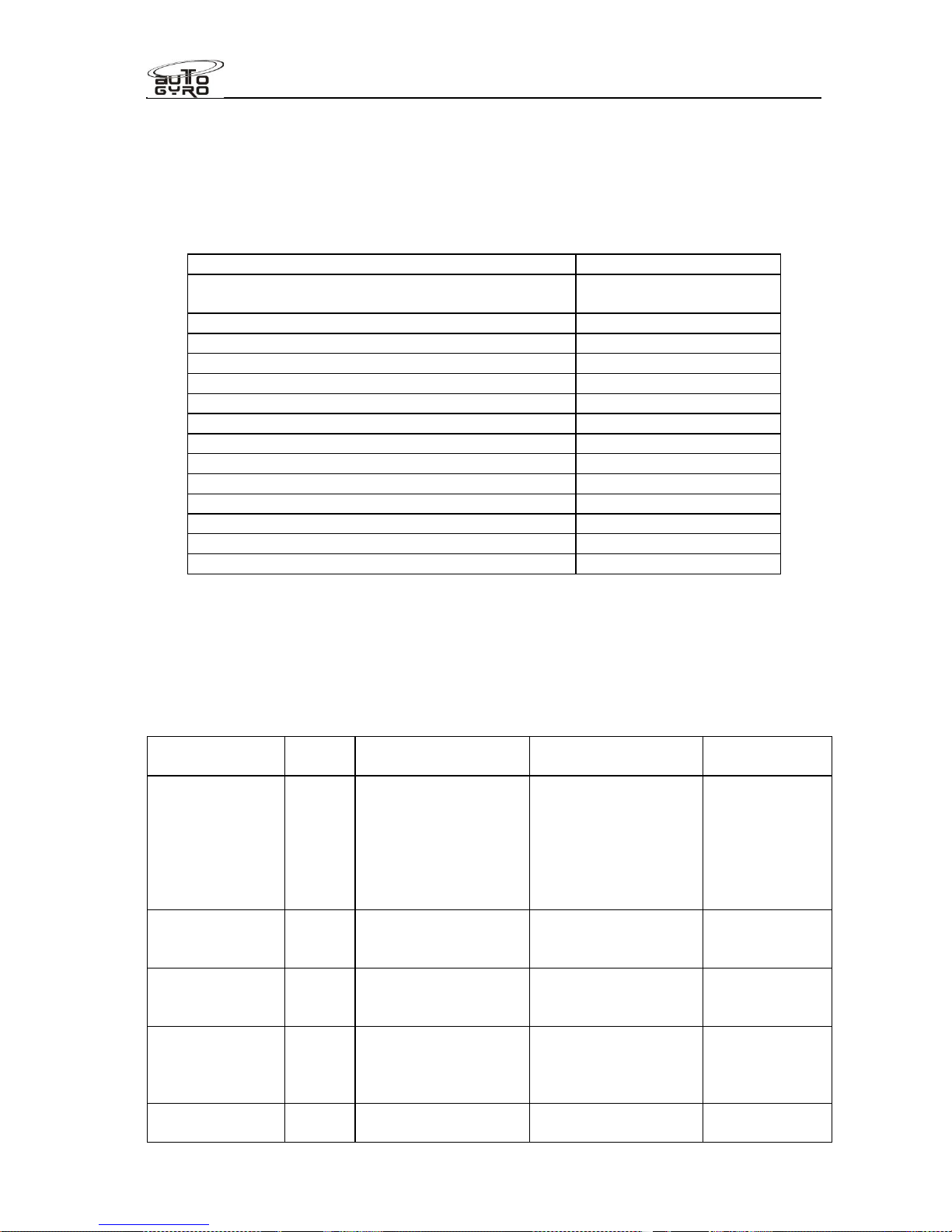
Flight Manual
Cavalon
SECTION 7
SYSTEM DESCRIPTION
RSUK0287_POH_Cavalon Revision 3., Issue Date 06.04.16 7-9
that the electrical system voltage has dropped below 12v, and, provided the charging circuit
is working, that the electrical demand has exceeded supply. If lit, or intermittently lit, either
reduce the electrical load or increase generator circuit output by increasing the engine rpm,
as safe or appropriate to do, such that the lamp remains off.’
The power consumption of individual equipment is listed in the following table:
Equipment / System
Power load
Generator maximum (see Rotax handbook for
output curve v engine RPM)
(-) 240 W
Electrical fuel pump 21 W
Pneumatic compressor 124 W (peak) / 103 W
Engine cooling fan 194 W (peak) / 97 W
Seat heating 86W/seat peak
Cabin heat blower fan 32 W
Equipment / System
Power load
Strobe lights 28 W
NAV lights (LED) 9 W
Landing light (LED) 10 W
Radio ATR500 2 W (rcv) / 35 W (xmt)
Radio ATR833 7 W (rcv ) / 35 W (xmt)
ATC Transponder TRT800H max. 10 W
Ipad 12 W
7.12 Lighting System
The aircraft is approved for day VFR operation only. Position lights, landing light and
strobes are available as optional equipment. If installed, refer to SECTION 9 of this manual.
7.13 Electrical circuit protection
Fuse
description
Rating Protects Fuse type
Location
Main incoming
supply to
cockpit
40A Main positive supply
is fed to the starter
solenoid from the
battery. The supply
continues then
through the 30amp
fuse to the cabin.
Bolt in strip type,
MTA S.p.A.
“Midival” range
30A rating
Engine bay
fuse box, left
side within
inner firewall
Compressor 10A Only supplies the
pneumatic
compressor
CB Inst. Panel
Regulator relay
(914UL engine
variant only)
1A Regulator Relay
circuit
CB Inst. Panel
Primary fuel
pump (914UL
engine variant
only)
5A Fuel pump P1 Blade fuse Near fuel
pump in pump
harness
Secondary fuel
pump
5A Fuel pump P2 CB Inst. Panel
Page 98

Flight Manual
Cavalon
SECTION 7
SYSTEM DESCRIPTION
RSUK0287_POH_Cavalon Revision 3., Issue Date 06.04.16 7-10
914UL TCU 2A Engine control unit CB Inst. Panel
Cockpit 5A All electrical gauges
(rotor and engine
rpm, oil pressure,
water and oil temps,
fuel gauge) and
warning lamps
CB Inst. panel
Radio 5A Radio (transceiver) CB Inst. panel
Transponder 5A Transponder CB Inst. panel
Alt 5A Accessory
instruments (e.g.
Attitude Indicator)
CB Inst. panel
GPS 5A GPS or iPad with
navigation software
CB Inst. panel
Flarm (where
fitted – not
applicable to
UK aircraft)
1A Flarm anti-collision
system
CB Inst. panel
Lights 5A Landing lights CB Inst. panel
ACL 5A Nav and Strobe
lights
CB Inst. panel
Start 5A Starter relay and
SMD module
CB Inst. panel
Variable pitch
propeller
(where fitted)
16A Pop out circuit
breaker for propeller
and propeller
controller.
CB Inst. panel
Fan 10A Power supply to
engine cooling fan
CB Inst. panel
Trim 2A Supplies power to
the stick controls for
operating the
pneumatic solenoid
valves and the
compressor relay
CB Inst. panel
12v plug 5A Accessory socket CB Inst.panel
Heat 16A Electric seat heating CB Inst panel
Rotax regulator 25A Charging circuit
from regulator to
battery/aircraft
supply
MTA S.p.A.
“Midival” range
25A rating
Engine bay
fuse box, left
side within
inner firewall
Starter 100A Primary supply from
battery to startersolenoid /starter and
from starter solenoid
to main fuse
MTA S.p.A.
“Midival” range
100A rating
Engine bay
fuse box, left
side within
inner firewall
External
battery charge
point (where
fitted)
15A Protects cable from
short circuit when
fitting or removing
the cowls
Cartridge fuse Line-fuse near
battery
Heater 5A Cabin heating fan
located in nose of
Cartridge fuse Line-fuse in
centre-
Page 99
Flight Manual
Cavalon
SECTION 7
SYSTEM DESCRIPTION
RSUK0287_POH_Cavalon Revision 3., Issue Date 06.04.16 7-11
aircraft console
powered from
“Heat” CB
Note that the external charging point permits charging via a Ctek charger
CAUTION
Do not reset CB’s in flight unless essential for continued safe flight
7.14 Avionics
Radio.
Option fit is the Funkwerk ATR500 radio for both external and internal communications. The
wiring harness terminates in a standard jack plug type connection at each seat, and the
antenna may be mounted inside the nose, or underneath the enclosure. Ensure the
headsets chosen function correctly before flight, and refer to the radio’s User Manual.
The radio EASA approval number is LBA.0.10.911/113JTSO
Optionally a Funkwerk ATR833 may be fitted, approval no EASA.21O.0193
Transponder.
Option fit is a Funkwerk TRT800H Mode S transponder. The antenna protrudes under the
body. Read the User Manual for operational instructions, and take care that the Mode S
hexadecimal code and aircraft recognition data is correct!
The Funkwerk TRT 800H carries an EASA approval, approval no. EASA.210.269
Remark; A Radio Operators licence is required to allow use of the radio, and a Radio
Installation licence is required for the radio and transponder (one combined licence,
renewed annually).
Page 100

Flight Manual
Cavalon
SECTION 7
SYSTEM DESCRIPTION
RSUK0287_POH_Cavalon Revision 3., Issue Date 06.04.16 7-12
7.15 Instrument Panel
Different instrument panel layouts are available. The basic instrumentation arrangements
include:
Standard Layout Standard layout with Ipad mounting
The standard layout includes all instruments necessary for flight but also installation
provisions for additional conventional instrumentation.
The panel layout include all relevant instruments arranged in a way to accept most off-theshelf moving map navigation devices on the left of the panel. At the point of manual release,
the only device accepted for fitment is the Ipad. For detailed user information and
instructions concerning the different moving map systems available for use on the Ipad,
please refer to the manufacturer’s documentation.
The Ipad is only permitted as an unapproved GPS or as an Electronic Flight Bag (EFB). An
EFB means that the Ipad may be loaded with the aircraft manuals and associated
documentation. Use of information displayed as an alternative to VFR flight is NOT
approved. The pilot is recommended to review the CAA’s GA SafetySense leaflet 25 ¨Use of
GPS¨ (downloadable from www.caa.co.uk/safetysense).
It is the operators responsibility to ensure any information and software stored in the Ipad is
up to date. The Ipad itself is not supplied by RotorSport, and has not been approved to any
airworthiness standard.
NOTE
Any moving map system shall be used for reference only and does not replace
proper flight planning and constant oversight and awareness.
WARNING
All GPS display units requires regular updating of the map displays and
potentially, the basic software itself It is the operators responsibility to ensure
the equipment is correctly updated prior to flight, and to understand that the
GPS system is NOT a primary navigational aid. The GPS system (or any other
information displayed on the Ipad) has not been approved to any airworthiness
standard.
Depending on the chosen instrumentation and optional equipment, the depicted panels on
the following pages may vary. Note that the standard or back-up compass is mounted to the
glare shield.
Some hand held GPS units and antennas emit magnetic fields that vary with respect to time
and/or levels of battery charge. These may change your compass deviations, so always
cross check between the compass headings with your GPS installed and placard
accordingly if required.
 Loading...