

Page 1
©2018 Autogrow Systems Ltd V4.5
IntelliClimate
Installation and User Guide
• USB connection to PC or Mac
• Advanced cloud connectivity enabled as standard (using gateway software)
• Integrated control of all grow room parameters
- 2 banks of lights
- cooling fan
- second cooling fan or AC
- heater
- dehumidifier
- humidifier (or fogger)
- CO2 injection
• Measurement of all relevant grow room parameters
- Air temperature
- Relative Humidity
- Light level
- Second sensor set optional
- CO2 level (0.5000ppm) optional
- Outside temperature (optional)
- Intruder detect
- Lamp over-temperature detect (optional)
• Extensive fail-safe features
• Settings can be scheduled to automatically change to match plant growth
stage
• Autolearn – self learning automatically adjust CO2 cycle times to minimise
wastage
Page 2
IntelliClimate Manual
©2018 Autogrow Systems Ltd V4.5 2
Compliance Declaration - International regulations and codes
This equipment is designed for commercial use and complies
with the following regulatory codes:-
USA
Compliance with FCC Part 15 Class A
This equipment has been tested and found to comply with the limits for a Class A
digital device, pursuant to Part 15 of the FCC Rules. These limits are designed to
provide reasonable protection against harmful interference when the equipment is
operated in a commercial environment. This equipment generates, uses, and can
radiate radio frequency energy and, if not installed and used in accordance with the
instruction manual, may cause harmful interference to radio communications.
Operation of this equipment in a residential area is likely to cause harmful
interference in which case the user will be required to correct the interference at his
own expense. The end user of this product should be aware that any changes or
modifications made to this equipment without the approval of Autogrow Systems Ltd
could result in the product not meeting the Class A limits, in which case the FCC
could void the user's authority to operate the equipment.
Europe
This product has been tested and found to comply with EC requirements for
commercial equipment and carries the CE mark
Radiated Emissions
EN55022 Class A
Conducted Emissions
EN55022 Class A
ESD
EN61000-4-2
(IEC 801-2)
Radiated Immunity
EN61000-4-3
ENV50204
(IEC 801-3)
EN55024
Australasia
This product has been tested and found to comply with C-tick requirements
for commercial equipment EN55022 (CISPR 22) Class A
RoHS
This product is free from lead and other heavy metals
Although this product is exempt from the RoHS regulations as it is classified as
Category 9 Monitoring and control Instrument it is nevertheless made with RoHS
compliant components and assembled using lead free solder.
Even so, it should be recycled at the end of its life and it may be returned to the
distributors in your region for recycling or safe disposal.
Page 3

IntelliClimate Manual
©2018 Autogrow Systems Ltd V4.5 3
Contents
Quick-start page with helpful hints
Section A Introduction (all users should read this first)
Section B Software overview
Section C Installation
Section D Software installation
Section E Maintenance
Section F Fault finding
Section G Warranty
Disclaimer:
Suggested settings are made in good faith and with care and consideration. However,
Autogrow can accept no responsibility for the accuracy or appropriateness of
suggestions or the outcome resulting from their use.
Page 4

IntelliClimate Manual
©2018 Autogrow Systems Ltd V4.5 4
Quick-start
This is not a substitute for reading the relevant sections of the manual but is
included to emphasise some important and useful points.
If the grow room is to be operated at high humidity for long periods (e.g. during
cutting/rooting stage) it is preferable to mount the controller outside the grow room.
This is easily done as the grow room sensors are supplied with a long 5m (15ft) cable
and if necessary this can be replaced with a longer cable. If this is done then data
cable such as CAT5 computer network cable should be used. This should be
stranded cable (rather than solid core) to avoid breakages.
Note that one sensor unit (to measure temperature, RH and light) is supplied as
standard and a second optional sensor unit may be attached. This is useful in larger
grow rooms or where increased security is required. Control will normally be based
on the average readings from the two sensors but should one sensor fail, control will
automatically revert to the working sensor. The optional outside temperature sensor
is useful in very cold and very warm climates.
If you intend injecting CO2 then air-cooled lights are strongly
recommended and if you are in a warm climate then an air conditioner
and humidifier should also be considered. Together, these will allow longer
periods of CO2 injection to occur without the need to vent the room and this will lead
to significant improvement in growth rates with lower use of expensive CO2.
SAFETY NOTE: If you do inject CO2 into the grow room always do the following
before entering.
1) Disable CO2
IntelliClimate
1 or 2 environment sensors
connecting to IntelliClimate.
Each measures temperature, RH
and light level
Outside
temp sensor
Air inlet
CO
2
Intruder
sensor
USB cable
Typical grow room layout
CO
2
Ballas
Relay box
Dehumidifi
Heater
Fan2 or aircon
Fan1
Page 5

IntelliClimate Manual
©2018 Autogrow Systems Ltd V4.5 5
2) Force on fans
3) Leave door open whilst inside
Section A - Introduction to the IntelliClimateTM grow room
controller
The IntelliClimate is, without doubt, the most advanced and user-friendly grow room
environment controller on the market. It has a wide range of possible applications
which we will discuss briefly in this section. To keep the user interface as simple as
possible, only the readings and settings relevant to the selected features are
displayed on the controller’s LCD and on the computer. To add extra features, you
have to select them by going into the configure menus on either the controller or the
computer.
Features
A full specification is attached as appendix 1. Here we will review the main features
available to you. Remember, to enable any feature mentioned you will need to go
into the configuration menus on either the controller or computer to select them.
When the controller is supplied it is normally pre-set as a simple fan cooled
environment controller with CO2 injection disabled.
The controller can operate in a number of modes ranging from a simple cycle timed
mode to a sophisticated system that makes optimal use of a range of attached
equipment. After installing the unit, you need to enter the configuration section and
select (check) all the equipment that you have connected. Once the controller knows
what you have attached to it, it will automatically select the most appropriate mode of
operation.
Lighting
The controller can switch two light banks. It is always a good idea to split your lights
into two groups. Firstly, when using both banks together, it allows the controller to
stagger the switch on times so that the power surge from the first bank has subsided
by the time the second bank comes on. Secondly, during the vegetative phase of
growth, the lights are on for longer periods (18hours) but a lower intensity may be
used. The controller has the ability to switch on one bank and alternate the banks
each day. This ensures that the plants receive light from both sides. If, when one
bank is turned on, the light sensor detects a low light level the controller assumes that
that bank is out of action (bulb blown) and automatically switches on the other bank.
If alarms are enabled, then it will alert you to the fact that a light has failed. Similarly,
if a power failure occurs, the controller has a settable detent before bringing the lights
back on in stages. This is extremely useful when you have more than one grow room
as all the lights can be sequenced to come on one by one to avoid a huge power
surge. In addition, the controller automatically checks the duration of the power
outage and ensures that minimum cool down periods are complied with. This has a
significant impact on lamp life.
Page 6

IntelliClimate Manual
©2018 Autogrow Systems Ltd V4.5 6
For those using air cooled lights, it is possible to fit small over-temperature cut-offs to
avoid them overheating if the cooling fans should ever fail.
Hint: fit the cooling fan to blow air through the light fittings rather than suck out the hot
air. This way the fans run cooler and last a lot longer.
Fans
The fans may be used for cooling, humidity reduction, air changes and to bring in
ambient CO2 (if CO2 injection is not used at that time). During the day when CO2 is
being injected, other means to control temperature or humidity will be used in
preference to the fans which will only be used to force an occasional air change and
provide a fail-safe if the aircon or dehumidifier fails.
For simple systems that have CO2 injection but do not have aircon or
dehumidification, the controller will operate as a cycle timer system with three timed
phases 1) fans on, 2) fans off, inject CO2 and 3) stop injecting CO2 and wait while
plants absorb CO2 then repeat cycle. In this mode, the controller will self-adjust the
timings if it finds that CO2 is being wasted due to the fans being forced on by heat or
humidity build up before the plants have time to use the CO2. If this situation is too
bad it will stop injecting CO2 and will revert to maximum venting (within temperature
limits) to bring in as much ambient CO2 as possible.
Humidifier or fogger
This output can drive either a standard fan based fogger or ultrasonic humidifier or
alternatively, a nozzle type fogger. When humidifier is selected the function is very
simple with the humidifier coming on when the humidity is too low and going off when
it is satisfactory. In the case of the fogger selection, the operation is similar except
when it is calling for humidification the output is pulsed on and off producing small
puffs of fog and allowing time for each puff to dissipate before the next.
Heater, Dehumidifier, and CO2
The purpose and function of these devices is self-explanatory and they will all work
to keep the temperature, humidity and CO2 close to the settings. In the advanced
settings, you will also find switching offsets settings for each device that allow you to
set the offset from the main setting at which it will turn on and another offset at which
it will turn off. Although these come preset to typical values that will avoid excessive
overshoot or rapid cycling in most grow rooms it is possible for the user to customise
then to achieve optimal performance.
Software
Please head to our online Help, found here: help.autogrow.com/intelligrow.
Selection of units
You may select either degrees C or degrees F for temperature. CO2 concentration
is measured in ppm and for the more advanced user VPD is measured in kPa/m2.
The date format is selectable between mm/dd/yy and dd/mm/yy formats
Page 7

IntelliClimate Manual
©2018 Autogrow Systems Ltd V4.5 7
Fail safe operation
This controller has many fail safe functions built in and we have already mentioned
some above. There are fail safes that will force on the fans if the air con or
dehumidifier fail, others that will stop the CO2 if the door is opened (if intruder alarm
fitted) and others that will switch over lights if a bulb fails or switch off lighting if the
air-cooled shades overheat. If CO2 should run out or stop working, the controller will
detect this and revert to maximising the intake of ambient CO2. These are in addition
to the power-fail light-on sequencing
Advanced settings and rules
These settings and rules are pre-set to typical values that will suit the majority of grow
rooms, however, expert users may wish to alter them to achieve optimal performance.
Note that the advanced settings are only accessible via IntelliGrow and are not
available from the controller LCD menu system. If these are ever changed and the
operation of the controller becomes incorrect, there is a button at the bottom of the
screen which can be used to return the advanced settings to the factory default state.
Please head to our online Help, found here: help.autogrow.com/intelligrow.
Alarms
The alarms can be enabled to operate on the controller buzzer, the computer via it's
sound card or to text you when using IntelliGrow. Each of these can be silenced or
enabled. Any enabled alarm will sound when a relevant reading deviates outside
user set limits. For humour, we have a selection of alarm sounds including regular,
fun and adult. These can be selected on IntelliGrow under setup.
Please head to our online Help, found here: help.autogrow.com/intelligrow.
Outputs
The outputs voltages are all dependent on the power supply adapter used. A 24V DC
power is normally provided with the unit in which case all outputs will be 24V DC.
Power supply
The controller requires a power supply between 12V and 24V either AC or DC.
Whatever power is applied will appear at the outputs (when they are ON). The default
power adapter included with this controller is 24V DC which is compatible with the
relay boxes and power relays that we have available. This power supply has a
universal input voltage from 100V to 240V 50/60Hz. Note that the controller outputs
of are limited to a current of 1.2A (inductive) and 3A (resistive) load. The power supply
should be sized according to the maximum load that can be applied at any one time.
The maximum total draw at any one time should not exceed 4A.
Normally we supply a universal input (any voltage and frequency within wide limits),
24V DC output power supply but this could be changed in the future or by request.
Page 8

IntelliClimate Manual
©2018 Autogrow Systems Ltd V4.5 8
How to use this manual
The IntelliClimate has a number of advanced modes of operation and so we have
divided this manual into sections, each of which represents a particular feature.
For installation advice, go to the installation section at the back of this manual and
then start by reading sections B and C.
Getting Started
Follow the installation instructions in the installation section and when everything is
installed and connected do the following.
Switch on the power. Check that the power light on the front panel is on and that the
LCD display has some information on it.
From here, you need to create your IntelliGrow account. Please head to our online
Help, found here: help.autogrow.com/intelligrow
Once you have your Intelligrow account setup, you can install the IntelliGrow
Installer. You’ll need to select either Windows or Mac setup, depending on what
computer/operating system you are using.
Please head to our online Help, found here: help.autogrow.com/intelligrow.
If you have more than one new controller, connect their USB cables one-at-a-time
and when the software asks, provide the requested information. For new or
replacement controllers, you'll be asked which grow room it's located in and then to
give the controller a name.
Use a short meaningful name like Doser1, Climate2 etc so that understanding which
device is located in which area is simple to understand as you add more devices.
IntelliGrow will automatically detect any connected controllers and will communicate
immediately. You will also see information from the controller(s) on your computer
screen.
Page 9
IntelliClimate Manual
©2018 Autogrow Systems Ltd V4.5 9
Section B – Software overview
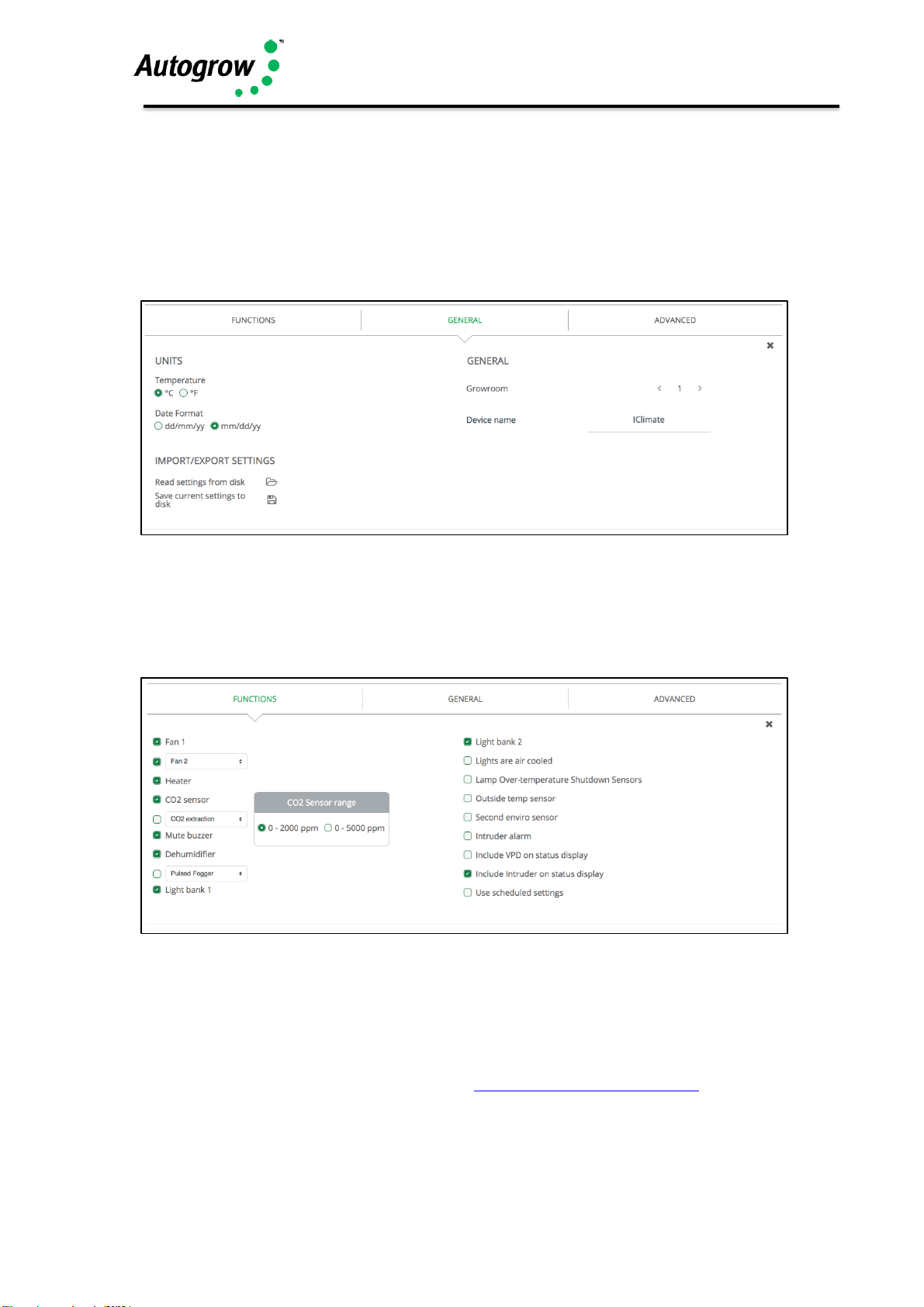
Configuration
Under 'General' you can change the units to measure temperature, your date
format, set the number of Grow Room's you have and name your devices. You can
also import/export settings and save your current settings locally.
Under 'Functions', you need to check each devices' checkbox that you've installed.
Some devices share one output so you can only select one device or the other. The
software enforces this and when one is selected the other is automatically “greyed
out”. If you want to select the greyed device, you must de-select the other one first.
After changing any settings, click the 'Save' button at the bottom-right of IntelliGrow.
Once you've selected all the installed and working devices, you can select whether
you want to use Autoset (scheduling), Autoset (growth stage) or manual settings.
Please head to our online Help, found here: help.autogrow.com/intelligrow
Page 10

IntelliClimate Manual
©2018 Autogrow Systems Ltd V4.5 10
Autoset (Scheduling)
If this is selected, a table will appear on the settings tab. Here you can choose to
read in a schedule from disk. This could be a ready-made schedule or one that you
or a friend have previously created and saved to disk. Alternatively, you can create
a schedule from scratch and then save this for future use.
The idea of a schedule is that you can preload a typical growing sequence so that the
environment automatically changes to match the requirements of the crop. Each line
in the table is specified by a day number (and date) and specifies the settings
required. These settings stay in effect until the date of the next line has been reached.
For instance, you will probably start your new plantlets with a high humidity, a single
(alternating) light for 18 hours per day and with a relatively low CO2 level of say
500ppm. Then every two days you will set the schedule to automatically lower the
RH a little and raise the CO2. During the first week or so you may also have a
day/night temperature drop of 5 or 6 degrees. Then after that you may want to reduce
the night drop for a week or two to help prevent too much stretch and produce shrubby
plants.
All this and more can be entered into the schedule so that the environment exactly
matches the growth stage of the crop. If plant growth is slower or faster than expected
it only takes a few minutes to modify the schedule.
Lines can be added or deleted from anywhere in a schedule by clicking on the + or X
symbols at the top which makes for very simple editing whenever changes are
needed.
Note that the schedule is stored on IntelliGrow and so changes will only come into
effect if IntelliGrow is connected to the controller. If not connected, the settings will
be updated as soon as IntelliGrow is reconnected to the controller on, or after, the
date of the change specified.
Please head to our online Help, found here: help.autogrow.com/intelligrow
Autoset (growth stage)
This function can be used to set the controller approximately to the correct fixed
settings for any particular stage of growth. Once set the settings will stay at those
values until they are changed. If Autoset is selected a “growth stage” selector box
appears on the status tab. In this you select from a list of growth stages and the
setting will automatically adjust. The selector box will continue to show the growth
stage selected but if you edit any setting then the selector box label will change to
“user defined”
Manual settings
This allows you to enter fixed settings just like in “the good ole days”.
Advanced settings and rules
These settings and rules are preset to typical values that will suit the majority of
grow rooms, however, expert users may wish to alter them to achieve optimal
performance.
Page 11

IntelliClimate Manual
©2018 Autogrow Systems Ltd V4.5 11
Switching offsets
This group of advanced settings refers to the exact point at which a device is switched
on or off. The idea is to always have a small differential between the switch ON point
and OFF point to avoid device switching on/off too rapidly as this would cause
unnecessary wear on the relays and output devices. The switching offsets are also
useful to avoid overshoots that invariably occurs when a heater or CO2 is switched
off.
We will look at each setting in turn and make suggestions for initial settings which will
normally be pre-programmed in when the unit is manufactured. After observing your
grow room operating you may decide to change some settings slightly.
Fans ON (+0.2C) OFF(-0.8C)
This setting applies to both fans (if two installed), the second fan coming on after the
first has been on for two minutes and temperature is still above the ON point. Note
that reducing the difference between ON and OFF will result in the fans switching
ON/OFF more often with increased wear to both the fans and the relays.
AirCon ON (+0.2C) OFF(-0.8C)
This is the same as for the fans. Note that auto switching from Fans to aircon has a
separate rule. Normally, this rule will be to switch over to aircon at say +2C. Once in
aircon mode it will stay there until the next time zone or if the temperature falls below
the heater ON temp.
Heater ON(-1.5C) OFF(-0.5C)
This gives a buffer of 0.7C between the heater going OFF and the Fan coming on.
This may need to be increased a little if it is ever observed that the fan comes on soon
after the heater going off.
Humidifier ON(-10%) OFF(-2%)
Dehumidifier ON(+10%) OFF(+2%)
These settings give a difference of 12% RH between one device switching off and the
other switching ON. This may need to be increased if you find one switching on soon
after the other has switched off
CO2 ON( -200ppm) OFF(-100ppm)
This means that the CO2 will switch on when it falls below 200ppm under the setpoint
and will switch off as soon as it exceeds 100ppm below the setpoint. The reason for
switching off before the setpoint is reached is that there is always some overshoot
with CO2. Depending on your exact setup you may need to alter this to achieve what
you desire.
Advanced Rules
Each rule is listed below with a brief description and a suggested initial value
Page 12

IntelliClimate Manual
©2018 Autogrow Systems Ltd V4.5 12
Heater inhibit
When changing from night to day prevent heater for switching on for 15 minutes. We
know that when the lights come on the grow room will warm up quickly so we prevent
the heater from coming on just before the lights will come on.
Minimum air change rules
Force fan ON for Day: 2 mins 0 secs every 1 hrs 30mins
Night: 0 mins 30 secs every 4 hrs 0 mins
This will force an air change if the fans have not been operating for other reasons.
This will expel humid stale smelly air and bring in ambient CO2. You may want to
change these settings between winter and summer.
Allow minimum air change while aircon is operating (Tick)
It is good practice to allow minimum air change even when air conditioning is active
to expel methane and other stale smelly air
CO2 rules
Inject CO2 (only when not venting or) (when only F1 is running)
Inject only if measured light greater than (100 J/m2/sec)
If hot, and frequent venting is required, then reduce CO2 to avoid wastage (tick)
Most people will want to avoid wastage and will set the system to only inject CO2
when NOT venting. In fact, the controller will anticipate when venting is required and
will minimise wastage by stopping CO2 injection well before venting starts
The second rule ensures that there is adequate light before injecting CO2. This is
useful in a glasshouse using natural sunlight in which case it might be set at 400J but
in a grow room it is just useful to check that the light has indeed come on in which
case a setting of say 50J is more suitable.
The last rule is for a system that is injecting CO2 on a cycle timed basis. If checked,
this rule will modify timings to try to avoid CO2 wastage and will completely abort CO2
injection if it is uneconomic. This uses the Autolearn feature of the IntelliClimate
Lighting rule
This rule specifies the minimum gap between light bank1 switching on and light bank
2. Normally, 6 minutes is sufficient to allow the power surge from the first bank to
subside before the second bank switches on. If electronic ballasts are used it may
be possible to reduce this time.
Setpoint ramping
When changing between day and night settings this rule allows a period of time for
the settings to change gradually, or ramp, from one value to the other. If this is made
too abrupt you can shock the plants and also cause fail safes and alarms to operate
as the system fails to respond quickly enough to the new settings. 15 or 20 minutes
is usually sufficient.
Page 13

IntelliClimate Manual
©2018 Autogrow Systems Ltd V4.5 13
Humidification inhibit
When changing from day to night inhibit humidification for 30mins prior to the change.
The purpose of this is to ensure that the room and crop are left dry for the night.
Remember, that as the room cools down the RH will automatically rise.
Air con rules
Force on air-con during day period (tick)
During hot weather there may be no point in even attempting to use the fan for cooling.
If the air con is forced on for the day period you can also force it on a while before the
day period starts, typically 10 minutes. This cools the room down in anticipation of
the lights coming on.
Autochange from fans to aircon if temperature exceeds 3 oC above temp target
This rule forces the fans to stop and the aircon to start. Note that once it has switched
over it will not switch back this time zone. This means that once it has switched to
aircon mode it will not try to switch back to fan mode until the night time zone.
Autostart aircon if outside temp greater than 3oC below temp target
This rule switches immediately to air con if outside temperature rises too close to the
target. It assumes that there is no point in wasting time trying to cool the room down
by drawing in warm air from outside.
Fail Safe Settings
This group allows some of the fail safes to be customised
Aircon override. If the temperature becomes excessive when in aircon mode the fan
will switch on.
Fan fail override. If in fan mode and temperature continues to rise the lights will
progressively shut down
Dehumidifier override. If the RH becomes excessive the fans will come on even
though the controller is in dehumidifier mode
CO2 fail safe. Switch on all fans if CO2 exceeds 1800ppm. Although CO2 is not
poisonous it can cause suffocation.
CO2 injection override. If you run out of CO2 gas and the CO2 level falls below say,
300ppm then the system will revert to using the fans to bring in ambient CO2.
Power failure. These settings allow you to set the minimum cool down period for the
lamps (20 mins) and also the timings for the lights to come back on after a power
failure.
Light override. If a lamp or bank of lights fails, the light level will fall below a minimum
level (50J) and the controller will switch to the alternative bank and trip the alarm if
enabled.
NB: Finally there is a button that allows you to restore all advanced settings to
their factory default values.
Page 14

IntelliClimate Manual
©2018 Autogrow Systems Ltd V4.5 14
Status (and settings) tab
This screen allows you to view readings and settings for functions that have been
enabled in the configuration menu.
Below is shown a typical setup for a system with most aspects enabled.
The first block shows the current readings together with their alarm minima and
maxima. The alarm enable allows the alarm to be turned on or off and the detent time
helps avoid false triggering as the fault condition has to be present for the full time
specified.
In the next block, all the main functions can be enabled, disabled or forced on. Note
that when forced on, the function will perform a normal operation for its normal time
and then stop automatically.
The “set-point” section is self-explanatory and typical settings are shown above.
Settings (Scheduling) tab
This is where you enter the settings as a schedule for the complete grow period. The
line, highlighted in yellow, shows the current settings and as time elapses the yellow
highlight moves down the table. All the time that it is on a line, those settings are
continuously downloaded to the controller. This will normally happen at midnight if
the PC is on-line, but if not on-line, it will occur as soon as the PC is reconnected.
When the bottom of the schedule is reached, the settings will remain at the values in
the last line.
New lines are easily added using the + button and lines are deleted by selecting that
day and clicking the X button.
Note that the dates in the table are relative to the specified start date. This means
that a schedule that was created for a start date of say, 15 January can easily be
reused starting from any other date.
Page 15

IntelliClimate Manual
©2018 Autogrow Systems Ltd V4.5 15
Section C - Installation
Mount the IntelliClimate controller in a position well away from water splashes or
mist/vapour rising from the reservoir tank and preferably outside the grow room if you
intend operating at high humidity, it should be mounted in a cool, dry place out of
direct sunlight. Remove the screws holding the back on and fit the mounting feet,
then screw to the wall. If using the dry wall (plaster board) anchors use the longer
screws supplied but if fixing to a ply back board use the shorter screws
The power supply to the IntelliClimate must be between 12V and 24V either AC OR
DC. Normally a 24V DC supply is provided and in this case all of the outputs will also
be 24V DC. Never connect a power supply exceeding 24V to the controller.
The low voltage power from the power adapter is connected to the two left connection
on the left hand connector. Some power supplies have a white line or white print on
the negative wire whilst with others the cable is a screened “co-axial” type. In this
case the screen should be connected to the “Common” and the centre wire to the 24V
live (hot) connection on the controller. Never connect a voltage supply greater
than 24V to the controller.
Connection to Enviro sensors and optional outside temperature sensor
A single cable is run from the IntelliClimate to the first enviro sensor which then loops from
the first enviro sensor on to the second sensor (if fitted) and on to the outside temperature
sensor (if fitted).
NOTE: There are two versions of enviro sensors:
• Modern louvred “ES Intelli”:
Identifiable by upward facing sensor, single green connector & RJ11 socket.
These enviro sensors are are powered using the “Sensor Red” connection from the
IntelliClimate and require three connections:
+5V, ASL, GND
• ES Ultra Intelli:
Identifiable by downward facing Temp/RH sensor and dual green connectors.
These devices are powered by the same 24V live/common as provided to the
Intelliclimate.
This model cannot use RJ11 cables and require four connections:
Pwr+, Pwr-, ASL, GND
Page 16

IntelliClimate Manual
©2018 Autogrow Systems Ltd V4.5 16
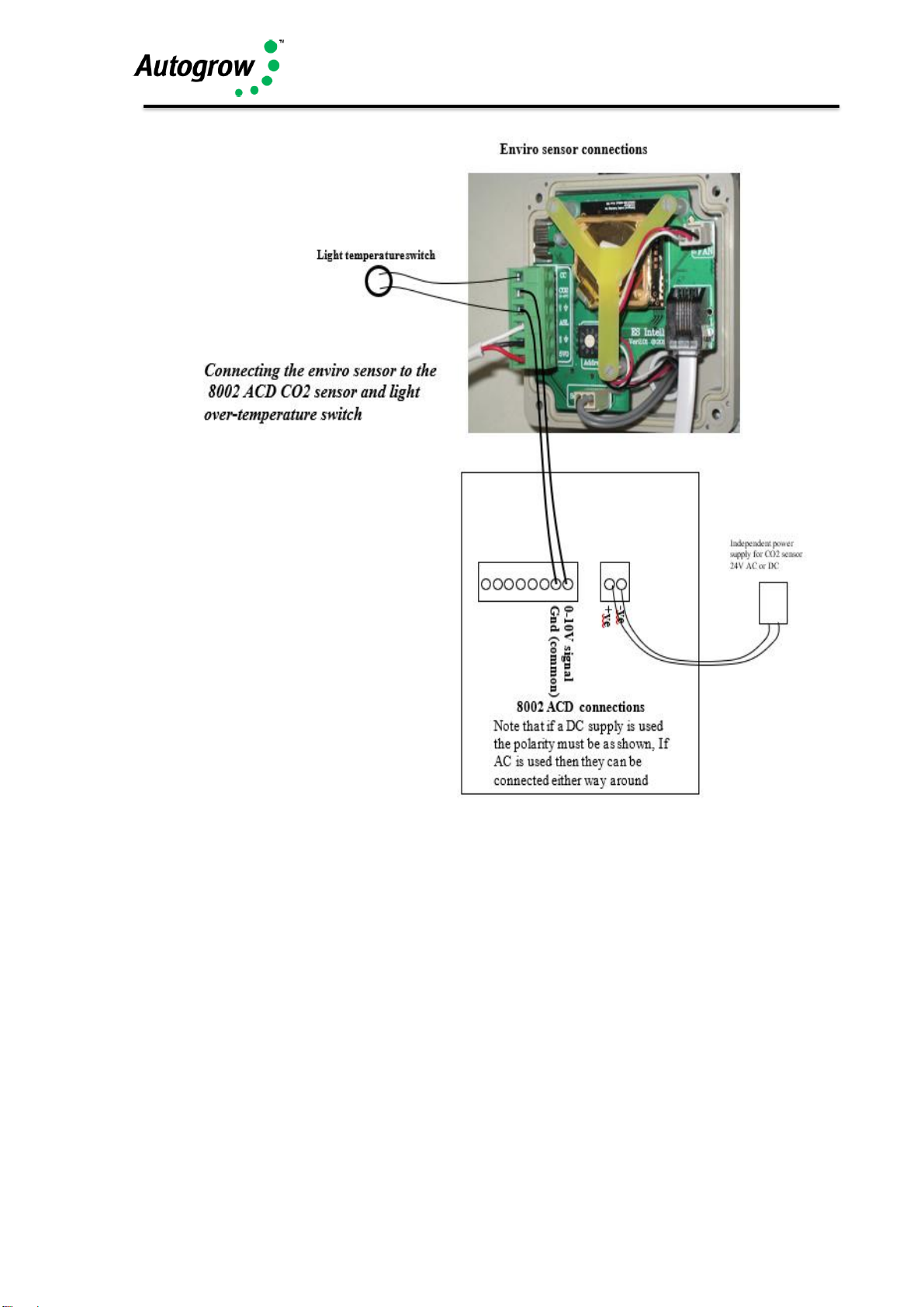
The modern louvred enviro sensors can be fitted with an internal CO2 sensor or
may use an external sensor (0..10V) if that is preferred (NOTE: Ultra edition can
only use internal CO2 sensors). The diagram above shows both methods. Note
that if a second enviro sensor is used it is not absolutely necessary for it to have a
second CO2 sensor although one may be fitted if desired and the controller will then
operate according to the average value from the two sensors. The external CO2
sensors require a low voltage power supply – normally 24V but the internal sensors
are powered directly over the normal 3/4-wire connection. The louvred type enviro
sensor may be connected using the supplied plug-in wiring or can also be hard
wired to the internal connector if that is desired.
To hardware to the enviro sensor and outside temp sensor, slide out the inner
plastic box after rotating the holding tabs to provide a clear exit path.
ES Intelli “Modern-louvred” model
IntelliClimat
Enviro sensor 1
Enviro sensor 2
CO2
externa
Outside
Double adapter
6 core phone
extension cable
Use the plug-in wiring supplied or hard wire if
preferred
Shown with CO2 sensor installed
secured with locking “Y” clip
Page 17

IntelliClimate Manual
©2018 Autogrow Systems Ltd V4.5 17
ES Intelli “Ultra” model
Ultra-edition must be hard-wired
Power +ve
Power –ve
GND (Black)
Page 18

IntelliClimate Manual
©2018 Autogrow Systems Ltd V4.5 18
ES Intelli “Ultra” wiring at Controller
Setting the address of the enviro sensors
The first enviro sensor should have the rotary switch set to 1 with the second enviro
sensor set to 2 and the outside temp sensor set to 0.
Light over-temperature sensor – CONNECT TO ENVIRO SENSOR 1
These are useful where air cooled lights are used so that if the light cooling fan fails
and the light fitting starts to overheat, the sensor contacts will open and the lights will
be turned off and the alarm triggered. Note that any thermostat type sensor can be
used providing its contacts are normally closed (when cool) and open when overtemperature.
It is preferable to use the type that stay open once tripped and need to be manually
reset.
Note that the over-temperature switch can only be connected to enviro sensor 1.
Page 19
IntelliClimate Manual
©2018 Autogrow Systems Ltd V4.5 19
Relay Boxes
To drive mains powered equipment, the 24V DC outputs must be connected to relays
or contactors that have 24V DC coils. We normally supply twin relay boxes that
provide a convenient method of achieving this.
Note that the total mains current draw from a relay box should not exceed the rating
as printed on its label.
Secure the Relay boxes to the wall. If using plaster board anchors, screw the anchors
in firmly until they are flush with the wall. The anchors supplied are self drilling and so
there is no need to pre-drill the wall. Just position them, give them a light tap to get
started and then turn to drill/screw in with a Phillips or Pozi screw driver. Use the
Page 20

IntelliClimate Manual
©2018 Autogrow Systems Ltd V4.5 20
longer metal screws to fix the valve plate to the nylon anchors or if fixing to a solid
wood back board, use the shorter screws supplied. A thin flexible cable is used to
connect the relay box to the controller. The black wire is the common, the red is for
the upper socket outlet and the white is for the lower socket outlet.
Example connection of a relay box to operate Light1 and Fan1
Page 21

IntelliClimate Manual
©2018 Autogrow Systems Ltd V4.5 21
Section D – Software installation
Please head to our online Help, found here: help.autogrow.com/intelligrow
Section E – Maintenance
Very little maintenance is required and is really limited to keeping all equipment clean,
dry and cool. Observe and double check all readings from time to time to ensure that
sensors are still accurate. This is particularly important for the CO2 sensor. The
recalibration procedure for the 8002 – ACD sensor is provided as appendix 1.
Section F - Fault finding
1) Unit is completely dead – i.e. no display, no power light and no outputs
Check that the power pack is functioning (by measuring with a voltmeter if
possible) and that it is plugged in, switched on and properly connected to the
controller. If the unit still fails to function then the probability is that the internal
4A fuse (20mm x 5mm miniature glass fuse) may have been blown. The most
likely cause of this happening is that wires connecting to the peripheral
equipment have touched together and shorted out. To fix this it is important to
clear the fault first. Inspect all wiring and ensure that all wires are well insulated
right to the point where they enter the connector. Also check the connections at
the relays or peripherals. Then replace the fuse with a genuine 4A fuse. DO
NOT ATTACH WIRE OR ALUMINIUM FOIL ACROSS IT.
2) Lights or other equipment do not come on when expected. Test the relevant
output using a voltmeter set on a range suitable for measuring 24V DC.
Measure between the output pin in question and one of the Common
connections. If the pin has 24V on it then the fault lies with the peripheral or
relay driving it. If there is not 24V on the relevant pin then recheck all settings
starting with configuration. If advanced settings have been changed then it may
be advisable to use the button at the bottom to restore then to factory defaults.
Finally, double check all other settings and readings to be absolutely sure that
the peripheral in question should be ON.
Page 22

IntelliClimate Manual
©2018 Autogrow Systems Ltd V4.5 22
Section G - Warranty
The warranty on the controller and environment sensor is limited to 2 years – return
to factory. Before returning the unit for service you must call Autogrow Systems Ltd
for a return authorization and the preservice check sheet must be completed.
The plug-in, easily replaceable, Temperature/RH sensors and any fans used carry a
12-month warranty.
This warranty specifically excludes any parts that have been broken or damaged by
water, chemical attack or excessive temperature. The controller and power adapter
must be stored and used in a dry, shaded and well-ventilated situation. At no time
must the case temperature be allowed to exceed 55 deg C (130 deg F).
This warranty expressly excludes liability for consequential damages or for charges
for labour or other expense in making repairs or adjustments, or loss of time or
inconvenience.
Page 23

IntelliClimate Manual
©2018 Autogrow Systems Ltd V4.5 23
Appendix 1 –
Calibration of Internal CO2 sensor (0-5000ppm)
The CO2 sensors which may be fitted inside the louvered type environment sensor
box are calibrated at the IntelliClimate controller as follows:
1) SOFT CALIBRATION – allows calibration against an accurate CO2
sensor or known CO2 level
On the IntelliClimate go enter the “Configure” menu and navigate to “Enviro
1 (or 2) CO2 Calib”. Place the sensor in a known CO2 concentration e.g.
outside in open air (CO2 = 380ppm) or else compare with another accurately
calibrated CO2 sensor.
When doing this try not to breath near the sensors and do not do this near
any other sources of CO2.
Use the up or down arrows to change the scaling away from the normal
100% scaling until the scaled or calibrated CO2 reading below the box is
correct and press “Save” to store the new calibration. When doing this the
percentage change needed is displayed on the screen. The normal
percentage is 100% and if this ever needs to be set below 50% or above
150% this may indicate some deterioration of the sensor. In this case first
try the hard calibration below to see if that corrects the reading. If not you
may require a new CO2 module.
2) HARD CALIBRATION – This allows the sensor to self-calibrate when
placed in fresh air at ambient CO2 levels. As this is less convenient
than the SOFT calibration mentioned above it is suggested that this is
carried out only once per year. NOTE THAT AFTER COMPLETING A
HARD CALIBRATION A SOFT CALIBRATION MUST ALSO BE CARRIED
OUT.
Place the sensor box outside in fresh air and connect to an IntelliClimate
controller. Navigate to, and enter, the Configure Menu. Navigate and enter
“CO2 configuration” then move down and enter “Open air configuration” then
press edit and a screen with instruction will appear. On pressing start a new
screen with a timer counting down from 11 minutes will appear. During this
time leave the enviro sensor in fresh air and avoid breathing near it. It will
self-calibrate to the ambient CO2 level. At the end of this navigate back to
the software calibration screen “CO2 scale factor” and set this to 100% i.e.
no scaling.
Page 24

IntelliClimate Manual
©2018 Autogrow Systems Ltd V4.5 24
Appendix 2 – Specification
Power supply adapter
The unit is normally supplied with a universal input (100V to 240V 50/60Hz) power
adapter which provides the IntelliClimate with a safe, low voltage supply of 24V DC
at 2.5Amps
Outputs
8 outputs that have the same voltage as the supply (normally 24V DC)
Ratings of individual outputs are 3Amps but of course the total draw from all 8
outputs must not exceed the rating of the supply adapter.
Inputs
The temperature, RH, Light sensors all connect on a bus cable. The three wires in
the bus cable supply the sensor units with 5VDC power and receive digital data
back along the third wire. Maximum length of this bus cable is 20m (60ft). The unit
is supplied with one temperature/RH/light sensor box on a 5m (15ft) cable. A
second sensor box and an external temperature sensor may be added. These
would be connected in daisy chain fashion on the single bus cable.
Temperature/RH/Light enviro sensors
Temperature accuracy +/- 0.5oC
RH accuracy +/- 3% to 95% then +/-5%
Light accuracy +/- 5%; Total light 0 to 1000Joules
CO2 input: 10-bit resolution (1 part in 1000)
CO2 sensor – Internal
0 to 5000ppm range. Either 1 or 2 of these may be installed and with 2 installed the
controller will work to the average of the two. Each CO2 sensor can be calibrated
separately – see appendix 1
3 x Relay Boxes
The twin relay boxes have a total current capability as follows:
USA 110V 15A total draw
UK 240V at 13A
Australasia 240V at 10A
Latest Manual
To access the latest version of your instruction manual, please head to
help.autogrow.com
Page 25
IntelliClimate Manual
©2018 Autogrow Systems Ltd V4.5 25
Thank you for your purchase.
Get the most out of your IntelliDose or IntelliClimate control systems with IntelliGrow.
IntelliGrow is a cloud-based solution allowing you to access, set, monitor and manage
your growing operation - anywhere, anytime.
Start your 14 day free trial at intelligrow.autogrow.com
Better growing control, more freedom. Manage
your growing
operation anywhere, anytime by
logging
in on your Mac, PC, tablet or phone.
Base today’s decisions on real-time data.
Leverage up to 5 years of historical grow data to
make smarter, data-driven decisions.
Best in class infrastructure. Protect
your
growing data with enterprise level
data security, at
small business prices.
Keep your site running smoothly. Invite
Autogrow’s experts to log in remotely when you
need them.
We’ll handle the tech. Seamless product updates
mean you get more
functionality, without any
disruption.
Don’t have an on-site
computer? IntelliLink
will provide the
internet connectivity
Find out more at autogrow.com/intelligrow
Page 26

IntelliClimate Manual
©2018 Autogrow Systems Ltd V4.5 26
Page 27

IntelliClimate Manual
©2018 Autogrow Systems Ltd V4.5 27
Page 28

IntelliClimate Manual
©2018 Autogrow Systems Ltd V4.5 28
In the box:
HCTR-IC-001-01
1 x IntelliClimate controller
1 x Mounting hardware
1 x Instruction manual
HKIT-IC-001-01
1 x IntelliClimate controller
1 x 24V DC 2.5A power supply with universal plug
1 x EnviroSensor (temperature, humidity, light, CO2)
1 x 3m USB cable
1 x Magnetic door switch
1 x Mounting hardware
1 x Instruction manual
2-Year-Warranty
To obtain our warranty service, please do either one of the following:
•
Register online at www.autogrow.com/warranty-registration
•
Contact the distributor you bought the product from.
autogrow.com
sales@autogrow.com
North America (+1) 707 206 2220
Global (+64) 9 415 2380
 Loading...