


Mk8 MM
End User Guide

Mk8 MM
End User Guide
Issued by:
AUTOFLAME ENGINEERING LTD
Unit 1-2, Concorde Business Centre
Airport Industrial Estate, Wireless Road
Biggin Hill, Kent TN16 3YN
Tel: +44 (0)845 872 2000
Fax: +44 (0)845 872 2010
Email: salesinfo@autoflame.com
Website: http://www.autoflame.com/
Registered Holder:
Company:
Department:
This manual and all the information contained herein is copyright of
Autoflame Engineering Ltd. It may not be copied in the whole or part without
the consent of the Managing Director.
Autoflame Engineering Ltd’s policy is one of continuous improvement in both
design and manufacture. We therefore reserve the right to amend
specifications and/or data without prior notice. All details contained in this
manual are correct at the time of going to print.

Important Notes
A knowledge of combustion related procedures and commissioning is essential before
embarking work on any of the M.M./E.G.A. systems. This is for safety reasons and
effective use of the M.M./ E.G.A. system. Hands on training is required. For details on
schedules and fees relating to group training courses and individual instruction, please
contact the Autoflame Engineering Ltd. offices at the address listed on the front.
Short Form - General Terms and Conditions
A full statement of our business terms and conditions are printed on the reverse of all
invoices. A copy of these can be issued upon application, if requested in writing.
The System equipment and control concepts referred to in this Manual MUST be installed,
commissioned and applied by personnel skilled in the various technical disciplines that
are inherent to the Autoflame product range, i.e. combustion, electrical and control.
The sale of Autoflame’s systems and equipment referred to in this Manual assume that
the dealer, purchaser and installer has the necessary skills at his disposal. i.e. A high
degree of combustion engineering experience, and a thorough understanding of the
local electrical codes of practice concerning boilers, burners and their ancillary systems
and equipment.
Autoflame’s warranty from point of sale is two years on all electronic systems and
components.
One year on all mechanical systems, components and sensors.
The warranty assumes that all equipment supplied will be used for the purpose that
it was intended and in strict compliance with our technical recommendations. Autoflame’s warranty and guarantee is limited strictly to product build quality, and design.
Excluded absolutely are any claims arising from misapplication, incorrect installation
and/or incorrect commissioning.

Contents
1 OVERVIEW AND BENEFITS……………………………………………………………………………… 1
1.1 Features and Benefits…………………………………………………………………………………………… 1
1.2 System Example…………………………………………………………………………………………………… 4
1.3 Micro-Modulation (MM)………………………………………………………………………………………. 5
2 ELECTRICAL SPECIFICATIONS………………………………………………………………………….. 6
2.1 Classifications………………………………………………………………………………………………………. 6
2.2 Inputs and Outputs………………………………………………………………………………………………. 6
2.3 Cable Specifications……………………………………………………………………………………………… 8
3 END USER OPERATION…………………………………………………………………………………… 9
3.1 Home Screen…………………………………………………………………………………………………… 9
3.1.1 Home Screen Components……………………………………………………………………… 10
3.1.2 Faults……………………………………………………………………………………………………… 12
3.2 Status Screen…………………………………………………………………………………………………. 13
3.2.1 Status………………………………………………………………………………………………………13
3.2.2 Status – History………………………………………………………………………………………. 14
3.2.3 Status – Burner Enable/Disable……………………………………………………………… 15
3.2.4 Status – Low Flame Hold………………………………………………………………………… 16
3.2.5 Status – Hand Mode………………………………………………………………………………..17
3.3 Fuel-Air Screen……………………………………………………………………………………………… 18
3.3.1 Fuel-Air – Curve……………………………………………………………………………………… 18
3.3.2 Fuel-Air – Map……………………………………………………………………………………….. 19
3.3.3 Fuel-Air – History……………………………………………………………………………………. 20
3.4 Flame Safeguard Screen………………………………………………………………………………….21
3.4.1 Flame Safeguard…………………………………………………………………………………….. 21
3.4.2 Flame Safeguard – History……………………………………………………………………… 22
3.5 Channels Screen…………………………………………………………………………………………….. 23
3.5.1 Servomotor…………………………………………………………………………………………… 23
3.5.2 VSD Channel…………………………………………………………………………………………. 24

3.6 Gas Pressure Sensor Screen 35 3.6.1 Gas Pressure…………………………………………. 25
3.6.2 Gas Sensor – History………………………………………………………………………………. 26
3.7 Air Pressure Sensor Screen……………………………………………………………………………. 27
3.7.1 Air Pressure……………………………………………………………………………………………. 27
3.7.2 Air Sensor – History………………………………………………………………………………… 28
3.8 First Outs………………………………………………………………………………………………………..29
3.9 System Configuration Screen…………………………………………………………………………. 30
3.9.1 Language Selection…………………………………………………………………………………. 31
3.9.2 Options……………………………………………………………………………………………………32
3.9.3 Parameters…………………………………………………………………………………………… 33
3.9.4 Expansion Options…………………………………………………………………………………..34
3.9.5 Set Clock………………………………………………………………………………………………….35
3.9.6 Manual…………………………………………………………………………………………………… 36
3.9.7 Commission Data……………………………………………………………………………………. 37
3.9.8 Diagnostics ……………………………………………………………………………………………. 38
3.9.9 System Log……………………………………………………………………………………………… 39
4 ERRORS AND LOCKOUTS……………………………………………………………………………… 40
4.1 Errors…………………………………………………………………………………………………………………. 40
4.2 Lockouts………………………………………………………………………………………………………………44
4.3 Alarms and Warnings…………………………………………………………………………………………. 49
4.4 Settings Conflicts………………………………………………………………………………………………… 57
4.5 Forced Commission Reasons………………………………………………………………………………. 62
4.6 Troubleshooting and Further Information…………………………………………………………… 64
4.6.1 UV Shutter Faults………………………………………………………………………………………… 64
4.6.2 UV Problems……………………………………………………………………………………………….. 64
4.6.3 Snubbers…………………………………………………………………………………………………….. 64
4.6.4 Channel Positioning Error……………………………………………………………………………. 65
4.6.5 Input Fault…………………………………………………………………………………………………… 65
6 STANDARDS…………………………………………………………………………………………………. 66

1 Overview and Benefits
22.05.2017 Mk8 MM End User Guide Page 1
1 OVERVIEW AND BENEFITS
1.1 Features and Benefits
Micro-Modulation (MM) / Flame Safeguard
Fuel/ air ratio control
Full colour touch screen
120V or 230V standard operation 50/60Hz
Controls up to 5 servomotors and 2 variable speed drives (VSD/ VFD)
4 independent fuel programmes
Fully adjustable PID load control for temperature or pressure
Internal flame safeguard – full flame supervision with self-check UV or IR
Dual flame scanner operation (IR and UV scanners)
Gas valve train leak supervision and high/low gas pressure monitoring
Air pressure proving and monitoring
128 lockouts, errors, alarms and warnings stored with date, time, phase and reset
1000 entry system log stored with date, time and status
Online diagnostics showing system electronics information
Single point change for adding, removing and adjusting fuel/air positions on fuel-air curve
Golden start position for optimum ignition position
Flue gas recirculation start position
Variable servomotor travel speed
Burner control safety times user selectable
External voltage/current load control and setpoint adjustment
Outside temperature compensation of boiler setpoint
Second setpoint and run times scheduling
Hand/auto/low flame hold firing modes
Various boiler load detectors available
Fuel flow metering capability – instantaneous and totalised
Fuel flow feedback
Multi-burner capability with synchronised firing rate up to 10 MMs
4-20mA (0-20mA) / 0-10V (2-10V) input for external modulation
4-20mA (0-20mA) / 0-10V (2-10V) output confirming firing rate
Fully metered combustion control for commissioning based on equivalence ratio and excess air
Draft control to maintain stack pressure
Password protection of all safety related functions
Infra-red port for upload/download of commission data

1 Overview and Benefits
Page 2 Mk8 MM End User Guide 22.05.2017
15 First out annunciation inputs
4 fuel commission curves possible
24 hour history graphical information on MM when powered on
Custom boiler display configuration
Water Level Control
Fully modulating feed water control with servomotor and VSD as well pump on/off
Capacitance probes for patented wave signature level detection
Water level alarms 2
nd
low, 1st low, high water and optional pre 1st low and pre-high water
Conductivity probe for auxiliary 2
nd
low alarm
Automatic bottom blowdown with time reduction for blowdown savings
Continuous modulating top blowdown control to maintain TDS in water
Steam/ hot water flow metering to calculate flow rates based on temperature sensor
Exhaust Gas Analyser (EGA)
3 Parameter trim of O
2, CO2 and CO
Analysis of O
2, CO, CO2, NO, exhaust gas temperature, efficiency and delta temperature
Optional analysis of NO
2 and SO2
Local display for re-calibration, changing cells, user configuration and standalone operation
Upper/lower offset and absolute limits for O
2, CO, CO2, NO and exhaust gas temperature
Six 4-20mA output signal for interface with other controls/chart recorders
Intelligent Boiler Sequencing
System will sequence hot water boilers or steam boilers via lead/lag distribution
Fully adjustable user options within the system to tailor sequencing operation to the application
System control for isolation of valves or pumps (2 port valve operation)
Standby setpoint and warming for lag boilers via a standby pressure and timing sequence
Lead boiler and lag boiler warming modes selection
Remote Control and Data Transfer Interface (DTI)
Direct Modbus communications from MM including remote setpoint and firing rate adjustment,
burner enable/disable (without DTI or intelligent boiler sequencing)
DTI will collect operational data for up to 10 MM modules, 10 EGA modules and 10 universal
I/O modules in one communications loop
Information transmitted via RS422 or Ethernet link to local PC/network for running Autoflame
CEMS Audit software

1 Overview and Benefits
22.05.2017 Mk8 MM End User Guide Page 3
PC Compatible
Download all commissioning data and controller settings from MM module to a PC
Upload commission data and controller settings from PC to MM module
Universal Digital and Analogue Input/ Output Module
Detailed logging inputs and outputs when coupled with Mk7 DTI
16 Line voltage inputs (110V/ 230V)
6 Analogue inputs and 6 analogue outputs
8 Volt free contacts
Configurable alarms through Mk7 DTTI
1 Overview and Benefits
Page 4 Mk8 MM End User Guide 22.05.2017
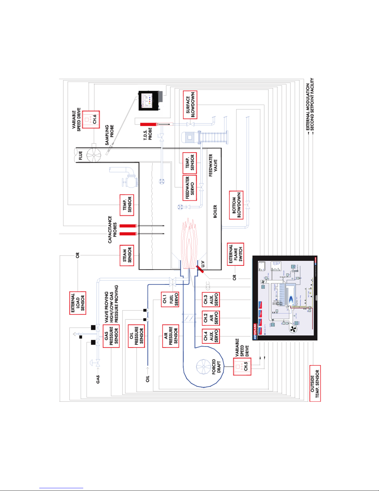
1.2 System Example

1 Overview and Benefits
22.05.2017 Mk8 MM End User Guide Page 5
1.3 Micro-Modulation (MM)
To ensure maximum efficiency and reliability of the boiler plant operation, two requirements are of
paramount importance, the air to fuel ratio and the target temperature or pressure:
The air to fuel ratio must be kept to the minimum to ensure complete combustion within the
limitations of the combustion head design. A very high air to fuel ratio will be an indication of
high excess air, which decreases the overall efficiency of the boiler. The fuel valve and air
damper positions set for this minimum air to fuel ratio along the whole commission curve must
be infinitely repeatable to an incredibly high degree of accuracy.
The target temperature or pressure of the boiler should be monitored by the combustion system
and at all times, with exactly the right amount of fuel and air fired to achieve this target value.
Irrespective of load changes, the burner/boiler system should be able to meet the target
temperature or pressure.
The burner’s fuel to air ratio was traditionally governed by mechanical systems which involved multiple
cams, shafts and linkages controlled by one motor. The inherent hysteresis that occurred from the
system design allowing components to be loose, which made the level of accuracy required impossible.
With this poor accuracy, the response of the fuel input to the monitored temperature/ pressure of the
boiler meant that the set target value at most times would overshoot or fall short.
The Micro-Modulation module is the basic building block of the Autoflame System. The Autoflame MM
module provides an easily programmable and flexible means of optimising combustion quality
throughout the load requirement range of the burner/boiler unit whilst ensuring the temperature is
accurate to within 1°C (°F) and pressure to within 1 PSI (0.1Bar). Using direct drive motors to
individually control the air damper and fuel valve(s), gives the optimum combustion of the burner at
every point along the firing range. The allowed error in angular degrees of rotation between the two
servomotors at any position in the load range is 0.1°.
This automated system of burner control can achieve ‘locked on’ near stoichiometric air to fuel mixing
throughout the fuel input range of the boiler while maintaining exact temperature or pressure target
values. The load control incorporates user-variable Proportional Integral Derivative control. The PID
control is infinitely adjustable to match any boiler room requirements.

2 Electrical Specifications
2 ELECTRICAL SPECIFICATIONS
2.1 Classifications
Classification according to BS EN298:2012
Mains
Supply:
Single phase 230V, +10%/-15%}
47-63 Hz, unit max. consumption 140W
Single phase 120V, +10%/-15%}
Climate: Min. Temperature 0
O
C (32OF)
Recommended Temperature Less than 40
O
C (104OF)
Max. Temperature 60
O
C (140OF)
Humidity 0 to 90% non-condensing
Storage: Temperature -20 to 85
O
C (-4 to 185OF)
Protection
Rating:
The unit is designed to be panel mounted in any orientation and the front facia is IP65,
NEMA4. The back of the unit is IP20, NEMA1.
2.2 Inputs and Outputs
MM Inputs and Outputs
230V Unit:
Outputs Terminal 57 250mA Must be connected through contactor
Max Load 6A
58 250mA Must be connected through contactor
59 1A 0.6 power factor
60 1A 0.6 power factor
61 1A 0.6 power factor
62 1A 0.6 power factor
63 1A 0.6 power factor
78 100mA To drive relay only – switched neutral
79 100mA To drive relay/lamp only – switched neutral
120V Unit:
Outputs Terminal 57 250mA Must be connected through contactor
Max Load 6A
58 250mA Must be connected through contactor
59 2A 0.6 power factor
60 2A 0.6 power factor
61 2A 0.6 power factor
62 2A 0.6 power factor
63 2A 0.6 power factor
78 100mA To drive relay only – switched neutral
79 100mA To drive relay/lamp only – switched neutral
22.05.2017 Mk8 MM End User Guide Page 6

2 Electrical Specifications
Expansion Board Inputs and Outputs
Outputs: 120/230 V All outputs with the exception of PF are switched neutrals
BFW 250mA Must be connected through contactor
BB 250mA Must be connected through contactor
HWV 100mA (alarm indicator)
2LA 100mA (alarm indicator)
2LV 100mA (alarm indicator)
H1A 100mA (alarm indicator)
1LV 100mA (alarm indicator)
79 100mA (alarm indicator on MM board)
TB 250mA Solenoid only, must be connected through contactor
PF Maximum 2A (load currents for above terminals)
Note: Max number of alarm indicators on at any time is 3 (1LV, 2LA, 2LV)
Main Voltage Signal Inputs:
At 120V current loading is approximately maximum 0.7mA per input.
At 230V current loading is approximately maximum 1.5mA per input.
Note:
1. The high and low voltage connections are not safe to touch. Protection against electric shock is
provided by correct installation. CAUTION – ELECTRIC SHOCK HAZARD.
2. Control voltage cabling should be maximum 10m, screened (if not screened then less than 1m,
however servomotors can be unscreened up to 10m)
3. Any cabling over 10m must have additional surge protection.
4. Low voltage cables should be screened cable as specified in section 2.3.
5. The burner ‘High Limit Stat’ must be a manual reset type.
Note: There is a lid (back plate) fitted onto the back of the Mk8 MM with a Warning label to prevent
any unauthorised fuse replacements.
Page 7 Mk8 MM End User Guide 22.05.2017

2 Electrical Specifications
2.3 Cable Specifications
Low Voltage
The screened cable used for low voltage wiring from the MM to the servomotors, detectors and
variable speed drive must conform to the following specification:
U.V. cable length should not exceed 25m, all other screened cable should not exceed 50m.
16/0.2mm PVC insulated overall braid, screened, PVC sheathed.
Sixteen wires per core
Diameter of wires in each core 0.2mm
Rated at 440V AC rms at 1600Hz
DEF 61-12 current rating per core 2.5A
Maximum operating temperature 70
o
C (158oF)
Nominal conductor area 0.5sq mm per core
Nominal insulation radial thickness on core 0.45mm
Nominal conductor diameter per core 0.93mm
Nominal core resistance at 20
o
C. 40.1Ω/1000m
Nominal overall diameter per core 1.83mm
Fill factor of braid screen 0.7
Equivalent imperial conductor sizes 14/0.0076
Use the number of cores suitable for the application. A universal part numbering system appears to
have been adopted for this type of cable as follows:
16-2-2C 2 Core
16-2-3C 3 Core
16-2-4C 4 Core
16-2-6C 6 Core
16-2-8C 8 Core
(5 Core not readily available)
Note: If using 4 Core cable and interference is detected, use 2 sets of 2 Core.
Data Cable
Data cable must be used for communication connections between MMs for sequencing applications as
well as between MMs to EGAs, MMs to a DTI and DTI to BMS systems.
Communication cable should not exceed 1km.
Types of data cable that can be used:
1 Beldon 9501 for 2-core shielded cable (1 twisted pair)
2 Beldon 9502 for 4-core shielded cable (2 twisted pairs)
3 STC OS1P24
Samples are available upon request. Low voltage and data cable can be ordered directly from
Autoflame Engineering, please contact Autoflame Sales.
When using a VSD, please review the manufacturer’s guidelines on installations to prevent EMC
including the recommendations for reactors and filters.
22.05.2017 Mk8 MM End User Guide Page 8

3 End User Operation
3 END USER OPERATION
3.1 Home Screen
Figure 3.1.i Home Screen
The home screen shown in Figure 3.1.i displays the current boiler setup. It provides operation
information for each component of the burner/boiler in real time. Pressing on components will display
further information e.g. pressing on the servomotor image will show the servomotor position history.
This boiler room setup can be configured to display what is actually on site, please see section 3.19.5
Boiler Room Configuration.
22.05.2017 Mk8 MM End User Guide Page 9

3 End User Operation
3.1.1 Home Screen Components
Servomotor Variable
speed drive
Flame
scanner
Oil pressure
sensor
Air pressure
sensor/
boiler steam
pressure
detector
Gas pressure
sensor
Boiler
temperature
detector/
outside
temperature
sensor
Feed water
temperature
sensor
Main fuel
valve open
Main fuel
valve closed
Pilot gas
valve open
Pilot gas
valve closed
Control fuel
valve open
Control fuel
valve closed
Main gas
regulator
Pilot gas
regulator
Gas flowing
No gas
flowing
Oil flowing
No oil
flowing
Combustion
air fan
Induced
draught fan
Gas flame Oil flame
#
Capacitance
probes
2
nd
Low
conductivity
probe
External level
sensor for
water level
Steam
header
TDS probe Feed water
pump
Page 10 Mk8 MM End User Guide 22.05.2017

3 End User Operation
IBS
Information
Three Pass
Fire Tube
22.05.2017 Mk8 MM End User Guide Page 11

3 End User Operation
3.1.2 Faults
Figure 3.1.2.i Lockouts
Press in the Home screen to view the faults, which are categorised into lockouts, errors,
alarms, warning and first out alarms, and are access by pressing on the corresponding tabs.
Fault Type Shuts Down Burner Reset By
Lockout Burner control fault Yes Reset button or input on T56
Error Internal or hardware fault Yes Power cycle
Alarm Critical system fault Yes Reset button or input
Warning Non-critical fault No Reset button
First out Configurable fault Optional Reset button/ auto
Page 12 Mk8 MM End User Guide 22.05.2017

3 End User Operation
3.2 Status Screen
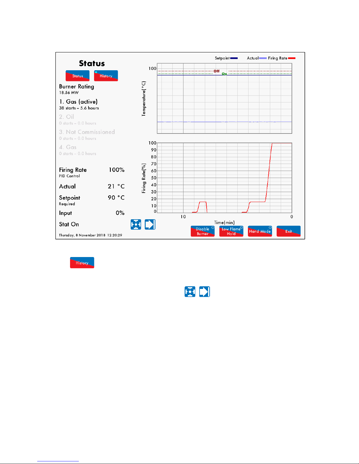
3.2.1 Status
Figure 3.2.1.i Status
Press on the boiler load detector or the boiler image in the Home screen (Figure 3.1.i) to display the
Status screen, which gives the following information:
Burner rating
Current fuel selected and type
Burner starts and run hours
Current firing rate
Control method – internal PID control, external modulation or DTI/remote firing rate
Actual temperature/pressure reading from load detector
Current setpoint – required, reduced, DTI or external
Stat status – running interlock T53/ internal stat
Burner switch on/off offset
Reduced setpoint
Indication if MM is firing to meet required or reduced setpoint (red = active, grey = inactive)
Arrows for adjusting setpoint
Press the arrows to change the required or reduced setpoints. If these arrows are not
displayed, then either the user setpoint change has been disabled (option 15), the DTI is controlling the
setpoint (option 16), external setpoint is enabled (parameter 72), or OTC is enabled (option 80).
Note: Use parameters 29 and 30 to adjust the load detector reading if required.
22.05.2017 Mk8 MM End User Guide Page 13
3 End User Operation
3.2.2 Status – History
Figure 3.2.2.i Status – History
Press in the Status screen in Figure 3.2.1.i to show the Status History. The setpoint, actual
temperature/pressure and firing rate are displayed graphically.
This data is logged for 24 hours on the MM. Use the buttons to change the timescale of the
data displayed, and press and drag on the axis to zoom in/out of the graph.
This information is logged for 2 years on the DTI when connected with the MM.
Note: Power cycling the MM or changing fuel will reset the 24 hour history data log on the MM.
Page 14 Mk8 MM End User Guide 22.05.2017

3 End User Operation
3.2.3 Status – Burner Enable/Disable
Figure 3.2.3.i Status – Burner Enable/Disable
Press and hold for 3 seconds in the Status screen in Figure 3.2.1.i to disable the burner.
Press and hold this same button to enable the burner.
22.05.2017 Mk8 MM End User Guide Page 15

3 End User Operation
3.2.4 Status – Low Flame Hold
Figure 3.2.4.i Status – Low Flame Hold
Press and hold for 3 seconds in the Status screen in Figure 3.2.2.i to put the MM in low
flame hold. Press and hold this button again to return to normal modulation.
Alternatively, the Mk8 MM can also be put in low flame hold via an input on terminal 95.
If low flame hold or hand mode is selected on the MM screen, this will override an input made on
terminal 94 or 95.
Note: If using intelligent boiler sequencing, then putting the MM into low flame hold will remove the
MM from the sequence loop. It will resume sequencing once low flame hold is deselected and after the
next scan time elapses.
Note: If low flame hold and hand mode are both selected, then hand mode takes priority.
Page 16 Mk8 MM End User Guide 22.05.2017
3 End User Operation
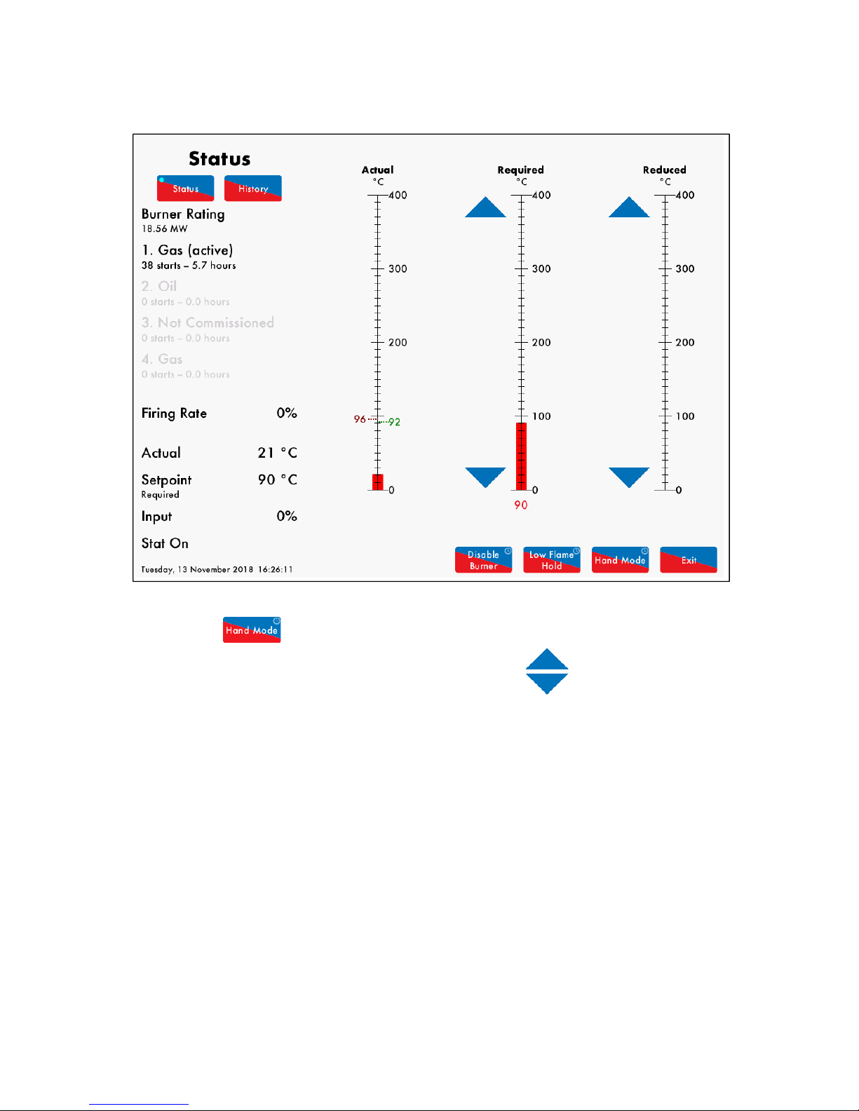
3.2.5 Status – Hand Mode
Figure 3.2.5.i Status – Hand Mode
Press and hold for 3 seconds in the Status screen in Figure 3.2.1.i to put the MM into hand
mode, where the firing rate can be driving up or down by using the arrows.
Alternatively, the MM can be put into hand mode by an input on terminal 94.
If low flame hold or hand mode is selected on the MM screen, this will override an input made on
terminal 94 or 95.
Note: If using intelligent boiler sequencing, then putting the MM into hand mode will remove the MM
from the sequence loop. It will resume sequencing once hand mode is deselected and after the next
scan time elapses.
Note: If low flame hold and hand mode are both selected, then hand mode takes priority.
Note: If a firing rate limit is set (option 66), then the firing cannot be driven past this in hand mode.
22.05.2017 Mk8 MM End User Guide Page 17
3 End User Operation
3.3 Fuel-Air Screen
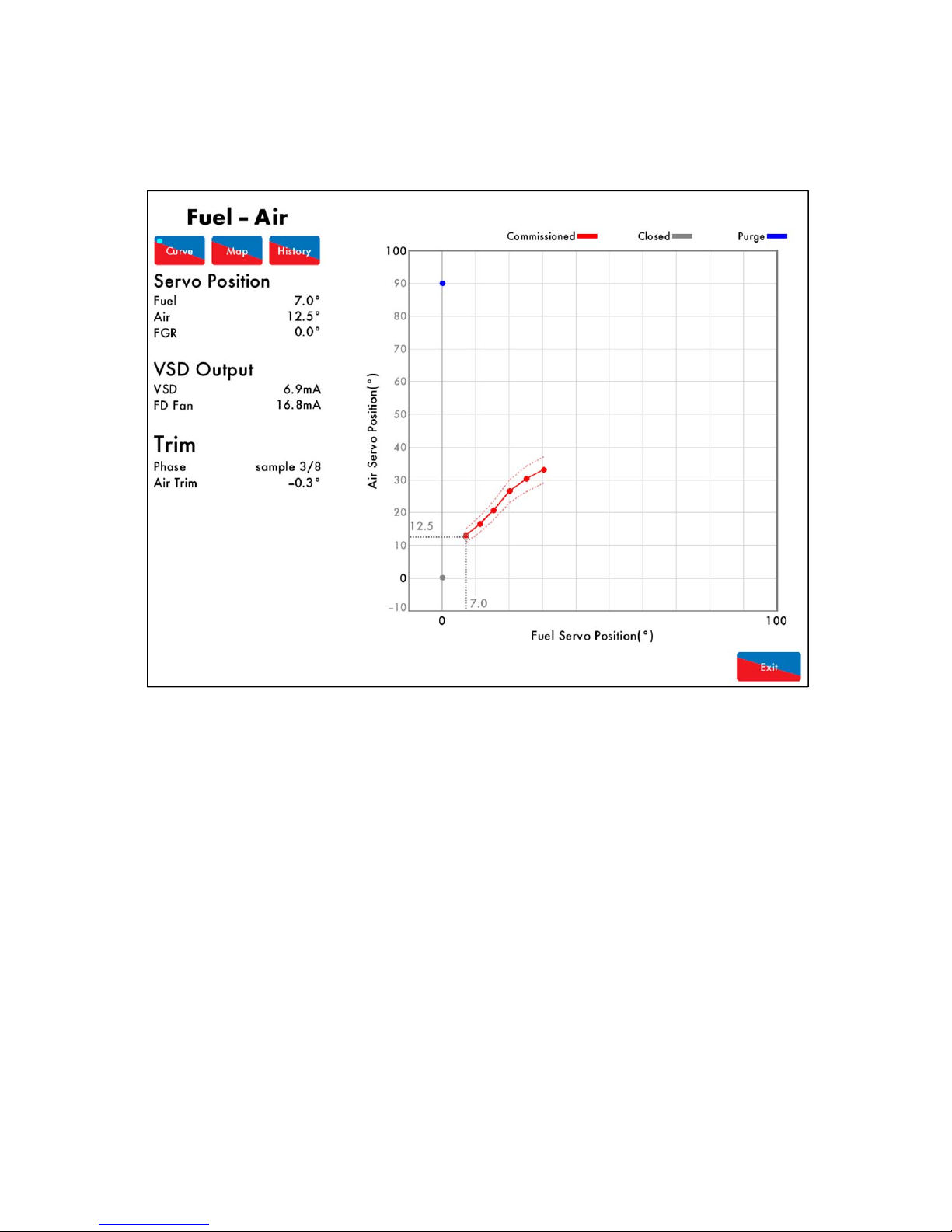
3.3.1 Fuel-Air – Curve
Figure 3.3.1.i Fuel-Air – Curve
Press the flame in the Home screen in Figure 3.1.i to view the Fuel-Air screen, which shows current
servomotor and VSD output positions, the trim status and the commission curve graph.
Page 18 Mk8 MM End User Guide 22.05.2017
3 End User Operation
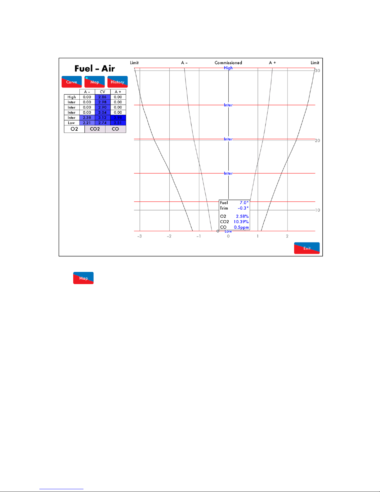
3.3.2 Fuel-Air – Map
Figure 3.3.2.i Fuel-Air – Map
Press in the Fuel-Air screen in Figure 3.3.1.i to view the commissioned trim values if an EGA
has been enabled with trim. The air rich (A+) and fuel rich (A-) values are shown for each
commissioned point on the fuel-air curve, for the O
2
, CO and CO2. The graph shows the EGA’s current
readings and if there is any trim correction on the air damper. The circle on the fuel-air map indicates
the current position of the trim correction, and how far the current combustion values are from the
commissioned values.
Note: Option 12 must be set to 2 or 3 for the 3-parameter trim function to be activated.
22.05.2017 Mk8 MM End User Guide Page 19
3 End User Operation
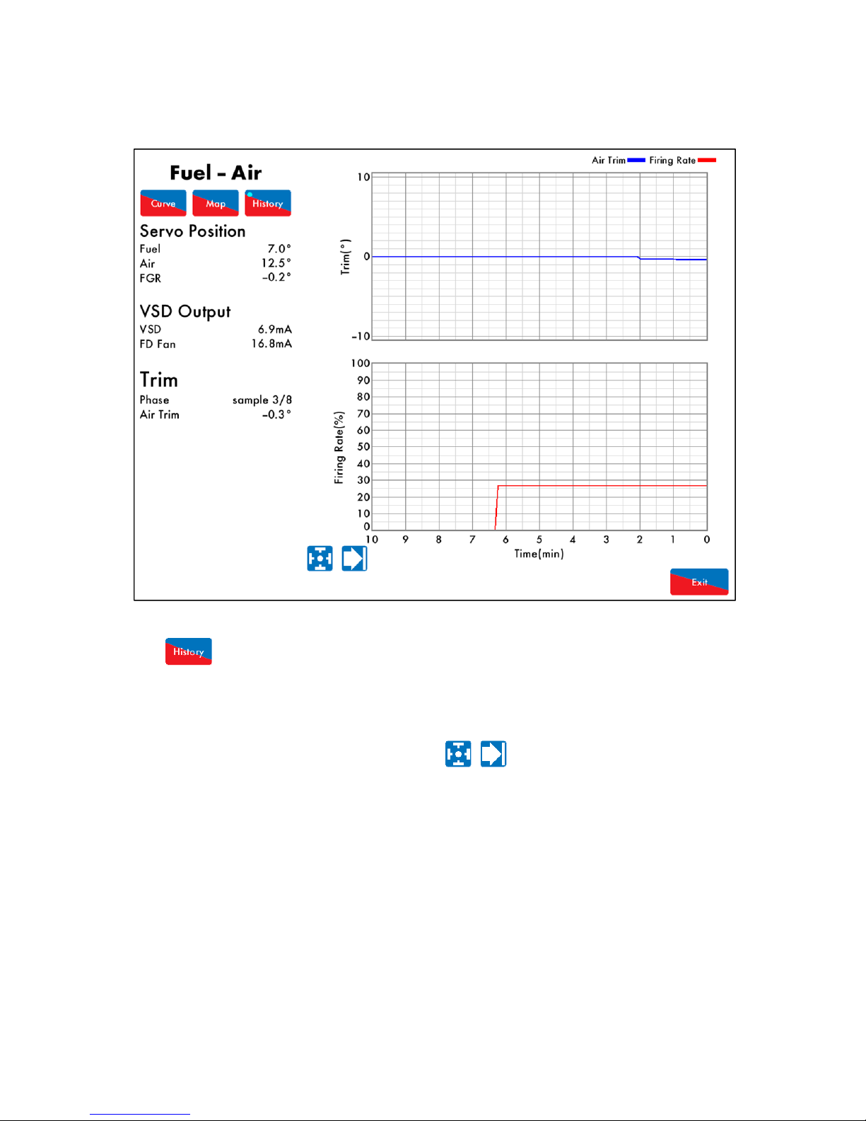
3.3.3 Fuel-Air – History
Figure 3.3.3.i Fuel-Air – History
Press in the Fuel-Air screen in Figure 3.3.1i to view the Fuel-Air History screen, which shows the
firing rate and air trim history.
Note: Option 12 must be set to 2 or 3 for the 3-parameter trim function to be activated.
This data is logged for 24 hours on the MM. Use the buttons to change the timescale of the
data displayed, and press and drag on the axis to zoom in/out of the graph.
This information is logged for 2 years on the DTI when connected with the MM.
Note: Power cycling the MM or changing fuel will reset the 24 hour history data log on the MM.
Page 20 Mk8 MM End User Guide 22.05.2017

3 End User Operation
3.4 Flame Safeguard Screen
3.4.1 Flame Safeguard
Figure 3.4.1.i Flame Safeguard
Press on the flame scanner in the Home scree in Figure 3.1.i to view the Flame Safeguard screen,
which shows the current firing phase of the MM, pilot type and flame scanner signal strength.
Throughout the entire burner start-up and firing sequence, the vertical dotted line will move horizontally
showing which phase the burner is at currently. The rows refer to:
Post purge
Pre purge
Air damper position
Main fuel valve
Pilot fuel valve
Ignition
Blower motor
Note: If a flame switch is used for flame detection, then flame switch show as either on (flame
detected) or off (no flame detected).
Please refer to section XX for the start-up sequence of the burner.
22.05.2017 Mk8 MM End User Guide Page 21

3 End User Operation
3.4.2 Flame Safeguard – History
Figure 3.4.2.i Flame Safeguard - History
Press in the Flame Safeguard screen in Figure 3.4.1.i to view the Flame Safeguard History,
showing the flame scanner signal and firing rate.
This data is logged for 24 hours on the MM. Use the buttons to change the timescale of the
data displayed, and press and drag on the axis to zoom in/out of the graph.
This information is logged for 2 years on the DTI when connected with the MM.
Note: Power cycling the MM or changing fuel will reset the 24 hour history data log on the MM.
Page 22 Mk8 MM End User Guide 22.05.2017

3 End User Operation
3.5 Channels Screen
3.5.1 Servomotor
Figure 3.5.1.i Servomotor
Press on a servomotor in the Home screen in Figure 3.1.i to view the Channels screen, which shows the
current servomotor positions and VSD outputs and inputs.
This data is logged for 24 hours on the MM. Use the buttons to change the timescale of the
data displayed, and press and drag on the axis to zoom in/out of the graph.
This information is logged for 2 years on the DTI when connected with the MM.
Note: Power cycling the MM or changing fuel will reset the 24 hour history data log on the MM.
22.05.2017 Mk8 MM End User Guide Page 23

3 End User Operation
3.5.2 VSD Channel
Figure 3.5.2.i VSD Channel
Press or in the Channels screen in Figure 3.5.1.i to view the VSD Channel 5 or
VSD Channel 6 output and input history, respectively. Alternatively, pressing on the VSD in the Home
screen in Figure 3.1.i will also display the VSD Channel screen.
This data is logged for 24 hours on the MM. Use the buttons to change the timescale of the
data displayed, and press and drag on the axis to zoom in/out of the graph.
This information is logged for 2 years on the DTI when connected with the MM.
Note: Power cycling the MM or changing fuel will reset the 24 hour history data log on the MM.
Page 24 Mk8 MM End User Guide 22.05.2017

3 End User Operation
3.6 Gas Pressure Sensor Screen
3.6.1 Gas Pressure
Figure 3.6.1.i Gas Pressure
Press on the gas pressure sensor (if enabled) in the Home screen in Figure 3.1.i to view the gas
pressure screen, which shows the following information:
Commissioned gas pressure for the corresponding point on fuel-air curve
Actual (current) gas pressure
Valve proving gas pressure
Status of main gas and vent valves
Upper/lower offset gas pressure limits for fuel-air curve
22.05.2017 Mk8 MM End User Guide Page 25

3 End User Operation
3.6.2 Gas Sensor – History
Figure 3.6.2.i Gas Sensor – History
Press in the Gas Pressure screen in Figure 3.6.1.i to view the Gas Pressure History screen,
showing the commissioned and actual gas pressure histories.
This data is logged for 24 hours on the MM. Use the buttons to change the timescale of the
data displayed, and press and drag on the axis to zoom in/out of the graph.
This information is logged for 2 years on the DTI when connected with the MM.
Note: Power cycling the MM or changing fuel will reset the 24 hour history data log on the MM.
Page 26 Mk8 MM End User Guide 22.05.2017

3 End User Operation
3.7 Air Pressure Sensor Screen
3.7.1 Air Pressure
Figure 3.7.1.i Air Pressure
Press on the air pressure sensor in the Home screen in Figure 3.1.i to view the Air Pressure screen,
which shows the expected air pressure, actual (current) air pressure and the difference between these
values, for the corresponding point on the fuel-air curve.
The graph shows the commissioned air pressure for the fuel-air curve and the upper/lower offset limits,
as well as the air pressure values with trim function enabled on the air damper.
If commissioned with an EGA, the air pressure is stored during the commissioning the trim function, and
shown as the red line on the graph.
22.05.2017 Mk8 MM End User Guide Page 27

3 End User Operation
3.7.2 Air Sensor – History
Figure 3.7.2.i Air Sensor – History
Press in the Air Pressure screen in Figure 3.7.1.i to view the Air Pressure History screen,
showing the commissioned and actual air pressure histories.
This data is logged for 24 hours on the MM. Use the buttons to change the timescale of the
data displayed, and press and drag on the axis to zoom in/out of the graph.
This information is logged for 2 years on the DTI when connected with the MM.
Note: Power cycling the MM or changing fuel will reset the 24 hour history data log on the MM.
Page 28 Mk8 MM End User Guide 22.05.2017

3 End User Operation
Outs
Figure 3.17.i First Outs
Press (if enabled) in the Home Screen in Figure 3.1.i to view the First Outs screen. The
functions of a first out when active is summarised below:
Function When Active Description
Disabled Does not function.
Monitor Burner continues firing, but the events will be logged.
Non-recycle Burner stops firing and the first out must be reset for the burner to restart.
Recycle Burner stops firing and restarts automatically when the input state changes.
Stop EGA Sampling Burner continues firing, but the EGA stops sampling.
Stops EGA Trimming Burner continues firing, but the EGA trim stops operating.
22.05.2017 Mk8 MM End User Guide Page 29
3.8 First

3 End User Operation
Figure 3.19.i
Press in the Home screen in Figure 3.1.i to access the System Configuration screen. From
this screen is is possible to:
Change language (password protected)
View all options
View all parameters
View all expansion options
Change boiler configuration display in Home screen (password protected)
Access online changes (password protected)
Acess single point change (password protected)
Set clock (password protected)
Set run times (password protected)
Set bottom blowdown scheduel if enabled (password protected)
View operating manual
View commission data
View real-time diagnostics
View system log
In the top left corner, the serial number and bootloader of the MM are shown, and in the top righ, the
BC, MM and Display software versions are shown.
22.05.2017 Mk8 MM End User Guide Page 30
3.9 System Configuration Screen
3 End User Operation
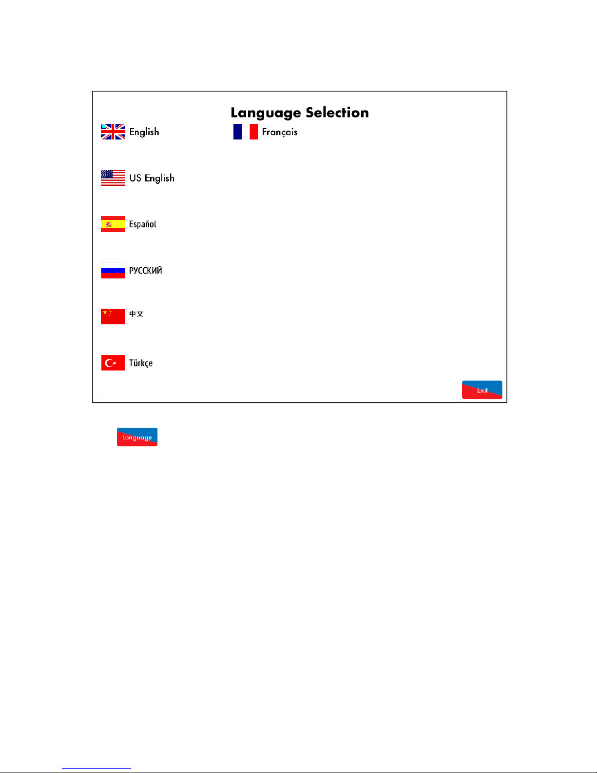
Figure 3.19.1.i Language Selection
Press in the System Configuration screen in Figure 3.19.i to access Language Selection
screen; you be will be prompted to enter the Online Changes password. Please contact your local
approved Autoflame tech centre for this password.
Note: The SD card must contain the language file to be able to select the language. If a language
required is not available, please contact the Autoflame office.
Page 31 Mk8 MM End User Guide 22.05.2017
3.9.1 Language Selection
3 End User Operation
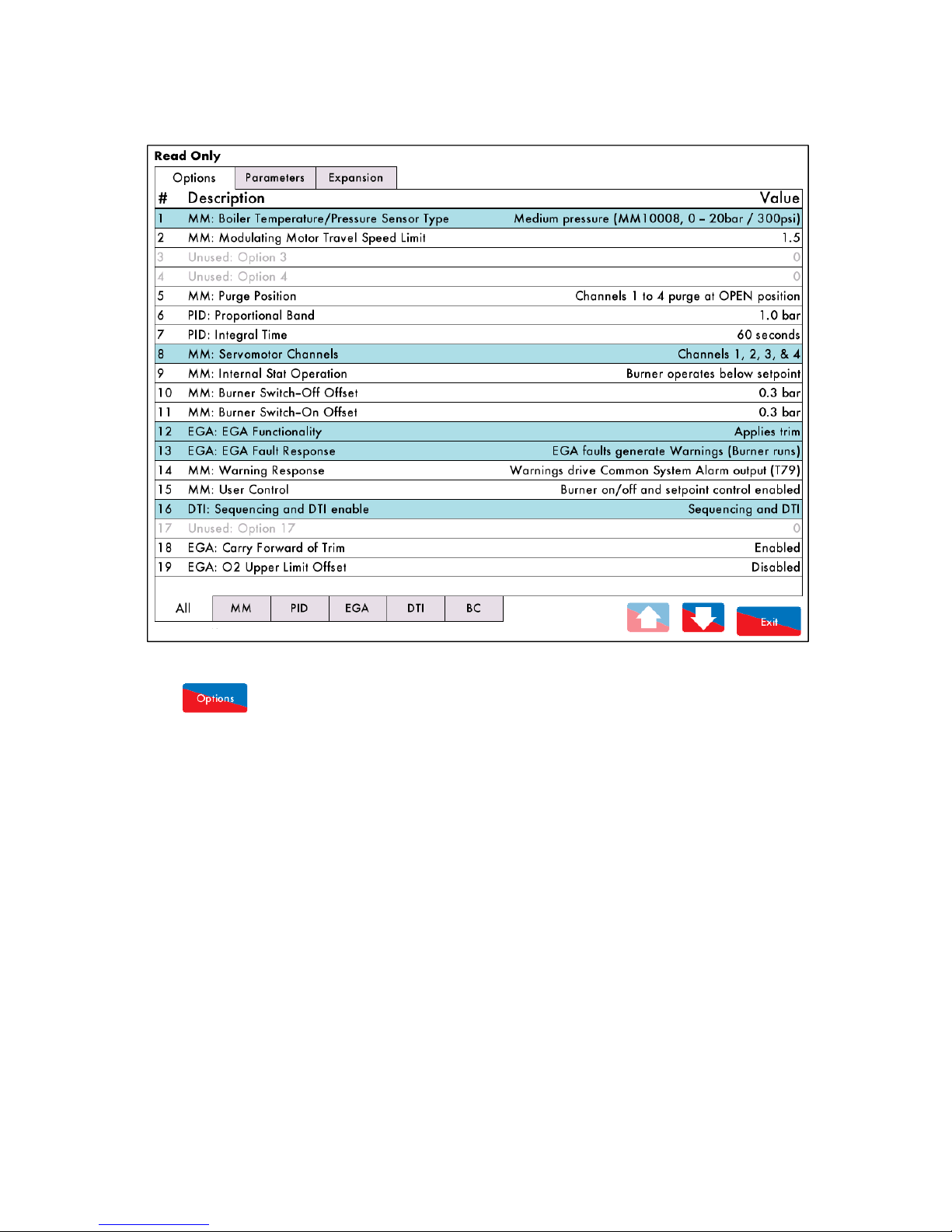
Figure 3.19.2.i Options
Press in the System Configuration screen in Figure 3.19.i to view the Options screen, which
displays all of the options and their ranges and settings. This is a read only mode, so no changes can
be made to the options in this screen. Options highlighted in blue are ones which have been changed
from the default values.
Press on the MM, PID, EGA, DTI and BC tabs to group together options in those categories.
22.05.2017 Mk8 MM End User Guide Page 32
3.9.2 Options
3 End User Operation
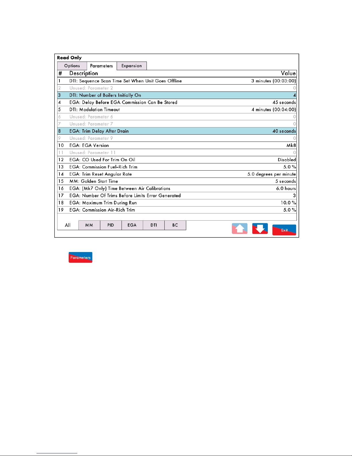
Figure 3.19.3.i Parameters
Press in the System Configuration screen in Figure 3.19.i to view the Parameters screen,
which displays all of the parameters and their ranges and settings. This is a read only mode, so no
changes can be made to the parameters in this screen. Parameters highlighted in blue are ones which
have been changed from the default values.
Press on the MM, PID, EGA, DTI and BC tabs to group together parameters in those categories.
Page 33 Mk8 MM End User Guide 22.05.2017
3.9.3 Parameters

3 End User Operation
Figure 3.19.4.i Expansion Options
Press in the System Configuration screen in Figure 3.19.i to view the Expansion Options
screen, which displays all of the expansion options and their ranges and settings. This is a read only
mode, so no changes can be made to the expansion options in this screen. Expansion options
highlighted in blue are ones which have been changed from the default values.
Press on the MM, PID, EGA, DTI and BC tabs to group together expansion options in those categories.
22.05.2017 Mk8 MM End User Guide Page 34
3.9.4 Expansion Options

3 End User Operation
Figure 3.19.7.i Set Clock
Press in the System Configuration screen in Figure 3.19.i to access the Set Clock screen; you
will be prompted to enter the password (10, 10). Change the time and data using the
arrows and then press and then press .
Note: If the MM is connected to a DTI, then then time and data will be set by the DTI and cannot be
adjusted on the MM.
Page 35 Mk8 MM End User Guide 22.05.2017
3.9.5 Set Clock

3 End User Operation
Figure 3.19.10.i Manual
Press in the System Configuration screen in Figure 3.19.i to view the Manual screen. Press
on the section headings to navigate through the operating manual.
Note: The SD card must contact the manual file to be able to view the operating manual on the MM
screen.
22.05.2017 Mk8 MM End User Guide Page 36
3.9.6 Manual

3 End User Operation
Figure 3.19.11.i Commission Data
Press in the System Configuration screen in Figure 3.19.i to view the Commission Data
screen.
Page 37 Mk8 MM End User Guide 22.05.2017
3.9.7 Commission Data

3 End User Operation
Figure 3.19.12.i Diagnostics
Press in the System Configuration screen in Figure 3.19.i to view the real-time diagnostics.
This data is logged hourly on the SD card for up to 3 months. The minimum and maximum values are
the lowest and highest values the MM as detected for this measurement.
22.05.2017 Mk8 MM End User Guide Page 38
3.9.8 Diagnostics

3 End User Operation
Log
Press in the System Configuration screen in Figure 3.19.i to view the System Log screen,
which stores 1000 entries of the following information:
Stat on/ off
Setting changes
Commission/single point change
Fuel flow commission
MM restart
Setpoint changes
Page 39 Mk8 MM End User Guide 22.05.2017
3.9.9 System
Figure 3.19.13.i System Log

AND LOCKOUTS
Errors occur when the MM detects an internal fault, component out of range, internal check failure or
power supply issue. To clear an error, the MM must be restarted.
Error Message Description
1 Channel 1 Positioning Error Servomotor is outside of the commissioned range
Check wiring on terminals 40 – 47
Check signal cable from the MM to the servomotor is screened at one end
Check potentiometer is zeroed correctly
Go into Commissioning mode, check the servomotor position and ensure that closed is at 0.0
O
2 Channel 2 Positioning Error Servomotor is outside of the commissioned range
Check wiring on terminals 40 – 47
Check signal cable from the MM to the servomotor is screened at one end
Check potentiometer is zeroed correctly
Go into Commissioning mode, check the servomotor position and ensure that closed is at 0.0
O
3 Channel 3 Positioning Error Servomotor is outside of the commissioned range
Check wiring on terminals 40 – 47
Check signal cable from the MM to the servomotor is screened at one end
Check potentiometer is zeroed correctly
Go into Commissioning mode, check the servomotor position and ensure that closed is at 0.0
O
4 Channel 4 Positioning Error Servomotor is outside of the commissioned range
Check wiring on terminals 40 – 47
Check signal cable from the MM to the servomotor is screened at one end
Check potentiometer is zeroed correctly
Go into Commissioning mode, check the servomotor position and ensure that closed is at 0.0
O
5 Channel 7 Positioning Error Servomotor is outside of the commissioned range
Check wiring on terminals DP-, DP+, DPW
Check signal cable from the MM to the servomotor is screened at one end
Check potentiometer is zeroed correctly
Go into Commissioning mode, check the servomotor position and ensure that closed is at 0.0
O
6 Channel 1 Gain Error Servomotor position measurement hardware error
Check wiring and voltages on terminals 40 – 47 and 70 – 77
7 Channel 2 Gain Error Servomotor position measurement hardware error
Check wiring and voltages on terminals 40 – 47 and 70 – 77
8 Channel 3 Gain Error Servomotor position measurement hardware error
Check wiring and voltages on terminals 40 – 47 and 70 – 77
9 Channel 4 Gain Error Servomotor position measurement hardware error
Check wiring and voltages on terminals 40 – 47 and 70 – 77
10 Channel 7 Gain Error Servomotor position measurement hardware error
Check wiring and voltages on terminals DP-, DP+, DPW and DCI, DCD
11 Channel 1 Movement Error Servomotor moves when not expected and vice versa
Check wiring and voltages on terminals 70 – 77
Check servomotors drive in correct direction and valve is not stuck
22.05.2017 Mk8 MM End User Guide Page 40
4 Errors and Lockouts
4 ERRORS
4.1 Errors

Error Message Description
12 Channel 2 Movement Error Servomotor moves when not expected and vice versa
Check wiring and voltages on terminals and 70 – 77
Check servomotors drive in correct direction and damper is not stuck
13 Channel 3 Movement Error Servomotor moves when not expected and vice versa
Check wiring and voltages on terminals and 70 – 77
Check servomotors drive in correct direction and valve is not stack
14 Channel 4 Movement Error Servomotor moves when not expected and vice versa
Check wiring and voltages on terminals and 70 – 77
Check servomotors drive in correct direction and valve is not stuck
15 Channel 7 Movement Error Servomotor moves when not expected and vice versa
Check wiring and voltages on terminals DCI and DCD
Check servomotor drives in correct direction and damper is not stuck
16 Analogue Power Supply Error ADC measured 12V supply out of range
Check wiring for shorts on terminals 41, 47 and 39
17 Digital Power Supply Error ADC measured 3.3V supply out of range
Check for noise on the mains input, wiring and voltages on all terminals
18 EEPROM Error Fault communicating with the on board EEPROM
Contact Autoflame approved local tech centre
19 ADC Error Internal fault
Contact Autoflame approved local tech centre
20 Watchdog Timeout Internal fault
Contact Autoflame approved local tech centre
21 Processor Clock Error Internal fault
Contact Autoflame approved local tech centre
22 System Error Internal fault
Contact Autoflame approved local tech centre
23 Flash Data Error Internal fault
Re-install software SD card
24 Processor Temperature Error Internal fault
Check ambient temperature of unit does not exceed maximum recommended temperature
25 Burner Control Comms Error Internal fault
Contact Autoflame approved local Tech Centre
26 Burner Control Reset Internal fault
Contact Autoflame approved local Tech Centre
27 Software Error Internal fault
Contact Autoflame approved local Tech Centre
28 Zero-Crossing Detection Error Internal fault
Check mains supply going to unit is within acceptable voltage range
29 Mains Input Detection Error Mains input stuck on
Check wiring and voltages on terminals 89 – 92
30 Channel 5 VSD Error Feedback incorrect
Check VSD feedback against commissioned VSD and ensure the feedback is stable
31 Channel 6 VSD Error Feedback incorrect
Check VSD feedback against commissioned VSD and ensure the feedback is stable
Page 41 Mk8 MM End User Guide 22.05.2017
4 Errors and Lockouts

Error Message Description
32 VSD Feedback Change Too
Small
Feedback change detected during commissioning is too
small
Check VSD feedback during commissioning
Check option 99 for VSD on channel 5 and option 109 for VSD on channel 6
Check wiring on terminals 1 – 3, 4 – 6, 10 – 12 and 13 – 15
33 Missing Commissioning Data Internal fault
Check there is commissioning data for all options servomotors/VSD
34 FAR Execution Speed Internal fault
Contact Autoflame approved local Tech Centre
35 Software Error Internal fault
Contact Autoflame approved local Tech Centre
36 Software Error Internal fault
Contact Autoflame approved local Tech Centre
37 Software Error Internal fault
Contact Autoflame approved local Tech Centre
38 Software Error Internal fault
Contact Autoflame approved local Tech Centre
39 VSD Sampling Error VSD feedback current/ voltage too high on channel 5/6
Check wiring on terminals 1 – 3, 4 – 6, 10 – 12 and 13 – 15
40 VSD Feedback Too Low VSD feedback value is too low during commissioning on
channel 5/6
Check VSD feedback while commissioning
41 APS Commission Data Fault No air pressure trim data for a point with EGA trim
Check EGA trim and air pressure trim in fuel-air curve
42 Comm VPS Gas Pressure Low Commissioned gas pressure during VPS below option/
parameter 133 threshold
Check option/ parameter 133 and check gas pressure
Re-commission gas pressure sensor
43 Comm Running Gas Pressure
Low
Commissioned gas pressure during running below option/
parameter 136
Check option/ parameter 136 and check gas pressure
Re-commission gas pressure sensor
44 Comm Air Pressure Low Commissioned air pressure during running below option/
parameter s 147 and 149
Check option/parameters 147 and 149
Re-commission air pressure sensor
45 Software Error Internal fault
Contact Autoflame approved local tech centre
46 Software Error Internal fault
Contact Autoflame approved local tech centre
47 Expansion PF Output (Check F5) Internal fault
Check wiring on terminal PF
Check fuse 5 (2A) on expansion board
48 WL Alarm Output Internal Fault Internal fault
Check expansion option 5
Check wiring and voltages on terminals HAI, 1AI, 2AI
22.05.2017 Mk8 MM End User Guide Page 42
4 Errors and Lockouts

Error Message Description
49 Expansion Servo Hardware Fault Internal fault
Contact Autoflame approved local tech centre
50 Triac Power Supply Error (Check
F2)
Internal fault
Check wiring on terminal 69
Check fuse 2 (2A T)
51 Fused 12V Supply Error (Check
F4)
Internal fault
Check gas/air pressure sensor wiring on terminals 31 – 34, and load detector on 37 – 39
Check fuse 4 (500mA)
52 Fused 13.5V Supply Error
(Check F3)
Internal fault
Check IR scanner wiring on terminals 29, 30, 48, 49 and oil pressure sensor on 48, 49
Check fuse 3 (500mA)
53 Air Pressure Zeroing Fault Commissioned air zero pressure is more than 5mbar from
sensor’s zero value
Check air pressure sensor value during VPS
54 Software error Internal fault
Contact Autoflame approved local Tech Centre
55 Software error Internal fault
Contact Autoflame approved local Tech Centre
56 Software error Internal fault
Contact Autoflame approved local Tech Centre
57 Software error Internal fault
Contact Autoflame approved local Tech Centre
58 Software error Internal fault
Contact Autoflame approved local Tech Centre
59 Software error Internal fault
Contact Autoflame approved local Tech Centre
60 Software error Internal fault
Contact Autoflame approved local Tech Centre
61 Software error Internal fault
Contact Autoflame approved local Tech Centre
62 Software error Internal fault
Contact Autoflame approved local Tech Centre
63 Software error Internal fault
Contact Autoflame approved local Tech Centre
64 ADC Reference Voltage Error Hardware fault
Contac Contact Autoflame approved local Tech Centre
Contact Autoflame approved local Tech Centre
65 Software error Internal fault
Contact Autoflame approved local Tech Centre
66 Software error Internal fault
Contact Autoflame approved local Tech Centre
67 Software error Internal fault
Contact Autoflame approved local Tech Centre
Page 43 Mk8 MM End User Guide 22.05.2017
4 Errors and Lockouts
Lockouts occur when the MM detects a fault with the burner operation such as VPS, gas/air pressure
sensor and flame scanners. The lockout must be cleared and investigated on the MM.
Lockout Message Description
1 CPI Input Wrong State Proof of closure switch opened during ignition sequence
Check wiring on terminal 55
Check proof of closure switches
2 No Air Proving No air pressure during start/ firing
Check wiring on terminal 54
Check air pressure switch
Check air pressure sensor
Check air pressures during running
3 Ignition Output Fault Voltage detected when output is off (and vice versa)
Check wiring and voltage on terminal 63
4 Motor Output Fault Voltage detected when output is off (and vice versa)
Check wiring and voltage on terminal 58
5 Start Gas Output Fault Voltage detected when output is off (and vice versa)
Check wiring and voltage on terminal 59
6 Main Gas 1 Output Fault Voltage detected when output is off (and vice versa)
Check wiring and voltage on terminal 60
7 Main Gas 2 Output Fault Voltage detected when output is off (and vice versa)
Check wiring and voltage on terminal 61
8 Vent Valve Output Fault Voltage detected when output is off (and vice versa)
Check wiring and voltage on terminal 62
9 Failsafe Relay (Check F1) Voltage detected when output is off (and vice versa)
Check wiring and voltage on terminal 57
Check fuse 1 (6.3A T) and wiring on terminals 50 – 64
10 Simulated Flame Flame is present when it not should be
Isolate gas/ oil immediately
Call a certified Commissioning Engineer to investigate
If this lockout occurs during shutdown a post-purge may be required for after burn
11 VPS Air Proving Fail Leak detected during ‘air proving’ part of VPS
Check 1
st
main valve
Call a certified Commissioning Engineer to investigate
12 VPS Gas Proving Fail Leak detected during ‘gas proving’ part of VPS
Check option/parameter 133
Check 2
nd
main gas valve and vent valve
Check pilot valve if using single valve pilot
Isolate gas and call a certified Commissioning Engineer to investigate
13 No Flame Signal No flame detected during ignition/ firing
Visually check flame
Check the flame scanner
Call a certified Commissioning Engineer to investigate
14 Shutter Fault UV signal detected during shutter operation on self-check
Check wiring on terminals 21 and 22
Check UV scanner type and check option/ parameter 110 is set accordingly
22.05.2017 Mk8 MM End User Guide Page 44
4 Errors and Lockouts
4.2 Lockouts

Lockout Message Description
15 NO CPI Reset Proof of closure switch not made after valves closed
Check wiring on terminal 55 and check proof of closure switches
16 Prolonged Lockout Reset Prolonged voltage detected on terminal 56/ lockout reset
button permanently pressed
Check lockout reset button is not pressed
Check wiring on terminal 56
17 Gas Pressure Low Gas pressure low limit exceeded while firing(gas sensor)
Check gas pressure
Check option/ parameter 136
18 Gas Pressure High Gas pressure high limit exceeded while firing (gas sensor)
Check gas pressure
Check option/ parameter 137
19 RAM Test Failed Hardware fault
Contact Autoflame approved local tech centre
20 PROM Test Failed Hardware fault
Contact Autoflame approved local tech centre
21 FSR Test 1A Internal relay test failed
Check wiring and voltages on terminals 50 – 63
22 FSR Test 2A Internal relay test failed
Check wiring and voltages on terminals 50 – 63
23 FSR Test 1B Internal relay test failed
Check wiring and voltages on terminals 50 – 63
24 FSR Test 2B Internal relay test failed
Check wiring and voltages on terminals 50 – 63
25 Watchdog Fail 2A Internal check failed
Contact Autoflame approved local tech centre
26 Watchdog Fail 2B Internal check failed
Contact Autoflame approved local tech centre
27 Watchdog Fail 2C Internal check failed
Contact Autoflame approved local tech centre
28 Watchdog Fail 2D Internal check failed
Contact Autoflame
29 Input Fault Power supply fault
Check mains voltage to the MM
32 Gas Pressure Low Limit Gas pressure lower than commissioned VPS value
Check gas pressure sensor value
Check option/parameter 136
33 VPS Air Zeroing Gas pressure sensor cannot be zeroed at VPS venting
Check gas pressure is within zero range (see MM Application Possibilities)
Check vent valve
36 Oil Pressure Too Low Oil pressure below offset lower limit during running
Check option/parameter 139
Check oil pressure sensor
37 Oil Pressure Too High Oil pressure above offset upper limit during running
Check option/parameter 140
Check oil pressure sensor
Page 45 Mk8 MM End User Guide 22.05.2017
4 Errors and Lockouts

Lockout Message Description
39 Freeze Timeout MM kept in Phase Hold for more than 10minutes
MM kept in Phase Hold during commissioning for more than 10 minutes
40 Purge Air Pressure Low Insufficient air pressure during purge
Check option/parameter 141
Check air pressure sensor/ air pressure switch
42 Terminal 86 Inverse Input detected on both terminals 85,86 where there
should not be, and vice versa
Check option/parameter 122
Check wiring and voltages on terminals 85, 86
43 Terminal 85/86 Fault Hardware fault on terminals 85/86
Check wiring and voltages on terminals 85, 86 and contact Autoflame
44 Proving Circuit Fail T52 Loss of input on terminal 52; MM must see input at all
times from position to purge to post purge
Check wiring on terminal 52
45 No Proving Circuit Set Secondary proving timeout elapsed
Check option/parameter 157
Check wiring on terminal 52
46 Proving Interlock Timeout Purge interlock timeout elapsed
Check option/ parameters 155 and 158
Check wiring on terminal 81
52 High IR Ambient Flame detected when there should not be
Visually check flame and check IR scanner
Call a certified Commissioning Engineer to investigate
53 IR Comms Lost Loss of comms with IR scanner
Check wiring and screen on terminals 29, 30, 48 and 49
Check that the IR scanner is not removed from the magnetic ring socket
54 Watchdog Long X A Internal check failed
Contact Autoflame approved local tech centre
55 Watchdog Long Y A Internal check failed
Contact Autoflame approved local tech centre
56 Watchdog Off A Internal check failed
Contact Autoflame approved local tech centre
57 Watchdog Short X B Internal check failed
Contact Autoflame approved local tech centre
58 Watchdog Short Y B Internal check failed
Contact Autoflame approved local tech centre
59 Watchdog Long X B Internal check failed
Contact Autoflame approved local tech centre
60 Watchdog Long Y B Internal check failed
Contact Autoflame approved local tech centre
61 Watchdog Off B Internal check failed
Contact Autoflame approved local tech centre
62 UV Signal Too High Internal check failed for UV
Check wiring on terminals 21, 22, 50 and 51
22.05.2017 Mk8 MM End User Guide Page 46
4 Errors and Lockouts

Lockout Message Description
63 Purge Limit Switch Interlock not made on terminal 81
Check option/ parameter 155
Check wiring on terminal 81
64 Start Limit Switch Interlock not made on terminal 80
Check option/ parameter 154
Check wiring on terminal 80
65 FSR A Internal check failed
Check wiring and voltages on terminals 50 – 63
66 FSR B Internal check failed
Check wiring and voltages on terminals 50 – 63
67 Gas Sensor Comms Signal lost from gas pressure sensor
Check wiring and screen on terminals 31 – 34
68 Gas Sensor Type Internal fault
Contact Autoflame approved local tech centre
69 Gas Sensor Fault Internal pressure sensor fault
Contact Autoflame approved local tech centre
70 UV Pot Fault Internal UV scanner fault
Contact Autoflame approved local tech centre
71 Air Sensor Comms Signal lost from air pressure sensor
Check wiring and screen on terminals 31 – 34
72 Air Sensor Type Internal fault
Contact Autoflame approved local tech centre
73 Air Sensor Fault Internal pressure sensor fault
Contact Autoflame approved local tech centre
74 Air Sensor Zero Air pressure is more than 5mbar from sensor’s zero value
Check air pressure sensor value during VPS
75 Air Sensor Signal High Air pressure is above 400mbar
Check Autoflame approved local tech centre
76 Air Sensor Error Window Air pressure outside of these limits for 3 seconds
Check air pressure
Check option/parameter 147
77 Wait Air Switch Timeout Voltage has not been reset for 2minutes
Check air pressure sensor value during VPS
Check voltage has been reset on terminal 54 within 2minutes before run to purge
Check wiring and voltage on terminal 54
78 Gas Proving Fail High Gas pressure too high during VPS
Isolate gas
Check 1
st
main valve and vent valve
Check option/ parameters 133 and 134
Call a certified Commissioning Engineer to investigate
79 FSR Test 1C Hardware fault
Contact Autoflame approved local tech centre
80 Timeout on Reaching Purge Time set in option/parameter 124 has elapsed
Check option/parameter 124
81 Oil Pressure Sensor Fault No comms received from oil pressure sensor
Check wiring and screen on terminals 48, 49
Page 47 Mk8 MM End User Guide 22.05.2017
4 Errors and Lockouts
Lockout Message Description
82 Purge Pressure Proving Input Input on T81 read high during relay test phases
Input has been made before the blower starts; it should only be made continuously during purge.
Check wiring on terminal 81.
198 BC Input Short Internal fault
Contact Autoflame approved local tech centre
199 Lockout 199 Internal fault
Contact Autoflame approved local tech centre
200 Lockout Cleared Lockout has been cleared
MM status after lockout has been reset (Modbus)
201 Power up CPU Test Fail Internal check failed
Contact Autoflame approved local tech centre
202 Power up EEPROM Test Fail Internal check failed
Contact Autoflame approved local tech centre
22.05.2017 Mk8 MM End User Guide Page 48
4 Errors and Lockouts
Alarms and warnings are faults detected with the system operation. If an alarm occurs, the burner will
stop running, and if a warning occurs, the burner will continue to run. The following
options/parameters set whether system operation faults are set as alarms or warnings:
Option 13 EGA Fault Response
Option 14 Warning Response
Expansion Option 9 Burner Operation at High Water
Expansion Option 20 Burner Operation on Feed water Control Fault
Expansion Option 88 Action on Pressure Sensor Fault
Fault Message Description
1 EGA Internal Error Fault on EGA
Alarm or warning depending on option 13
Check EGA for fault description
2 No EGA Communications MM has lost communications with EGA
Alarm or warning based on option 13 (warning if option 12 is set to monitoring only)
Check parameter 10 is set to correct EGA version
Check EGA operating mode is selected as ‘EGA with MM’
Check wiring between EGA and MM (terminals 25 and 26 on MM)
3 O2 Upper Limit O2 value is above upper limit offset of commissioned value*
Alarm or warning depending on option 13
Check exhaust gas readings and option 19
4 O2 Absolute Limit O2 value is below absolute limit*
Alarm or warning depending on option 13
Check exhaust gas readings and option 25
5 O2 Lower Limit O2 value is below lower limit offset of commissioned value*
Alarm or warning depending on option 13
Check exhaust gas readings and option 22
6 CO2 Upper Limit CO2 value is above upper limit offset of commissioned value*
Alarm or warning depending on option 13
Check exhaust gas readings and option 20
7 CO2 Absolute Limit CO2 value is above absolute limit*
Alarm or warning depending on option 13
Check exhaust gas readings and option 26
8 CO2 Lower Limit CO2 value is below lower limit offset of commissioned value*
Alarm or warning depending on option 13
Check exhaust gas readings and option 23
9 CO Upper Limit CO value is above upper limit offset of commissioned value*
Alarm or warning depending on option 13
Check exhaust gas readings and option 21
10 CO Absolute Limit CO value is above absolute limit*
Alarm or warning depending on option 13
Check exhaust gas readings and option 27
11 NO Upper Limit NO value is above upper limit offset of commissioned value*
Alarm or warning depending on option 13
Check exhaust gas readings and parameter 94
Page 49 Mk8 MM End User Guide 22.05.2017
4 Errors and Lockouts
4.3 Alarms and Warnings

Fault Message Description
12 Exhaust Temperature Upper
Limit
Exhaust temperature is above upper limit offset of
commissioned value*
Alarm or warning depending on option 13
Check exhaust gas readings and parameter 96
13 Exhaust Temperature
Absolute Limit
Exhaust temperature is above absolute limit*
Alarm or warning depending on option 13
Check exhaust gas readings and parameter 97
50 Load Sensor Fault Incorrect/no load sensor detected
Alarm
Check option 1
Check wiring on terminals 37 – 39
51 Auxiliary Input Low 3mA or lower received from 4-20mA external modulation/
external setpoint
Alarm
Check parameter 69
Check feedback from external modulation/ external setpoint controller
Check wiring on terminals 7 – 9
80 Oil Pressure Sensor Fault No comms received from oil pressure sensor
Warning (lockout 81 if oil pressure limits set in option/parameters 139 and 140)
Check wiring and screen on terminals 48, 49
100 Cap Probe 1 Communications
Fault
No comms with capacitance probe 1
Alarm
Check wiring and screen on terminals 1P+, 1P-, 1T+ and 1T-
101 Cap Probe 2 Communications
Fault
No comms with capacitance probe 2
Alarm
Check wiring and screen on terminals 2P+, 2P-, 2T+ and 2T-
102 Cap Probe 1 Short Circuit Hz reading is below 10kHz
Alarm
Check water level Hz reading
Check wiring on terminals 1P+, 1P-, 1T+ and 1T-
103 Cap Probe 2 Short Circuit Hz reading is below 10kHz
Alarm
Check water level Hz reading
Check wiring on terminals 2P+, 2P-, 2T+ and 2T-
104 Cap Probe 1 Temp
Compensation Error
Temperature corrected probe reference is not as expected
Alarm
Re-commission capacitance probes at temperature
105 Cap Probe 2 Temp
Compensation Error
Temperature corrected probe reference is not as expected
Alarm
Re-commission capacitance probes at temperature
106 Cap Probe 1 Still Water
Detected
Wave signature high to low peak distance is less than still
water threshold
Alarm
Check still water threshold in expansion option 28
Check capacitance probe 1 reading history
22.05.2017 Mk8 MM End User Guide Page 50
4 Errors and Lockouts
Fault Message Description
107 Cap Probe 2 Still Water
Detected
Wave signature high to low peak distance is less than still
water threshold
Alarm
Check still water threshold in expansion option 28
Check capacitance probe 2 reading history
108 Cap Probe 1 Serial Number
Mismatch
Probe serial number detected is not the commissioned probe
serial number
Alarm
If changing capacitance probe 1, re-commission is required
109 Cap Probe 2 Serial Number
Mismatch
Probe serial number detected is not the commissioned probe
serial number
Alarm
If changing capacitance probe 2, re-commission is required
110 Cap Probe 1 Detected But
Not Optioned
Probe connected but not optioned
Alarm
Check expansion options 1 and 3
Check wiring on terminals 1P+, 1P-, 1T+ and 1T-
111 Cap Probe 2 Detected But
Not Optioned
Probe connected but not optioned
Alarm
Check expansion options 1 and 3
Check wiring on terminals 2P+, 2P-, 2T+ and 2T-
112 External Level Sensor Input
Low
3mA or lower received from 4-20mA external level sensor
Alarm
Check feedback from external level sensor
Check wiring on terminals EX- and EX+
113 Probe Reading Mismatch Difference between probes/sensor readings is below
mismatch threshold
Alarm
Check expansion option 27
Check capacitance probes and sensor readings
114 Probe Serial Numbers are the
Same
One capacitance probe detected on both capacitance probe
terminals
Alarm
If using two capacitance probes, then two individual probes must be connected
Check wiring on terminals 1P+, 1P-, 1T+, 1T-, 2P+, 2P-, 2T+ and 2T-
120 Aux WL Inputs Mismatch High water and 1st or 2nd low auxiliary level inputs detected
simultaneously
Alarm
Check wiring on terminals HAI, 1AI and 2AI
121 Water Levels Diverse Probes/ sensor detects 1st or 2nd low and high water
simultaneously
Alarm
Check water level readings for probes and sensor if optioned
Re-commission probes/sensor
122 Permanent Alarm Reset Input Input held on alarm reset terminal for more than 10 seconds
Alarm
Check input on terminal M/R
Page 51 Mk8 MM End User Guide 22.05.2017
4 Errors and Lockouts
Fault Message Description Type
123 Second Low Probe
Communications Fault
No comms with second low probe
Alarm
Check wiring and screen on terminals 5T+, 5T-, 4P- and 4P+
124 Second Low Probe Hardware
Fault
Internal check failed
Alarm
Contact Autoflame approved local tech centre
125 Permanent Test Input Input held on test terminal for more than 60 seconds
Alarm
Check input on terminal TST
126 Second Low Probe Detected
But Not Optioned
Second low probe connected but not optioned
Alarm
Check expansion option 6
Check wiring on terminals 5T+, 5T-, 4P- and 4P+
127 Aux WL Inputs Detect But Not
Optioned
Mains detected on auxiliary WL inputs but not optioned
Alarm
Check expansion option 5
Check wiring on terminals HAI, 1AI and 2AI
130 Feed Water Servo Position
Error
Servomotor is outside of the commissioned range
Alarm or warning or depending on expansion option 20
Check wiring on terminals P-, FW and P+
Check signal cable form the MM to the servomotor is screened at one end
Check that the servomotor is zeroed correctly
131 Feed Water Servo Movement
Error
Servomotor moves when not expected and vice versa
Alarm or warning depending on expansion option 20
Check wiring and voltages on terminals MVI and MVD
Check servomotor drives in correct direction
Check feed water valve is not stuck
150 High Water Probes/sensor detect water level above commissioned high
water
Alarm or warning depending on expansion option 9
Check water level reading
151 Pre-High Water Probes/sensor detect water level above set pre-high water
Warning
Check water level reading
Check expansion option 7
152 Pre-1st Low Probes/sensor detect water level below set pre-1st low
Warning
Check water level reading
Check expansion option 8
153 1st Low Probes/sensor detect water level below commissioned 1st low
Alarm
Check water level reading
1
st
low alarm will automatically clear if water level increases above 1st low
22.05.2017 Mk8 MM End User Guide Page 52
4 Errors and Lockouts

Fault Message Description
154 2nd Low Probes/sensor detect water level below 2nd low
Alarm
Check water level reading
2
nd
low alarm requires manual reset
155 Shunt Switch Time Expired Once shunt switch time expires, system goes to normally
running
Warning
If water drops after shunt switch time expires, system will generate 1
st
or 2nd low as relevant
200 Top Blowdown Sensor
Communications Fault
No comms with the top blowdown sensor
Warning
Check wiring and screen on terminals 3P+, 3P-, 3T+ and 3T-
201 Top Blowdown Servo Position
Error
Servomotor is outside of the commissioned range
Warning
Check wiring on terminals P-, TW, P+ and TBI, TBD
Check signal cable form the MM to the servomotor is screened at one end
Check that the servomotor is zeroed correctly
202 Top Blowdown Servo
Movement Error
Servomotor moves when not expected and vice versa
Warning
Check wiring on terminals TBI and TBD
Check servomotor drives in correct direction
Check top blowdown valve is not stuck
250 Top Blowdown Reading High TDS value detected too high
Warning
Check expansion option 46 and TDS value
300 Bottom Blowdown Controller
Comms
No comms with bottom blowdown controller
Warning
Check bottom blowdown controller is powered on and enabled
Check wiring and screen on terminals 5T+ and 5T-
301 Bottom Blowdown Controller
Software Fault
Internal check failed
Warning
Contact Autoflame approved local tech centre
302 Bottom Blowdown Servo
Closing Fault
No movement detected when bottom blowdown valve goes
to close
Warning
Check wiring on terminals 5T+ and 5T-
Check bottom blowdown valve is not stuck
303 Bottom Blowdown Servo
Opening Fault
No movement detected when bottom blowdown valve goes
to open
Warning
Check wiring on terminals 5T+ and 5T-
Check bottom blowdown valve is not stuck
304 Bottom Blowdown Servo
Battery Drive Fault
Battery has failed on bottom blowdown
controller
Warning
Warning
Contact Autoflame approved local tech centre
Page 53 Mk8 MM End User Guide 22.05.2017
4 Errors and Lockouts

Fault Message Description
305 Bottom Blowdown Controller
Main Power Fault
Main power has failed on bottom blowdown controller
Warning
Contact Autoflame approved local tech centre
350 Bottom Blowdown Servo Not
Commissioned
Bottom blowdown controller has not been requested to drive
servomotor to closed since it was powered on
Warning
Commission bottom blowdown servomotor
400 Draught Pressure Sensor
Timeout
No comms within 2 seconds from draught pressure sensor
Alarm or warning depending on option 88
Check wiring and screen on terminals DT+, DT-, DP- and DP+
410 Draught Pressure Outside
Tolerance
Pressure is outside of set tolerance
Alarm or warning depending on option 88
Check expansion option 87
420 Fuel flow Feedback Input Low 3mA or lower received from 4-20mA external fuel flow input
Warning
Check feedback from external fuel flow input
Check wiring on terminals EX- and EX+
430 Fuel flow Feedback Below
Tolerance
Fuel flow signal below fuel flow feedback fault tolerance
Warning
Check feedback from external fuel flow input
Check option 60
431 Fuel flow Feedback Above
Tolerance
Fuel flow signal above fuel flow feedback fault tolerance
Warning
Check feedback from external fuel flow input
Check option 60
440 Temperature Sensor T1Fault Fault or no comms with T1 sensor
Warning
Check wiring and screen on terminals –and T1
441 Temperature Sensor T2 Fault Fault or no comms with T2 sensor
Warning
Check wiring and screen on terminals – and T2
442 Temperature Sensor T3 Fault Fault or no comms with T3 sensor
Warning
Check wiring and screen on terminals – and T3
443 Make Up Flow Meter Fault Fault or no comms with make up flow meter
Warning
Check wiring and screen on terminals F- and MF
444 Condensate Flow Meter Fault Fault or no comms with condensate flow meter
Warning
Check wiring and screen on terminals F- and CF
445 Deaerator IO Comms Fault Fault or no comms with deaerator IO
Warning
Check wiring and screen on terminals 6T+ and 6T-
22.05.2017 Mk8 MM End User Guide Page 54
4 Errors and Lockouts

Fault Message Description
500 Multi-Burner Communications
Fault
Loss of comms between MMs in multi-burner loop
Alarm
Check wiring on terminals 23 and 24 on all MMs in multi-burner loop
501 Multi-Burner Version
Mismatch
Software versions of MMs in multi-burner loop do not match
Alarm
Check that software versions of MMs in multi-burner loop match
502 Multi-Burner Not Polled MM in multi-burner loop has been detected but not polled
Alarm
Check option 51 on master MM
Check wiring on terminals 23 and 24
503 Multi-Burner Config (Multi-
Burner Mode)
Multi-burner mode is not the same for all MMs in loop
Alarm
Check option 43 on all MMs in multi-burner loop
504 Multi-Burner Config (Fuel
Index)
Same fuel number must be selected on all MMs in multiburner loop
Alarm
Check which fuel is selected on all MMs in multi-burner loop
Check wiring on terminals 89, 90, 91 and 92
505 Multi-Burner Config (Fuel
Type)
Fuel type is not the same for all MMs in multi-burner loop
Alarm
Check option/parameters 150 – 153 on all MMs in multi-burner loop
506 Multi-Burner Config (Pilot
Type)
Pilot type not the same for all MMs multi-burner loop
Alarm
Check option/parameter 111 on all MMs in multi-burner loop
507 Multi-Burner Config (Load
Sensor)
Load sensor not set the same for all MMs in multi-burner loop
Alarm
Check option 1 on all MMs in multi-burner loop
550 Fuel Flow Meter Fault Less than 3mA signal received from fuel flow meter
Alarm or warning depending on expansion option 152 (if set to warning, the MM will use the
commissioned value without any fuel or air servomotor adjustment)
Check wiring and screen on terminal MF and F-
551 Air Flow Meter Fault Less than 3mA signal received from air flow meter
Alarm or warning depending on expansion option 152 (if set to warning, the MM will use the
commissioned value without any fuel or air servomotor adjustment)
Check wiring and screen on terminal EX+ and EX-
552 Fuel Temperature Sensor
Fault (T2)
Fault or no comms with T2 sensor
Warning (MM will use commissioned temperature)
Check wiring and screen on terminals – and T2
553 Air Temp Sensor Fault (T3) Fault or no comms with T3 sensor
Warning (MM will use commissioned temperature)
Check wiring and screen on terminals – and T3
Page 55 Mk8 MM End User Guide 22.05.2017
4 Errors and Lockouts

Fault Message Description
554 Fuel Pressure Sensor Fault Fault or no comms with fuel pressure sensor
Warning or lockout if VPS and/or pressure limits enabled in option/parameters 125 – 128 (if
warning, MM uses commissioned pressure)
Check wiring and screen on terminals 31 – 34
555 Air Pressure Sensor Fault Fault or no comms with air pressure
sensor
Warning/Lockout
– option 148
Check wiring and screen on terminals 31 – 34
Lockout if option 148 is set for air pressure sensor in flame safeguard
560 Fully Metered Air Adjustment
Failure
Air adjustment has reached limit and
fuel-air ratio still not met
Alarm/Warning –
exp option 151
Check for changes affecting combustion including fuel/air pressure, temperature etc.
Warning if expansion option 151 is set to 1
Warning and air adjustment is disabled if expansion option 151 is set to 2
580 Servo Control I/O Unit
Communications Fault
Fault or no comms with the servo
control IO module
Alarm
Check for wiring on terminals 6T+ and 6T-
581 Servo Control I/O Unit
Channel 1 Output Fault
4-20mA output detects open circuit Alarm
Check wiring on output 1 on I/O module
582 Servo Control I/O Unit
Channel 2 Output Fault
4-20mA output detects open circuit Alarm
Check wiring on output 2 on I/O module
583 Servo Control I/O Unit
Channel 3 Output Fault
4-20mA output detects open circuit Alarm
Check wiring on output 3 on I/O module
584 Servo Control I/O Unit
Channel 4 Output Fault
4-20mA output detects open circuit Alarm
Check wiring on output 4 on I/O module
585 Servo Control I/O Unit
Channel 7 Output Fault
4-20mA output detects open circuit Alarm
Check wiring on output 5 on I/O module
586 Servo Control I/O Unit
Channel 1 Input Fault
4-20mA input less than 3mA Alarm
Check wiring on input 1 on I/O module
587 Servo Control I/O Unit
Channel 2 Input Fault
4-20mA input less than 3mA Alarm
Check wiring on input 2 on I/O module
588 Servo Control I/O Unit
Channel 3 Input Fault
4-20mA input less than 3mA Alarm
Check wiring on input 3 on I/O module
589 Servo Control I/O Unit
Channel 4 Input Fault
4-20mA input less than 3mA Alarm
Check wiring on input 4 on I/O module
590 Servo Control I/O Unit
Channel 7 Input Fault
4-20mA input less than 3mA Alarm
Check wiring on input 5 on I/O module
*When option 12 is set to 3 for trim and combustion limits, the combustion limits are evaluated once
per trim cycle. A combustion limit error will occur if the current exhaust value has crossed the
combustion limit for the number of trim cycles set in parameter 17 (the default value is 3 cycles).
22.05.2017 Mk8 MM End User Guide Page 56
4 Errors and Lockouts

Conflicts
Some of the options, parameters and expansion options may require another option, parameter or
expansion option to be set. Please see the below table for these settings conflicts. A setting conflict will
result in the MM being forced in to Commission mode.
Setting Conflict Message
(1) (P53, P54, P55, P56) External load sensor incorrectly configured
The external load sensor must be set with the minimum and maximum values and voltages.
Check option 1 and parameters 53 – 56.
(1) (81, 83) OTC setpoints too high for optioned load sensor
If minimum and maximum setpoints OTC setpoints must be set within the possible range of the
optioned load detector.
Check option 1, 81 and 83.
(9) (45) Internal stat must be disabled if load sensor not present
If external modulation is enabled without a load sensor, the internal stat must always be closed.
Check options 9 and 45.
(30) (31) Invalid remote sepoint configuration
The Minimum Remote Setpoint (DTI/Modbus/External) cannot be set higher than the Maximum
Remote Setpoint (DTI/Modbus/External) and vice versa.
Check options 30 and 31.
(43) (44) (E1) Water level control only be on the multi-burner master
Water level control should only be enabled on the master (multi-burner ID 1 set in option 44),
when using the multi-burner function.
Check options 43 ,44 and expansion option 1.
(43) (44) (16) Sequencing only be only the multi-burner master
Only the master (multi-burner ID 1 set in option 44) can be set for sequencing.
Check options 16, 43 and 44.
(43) (44) (12) EGA and trim can only be on the multi-burner master
Only the master (multi-burner ID 1 set in option 44) can be optioned with an EGA.
Check options 12, 43 and 44.
(43) (44) (E110) Firstouts can only be on the multi-burner master
Only the master (multi-burner ID 1 set in option 44) can have first outs enabled.
Check options 43, 44 and expansion option 110.
(43) (44) (E120) Heat-flow can only be on the multi-burner master
Only the master (multi-burner ID 1 set in option 44) can have heat flow function enabled.
Check options 43, 44 and expansion option 120.
(43) (44) (45) External modulation can only be on the multi-burner master
Only the master (multi-burner ID 1 set in option 4) can be set for external modulation.
Check options 43 – 45.
(43) (44) (E82) Draught control can only be on the multi-burner master.
Only the master (multi-burner ID 1 set in option 4) can be set for draught control.
Check options 43 and 44, and expansion option 82.
(43) (57) Fuel flow metering must be enabled for multi-burner
The multi-burner function requires fuel flow metering.
Check options 43 and 57.
(43) (135) NFPA Post Purge cannot be optioned with multi-burner
The multi-burner function can only use standard, not NFA post purge.
Check option 43 and option/parameter 135.
Page 57 Mk8 MM End User Guide 22.05.2017
4 Errors and Lockouts
4.4 Settings

Setting Conflict Message
(45) (55) External modulation conflict
Switched T88 external modulation is not set with permanent external modulation.
Check options 45 and 55.
(45/55) (16) External modulation conflict
External modulation cannot be used on any MMs in sequencing.
Check options 16, 45 and 55
(45) (P72) External modulation and external setpoint both optioned
External modulation and external setpoint cannot be used simultaneously.
Check option 45 and parameter 72.
(81, 82, 83, 84) OTC Configuration invalid
Setpoints at minimum and maximum outside temperatures cannot be set the same.
Minimum and maximum outside temperatures cannot be set the same.
Check options 81, 82, 83 and 84
(111) (122) Flame scanner changeover cannot be optioned with no pilot.
If no pilot is set, then flame scanner changeover cannot be used.
Check option/parameters 111 and 122.
(111) (130) Single valve pilot cannot be optioned with no pilot.
If no pilot is set, then gas valve configuration cannot be set for single valve pilot.
Check option/parameters 111 and 130.
(112, 135) (158) Purge pressure proving timeout shorter than pre-purge time.
Purge pressure proving timeout must be longer than the pre-purge time
Check option/parameters 112, 135 and 158.
(118, 135) (158) Purge pressure proving timeout shorter than post-purge time.
Purge pressure proving timeout must be longer than the post-purge time
Check option/parameters 118, 135 and 158.
(118) (135) NFPA Post Purge must be at least 15 seconds.
If NFPA Post Purge is enabled, then this time must be set to a minimum of 15 seconds.
Check option/parameters 118 and 135
(125) (150) Valve proving cannot be optioned when fuel type is oil (fuel 1)
Valve proving can only be used for gas
Check option/parameters 125 and 150
(126) (151) Valve proving cannot be optioned when fuel type is oil (fuel 2)
Valve proving can only be used for gas
Check option/parameters 126 and 151
(127) (152) Valve proving cannot be optioned when fuel type is oil (fuel 3)
Valve proving can only be used for gas
Check option/parameters 127 and 152
(128) (153) Valve proving cannot be optioned when fuel type is oil (fuel 4)
Valve proving can only be used for gas
Check option/parameters 128 and 153
(125, 126, 127, 128) (129) (135) Post VPS cannot be optioned with NFPA Post Purge.
If NFPA post purge is enabled for gas, VPS can only be set for operating before burner start-up.
Check option/parameters 125, 126, 127, 128, 129 and 135.
(P85) (16) Modulation exerciser cannot be used with sequencing.
Modulation exerciser should be used for test purposes and cannot be used with sequencing.
Check option 16 and parameter 85.
22.05.2017 Mk8 MM End User Guide Page 58
4 Errors and Lockouts

Setting Conflict Message
(P89) (16) Stat exerciser cannot be used with sequencing.
Stat exerciser should be used for test purposes and cannot be used with sequencing.
Check option 16 and parameter 89.
(P99) (P100) Graceful shutdown and assured low fire shut off not allowed.
If graceful shutdown is set, then assured low fire shut off cannot be used.
Check parameters 99 and 100.
(E1) (1) Water level control requires a boiler pressure sensor.
Water level control cannot be used with a hot water boiler (load/external temperature detector).
Check expansion option 1 and option 1.
(E1) (E3, E4) At least one analogue level sensor required.
If water level is enabled with one capacitance probe, then an external level sensor is required.
Check expansion options 1, 3 and 4.
(E1) (E3, E4, E5, E6) Sensor enabled but water level control disabled.
Water level control enabled must be enabled if capacitance probes, external level sensor, 2
nd
low
probe or auxiliary water level alarm inputs are set.
Check expansion options 1, 3, 4, 5 and 6.
(E3, E4, E5, E6) At least two level sensing elements are required.
A minimum of two of the following level sensing elements is required: capacitance probe, external
level sensor, auxiliary water level alarm input or second low probe.
Check expansion options 3, 4, 5 and 6.
(E4) (57) External level sensor cannot be optioned with fuel flow feedback
External level sensor cannot be used with fuel flow feedback, as they use same terminals.
Check expansion option 4 and option 57.
(E11) (E12) Pump turn off point must be above pump turn on point.
Pump turn off point cannot be set lower than pump turn on point.
Check expansion options 11 and 12.
(E17) (E40) Bypass valve cannot be optioned with solenoid top blowdown.
Bypass and solenoid top blowdown cannot be used together, as they use same terminals.
Check expansion options 17 and 40.
(E28) (E3) External level sensor without scaling requires a capacitance probe.
If external level sensor does not have a scale to indicate what level the 4-20mA signal represents,
a capacitance probe is required.
Check expansion options 3 and 38.
(E40) (1) Top blowdown requires a boiler pressure sensor.
Top blowdown cannot be used with a hot water boiler (load/external temperature detector).
Check expansion option 40 and option 1.
(E42) (E46) TDS warning level less than TDS target.
TDS warning level cannot be set lower than the TDS target value.
Check expansion options 42 and 46.
(E60) (1) Bottom blowdown requires a boiler pressure sensor.
Bottom blowdown cannot be used with a hot water boiler (load/external temperature detector).
(E62) (E64) Bottom blowdown reduction boiler steam production rating not set.
If bottom blowdown reduction is enabled, than steam production rating must be set.
Check expansion options 62 and 64.
(E62) (E120) Bottom blowdown reduction requires steam flow to be enabled.
If bottom blowdown reduction is enabled, then steam flow metering must be enabled.
Check expansion options 62 and 120.
Page 59 Mk8 MM End User Guide 22.05.2017
4 Errors and Lockouts

Setting Conflict Message
(E80) (E82) Draught control enabled but draught servo disabled.
Draught servomotor must be enabled for draught control.
Check expansion options 80 and 82.
(E120) (57) Heat flow requires fuel flow to be optioned and commissioned.
If heat flow function is set, fuel flow metering must be optioned and commissioned.
Check expansion 120 and option 57.
(E120) (1) Steam flow requires a boiler pressure sensor.
A boiler load/external pressure detector must be set for steam flow metering.
Check expansion option 120 and option 1.
(E120) (1) Water flow requires a boiler temperature sensor.
A boiler load/external temperature detector must be set for hot water flow metering.
Check expansion option 120 and 1.
(E127) (E128) Steam flow start pressure offset must be less than stop offset.
The steam flow start pressure offset cannot be set higher than the steam flow stop pressure offset.
Check expansion options 127 and 128.
(E140) (12) Fully metered cannot be optioned with EGA trim.
Fully metered control can be used with the EGA set as monitoring only, but not 3-parameter trim.
Check expansion option 140 and option 12.
(E140) (E4) Fully metered cannot be optioned with external water level probe.
Fully metered control cannot be used with external water level probe (terminals EX- and EX+ are
required for both features).
Check expansion options 140 and 4.
(E140) (E120, E129) Fully metered cannot be optioned with local heat flow.
Fully metered control cannot be used with steam or hot water flow metering.
Check expansion options 140, 120 and 129.
(E140) (E141, E143) Fuel temperature cannot be optioned with mass flow meter.
Fuel temperature sensor cannot be used with a fuel mass flow meter in fully metered control.
Check expansion options 140, 141 and 143.
(E140) (E141, E145) Fuel pressure cannot be optioned with mass flow meter.
Fuel pressure sensor cannot be used with a fuel mass flow meter in fully metered control.
Check expansion options 140, 141 and 145.
(E140) (E142, E144) Air temperature cannot be optioned with mass flow meter.
Air temperature sensor cannot be used with an air mass flow meter in fully metered control.
Check expansion options 140, 142 and 144.
(E140) (E142, E146) Air pressure cannot be optioned with mass flow meter.
Air pressure sensor cannot be used with an air mass flow meter in fully metered control.
Check expansion options 140, 142 and 146.
(E140) (150, E154) Fully metered requires gas fuel 1 to have non-zero density.
Density must be set for gas in fully metered control.
Check option 150 and expansion options 140 and 154.
(E140) (151, E155) Fully metered requires gas fuel 2 to have non-zero density.
Density must be set for gas in fully metered control.
Check option 151 and expansion options 140 and 155.
(E140) (152, E156) Fully metered requires gas fuel 3 to have non-zero density.
Density must be set for gas in fully metered control.
Check option 152 and expansion options 150 and 156.
22.05.2017 Mk8 MM End User Guide Page 60
4 Errors and Lockouts

Setting Conflict Message
(E140) (153, E157) Fully metered requires gas fuel 4 to have non-zero density.
Density must be set for gas in fully metered control.
Check option 153 and expansion options 140 and 157.
(E140) (E142) Fully metered requires non-zero fuel flow meter scaling.
Fuel flow meter must be scaled in fully metered control.
Check expansion options 140 and 142.
(E140) (E144) Fully metered requires non-zero air flow meter scaling.
Air flow meter must be scaled in fully metered control.
Check expansion options 140 and 144.
(E140) (60) Fully metered does not function with fuel flow feedback tolerance.
Fully metered control cannot be used with fuel flow feedback tolerance (terminals EX- and EX+ are
required for both features).
Check option 60 and expansion 140.
(E140) (57) Fully metered requires fuel flow metering to be enabled (1).
Fuel flow metering must be enabled when using fully metered control.
Check option 57 and expansion option 140.
(E140) (76) Fully metered cannot use air trim on channel 5 (VSD).
Air trim cannot be used on channel 5 VSD in fully metered control.
Check option 76 and expansion option 140.
(86) (E129) Servo channel 1 via I/O unit cannot be optioned with heat flow sensors via I/O unit.
Heat flow sensors from the I/O unit cannot be optioned with servo channel via I/O unit.
Check option 86 and expansion 129.
(87) (E129) Servo channel 2 via I/O unit cannot be optioned with heat flow sensors via I/O unit.
Heat flow sensors from the I/O unit cannot be optioned with servo channel via I/O unit.
Check option 87 and expansion 129.
(88) (E129) Servo channel 3 via I/O unit cannot be optioned with heat flow sensors via I/O unit.
Heat flow sensors from the I/O unit cannot be optioned with servo channel via I/O unit.
Check option 88 and expansion 129.
(89) (E129) Servo channel 4 via I/O unit cannot be optioned with heat flow sensors via I/O unit.
Heat flow sensors from the I/O unit cannot be optioned with servo channel via I/O unit.
Check option 89 and expansion 129.
(E81) (E129) Servo channel 7 via I/O unit cannot be optioned with heat flow sensors via I/O unit.
Heat flow sensors from the I/O unit cannot be optioned with servo channel via I/O unit.
Check expansion options 81 and 129.
Page 61 Mk8 MM End User Guide 22.05.2017
4 Errors and Lockouts

In addition to when there is a setting conflict, the MM will be forced into commission mode if any of the
forced commission reason occurs.
Forced Commission Message
Fuel not commissioned.
Selected fuel must be commissioned.
Servo configuration does not match commissioning.
Option 8 and/or expansion option 80 do not match the last commission settings.
VSD configuration does not match commissioning.
VSD settings for channels 5 and 6 must be the same as the last commission settings.
Golden start optioned but not commissioned.
Commission golden start position (see section 3.4.8).
FGR optioned but not commissioned.
Commission FGR start position (see section 3.4.9).
Trim channel does not match commissioning.
Option 76 trim channel must be the same as the last commission settings.
Fuel/air-rich trim ranges changed.
Parameter 13 and/or parameter 19 do not match last commission settings.
BC Option/parameter mismatch.
BC options 110 – 160 must be set the same as their corresponding parameters.
Invalid option value.
An option value is outside the allowed range.
Invalid parameter value.
A parameter value is outside the allowed range.
Invalid expansion option value.
An expansion option value is outside the allowed range.
Options have been reset.
Option settings have been reset due to data lost in an EEPROM error.
Parameters have been reset.
Parameter settings have been reset due to data lost in an EEPROM error.
Expansion options have been reset.
Expansion option settings have been reset due to data lost in an EEPROM error.
VPS sensor not commissioned.
Gas pressure sensor has been enabled but not commissioned.
Commissioned gas pressure during valve proving too low.
Gas pressure stored during valve proving is less than option/parameters 133 and/or 136.
Commissioned running gas pressure too low.
Gas pressure at one or more commissioned points is less than option/parameter 136.
APS sensor not commissioned.
Air pressure has been enabled but not commissioned.
Commissioned air pressure too low.
Air pressure at one or more commissioned points is less than option/parameters 147 and/or 149.
IR Upload was completed successfully, check configuration then restart.
Check data has uploaded successfully before restarting in run mode.
22.05.2017 Mk8 MM End User Guide Page 62
4 Errors and Lockouts
4.5 Forced Commission Reasons

Forced Commission Message
Options and/or parameters reset to default values. Check configuration then restart.
Reset of setting using option/parameter 160. Set/check settings and restart.
First outs are optioned but not configured. Check configuration then restart.
Configure first outs and restart.
Too many sensors require commissioning.
Gas and air pressure sensors can be optioned on after fuel has been commissioned, but only one a
time before completing commissioning process for each.
Draught servo minimum angle greater than a commissioned draught servo angle.
One or more commissioned points for draught servomotor is lower than expansion option 83.c
Capacitance probe not commissioned.
Capacitance probe has been enabled but not commissioned.
Capacitance probe serial number does not match commissioning.
Capacitance probes have changed, recommission water level.
External level sensor not commissioned.
External level sensor has been enabled but not commissioned.
VSD1 Feedback variation too small. Maximum VSD fault tolerance is ---
Difference between smallest and largest channel 5 VSD feedback is less than option 99 (this
message will display required value for option 99 to run).
VSD 2 Feedback variation too small. Maximum VSD fault tolerance is ---
Difference between smallest and largest channel 6 VSD feedback is less than option 109 (this
message will display a required value for option 109 to run).
Draught control optioned but not commissioned.
Draught control has been enabled but not commissioned.
Fully metered optioned but not commissioned.
Fully metered control has been enabled but not commissioned.
Fully metered configuration does not match commissioning.
One or more sensors used for fully metered control that were not present during commissioning are
now enabled.
Page 63 Mk8 MM End User Guide 22.05.2017
4 Errors and Lockouts

Shutter Faults
wire = Terminal
If the red LED’s fail to illuminate but the burner operates, it is likely that the 2 wires are crossed. This
must be corrected. Once corrected a full flame signal strength will be displayed/registered.
The Autoflame UV software utilises early spark termination within the internal flame safeguard control.
Therefore, detection of the ignition spark is allowed. During start-up the ignition is de-energised and the
pilot flame must be proven without the spark before the main fuel valves are open (safety shut off). Due
to the above statement it is not necessary to have a sight tube on the UV for pick-up. This, in fact, will
drastically reduce the flame pick-up.
If insufficient UV is detected, it is advised to use a swivel mount assembly (UVM60003/UVM60004) in
order to obtain maximum pick-up. This will allow the commissioning engineer to reliably sight the UV
for optimum performance and trouble free operation.
Note: Under no circumstances is a non-Autoflame UV scanner permitted to be used.
This is in breach of all codes and approvals associated with the Autoflame
combustion management system. This may lead to serious equipment damage,
critical injury or death.
If a non-Autoflame scanner is required then please contact Autoflame directly for technical support. For
The Autoflame system has internal components which protects itself against voltage/current spikes and
electrical interference. In some installations this internal protection is not enough, especially when the
main fuel valve Terminals 60 and 61 have been connected to older gas valves and voltage/current
spikes have occurred when the valves have been switched on or off. This can cause internal damage to
the MM Snubbers can be used on these old gas valves to protect the MM from these spikes; they
should be fitted across the power terminals of the gas valves. Please contact Autoflame Sales for more
information.
22.05.2017 Mk8 MM End User Guide Page 64
4 Errors and Lockouts
4.6 Troubleshooting and Further Information
4.6.1 UV
UV shutter fault– there are two LED’s on the back of the self-check UV. The red LED indicates the
presence of a flame; the yellow LED indicates shutter operation. The red LED will flicker in the presence
of UV light. Every 60 seconds the yellow LED will come on, indicating that the shutter is closing. The red
LED should then extinguish briefly. If this is not happening check the wiring to self-check UV sensor:
Green wire = Terminal 22
Yellow
21
Blue wire = Terminal 50
Red wire = Terminal 51
4.6.2 UV
Problems
more information on UV scanners, please refer to MM Flame Safeguard and Operation.
4.6.3 Snubbers

The ‘Input Fault’ MM Error relates to a fault with the power supply going to the MM The MM verifies
the power supply going to the unit; the mains inputs are sampled to check the DC voltage. The diagram
below illustrates the AC voltage that comes in through the power supply with the detected signal
(digital input).
The MM checks the ON state of the digital signal in the mains input; the ON state of the digital input
should be 50%. This means that the digital input should be in the ON state for a half-wave of the AC
signal. The OFF state is safe. If the MM sees the digital input being ON for more than 75% across a
sample period, then it will get stuck in an unsafe state. This will cause an Input Fault lockout to occur.
If this lockout persists, the mains input should be checked. To troubleshoot this issue, please check for
any DC voltage in the mains voltage and contact your local power supplier.
Page 65 Mk8 MM End User Guide 22.05.2017
4 Errors and Lockouts
4.6.4 Channel Positioning Error
The ‘Channel Positioning’ MM Error is caused by incorrect wiring and incorrect servomotor position. In
addition to checking the wiring, and zeroing the potentiometer, please also check that the
correct voltage is supplied to the servomotors, which should be ±10% of the required voltage, and the
unit is earthed properly. This can cause hunting issues if not at the required voltage or incorrect earthing.
4.6.5 Input
Fault

Standards
The Mk8 MM has been tested and approved to the following standards:
UL 372, 5
th
Edition
C22.2 No. 199 – M89
BS EN 298:2012
BS EN 12067-2:2004
BS EN 1643:2014
BS EN 1854
ISO 23522:2007
AS 4625 – 2008
AS 4630 – 2005
22.05.2017 Mk8 MM End User Guide Page 66
5
5 STANDARDS

Autoflame Engineering Ltd
Unit1-2 Concorde Business Centre
Airport Industrial Estate, Wireless Road
Biggin Hill, Kent TN16 3YN
United Kingdom
+44 (0) 845 872 2000
www.autoflame.com
 Loading...