


Autodesk Inventor Routed Systems 2010
Getting Started
January 2009Part No. 464B1-050000-PM01A

©
2009 Autodesk, Inc. All Rights Reserved. Except as otherwise permitted by Autodesk, Inc., this publication, or parts thereof, may not be
reproduced in any form, by any method, for any purpose.
Certain materials included in this publication are reprinted with the permission of the copyright holder.
Trademarks
The following are registered trademarks or trademarks of Autodesk, Inc., in the USA and other countries: 3DEC (design/logo), 3December,
3December.com, 3ds Max, ADI, Alias, Alias (swirl design/logo), AliasStudio, Alias|Wavefront (design/logo), ATC, AUGI, AutoCAD, AutoCAD
Learning Assistance, AutoCAD LT, AutoCAD Simulator, AutoCAD SQL Extension, AutoCAD SQL Interface, Autodesk, Autodesk Envision, Autodesk
Insight, Autodesk Intent, Autodesk Inventor, Autodesk Map, Autodesk MapGuide, Autodesk Streamline, AutoLISP, AutoSnap, AutoSketch,
AutoTrack, Backdraft, Built with ObjectARX (logo), Burn, Buzzsaw, CAiCE, Can You Imagine, Character Studio, Cinestream, Civil 3D, Cleaner,
Cleaner Central, ClearScale, Colour Warper, Combustion, Communication Specification, Constructware, Content Explorer, Create>what's>Next>
(design/logo), Dancing Baby (image), DesignCenter, Design Doctor, Designer's Toolkit, DesignKids, DesignProf, DesignServer, DesignStudio,
Design|Studio (design/logo), Design Web Format, Discreet, DWF, DWG, DWG (logo), DWG Extreme, DWG TrueConvert, DWG TrueView, DXF,
Ecotect, Exposure, Extending the Design Team, Face Robot, FBX, Filmbox, Fire, Flame, Flint, FMDesktop, Freewheel, Frost, GDX Driver, Gmax,
Green Building Studio, Heads-up Design, Heidi, HumanIK, IDEA Server, i-drop, ImageModeler, iMOUT, Incinerator, Inferno, Inventor, Inventor
LT, Kaydara, Kaydara (design/logo), Kynapse, Kynogon, LandXplorer, LocationLogic, Lustre, Matchmover, Maya, Mechanical Desktop, Moonbox,
MotionBuilder, Movimento, Mudbox, NavisWorks, ObjectARX, ObjectDBX, Open Reality, Opticore, Opticore Opus, PolarSnap, PortfolioWall,
Powered with Autodesk Technology, Productstream, ProjectPoint, ProMaterials, RasterDWG, Reactor, RealDWG, Real-time Roto, REALVIZ,
Recognize, Render Queue, Retimer,Reveal, Revit, Showcase, ShowMotion, SketchBook, Smoke, Softimage, Softimage|XSI (design/logo),
SteeringWheels, Stitcher, Stone, StudioTools, Topobase, Toxik, TrustedDWG, ViewCube, Visual, Visual Construction, Visual Drainage, Visual
Landscape, Visual Survey, Visual Toolbox, Visual LISP, Voice Reality, Volo, Vtour, Wire, Wiretap, WiretapCentral, XSI, and XSI (design/logo).
The following are registered trademarks or trademarks of Autodesk Canada Co. in the USA and/or Canada and other countries:
Backburner,Multi-Master Editing, River, and Sparks.
The following are registered trademarks or trademarks of MoldflowCorp. in the USA and/or other countries: Moldflow, MPA, MPA
(design/logo),Moldflow Plastics Advisers, MPI, MPI (design/logo), Moldflow Plastics Insight,MPX, MPX (design/logo), Moldflow Plastics Xpert.
All other brand names, product names or trademarks belong to their respective holders.
Disclaimer
THIS PUBLICATION AND THE INFORMATION CONTAINED HEREIN IS MADE AVAILABLE BY AUTODESK, INC. "AS IS." AUTODESK, INC. DISCLAIMS
ALL WARRANTIES, EITHER EXPRESS OR IMPLIED, INCLUDING BUT NOT LIMITED TO ANY IMPLIED WARRANTIES OF MERCHANTABILITY OR
FITNESS FOR A PARTICULAR PURPOSE REGARDING THESE MATERIALS.
Published by:
Autodesk, Inc.
111 Mclnnis Parkway
San Rafael, CA 94903, USA

Contents
Tubes and Pipes . . . . . . . . . . . . . . . . . . . . . . . . . . . 1
Chapter 1 Get Started with Tube & Pipe . . . . . . . . . . . . . . . . . . . 3
About Tube & Pipe . . . . . . . . . . . . . . . . . . . . . . . . . . . . . 3
Tube & Pipe Features . . . . . . . . . . . . . . . . . . . . . . . . . 3
Tube & Pipe Environment . . . . . . . . . . . . . . . . . . . . . . 4
Tube & Pipe Browser . . . . . . . . . . . . . . . . . . . . . . . . . 6
Work in Autodesk Inventor Installations . . . . . . . . . . . . . . . . . 7
Prerequisites . . . . . . . . . . . . . . . . . . . . . . . . . . . . . . . . 8
Back Up Tutorial Data Files . . . . . . . . . . . . . . . . . . . . . . . . . 9
Workflow for Tube and Pipe Assemblies . . . . . . . . . . . . . . . . . . 9
Set Up Projects For Exercises . . . . . . . . . . . . . . . . . . . . . . . 11
Define the Master Runs Assembly . . . . . . . . . . . . . . . . . . . . . 11
Create Master Runs Assemblies . . . . . . . . . . . . . . . . . . . 12
Add Individual Runs . . . . . . . . . . . . . . . . . . . . . . . . 15
Specify Global Settings . . . . . . . . . . . . . . . . . . . . . . . 16
Chapter 2 Route Basics . . . . . . . . . . . . . . . . . . . . . . . . . . . . 19
About Rigid Routes . . . . . . . . . . . . . . . . . . . . . . . . . . . . 19
Auto Route Cycling . . . . . . . . . . . . . . . . . . . . . . . . . 20
Parametric Regions . . . . . . . . . . . . . . . . . . . . . . . . . 21
About Flexible Hose Routes . . . . . . . . . . . . . . . . . . . . . . . . 21
Route Points . . . . . . . . . . . . . . . . . . . . . . . . . . . . . . . . 22
iii

Rigid Route Points . . . . . . . . . . . . . . . . . . . . . . . . . . 22
Hose Route Points . . . . . . . . . . . . . . . . . . . . . . . . . . 23
3D Orthogonal Route Tool . . . . . . . . . . . . . . . . . . . . . . . . 23
Tool Elements for Pipe Routing . . . . . . . . . . . . . . . . . . . 23
Tool Elements for Tube Routing . . . . . . . . . . . . . . . . . . 24
Change Tool Displays . . . . . . . . . . . . . . . . . . . . . . . . 25
Define Angular Position and Rotation Snap . . . . . . . . . . . . 25
Define 45-degree Angles . . . . . . . . . . . . . . . . . . . . . . . 26
Define Bent Tubes Angles . . . . . . . . . . . . . . . . . . . . . . 27
Use Point Snap to Define Points . . . . . . . . . . . . . . . . . . 28
Enter Precise Values . . . . . . . . . . . . . . . . . . . . . . . . . 29
Route Tools . . . . . . . . . . . . . . . . . . . . . . . . . . . . . . . . 31
Basic Tools . . . . . . . . . . . . . . . . . . . . . . . . . . . . . . 31
Bend Tools . . . . . . . . . . . . . . . . . . . . . . . . . . . . . . 32
Dimension Tools . . . . . . . . . . . . . . . . . . . . . . . . . . 33
Parallel and Perpendicular Tools . . . . . . . . . . . . . . . . . . 34
Other Tools . . . . . . . . . . . . . . . . . . . . . . . . . . . . . 34
Chapter 3 Set Styles . . . . . . . . . . . . . . . . . . . . . . . . . . . . . 37
About Tube and Pipe Styles . . . . . . . . . . . . . . . . . . . . . . . . 37
Access Tube and Pipe Styles . . . . . . . . . . . . . . . . . . . . . . . . 38
View and Select Styles . . . . . . . . . . . . . . . . . . . . . . . . . . . 40
Set Style Options . . . . . . . . . . . . . . . . . . . . . . . . . . . . . 41
General Tab . . . . . . . . . . . . . . . . . . . . . . . . . . . . . 42
Rules Tab . . . . . . . . . . . . . . . . . . . . . . . . . . . . . . 43
Work with Styles . . . . . . . . . . . . . . . . . . . . . . . . . . . . . . 44
Create Rigid Pipe with Fittings Styles . . . . . . . . . . . . . . . . 45
Tubing with Bends Style . . . . . . . . . . . . . . . . . . . . . . 47
Flexible Hose Styles . . . . . . . . . . . . . . . . . . . . . . . . . 47
Create Flexible Hose Styles . . . . . . . . . . . . . . . . . . . . . 48
Change Styles for Existing Routes . . . . . . . . . . . . . . . . . 49
Change Active Styles for New Routes . . . . . . . . . . . . . . . . 50
Add Styles to Assembly Templates . . . . . . . . . . . . . . . . . . . . 50
Chapter 4 Create Rigid Routes and Runs . . . . . . . . . . . . . . . . . . . 53
Workflow for Rigid Routes . . . . . . . . . . . . . . . . . . . . . . . . 53
Create Auto Route Regions . . . . . . . . . . . . . . . . . . . . . . . . 55
Manually Create Parametric Regions . . . . . . . . . . . . . . . . . . . 58
Automatically Dimension Route Sketches . . . . . . . . . . . . . 59
Create Segments With Precise Values . . . . . . . . . . . . . . . . 60
Define Parallel and Perpendicular Segments . . . . . . . . . . . . 61
Snap Route Points to Existing Geometry . . . . . . . . . . . . . . 65
Place Constraints On Route Sketches . . . . . . . . . . . . . . . . 67
Create Bends Between Existing Pipe Segments . . . . . . . . . . . 70
Create Pipe Routes With Custom Bends . . . . . . . . . . . . . . 71
iv | Contents

Create Bent Tube Routes . . . . . . . . . . . . . . . . . . . . . . 78
Realign 3D Orthogonal Route Tool . . . . . . . . . . . . . . . . . 82
Control Dimension Visibility . . . . . . . . . . . . . . . . . . . . 87
Populated Routes . . . . . . . . . . . . . . . . . . . . . . . . . . . . . 88
Chapter 5 Create and Edit Flexible Hose Routes . . . . . . . . . . . . . . . 91
Workflow for Flexible Hose Routes . . . . . . . . . . . . . . . . . . . . 91
Create Flexible Hose Routes . . . . . . . . . . . . . . . . . . . . . . . . 92
Create Hose Routes with Both Fittings . . . . . . . . . . . . . . . 93
Change Nominal Diameters . . . . . . . . . . . . . . . . . . . . 96
Create Hose Routes With One Fitting . . . . . . . . . . . . . . . . 97
Edit Flexible Hose Routes . . . . . . . . . . . . . . . . . . . . . . . . 101
Hose Nodes . . . . . . . . . . . . . . . . . . . . . . . . . . . . . 102
Hose Length . . . . . . . . . . . . . . . . . . . . . . . . . . . . 104
Start Fitting and End Fitting . . . . . . . . . . . . . . . . . . . . 105
Bend Radius Check . . . . . . . . . . . . . . . . . . . . . . . . . 106
Delete Flexible Hose Routes . . . . . . . . . . . . . . . . . . . . . . . 107
Practice Your Skills . . . . . . . . . . . . . . . . . . . . . . . . . . . . 108
Chapter 6 Edit Rigid Routes and Runs . . . . . . . . . . . . . . . . . . . 111
About Editing Rigid Routes and Runs . . . . . . . . . . . . . . . . . . 111
Auto Regions . . . . . . . . . . . . . . . . . . . . . . . . . . . . 111
Parametric Regions . . . . . . . . . . . . . . . . . . . . . . . . . 112
Options for Editing . . . . . . . . . . . . . . . . . . . . . . . . . . . 113
Route Tab . . . . . . . . . . . . . . . . . . . . . . . . . . . . . . 113
Pipe Run Tab . . . . . . . . . . . . . . . . . . . . . . . . . . . . 113
Context Menus . . . . . . . . . . . . . . . . . . . . . . . . . . . 114
Control Individual Settings . . . . . . . . . . . . . . . . . . . . . . . 117
Route Points . . . . . . . . . . . . . . . . . . . . . . . . . . . . . . . 118
Add to Finished Routes . . . . . . . . . . . . . . . . . . . . . . 118
Insert Intermediate Route Points . . . . . . . . . . . . . . . . . 119
Delete Route Points . . . . . . . . . . . . . . . . . . . . . . . . 120
Auto Regions . . . . . . . . . . . . . . . . . . . . . . . . . . . . . . . 120
Move Auto Route Segments Approximately . . . . . . . . . . . . 121
Move Auto Route Segments Accurately . . . . . . . . . . . . . . 123
Remove Unwanted Segments or Route Points . . . . . . . . . . 124
Convert Auto Region to Parametric Sketch . . . . . . . . . . . . 125
Dimensions . . . . . . . . . . . . . . . . . . . . . . . . . . . . . . . 128
Fittings . . . . . . . . . . . . . . . . . . . . . . . . . . . . . . . . . . 130
Place Fittings in the Active Project Workspace . . . . . . . . . . 131
Insert Library Parts Using AutoDrop . . . . . . . . . . . . . . . . 132
Adjust Fitting Position and Orientation . . . . . . . . . . . . . . 135
Restore Default Fittings . . . . . . . . . . . . . . . . . . . . . . 135
Replace Existing Fittings . . . . . . . . . . . . . . . . . . . . . . 136
Connections . . . . . . . . . . . . . . . . . . . . . . . . . . . . . . . 138
Contents | v

Delete Fitting Connections . . . . . . . . . . . . . . . . . . . . 138
Connect Fittings and Components . . . . . . . . . . . . . . . . 140
Edit Bent Tube Routes . . . . . . . . . . . . . . . . . . . . . . . . . . 144
Change Bend Radius . . . . . . . . . . . . . . . . . . . . . . . . 145
Move Coupling Nodes . . . . . . . . . . . . . . . . . . . . . . . 146
Delete Routes and Runs . . . . . . . . . . . . . . . . . . . . . . . . . 146
Chapter 7 Use Content Center Libraries . . . . . . . . . . . . . . . . . . 149
About Content Center . . . . . . . . . . . . . . . . . . . . . . . . . . 149
Content Center Libraries . . . . . . . . . . . . . . . . . . . . . . . . . 150
Manage Libraries . . . . . . . . . . . . . . . . . . . . . . . . . . . . . 151
Configure Libraries . . . . . . . . . . . . . . . . . . . . . . . . . 152
Place Tube and Pipe Parts . . . . . . . . . . . . . . . . . . . . . . . . 154
Chapter 8 Author and Publish . . . . . . . . . . . . . . . . . . . . . . . 155
About Authoring and Publishing . . . . . . . . . . . . . . . . . . . . 155
Author Tube and Pipe Parts . . . . . . . . . . . . . . . . . . . . . . . 155
Access Tube & Pipe Authoring Tool . . . . . . . . . . . . . . . . 156
Author Parameters . . . . . . . . . . . . . . . . . . . . . . . . . 158
Prepare iParts . . . . . . . . . . . . . . . . . . . . . . . . . . . . 163
Author iParts . . . . . . . . . . . . . . . . . . . . . . . . . . . . 166
Practice Your Skills . . . . . . . . . . . . . . . . . . . . . . . . . 173
Publish to Content Center . . . . . . . . . . . . . . . . . . . . . . . . 173
Set Up the Library and Subcategories . . . . . . . . . . . . . . . 174
Publish Authored Parts . . . . . . . . . . . . . . . . . . . . . . 175
Create Styles Using Published Parts . . . . . . . . . . . . . . . . . . . 181
Chapter 9 Document Routes and Runs . . . . . . . . . . . . . . . . . . . 183
About Documenting Routes and Runs . . . . . . . . . . . . . . . . . 183
Workflow for Documenting Pipe Runs . . . . . . . . . . . . . . 184
Use Drawing Templates . . . . . . . . . . . . . . . . . . . . . . . . . 185
Prepare Design View Representations . . . . . . . . . . . . . . . . . . 185
Create Drawing Views . . . . . . . . . . . . . . . . . . . . . . . . . . 187
Create Base Views . . . . . . . . . . . . . . . . . . . . . . . . . 188
Create Projected Views . . . . . . . . . . . . . . . . . . . . . . . 190
Create Detail Views . . . . . . . . . . . . . . . . . . . . . . . . 191
Practice Your Skills . . . . . . . . . . . . . . . . . . . . . . . . . 195
Recover Route Centerlines . . . . . . . . . . . . . . . . . . . . . . . . 195
Dimension Drawing Views . . . . . . . . . . . . . . . . . . . . . . . . 196
Create and Export Bills of Material . . . . . . . . . . . . . . . . . . . 198
Enable the Parts Only View . . . . . . . . . . . . . . . . . . . . 199
Add Base QTY and Stock Number . . . . . . . . . . . . . . . . . 200
Create and Export Bill of Materials . . . . . . . . . . . . . . . . 201
Create Parts Lists . . . . . . . . . . . . . . . . . . . . . . . . . . . . . 202
vi | Contents

Annotate Drawings with Piping Styles . . . . . . . . . . . . . . . . . 204
Cable and Harness . . . . . . . . . . . . . . . . . . . . . . . . 207
Chapter 10 Get Started with Cable and Harness . . . . . . . . . . . . . . 209
About Cable and Harness . . . . . . . . . . . . . . . . . . . . . . . . 209
Prerequisites . . . . . . . . . . . . . . . . . . . . . . . . . . . . 209
Back Up Tutorial Data Files . . . . . . . . . . . . . . . . . . . . . . . 210
Set Up Projects For Exercises . . . . . . . . . . . . . . . . . . . . . . . 211
Help . . . . . . . . . . . . . . . . . . . . . . . . . . . . . . . . . . . 211
Work in Autodesk Inventor Installations . . . . . . . . . . . . . . . . 212
About Electrical Parts . . . . . . . . . . . . . . . . . . . . . . . . . . 213
Workflow for Electrical Parts . . . . . . . . . . . . . . . . . . . . 213
Create Electrical Parts . . . . . . . . . . . . . . . . . . . . . . . . . . 214
Place Pins and Define Pin-level Properties . . . . . . . . . . . . 214
Set Part Properties . . . . . . . . . . . . . . . . . . . . . . . . . 219
Add RefDes Placeholders . . . . . . . . . . . . . . . . . . . . . . 219
Practice Your Skills . . . . . . . . . . . . . . . . . . . . . . . . . 220
Modify Pinned Parts . . . . . . . . . . . . . . . . . . . . . . . . . . . 221
Add Custom Properties to Parts . . . . . . . . . . . . . . . . . . . . . 222
Place Electrical Parts . . . . . . . . . . . . . . . . . . . . . . . . . . . 222
Chapter 11 Work With Harness Assemblies . . . . . . . . . . . . . . . . . 225
About Working in Harness Assemblies . . . . . . . . . . . . . . . . . 225
Cable and Harness Environment . . . . . . . . . . . . . . . . . 226
Create Harness Assemblies . . . . . . . . . . . . . . . . . . . . . . . . 227
Workflow for Harness Components . . . . . . . . . . . . . . . . 227
Use the Cable and Harness Browser . . . . . . . . . . . . . . . . . . . 231
Set Properties for Harness Components . . . . . . . . . . . . . . . . . 231
Customize Properties . . . . . . . . . . . . . . . . . . . . . . . 232
Set Occurrence Properties . . . . . . . . . . . . . . . . . . . . . 232
Assign Occurrence Reference Designators . . . . . . . . . . . . . 233
Chapter 12 Use the Cable and Harness Library . . . . . . . . . . . . . . . 235
About the Cable and Harness Library . . . . . . . . . . . . . . . . . . 235
Locate the Cable and Harness Library File . . . . . . . . . . . . 236
Display the Library Dialog Box . . . . . . . . . . . . . . . . . . . . . 238
Adding Library Definitions . . . . . . . . . . . . . . . . . . . . . . . 240
Create New Library Definitions . . . . . . . . . . . . . . . . . . 240
Modify Library Wire and Cable Definitions . . . . . . . . . . . . . . . 242
Copy Library Definitions . . . . . . . . . . . . . . . . . . . . . 242
Edit Library Definitions . . . . . . . . . . . . . . . . . . . . . . 242
Delete Library Definitions . . . . . . . . . . . . . . . . . . . . . 243
Add Properties to Library Definitions . . . . . . . . . . . . . . . 244
Contents | vii

Import and Export Library Data . . . . . . . . . . . . . . . . . . . . . 245
Import into the Cable and Harness Library . . . . . . . . . . . . 245
Export Library Data . . . . . . . . . . . . . . . . . . . . . . . . 247
Practice Your Skills . . . . . . . . . . . . . . . . . . . . . . . . . . . . 248
Chapter 13 Work with Wires and Cables . . . . . . . . . . . . . . . . . . . 251
About Wires and Cables . . . . . . . . . . . . . . . . . . . . . . . . . 251
Set Modeling and Curvature Behavior . . . . . . . . . . . . . . . . . . 252
Insert Wires and Cables Manually . . . . . . . . . . . . . . . . . . . . 253
Insert Wires Manually . . . . . . . . . . . . . . . . . . . . . . . 253
Insert Cables Manually . . . . . . . . . . . . . . . . . . . . . . 257
Move Wires and Cables . . . . . . . . . . . . . . . . . . . . . . . . . 259
Move Wires . . . . . . . . . . . . . . . . . . . . . . . . . . . . 260
Move Cables . . . . . . . . . . . . . . . . . . . . . . . . . . . . 261
Delete Wires and Cables . . . . . . . . . . . . . . . . . . . . . . . . . 261
Delete Wires . . . . . . . . . . . . . . . . . . . . . . . . . . . . 262
Remove Cables and Cable Wires . . . . . . . . . . . . . . . . . . 262
Replace Wires . . . . . . . . . . . . . . . . . . . . . . . . . . . . . . 263
Assign Virtual Parts . . . . . . . . . . . . . . . . . . . . . . . . . . . 264
Import Harness Data . . . . . . . . . . . . . . . . . . . . . . . . . . . 265
Configuration File Formats . . . . . . . . . . . . . . . . . . . . 266
Comma Separated Value Data File Formats . . . . . . . . . . . . 267
XML File Formats . . . . . . . . . . . . . . . . . . . . . . . . . 268
Review Harness Data . . . . . . . . . . . . . . . . . . . . . . . . 268
Import Harness Data . . . . . . . . . . . . . . . . . . . . . . . . 269
Add Shape to Wires and Cable Wires . . . . . . . . . . . . . . . . . . 271
Add Wire Points . . . . . . . . . . . . . . . . . . . . . . . . . . 271
Redefine and Move Wire Points . . . . . . . . . . . . . . . . . . 273
Delete Wire Work Points . . . . . . . . . . . . . . . . . . . . . . 274
Set Occurrence Properties . . . . . . . . . . . . . . . . . . . . . . . . 274
Wire Occurrence Properties . . . . . . . . . . . . . . . . . . . . 275
Cable Occurrence Properties . . . . . . . . . . . . . . . . . . . . 276
Override Library-level Properties . . . . . . . . . . . . . . . . . 276
Restore Library-Level Properties . . . . . . . . . . . . . . . . . . 277
Change Wire and Cable Displays . . . . . . . . . . . . . . . . . . . . 277
Chapter 14 Work with Segments . . . . . . . . . . . . . . . . . . . . . . . 279
About Segments . . . . . . . . . . . . . . . . . . . . . . . . . . . . . 279
Define Segments . . . . . . . . . . . . . . . . . . . . . . . . . . 279
Select Work Points for Segments . . . . . . . . . . . . . . . . . . . . . 280
Plan Segment Start Points and Endpoints . . . . . . . . . . . . . 280
Apply Offset Distances . . . . . . . . . . . . . . . . . . . . . . . 281
Create Segments . . . . . . . . . . . . . . . . . . . . . . . . . . . . . 281
Add Segment Branches . . . . . . . . . . . . . . . . . . . . . . 286
Manipulate Segments . . . . . . . . . . . . . . . . . . . . . . . . . . 287
viii | Contents

Redefine or Move Segment Work Points . . . . . . . . . . . . . 288
Insert Segment Work Points . . . . . . . . . . . . . . . . . . . . 289
Delete Harness Segment Work Points . . . . . . . . . . . . . . . 290
Delete Harness Segments . . . . . . . . . . . . . . . . . . . . . 290
Set Segment Properties . . . . . . . . . . . . . . . . . . . . . . . . . . 291
Set Diameter Behavior in Segments . . . . . . . . . . . . . . . . . . . 292
Change Displays of Segments . . . . . . . . . . . . . . . . . . . . . . 293
Set Segment Defaults . . . . . . . . . . . . . . . . . . . . . . . . . . . 293
Chapter 15 Route Wires and Cables . . . . . . . . . . . . . . . . . . . . . 295
About Routing and Unrouting . . . . . . . . . . . . . . . . . . . . . . 295
Define Manual Routes . . . . . . . . . . . . . . . . . . . . . . . . . . 296
Define Semi-automatic Routes . . . . . . . . . . . . . . . . . . . . . . 297
Route Wires . . . . . . . . . . . . . . . . . . . . . . . . . . . . 297
Define Automatic Routes . . . . . . . . . . . . . . . . . . . . . . . . 299
View Wire and Cable Paths . . . . . . . . . . . . . . . . . . . . 300
Unroute . . . . . . . . . . . . . . . . . . . . . . . . . . . . . . . . . 301
Unroute Wires . . . . . . . . . . . . . . . . . . . . . . . . . . . 301
Unroute Cables . . . . . . . . . . . . . . . . . . . . . . . . . . . 302
Unroute All Wires or Cables from All Segments . . . . . . . . . . 303
Practice Your Skills . . . . . . . . . . . . . . . . . . . . . . . . . 303
Chapter 16 Work with Splices . . . . . . . . . . . . . . . . . . . . . . . . 305
About Splices . . . . . . . . . . . . . . . . . . . . . . . . . . . . . . . 305
Recommended Workflow . . . . . . . . . . . . . . . . . . . . . 305
Create Splices . . . . . . . . . . . . . . . . . . . . . . . . . . . . . . . 306
Insert Splices . . . . . . . . . . . . . . . . . . . . . . . . . . . . 307
Modify Splices . . . . . . . . . . . . . . . . . . . . . . . . . . . . . . 308
Splice Wires or Add Wires to the Splice . . . . . . . . . . . . . . 308
Redefine the Splice . . . . . . . . . . . . . . . . . . . . . . . . 309
Splice Properties . . . . . . . . . . . . . . . . . . . . . . . . . . . . . 313
Access Properties for Splices and Splice Pins . . . . . . . . . . . 313
Control Length for Splices . . . . . . . . . . . . . . . . . . . . . 313
Delete Splices . . . . . . . . . . . . . . . . . . . . . . . . . . . . 314
Practice Your Skills . . . . . . . . . . . . . . . . . . . . . . . . . 314
Chapter 17 Work with Ribbon Cables . . . . . . . . . . . . . . . . . . . . 315
About Ribbon Cables . . . . . . . . . . . . . . . . . . . . . . . . . . . 315
Define Raw Ribbon Cables . . . . . . . . . . . . . . . . . . . . . . . . 315
Place Connectors from Content Center . . . . . . . . . . . . . . . . . 316
Create Ribbon Cables . . . . . . . . . . . . . . . . . . . . . . . . . . 321
Adjust Ribbon Cable Orientation and Shape . . . . . . . . . . . 324
Chapter 18 Generate Reports . . . . . . . . . . . . . . . . . . . . . . . . 329
Contents | ix

About Generating Reports . . . . . . . . . . . . . . . . . . . . . . . . 329
Workflow for Harness Reports . . . . . . . . . . . . . . . . . . . 329
Use the Report Generator Dialog Box . . . . . . . . . . . . . . . . . . 330
Format Reports . . . . . . . . . . . . . . . . . . . . . . . . . . . . . . 331
Use Sample Configuration Files . . . . . . . . . . . . . . . . . . 331
Edit Configuration Files . . . . . . . . . . . . . . . . . . . . . . 333
Generate Reports . . . . . . . . . . . . . . . . . . . . . . . . . . . . . 336
Create Part and Wire Bills of Material . . . . . . . . . . . . . . . 337
Create Wire Run List Reports . . . . . . . . . . . . . . . . . . . 338
Create Custom Reports . . . . . . . . . . . . . . . . . . . . . . 339
Chapter 19 Work With Nailboards and Drawings . . . . . . . . . . . . . . 341
About Nailboards and Drawings . . . . . . . . . . . . . . . . . . . . . 341
Nailboard Features . . . . . . . . . . . . . . . . . . . . . . . . . 342
Nailboard Environment . . . . . . . . . . . . . . . . . . . . . . . . . 342
Nailboard Browser . . . . . . . . . . . . . . . . . . . . . . . . . 344
Create Nailboards . . . . . . . . . . . . . . . . . . . . . . . . . . . . 344
Set Display Behavior . . . . . . . . . . . . . . . . . . . . . . . . 345
Manipulate the Harness . . . . . . . . . . . . . . . . . . . . . . . . . 346
Move the Harness . . . . . . . . . . . . . . . . . . . . . . . . . 346
Arrange the Harness Segments . . . . . . . . . . . . . . . . . . . 347
Arrange the Wire Stubs . . . . . . . . . . . . . . . . . . . . . . 348
Arrange the Label . . . . . . . . . . . . . . . . . . . . . . . . . 350
Change Nailboard Displays . . . . . . . . . . . . . . . . . . . . . . . 351
Change Segment and Wire Line Display . . . . . . . . . . . . . 351
Change Fan State and Displays . . . . . . . . . . . . . . . . . . 352
Annotate Nailboard Drawings . . . . . . . . . . . . . . . . . . . . . . 354
Dimension the Nailboard . . . . . . . . . . . . . . . . . . . . . 354
Add Properties . . . . . . . . . . . . . . . . . . . . . . . . . . . 355
Add Tables . . . . . . . . . . . . . . . . . . . . . . . . . . . . . 358
Placing Connector Views . . . . . . . . . . . . . . . . . . . . . . . . 360
Create an Assembly Drawing . . . . . . . . . . . . . . . . . . . . . . 361
Print Nailboards and Drawings . . . . . . . . . . . . . . . . . . . . . 363
Practice Your Skills . . . . . . . . . . . . . . . . . . . . . . . . . 364
IDF Translator . . . . . . . . . . . . . . . . . . . . . . . . . . 365
Chapter 20 Use the IDF Translator . . . . . . . . . . . . . . . . . . . . . . 367
About the IDF Translator . . . . . . . . . . . . . . . . . . . . . . . . . 367
Exchange Data . . . . . . . . . . . . . . . . . . . . . . . . . . . . . . 368
Understand Import IDF Options . . . . . . . . . . . . . . . . . . . . . 369
General Information . . . . . . . . . . . . . . . . . . . . . . . . 370
Select document type to create . . . . . . . . . . . . . . . . . . 370
Select items to import . . . . . . . . . . . . . . . . . . . . . . . 371
x | Contents

Item color . . . . . . . . . . . . . . . . . . . . . . . . . . . . . 371
Import IDF Board Files . . . . . . . . . . . . . . . . . . . . . . . . . . 371
Use IDF Board Data . . . . . . . . . . . . . . . . . . . . . . . . . . . 375
Index . . . . . . . . . . . . . . . . . . . . . . . . . . . . . . . 377
Contents | xi

xii

Tubes and Pipes
Part 1 of this manual presents the getting started information for Tube and Pipe in Autodesk
Inventor® Routed Systems. This add-in to the Autodesk Inventor assembly environment
provides the capability to create complete tube and pipe systems in mechanical assembly
designs.
1

2

Get Started with Tube & Pipe
This chapter provides basic information to help you get started using Tube & Pipe in Autodesk
Inventor® Routed Systems and the exercises in this manual.
It also provides information about the tube and pipe environment, how to get started with
a tube and pipe assembly, and how to use tube and pipe data.
1
About Tube & Pipe
Tube & Pipe provides features for setting tube and pipe styles, adding runs and
routes to mechanical assemblies or product designs, adding initial fittings to
create route branches, and populating selected routes. When a tube and pipe
assembly is complete, the tube and pipe information can be represented in
drawings and presentations, and output to different data formats.
Tube & Pipe Features
With the tube and pipe tools you can:
■ Create tube and pipe assembly files.
■ Define, view, modify, copy, delete, and share tube and pipe styles that
conform to industry standards.
■ Create tube, pipe, or hose routes using automatic solutions the system
calculates based on the style criteria.
■ Create derived routes and edit the underlying base sketch.
3

■ Use sketched tools to create parametric regions in rigid piping and bent
tubing routes.
■ Utilize the existing geometry and drawn construction lines to navigate the
rigid piping and bent tubing routes.
■ Defer updates on automatic routing for the tube and pipe runs assembly,
pipe run, and individual routes.
■ Modify both routes and runs by placing dimensions and geometric
constraints.
■ Access and use the Content Center to place conduit parts and fittings in
tube and pipe assemblies. Fittings can be used to initiate route branches.
■ Author custom tube and pipe iParts and standard parts for publishing to
the Content Center Library.
■ Populate selected routes with library components.
■ Suppress memory-costly tube and pipe components in Level of Detail
representations, especially in large tube and pipe assemblies.
■ Place non-adaptive occurrences of master runs assemblies, runs, hose
assemblies, and routes and make them adaptive for reuse.
■ Swap in the needed master runs assembly member in the tube and pipe
interchangeability set when a tube and pipe iAssembly factory is created.
■ Recover the route centerlines in tube and pipe drawings.
■ Use the bill of materials to document routes and runs.
■ Move pipe runs rigidly and edit hose routes in positional representations.
■ Save tube and pipe data to ISOGEN .pcf files or ASCII bend tables.
■ Use the browser to edit tube and pipe runs and to change visibility for
routes, runs, and components.
Tube & Pipe Environment
Tube & Pipe provides the familiar Autodesk Inventor® assembly environment
in addition to commands for adding and editing routes and runs.
When you open an assembly in Autodesk Inventor Tube & Pipe, a command
appears on the Assembly tab for adding piping runs to your design.
4 | Chapter 1 Get Started with Tube & Pipe
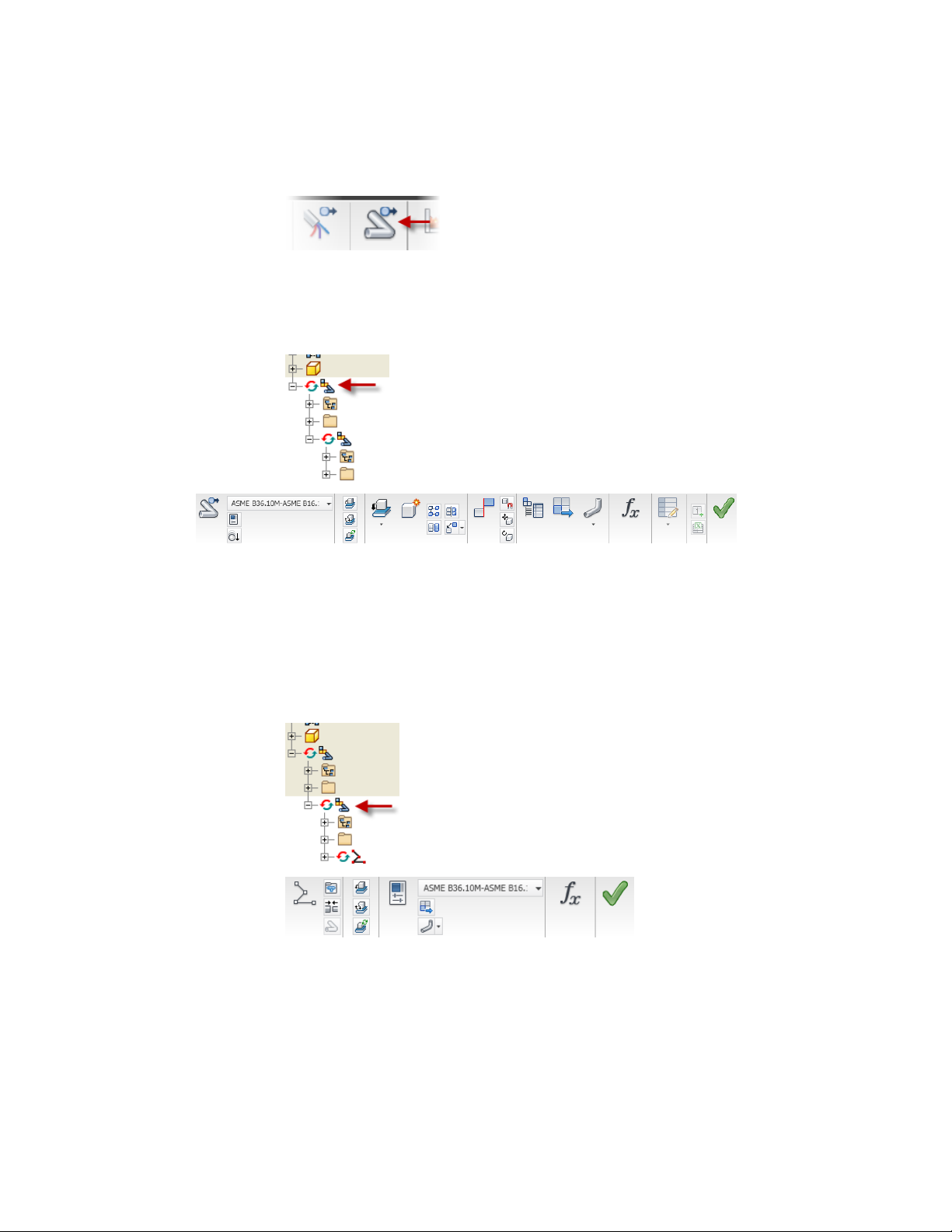
Tube and Pipe
Once you add your first run, the commands specific to creating tube and pipe
runs in an assembly are displayed.
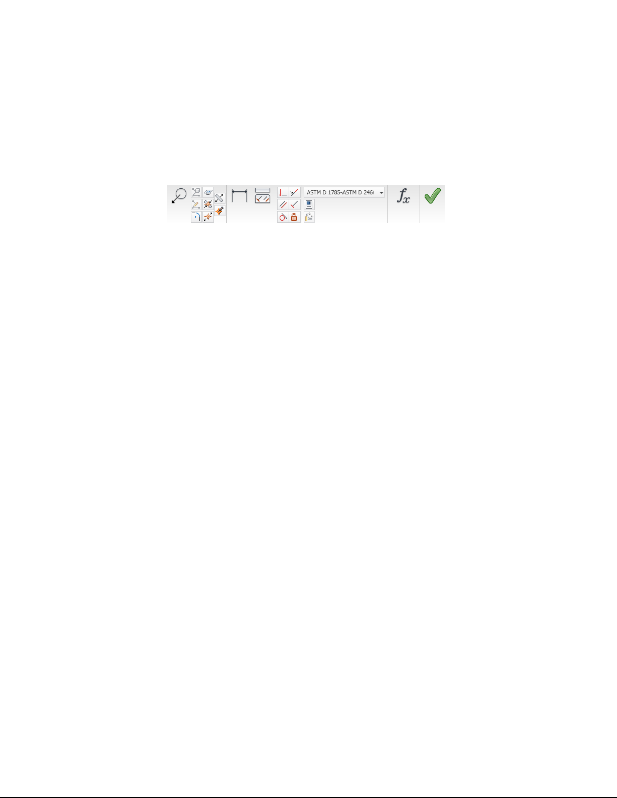
The Tube and Pipe panel is active when the top-level (master) run is active as
shown in the following image.
Use the Tube and Pipe panel to add new individual runs to the master runs
assembly, define tube and pipe styles, set Gravity, and output the ISOGEN
data.
Use the tabs to switch between the Tube & Pipe and the Assembly panel bars.
The Pipe Run tab is active when an individual run is active as shown in the
following image.
Pipe Run
Tube & Pipe Environment | 5
Use the Pipe Run tab to add new routes, place and connect fittings, define
tube and pipe styles, and output the ISOGEN data.
The Route panel is available when the tube, pipe, or hose route environment
is active.
Route
Use the Route panel to create new routes, create a derived route, add or move
sketch nodes and segments, define tube and pipe styles, and dimension or
constrain the route.
There are several ways to enter the route environment, such as creating new
routes in a pipe run, double-clicking an existing route, and right-clicking a
route and selecting Edit.
There are additional tube and pipe commands contained here:
Browser toolbar
Model browser
Part Features panel
Tube & Pipe Browser
All tube and pipe components added to an assembly are contained in the
main runs subassembly. The components include individual runs and their
associated routes, fittings, segments, and route points.
Each run contains an Origin folder, one or more routes, and any segments or
fittings that are populated or manually inserted.
Routes contain the designated route points. To become familiar with the
various components in the browser, open a sample tube and pipe assembly.
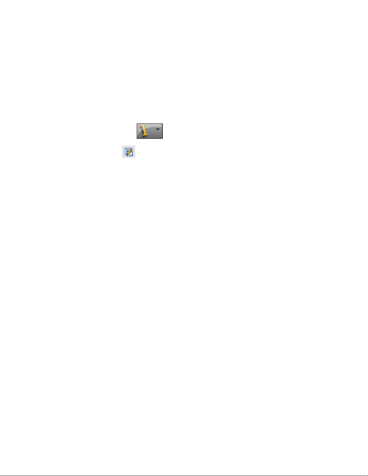
Enables switching between the Model browser, Content
Center Favorites, and Representations.
Contains the content of the tube and pipe assembly
in a hierarchy, along with the main Tube & Pipe Runs
subassembly. The main run acts as a container for all
routes and runs and the components created or placed
in the routed system.
Contains the Tube & Pipe Authoring command to author tube and pipe iParts and normal parts for publishing to the Content Center.
6 | Chapter 1 Get Started with Tube & Pipe
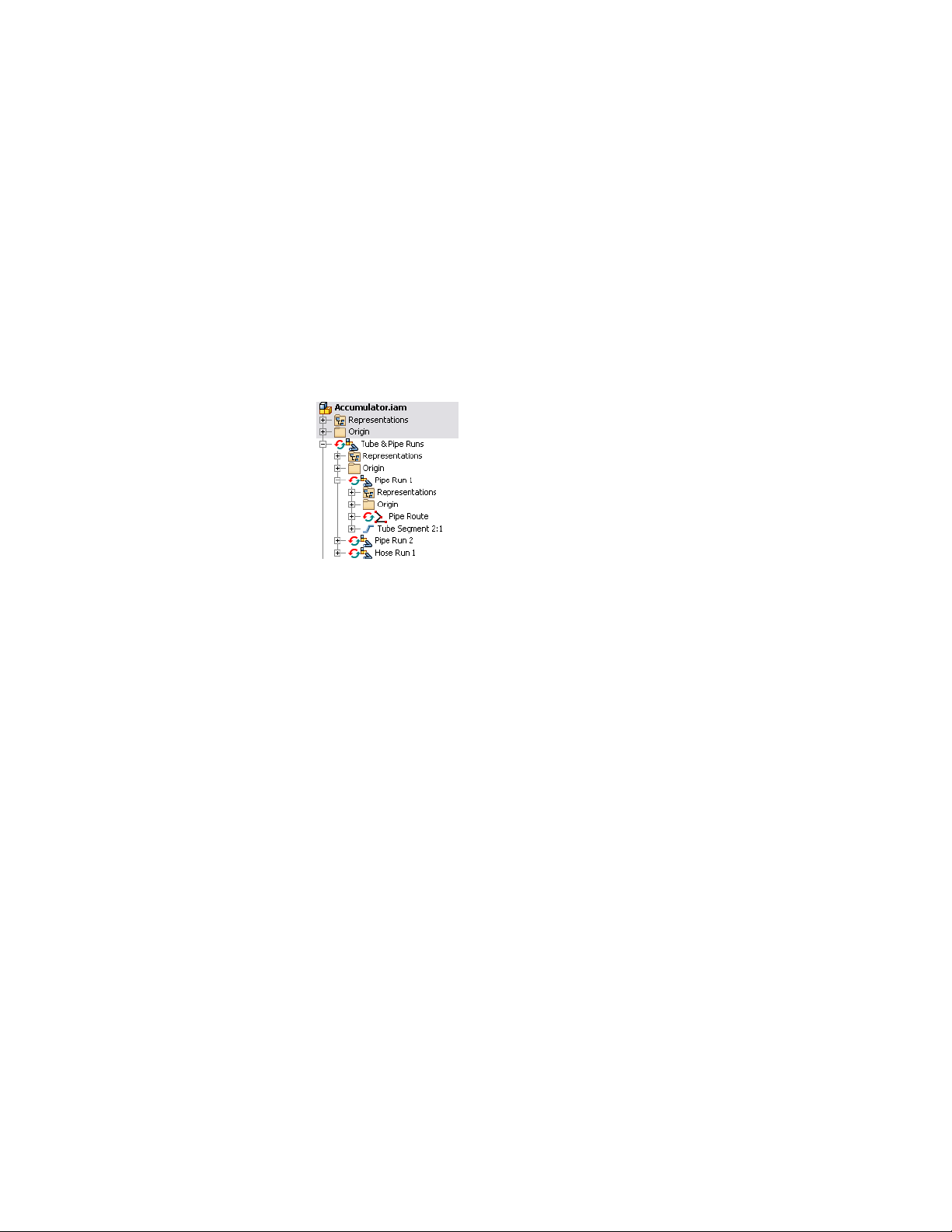
Use the Tube & Pipe Browser
1 Open the tube and pipe assembly, Accumulator. By default, it is located
at: Windows®XP C:\Program Files\Autodesk\Inventor<version>\Tutorial
Files\Tube & Pipe\Accumulator
Windows Vista
C:\Users\Public\Documents\Autodesk\Inventor<version>\Tutorial Files\Tube
& Pipe\Accumulator
2 Activate and expand the master runs assembly Tube & Pipe Runs.
Pipe Run 1 contains components for a bent tubing style run.
3 Expand Hose Run 1 to view components for a flexible hose style run.
4 Continue to expand folders in the hierarchy until you are familiar with
the contents, and then close the assembly.
®
5 To view components for a rigid pipe run, open the sample, Buffer Prep
Skid. By default, it is located at: Windows XP C:\Program
Files\Autodesk\Inventor<version>\Samples\Models\Tube & Pipe\Buffer Prep
Skid
Windows Vista
C:\Users\Public\Documents\Autodesk\Inventor<version>\Samples\Models\Tube
& Pipe\Buffer Prep Skid
6 Expand the folders in the hierarchy until you are familiar with the
contents, and then close the assembly.
Work in Autodesk Inventor Installations
If Autodesk Inventor Tube & Pipe is not installed on the system viewing the
tube and pipe data, the master runs assembly and all that it contains is
read-only. This means that the outline of the tube and pipe component is
Work in Autodesk Inventor Installations | 7

visible through Autodesk Inventor, but the component cannot be edited, and
new tube and pipe components cannot be added.
When the Tube & Pipe add-in is not installed, the tasks you can perform with
the tube and pipe data include:
■ Open a Tube & Pipe Runs subassembly.
■ Determine interferences with tube and pipe components in populated
routes by selecting the entire tube and pipe runs subassembly in the
browser.
■ View the outline of tube and pipe run data within the context of an open
assembly file.
■ Turn visibility off to completely hide the Tube & Pipe Runs component
in the graphics window.
■ Create detailed drawings of populated routes within any file.
Prerequisites
It is assumed that you have a working knowledge of the Autodesk Inventor
interface and tools. If you do not, use the integrated Help for access to online
documentation and tutorials.
At a minimum, you should understand how to:
■ Use the assembly, part modeling, sketch, and drawing environments, and
browsers.
■ Edit a component in place.
■ Create, constrain, and manipulate work points and work features.
■ Set color styles.
■ Use Content Center.
Be more productive with Autodesk® software. Get trained at an Autodesk
Authorized Training Center (ATC®) with hands-on, instructor-led classes to
help you get the most from your Autodesk products. Enhance your productivity
with proven training from over 1,400 ATC sites in more than 75 countries.
For more information about training centers, contact atc.program@autodesk.com
or visit the online ATC locator at www.autodesk.com/atc.
8 | Chapter 1 Get Started with Tube & Pipe

It is also recommended that you have a working knowledge of Windows XP,
or Windows Vista, and a working knowledge of concepts for routing tube and
pipe through mechanical assembly designs.
Back Up Tutorial Data Files
For each exercise in this section, you use files that contain the example
geometry or parts for that task. These files are included in the Tutorial Files
directory for the application. For Tube & Pipe, the files are located in the
installation path of Autodesk Inventor Tube & Pipe by default:
■ Windows XP C:\Program Files\Autodesk\Inventor <version>\Tutorial
Files\Tube & Pipe
■ Windows Vista C:\Users\Public\Documents\ Autodesk\Inventor
<version>\Tutorial Files\Tube & Pipe
Before you begin the exercises, back up the files so the originals are always
available. You can revert to these files if you make any mistakes during the
exercises, or if you would like to repeat an exercise.
Back up the tutorial files
1 Go to the Tube & Pipe directory and create a new folder called
Exercise_Backup.
2 From within the Tutorial Files directory, copy the exercise data into your
new folder.
Now you can use the files in the Tutorial Files directory as you work through
the exercises in this book. Keep any files you create for an exercise in the
Tutorial Files directory to avoid the possibility of file resolution problems.
Workflow for Tube and Pipe Assemblies
The first step in creating a tube and pipe system is to open an assembly file.
The assembly file can be empty or contain an assembly model. You can then
create the first pipe run and begin adding bent tubing, rigid piping, and flexible
hose routes.
Back Up Tutorial Data Files | 9

Create a tube and pipe runs assembly
1 Set up the project environment such as project type, workspace, and
permissions to the style library. Content Center configuration is also
especially important.
2 Optionally, customize your own master runs assembly template.
3 Within a normal Inventor assembly, create a master runs assembly.
4 Use the Tube & Pipe Styles tool to set style options.
5 Select a tube, pipe, or hose style, and then create a new route using
automatic solutions and parametric regions to guide your selections.
6 Adjust the route to design changes.
7 Populate the route or insert additional fittings into the tube and pipe
assembly or directly onto a route. Fittings can be used to initiate new
routes.
8 Add additional routes and runs.
9 Make final adjustments to each route and run. Change the active style
or add, remove, reposition, and replace fittings, route points, and
segments.
10 Populate selected route(s).
11 Optionally:
■ To reuse the master runs assembly, runs, routes, or flexible hose
assemblies, place secondary occurrences and use the Make Adaptive
tool to transition them to new primary occurrences.
■ Create Level of Detail representations to save memory if you are
working with a large assembly.
■ Create drawing views based on specific representations and
configurations, create and export bill of material tables for routes and
runs, and annotate drawings using parts lists, piping styles, and so
on.
■ Save the file in a different format such as ISOGEN or bend table to
import to other drawing applications.
10 | Chapter 1 Get Started with Tube & Pipe
Set Up Projects For Exercises
For the exercises, browse to and select the project file in the Tutorial Files
directory.
Set up the project for Tube & Pipe exercises
1 Click ➤ Manage ➤ Projects.
2 Use the Configure Content Center Libraries tool to configure
libraries. If required, ensure that you have logged in to your Autodesk
Vault server and the needed libraries are ready on the server.
3 Select the AirSystemAssy.ipj as the active project.
4 Optionally, in the Edit Project pane, right-click Use Styles Library, and
then select Yes or Read Only.
5 Optionally, expand the Folder Options, right-click Content Center Files,
select Edit, and then enter CC.
The CC folder is under the root path of the project work space. You can
specify any other location you need to store the Content Center library
content. You can also use the default Content Center Files location.
6 When you have completed all settings for the project, click Save.
7 Ensure the project is active. If it is not, double-click the project.
8 Click Done.
Define the Master Runs Assembly
When an assembly file is first opened, the assembly environment is displayed
and you can begin adding pipe runs. For the first pipe run added, the system
creates the master runs assembly along with an individual run. The master
runs assembly is a container for all pipe runs added to the assembly. The
number of runs you include depends on your design and manufacturing
documentation needs.
Each run can include one or more individual routes. All routes in a run can
use the same or different styles. With the capability to assign unique styles,
it is possible to have all three route types, each with different size diameters
Set Up Projects For Exercises | 11
in a single run. Routes can start and end on assembly model geometry or an
initial fitting dropped on the route to create a branch or fork.
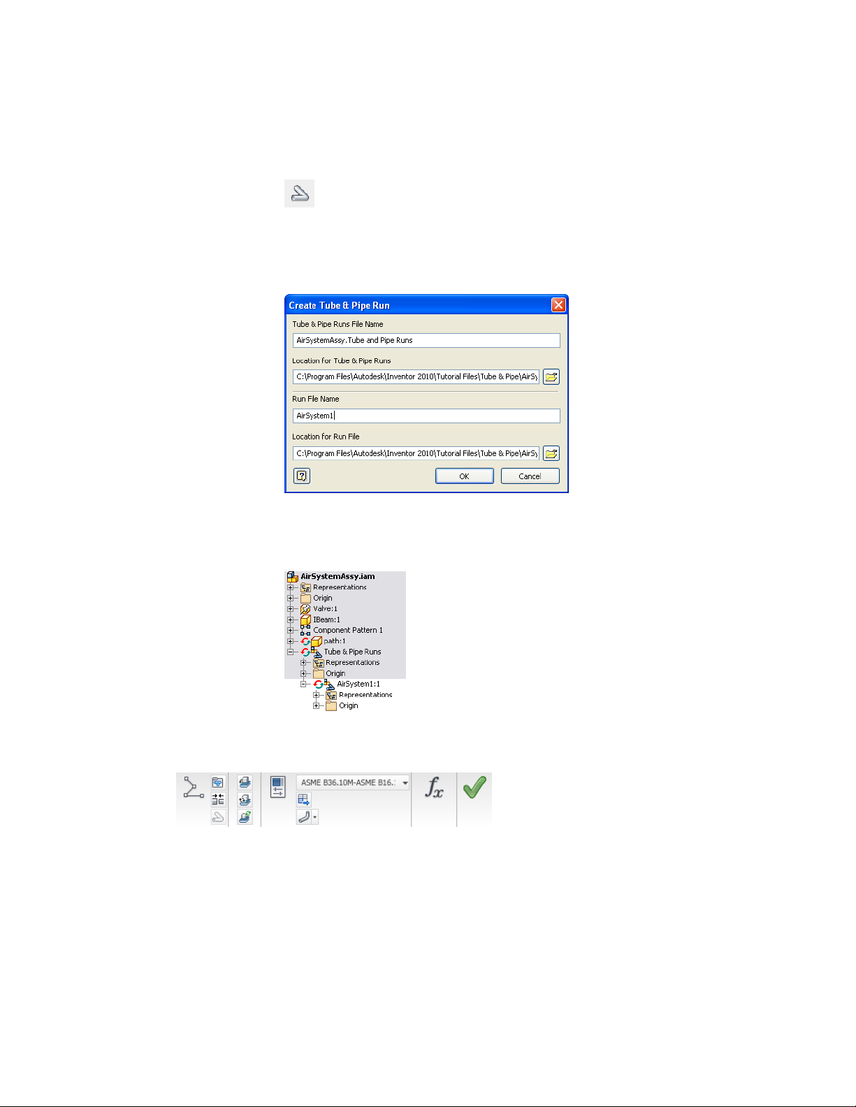
Create Master Runs Assemblies
To create the master runs assembly, you click Environments tab ➤ Begin
panel ➤ Tube and Pipe on the ribbon. On the Create Tube & Pipe Run dialog
box that appears you provide a unique name and location for the master runs
assembly and individual run respectively. By default, the files are saved to the
workspace of the active project.
The Tube & Pipe Runs assembly is added to the browser along with other
placed components and is arranged in the order it was added to the assembly.
In the following exercise, you open an existing assembly and prepare to add
tubing and piping in the context of that assembly. You also become familiar
with the components included in the tube and pipe design environment
including the Tube and Pipe tab, Pipe Run tab, Route tab, and Model browser.
Create a tube and pipe assembly
1 Click ➤ Open.
2 Open the AirSystemAssy.iam assembly.
12 | Chapter 1 Get Started with Tube & Pipe
3 On the ribbon, click Environments tab ➤ Begin panel ➤ Tube
and Pipe.
4 On the Create Tube & Pipe Run dialog box, enter AirSystem1 as the name
for the first run and accept the other defaults. Verify the default path in
the project workspace.
5 Click OK.
The individual run is automatically added and activated so you can begin
defining a route and adding components.
6 Examine the available tools on the Pipe Run tab, as shown in the
following image.
7 Examine the Pipe Run tab to see the New Route tool, the Display All
Objects/Display Route Only tool, and the Active Style list.
Create Master Runs Assemblies | 13
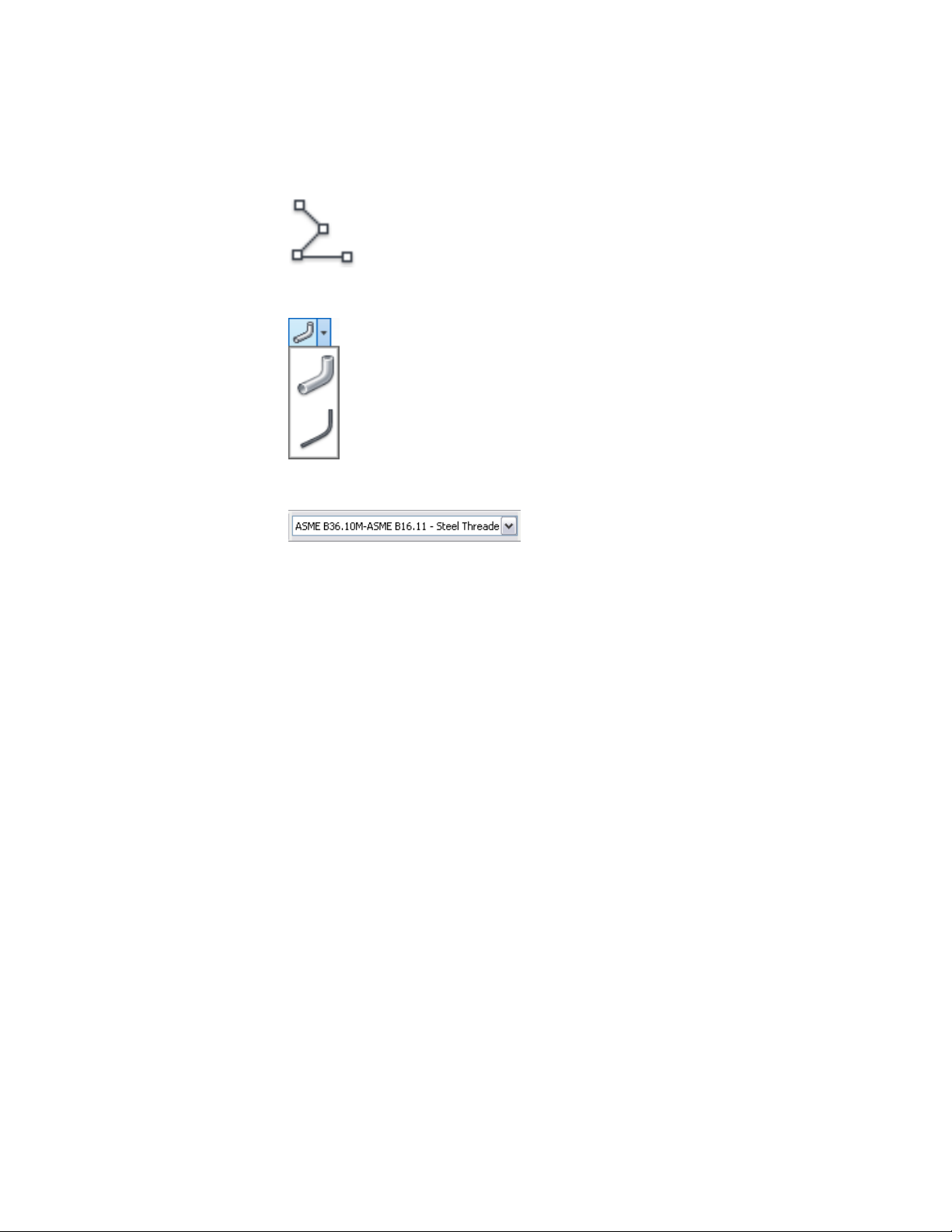
New Route
Display All Objects/Display Route Only
Active Style list
8 Click Help ➤ Help Topics to access Help, and then click the Contents
tab to display the table of contents if it is not already displayed.
9 Click Tube and Pipe to display and examine the related Help topics.
14 | Chapter 1 Get Started with Tube & Pipe
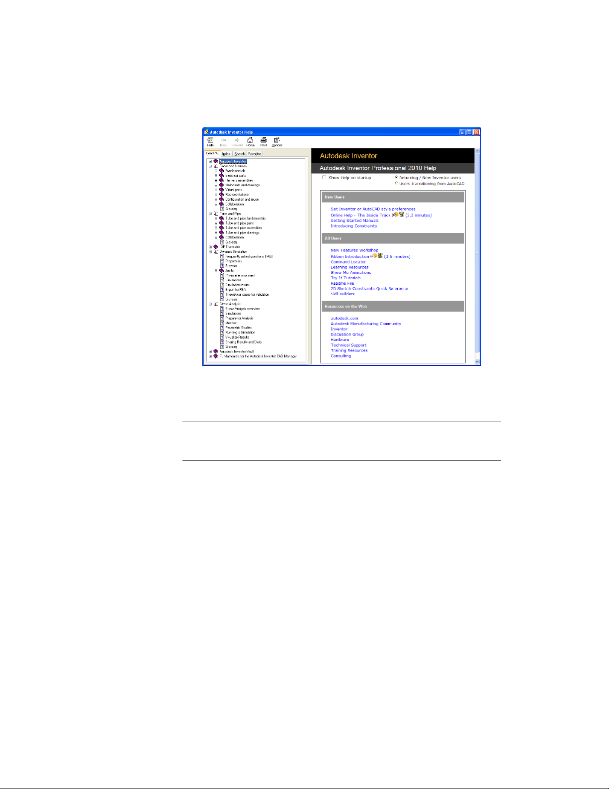
10 Close the Help window.
11 Activate the top-level assembly and save the file.
NOTE It is recommended that you save the top assembly regularly. Tube and Pipe
components are not stored in your project workspace until the top assembly is
saved.
Add Individual Runs
Each time you use the Create Pipe Run tool after the Tube & Pipe Runs
assembly is created, an individual run is added to this container run. Individual
runs are arranged in the order they are added to the tube and pipe assembly.
You can name and locate each run file as it is added.
The following image shows the default settings when you create the second
run:
Add Individual Runs | 15
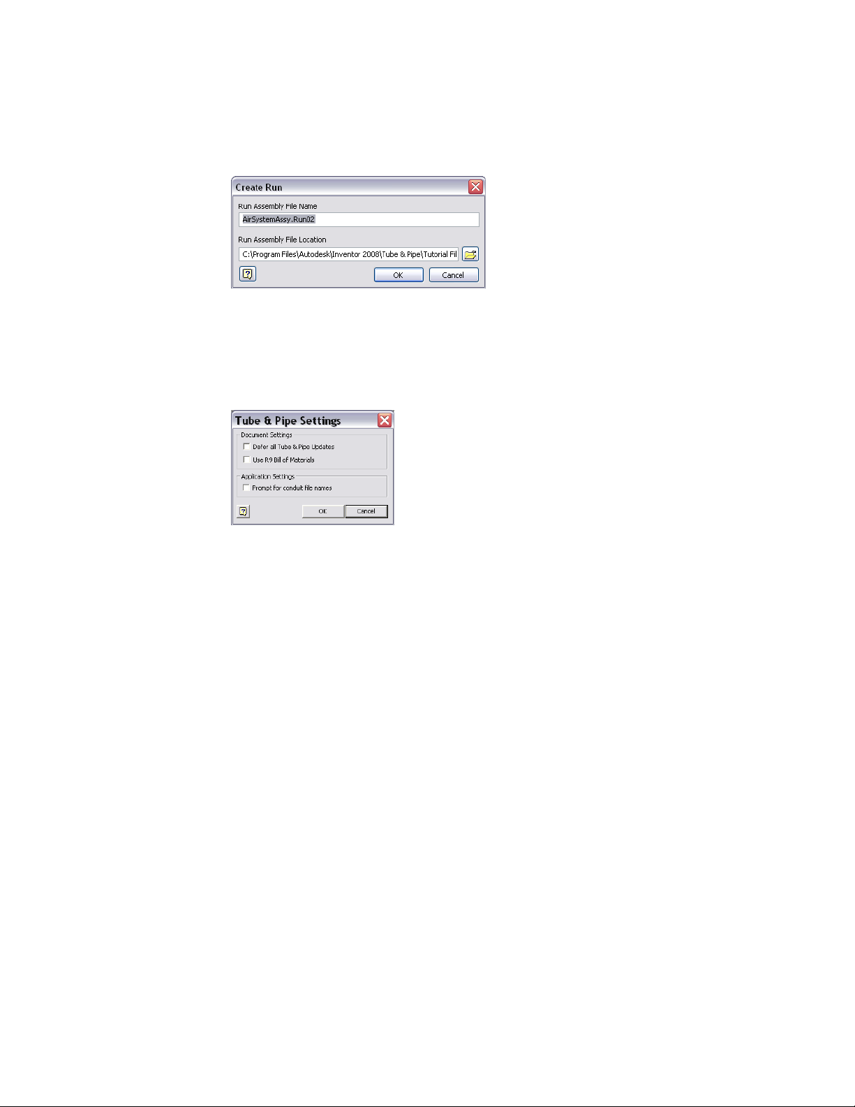
Specify Global Settings
With the top assembly active, right-click Tube & Pipe Runs in the Model
browser and use the Tube & Pipe Settings dialog box to specify the global
document and application settings for the master runs assembly.
Defer All Tube & Pipe Updates
Defer all tube and pipe updates when you are editing normal parts in a standard
Autodesk Inventor assembly or editing positional representations.
After the Defer All Tube & Pipe Updates check box is selected, most commands
specific to Tube & Pipe are disabled. The tube and pipe runs assembly is not
visible. Neither the tube and pipe runs assembly nor the associated parts in
drawings automatically update. You cannot create new pipe routes and runs
in the tube and pipe runs assembly.
When the Defer All Tube & Pipe Updates check box is cleared, you can defer
updates for individual runs and individual routes. For detailed instructions,
see Control Individual Settings on page 117 in Chapter 6.
Specify the setting for defer all tube and pipe updates
1 Activate the top assembly.
2 Right-click Tube & Pipe Runs, and select Tube & Pipe Settings.
16 | Chapter 1 Get Started with Tube & Pipe

3 In the Tube & Pipe Settings dialog box, ensure the Defer All Tube & Pipe
Updates check box is cleared.
You can view automatic responses to edits on the tube and pipe assembly.
4 Click OK.
Use of Bill of Materials
The drawing manager uses the current bill of materials (BOM) to create tube
and pipe drawings. When you migrate R9 or earlier tube and pipe drawings,
you can specify whether to continue using the R9 BOM (default) or to use the
current BOM.
The BOMs mainly differ in how they store the raw material description for
library parts:
■ In the current BOM, the raw material description for conduit parts is stored
in the new stock number property. All BOM items with the same part
number are automatically merged in parts lists. If the part number is blank,
parts do not merge.
■ In the R9 BOM, the raw material description for conduit parts was stored
in the part number property. You had control over the merging of rows
in the parts list. Even if two pipes had the same part number, you could
choose not to merge them.
In the exercises that follow you use the current version of Autodesk Inventor
Tube and Pipe to create tube and pipe assemblies, so the Use R9 Bill of Materials
check box is cleared by default.
NOTE For more information about how to migrate legacy tube and pipe drawings
to the current version, see the Help.
Prompt for Conduit File Names
When conduit parts are saved to your project workspace the first time, the
default file names are used, with a suffix of a 13-digit number that is generated
randomly based on your system time. The conduit file naming convention
can be customized when you enable the Prompt for Conduit File Names option.
Specify Global Settings | 17

Specify the prompt for conduit file names
1 Activate the top assembly or master runs assembly.
2 In the Model browser, right-click the Tube & Pipe Runs and select Tube
& Pipe Settings.
3 In the Tube & Pipe Settings dialog box, Application Settings pane, to
accept the default conduit part file names, clear the Prompt for Conduit
File Names check box. Otherwise, select the check box.
4 In the exercises that follow you do not need to customize the conduit
file names, clear the check box.
5 Click OK.
18 | Chapter 1 Get Started with Tube & Pipe

Route Basics
2
A run is a collection of one or more routes with the same or unique styles that work together
to make up a complete flow system. A route is the path that determines the shape of the flow
system within the assembly and the intelligent placement of library components for the run
along that path.
Some routes contained in a run start and end on the assembly model geometry. Other routes
branch off a primary route to create a network of interconnecting rigid pipes, bent tubes, and
flexible hoses required to represent a single flow system.
Once you have a route, you can populate it with the Content Center library content based
on the tube and pipe style and the defined route path through the assembly.
About Rigid Routes
There are two types of rigid routes: rigid piping and bent tubing. The rigid route
styles, Rigid Pipe with Fittings and Tubing with Bends, contain the rules for
conduit parts and elbows. A pipe route can comprise pipe segments, couplings,
45-degree and 90-degree elbows, gaskets, gaps for groove welds, and custom
bends. A tube route comprises tubing segments and tubing bends. Couplings
connect straight segments and elbows or bends connect each directional change
point. If a butt weld style is active and gaps are set to display, straight segments
and directional change points have gaps between them for groove welds instead
of fittings.
A rigid route can be a series of auto regions and parametric regions:
■ An auto region is created by selecting circular openings and work points as
the start and end route points and can have any number of segments that
are automatically created by the system. As you select two circular openings,
vertices, and work points, the system automatically generates the needed
segments and route points. If more than one routing solution exists based
19

on the points selected, you can cycle through the solutions and select the
one that best fits your needs.
■ A parametric region is created using the 3D Orthogonal Route tool along
with the 3D sketch route tools, such as Point Snap, Rotation Snap, Parallel
With Edge, Perpendicular To Face, Bend, and General Dimension.
Auto regions are created where geometric constraints are not important.
Parametric regions are created to constrain the route to existing geometry or
dimensions. An auto region can be converted to a series of continuous sketched
segments at a later time.
Auto Route Cycling
As you select existing valid geometry, the system may calculate more than
one auto region solution based on the points selected and display the Select
Other tool. You can cycle through the solutions upon route creation or later
edits, and select the one that best fits your needs.
Click the arrows to cycle through available solutions. Click the middle green
button to make your selection. If there are multiple auto-route solutions in a
single route, the Select Other tool cycles through the solutions in each section
before advancing to the next section.
20 | Chapter 2 Route Basics

Solutions are evaluated and prioritized based on length and number of
segments. The length and segment information is included in a tooltip as you
consider the available solutions.
If you must switch to a new auto region solution in later edits, activate the
route environment. The Alternate Auto Solution tool is available when
right-clicking the auto region in the Model browser.
Parametric Regions
Along with the 3D Orthogonal Route tool, you can use geometric constraints,
dimensions, custom bends, point snap, and rotation snap to manually define
sketched route points.
If existing geometry such as a vertex, linear geometry, planar faces, and work
features (including work points, work axes, and work planes) can help navigate
through the route system, include them as reference geometry. You can then
apply appropriate geometric constraints and dimension constraints to define
the design.
In addition, you can draw construction lines from sketched route points and
then use the General Dimension tool to position the coplanar segment
accurately.
NOTE It is best to plan for route constraints before starting the design.
About Flexible Hose Routes
Flexible hose routes can contain up to three parts: a start fitting, a hose
segment, and an end fitting. The start fitting and end fitting for a flexible hose
must have two connection points. Flexible hose routes can also consist of only
the hose, with both fittings suppressed, or a hose with one fitting suppressed.
To provide more control over hose shape, you can insert intermediate route
points in the hose route as you create it. As you make your selections, a preview
line appears between the selected points to help you visualize the route.
Flexible hose routes can be created between standard assembly geometry or
initiated from fittings dropped onto existing routes to create a branch.
Parametric Regions | 21

Route Points
Routes are created by selecting at least two route points. Route points can be
manually defined. In rigid routes, the system may also automatically generate
route points in auto regions.
A route typically starts from:
■ Circular geometry such as a face, a hole, and cylindrical cuts
■ Work points that reside in the assembly
■ Vertices on any assembly component
■ Existing free terminal route points in the active route
■ Existing fittings
When you select circular geometry or work points, the route remains associative
to these points. If the model geometry changes, the route automatically
updates.
A variety of edit tools are available for route points on the Route tab and the
right-click context menu, depending on the specific route creation mechanism
and route type. For instance, when you are editing a rigid route, the 3D
Move/Rotate tool, Constraints tool, and General Dimension tool are applicable
to sketched route points. However, only the Move Node tool, Move Segment
tool, and Edit Position tool are applicable to auto regions where appropriate.
Rigid Route Points
Each route point in rigid routes is typically associated to a fitting with an
exception of free terminal route points. Rigid routes with a butt weld style are
also an exception. In this case, gaps can be displayed between route
components. Valid point selections are controlled by styles, connection data,
and the action being performed.
To better control the direction of a route, you can manually define any number
of intermediate route points using the 3D sketch route tools. Appropriate tools
are available to edit route points in both auto regions and parametric regions.
System-generated route points always automatically update to changes made
to the route during editing. Sketched route points in the parametric region
may also dynamically update unless they are fully constrained.
22 | Chapter 2 Route Basics

Hose Route Points
In hose routes, intermediate route points are used to control the shape of the
splines. They are not associated to any fittings. Depending on how the hose
route style defines the start fitting and end fitting, intermediate route points
can be inserted at an appropriate time.
To reposition the hose route points, you can place geometric constraints or
adjust the offset distances from existing geometry using the Redefine tool.
Editing the hose length does not impact the position of the adjacent hose
route points.
3D Orthogonal Route Tool
The 3D Orthogonal Route tool appears as soon as you begin selecting route
points in the graphics window. It contains several elements that guide selection
of valid route points.
When the 3D Orthogonal Route tool first appears, only the line extender is
displayed. With the line extender you can select points that are offset from a
selected edge. Once you select a point along the line, other elements of the
3D Orthogonal Route tool appear at the selected point.
The elements displayed are dependent on what is selected, the connection
geometry, and set styles. For example, the 3D Orthogonal Route tool includes
different elements depending on whether you are creating a pipe route with
fittings or a tube route with bends. Some elements are common to both styles.
Valid points, those that will make a connection of the allowable length, are
highlighted with a green dot as you move the cursor over the lines in the tool.
Points that do not fall within the range set by the style criteria are displayed
as a yellow x. The size of the tool can be increased if the line is not long
enough.
Tool Elements for Pipe Routing
When a rigid piping style is active and all elements are displayed on the 3D
Orthogonal Route tool, you can:
■ Rotate freely around the local axis.
■ Change direction in 90- or 45-degree increments.
■ Create points from referenced geometry.
Hose Route Points | 23

■ Select points offset from selected edges.
The different elements in the 3D Orthogonal Route tool for rigid pipes with
fittings include:
Direction axes
Rotation arrows
45-degree angle control
Shows valid direction for the next route point. Click
the line to add a node in that direction. Together with
the Point Snap tool, you can define a work point on
the axis direction from referenced geometry.
Shows the rotation possibilities for the next route point
and enables the free rotation. Together with the Rotation Snap tool, you can rotate the direction axis to an
orientation from referenced geometry.
Changes direction in 45-degree increments. This is
available only when 45-degree route direction is set for
the active style.
Tool Elements for Tube Routing
When a Tubing with Bends style type is active the line extender, direction
axes, and rotation arrows display along with the elements specific to creating
bent tube runs. In addition to the ability to rotate freely around the local axis,
create points from referenced geometry, and select points offset from selected
edges, you can also:
■ Change direction at any angle between 0 and 180 degrees.
■ Make precise adjustments to the included angle using the rotation arrows.
■ Change the bend radius using the radius arrows.
24 | Chapter 2 Route Basics

Change Tool Displays
Both tool color and size can be changed. Tool size is changed using the plus
(+) or minus (-) keys on the keypad. Use plus (+) to increase the size, and minus
(-) to reduce it. To adjust the colors in which the direction axes, line extender,
or tooltip are displayed, set the colors as you would other color format styles.
Set colors in the display of the 3D Orthogonal Route tool
1 Open a tube and pipe assembly file containing at least one route. You
can use the Tube & Pipe sample files, which are installed in
Autodesk\Inventor <version>\Samples\Models\Tube & Pipe by default.
2 Activate the top-level assembly or Tube & Pipe Runs subassembly.
3 On the ribbon, click Manage tab ➤ Styles and Standards panel ➤ Styles
Editor .
4 In the Styles and Standards Editor dialog box, expand Color in the left
pane and select a Route_UI_Tool_(toolname) color style.
5 Set the appropriate color attributes.
6 Click Save to apply color changes immediately. Otherwise, colors become
effective when you click Done to close the dialog box.
Define Angular Position and Rotation Snap
The rotation arrows and direction axes can be displayed when defining routes
and placing fittings, and then again when editing and repositioning routes
Change Tool Displays | 25

and fittings. With the Rotation Arrows and Direction Axes displayed, you can
view the rotation possibilities for the current selection.
To rotate freely around the axis, click and drag the Rotation Arrow as needed.
To snap the rotation in 90-degree increments, click on a line of the Direction
Axis.
The tool snaps to all four quadrant border angles as you rotate. The tool also
snaps to edge or face geometry. In this case, a dashed line and preview point
show how the snap is applied.
Click and drag a rotation arrow.
Release the cursor in the new location.
Define 45-degree Angles
When the 45-degree route direction is set in the active style, the Angle Control
can be displayed in the 3D Orthogonal Route tool. When it is displayed, you
can rotate the route position in 45-degree increments.
To use the Angle Control, click the arrow pointing in the angular position
you need. When you are satisfied with the position, select a point on the line
to create a segment at the new angular position.
Click an arrow to direct the path to the angle you want.
26 | Chapter 2 Route Basics

The route path changes to the new angular position. If you select the wrong
direction, click the single arrow displayed on the selected axis to revert to the
previous angular position.
Define Bent Tubes Angles
When a tubing with bends style is active, the Rotation Handles are displayed
on the 3D Orthogonal Route tool. When they are displayed you can create a
bend at any angle.
To use the Rotation Handles click the arrow pointing in the angular position
you need, and drag to the required position. The tool snaps in regular
increments based on the 3D Angle Snap value. This value is set on the Tools
tab ➤ Options panel ➤ Document Settings ➤ Modeling tab.
Define Bent Tubes Angles | 27

When you are satisfied with the new position, select a point on the line to
create a segment at the new location. The route path changes to the new
angular position. Using the Rotation Handles, you can also create a series of
bends to achieve a compound bend.
Use Point Snap to Define Points
When the 3D Orthogonal Route tool is active and Point Snap is checked in
the context menu, you can define points by snapping to other model geometry.
Pause your cursor over faces, edges, or work points, a dashed line and preview
point are displayed at the intersection of the line and the plane of the
highlighted edge or face.
The dashed line represents the snap point in relation to the highlighted
geometry. When the preview point is displayed at the needed location, click
the selected geometry and the point is created.
28 | Chapter 2 Route Basics

A dashed line shows the point snapped from the face.
Click the face to create the route point at the intersection with the tool.
Enter Precise Values
Although all route points can be selected interactively, sometimes exact values
are needed to create the required route. You can enter precise values for both
angles and distances. The values entered are the distance or angle from the
active position to the current node. If a point was snapped onto a line of the
3D Orthogonal Route tool, the value entered is the distance from the snap
point to the desired node to add. The entered values must comply with set
rules for segment length; otherwise, you are prompted to reenter the value.
For tubing with bends styles, you can also enter a precise bend radius.
To enter an exact distance, start typing the value while your cursor pauses
over the direction axis of the 3D Orthogonal Route tool. You can also
right-click and select Enter Distance to enter a value.
Entering angles is very similar. To enter an angle, start typing the needed value
while your cursor pauses over a rotation arrow or bent tube rotation arrow.
You can also right-click and select Enter Angle to enter an angle.
Enter exact distances while your cursor pauses over the rotation arrows,
rotation arrows, or direction axes of the 3D Orthogonal Route tool.
Enter the value for the distance.
Enter Precise Values | 29

Enter the value for the angle.
To view the current bend radius, pause your cursor over the radius arrow.
Click the tool to enter a different value for the bend radius. You can also start
typing the new value while your cursor pauses over the radius arrow.
30 | Chapter 2 Route Basics

The new radius affects only the next bend. All subsequent bends use the default
radius set on the Tube & Pipe Styles dialog box.
Route Tools
To start creating routes, you must activate an individual pipe run, and then
enter the route environment. Along with the 3D Orthogonal Route tool, a
variety of sketched route tools are available and can assist in the route design.
You can create a route by connecting two or more points and directing the
route through circular openings and around existing geometry in its path.
Basic Tools
To enter the route environment, use the Pipe Run tab ➤ Route panel ➤
New Route tool.
New Route tool
In Route mode, the Route tab displays and you can begin creating a path for
your route. Use the Route tool to add new routes or continue existing ones.
Route tool
As you select points for a route, Autodesk Inventor® Routed Systems gives you
visual feedback about what is happening in the graphics window and text
messages on the status bar. The messages change based on what is selected
and the action you are performing.
When deciding on the design of your route, you can:
■ Decide whether you must manually define the route direction or allow
the system to automatically calculate solutions.
Route Tools | 31

■ Identify the circular geometry (or work points) that are used as the start
and endpoints.
■ Analyze where directional change points are needed to route through or
around existing geometry.
■ Create in-line work features, such as a work point at the intersection of
work planes, to guide the route path.
■ Place constraints or dimensions to sketched segments.
■ Convert auto regions to parametric regions so that you can make more
edits.
You can define your routes as close to the appropriate results as possible, and
then adjust them later, or you can develop them using precise distances and
dimensions as you go. To speed creation and plan for dynamic editing and
updating, allow the system to automatically create route points whenever
geometric constraints are not important. Define route points manually where
it is critical for a route to navigate through a particular direction and constrain
to existing geometry.
If using in-line work features, consider simplifying the route display by
selecting the Auto-hide in-line features option on the Tools tab ➤ Options
panel ➤ Application Options ➤ Part tab. In-line work features are hidden
as soon as they are consumed by a feature. The auto-hide option is enabled
by default.
Bend Tools
Use bent tubing and flexible hosing styles to create curved routes conforming
to the minimum bend radius. Typically, use the following tools to manually
create bends in the rigid route:
■ Custom Bend tool on the right-click context menu when the 3D
Orthogonal Route tool is active. It is applicable when creating a pipe route.
■ Bend tool on the Route tab. It is applicable when editing parametric regions
in a finished route.
32 | Chapter 2 Route Basics

Bend tool
In pipe routes, when a bend is required where it has not been manually
defined, the default bend radius of two times the pipe nominal diameter is
used. For instance, applying the Parallel With Edge tool to a certain linear
geometry may also require a bend if directional fittings in the Content Center
such as 45-degree or 90-degree elbow are not appropriate.
NOTE When an existing bend is deleted by mistake, use the Bend tool to create
a new bend where appropriate.
Dimension Tools
In rigid routes, there are three typical types of dimensions pertaining to the
route sketch:
■ Linear dimension, such as the length of route segments
■ Radial dimension, such as bend radius for custom bends in piping routes
and normal bends in tubing routes
■ Angular dimension, such as angles between directional turns
Dimensions only apply to the route sketch in parametric regions. Auto regions
always dynamically update to assembly changes so the number of segments
typically varies from the new solution. They do not involve dimensions until
the Convert to Sketch command is applied.
The Auto-Dimension tool on the right-click context menu enables you to
switch whether to automatically dimension the subsequent route sketch. To
place and edit dimensions manually, click Route tab ➤ Constrain panel ➤
Dimension or double-click an existing dimension in place.
General Dimension tool
Dimension Tools | 33

Similar to Autodesk Inventor, dimensions on the route sketch can be
categorized into two types: normal sketched dimension (driving dimension)
and driven dimension. Normal sketched dimensions are used to drive the
route geometry. For instance, sketched route segments are manually created
using a specified dimension. Driven dimensions are enclosed in parentheses
as displayed in the graphics window and allow route geometry to dynamically
respond to associated changes.
NOTE The General Dimension tool cannot create a bend. After you use the Bend
tool to create a bend between two coplanar segments, you can edit the bend
radius using the General Dimension tool.
Parallel and Perpendicular Tools
During forward creation of sketched route segments, use the Parallel With
Edge and Perpendicular To Face tools to reorient the axis of the 3D Orthogonal
Route tool against existing geometry. When the next route point is defined
on this axis, a parallel or perpendicular constraint is added to the resultant
route segment. You can also pick up route points in the other two axes.
Applying the two tools may request an irregular angle (neither 45-degree nor
90-degree) at the preceding route point. Consequently, a custom bend is
created. Radius arrow and rotation arrow are available on the 3D Orthogonal
Route tool. Edit the bend radius and rotation angle as needed.
Other Tools
In addition to the 3D Orthogonal Route tool, Point Snap, Rotation Snap,
Custom Bend, Bend, General Dimension, Parallel With Edge, and Perpendicular
To Face tools that are discussed in the preceding sections, Tube & Pipe in
Autodesk Inventor Routed Systems Suite provides the following tools to define
the route sketch manually:
Constraints tool
Include Geometry
tool
34 | Chapter 2 Route Basics
Applies the 3D sketch constraints between route points,
segments, and included reference geometry, such as
Perpendicular, Parallel, Tangent, Coincident, Collinear,
and Fix.
Includes the reference geometry from the source geometry to constrain the route sketch, such as vertices,
linear edges, planar faces, and work features (work
points, work axes, and work planes).

Draw Construction
Line tool
For detailed instructions on how to use these tools, see the Help.
Creates any number of construction lines from the
sketched route point and places dimensions, typically
the included angle between the construction line and
the adjacent segment.
Other Tools | 35

36

Set Styles
3
Tube and pipe styles describe the characteristics for tube, pipe, and hose routes. These styles
are key to controlling the design of the routed system as it evolves from prototype to
manufacturing.
This chapter provides basic information about the available options, how to set them, how
to modify and change them, and how to add them to a template.
About Tube and Pipe Styles
Tube and pipe styles affect most aspects of route design from route creation and
editing to populating the route. They are used to ensure consistent application
of tube and pipe components. For example, conduit parts and fittings in a pipe
run often have certain requirements for size, route direction, and materials.
With tube and pipe styles, you can set these requirements once, and then apply
them to the design.
When defining a style, you are specifying the conduit part and fittings from
the Content Center libraries that make up the pipe run and establishing rules
to be followed during routing.
There is a list of system-supplied tube and pipe styles in Autodesk Inventor
Routed Systems. You can use one of these styles, create your own style based
on one of them, or create your own style based on published conduit parts and
fittings.
NOTE It is possible to define a style with which you are unable to create a route,
such as if you select fittings that do not have compatible end treatments. While the
Tube & Pipe Styles tool allows styles to be defined in this way, routes cannot be
created using such a style.
®
37

To correctly define new materials for tube and pipe styles, you must enable
the Use Styles Library setting for your project. For detailed instructions, see
Set Up Projects For Exercises on page 11 in Chapter 1.
WARNING Do not confuse tube and pipe styles with styles and style libraries in
Autodesk Inventor®. They are two separate, unrelated entities.
Access Tube and Pipe Styles
Before you begin working with routes and runs, examine the style settings,
and then select the style you need.
To work with styles, activate the tube and pipe environment and start the
Tube & Pipe Styles tool to display the Tube & Pipe Styles dialog box. The Tube
& Pipe Styles tool can be accessed on the ribbon or right-click menu when
you activate:
■ The master runs assembly
■ A run
■ A route
Tube & Pipe Styles tool
Existing styles are also available from the Active Style list on the ribbon.
38 | Chapter 3 Set Styles

The features in the Tube & Pipe Styles dialog box include:
Toolbar
Active Style
Styles browser
General tab
The tool set for the library that you use to create, edit,
copy, and delete one or more defined styles. Import
and export functions are also provided to bring style
definitions in and out of the local or master runs templates. Pause your cursor over the toolbar to view the
tooltips.
Displays the style used when automatically creating a
tube or pipe route and when populating a route with
library content. The style displayed is based on the
active tube and pipe environment.
Displays the list of available style types, categories, and
individual styles. By default, the browser is expanded
to the location of the active style. Expand the list to
view and select other style types, categories, and style
definitions.
Sets or displays the name and category, style type, default components, and other general characteristics of
Access Tube and Pipe Styles | 39

Rules tab
View and Select Styles
When you first open the Tube & Pipe Styles dialog box, the browser list
automatically expands to the location of the active style. The active style
displayed is dependent on the current tube and pipe environment. The active
style is displayed above the styles browser in a read-only input box. It is also
highlighted in bold in the browser list.
how routes are created for new or existing style definitions.
Sets the parameters that specify the size range for creating route segments between identified route points.
For butt welded styles it also sets gap size and display.
For flanged and butt welded styles, it indicates the type
of coupling to use.
There are three types of styles in the list:
Rigid Pipe with Fittings
Tubing with Bends
40 | Chapter 3 Set Styles
Creates a series of straight pipe segments connected
with specified fittings. The required and optional fittings vary depending on the type of rigid pipe style
being created.
Creates a single route with bends instead of fittings at
the directional change points.

Flexible Hose
An example of each is shown in the following image.
Creates a route consisting of a single hose segment that
can connect up to two fittings
The style browser also provides access to the list of all defined styles. You can
use this list to select one or more styles, and then click a tool on the toolbar
to perform various operations. You can also right-click a node to display a
context menu with additional options.
Set Style Options
The Tube & Pipe Styles dialog box has two tabs. The nodes you select in the
browser list and certain selections you make on the General tab act as filters
to drive not only the available nominal diameter values and the rules, but
also the components from which you can choose.
The parameters on each tab are described in this section.
Set Style Options | 41

General Tab
On the General tab you can set a new, unique name for a style or modify and
rename an existing one. You also specify the general characteristics of how
routes are created and select components to include in the style definition.
The components table lists a basic set of components for the style being viewed
or created. Symbols indicate whether the component is optional or required
and if there are any issues with the component. Pause the cursor over the
symbol for a description.
Right-click a row in the table to clear existing components, suppress or
unsuppress fittings, or browse for components. When browsing for
components, the Library Browser dialog box is displayed. The parts available
for selection on the Library Browser dialog box are filtered from the Content
Center based on the node selected in the styles browser and the style criteria
set on the General tab.
42 | Chapter 3 Set Styles

Rules Tab
You can also set additional filtering, such as material and industry standard
to further refine the list. The standards and materials of published parts are
listed. Use the lists to make your selections. Once the standard is selected, the
available materials for the standard are listed. When an asterisk is displayed,
the system returns all content for that setting. For example, the system allows
all (*/any) materials to appear in the results.
The Rules tab sets parameters that specify the size range for creating route
segments between identified route points. It includes the minimum and
maximum values, as well as the increment round-off value. Other settings are
specific to the type of style being created:
■ For bent tube routes, you can set the default bend radius for the bends.
Rules Tab | 43

■ For flexible hose routes, you can set a hose length round-up value and
minimum bend radius.
■ For butt welded styles, you can set the gap size for the groove welds and
whether to display the gaps in the graphics window and drawings.
■ For a combination butt welded and flanged style, indicate the style to use
at coupling points. The fitting connections are determined by the end
treatment that is set for the fitting. All other end treatment types use a gap
to join segments and fittings.
WARNING It is recommended that the minimum segment length is at least 1.5
times Nominal Diameter. Otherwise, it is more likely to cause a minimum segment
length violation if conduit segments are too small compared to Nominal Diameter.
Work with Styles
Although it is best to set styles before creating routes or placing fittings, styles
can be created at any time and style changes can be applied to new and existing
routes throughout the design process. With styles you can:
■ Set style defaults for all new routes you create.
■ Change the active style for the tube and pipe assembly.
■ Change the style for the active route.
■ Modify settings for all routes that use the same style.
NOTE You cannot apply a rigid type style to an existing flexible hose route and
vice versa. To change between a rigid style and flexible hose style, you must delete
the route and create a new one using the flexible hose style.
Before creating a new style, author necessary conduit parts and fittings and
publish them to the Content Center. They are not created automatically. Once
custom parts are authored and published, define the new style to match the
properties of published parts. For detailed instructions about authoring and
publishing, see Author and Publish on page 155.
You can modify any of the available style definitions including those that are
provided with the system. The change is saved with the style. The style change
is also applied to any route currently using that style. In the following exercises
you create new styles based on existing ones.
44 | Chapter 3 Set Styles

NOTE Before you make changes to a system style, make a copy and give it a new
name. You can then select the system style from the browser and make the
modifications.
To create a new style from a blank one, select the style type to create, and
then click New. This leaves the basic requirements for the style type as a guide,
but clears all values.
Create Rigid Pipe with Fittings Styles
When creating rigid pipe styles, the required components depend on the type
of rigid style being created.
■ Typically three compatible parts are required: a pipe, a coupling, and an
elbow. If you require both 45-degree and 90-degree elbows, four parts are
required.
■ Self Draining styles require five components: a pipe, a coupling, a 45-degree
elbow, a 90-degree elbow, and a previously published custom elbow or tee
that matches the slope angle.
■ Welded tube and pipe styles typically need two part types: a pipe and a
90-degree elbow. Butt welded styles require you to set a gap size for the
groove welds and determine whether to display the gaps in the graphics
window and drawings.
■ Flanged styles require: a pipe, an elbow, a flange instead of a coupling, and
an optional gasket.
In this exercise, you create two new rigid piping styles using existing styles as
the base.
NOTE When you switch between styles or create new styles during edits, you are
prompted whether or not to save edits. Click Yes to save edits to the current style
before proceeding or click No to proceed without saving changes to the current
style.
Create rigid piping styles
1 With the AirSystemAssy.iam assembly open, activate the master runs
assembly Tube & Pipe Runs or the AirSystem1:1 run.
Create Rigid Pipe with Fittings Styles | 45

2 On the ribbon, click the Tube & Pipe Styles tool.
3 In the style browser, select ASTM A53/A53M - ASME B16.11 Welded Steel
Pipe as the basis for the new style.
4 Click Copy.
5 From the styles browser, select the copy you just created.
6 Click Edit.
7 On the General tab, enter Welded Steel Pipe - ASTM A53/A53M - ASME B16.11
(1/4 ND) in the Name input box.
NOTE As you create new style definitions, you can also create categories in
which to organize them. Categories are optional.
8 Under Components, notice that there are 4 components included in this
style that have all been successfully selected.
9 Under Diameter, click the arrow to select a nominal diameter of 1/4 in.
from the list.
10 If desired, click the Rules tab to view the settings for minimum and
maximum values and the increment round-off.
11 Click Save.
The new style is added to the browser list, but is not set as the active style
for forward route creation.
12 To set the style as active, right-click the style in the browser list and select
Active.
13 To define the second style, make a copy of ISO 7598/ISO 49 Threaded
Steel Pipe with Iron Fittings.
14 Select and then edit the copy you just created.
15 Name the new style: Threaded Steel Pipe with Iron Fittings (1/2 ND, 90 Only).
16 Under Components, right-click the Elbow 45 row and select Clear.
17 Under Diameter, select a nominal diameter of 1/2 in.
46 | Chapter 3 Set Styles

18 Click Save.
Tubing with Bends Style
1 In the style browser, expand the Tubing with Bends style type.
2 Select ASTM B 88-ASME B16.22 Soldered Copper Tubing as the base for
the new style.
3 Copy and edit the style as you did for the previous styles.
4 Name the style: Soldered Copper Tube (1/2 ND,.5 Bend).
5 Click the Rules tab and enter a bend radius of 0.500 in.
6 Click Save.
Flexible Hose Styles
Flexible hose styles have some additional options that the other styles do not.
You can set the Use subassembly option to determine how the flexible hose
route is structured. It can be created in a flat structure, or with route
components grouped in a subassembly under the pipe run (default). Once
you create a flexible hose route, the route structure cannot be changed.
As with rigid route types, one of the first things you must do before creating
a route is to select a flexible hose style using the Tube & Pipe Styles tool. You
can create your own flexible hose style using custom fittings published to the
Content Center or select a predefined style.
Flexible Hose Style Parameters
A flexible hose style includes several parameters that are common to all three
route types. The parameters specific to a flexible hose style include:
Hose Round Up Value
Fitting Types
(On the Rules tab) Rounds the hose length up to the
first larger value, based on the specified increment. For
example, if the Hose Round Up Value is set to 0.5 in.,
the hose length of 1.4 in. is rounded up to 1.5 in.
(On the General tab under Components) Includes a
hose part, a start fitting, and an end fitting. The start
and end fittings can be suppressed using the context
Tubing with Bends Style | 47

menu from the appropriate rows in the components
table. Suppressed fittings are not included in the flexible hose route. If you suppress the start fitting, the
end fitting is automatically suppressed.
Use subassembly
For more information about parameters, see Set Style Options on page 41 in
this chapter.
NOTE You cannot apply a rigid type style to an existing flexible hose route and
vice versa. To change between a rigid style and flexible hose style, you must delete
the route and create a new one using the flexible hose style.
Determines the structure of the hose as either a flat
structure or a subassembly.
Structure Flexible Hose Routes
When defining the flexible hose style you must decide if you want the fittings
placed into either a flat structure or a subassembly.
Flat structure
Subassembly structure
The route structure used for your design is typically determined by how the
hose route parts are purchased, assembled, and represented in manufacturing
documentation such as Parts Lists and Bills of Materials (BOM).
All parts are independent components placed along
with all other components under the pipe run. There
is no subassembly.
All parts are grouped into a subassembly under the
pipe run.
Create Flexible Hose Styles
In the following exercises, you create several hose styles based on the
predefined Hydraulic Hose - Female Thread - Swivel style.
Create a Flexible Hose style with both fittings
1 In the style browser, select Hydraulic Hose - Female Thread - Swivel.
2 Copy and edit the style as you did previously.
3 Enter the new style name, Hydraulic Hose- Female Thread - Swivel (1/2 ND
2) to indicate the nominal size and two hose fittings, and click Save.
48 | Chapter 3 Set Styles

4 On the General tab, select 1/2 in from the Diameter list.
5 On the Rules tab, verify that .125 in is the Hose Round Up value.
6 Click Save.
Create a Flexible Hose style with start fitting only
1 Create another style based on Hydraulic Hose - Female Thread - Swivel
and save it as Hydraulic Hose- Female Thread - Swivel (1/2 ND 1).
2 Under Components, select the End Fitting row, right-click and select
Suppress Fitting.
3 Select 1/2 in from the Diameter list.
4 Accept the other default settings.
5 Click Save.
Create a new Flexible Hose type style with no fittings
1 Create a third style based on Hydraulic Hose - Female Thread - Swivel
and save it as Hydraulic Hose- Female Thread - Swivel (1/2 ND 0).
2 Right-click the copy and select Edit.
3 Under Components, right-click the Start Fitting row and select Suppress
Fitting.
If the end fitting is not suppressed, you are prompted that the end fitting
will also be suppressed. Click Yes.
4 Select 1/2 in from the Diameter list.
5 Accept the other default settings.
6 Click Save.
Change Styles for Existing Routes
Design needs change as the routed system evolves. With styles, you can make
subtle or dramatic changes quickly and efficiently.
For example, it is common to create routed systems using less expensive
manufacturing methods at the early design stages, then switch to the actual,
more expensive manufacturing methods at the end.
Change Styles for Existing Routes | 49

Change the style of an existing route
1 Activate the route for which you want to change the style. If desired,
open a tube and pipe assembly from the Samples directory to perform
this operation.
2 On the Route tab, Manage panel, select a new style from the Active Style
list.
The model is updated to conform to the new style. The changes are also
reflected in the browser.
NOTE When switching a route from a Tubing with Bends style to a Rigid Pipe
with Fittings style, the results may be unpredictable. You cannot switch an existing
route between the rigid piping and flexible hose styles.
Change Active Styles for New Routes
Routes in the same system often have different uses and different requirements.
To accommodate these changes, you can select a new style with the settings
needed for each different route. If you change or edit a style that is in use by
one or more routes, the style change or edits will affect all routes that use that
style.
Change the active style for new routes
1 Activate the master runs assembly or an individual pipe run.
2 On the Tube and Pipe or Pipe Run tab, Active Style list, select Welded
Steel Pipe - ASTM A53/A53M - ASME B16.11 (1/4 ND).
Add Styles to Assembly Templates
Within an Autodesk Inventor assembly, the tube and pipe runs subassembly
is created from the master tube and pipe runs assembly template, piping
runs.iam. This file is stored in the installation path of Autodesk Inventor
Professional Tube & Pipe, by default, Windows®XP C:\Program
Files\Autodesk\Inventor <version>\Design Data\Tube & Pipe and
C:\Users\Public\Documents\Autodesk\Inventor <version>\Design Data\Tube &
Pipe for Windows Vista®.
As with Autodesk Inventor assembly templates, Autodesk Inventor Professional
Tube & Pipe provides two types of units for the template: English and Metric.
50 | Chapter 3 Set Styles

When you install Autodesk Inventor Professional, your selection of default
units of measurement sets the default template used to create standard Inventor
assemblies and the default template used to create tube and pipe runs
subassemblies. For example, if you set English (Inches) as the default unit of
measurement during installation, the template in the English subdirectory is
copied to the Design Data\Tube & Pipe directory.
When you customize a set of tube and pipe styles, they are saved in the local
piping runs assembly that you name and locate when you first start your tube
and pipe assembly. To reuse them in future tube and pipe assemblies, you can
export the styles from the local piping runs assembly, and then import them
into a (blank) master runs assembly template. Once added to the master runs
assembly template, your styles can be used in other tube and pipe assemblies.
NOTE You must check the Use Styles Library option for the project. If it is set to
No, you may receive a warning message in this exercise. You must set the option
to either Yes or Read Only. Otherwise, you cannot continue defining tube and
pipe styles and populate routes in the exercises that follow.
Add custom styles to an assembly template
1 Create a new, empty assembly file.
2 On the ribbon, click Environments tab ➤ Begin panel ➤ Tube
and Pipe.
3 When prompted, save the assembly file. On the Create Tube and Pipe
Run dialog box, click OK to save the file using the defaults.
The main tube and pipe runs assembly is automatically named and
located, and the first run is activated.
4 With the master runs assembly or the first run active, click the
Tube & Pipe Styles tool. Create new styles, modify existing styles, or
import styles as required. Save the changes and then click OK.
5 Right-click and select Finish Edit.
6 Activate the master runs assembly, right-click the individual run Run01,
and then select Delete Run.
7 Click OK to confirm.
Add Styles to Assembly Templates | 51

8 With the top assembly active, save the file.
9 In the graphics window right-click and select Generate Tube & Pipe
Template.
The piping runs.iam file is created in the Design Data\Tube & Pipe directory
along with a backup of the original template. The file name for the backup
is piping runs-old(1).iam where 1 is an incremental number starting with
1. The default installation location for Windows XP is C:\Program
Files\Autodesk\Inventor <version>\Design Data\Tube & Pipe. The default
installation location for Windows Vista is
C:\Users\Public\Documents\Autodesk\Inventor <version>\Design Data\Tube
& Pipe.
52 | Chapter 3 Set Styles

Create Rigid Routes and Runs
Rigid routes are defined by selected route points. The rigid route styles, Rigid Pipe with Fittings
and Tubing with Bends, contain the rules for route components such as conduit parts and
elbows. Couplings, welds, or flanges connect straight segments. Elbows, bends, welds, or
flanges connect each directional change point. A populated route is created based on the tube
and pipe style and the defined route path through the assembly.
In this chapter, you learn about the methods and tools for creating rigid piping and bent
tubing routes with auto regions and parametric regions, and populating selected routes with
library components.
4
Workflow for Rigid Routes
The following is a typical workflow of creating a rigid route with a mixed set of
auto regions and parametric regions.
Create a rigid route
1 Start with a tube and pipe assembly.
2 With the top assembly or master runs assembly active, right-click the master
runs assembly, Tube & Pipe Runs by default and select Tube & Pipe Settings
to set the global document settings and application settings for all routes
and runs.
3 On the ribbon, click Environments tab ➤ Begin panel ➤ Tube
and Pipe to add new runs.
53

4 If pipe run is not activated, right-click the pipe run and select Edit.
5 Select an active tube and pipe style. Optionally, you can create
new styles, modify existing styles, and import styles from other routes
or tube and pipe assemblies using the Tube & Pipe Styles tool.
6 With the pipe run active, click Pipe Run tab ➤ Route panel
➤ New Route. Enter a new file name or modify the default file name
and location.
7 On the ribbon, click Route tab ➤ Create panel ➤ Route to
start defining the start point on valid geometry.
8 Use the 3D Orthogonal Route tool to continue selecting valid geometry
to create auto route regions, or use geometry constraints, point snap, or
specific dimensions to create sketched route segments.
9 Right-click and select Finish Edit.
10 Populate the route, and set the conduit part file names if you have enabled
the Prompt for Conduit File Names option on the Tube & Pipe Settings
dialog box in Step 2.
11 To continue editing the route, if you are working with a large tube and
pipe assembly, use the Display/Update Settings and Defer All Updates
tools to prevent automatic updates and save memory cost.
12 Optionally:
■ Add additional route points as you create or edit a route.
■ Adjust route points and segments dynamically or by placing geometric
constraints and dimensional constraints.
■ Change the active tube and pipe style.
■ Place fittings and conduit parts from the Content Center using
AutoDrop or from the active project workspace.
54 | Chapter 4 Create Rigid Routes and Runs

■ Connect fittings, routes, runs, tube and pipe subassembly, and
Autodesk Inventor® components.
■ Use the Model browser to visualize the tube and pipe run structure
or change visibility for conduit parts and fittings.
13 Save the top assembly.
It is recommended that you save the top assembly regularly. Tube and
pipe components are not stored in your project workspace until the top
assembly is saved.
Create Auto Route Regions
In this exercise, you quickly define a route by selecting points using circular
geometry and allowing the system to generate the rest.
Create an auto region
1 In the AirSystemAssy.iam assembly, activate AirSystem1:1.
2 On the Pipe Run tab active style list, verify that Welded Steel Pipe - ASTM
A53/A53M - ASME B16.11 (1/4 ND) is the active style.
3 On the ribbon, click Pipe Run tab ➤ Route panel ➤ New Route.
4 On the Create New Route dialog box, accept the default route file name
and location, and then click OK.
A pipe route is added to the active run and activated in place. The Route
tab is displayed.
5 On the ribbon, click Route tab ➤ Create panel ➤ Route.
Create Auto Route Regions | 55

6 In the graphics window, pause the cursor over the circular geometry as
shown in the following image. Zoom in and use the Select Other Direction
tool if needed to make your selection.
Once preselected, the circular geometry highlights and the line extender
displays, showing the direction of the route so you can create valid points
along the line. Press the spacebar to change the direction of the line
extender if needed.
7 Click the circular geometry to select it as the start point.
This point is associated with the component that contains the selected
circular edge. A work point is added to the piping route.
8 For the second route point, you can select a point on the line extender
or existing geometry. To route through the IBeam, pause the cursor over
the left arc of the IBeam opening.
56 | Chapter 4 Create Rigid Routes and Runs

Rotate and zoom in to view the arc. Make sure the line is pointing to the
approach direction of the route.
NOTE To flip the direction of a displayed axis, press the spacebar or use the
Select Other tool.
9 Click the geometry to select it as the second point.
As soon as you make your selection, the route generates to that point
and the Select Other tool appears indicating that multiple solutions exist.
10 Click the arrows to cycle through the solutions. Click the green middle
button to select the first solution as shown in Step 9.
11 In the Model browser, verify that the Autoroute browser node is added
and contains the indented auto route points.
Create Auto Route Regions | 57

12 Right-click the Autoroute browser node and select Alternate Route
Solution.
You can use the Select Other tool to switch the auto region solution as
needed.
13 Ensure that you click the green middle button on the Select Other tool
to go back to the previously-set solution before you continue.
Manually Create Parametric Regions
Many runs involve more complex routing, which requires the creation of
additional route points. Tube & Pipe in Autodesk Inventor® Routed Systems
provides a variety of route tools to dimension or constrain the route against
existing geometry and construction lines.
In this chapter, you learn about how to use the General Dimension tool,
Parallel With Edge, Perpendicular To Face, Point Snap and Rotation Snap,
Bend and Custom Bend, and 3D Orthogonal Route tool.
For detailed instructions about other parametric route tools, refer to the Help.
58 | Chapter 4 Create Rigid Routes and Runs

Automatically Dimension Route Sketches
When you manually define the next route point, the system automatically
adds dimensions to the route sketch by default. You can disable the
Auto-Dimension option on the right-click menu.
In the exercises that follow, you allow the system to automatically dimension
the route sketch in parametric regions so you accept the default setting.
Automatically dimension the parametric route sketch
1 In the Route1 environment, ensure the 3D Orthogonal Route tool is
active for forward creation. If the line extender is not displayed, right-click
the last route point, and click the Route tool.
2 Right-click in the graphics window and verify that Auto-Dimension is
enabled.
Automatically Dimension Route Sketches | 59

Create Segments With Precise Values
When the 3D Orthogonal Route tool is active, you can define the segments
with precise values using any of the following ways:
■ Move the cursor over the direction axis of the 3D Orthogonal Route tool,
right-click, and then select Enter Distance.
■ Pause the cursor over the direction axis, and then directly type the value
from the keyboard. The Enter Distance dialog box is automatically
displayed.
When you manually define the next route point, the system automatically
adds dimensions to the route sketch by default. You can disable the
Auto-Dimension option on the right-click context menu.
In the exercises that follow, you allow the system to automatically dimension
the route sketch in parametric regions so you accept the default setting.
Create segments using precise values
1 Ensure the 3D Orthogonal Route tool is active on the last route point.
2 Pause the cursor over the line extender, right-click and select Enter
Distance.
3 Enter a distance of 3.4 inches for the next point, and then click the green
check mark.
The point is created on the screen, and the 3D Orthogonal Route tool is
displayed again at the new point. This time, since the new point is an
arbitrary point in space, all directions are enabled and selectable, except
backwards.
60 | Chapter 4 Create Rigid Routes and Runs

Define Parallel and Perpendicular Segments
In this exercise, you reorient the direction axes of the 3D Orthogonal Route
tool parallel and perpendicular to the edges and faces on the concave path
part. The next segments can then fit in the path part.
Applying the Parallel With Edge tool to a certain linear geometry may require
a bend if directional fittings in the Content Center such as 45-degree or
90-degree elbow are not appropriate.
Create segments using existing geometry
1 Rotate your view to look at the front of the assembly.
2 Pause the cursor over the red direction axis of the 3D Orthogonal Route
tool, right-click and select Parallel With Edge.
Define Parallel and Perpendicular Segments | 61

The system prompts you to select a linear edge.
3 Select the linear edge on the path part as shown in the following image,
and click to set the selection.
The red direction axis is reoriented to the direction of the selected edge.
The included reference geometry is added to the Included Geometry
folder in the Model browser.
62 | Chapter 4 Create Rigid Routes and Runs

4 Pause the cursor over the red axis, and then enter 4.3.
5 Verify that a bend is automatically added between the new segment and
the preceding segment.
6 For the next point, right-click the red direction axis again and select
Parallel With Edge.
7 Select the other linear edge on the path part as shown in the following
image.
Define Parallel and Perpendicular Segments | 63

8 Before creating the next route point, right-click in the graphics window
and clear the Auto-Dimension check mark.
9 Click anywhere in the forward direction on the red direction axis. The
segment length is not important.
10 Right-click in the graphics window and select Done.
11 Verify that the new segment is not dimensioned.
In the exercise that follows, you make the last route point coincident with a
newly created route point. The last segment must not be dimensioned so that
it can dynamically update to a new segment length. Otherwise, the route
sketch may be over-constrained.
NOTE If you did not turn off the Auto-Dimension option, the last segment is
dimensioned. To dynamically update to later edits, you can also manually delete
the linear dimension. Right-click the dimension, and select Delete.
64 | Chapter 4 Create Rigid Routes and Runs

Snap Route Points to Existing Geometry
The Point Snap tool helps you to create route points by snapping to faces,
edges, work points, or vertices.
In this exercise, you continue defining the route point by snapping to the
path part.
Snap route points to existing geometry
1 On the ribbon, click Route tab ➤ Create panel ➤ Route.
2 Click the left circular opening on the valve part.
3 Right-click in the graphics window and select Point Snap.
4 Move the cursor over the last segment you just created in the preceding
exercise.
A dashed line representing the snap point is displayed from the cursor
to the preview point. A preview point is displayed at the intersection of
the line and the axis.
Snap Route Points to Existing Geometry | 65

5 When the lines appear, click the segment to set the snapped route point.
6 Right-click and select Done.
66 | Chapter 4 Create Rigid Routes and Runs

Place Constraints On Route Sketches
As with the 3D sketch in Autodesk Inventor, you can place geometric
constraints on the route sketch to constrain route points and segments.
Available 3D sketch constraints include Perpendicular, Parallel, Tangent,
Coincident, Collinear, and Fix. They help create your tube and pipe system
in the appropriate direction and orientation and constrain it to assembly
changes, join route points, and make route points fixed where dynamic updates
are not allowed.
In this exercise, you place a coincident constraint on the two separate route
points to join two route segments.
Join separate route points with the coincident constraint
1 On the ribbon, click Route tab ➤ Constrain panel ➤
Coincident.
2 Select the two separate route points as shown in the following images.
First point to select
Place Constraints On Route Sketches | 67

Second point to select
The separate sketches form a closed route.
3 Right-click in the graphics window and select Done.
4 Right-click again and select Finish Edit.
68 | Chapter 4 Create Rigid Routes and Runs

Notice that an error icon displays beside the route.
Place Constraints On Route Sketches | 69

Placing the coincident constraint causes an odd (not 90-degree, 45-degree
or combined135-degree) angle between the two segments so the route is
in error. In the exercise that follows, you create a bend to fix the violation.
Create Bends Between Existing Pipe Segments
The rigid piping styles allow only the 90-degree, and 45-degree angles (when
45-degree is allowed in the style) and also the combined angles of 135-degrees.
When the Parallel With Edge or Perpendicular To Face tool is applied, bends
are automatically created where an odd angle is required.
When an odd angle exists between the two joint pipe segments, violations
occur. Use the Bend tool to create a bend so that the route is valid.
You can manually define the bends using the Custom Bend tool. It is applied
before you create the next segment.
In this exercise, you use the Bend tool to fix the invalid angle violation in the
preceding exercise.
Join separate route points with the coincident constraint
1 To verify the errors in Route01, right-click the route in the Model browser
and select Show Violations.
2 To identify the route part in error, click an error on the Show Violations
dialog box, and then view the error in the graphic window.
The invalid angle is between the two segments as highlighted in the
following image.
3 Click OK to close the Show Violations dialog box.
70 | Chapter 4 Create Rigid Routes and Runs

4 On the ribbon, click Route tab ➤ Create panel ➤ Bends.
5 Accept the default settings on the Bend dialog box, and then select the
two segments that include the invalid angle.
The bend is created with a radius value of 0.5 inch. The error icon in the
Model browser disappears.
6 Close the Bend dialog box.
7 To end the route, right-click again and select Finish Edit.
Create Pipe Routes With Custom Bends
Rigid pipe routes with fittings may require a custom bend to satisfy special
manufacturing situations. To add a custom bend, use the Custom Bend option
in the right-click context menu while creating a pipe route. The 3D Orthogonal
Route tool changes to include the tube routing tools so you can create a bend
with the radius and angle you need. You can create multiple custom bends
in any given route.
In this exercise, you add a second route in the AirSystem1 run, change the
active style, and then create a route that is offset from the circular edge. You
also use the 3D Orthogonal Route tool to create additional points, including
custom bends.
Add custom bends
1 In the AirSystemAssy.iam assembly, activate the AirSystem1:1 run.
Create Pipe Routes With Custom Bends | 71

2 On the Pipe Run tab, Manage panel, Active Style list, set the Active Style
to Threaded Steel Pipe with Iron Fittings (1/2, 90 Only).
3 On the ribbon, click Pipe Run tab ➤ Route panel ➤ New Route, and
then accept the default route file name and location to continue.
4 On the ribbon, click Route tab ➤ Create panel ➤ Route to start defining
the start point on valid geometry.
5 Pause the cursor over the circular edge as shown in the following image,
enter a distance of 1 inch, and then click the green check mark.
The point is created offset from the circular edge by that distance.
6 Move the cursor along the line extender and enter 8.5.
You can enlarge or reduce the 3D Orthogonal Route tool by pressing plus
(Shift and +) and minus (-) on the keypad.
7 Enlarge the 3D Orthogonal Route tool until the line reaches the top of
the model.
8 Make sure Point Snap is on, and then move the cursor over the work
plane to snap the point onto the 3D Orthogonal Route tool. Click to
create the point.
72 | Chapter 4 Create Rigid Routes and Runs

9 Rotate the view to the front of the assembly.
Create Pipe Routes With Custom Bends | 73

10 Right-click in the graphics window, and select Custom Bend.
The 3D Orthogonal Route tool now displays the tube routing elements.
11 Click the rotation handle on the red axis and drag in the direction shown
until the tooltip displays an angle of 30 degrees. You can also enter 30
when you move the cursor over the rotation handle.
74 | Chapter 4 Create Rigid Routes and Runs

12 Pause the cursor over the red axis, and then enter a distance of 5 inches.
The 3D Orthogonal Route tool reverts to displaying the pipe routing
elements.
13 Right-click and select Custom Bend. Add a bend of 60 degrees in the other
direction, as shown in the following image.
Create Pipe Routes With Custom Bends | 75

14 Pause the cursor over the red axis, and then enter a distance of 5 inches.
15 Right-click, select Custom Bend, and then create a bend of 30 degrees as
shown in the following image.
76 | Chapter 4 Create Rigid Routes and Runs

16 Pause the cursor over the red axis, and enter 8 inches.
17 Right-click and select Done.
18 Right-click and select Finish Edit.
The linear segments adjacent to the custom bend sequence are joined
with the bend to create a single pipe segment with bends, rather than
custom elbows.
Create Pipe Routes With Custom Bends | 77

Create Bent Tube Routes
Bent tube type routes can be created at any angle and using any bend radius.
For this exercise you select the Soldered Copper Tube (1/2 ND,.5 Bend) style
you created earlier, and then create a bent tube route by directing it along the
IBeam and over to the threaded steel route to the right of the model.
Create a bent tube route
1 In the AirSystemAssy.iam assembly, activate the AirSystem1:1 run.
2 On the Pipe Run tab, Manage panel, Active Style list, select Soldered
Copper Tubing (1/2 ND,.5 Bend).
78 | Chapter 4 Create Rigid Routes and Runs

3 On the ribbon, click Pipe Run tab ➤ Route panel ➤ New Route, and
then accept the default route file name and location to continue.
4 On the ribbon, click Route tab ➤ Create panel ➤ Route to start defining
the start point on valid geometry.
5 Select the start point of the route.
6 Enter a distance of 5 inches for the first segment.
The 3D Orthogonal Route tool is displayed with the tube routing elements.
7 Click the Radius handle and enter a bend radius of 1 inch.
8 Rotate to get a better view of the tool, select the Rotation handle, and
then drag up by 30 degrees.
9 Pause the cursor over the red axis, and enter a distance of 3 inches.
10 Select the Rotation handle, and drag down 140 degrees.
11 Pause the cursor over the red axis, and enter a distance of 3 inches.
Create Bent Tube Routes | 79

12 Click and drag the rotation handle 15 degrees to the right, and then
create two segments of 5 inches along the red axis.
13 Rotate the view to look at the front of the model. Move the cursor over
the Rotation handle, and then enter 50 degrees to drag to the right.
14 Pause the cursor over the red axis, and then enter a distance of 21 inches
for the next route point.
80 | Chapter 4 Create Rigid Routes and Runs

15 Enter a bend radius of 2 inches, click and drag the rotation handles up
by 40 degrees, and then enter a distance of 5 inches along the red axis.
Create Bent Tube Routes | 81

16 Right-click and select Done.
17 Right-click and select Finish Edit.
Realign 3D Orthogonal Route Tool
The Rotation Snap tool assists you to reorient a specified direction axis of the
3D Orthogonal Route tool by snapping to available linear edges and planar
faces. A custom bend is automatically created at the current route point when
the next segment is defined. It is useful when the direction axes of the 3D
Orthogonal Route tool does not align with the needed geometry.
In this exercise, you create a new route with the Welded Steel Pipe - ASTM
A53/A53M - ASME B16.11 (1/4 ND) style, and then review the skills you have
learned about the Point Snap tool to create route points. Finally, use the
82 | Chapter 4 Create Rigid Routes and Runs

Rotation Snap tool on the right-click context menu to reorient the direction
axes of the 3D Orthogonal Route tool by snapping to the valve opening.
Snap the axis rotation to existing geometry
1 In the AirSystemAssy.iam assembly, activate the AirSystem1:1 run.
2 On the Pipe Run tab, Manage panel, Active Style list, select Welded Steel
Pipe - ASTM A53/A53M - ASME B16.11 (1/4 ND).
3 On the ribbon, click Pipe Run tab ➤ Route panel ➤ New Route, and
then accept the default route file name and location.
AirSystemAssy.Route04 is added to the Model browser.
4 On the ribbon, click Route tab ➤ Create panel ➤ Route to start defining
the start point on valid geometry.
5 Select the start point as shown in the following image.
6 Click the right circular edge on the IBeam to allow the system to generate
an auto region. Use the Select Other tool to cycle through all solutions
as needed, and then select the first solution.
7 Right-click in the graphics window and select Point Snap.
8 Move the cursor over the upper face on the path part as shown in the
following image, and then click to snap the new route point.
Rotate the view to get a better view as needed.
Realign 3D Orthogonal Route Tool | 83

9 Pause the cursor over the line extender, and then enter a distance of 2.25
inches for the next point.
10 Rotate to the isometric view. Notice that the green axis does not align
parallel to the valve part.
11 In this exercise, the green axis should be parallel to the valve part for the
rest of the route. Right-click in the graphics window, and select Rotation
Snap.
84 | Chapter 4 Create Rigid Routes and Runs

12 Click the Rotation handle on the green axis, and drag the cursor over the
valve opening. Release the cursor.
The green axis changes to the new orientation. It is parallel to the valve
part.
13 Right-click in the graphics window to ensure that Point Snap is enabled
on the context menu. Highlight the circular edge in the valve opening
as shown in the following image. Right-click and choose Select Other
Snap.
A preview point displays at the intersection of the line and the axis. A
dashed line representing the snap point displays from the cursor to the
preview point.
14 When the lines appear, click the green button to set the snapped route
point.
Realign 3D Orthogonal Route Tool | 85

15 For the last point, click the circular geometry.
16 Right-click and select Done.
17 Right-click again and select Finish Edit.
86 | Chapter 4 Create Rigid Routes and Runs

Control Dimension Visibility
In the route environment, dimensions in parametric regions remain visible
by default. Auto regions do not involve dimensions so no associated
dimensions are displayed.
Too many dimensions may block the view of the design window. In the
exercise that follows, you practice controlling the dimension visibility on the
route sketch using the Dimension Visibility tool.
Hide or display the route dimensions
1 Activate Route01.
2 Right-click the route in the Model browser, and then clear the Dimension
Visibility check mark.
All dimensions become invisible.
Control Dimension Visibility | 87

3 To display the route dimensions, select Dimension Visibility on the
right-click menu.
4 Right-click in the graphics window and select Finish Edit.
The run environment is activated.
NOTE In the run environment, the route dimensions are always invisible
regardless of the Dimension Visibility setting by default. To display route
dimensions in the run environment, right-click the route and select the
Dimension Visibility check mark.
Populated Routes
A populated route is a solid, three-dimensional representation of the pipes
and fittings. A route starts with a defined path, which you can populate with
library components to complete the route. You can place fittings to the
populated routes from the Content Center tool using AutoDrop.
88 | Chapter 4 Create Rigid Routes and Runs
 Loading...