

Page 1

Autodesk® Inventor® Fusion Technology Preview
Autodesk Inventor Fusion:
Getting Started
Page 2

Contents
Chapter 1 Autodesk Inventor Fusion TP2 . . . . . . . . . . . . . . . . . . . 1
What is new in TP2? . . . . . . . . . . . . . . . . . . . . . . . . . . . . 1
Working with Inventor Fusion User Interface . . . . . . . . . . . . . . . 4
The Ribbon . . . . . . . . . . . . . . . . . . . . . . . . . . . . . . 4
Display and Organize the Ribbon . . . . . . . . . . . . . . . 4
Customize the Ribbon . . . . . . . . . . . . . . . . . . . . . 5
Glyphs and Manipulators . . . . . . . . . . . . . . . . . . . . . . 6
Marking Menu . . . . . . . . . . . . . . . . . . . . . . . . . . . . 8
Selection commands . . . . . . . . . . . . . . . . . . . . . . . . 18
Enhanced tooltip . . . . . . . . . . . . . . . . . . . . . . . . . . 23
Browser and Copy/Paste . . . . . . . . . . . . . . . . . . . . . . 24
Cut/Copy and Paste . . . . . . . . . . . . . . . . . . . . . . 26
Function Key Behavior . . . . . . . . . . . . . . . . . . . . . . . 32
Triad . . . . . . . . . . . . . . . . . . . . . . . . . . . . . . . . . 33
Measure . . . . . . . . . . . . . . . . . . . . . . . . . . . . . . . 34
Menu and Command Access . . . . . . . . . . . . . . . . . . . . 36
Other commands in the Application Window . . . . . . . . . . . 37
Application Menu . . . . . . . . . . . . . . . . . . . . . . . 38
Quick Access commandbar . . . . . . . . . . . . . . . . . . 45
Status Bar . . . . . . . . . . . . . . . . . . . . . . . . . . . 46
Keytips . . . . . . . . . . . . . . . . . . . . . . . . . . . . . 46
Navigation commands . . . . . . . . . . . . . . . . . . . . 47
Navigation Bar . . . . . . . . . . . . . . . . . . . . . . . . 70
Create 3D Models . . . . . . . . . . . . . . . . . . . . . . . . . . . . . 72
i
Page 3

Create a Single Body . . . . . . . . . . . . . . . . . . . . . . . . 75
Create Multiple Bodies . . . . . . . . . . . . . . . . . . . . . . . 84
Modify a Body . . . . . . . . . . . . . . . . . . . . . . . . . . . . 93
Press/Pull Command . . . . . . . . . . . . . . . . . . . . . 94
Move Command . . . . . . . . . . . . . . . . . . . . . . . 105
Draft Command . . . . . . . . . . . . . . . . . . . . . . . 126
Sketch . . . . . . . . . . . . . . . . . . . . . . . . . . . . . . . 135
Starting a Sketch . . . . . . . . . . . . . . . . . . . . . . . 136
The Sketch Plane . . . . . . . . . . . . . . . . . . . . . . . 138
The Sketch Grid . . . . . . . . . . . . . . . . . . . . . . . 138
Line/Arc Segment Creation . . . . . . . . . . . . . . . . . 141
Spline Creation . . . . . . . . . . . . . . . . . . . . . . . 144
Circle Creation . . . . . . . . . . . . . . . . . . . . . . . . 147
Circular Arc Creation . . . . . . . . . . . . . . . . . . . . 149
Rectangle Creation . . . . . . . . . . . . . . . . . . . . . . 151
Ellipse Creation . . . . . . . . . . . . . . . . . . . . . . . 152
Polygon Creation . . . . . . . . . . . . . . . . . . . . . . 153
Project Geometry . . . . . . . . . . . . . . . . . . . . . . 157
Trim/Extend . . . . . . . . . . . . . . . . . . . . . . . . . 157
Sketch Fillet . . . . . . . . . . . . . . . . . . . . . . . . . 160
Sketch Inferencing . . . . . . . . . . . . . . . . . . . . . . 162
Sketch Constraints . . . . . . . . . . . . . . . . . . . . . . 169
Stopping a Sketch . . . . . . . . . . . . . . . . . . . . . . 171
Sketch Profiles . . . . . . . . . . . . . . . . . . . . . . . . 171
Editing a Sketch Entity . . . . . . . . . . . . . . . . . . . 172
Locking Sketch Geometry . . . . . . . . . . . . . . . . . . 176
Features . . . . . . . . . . . . . . . . . . . . . . . . . . . . . . 177
Pattern . . . . . . . . . . . . . . . . . . . . . . . . . . . . 178
Find Features . . . . . . . . . . . . . . . . . . . . . . . . . . . . 181
Dimensions and Body Constraints . . . . . . . . . . . . . . . . 184
Error Handling . . . . . . . . . . . . . . . . . . . . . . . . . . . 187
Work Geometry . . . . . . . . . . . . . . . . . . . . . . . . . . 189
Working with Multiple Components . . . . . . . . . . . . . . . 191
Creating Components . . . . . . . . . . . . . . . . . . . . 193
Position and Constrain Components . . . . . . . . . . . . 200
Dimensions as Annotations . . . . . . . . . . . . . . . . . . . . . . . 205
User Tags . . . . . . . . . . . . . . . . . . . . . . . . . . . . . . . . . 210
Import Data . . . . . . . . . . . . . . . . . . . . . . . . . . . . . . . 213
Import Data . . . . . . . . . . . . . . . . . . . . . . . . . . . . 213
Inventor Data . . . . . . . . . . . . . . . . . . . . . . . . . . . 215
Export Data . . . . . . . . . . . . . . . . . . . . . . . . . . . . . . . 216
Materials and Model Appearance . . . . . . . . . . . . . . . . . . . . 217
Physical Materials . . . . . . . . . . . . . . . . . . . . . . . . . 217
Appearance . . . . . . . . . . . . . . . . . . . . . . . . . . . . . 222
Edge Visibility . . . . . . . . . . . . . . . . . . . . . . . . . . . 226
Effects . . . . . . . . . . . . . . . . . . . . . . . . . . . . . . . 228
ii | Contents
Page 4

Slice Graphics . . . . . . . . . . . . . . . . . . . . . . . . . . . 234
Views of models . . . . . . . . . . . . . . . . . . . . . . . . . . 236
Orthographic views . . . . . . . . . . . . . . . . . . . . . 236
Perspective views . . . . . . . . . . . . . . . . . . . . . . . 237
Modeling Paradigms . . . . . . . . . . . . . . . . . . . . . . . . . . . 239
System Requirements . . . . . . . . . . . . . . . . . . . . . . . . . . 242
Operating System . . . . . . . . . . . . . . . . . . . . . . . . . 242
Hardware . . . . . . . . . . . . . . . . . . . . . . . . . . . . . . 242
Graphics Processing Unit (GPU) Requirements . . . . . . . . . . 242
Index . . . . . . . . . . . . . . . . . . . . . . . . . . . . . . . 245
Contents | iii
Page 5

iv
Page 6

Autodesk Inventor Fusion TP2
This is the Help for the second technology preview release of Autodesk Inventor Fusion released
in October 2009. This content may not apply to prior or future releases.
1
What is new in TP2?
Modeling:
Loft
Face draft
Improved move triad reorient
Selective feature recognition
Chamfer feature recognition
Change feature recognition type
Dissolve features
Fillet corner options
Split bodies and general split improvements
Pattern occurrence suppression
Measure
Copy and paste topology across faces and components
Snap bar improvements
Improved feature Boolean logic
1
Page 7

Press/pull workflow improvements
Improved look at behavior when working with sketches and sketch based
features
Improved sweep path behavior
Sweep along spline
Sketch:
Polygon
Ellipse
Project existing sketch curves into new sketches
Trim/extend spline and ellipse
Copy and paste sketch geometry
Assemblies:
New assemble command
Change constraints to move the first selection rather than treat it as grounded
Add ground component to browser menu
Constrain to work geometry
Constraint folder in the browser
Cycle constraint highlight on hover in browser
Copy and paste components across documents
Paste as new
Make occurrence independent from others
Component paste allows for placement in 3D graphics
Improve center constraint usability
Add direction flip for constraints in graphics
Annotations:
Cylinder height dimension
Edit of angle dimensions
Real-time dimension updates
Named views remember annotation plane visibility
2 | Chapter 1 Autodesk Inventor Fusion TP2
Page 8

Global dimension precision control
User Interface:
Minimize ribbon to panel buttons
Simplified ribbon tabs
Application menu file thumbnail support
New effects and UI display options
Option to turn off snap bar UI
Improved background gradient
Consistent visual style for in graphics UI
Marking menu and command cleanup
New context menus
Selection glyph in canvas
Shift middle-mouse-button for rotate
Double-click dwg starts Fusion if file was last saved with Fusion
User and System Tags:
Add user tags
Tag search folders
Search on system tags
Search on user tags
Data Exchange:
DWF export
STL export
Pro/E import and export
Catia import and export
Graphics:
Physical materials based visualization
Ambient occlusion effect
Silhouettes effect
Improved graphics texture tiling logic
What is new in TP2? | 3
Page 9

Support edges on or edges off visual style
Working with Inventor Fusion User Interface
This section presents general topics related to the Inventor Fusion User
Interface.
The Ribbon
Display and Organize the Ribbon
The ribbon is displayed automatically when you create or open a file, providing
a compact palette of all commands necessary to create your model.
The horizontal ribbon is displayed across the top of the application window.
The ribbon minimize button minimizes the ribbon. The minimize button is
located to the right of the ribbon tabs.
A temporary ribbon pane is displayed across the top of the application window
when a command is active. Use the temporary pane to input command
options, range limits, and other settings.
Ribbon Tabs and Panels
The ribbon is composed of a series of panels, which are organized into tabs
labeled by task.
Some ribbon panels display a drop-down arrow. The arrow indicates there are
additional commands related to that panel. Click the drop-down arrow to
access the additional commands on the access table.
To display a hidden panel, right-click anywhere inside the ribbon, and click
the name of the panel. To display or hide a panel, right-click anywhere inside
the ribbon, and click or clear the name of a panel.
Floating Panels
If you pull a panel off a ribbon tab and into the drawing area or onto another
monitor, that panel floats where you placed it. The floating panel remains
open until you return it to the ribbon, even if you switch ribbon tabs.
Expanded Panels
4 | Chapter 1 Autodesk Inventor Fusion TP2
Page 10

Procedure
An arrow at the bottom of a panel title indicates that you can expand the
panel to display additional commands. By default, an expanded panel closes
automatically when you click another panel. To keep a panel expanded, click
the push pin icon in the bottom-left corner of the expanded panel.
To minimize the ribbon using the minimize button
1 Click the ribbon minimize button to the right of the ribbon tabs.
2 The minimize behavior cycles through the following minimize options:
■ Minimize to Tabs:
Minimizes the ribbon so that only tab titles are displayed.
■ Minimize to Panels:
Minimizes the ribbon so that only tab and panel titles are displayed.
■ Show Full Ribbon:
Displays tabs and full panels, including controls.
Other methods to minimize the ribbon
Right-click the ribbon tab bar, click Minimize, and then click one of the
minimize options.
Double-click the name of the active ribbon tab.
To turn off the display of a panel
Right-click anywhere inside the ribbon. Under Panels, click or clear the name
of a panel.
To switch the display of panel titles
Right-click the ribbon tab bar and click Show Panel Titles.
Customize the Ribbon
You can customize the ribbon depending on your needs.
You can customize the ribbon in the following ways:
■ You can change the order of ribbon tabs. Click the tab you want to move,
drag it to the appropriate position, and release.
The Ribbon | 5
Page 11
■ On each tab, you can change the order of ribbon panels. Click the panel
to move, drag it to the appropriate position, and release.
■ You can hide panels. Right-click a tab and chose which panels to display.
Glyphs and Manipulators
As you use Inventor Fusion, you specify modes of operation, range limits, and
other options. Since the Inventor Fusion user interface does not employ dialog
boxes, there are other access modes to set these options:
■ The ribbon
■ Glyphs
■ Manipulators
The Ribbon on page 4 is discussed in another section.
Glyphs
As you use commands in Inventor Fusion, symbols or glyphs, often appear
next to the cursor. Glyphs indicate that you can select a mode of operation,
or that certain commands are available for use.
Click and hold a glyph to display the options for the active command. Drag
the cursor to the appropriate option and release to select it. If you pause the
cursor over a glyph, a commandtip displays more information about the glyph.
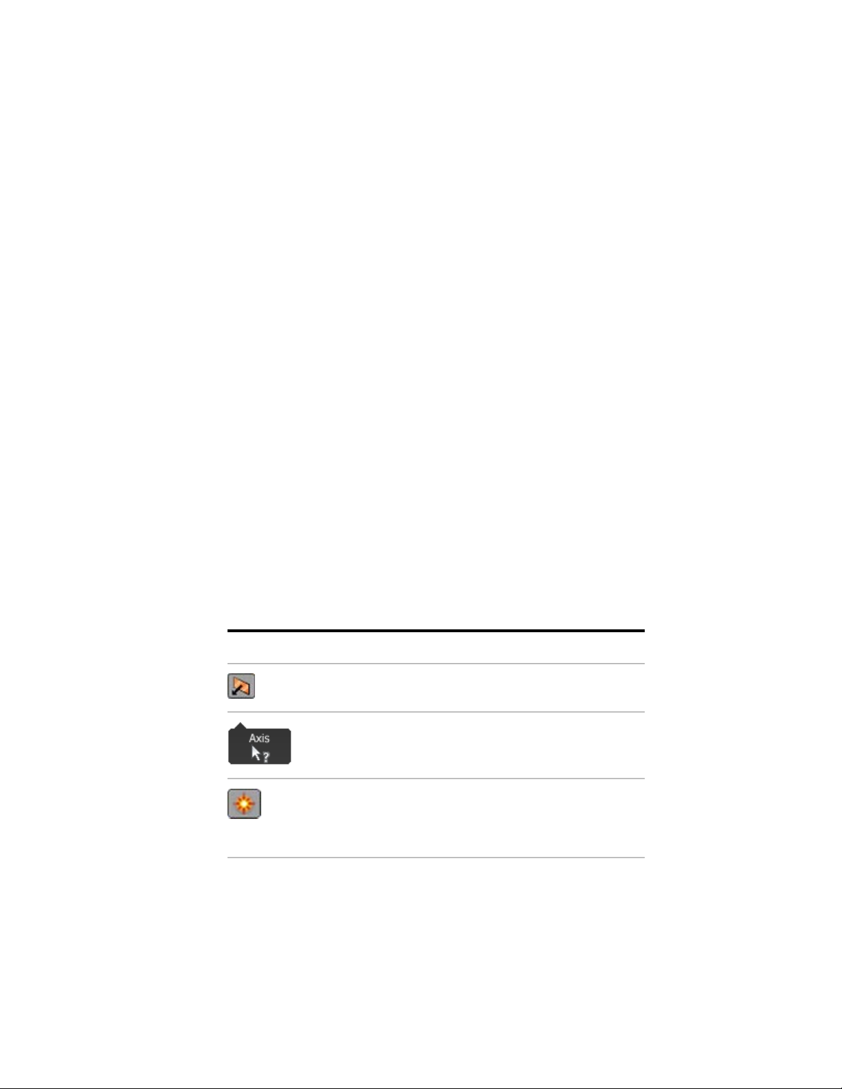
The most frequently used glyphs are in the following table:
Profile com-
mands
6 | Chapter 1 Autodesk Inventor Fusion TP2
DescriptionGlyph TitleGlyph Icon
Select a command option.Select Option
Go to the next input selection.Go to Next
This glyph is displayed when you select
(highlight) a closed sketch profile. Click
this glyph to select from a list of modeling
operations to perform on the profile.
Page 12
Manipulators
A Manipulator is a 3D command. It is usually an arrow, sphere, or ring that
appears while a command is active. It sets the distance, angle, or direction of
an operation, or for setting the location or size of a feature.
Drag the manipulator to complete (or preview) the operation. The value that
is set by dragging the manipulator can also be set in the ribbon or
heads-up-display (HUD). When you release the manipulator, the corresponding
value in the ribbon and HUD is updated.
An active, selected manipulator appears yellow. When two or more
manipulators are displayed, the active manipulator is yellow. The inactive
manipulator appears red or gray.
When there are two or more manipulators associated with a command, press
the Tab key to cycle from the current manipulator to the next one. This also
activates the heads-up display (HUD) field associated with the manipulator
(including those with multiple HUDs). You can measure on page 34 geometry
using the dropdown next to any HUD. You can enter simple arithmetic
expressions and mix units when you enter values into the HUD.
A manipulator that is used to set the location of a feature (such as the Hole
Center Manipulator) displays blue when the location is constrained (concentric
with another cylindrical feature or aligned with the midpoints of two edges,
and so on).
If you pause the cursor over a manipulator, a commandtip displays more
information about the manipulator.
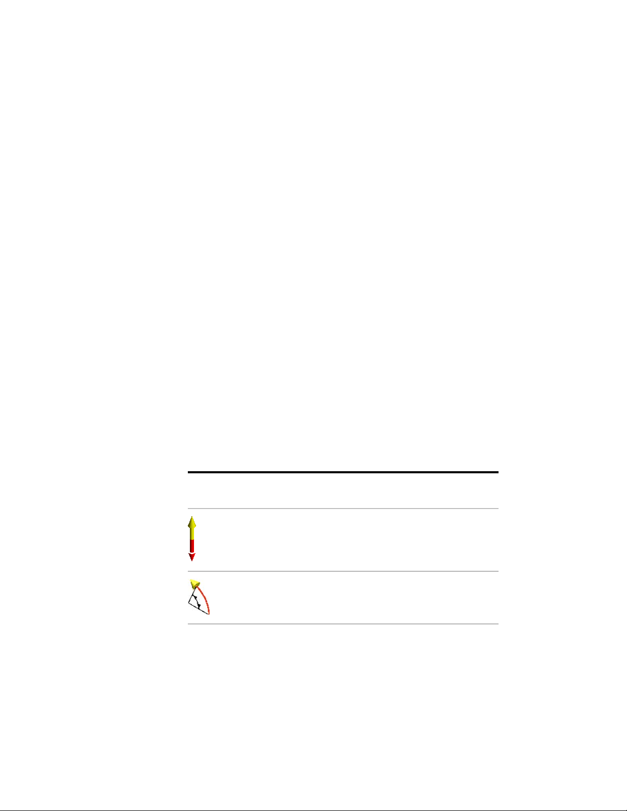
There are four basic manipulator types. The purpose of each varies by
command. Some common examples are listed in the following table:
Manipulator
Type
Linear Arrow
Radial Arrow
DescriptionManipulator
Used in the Extrude command to set
length and direction, and in the Hole
command to set the depth.
Used in the Revolve command to set the
rotation angle.
Glyphs and Manipulators | 7
Page 13

Ring
Used in the Hole command to set the hole
diameter as well as counterbore and
countersink diameters.
When using manipulators, you do not need to keep your cursor exactly on
the 3D arrow. You can drag anywhere over empty graphics space. Many
manipulators can also snap to other geometry on your model. While a
manipulator is active, you can pause your cursor over the design and prompts
appear over geometry that the manipulator can snap to.
Marking Menu
The Marking Menu is a spatially arranged, in-canvas menu used for executing
and completing (or canceling) commands. The contents of the marking menu
change based on the context in which it is invoked.
Sphere
Used in the Hole command to set the hole
center location, in the Extrude command
to set the taper angle, and in the Sweep
command to sweep the selected profile
along the path.
8 | Chapter 1 Autodesk Inventor Fusion TP2
Page 14
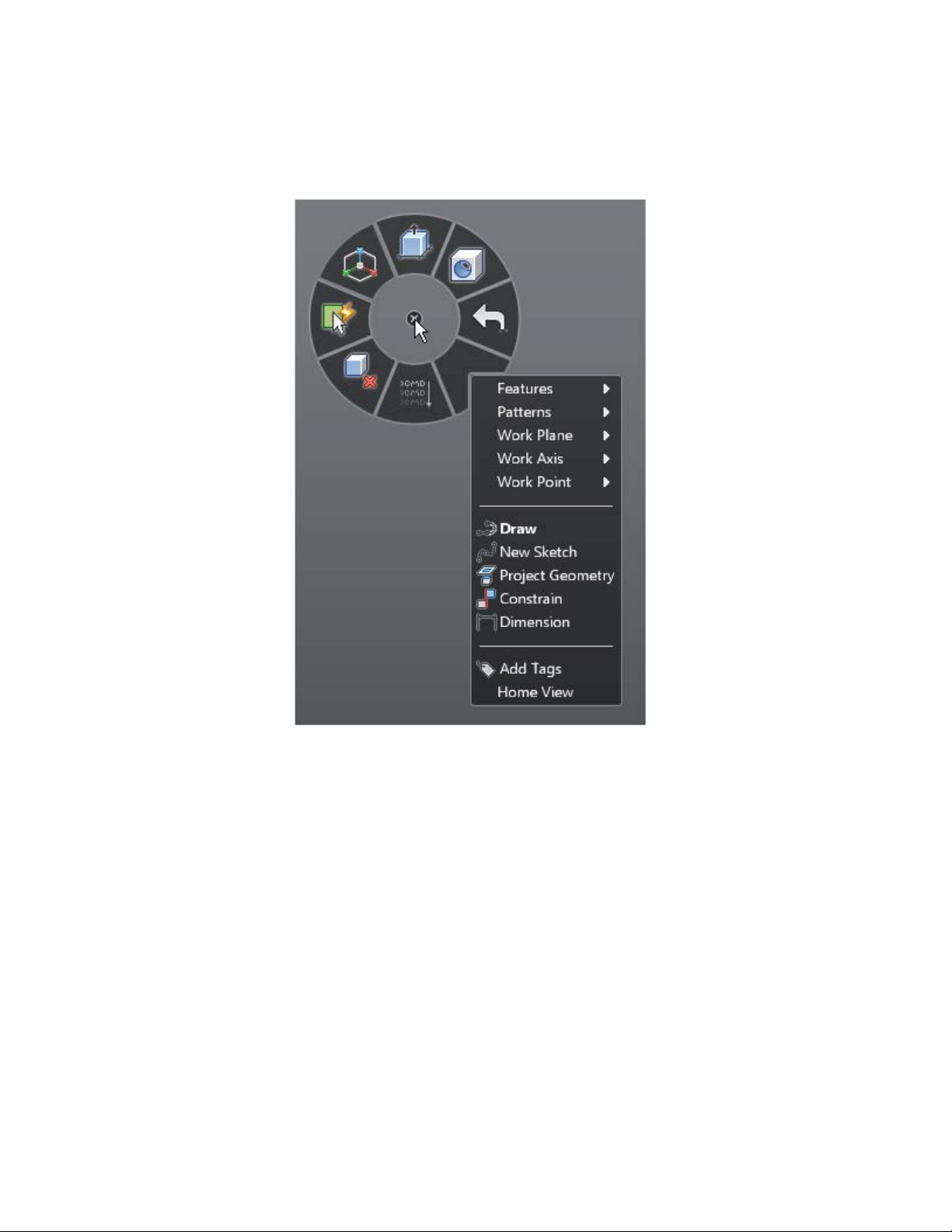
Marking Menu with Context Menu
The marking menu consists of eight wedges. Each wedge represents a
command/operation. These commands are the seven frequently used
commands and the eighth is a context menu which contains additional
commands.
Marking Menu | 9
Page 15

The default commands in the marking menu (context menu not shown) are:
1 Press Pull
2 Hole
3 Undo
4 Context Menu
5 Repeat Last Command
6 Delete
7 Select
8 Move
You can invoke and hide the marking menu through the following steps,
■ To start the marking menu, right-click or right mouse down
■ To close the marking menu, use the escape key, release the right mouse
button when no marking menu item is preselected, or click the left mouse
button when no item is selected.
You can hover (pause) the cursor over an item to see the commandtip for that
command.
10 | Chapter 1 Autodesk Inventor Fusion TP2
Page 16
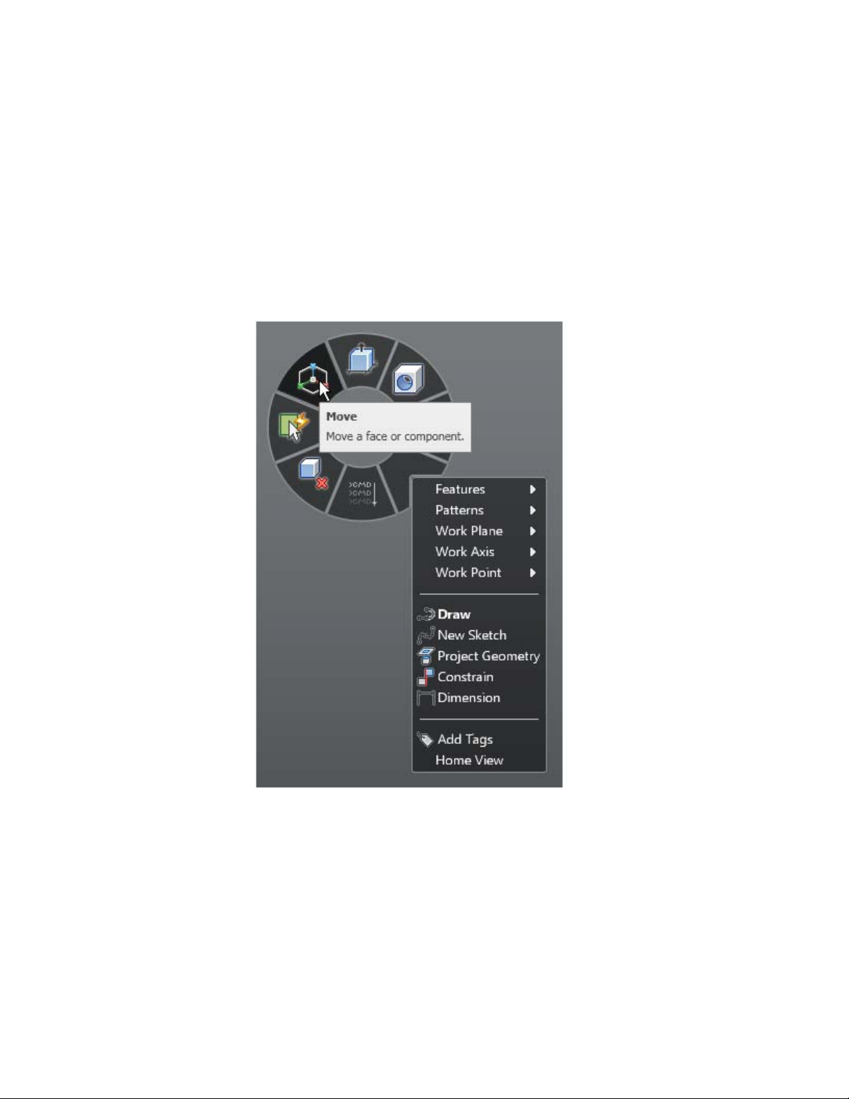
You can select an item from the marking menu through the following steps,
1 Invoke the marking menu (using either the right-click or holding the
right mouse down).
2 Drag the cursor to the appropriate item.
3 Once the cursor is over the appropriate item, release the cursor and click
the item.
The marking menu item for Move is highlighted and the commandtip for the
highlighted item is shown.
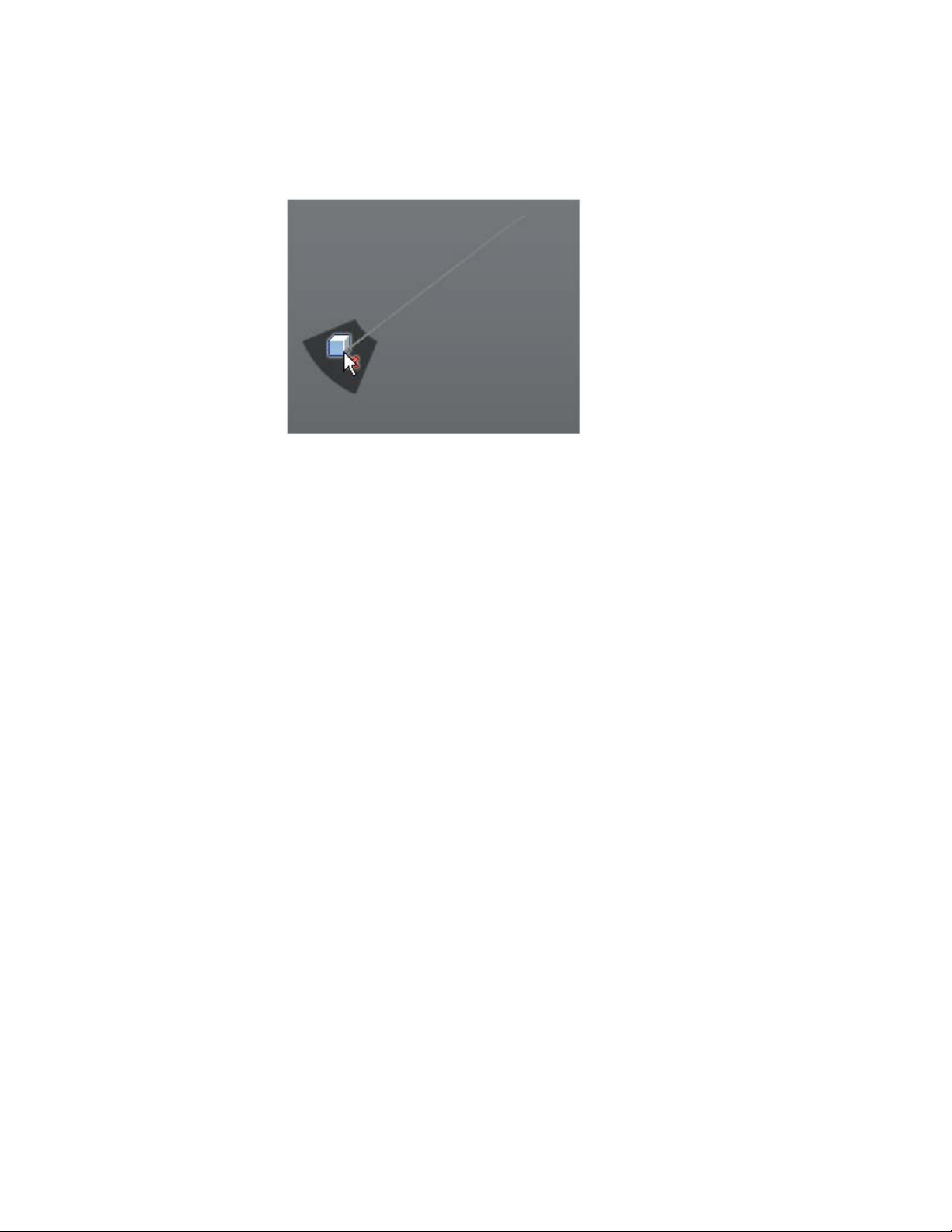
Gesture Behavior
Marking Menu | 11
Page 17

An alternative technique to execute a command in the marking menu involves
gesture behavior. This is useful when you are well conversant with the marking
menu layout and need a faster way to execute commands. Hence before using
gesture behavior, a little practice with the marking menu to develop some
muscle memory (familiarity) around the layout of the marking menu is helpful.
A gesture consists of starting the marking menu (right mouse down),
immediately dragging the cursor to the location of the intended marking
menu wedge and releasing the right mouse button before the entire marking
menu is displayed. If these operations are completed within 250 milliseconds,
only the selected wedge is briefly displayed to confirm that the operation was
performed.
Here are the steps for executing a gesture,
1 Start the marking menu (right mouse down).
2 Within 250 ms, drag the cursor in the direction of the wedge for the
appropriate operation.
3 Release the right mouse button.
During the drag gesture, a trail is visible in the canvas, showing the cursor
path. When you release the cursor, the selected wedge is displayed for a brief
time span. The command corresponding to this wedge then gets executed.
Visible train while dragging cursor in a gesture movement
12 | Chapter 1 Autodesk Inventor Fusion TP2
Page 18
Marking menu wedge appears when cursor is released
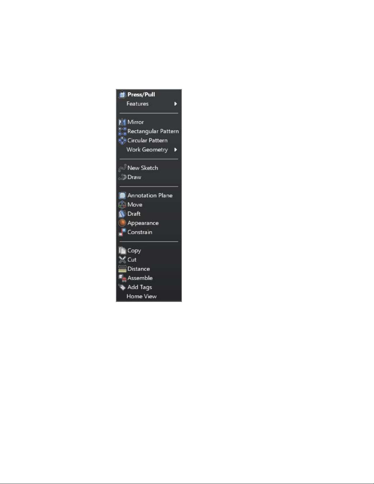
Context Menu
The marking menu displays a context menu in its 4th wedge. After you invoke
the marking menu, drag the cursor to the appropriate operation on the context
menu. When you release the cursor, the operation is selected.
The contents of the context menu change based on the current context
depending on,
■ Whether modeling mode/ sketch mode is on
■ Whether any entity is selected
Marking Menu | 13
Page 19
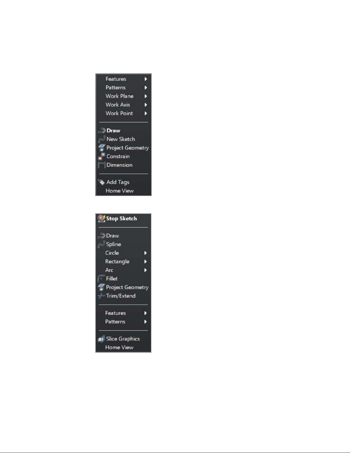
Context menu in modeling mode
14 | Chapter 1 Autodesk Inventor Fusion TP2
Page 20
Context menu in sketching mode
Context menu for Face selection
Marking Menu | 15
Page 21
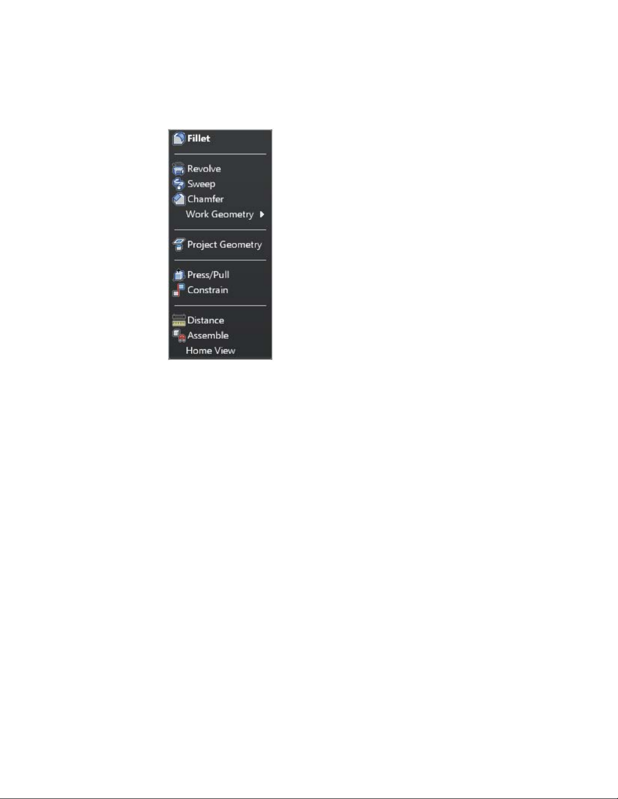
Context menu for edge selection
The context menu has a default menu item, which varies depending on the
context and selection. The default menu item appears in bold text. When you
select the 4th wedge of the marking menu in a gesture movement, the default
context menu item is invoked.
Primary Marking Menu Behavior when a Command is Active
When a command is active, certain items in the marking menu display a
different behavior depending on the context. The 3rd wedge item which
represents ‘Undo when executed outside a command, now assumes Cancel
behavior within a command.
16 | Chapter 1 Autodesk Inventor Fusion TP2
Page 22

Item no. 3 represents 'Cancel' when in mid-command
Item no 3. represents Undo outside a command
When a command is executing and you select a different command, the
current command is implicitly accepted if the input is valid. After this happens
the new command is started. This technique can be utilized for quickly
approving a command and ending it. The seventh wedge of the marking
menu, which represents a Finish action when a command is active, is an easy
way to do this. When you have provided the correct input for a command
and wish to OK it, bring up marking menu and click the Finish item to
implicitly OK the command and end it.
Marking Menu | 17
Page 23

Item no 7. represents 'Finish' which can be used to commit an active command
Selection commands
Mechanical designs often have many objects in the canvas which can make
selecting the appropriate object difficult.
The Select Other navigation commands in Inventor Fusion help you to select
obscured or difficult-to-select geometry. The different options for the Select
Other are accessible through a glyph which can be seen when you hover the
cursor over a face/edge. This face/ edge is termed as the root face/ edge.
Click the glyph to see the fly-out menu containing the following options:
Select Other while hovering over an edgeSelect Other while hovering over a face
1 By Depth
2 Neighbor
18 | Chapter 1 Autodesk Inventor Fusion TP2
Page 24
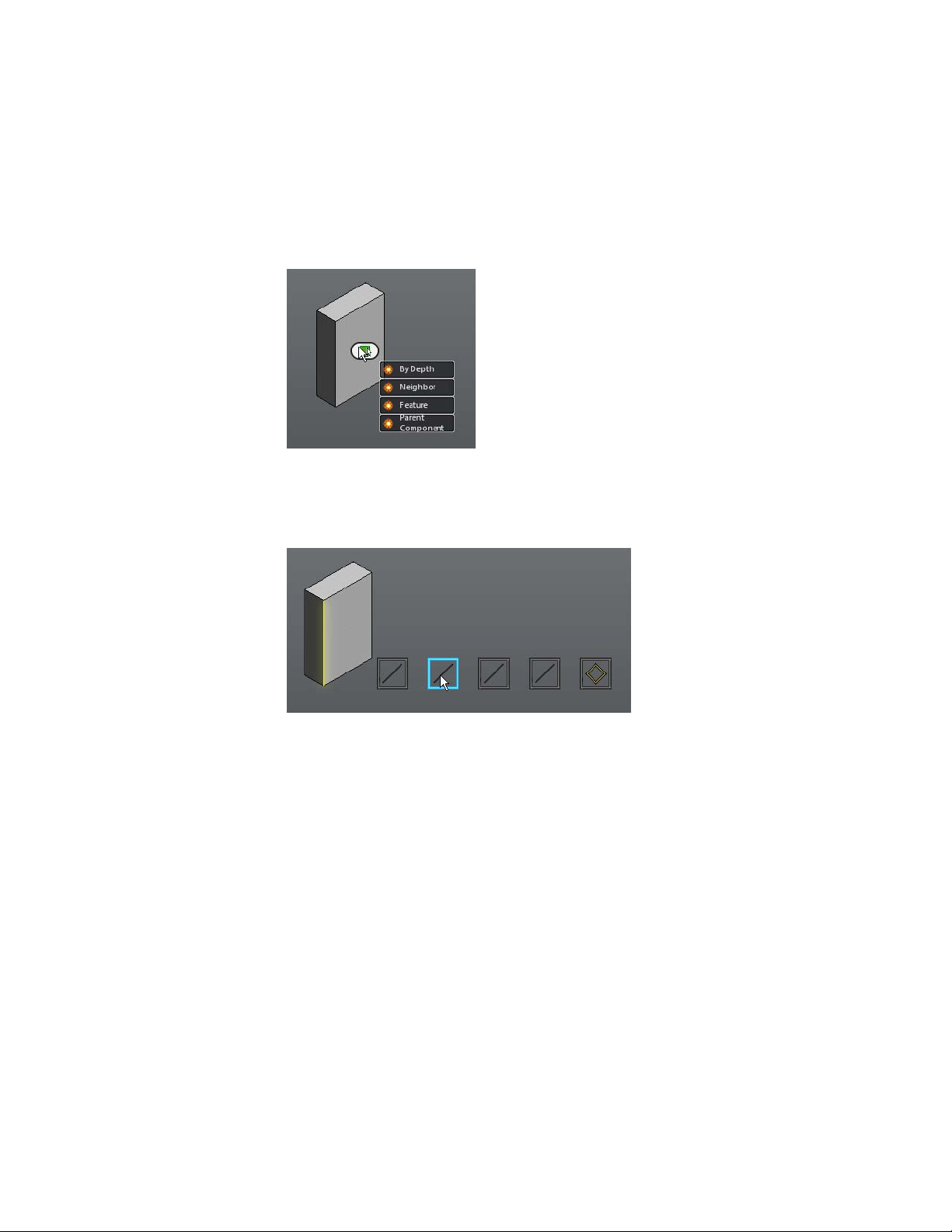
3 Feature
4 Parent Component
The Parent Component option directly selects the component which is the
parent for the face edge. When you select By Depth, Neighbor, or Feature, a
selection strip is displayed. The strip contains several frames each representing
a possible selection.
When you hover over a frame in the selection strip, the corresponding element
is highlighted in the model. When you click a frame in the selection strip,
the corresponding element is selected.
By Depth Selection
When you choose the ‘By Depth selection, eligible faces/ edges/ work planes/
work axes/ work points/ profiles that are partially or wholly obscured by the
selected element are listed on the selection strip.
Selection commands | 19
Page 25
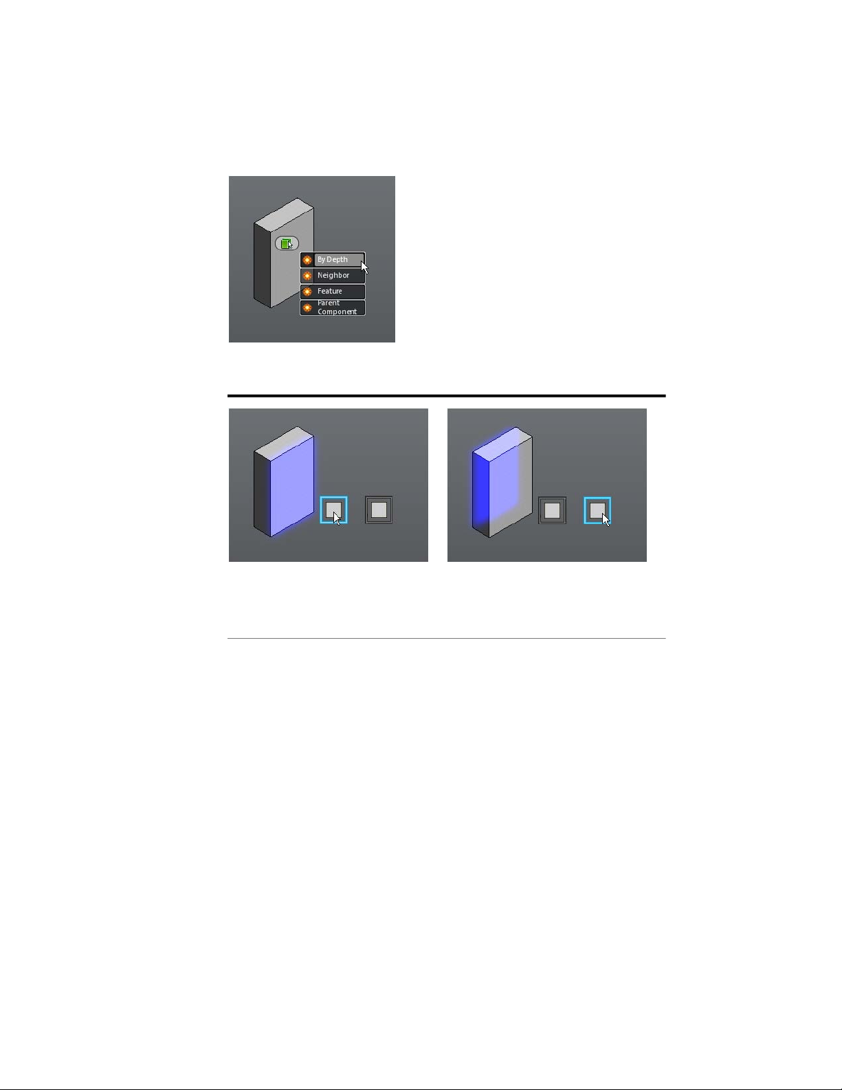
In the following example, eligible faces with different depth order are listed
in the selection strip.
When you highlight the first frame in the
Z Depth selection strip, the front most
overlapping face element is also highlighted.
Neighbor Selection
When you choose the Topological Neighbor selection, eligible elements that
are topologically connected to the root face/ edge are listed on the selection
strip. For the root face, list of connected edges and edge loops is displayed
while for a root edge a list of connected faces is displayed.
20 | Chapter 1 Autodesk Inventor Fusion TP2
The next frame selected in the strip causes
an eligible element with a different Z
Depth to be highlighted.
Page 26
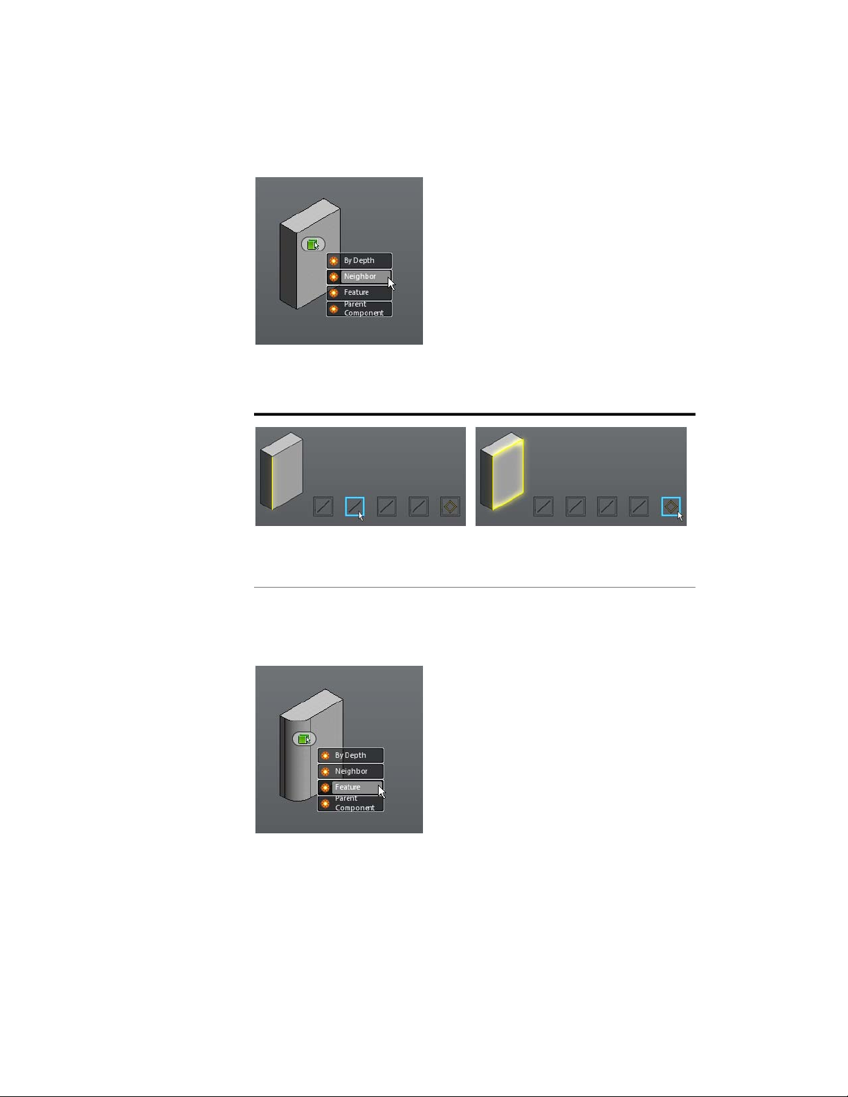
In the following example, the topological neighbors of a root face are listed
in the selection strip. The last item in the strip represents all the edge loops
connected with the root face.
When you highlight a frame in the selection strip, the corresponding edge element
is also highlighted.
The last frame causes all edge loops to be
highlighted.
Feature Selection
When you choose the Feature selection, eligible feature objects that are partially
or wholly obscured by the selected element are listed on the selection strip.
Selection commands | 21
Page 27
In the following example, both the extrusion and the fillet are eligible features.
The icons on the selection strip make it easy to identify the features by type.
The icon in the selected frame in the selection strip identifies the extrude feature.
The icon in the selected frame in the selection strip represents the fillet feature.
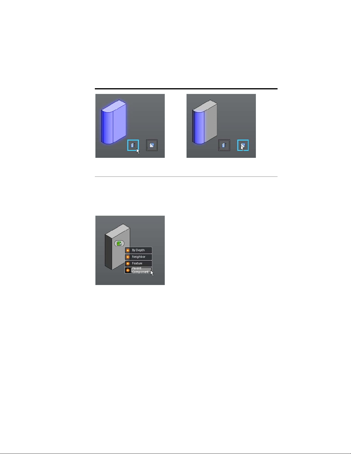
Parent Component Selection
When you choose the Parent Component Selection, the parent component
for the root face/edge gets selected. It is a short cut way to select the parent
component of an entity.
22 | Chapter 1 Autodesk Inventor Fusion TP2
Page 28
In the following example, the parent component of the root face gets selected.
The parent component option from the
fly-out was selected for the root face.
Consequently the parent component of
the root face is selected.
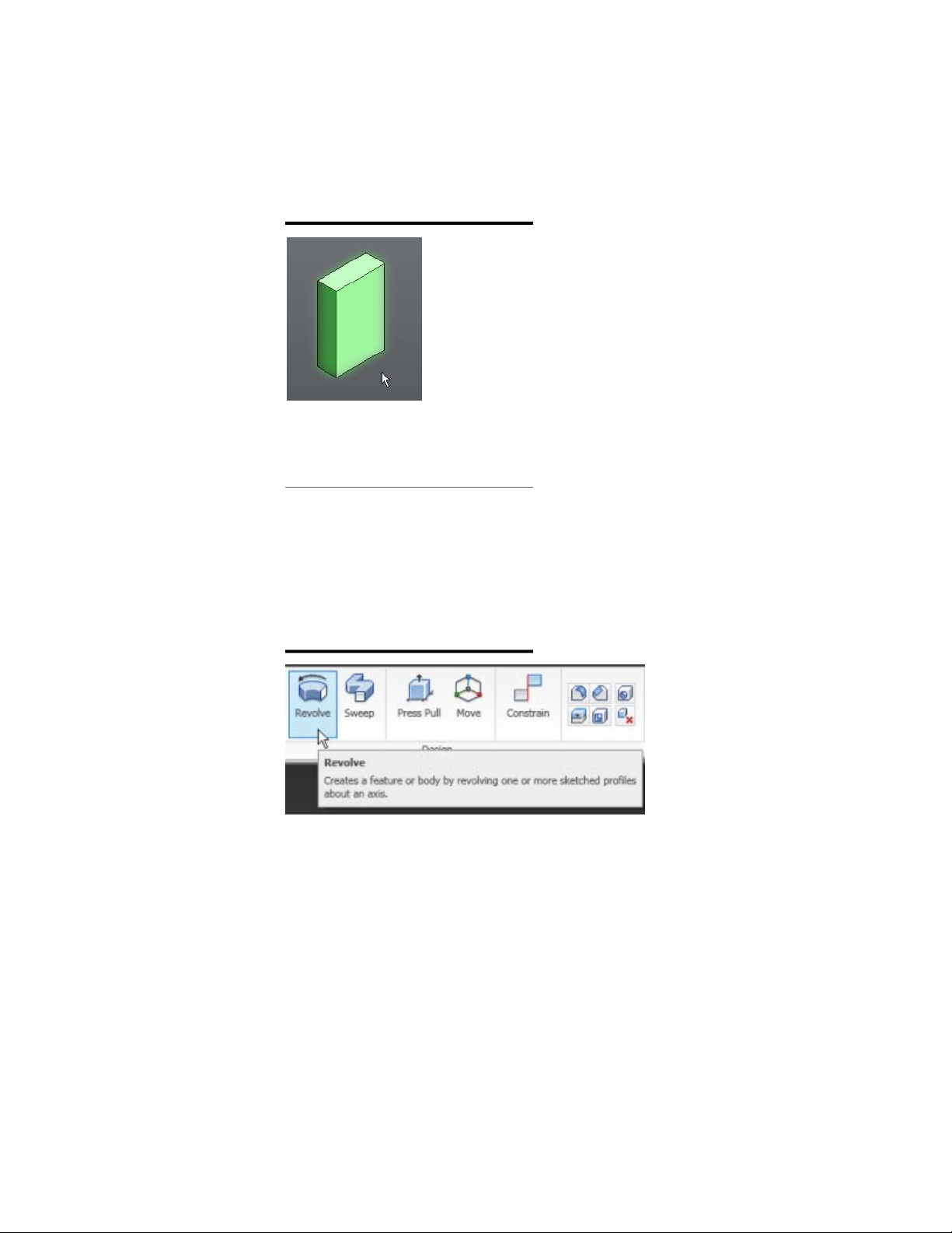
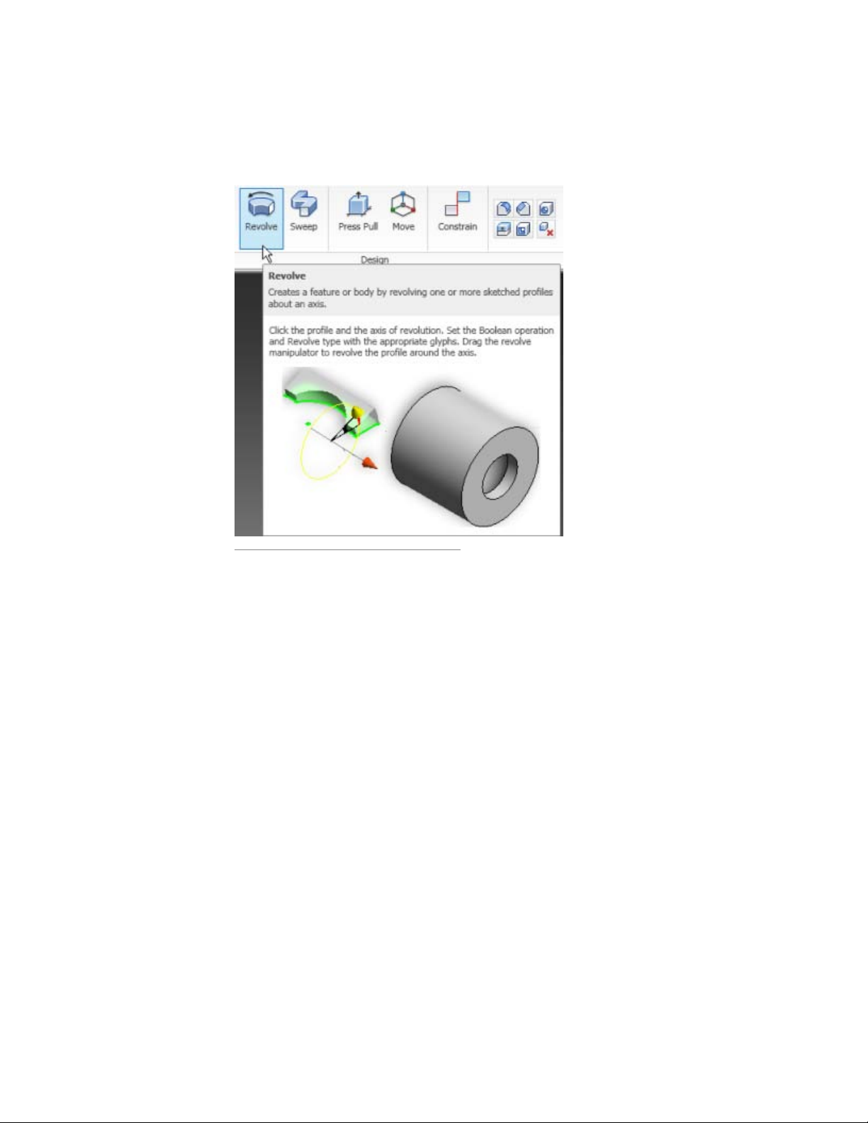
Enhanced tooltip
Many of the ribbon commands have enhanced (also referred to as progressive)
tooltip which display information for interaction with commands. Initially,
the name of the command and a short description of the command is
displayed. If you continue to pause the cursor, the commandtip expands to
display additional information.
Enhanced tooltip | 23
Page 29
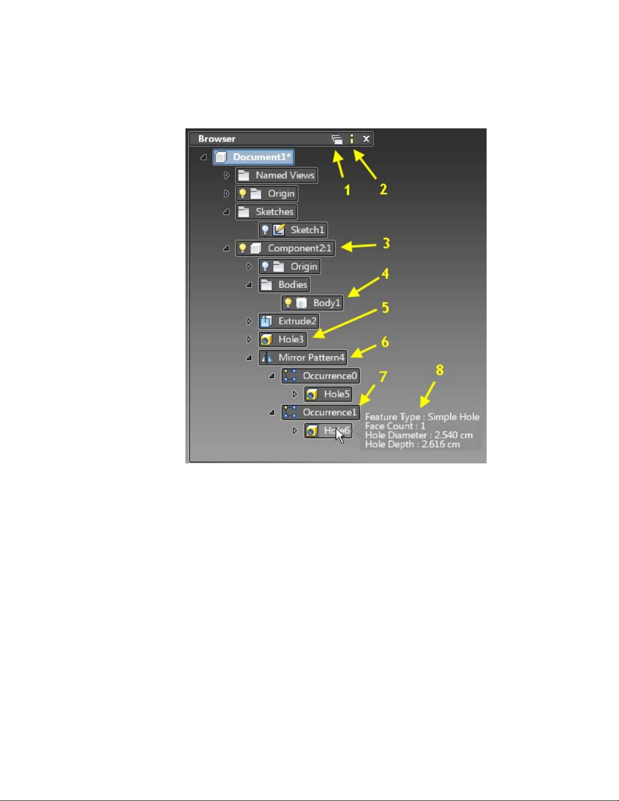
Browser and Copy/Paste
In Inventor Fusion, the browser presents an organized view of the data in your
design. Objects selected in the browser are selected in the graphics and
vice-versa. You can create new component instances in the browser. Bodies
can be dragged or copied and pasted from one component to another.
1 Toggle Favorites Folder
2 Toggle Information Panel
3 Child Component Node
4 Body Node
5 Feature Node
6 Pattern Node
7 Occurrence Node
8 Information Panel
24 | Chapter 1 Autodesk Inventor Fusion TP2
Page 30
The blue node in the browser denotes the active component in your design.
By double-clicking the component icon you can change the active component.
This is important when creating new sketches, work features and features. All
new objects that you create belong to the active component.
Information Panel
In Inventor Fusion, the model information is readily available. The browser
includes an information panel for each node, which you can switch on or off.
Pause the cursor over a component, body, feature, pattern, or occurrence to
view information about it.
Create New Component Instances
Right-click the top-level Document node and select New Component from
the context menu to create a child component under the document. Similarly,
Browser and Copy/Paste | 25
Page 31

right-click any component node and select New Component from the context
menu to create a child component under the selected component.
Additional Browser Functionality
Select Isolate Component to hide all but the selected component (UnIsolate
Component redisplays the hidden components).
Use the Favorites folder to group frequently referenced components, bodies,
features, and patterns.
Cut/Copy and Paste bodies from one component to another, or across
documents.
Delete components, bodies, and features.
Dissolve patterns.
Cut/Copy and Paste
Cut / Copy and Paste offer user-interface paradigms for transferring objects
from a source to a destination. Cut removes the object after pasting, whereas
copy keeps the source object intact after pasting. Inventor Fusion currently
supports the following objects for cut/copy and paste:
■ One or more pieces of sketch geometries
■ One or more body objects
■ One or more components (component instances)
■ Face sets
There is no undo/redo support for the cut or copy command. Paste and paste
new are supported for undo/redo.
Cut/Copy Interace
Objects can be selected from either the browser or using a graphical selection.
The cut and copy commands are available from various places as follows:
1 Browser: right-click a browser node
26 | Chapter 1 Autodesk Inventor Fusion TP2
Page 32

2 Marking Menu: right-click open space
3 Ribbon
4 Key strokes
This functionality has also been mapped to the key sequences Ctrl+X
and Ctrl+C.
Note: If the user uses cut, the actual cut operation does not happen until the
paste command is invoked. Every time a cut/copy command is used, the
previously cut/copied objects are cleared from the clipboard.
Paste Interface
Browser and Copy/Paste | 27
Page 33
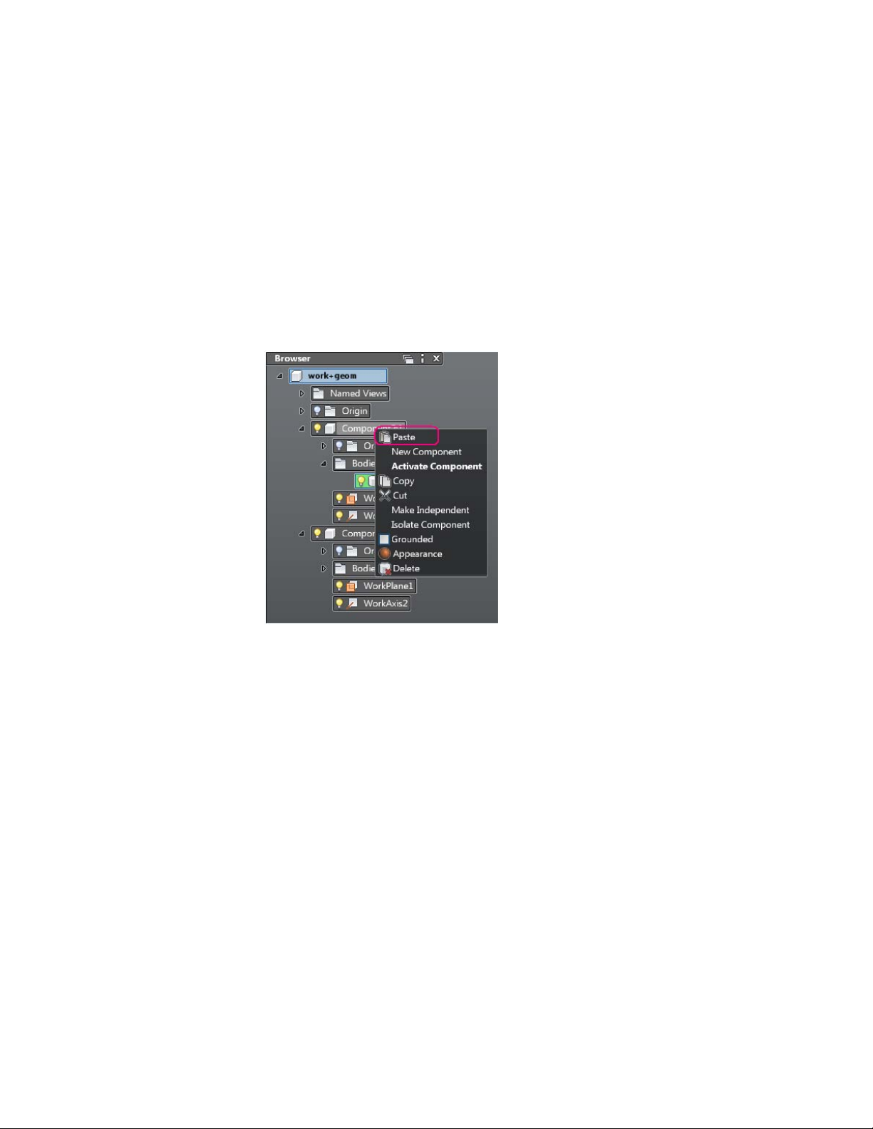
The paste command pastes previously cut/copied objects from the clipboard.
At the time of pasting a valid paste container is either deduced or needs to be
specified. Rules are as follows:
1 Browser Node
On a browser node that is a valid paste container. For example, a valid
paste container for a set of sketch geometries is a sketch node in the
browser. A component node is a valid paste container for a body or a
component instance as long as those objects are not already included
inside the component instance.
2 Graphical Selection
On a graphical selection that is a valid paste container. For example, a
face or a work plane is valid paste containers for sketch geometries.
28 | Chapter 1 Autodesk Inventor Fusion TP2
Page 34

3 Empty Space
When the paste command is invoked in empty space, the active sketch
or the active component is used as the paste container if that is valid.
Browser and Copy/Paste | 29
Page 35
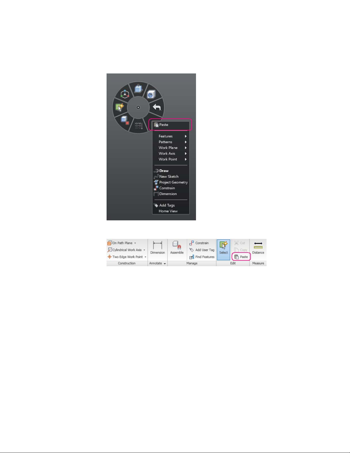
4 Ribbon
5 Key Strokes
This functionality has been mapped to the key sequence Ctrl+V.
Note: Objects can be pasted in a different document from the one they were
copied.
Implicit Paste Using Browser Drag and Drop
In addition, within a document, the user can drag and drop body objects and
component objects. These drag-and drop operations result in an implicit cut
and paste.
Paste New
30 | Chapter 1 Autodesk Inventor Fusion TP2
Page 36

When a component instance is cut/copied, it can be pasted as a “shallow
copy” or as a “deep copy”. In a shallow copy, a copy of the cut/copied
component instance is added to the new owner as a new component instance;
the structure under it is shared with other component instances. In a deep
copy the entire subassembly under the component instance is copied.
To distinguish between the two, a command called “Paste New” is available
when the cut/copied object is a component. Paste creates a shallow copy and
paste new creates a deep copy.
Note: When a component is copied and pasted across documents, only a deep
copy is possible, so only paste new is available.
Paste Behavior
When an object is pasted, there are two kinds of behavior depending on
whether the paste is explicit (invoked using the paste or paste new command)
or implicit (invoked by drag and drop in the browser).
Explicit Paste Behavior
When paste is done explicitly, the paste object is placed at the cursor and the
user is allowed to move it around on the screen and place it by clicking with
the left mouse button.
Explicit paste does not clear the clipboard, so it is possible to repeat the paste
(or paste new) command to repeatedly paste.
Browser and Copy/Paste | 31
Page 37
Implicit Paste Behavior
When paste is done implicitly, this is considered a restructure operation and
the pasted object changes its place in the hierarchy. Its location and orientation
in the world coordinate system remains unchanged. There is no user interaction
needed after the drag-drop.
Implicit paste clears the clipboard.
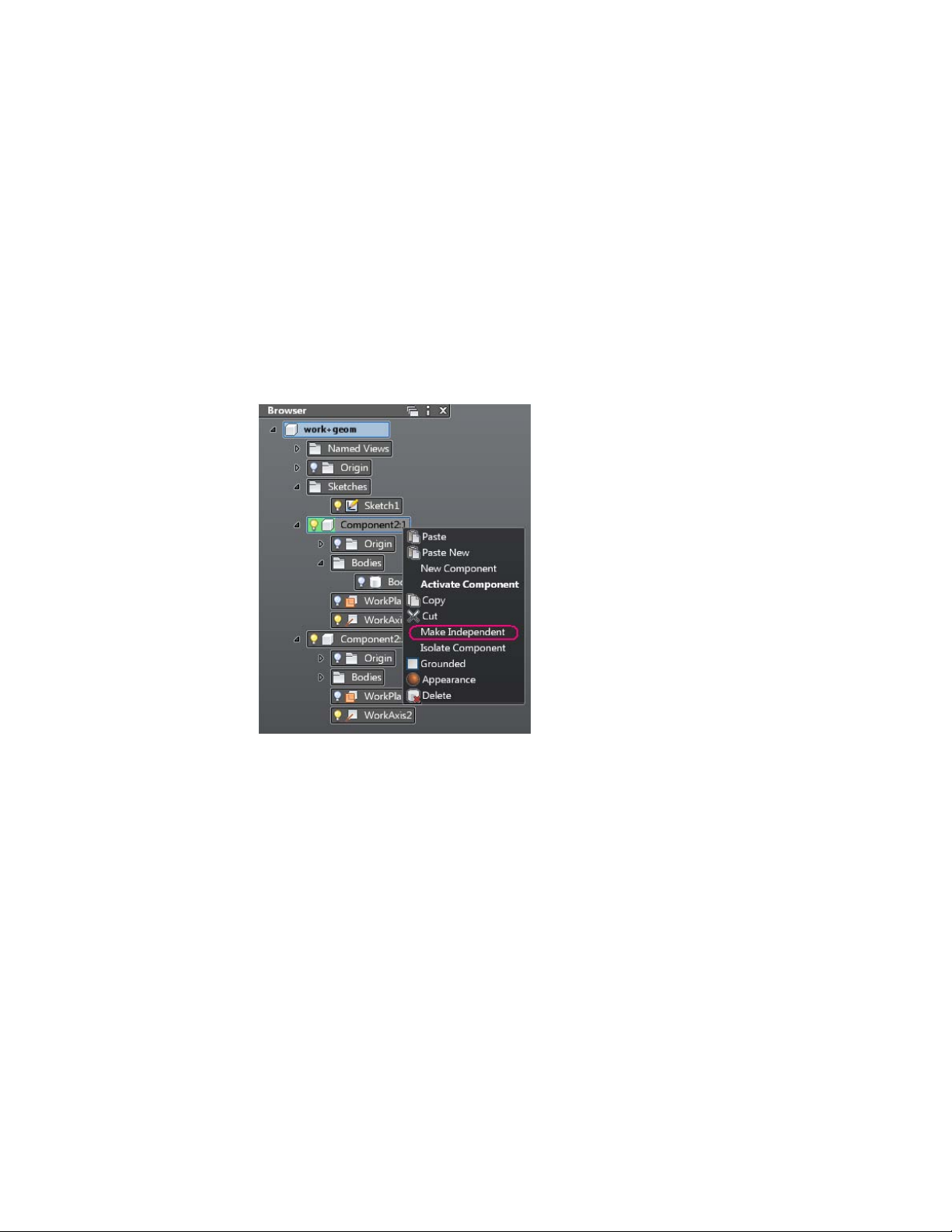
Make Independent
The “Make Independent” command operates on a component instance
selection either in the browser or a graphical selection.
This command makes the subassembly represented by the component instance
“independent”, for example, it is equivalent to a cut followed by a deep copy
of the component instance in the same parent container.
There is no placement interaction when using this command, as this is also
a “restructuring” operation.
Function Key Behavior
Some keys are reserved for specific purposes in Inventor Fusion. For example,
F1 accesses Help in all Microsoft Windows applications. In Inventor Fusion,
many of the F-keys (function keys) are reserved for global operations.
32 | Chapter 1 Autodesk Inventor Fusion TP2
Page 38

The following table contains all the reserved keyboard and mouse shortcuts
in Inventor Fusion:
BehaviorFunction Key
PanF2
ZoomF3
Zoom windowShift+F3
OrbitF4
Zoom allF6
Slice graphics (see note)F7
Triad
F10
Toggle shortcut keytips in Application
menu and Quick Access commandbar
PanMiddle mouse button
ZoomMouse wheel
OrbitShift+Middle Mouse button
Note: Slice Graphics operation requires the selection of a cutting plane. First
select a work plane or sketch profile, and then press the F7 key.
A Triad is a 3D in-canvas command for the movement and rotation of edges,
faces, features, bodies, and components. You can interactively position a face
or feature by dragging the triad in a planar move, axial move, or free
movement. The selected area of the triad controls the movement.
When the triad is displayed, select or drag a triad segment to indicate the
appropriate type of transform. In the heads-up display (HUD), you can enter
coordinates to move a face or feature precisely. When you drag the triad, the
X, Y, and Z coordinates dynamically update in the HUD.
Triad | 33
Page 39

■ Red is the X axis
■ Green is the Y axis
■ Blue is the Z axis
When you first activate the triad, its origin sphere is coincident with the
geometry to transform. Click a triad section or drag to indicate the appropriate
type of transform. As you select other parts of the triad, you can drag or enter
precise coordinates corresponding to your selection.
DescriptionTriad Part
Move the triad along the axis.Arrowheads
Rotate the triad around the axis.Arcs
Move the triad in the selected plane.Planes
Sphere
To reorient the triad relative to a different location without affecting the
geometry selection, press the F5 key and then click the new location for the
triad.
Measure
The Measure command provides two important functions:
■ Provide geometry information (distance, angle, area, and so on).
34 | Chapter 1 Autodesk Inventor Fusion TP2
Allows unrestricted movement in the view
plane.
Page 40

■ Populate input boxes with measurement.
Access the measure command in the ribbon or in the fly out of any input box.
Selection Support
You can select objects in the browser or in the graphics window when using
measure. You can also use filters to control which geometry types are eligible
for selection.
Measure Dialog Box
Measure | 35
Page 41

The measure dialog box is displayed when the command is started and persists
until the command is terminated. The dialog box displays geometry
information dependent on the selected entities.
click a row in the measure dialog box to copy that value to the clipboard. Use
Ctrl + V to paste the value.
Click and drag the dialog box to reposition it.
Sample Workflow
1 Select a face to extrude.
2 Start the measure command from the value input fly out and select the
objects to measure.
3 To set the length of the extrusion equal to the length of the selected edge
(2), click the Curve 2 Length row in the measure dialog box. The value
is copied to the input box and as well as the clipboard.
4 After clicking the value, the measure dialog box is dismissed and the
model is updated accordingly.
Menu and Command Access
Execute commands in Inventor Fusion in the following ways:
■ Click the command button on the ribbon.
■ Select the command from the marking menu.
■ Select the command name in the context menu.
36 | Chapter 1 Autodesk Inventor Fusion TP2
Page 42

Most commands are available in both the ribbon and the context menu. A
subset of frequently used commands appears in the marking menu.
For more information see Marking Menu on page 8.
Note: Right-click to display the marking menu and context menu.
Other commands in the Application Window
The application window displays commands such as the application button,
the Quick Access commandbar, and the status bars.
Other commands in the Application Window | 37
Page 43

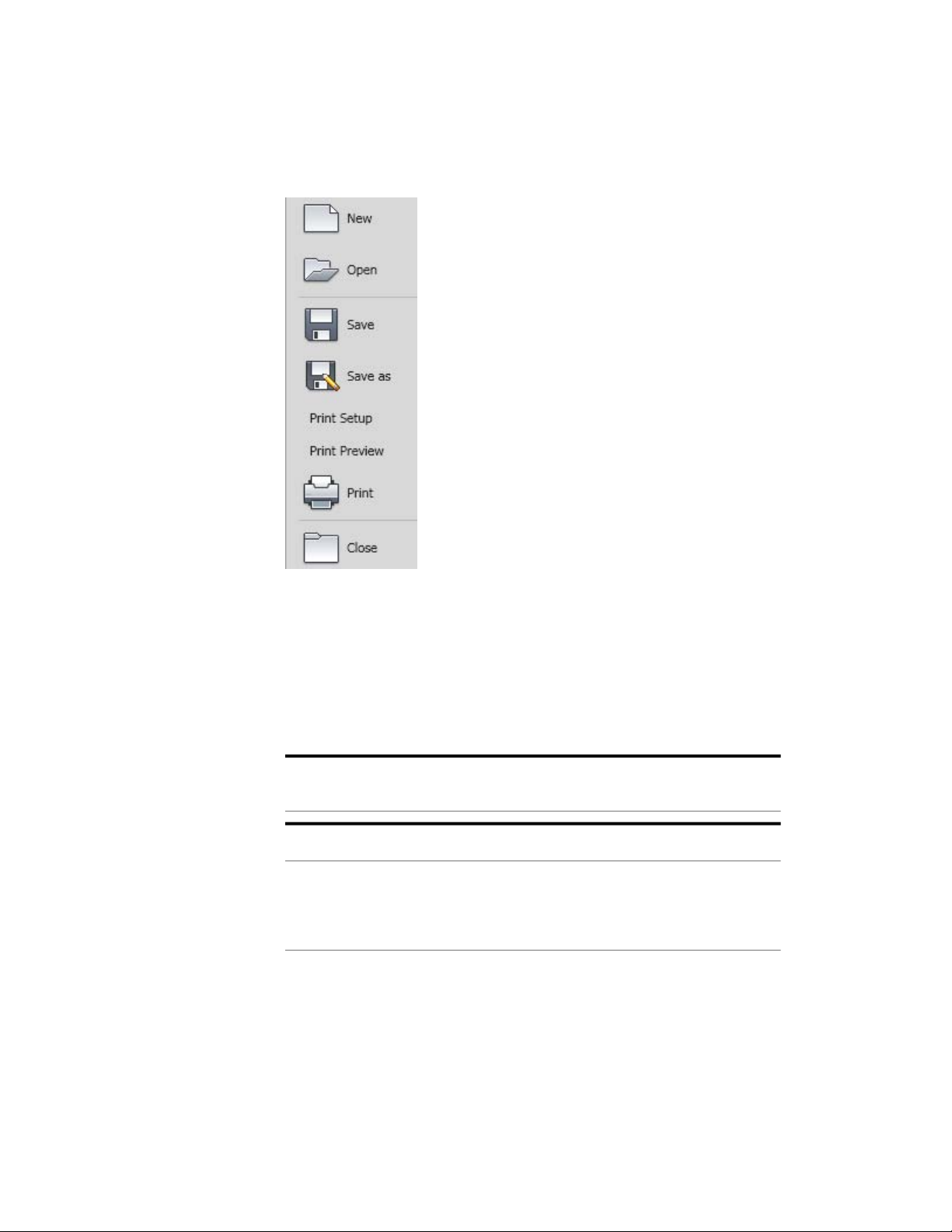
Application Menu
Click the application button to access commands to create, open, and export
a file.
Access Common commands
Access common commands to start or export a file from the Application
Menu.
Click the application button to:
■ Create a file.
■ Open an existing file.
■ Save a file.
■ Save a file as another name.
■ Print a file.
■ Close the application.
38 | Chapter 1 Autodesk Inventor Fusion TP2
Page 44
Quick Reference
This section contains descriptions of file access and print dialog boxes.
File Open
File Open
Access:
File list
Opens when you perform operations requiring selection of a file.
Shows path of the active directory.Look in
The main window shows a list of the subfolders and files in the selected path.
Double-click a subfolder to show the files
it contains.
Other commands in the Application Window | 39
Page 45
File name
Specifies the file to open, enter a file name,
or select a file from the listed files.
New File
Files of type
Cancel
Filters file list to include only files of a specific type. Click the arrow to show list, and
then highlight to select a file type.
Open the selected file.Open
Cancels the file open operation and closes
the dialog box.
New File
Creates a file.
Print
Prints or plots all or any portion of a model.
Access:
Click Print.
Sets the options for printing or plotting all or a portion of the active model.
Name
Properties
Print Range
40 | Chapter 1 Autodesk Inventor Fusion TP2
Specifies the printer or plotter. To change
the printer or plotter, click the arrow and
select from the list.
Opens the Print Setup dialog box used to
set the paper size and orientation.
Sets the page range to print. For a model,
only the portion of the model that is displayed in the graphics window is printed
(All is the only option available).
Page 46
Number of Copies
You can print or plot all or any portion of a model.
To print a model
You can print or plot all or any portion of the active model.
1 Set up the view of the model. Only the portion of the model that is
2 Click Print.
3 In the Print dialog box, enter the number of copies. If necessary, click
4 Click OK to print.
Save, Save As
Sets the number of copies to print. Enter
the number of copies, or use the up or
down arrow to select the number of copies.
displayed in the graphics window prints.
Properties to open the Print Setup dialog box, and then change the paper
size and orientation.
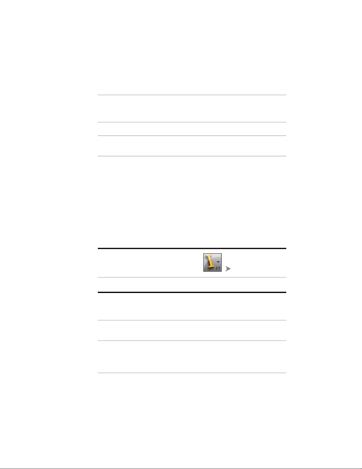
Save, Save As
Saves a file with a specified name and file type.
In the Application Menu, select:Access:
Save Save
The Save command saves the active document contents to the file specified in the
window title, and the file remains open.
Save As Save As
Save As saves the active document contents to the file specified in the Save As
dialog box. The original document is
closed and the newly saved file is opened.
Other commands in the Application Window | 41
Page 47

The contents of the original file are un-
changed.
Save in
Locations
File name
File of type
Save
Cancel
Available file types:
DWG
SAT
Shows path of the active directory and
specifies destination of the saved file.
Specifies the name of the file to save. If the
file was saved, the file name is shown.
Filters file list to include only files of a specific type. Click the arrow to show list, and
then highlight to select a file type. The extension is added to the file name.
Saves highlighted file (with file name and
type specified by one of the methods explained previously).
Cancels the save operation and closes the
dialog box.
Geometry objects stored in ASCII files.
(versions 4.0 - 7.0).
STEP
42 | Chapter 1 Autodesk Inventor Fusion TP2
An international format developed to
overcome some of the limitations of current data conversion standards. Files created in other CAD systems can be converted to STEP format and imported into Inventor Fusion. (versions AP214 and
AP203E2)
Page 48

Recent Documents
View the most recently used files with the Recent Documents list.
Files display in the Recent Documents list with the most recently used file at
the top by default.
Pinned Files
You can keep a file listed, regardless of files that you save later, using the push
pin button to the right. The file is displayed at the bottom of the list until you
turn off the push pin button.
Sort and Group Options
Use the By Ordered list drop-down menu at the top of the Recent Documents
list to sort or group files by:
■ File name
■ File size
■ File type
Procedure
■ Date the files were last modified.
Click Open Documents to view open documents.
Other commands in the Application Window | 43
Page 49
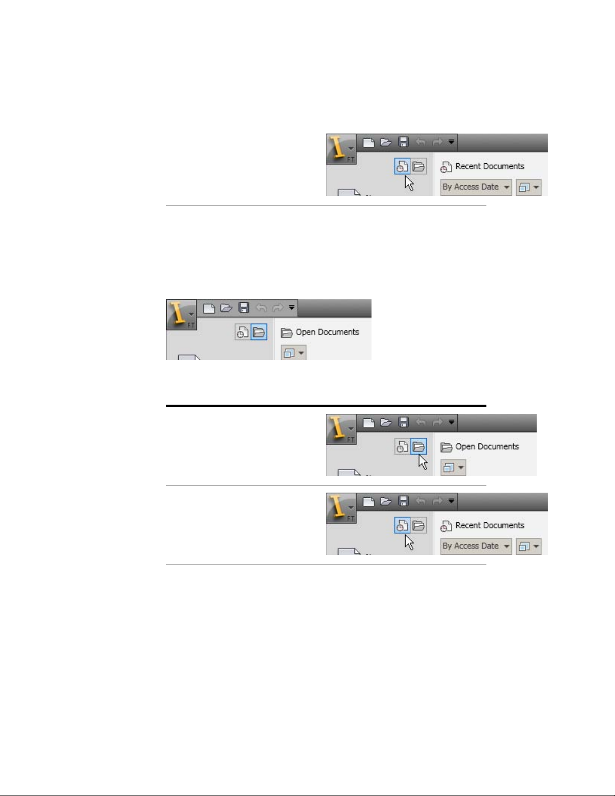
Click Recent Documents to view recent
documents.
Currently Open Documents
View only files that are currently open with the Open Documents list.
Files display in the Open Documents list with the most recently opened file
at the top. To make a file current, click the file in the list.
Procedure
Click Open Documents to view open documents.
Click Recent Documents to view recent
documents.
Preview Documents
View file information in the Recent Documents and Open Documents lists.
44 | Chapter 1 Autodesk Inventor Fusion TP2
Page 50
When you pause the cursor over a file in either of the lists, the following
information is displayed:
■ Path where the file is stored
■ Date the file was last modified
■ Version of the product used to create the file
■ Name of the person who last saved the file
■ Name of the person who is currently editing the file
Quick Access commandbar
Display frequently used commands with the Quick Access commandbar.
View Undo and Redo History
The Quick Access commandbar displays options to undo and redo changes
to your file.
Add Commands and Controls
Add unlimited commands to the Quick Access commandbar. commands that
extend past the maximum length of the commandbar are displayed in a
drop-down menu.
Procedure
To add a ribbon command to the Quick Access commandbar, right-click the
command on the ribbon, and click Add to Quick Access commandbar.
Commands are added to the right of the default commands on the Quick
Access commandbar.
Move the Quick Access commandbar
Place the Quick Access commandbar either above or below the ribbon using
the Customization button.
To add and remove commands to the Quick Access commandbar
1 On the Quick Access commandbar, click the drop-down arrow.
Other commands in the Application Window | 45
Page 51
Status Bar
2 On the Customize menu, click the command name to display on the
Quick Access commandbar.A check mark next to a command name
indicates it is displayed on the Quick Access commandbar.
To add commands to the Customize Quick Access commandbar menu
➤ On the ribbon, right-click the command add, and select Add to the Quick
Access commandbar.
To move the Quick Access commandbar menu above or below the ribbon
1 On Quick Access commandbar, click the drop-down arrow.
2 On the Customize menu, click Show Above the Ribbon to display the
Quick Access commandbar above the ribbon. Or, click Show Below the
Ribbon to display the Quick Access commandbar below the ribbon.A
check mark next to a command name indicates it is displayed on the
Quick Access commandbar.
The Status bar displays across the bottom of active window. The status bar
provides the following information:
■ When you are in a command that requires you to perform an action to
continue, a message displays on the far bottom left. It indicates the next
step to proceed with the active command.
Keytips
Use the keyboard to access the Application Menu, Quick Access commandbar,
and ribbon.
Press Alt or F10 to display shortcut keys for common commands in the
application window. Use keytips to perform tasks without using your mouse.
When you select a keytip, more keytips are displayed for that command.
Keytips appear as underlined characters to indicate which key or combination
of keys on the keyboard to press to activate a command.
46 | Chapter 1 Autodesk Inventor Fusion TP2
Page 52
Use keytips to navigate in the Application Menu and in the ribbon using only
the keyboard. Use the keyboard arrows to navigate to commands on the ribbon
and Application Menu
Navigation commands
Navigation commands change the orientation and view of your model.
The display of a model can be adjusted by increasing or decreasing the
magnification at which objects are displayed or rotating the view of the model.
Use the View Cube, SteeringWheels, and commands in the Navigation panel
to change the view of your model. You can create a view that defines an area
of a model as the Home view and use preset views to restore known viewpoints
of a model with the View Cube.
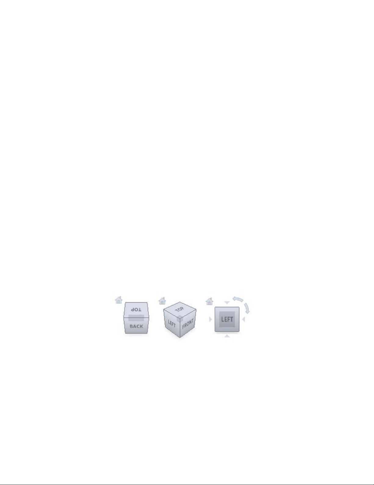
View Cube
Overview of the ViewCube
The ViewCube command is a persistent interface that you use to switch
between standard and isometric views of your model. When you display the
ViewCube command, it is shown in one of the corners of the window over
the model in an inactive state. While the ViewCube command is inactive, it
provides visual feedback about the current viewpoint of the model as view
changes occur. When the cursor is positioned over the ViewCube command,
it becomes active; you can switch to one of the available preset views, roll the
current view, or change to the Home view of the model.
Control the Appearance of ViewCube
The ViewCube command is displayed in one of two states: inactive and active.
When the ViewCube command is inactive, it appears partially transparent by
default so that it does not obscure the view of the model. When active, it is
Other commands in the Application Window | 47
Page 53

opaque and may obscure the view of the objects in the current view of the
model.
In addition to controlling the inactive opacity level of the ViewCube command,
you can also control the following properties for the ViewCube command:
■ Size
■ Position
■ Default orientation
■ Compass display
Using the Compass
The compass is displayed below the ViewCube command and indicates which
direction North is defined for the model. You can click a cardinal direction
letter on the compass to rotate the model, or you can click and drag one of
the cardinal direction letters or the compass ring to interactively rotate the
model around the center of the view.
Reorient the View of a Model with the ViewCube
ViewCube is used to reorient the current view of a model. You can reorient
the view of a model with the ViewCube by clicking predefined areas to set a
preset view current. Click and drag to change the view angle of the model,
and define and restore the Home view.
48 | Chapter 1 Autodesk Inventor Fusion TP2
Page 54

ViewCube Menu
Use the ViewCube menu to restore and define the Home view of a model,
switch between view projection modes, and change the interactive behavior
and appearance of the ViewCube.
The ViewCube menu has the following options:
■ Go Home
restores the Home view saved with the model.
■ Orthographic
switches the current view to orthographic projection.
■ Perspective
switches the current view to perspective projection.
■ Perspective with Ortho Faces
switches the current view to perspective projection unless the current view
aligns with a face view defined on the ViewCube.
■ Lock to Selection
uses the selected objects to define the center of the view when a view
orientation change occurs with the ViewCube.Note: If you click Home on
the ViewCube, the view returns to the Home view even if Lock to Current
Selection is selected.
■ Set Current View as Home
defines the Home view of the model based on the current view.
■ Restore Default Home
resets the Home view of the model to its default orientation.
■ Set Current View as Front
defines the Front view of the model based on the current view.
■ Reset Front
resets the Front view of the model to its default orientation.
■ Properties
displays the dialog box so you can adjust the appearance and behavior of
the ViewCube.
■ Help Topics
Opens the Help system and displays the topic for the ViewCube.
Other commands in the Application Window | 49
Page 55

Procedure
To display the ViewCube menu, do the following:
■ Right-click the compass, Home icon, or the main area of the ViewCube.
■ Click the context menu button located near the ViewCube.
SteeringWheels
SteeringWheels are tracking menus (that follow your cursor) from which you
can access different 2D and 3D navigation commands from a single command.
Navigation commands
Each wheel is divided into different wedges. Each wedge contains a navigation
command that you can be uses to reorient the current view of a model. The
navigation commands that are available depend on the active wheel.
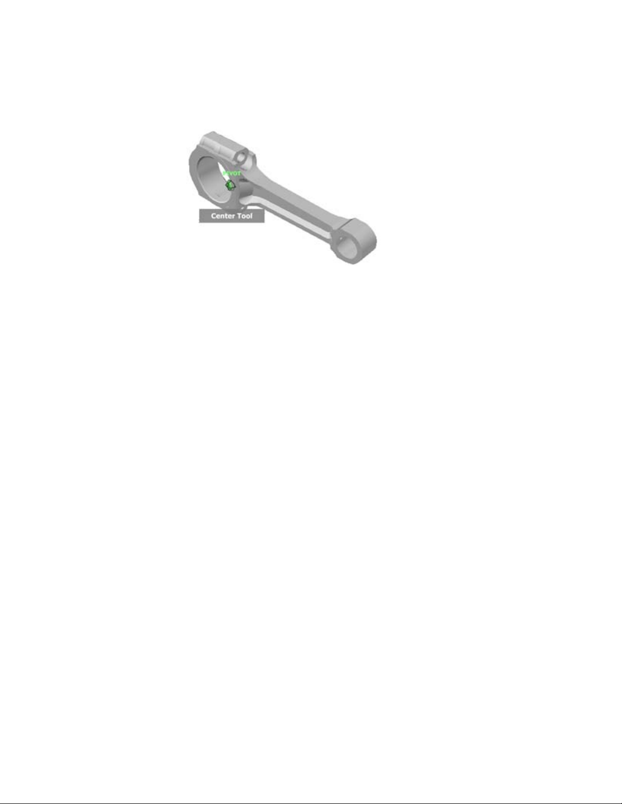
Center command
With the Center command, you can define the center of the current view of
a model. To define the center, drag the cursor over the model. A sphere is
displayed in addition to the cursor. The sphere indicates that the point below
the cursor in the model is the center of the current view. When you release
the mouse button, the model is centered on the sphere.
Note: If a center point on a model cannot be identified, then an icon indicating
that the operation cannot be performed. A circle with a diagonal line is
displayed instead of the sphere.
50 | Chapter 1 Autodesk Inventor Fusion TP2
Page 56
The point defined by the Center command provides a focal point for the Zoom
command and a pivot point for the Orbit command.
Note: To zoom from the Full Navigation wheels from your defined center
point, hold down the Ctrl key before zooming.
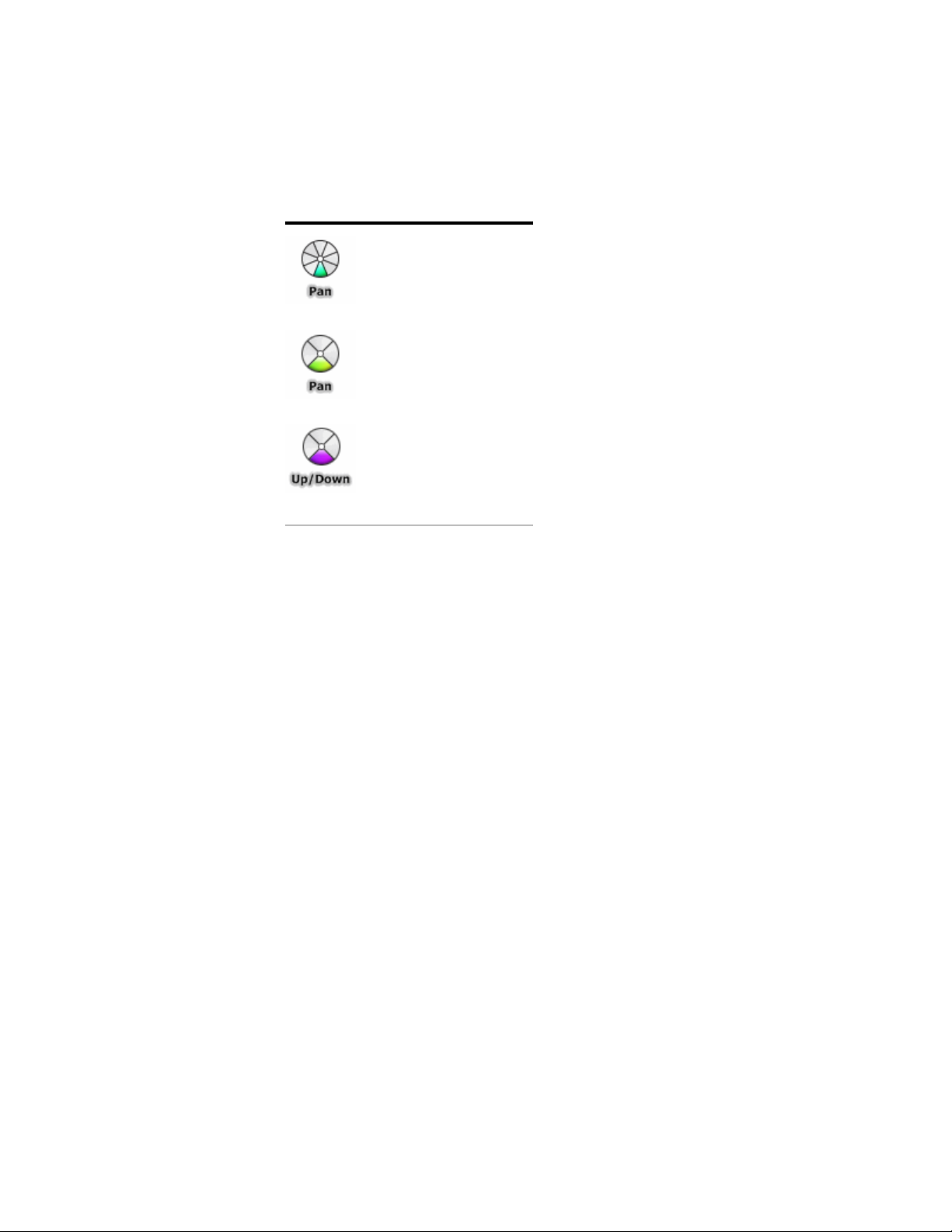
Up/Down command
Unlike the Pan command, you use the UP/Down command to adjust the
height of the current viewpoint along the Z axis of the model. To adjust the
vertical elevation of the current view, you drag up or down. As you drag, the
current elevation and the allowed range of motion is displayed on a graphical
element called the Vertical Distance indicator.
The Vertical Distance indicator has two marks that show the highest (Top)
and lowest (Bottom) elevation possible for the view. While changing the
elevation with the Vertical Distance indicator, the current elevation is shown
by the bright orange indicator. The previous elevation is shown by the dim
orange indicator.
Other commands in the Application Window | 51
Page 57

Procedure
1 Display one of the Full Navigation wheels or the Tour Building wheels.
2 Click and hold down the Up/Down wedge.The Vertical Distance indicator
is displayed.
3 Drag up or down to change the elevation of the view.
4 Release the button on your pointing device to return to the wheel.
Forward command
Use the Forward command to change the magnification of the model by
increasing or decreasing the distance between the current point of view and
the pivot point. The distance that you can move forward or backward is limited
by the position of the pivot point.
Note: In orthographic views, the Forward command is limited to the distance
between the current position and the pivot point. In perspective views, it is
not limited, allowing you to move the cursor through the pivot point.
52 | Chapter 1 Autodesk Inventor Fusion TP2
Page 58

To adjust the distance between the current point of view and the pivot point
you use the Drag Distance indicator. The Drag Distance indicator has two
marks on it that show the start and destination distances from the current
point of view. The current traveled distance is shown by the orange position
indicator. Slide the indicator forward or backwards to decrease or increase the
distance towards the pivot point.
Procedure
1 Display the big Tour Building wheel.
2 Click and hold down the Forward wedge within the scope of the model.
The Drag Distance indicator is displayed.
Note: If you click the Forward wedge once, the model moves forward
50% of the distance between the current location and the pivot point.
3 Drag the cursor up or down to change the distance from which you view
the model.
4 Release the button on your pointing device to return to the wheel.
Look command
With the Look command, you can rotate the current view vertically and
horizontally. When rotating the view, your line of sight rotates about the
current eye position, like turning your head. The Look command can be
compared to you standing in a fixed location, and looking up or down while
turning your head left or right.
Other commands in the Application Window | 53
Page 59

When using the Look command, adjust the view of the model by dragging
the cursor. As you drag, the cursor changes to the Look cursor and the model
rotates around the location of the current view.
Walking through a Model
When using the Look command from the big Full Navigation wheel, you can
walk through a model by using the arrow keys on the keyboard. Use the
Properties dialog box for the SteeringWheels to adjust the walk command.
Invert Vertical Axis
When you drag the cursor upward, the target point of the view lowers; dragging
the cursor downward raises the target point of the view. Use the properties
dialog box for the SteeringWheels to invert the vertical axis for the Look
command.
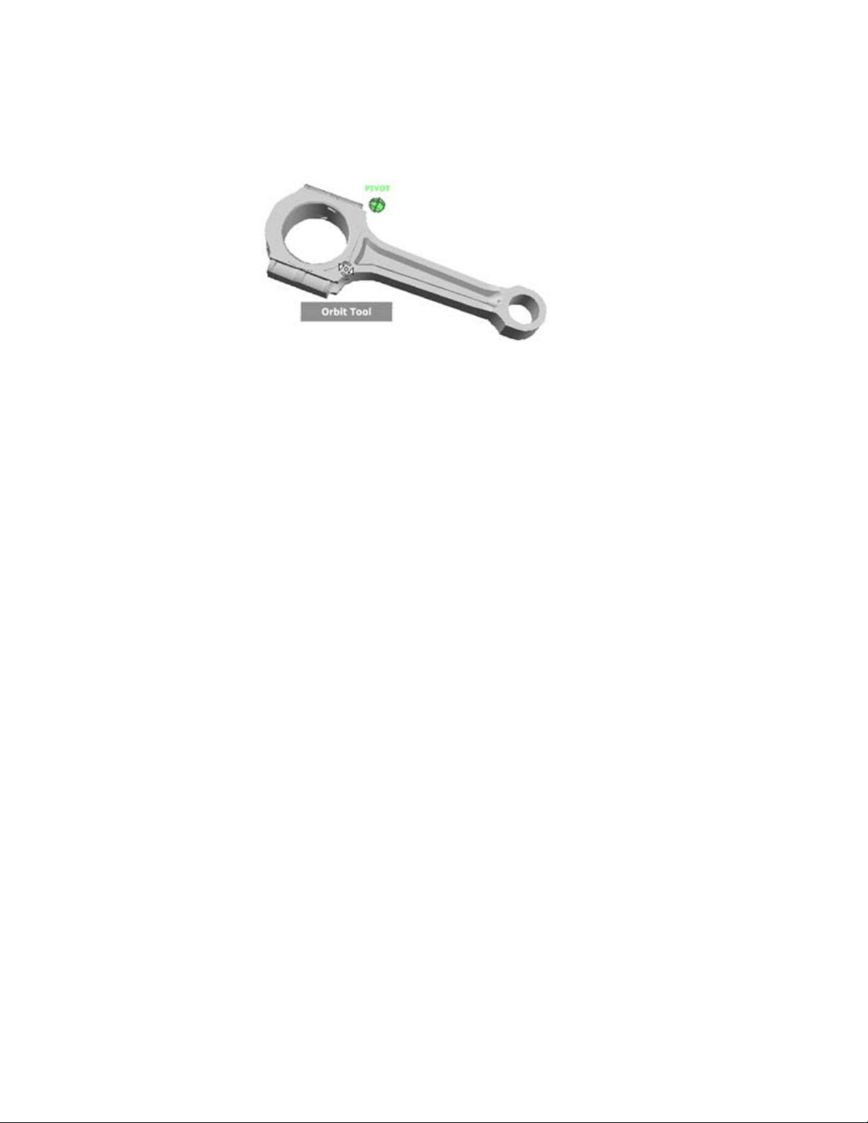
Orbit command
You use the Orbit command to change the orientation of a model. The cursor
changes to the Orbit cursor. As you drag the cursor, the model rotates around
a pivot point while the view remains fixed.
54 | Chapter 1 Autodesk Inventor Fusion TP2
Page 60
Specify the Pivot Point
The pivot point is the base point used when rotating the model with the Orbit
command. You can specify the pivot point in the following ways:
■ Default pivot point
. When you first open a model, the target point of the current view is used
as the pivot point for orbiting the model.
■ Select objects
. You can select objects before the Orbit command is used to calculate the
pivot point. The pivot point is calculated based on the center of the extents
of the selected objects.
■ Center command
. You can specify a point on the model to use as the pivot point for orbiting
with the NavSWheelCentercommand.htmCenter command .
■ Ctrl+Click and drag
. Press and hold down the
Ctrl
key before clicking the Orbit wedge or while the Orbit command is active.
Then drag to the point on the model to use as the pivot point. This option
is only available when using the big and mini Full Navigation wheels or
the mini View Object wheel. Note: While the Orbit command is active,
you can be press and hold the CTRL key at anytime to move the pivot
point used by the Orbit command.
Maintain Up Direction
You can control how the model orbits around the pivot point by choosing to
maintain the up direction of the model. When the up direction is maintained,
orbiting is constrained along the XY axis and in the Z direction. If you drag
Other commands in the Application Window | 55
Page 61
horizontally, the camera moves parallel to the XY plane. If you drag vertically,
the camera moves along the Z axis.
If the up direction is not maintained, you can roll the model using the roll
ring which is centered around the pivot point. Use the properties dialog box
for the SteeringWheels to control whether the up direction is maintained or
not for the Orbit command.
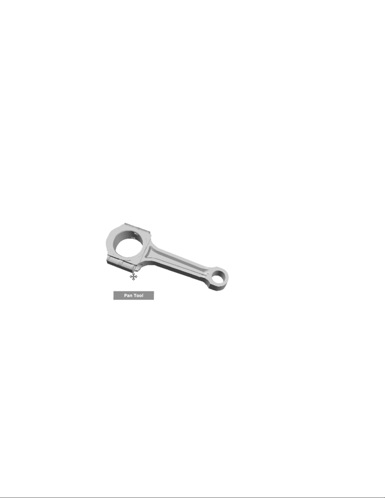
Pan command
When the Pan command is active, the Pan cursor (a four-sided arrow) is
displayed. Dragging the pointing device moves the model in the same
direction. For example, dragging upward moves the model up, while dragging
downward moves the model down.
In a 3D context, primarily when using 3D SteeringWheels, Pan dollies the
camera left and right. In a 2D context, Pan scrolls the view. If you are using
Pan with an active view on a sheet, Pan scrolls the sheet view, not the active
view on the sheet.
Tip: If the cursor reaches the edge of the screen, you can continue panning
by dragging further to force it to wrap around the screen.
Rewind command
As you use the navigation commands to reorient the view of a model, the
previous view is saved to the navigation history. The navigation history holds
a representation of the previous views of the model along with a thumbnail.
A separate navigation history is maintained for each window; it is not
maintained after the window is closed. Rewind navigation history is
view-specific.
56 | Chapter 1 Autodesk Inventor Fusion TP2
Page 62

With the Rewind command, you can retrieve previous views from the
navigation history. From the navigation history, you can restore a previous
view or scroll through all the saved views.
When you hold down the button on the pointing device over the Rewind
command on the wheel, the Rewind History panel is displayed. You can scroll
through the navigation history. To restore one of the previous views in the
navigation history, drag the bracket to the left in the Rewind History panel.
Note: Rewind history is not saved between sessions.
Walk command
With the Walk command, you can navigate through a model as if you were
walking through it. Once you start the Walk command, the Center Circle icon
is displayed near the center of the view. The cursor changes to display a series
of arrows. To walk through the model, you drag in the direction in which you
want to move in.
Constrain the Walk Angle
Other commands in the Application Window | 57
Page 63

When walking through a model, you can constrain the movement angle to
the ground plane. If the Constrain Walk Angle to Ground Plane option is
enabled, you can freely walk around while maintaining a constant camera
viewpoint elevation. If the walk angle is not constrained, you will fly in the
direction you are looking. Use the Properties dialog box for the SteeringWheels
to constrain the movement angle to the ground plane for the Walk command.
Movement Speed
As you walk or fly through a model, you can control the movement speed.
Movement speed is controlled by the distance in which the Cursor is moved
from the Center Circle icon and the current movement speed setting. You
can adjust the movement speed setting permanently or temporarily as you
use the Walk command. To adjust the movement speed permanently, use the
Properties dialog box for the SteeringWheels or the and keys when the Walk
command is active. To increase movement speed temporarily, press and hold
the + (plus) key while using the Walk command.
Change the Elevation
As you use the Walk command, adjust the camera elevation by holding down
the Shift key. It temporarily activates the Up/Down command. With the
Up/Down command active, drag up or down to adjust the elevation of the
camera. You can also use the UP ARROW and DOWN ARROW keys as you walk
to adjust the height of the view.
Zoom command
You use the Zoom command to change the zoom magnification of a model.
The following mouse click and key combinations are available to control how
the Zoom command behaves:
■ Click.
If you click the Zoom command on a wheel, the current view is zoomed
in by a factor of 25 percent. If you are using the Full Navigation wheel,
incremental zoom must be enabled in the Properties dialog box for the
SteeringWheels.
■ SHIFT+click.
If you hold down the
SHIFT
key before you click the Zoom command on a wheel, the current view is
zoomed out by a factor of 25 percent. Zooming is performed from the
current location of the cursor, and not the current pivot point. Note: When
58 | Chapter 1 Autodesk Inventor Fusion TP2
Page 64

you start the Zoom command from the Full Navigation wheel, incremental
zooming must be enabled in the Properties dialog box for the
SteeringWheels to use CTRL+click and SHIFT+click.
■ CTRL+click.
If you hold down the
CTRL
key before you click the Zoom command on a wheel, the current view is
zoomed in by a factor of 25 percent. Zooming is performed from the current
pivot point, and not the location of the cursor.
■ Click and drag.
If you click the Zoom command and hold down the button on your
pointing device, you can adjust the magnification of the model by dragging
up and down.
■ CTRL+click and drag.
When using the Full Navigation wheels or the mini View Object wheel,
you can control the target point used by the Zoom command. By holding
down the
CTRL
key, the Zoom command uses the location of the previous pivot point
defined by the Zoom, Orbit, or Center command.
■ SHIFT+click and drag.
When using the Full Navigation wheels or the mini View Object wheel,
zoom in to an area of the model by dragging a rectangular window around
the area to fit in the window. Hold down the
SHIFT
key and then click and drag a window around the area in which to zoom.
Note: If you hold down the CTRL key along with the SHIFT key, you can
zoom in to an area of a model using a center-based window, instead of
one defined by opposite corners.
■ Mouse wheel.
When a wheel is displayed, scroll the mouse wheel up or down to zoom
the view of the model in or out.
Note: When you use the Zoom command from the Full Navigation wheel or
the View Object wheel, the point in the view where you click to zoom becomes
the Center point for future Orbit operations until you either use the Zoom
command again or use the Center command. If you press CTRL before you
click the Zoom wedge, the Center point does not change.
Other commands in the Application Window | 59
Page 65

Zoom Constraints
When changing the magnification of a model with the Zoom command, you
cannot zoom in any closer than the focus point, or out any further past the
extents of the model. The direction you can zoom in and out is controlled by
the center point set by the Center command.
Note: Unlike the Zoom command on the big View Object wheel, the Zoom
command on the mini View Object wheel and the Full Navigation wheels are
not constrained.
Navigation Wheels
Wheels are available in two sizes: big and mini. The big wheel is larger than
the cursor. A label is on each wedge in the wheel. The mini wheel is about
the same size as the cursor. Labels are not displayed on the wheel wedges. The
2D Navigation wheel is only available in a big version.
2D Navigation Wheel
With this wheel, you can access basic 2D navigation commands; it is useful
when you do not have a pointing device with a scroll wheel. The wheel
includes the Pan and Zoom commands.
60 | Chapter 1 Autodesk Inventor Fusion TP2
Page 66
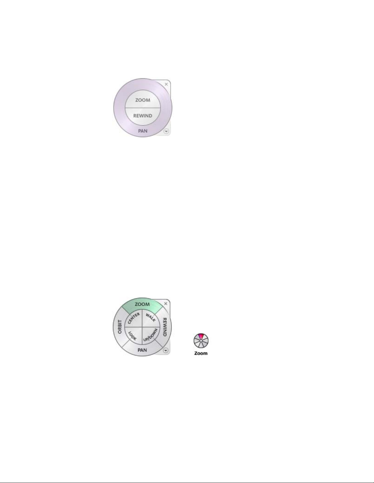
The 2D Navigation wheel wedges have the following options:
■ Pan:
Repositions the current view by panning.
■ Zoom:
Adjusts the magnification of the current view.
Note: Pan and Zoom in a 2D SteeringWheel are used to pan or zoom the
page space. In all other wheels, Pan and Zoom moves the camera.
■ Rewind:
Restores the most recent view orientation. You can move backward or
forward by clicking and dragging left or right.
Full Navigation Wheels
The Full Navigation wheels (big and mini) combine the 3D navigation
commands found on the View Object and Tour Building wheels. You can view
individual objects, and walk through and around a model. The big and mini
Full Navigation wheels are optimized for experienced 3D users.
Note: When one of the Full Navigation wheels is displayed, you can press and
hold the middle mouse button to pan, scroll the wheel button to zoom in
Other commands in the Application Window | 61
Page 67

and out, and hold the SHIFT key while pressing and holding the middle mouse
button to orbit the model.
Big Full Navigation Wheel
The big Full Navigation wheel wedges include the following options:
■ Zoom:
Adjusts the magnification of the current view.
■ Rewind:
Restores the most recent view. Move backward or forward by clicking and
dragging left or right.
■ Pan:
Repositions the current view by panning.
■ Orbit:
Rotates the current view around a fixed pivot point.
■ Center:
Specifies a point on a model to adjust the center of the current view or
change the target point used for some of the navigation commands.
■ Walk:
Simulates walking through a model.
■ Look:
Swivels the current view.
■ Up/Down:
Slides the current view of a model along the Z axis of the model.
Mini Full Navigation Wheel
The mini Full Navigation wheel wedges include the following options:
■ Zoom (Top wedge):
Adjusts the magnification of the current view.
■ Walk (Upper right wedge):
Simulates walking through a model.
■ Rewind (Right wedge):
Restores the most recent view. Move backward or forward by clicking and
dragging left or right.
62 | Chapter 1 Autodesk Inventor Fusion TP2
Page 68
■ Up/Down (Lower right wedge):
Slides the current view of a model along the Z axis of the model.
■ Pan (Bottom wedge):
Repositions the current view by panning.
■ Look (Lower left wedge):
Swivels the current view.
■ Orbit (Left wedge):
Rotates the current view around a fixed pivot point.
■ Center (Upper left wedge):
Specifies a point on a model to adjust the center of the current view or
change the target point used for some of the navigation commands.
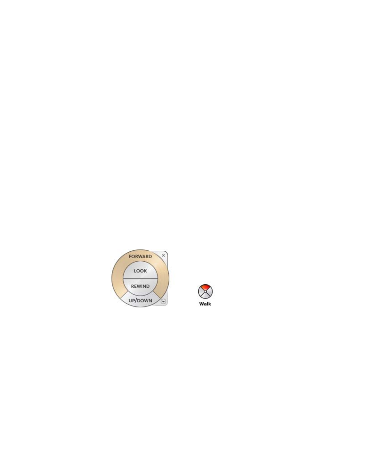
Tour Building Wheels
With the Tour Building wheels (big and mini), you can move through a model,
such as a building, assembly line, ship, or oil rig. You can also walk through
and navigate around a model. The big Tour Building wheel is optimized for
new 3D users while the mini Tour Building wheel is optimized for experienced
3D users.
Big Tour Building Wheel
The big Tour Building wheel wedges have the following options:
■ Forward:
Adjusts the distance between the current point of view and the defined
pivot point of the model. Clicking once moves forward half the distance
as far as the object you clicked.
■ Look:
Other commands in the Application Window | 63
Page 69

Swivels the current view.
■ Rewind:
Restores the most recent view. You can move backward or forward by
clicking and dragging left or right.
■ Up/Downcommand:
Slides the current view of a model along the Z axis of the model.
Mini Tour Building Wheel
The mini Tour Building wheel wedges have the following options:
■ Walk (Top wedge):
Simulates walking through a model.
■ Rewind (Right wedge):
Restores the most recent view. You can move backward or forward by
clicking and dragging left or right.
■ Up/Down (Bottom wedge):
Slides the current view of a model along the Z axis of the model.
■ Look (Left wedge):
Swivels the current view.
Note: When the mini wheel is displayed, you can press and hold the middle
mouse button to pan, scroll the wheel button to zoom in and out, and hold
the Shift key while pressing and holding the middle mouse button to orbit
the model.
View Object Wheels
With the View Object wheels (big and mini), you can view individual objects
or features in a model. The big View Object wheel is optimized for new 3D
users while the mini View Object wheel is optimized for experienced 3D users.
64 | Chapter 1 Autodesk Inventor Fusion TP2
Page 70

Big View Object Wheel
The big View Object wheel wedges have the following options:
■ Center:
Specifies a point on a model to adjust the center of the current view or
change the target point used for some of the navigation commands.
■ Zoom:
Adjusts the magnification of the current view.
■ Rewind:
Restores the most recent view orientation. You can move backward or
forward by clicking and dragging left or right.
■ Orbit:
Rotates the current view around a fixed pivot point.
Mini View Object Wheel
The mini View Object wheel wedges have the following options:
■ Zoom (Top wedge):
Adjusts the magnification of the current view.
■ Rewind (Right wedge):
Restores the most recent view. You can move backward or forward by
clicking and dragging left or right.
■ Pan (Bottom wedge):
Repositions the current view by panning.
■ Orbit (Left wedge):
Rotates the current view around a fixed pivot point.
Other commands in the Application Window | 65
Page 71
Note: When the mini wheel is displayed, you can press and hold the middle
mouse button to pan, scroll the wheel button to zoom in and out, and hold
the Shift key while pressing and holding the middle mouse button to orbit
the model.
Overview of SteeringWheels
SteeringWheels, also known as wheels, can save you time by combining many
of the common navigation commands into a single interface. Wheels are
specific to the context from which a model is being viewed.
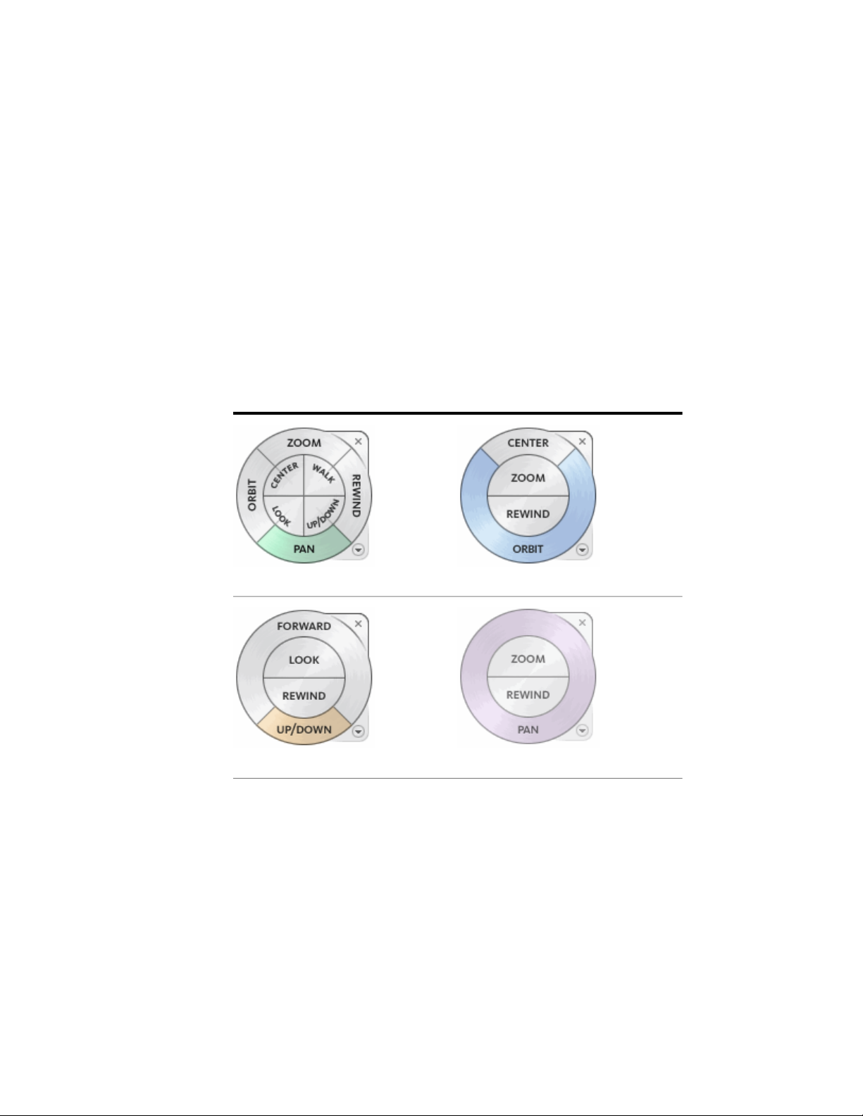
The following illustrations show the different wheels available:
Full Wheels
View Object WheelFull Navigation Wheel
66 | Chapter 1 Autodesk Inventor Fusion TP2
2D WheelTour Building Wheel
Page 72
Mini Wheels
Mini Full Navigation Wheel
Mini View Object Wheel
Mini Tour Building Wheel
Display and Use Wheels
Pressing and dragging on a wedge of a wheel is the primary mode of
interaction. After a wheel is displayed, click one of the wedges and hold down
the button on the pointing device to activate the navigation command. Drag
to reorient the current view. Releasing the button returns you to the wheel.
Appearance of the Wheels
You can control the appearance of the wheels by switching between the
different styles of wheels that are available, or by adjusting the size and opacity.
Wheels (except the 2D Navigation wheel) are available in two different styles:
big and mini.
The size of a wheel controls how large or small the wedges and labels appear
on the wheel; the opacity level controls the visibility of the objects in the
model behind the wheel.
Wheel tooltip, command Messages, and command Cursor Text
tooltips are displayed for each button on a wheel as the cursor is moved over
them. The tooltips appear below the wheel and identify what action to perform
if the wedge or button is clicked.
Similar to tooltips, command messages and cursor text are displayed when
you use one of the navigation commands from a wheel. command messages
are displayed when a navigation command is active; they provide basic
instructions about using the command. command cursor text displays the
Other commands in the Application Window | 67
Page 73

name of the active navigation command near the cursor. Disabling command
messages and cursor text only affects the messages that are displayed when
using the mini wheels or the big Full Navigation wheel.
Wheel Menu
Use the Wheel menu to switch between the big and mini wheels that are
available, go to the Home view, change the preferences of the current wheel,
and control the behavior of the orbit, look, and walk 3D navigation commands.
The menu items available on the Wheel menu are dependent on the current
wheel and program.
The Wheel menu has the following options:
■ Mini View Object Wheel.
■ Mini Tour Building Wheel.
■ Mini Full Navigation Wheel.
■ Full Navigation Wheel.
Displays the mini View Object wheel.
Displays the mini Tour Building wheel.
Displays the mini Full Navigation wheel.
Displays the big Full Navigation wheel.
■ Basic Wheels.
Displays the big View Object or Tour Building wheel.
■ Go Home.
Goes to the Home view saved with the model.
■ Fit to Window.
Resizes and centers the current view to display all objects.
■ Restore Original Center.
Restores the center point of the view to the extents of the model.
■ Level Camera.
Rotates the current view so it is relative to the XY ground plane.
■ Increase Walk Speed.
68 | Chapter 1 Autodesk Inventor Fusion TP2
Page 74

Increases the walk speed used for the Walk command by two times.
■ Decrease Walk Speed.
Decreases the walk speed used for the Walk command by one half.
■ Orient to View.
Orients the camera to match the view angle of the selected view (a plan,
elevation, section, or 3D view).
■ Orient to a Plane.
Adapts the view according to a specific plane.
■ Save View.
Saves the current view orientation with a unique name.Note: Use Save
View only to save a 3D view with a unique name when you are viewing
the default 3D view. If you are viewing a previously saved orthographic
3D view or a perspective (camera) 3D view, the view is saved with the new
orientation and you are not prompted to supply a unique name.
■ Increase/Decrease Focal Length.
Acts as a zoom lens on the model, because it changes the focal length of
the camera in a perspective view.
■ Move Crop Boundary.
Moves the position of the crop boundary around in a perspective view.
■ Re-center Crop Boundary.
Repositions the crop boundary to the center of the perspective view.
■ Help.
Displays the Help system and displays the topic about the wheels.
■ Properties.
Displays the dialog box where you can adjust the preferences for the wheels.
■ Close Wheel.
Closes the wheel.
Other commands in the Application Window | 69
Page 75

Procedure
■ Click the down arrow in the lower-right corner of the wheel or right-click
the wheel.
Navigation Bar
The navigation bar is a user interface element from which you can access both
unified and product-specific navigation commands. Unified navigation
commands (such as Autodesk ViewCube and SteeringWheels) can be found
across many Autodesk products. Product-specific navigation commands are
unique to a product. The navigation bar floats over and along one of the sides
of the window of the current model.
The unified and product-specific navigation commands are organized into
separate areas of the navigation bar. The unified navigation commands are
located on the two ends of the navigation bar, while the product-specific
navigation commands are located in the center. Start navigation commands
by clicking one of the buttons on the navigation bar. Or, select one of the
commands from a list that is displayed when you click the smaller portion of
a split button.
Available Navigation commands
The following unified navigation commands are available from the navigation
bar:
■ ViewCube.
Indicates the current orientation of a model and is used to reorient the
current view of a model.
■ SteeringWheels.
70 | Chapter 1 Autodesk Inventor Fusion TP2
Page 76

Collection of wheels that offer rapid switching between specialized
navigation commands.
The following product-specific navigation commands are available from the
navigation bar:
■ Pan.
Moves the view parallel to the screen.
■ Zoom commands.
Set of navigation commands for increasing or decreasing the magnification
of the current view of a model.
■ Orbit commands.
Set of navigation commands for rotating the current view of a model.
■ Look At.
Views faces of a model from a selected plane.
Reposition and Reorient the Navigation Bar
Adjust the position and orientation of the navigation bar by linking it to the
ViewCube, docking it when the ViewCube is not displayed, or freely
positioning it along one of the edges of the current window. When linked to
the ViewCube, the navigation bar is positioned above or below the ViewCube
and in a vertical orientation. When not linked or docked, the navigation bar
can be freely aligned along one of the edges of the window of the current
model.
You specify how the navigation bar can be repositioned from the Customize
menu. When not linked to the ViewCube or docked, a grip handle is displayed.
Drag the grip handle on the navigation bar to reposition it along one of the
sides of the window of the current window.
If the side of the window that the navigation bar is aligned to is not long
enough to show the entire navigation bar, it is truncated to fit. When
truncated, a More Controls button is displayed and replaces the Customize
button. When you click the More Controls button, a menu is displayed that
contains the navigation commands that are not currently being displayed.
Control the Display of Navigation commands on the Navigation Bar
You can control which unified and product-specific navigation commands
are displayed on the navigation bar with the Customize menu by clicking the
drop-down arrow located on the bottom right of the navigation bar. The
Customize menu is displayed by clicking the Customize button. From the
Other commands in the Application Window | 71
Page 77

Customize menu, you click the navigation commands to display on the
navigation bar. The position of the navigation commands on the navigation
bar is predefined and cannot be changed.
Create 3D Models
This section describes some common techniques that are used in Inventor
Fusion to create designs. It covers a wide range of modeling techniques that
can be used to create and edit model geometry and components in an Inventor
Fusion design. First, a few notes about the nature of an Inventor Fusion design.
The following image is an example of a simple Fusion design:
72 | Chapter 1 Autodesk Inventor Fusion TP2
Page 78

This simple design has some elements that are worth pointing out:
1 The Bodies folder in the browser. This folder contains all of the bodies
for a component. This example has a single body Body1.
2 The Body node in the browser. Each body owned by the component has
an entry in the Bodies folder.
3 The Sketches folder in the browser. This folder contains all of the sketches
for a component. This example has a single sketch, which is invisible
(the light bulb icon shows the visibility state for many items in a Fusion
design).
4 The Sketch node in the browser. Each sketch owned by the component
has an entry in the Sketches folder.
5 Feature nodes in the browser. These items represent geometry which has
been create using a feature command in Fusion. In this example, the
design has two features: Extrude1, and Hole2. The nodes underneath
Feature nodes show individual body faces that were created by that
feature.
Create 3D Models | 73
Page 79

6 The component body. The graphics area shows the geometry of the
component. Most operations are performed by the user on this
representation of the component.
An Inventor Fusion design may also contain:
■ Multiple bodies
■ Work geometry
■ Annotation planes and annotations
■ Named views
■ Child components
An example of a more complex design is shown here:
Points of interest:
■ The design contains a second body.
■ The design contains a work axis.
■ The design contains a child component (Component2).
■ The design contains a second-level of component (Component3).
74 | Chapter 1 Autodesk Inventor Fusion TP2
Page 80
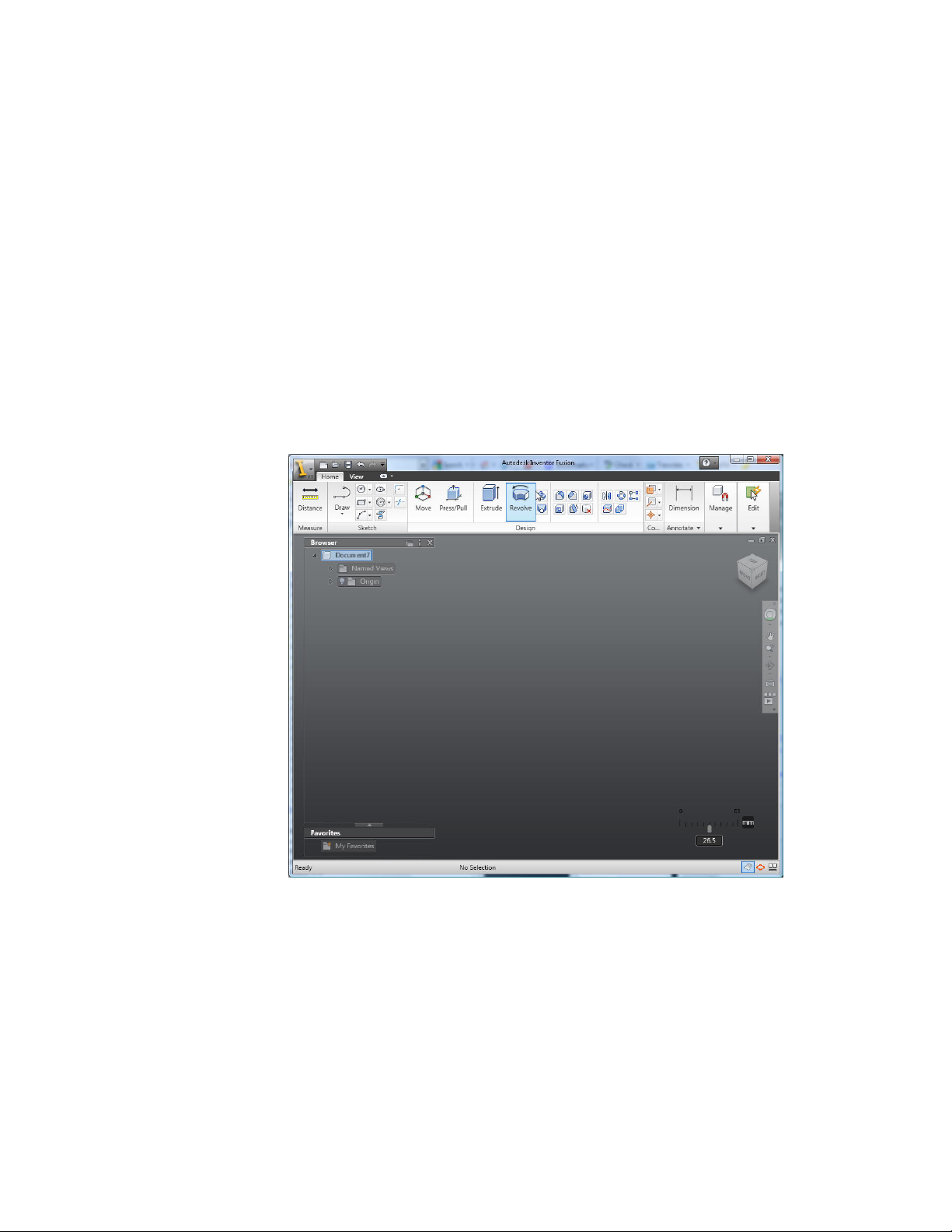
Create a Single Body
These steps illustrate how to start with an empty Fusion document, and create
a single body in a simple design.
This example uses these Inventor Fusion capabilities:
■ Sketching: Sketch on page 135
■ Feature creation: Features on page 177
Starting point: An empty design
This example begins with an empty design. This is the state when Fusion is
first invoked, or when the New icon is clicked. It looks like:
Step 1: Create a sketch rectangle
click the Rectangle command in the Ribbon
Create a Single Body | 75
Page 81

Because no sketch is currently active, the first step is to create a new sketch.
Select one of the origin work planes. In this example, we select the XY plane:
76 | Chapter 1 Autodesk Inventor Fusion TP2
Page 82

This creates and activates a new sketch, changes the view to look at the new
sketch, and invokes the Rectangle command:
Create a Single Body | 77
Page 83
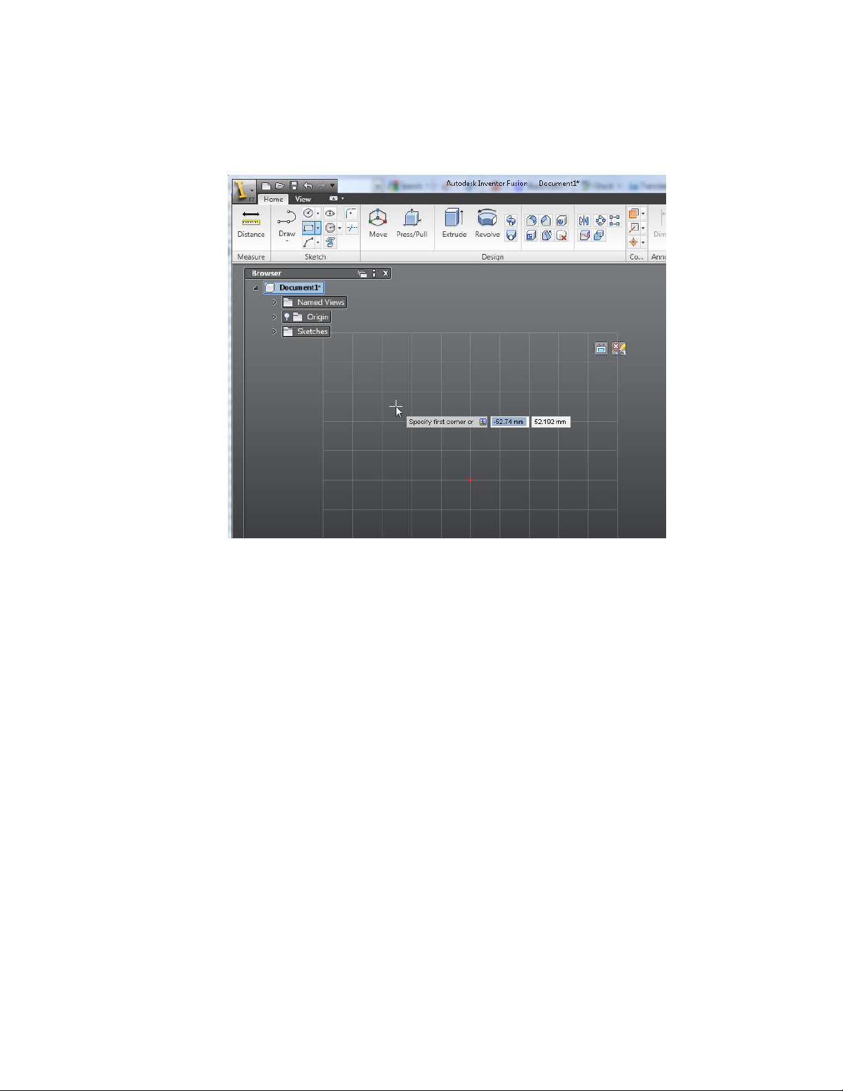
Click a first and second point to describe the rectangle:
78 | Chapter 1 Autodesk Inventor Fusion TP2
Page 84

As soon as the rectangle is finished, Inventor Fusion recognizes the closed
region, and shades it in a yellow color:
Create a Single Body | 79
Page 85

Step 2: Extrude the rectangle
80 | Chapter 1 Autodesk Inventor Fusion TP2
Page 86
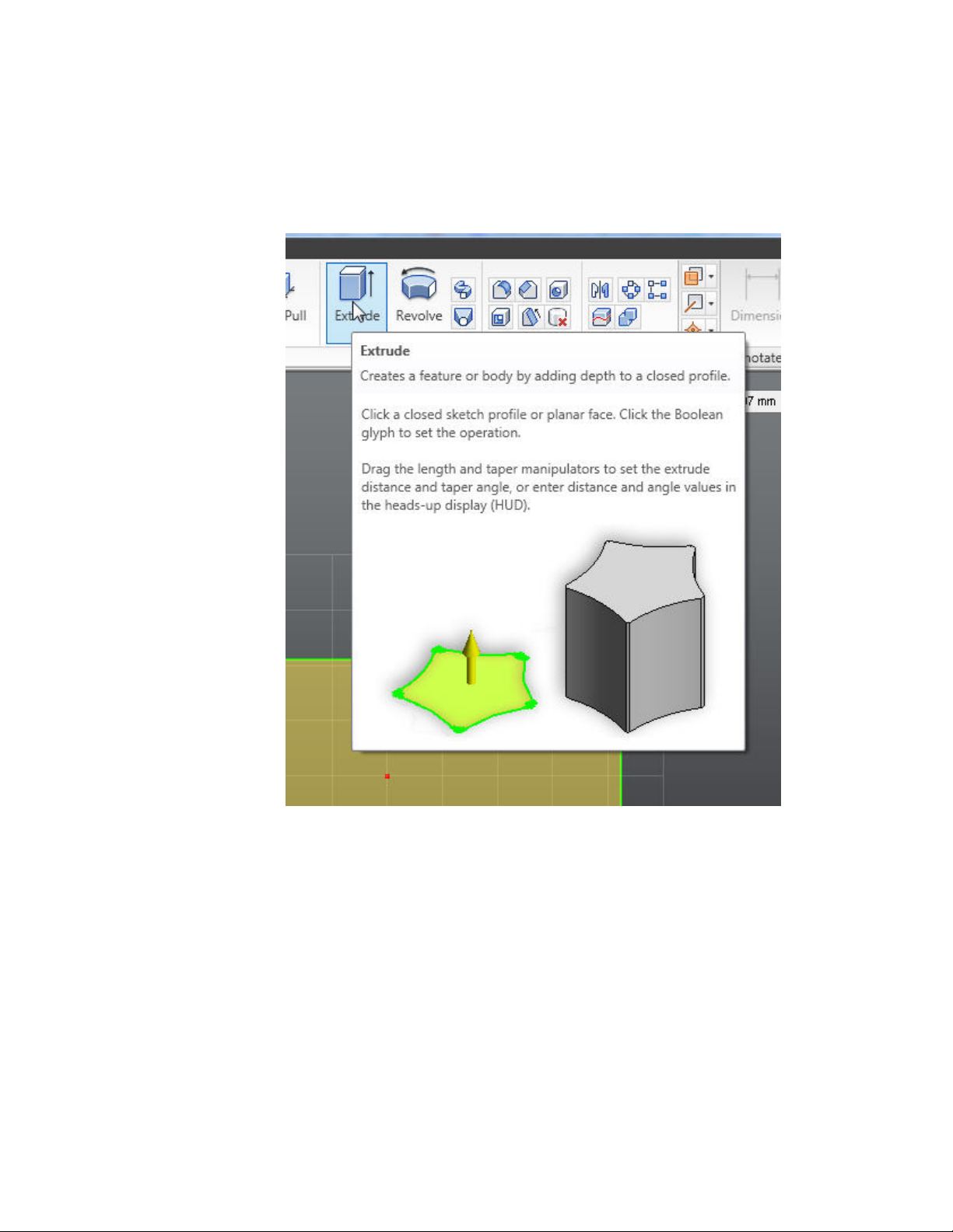
Invoke the Extrude command. There are several ways to invoke Extrude. For
this simple example, choose the Extrude command in the ribbon:
Because there is only a single closed region, Fusion automatically selects it.
If more than one closed region were available, you would be required to
explicitly select which region to use. Extrude shows the following elements:
Create a Single Body | 81
Page 87

Note that these elements are also present in the ribbon, but are much more
convenient to interact with in the graphics area
Drag to change the depth of the extrusion. You may drag over empty space,
or directly over the distance manipulator. Dragging produces a preview of
the extrusion:
82 | Chapter 1 Autodesk Inventor Fusion TP2
Page 88

Finish the command. There are a couple of ways to complete the command
- starting another command, or clicking OK in the ribbon. In this case, click
OK in the ribbon. This creates the body, as well as an Extrude feature in the
browser:
Create a Single Body | 83
Page 89

Create Multiple Bodies
The steps in this topic illustrate how to create a second body, starting with a
Fusion document containing a single body, and create a second body. This
example uses these Inventor Fusion capabilities:
■ Sketching Sketch on page 135
■ Feature creation Features on page 177
Starting point: a design containing a single body, in the root component
This is what the starting point for this example looks like:
84 | Chapter 1 Autodesk Inventor Fusion TP2
Page 90

To learn how to create a design similar to this see: Create a Single Body on
page 75
Step 1: Create a sketch and a sketch circle
click the Circle command in the Ribbon
Because no sketch is currently active, the first step is to create a new sketch.
Select a face of the existing body.
Create Multiple Bodies | 85
Page 91

This creates and activates a new sketch, changes the view to look at the new
sketch, and invokes the Circle command. Select a circle center and radius
point, away from the existing body. Note that because we selected a face of
the existing body, Fusion has generated sketch geometry that coincides with
the edges of that face. This sketch geometry is fixed, and so can't be edited.
86 | Chapter 1 Autodesk Inventor Fusion TP2
Page 92
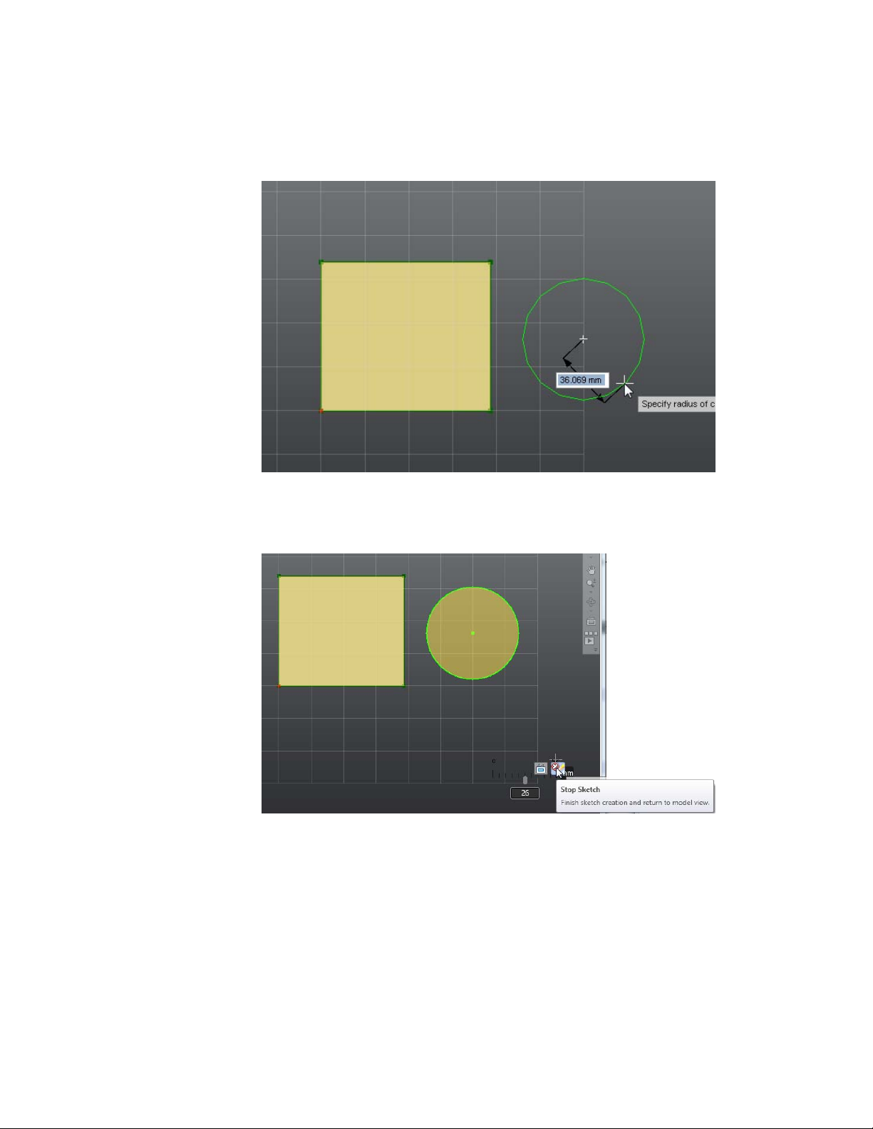
Step 2: Exit the sketch
In this example we illustrate how to exit sketch edit mode. click the Stop
Sketch icon in the lower left corner of the screen.
This terminates the active sketch, and restores the view to where it was before
sketching:
Create Multiple Bodies | 87
Page 93

Note that Fusion recognizes the two closed regions, and shades them in a
yellow color.
Step 3: Create a second body using the Revolve feature
Invoke the Revolve command. There are several ways to invoke Revolve. For
this simple example, we use the context menu.
Select the circular closed region, using the left mouse button. Click or hold
down the right mouse button to bring up the marking menu and the context
menu. Choose the Revolve command from the context menu:
88 | Chapter 1 Autodesk Inventor Fusion TP2
Page 94

This brings up the Revolve command, with the circular region as the profile
to Revolve.
Revolve requires a second selection - an axis to revolve about. click the Axis
glyph:
Create Multiple Bodies | 89
Page 95

This prompts you to select an axis. You can select sketch lines or linear edges.
In this case we select a sketch line from the face we sketched on:
Once the axis is selected, begin dragging. In this example, we will drag in an
area that is away from the manipulator. Click and drag the left mouse button
in an area of the screen that is not over any graphics. The example drags to
90 | Chapter 1 Autodesk Inventor Fusion TP2
Page 96

the upper right area of the screen. Note that the drag for Revolve,when
dragging in open space is a 2-dimensional drag in the plane of the screen.
Next, change the Operation Type of the Revolve feature to create a new body.
Click and hold down the left mouse button over the Operation Type glyph,
and choose New Body.
Create Multiple Bodies | 91
Page 97

Finally, click OK in the ribbon to create the Revolve and the new body. The
results look like:
92 | Chapter 1 Autodesk Inventor Fusion TP2
Page 98
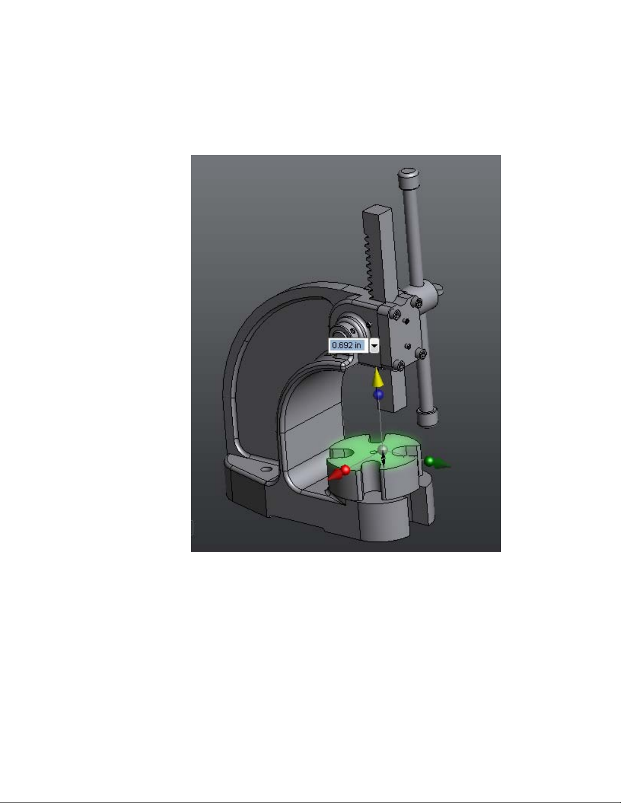
Modify a Body
This section discusses how to modify an already-existing geometric body in
a Fusion design. This is one of the strengths of Inventor Fusion, and one of
the main workflows for new users to understand to be productive when using
Fusion.
Modify a Body | 93
Page 99
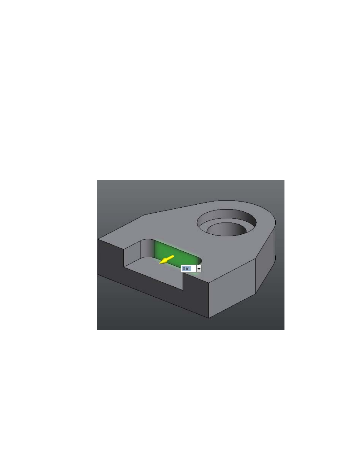
Inventor Fusion provides a highly interactive environment for geometric
editing. You can drag faces of the body into a variety of new positions using
the commands described in the following section.
Related Topics:
■ Dimensions and Body Constraints on page 184
Press/Pull Command
The Press/Pull command is one way that a user can modify body geometry.
In general, Press/Pull provides users with an Offset style of modification. That
is, the modified geometry is replaced with an offset of itself.
For instance, in this simple design, the user can select a face such as this one:
Resulting in this geometry:
94 | Chapter 1 Autodesk Inventor Fusion TP2
Page 100

Multiple Faces
Press/Pull can be applied to multiple faces at once:
Modify a Body | 95
 Loading...