

Page 1

Autodesk Inventor 2010
Getting Started
January 2009Part No. 527B1-050000-PM01A
Page 2

©
2009 Autodesk, Inc. All Rights Reserved. Except as otherwise permitted by Autodesk, Inc., this publication, or parts thereof, may not be
reproduced in any form, by any method, for any purpose.
Certain materials included in this publication are reprinted with the permission of the copyright holder.
Trademarks
The following are registered trademarks or trademarks of Autodesk, Inc., in the USA and other countries: 3DEC (design/logo), 3December,
3December.com, 3ds Max, ADI, Alias, Alias (swirl design/logo), AliasStudio, Alias|Wavefront (design/logo), ATC, AUGI, AutoCAD, AutoCAD
Learning Assistance, AutoCAD LT, AutoCAD Simulator, AutoCAD SQL Extension, AutoCAD SQL Interface, Autodesk, Autodesk Envision, Autodesk
Insight, Autodesk Intent, Autodesk Inventor, Autodesk Map, Autodesk MapGuide, Autodesk Streamline, AutoLISP, AutoSnap, AutoSketch,
AutoTrack, Backdraft, Built with ObjectARX (logo), Burn, Buzzsaw, CAiCE, Can You Imagine, Character Studio, Cinestream, Civil 3D, Cleaner,
Cleaner Central, ClearScale, Colour Warper, Combustion, Communication Specification, Constructware, Content Explorer, Create>what's>Next>
(design/logo), Dancing Baby (image), DesignCenter, Design Doctor, Designer's Toolkit, DesignKids, DesignProf, DesignServer, DesignStudio,
Design|Studio (design/logo), Design Web Format, Discreet, DWF, DWG, DWG (logo), DWG Extreme, DWG TrueConvert, DWG TrueView, DXF,
Ecotect, Exposure, Extending the Design Team, Face Robot, FBX, Filmbox, Fire, Flame, Flint, FMDesktop, Freewheel, Frost, GDX Driver, Gmax,
Green Building Studio, Heads-up Design, Heidi, HumanIK, IDEA Server, i-drop, ImageModeler, iMOUT, Incinerator, Inferno, Inventor, Inventor
LT, Kaydara, Kaydara (design/logo), Kynapse, Kynogon, LandXplorer, LocationLogic, Lustre, Matchmover, Maya, Mechanical Desktop, Moonbox,
MotionBuilder, Movimento, Mudbox, NavisWorks, ObjectARX, ObjectDBX, Open Reality, Opticore, Opticore Opus, PolarSnap, PortfolioWall,
Powered with Autodesk Technology, Productstream, ProjectPoint, ProMaterials, RasterDWG, Reactor, RealDWG, Real-time Roto, REALVIZ,
Recognize, Render Queue, Retimer,Reveal, Revit, Showcase, ShowMotion, SketchBook, Smoke, Softimage, Softimage|XSI (design/logo),
SteeringWheels, Stitcher, Stone, StudioTools, Topobase, Toxik, TrustedDWG, ViewCube, Visual, Visual Construction, Visual Drainage, Visual
Landscape, Visual Survey, Visual Toolbox, Visual LISP, Voice Reality, Volo, Vtour, Wire, Wiretap, WiretapCentral, XSI, and XSI (design/logo).
The following are registered trademarks or trademarks of Autodesk Canada Co. in the USA and/or Canada and other countries:
Backburner,Multi-Master Editing, River, and Sparks.
The following are registered trademarks or trademarks of MoldflowCorp. in the USA and/or other countries: Moldflow, MPA, MPA
(design/logo),Moldflow Plastics Advisers, MPI, MPI (design/logo), Moldflow Plastics Insight,MPX, MPX (design/logo), Moldflow Plastics Xpert.
All other brand names, product names or trademarks belong to their respective holders.
Disclaimer
THIS PUBLICATION AND THE INFORMATION CONTAINED HEREIN IS MADE AVAILABLE BY AUTODESK, INC. "AS IS." AUTODESK, INC. DISCLAIMS
ALL WARRANTIES, EITHER EXPRESS OR IMPLIED, INCLUDING BUT NOT LIMITED TO ANY IMPLIED WARRANTIES OF MERCHANTABILITY OR
FITNESS FOR A PARTICULAR PURPOSE REGARDING THESE MATERIALS.
Published by:
Autodesk, Inc.
111 Mclnnis Parkway
San Rafael, CA 94903, USA
Page 3

Contents
Chapter 1 Digital Prototypes in Autodesk Inventor . . . . . . . . . . . . . . 1
Digital Prototype Workflow . . . . . . . . . . . . . . . . . . . . . . . . 1
Components of Digital Prototypes (file types) . . . . . . . . . . . . . . . 3
Associative Behavior of Parts . . . . . . . . . . . . . . . . . . . . . 7
Associative Behavior of Assemblies . . . . . . . . . . . . . . . . . . 7
Associative Behavior of Drawings . . . . . . . . . . . . . . . . . . 8
Chapter 2 Create Digital Prototypes . . . . . . . . . . . . . . . . . . . . . 9
Parts . . . . . . . . . . . . . . . . . . . . . . . . . . . . . . . . . . . . . 9
Single Body Parts . . . . . . . . . . . . . . . . . . . . . . . . . . 10
iParts . . . . . . . . . . . . . . . . . . . . . . . . . . . . . . . . . 10
Sheet Metal Parts . . . . . . . . . . . . . . . . . . . . . . . . . . 11
Derived Parts . . . . . . . . . . . . . . . . . . . . . . . . . . . . 13
Multi-body Parts . . . . . . . . . . . . . . . . . . . . . . . . . . . 14
Shrinkwrap Parts . . . . . . . . . . . . . . . . . . . . . . . . . . 14
Assembly Substitute Parts . . . . . . . . . . . . . . . . . . . . . . 15
Content Center Parts . . . . . . . . . . . . . . . . . . . . . . . . 16
Content Center Libraries . . . . . . . . . . . . . . . . . . . 18
Features . . . . . . . . . . . . . . . . . . . . . . . . . . . . . . . . . . 18
Sketched Features . . . . . . . . . . . . . . . . . . . . . . . . . . 19
Sketch Environment . . . . . . . . . . . . . . . . . . . . . 23
Sketch Blocks . . . . . . . . . . . . . . . . . . . . . . . . . 24
Sketch Constraints . . . . . . . . . . . . . . . . . . . . . . 25
iii
Page 4

2D AutoCAD Data in Sketches . . . . . . . . . . . . . . . . 25
Placed Features . . . . . . . . . . . . . . . . . . . . . . . . . . . 26
iFeatures . . . . . . . . . . . . . . . . . . . . . . . . . . . . . . . 27
Assembly Features . . . . . . . . . . . . . . . . . . . . . . . . . . 27
Work Features . . . . . . . . . . . . . . . . . . . . . . . . . . . . 28
Edit Features . . . . . . . . . . . . . . . . . . . . . . . . . . . . . 29
Assemblies . . . . . . . . . . . . . . . . . . . . . . . . . . . . . . . . . 29
Place Components . . . . . . . . . . . . . . . . . . . . . . . . . 30
Drag Components into Assemblies . . . . . . . . . . . . . . 31
Assembly Constraints . . . . . . . . . . . . . . . . . . . . . . . . 31
Degrees of Freedom . . . . . . . . . . . . . . . . . . . . . . 32
Top-down Design . . . . . . . . . . . . . . . . . . . . . . . . . . 33
Create Subassemblies In-place . . . . . . . . . . . . . . . . . . . 33
Design Accelerator Components . . . . . . . . . . . . . . . . . . 34
Design Mechanisms . . . . . . . . . . . . . . . . . . . . . . . . . 35
Check for Interference . . . . . . . . . . . . . . . . . . . . . . . 37
iAssemblies . . . . . . . . . . . . . . . . . . . . . . . . . . . . . 38
Chapter 3 Document and Publish Designs . . . . . . . . . . . . . . . . . . 39
Drawings . . . . . . . . . . . . . . . . . . . . . . . . . . . . . . . . . . 39
Start Drawings . . . . . . . . . . . . . . . . . . . . . . . . . . . . 39
Types of Drawing Files . . . . . . . . . . . . . . . . . . . . . . . 40
Create Views of Models . . . . . . . . . . . . . . . . . . . . . . . 41
Types of Drawing Views . . . . . . . . . . . . . . . . . . . . 41
Drawing View Operations . . . . . . . . . . . . . . . . . . . 43
Drawing View Tips . . . . . . . . . . . . . . . . . . . . . . 44
Exploded Views . . . . . . . . . . . . . . . . . . . . . . . . . . . 45
Annotate Drawing Views . . . . . . . . . . . . . . . . . . . . . . 45
Types of Drawing Annotations . . . . . . . . . . . . . . . . 46
Styles and Standards . . . . . . . . . . . . . . . . . . . . . . . . 50
Studio in Autodesk Inventor . . . . . . . . . . . . . . . . . . . . . . . 51
Publish Designs . . . . . . . . . . . . . . . . . . . . . . . . . . . . . . 53
Chapter 4 Manage Data . . . . . . . . . . . . . . . . . . . . . . . . . . . 55
Share Files in Work Groups Using Vault . . . . . . . . . . . . . . . . . 55
Autodesk Vault Add-ins for Design Applications . . . . . . . . . . 56
Microsoft Office Add-ins . . . . . . . . . . . . . . . . . . . . . . 57
Copy Designs Using Vault . . . . . . . . . . . . . . . . . . . . . 57
Share Files Externally . . . . . . . . . . . . . . . . . . . . . . . . . . . 57
Autodesk Vault Manufacturing . . . . . . . . . . . . . . . . . . . 58
Autodesk Design Review . . . . . . . . . . . . . . . . . . . . . . 58
Import and Export Data . . . . . . . . . . . . . . . . . . . . . . . . . . 59
AutoCAD Files . . . . . . . . . . . . . . . . . . . . . . . . . . . . 59
Import Files from Other CAD Systems . . . . . . . . . . . . . . . 61
Export Files to Other CAD System Formats . . . . . . . . . . . . . 62
iv | Contents
Page 5

Chapter 5 Set Your Environment . . . . . . . . . . . . . . . . . . . . . . . 63
Commands and Tools . . . . . . . . . . . . . . . . . . . . . . . . . . . 63
Environment Preferences . . . . . . . . . . . . . . . . . . . . . . . . . 65
Application Options . . . . . . . . . . . . . . . . . . . . . . . . . 65
Document Settings . . . . . . . . . . . . . . . . . . . . . . . . . 65
Styles and Standards . . . . . . . . . . . . . . . . . . . . . . . . . . . . 65
Style Libraries . . . . . . . . . . . . . . . . . . . . . . . . . . . . 66
Views of Models . . . . . . . . . . . . . . . . . . . . . . . . . . . . . . 66
Templates . . . . . . . . . . . . . . . . . . . . . . . . . . . . . . . . . 67
Projects . . . . . . . . . . . . . . . . . . . . . . . . . . . . . . . . . . 68
Vault Projects . . . . . . . . . . . . . . . . . . . . . . . . . . . . 69
Default Projects . . . . . . . . . . . . . . . . . . . . . . . . . . . 70
New Projects . . . . . . . . . . . . . . . . . . . . . . . . . . . . . 70
Learning Resources . . . . . . . . . . . . . . . . . . . . . . . . . . . . 71
New Features Workshop . . . . . . . . . . . . . . . . . . . . . . . 71
Integrated Help . . . . . . . . . . . . . . . . . . . . . . . . . . . 71
Tutorials . . . . . . . . . . . . . . . . . . . . . . . . . . . . . . . 72
Skill Builders . . . . . . . . . . . . . . . . . . . . . . . . . . . . . 73
Index . . . . . . . . . . . . . . . . . . . . . . . . . . . . . . . . 75
Contents | v
Page 6

vi
Page 7

Digital Prototypes in Autodesk Inventor
Autodesk Inventor® provides a comprehensive set of 3D mechanical CAD tools for producing,
validating, and documenting complete digital prototypes. The Inventor model is a 3D digital
prototype. The prototype helps you visualize, simulate, and analyze how a product or part
works under real-world conditions before it is built. Manufacturers get to market faster with
fewer physical prototypes and more innovative products.
Inventor provides an intuitive 3D design environment for creating parts and assemblies.
Engineers can focus on the function of a design to drive the automatic creation of intelligent
components, such as steel frames, rotating machinery, tube and pipe runs, electrical cables,
and wire harnesses.
Tightly integrated motion simulation and stress analysis in Inventor are easy to use. They
make it possible for engineers to optimize and validate the digital prototype.
Generating manufacturing documentation from a validated 3D digital prototype reduces
errors and associated engineering change orders (ECOs) before manufacturing. Inventor offers
rapid and accurate output of production-ready drawings directly from the 3D model.
Inventor is tightly integrated with Autodesk® data management applications. This integration
enables the efficient and secure exchange of digital design data and promotes earlier
collaboration between design and manufacturing workgroups. Different workgroups can
manage and track all components of a digital prototype with Autodesk® Design Review
software. This software is the all-digital way to review, measure, mark up, and track changes
to designs. You can better reuse crucial design data, manage bills of materials (BOMs), and
collaborate with other teams and partners.
1
Digital Prototype Workflow
Before you start a design, determine the most efficient workflow. A top down
workflow is often the most efficient way to create a design. In a top down
1
Page 8

workflow, you design your components in the context of other components.
This method can greatly reduce errors in form, fit, and function.
Some examples of a top-down workflow are:
■ Create new parts or sub-assemblies in the destination assembly.
■ Create multiple solid bodies in a part file and then save the individual
bodies as unique parts.
■ Create 2D sketch blocks in a part file to simulate a mechanism. You can
use the sketch blocks to create 3D components in an assembly that is
controlled by the layout.
Following are questions to consider before you start:
■ Which view of the part best describes the basic shape?
■ Is the part a sheet metal part?
■ Can this part be used as a part factory (iPart) to generate multiple parts?
■ Can a spreadsheet control one or more parts?
■ Can I create the part automatically by using a Design Accelerator?
■ If the part is a component in a structural steel frame, can I use Frame
Generator to create the entire frame?
■ If the part is a common library part, does it exist in the Content Center or
other library?
The following image shows a multi-body part file saved as individual parts in
an assembly. Individual bodies in a multi-body part file can share features
with other bodies such as fillets and holes.
2 | Chapter 1 Digital Prototypes in Autodesk Inventor
Page 9

LocationFor more information
Search: “Multi-body parts”Help topic
Parts 1 - Create PartsTutorial
PartsSkill Builders
Components of Digital Prototypes (file types)
Create or activate a project file before you open an existing file or start a new
file to set the file location. Click New to see the New File dialog box with
templates for a new part, assembly, presentation file, sheet metal part,
weldment, or drawing. You can choose from several templates with predefined
units.
A template can contain property information, such as part and project data,
and drawing views. You can see information stored in a file by viewing its
properties.
For more information about templates, see Templates on page 67. For more
information about projects, see Projects on page 68.
For more information about projects, see Projects on page 68.
Components of Digital Prototypes (file types) | 3
Page 10

Part (.ipt) Files
When you open a part file, you are in the part environment. Part tools
manipulate sketches, features, and bodies which combine to make parts. You
can insert a single body part into assemblies and constrain them in positions
they occupy when the assembly is manufactured. You can extract multiple
part files from a multi-body part.
Most parts start with a sketch. A sketch is the profile of a feature and any
geometry (such as a sweep path or axis of rotation) required to create the
feature.
A part model is a collection of features. If necessary, solid bodies in a
multi-body part file can share features. Sketch constraints control geometric
relationships such as parallel and perpendicular. Dimensions control the size.
Collectively this method is called Parametric modeling. You can adjust the
constraints or dimensional parameters that control the size and shape of a
model, and automatically see the effect of your modifications.
The following image shows a single body part in the upper half of the image,
and a multi-body part in the lower half of the image. Notice the different part
icons in each image.
Assembly (.iam) Files
In Autodesk Inventor, you place components that act as a single functional
unit into an assembly document. Assembly constraints define the relative
position these components occupy with respect to each other. An example is
the axis of a shaft aligning with a hole in a different component.
4 | Chapter 1 Digital Prototypes in Autodesk Inventor
Page 11

When you create or open an assembly file, you are in the assembly
environment. Assembly tools manipulate whole subassemblies and assemblies.
You can group parts that function together as a single unit and then insert
the subassembly into another assembly.
You can insert parts into an assembly or use sketch and part tools to create
parts in the context of an assembly. During these operations, all other
components in the assembly are visible.
To complete a model, you can create assembly features that affect multiple
components, such as holes that pass through multiple parts. Assembly features
often describe specific manufacturing processes such as post-machining.
The assembly browser is a convenient way to activate components you want
to edit. Use the browser to edit sketches, features, and constraints, turn
component visibility on and off, and do other tasks. In the following image
of an assembly, two of the components display an icon indicating they are
part of a contact set. Components that belong to a contact set behave as they
would in the physical world.
Presentation (.ipn) Files
Presentation files are a multi-purpose file type. Use a presentation file to:
■ Create an exploded view of an assembly to use in a drawing file.
■ Create an animation which shows the step by step assembly order. The
animation can contain view changes and the visibility state of components
at each step in the assembly process. You can save the animation to a .wmv
or .avi file format.
Components of Digital Prototypes (file types) | 5
Page 12

Drawing (.idw, .dwg) Files
After you create a model, you can create a drawing to document your design.
In a drawing, you place views of a model on one or more drawing sheets. Then
you add dimensions and other drawing annotations to document the model.
A drawing that documents an assembly can contain an automated parts list
and item balloons in addition to the required views.
The templates to use as the starting point for your drawings have the standard
drawing file extension (.idw, .dwg).
6 | Chapter 1 Digital Prototypes in Autodesk Inventor
Page 13

Autodesk Inventor maintains links between components and drawings, so
you can create a drawing at any time during the creation of a component. By
default, the drawing updates automatically when you edit the component.
However, it is a good idea to wait until a component design is nearly complete
before you create a drawing. Edit the drawing details (to add or delete
dimensions or views, or to change the locations of notes and balloons) to
reflect the revisions.
LocationFor more information
Help topic
Guide
Search:
“Autodesk Inventor file types”
“Set file names”
Manual in PDF format.Autodesk Vault Implementation
Associative Behavior of Parts
Other than the origin work planes, work axes, the center point, and grounded
work points, all work features are associated to the features or geometry used
to create them. If you modify or delete the locating geometry, the work feature
changes accordingly. Conversely, changes to the work feature affect any feature
or geometry that is dependent on a work feature for its definition.
A parent-child relationship is a term frequently used to describe the
relationship between features. A child feature cannot exist without the parent
feature. If you delete a parent feature, you can choose to retain the originating
sketch of a child feature. If you create geometry on an origin plane or a work
plane created from an origin plane you can often avoid creating parent-child
relationships.
A derived part can maintain associative links to the source component so it
can be updated. You can also choose to break the link between the derived
part and the source part or assembly to disable updates.
For more information about derived parts and work features, see Parts on page
9 and Features on page 18.
Associative Behavior of Assemblies
An assembly maintains active links to the source components. Each time you
open an assembly, Inventor detects the latest version of the components
Associative Behavior of Parts | 7
Page 14

contained in the assembly. When you open an assembly file in which one or
more components are modified, a message displays asking if you want to
update the assembly. Answer yes to update the assembly to the last saved state
of the components. Answer no to disregard any modifications to the referenced
components.
Associative Behavior of Drawings
Drawings maintain associativity to the components contained in the file views.
If you change a component, the component view automatically updates the
next time the drawing file is opened. You can choose to disable automatic
updates by enabling Defer Updates in the Drawing tab of Document Settings.
If the drawing contains a parts list and item balloons, the balloon numbers
are associative to the item numbers in the parts list. The parts list is also
associative to the Bill of Materials in the source assembly. If items are deleted
from the assembly, they are no longer contained in the drawing parts list. The
parts list is associative to the iProperties of the components being detailed for
entries such as part number and description.
LocationFor more information
Help topic
Search:
“3D modeling concepts”
“2D to 3D bidirectional associativity”
“Assembly components in patterns”
“Design view representations in drawings”
8 | Chapter 1 Digital Prototypes in Autodesk Inventor
Page 15

Create Digital Prototypes
2
Traditionally, designers and engineers create a layout, design the parts, and then bring
everything together in an assembly. Once the design is created, the next step in the traditional
process is to build and test a physical prototype.
NOTE This chapter describes how to create digital prototypes in Inventor LT
With Autodesk Inventor®, you can create an assembly at any point in the design process. You
can virtually explore, test, and validate a digital prototype as the design evolves. You can
visualize and simulate real-world performance of the design, so there is less reliance on costly
physical prototypes.
The basic component of a digital prototype is the part file. A part model is a collection of
features or solid bodies that define your digital prototype. Parametric modeling provides the
ability to apply driving dimensions and geometric relationships to the model. These dimensions
and relationships are called parameters. Parameters control the size and shape of a model.
When you change a parameter, the model updates to reflect the changes. Using parameters,
you can control multiple parts in an assembly.
Parts
A file with an .ipt extension represents a part file. A part is represented on disk
with only one file type. However, there are many different types of part files.
They can be simple to complex. Some of the common types of parts are
explained in the following section. The workflow you use to create the part is
what determines the part type.
9
Page 16

Single Body Parts
The most basic part type can vary greatly in complexity from just a few features
to a complex design. The distinguishing features are that it is composed of
one material and one solid body, of which the thickness can vary.
A single body part contains one solid body that shares
a collection of one or more features. A single body part
defines a single item in a parts list.
LocationFor more information
iParts
Help topics
Search:
“Create parts in assemblies”
“Work with parts”
Parts 1 - Create PartsTutorial
Most designers have parts that differ by size, material, or other variables, but
the same basic design works in many models.
An iPart is a table driven master part that
configures standard parts to different sizes
and states. The table can be edited within
Inventor or externally in a spreadsheet.
Each row can control feature state (enabled or suppressed), and many other
variables such as feature size, color, material, and part number. Table driven iFeatures can also be included in an iPart
table.
10 | Chapter 2 Create Digital Prototypes
Page 17

An iPart typically generates multiple
unique parts that belong to the same
family.
NOTE You can create an iPart and save
it as a table-driven iFeature.
Use the iPart Author to create the part family members in each table row.
When placing the part in an assembly, select a row (member) to generate a
unique part.
LocationFor more information
Search: “iPart Fundamentals”Help topic
Skill Builder
Sheet Metal Parts
Within the Autodesk Inventor design environment, a sheet metal part can be
displayed as a folded model or a flat pattern. With sheet metal commands,
you can unfold features and work on a model in a flattened state, and then
refold the features.
You create sheet metal parts from a template file. The sheet metal template
file incorporates a set of rules. The rules determine some common attributes
such as material type and thickness, unfolding rules, gap sizes, and so on. By
changing a single rule, you can change the material of a sheet metal part from
Parts:
iParts - The Basics
iParts - Beyond the Basics
Chances are that a design you have been asked to create
contains components that lend themselves to fabrication
from sheet metal.
Autodesk Inventor provides functionality that simplifies the
creation, editing, and documentation of digital prototypes
of sheet metal components.
A sheet metal part is often thought of as a part fabricated
from a sheet of uniformly thick material. If you design small
objects, this material is often thin. However, in Autodesk
Inventor you can utilize the sheet metal commands on any
design where the material is of uniform thickness.
Sheet Metal Parts | 11
Page 18

aluminum to stainless steel. A change of material often requires changes to
the attributes that define bends and corners. Such changes often require
changes to shop floor machinery and set-ups used to fabricate the parts.
Like other parts created within Autodesk Inventor, sheet metal parts begin
with a base feature. The base feature of a sheet metal part is often a single face
of some shape to which other features (often flanges) are added. A complex
design could use a contour flange or contour roll as the initial base feature.
Some parts could utilize a lofted flange as the initial feature.
Unlike regular parts, sheet metal parts are always created from a uniformly
thick sheet that is flat. This sheet is formed into the final part using various
fabrication techniques. In the sheet metal environment, you can create a
folded model and unfold it into a flat pattern. The flat pattern is typically
used to detail the fabrication. The sheet metal commands you use to work
with flat patterns can provide critical fabrication information.
If a regular part created in Autodesk Inventor is of a consistent thickness, you
can convert it to a sheet metal part. The same is true for parts imported from
other systems.
LocationFor more information
Help topics
Skill Builders
Search:
“Sheet Metal Defaults”
“Templates for sheet metal parts”
Build sheet metal partsTutorial
Parts:
Sheet Metal Punch iFeatures - part 1
Sheet Metal Punch iFeatures - part 2
12 | Chapter 2 Create Digital Prototypes
Page 19

Derived Parts
A derived part can contain features independent of the parent component,
and can be:
■ Driven by the original component or the link can be disabled.
■ Used for scaling and mirror operations.
■ Derived from a specific assembly Level of Detail.
■ Used to perform add and subtract operations on assembly components.
A derived part is a new part or body created from an
existing part or assembly.
Use Derived Component to:
■ Create modified or simplified versions of other
components.
■ In an empty part file, create a derived part from
another part or assembly.
■ In a multi-body part, insert components as toolbodies.
■ Mirror or scale a part or assembly
■ Perform Boolean operations.
■ An existing component inserted as a new toolbody in a multi-body part
file.
LocationFor more information
Help topics
Search:
“Derived parts and assemblies”
“Derived parts”
Create Parts from Derived GeometryTutorial
Parts - Derived PartsSkill Builder
Derived Parts | 13
Page 20

Multi-body Parts
Shrinkwrap Parts
A shrinkwrap part uses the derived component mechanism to create a
simplified part file from an assembly. The Shrinkwrap command uses rule
based face and component removal and hole patching to simplify an assembly.
A shrinkwrap surface composite (the default setting) uses less memory and
Multi-body parts are used to control complex curves across
multiple parts in plastic part design or organic models.
A multi-body part is a central design composed of features
contained in bodies that can be exported as individual part
files.
You can insert components into a multi-body part file with
the Derived Component command. Use the Combine
command to perform Boolean operations.
LocationFor more information
Search: “Combine solid bodies”Help topic
Explore Multi-Bodies and Plastic FeaturesTutorial
14 | Chapter 2 Create Digital Prototypes
Page 21

provides the best performance when used as a substitute LOD in consuming
assemblies.
Use Shrinkwrap to:
■ Create an envelope of an assembly to provide
information to an outside group such as AEC.
■ Create a part that uses less memory and provides
better performance in consuming assemblies.
■ Create a part that protects intellectual property
by concealing holes and components.
■ Create a simplified part to use as a substitute LOD
in the owning assembly.
NOTE A shrinkwrap part is created from an assembly
to remove parts and small features from the assembly.
Use a shrinkwrap part to simplify a design or protect
intellectual property.
LocationFor more information
Search: “Shrinkwrap assemblies”Help topic
Assembly Substitute Parts
An assembly substitute part is a simplified representation of an assembly. It
can be created from any part file on disk, or derived in place in the owning
assembly. You can create a shrinkwrap substitute part in an assembly to reduce
file size and complexity.
Assembly Substitute Parts | 15
Page 22

Content Center Parts
Autodesk Inventor Content Center libraries provide standard parts (fasteners,
steel shapes, shaft parts) and features to insert in assemblies.
Two types of parts are included in the Content Center library: standard parts
and custom parts. Standard parts (fasteners, shaft parts) have all part parameters
defined as exact values in the table of parameters. Custom parts (steel shapes,
rivets) have a parameter set arbitrarily within the defined range of values.
LocationFor more information
Search: “Create Substitutes”Help topic
The basic component in a Content Center library is a family (part
family or feature family). A family contains family members that
16 | Chapter 2 Create Digital Prototypes
Page 23

have the same template and family properties, and represent
size variations of a part or feature.
Families are arranged in categories and subcategories. A
category is a logical grouping of part types. For example, studs and hex head
bolts are functionally related
and are nested under the
Bolts category. A category
can contain subcategories
and families.
Use the Content Center environment to work with Content Center library
parts in the design process.
■ Open and view a part family, and choose the family member.
■ Insert a part from Content Center library into an assembly file.
■ Insert a feature from Content Center library in a part.
■ Use AutoDrop to place a part interactively from a Content Center library
into an assembly file.
■ Change the size of a placed Content Center library part.
■ Replace an existing (also non-Content Center) part with a part from the
Content Center library.
LocationFor more information
Search: “Content Center Environment”Help topic
Use Content CenterTutorial
Content CenterSkill Builders
Content Center Parts | 17
Page 24

Content Center Libraries
Content Center libraries contain data required to create part files for Content
Center library parts. The data are:
■ Parametric .ipt files which provide models for Content Center library parts.
■ Family tables which include values of part parameters.
■ Descriptions for parts including family properties such as family name,
description, standard, and standard organization.
■ Preview pictures displayed in the Content Center.
Parametric .ipt files, description texts, and preview pictures are common for
all members of one family. Sets of parameter values specify particular family
members.
A set of standard Content Center libraries can be installed with Autodesk
Inventor. Standard libraries are read-only and cannot be edited directly. You
must copy parts to the read/write library first.
Use the Content Center Editor to build user libraries and to modify or expand
standard content delivered with the Autodesk Inventor installation.
LocationFor more information
Search: “Content Center Editor”Help topic
Features
The building blocks of a part model are called features. There are four basic
types of Features:
■ Sketched Features that require a sketch.
■ Placed Features that modify existing geometry. For example, a hole is a
placed feature.
■ Work Features used for construction purposes.
■ iFeatures that represent common shapes and are saved in a reusable library.
An iFeature driven by a table can represent different shape configurations.
18 | Chapter 2 Create Digital Prototypes
Content Center User LibrariesTutorial
Page 25

You can create surfaces with many of these operations to define shapes or
aspects of the part body. For example, you can use a curved surface as a
termination plane for cuts in a housing.
You can edit the characteristics of a feature by returning to its underlying
sketch or changing the values used in feature creation. For example, you can
change the length of an extruded feature by entering a new value for the
extent of the extrusion. You can also use equations to derive one dimension
from another.
Sketched Features
Most parts start with a sketch. A sketch is the profile of a feature and any
geometry (such as a sweep path or axis of rotation) required to create the
feature. Your first sketch for a part can be a simple shape.
Sketched part features depend on sketch geometry. The first feature of a part,
the base feature, is typically a sketched feature. All sketch geometry is created
and edited in the sketch environment, using Sketch commands on the ribbon.
You can control the sketch grid, and use sketch commands to draw lines,
splines, circles, ellipses, arcs, rectangles, polygons, or points.
LocationFor more information
Search: “Adaptive features, parts, and subassemblies”Help topics
Create and Reuse iFeaturesTutorial
You can select a face on an existing part, and sketch on it. The sketch displays
with the Cartesian grid defined. If you want to construct a feature on a curved
surface, or at an angle to a surface, first construct a work plane. Then sketch
on the work plane.
The browser displays the part icon, with its features nested under it. Surface
features and work features are nested or consumed by default. To control
nesting, or consumption of surface and work features for all features, set the
option on the Part tab of the Applications Options dialog box. To override
consumption on a per-feature basis, right-click the feature in the browser, and
then select Consume Inputs.
Sketched Features | 19
Page 26

The following features are dependent on a sketch you create:
Extrude
Adds depth to a sketch profile along
a straight path.
Can create a body.
Revolve
Projects a sketch profile around an axis.
The axis and the profile must be coplanar.
Can create a body.
Loft
Constructs features with two or more
profiles.
.
Transitions the model from one shape
to the next.
Aligns the profiles to one or more
paths.
Can create a body.
20 | Chapter 2 Create Digital Prototypes
Page 27
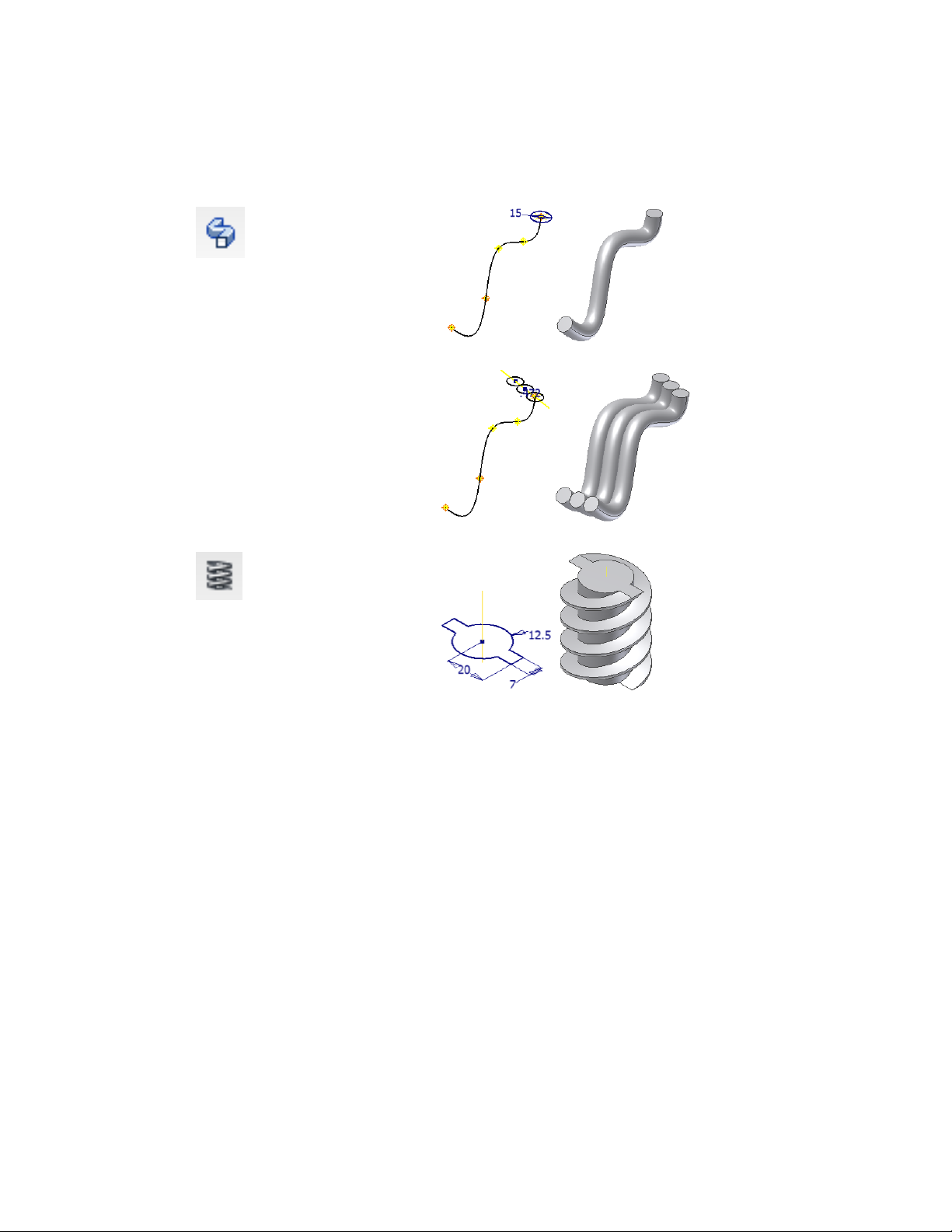
Sweep
Projects a single sketch profile along
a single sketched path.
The path can be open or closed.
A sketch profile can contain multiple
loops that reside in the same sketch.
Can create a body.
Coil
Projects a sketch profile along a helical
path.
Use Coil to create springs or to model
physical threads on a part.
Can create a body.
The models created by these operations are typically solid features or new
bodies that form a closed volume.
Surfaces
You can create surfaces with many of these operations. Surfaces can form an
open or closed volume but contain no mass. Use surfaces to define shapes,
use as a split tool, or sculpt certain aspects of the part body.
Sketched Features | 21
Page 28

The following features require sketches, but do not create a base feature because
they are dependent on existing geometry.
Rib
Creates a rib or web extrusion from a
2D sketch.
Use Rib to create thin-walled closed
support shapes (ribs) and thin-walled
open support shapes webs.
Emboss
Creates a raised (emboss) or recessed
(engrave) feature from a sketch profile.
22 | Chapter 2 Create Digital Prototypes
Page 29

Decal
Applies an image file to a part face.
Use decal to add realism or to apply a
label.
LocationFor more information
Help topic
Search:
“Plan and create sketches”
“Sketch properties”
Parts 1 - Create PartsTutorial
Sketch Environment
When you create or edit a sketch, you work in the sketch environment. The
sketch environment consists of a sketch and sketch commands. The commands
control the sketch grid and draw lines, splines, circles, ellipses, arcs, rectangles,
polygons, or points.
When you open a new part file, the sketch environment is active. The 2D
Sketch button is selected, and the Sketch commands are available, along with
a sketch plane on which to sketch. You can control the initial sketch setup
by using template files, or settings in the Application Options dialog box,
Sketch tab.
When you create a sketch, a sketch icon displays in the browser. When you
create a feature from a sketch, a feature icon displays in the browser with the
sketch icon nested under it. When you click a sketch icon in the browser, the
sketch is highlighted in the graphics window.
After you create a model from a sketch, re-enter the sketch environment to
change or start a new sketch for a new feature. In an existing part file, first
activate the sketch in the browser. This action activates the commands in the
Sketched Features | 23
Page 30

sketch environment. You can create geometry for part features. The changes
you make to a sketch are reflected in the model.
LocationFor more information
Help topic
Search:
“Sketch Environment”
“Application Options settings > Part tab”
“Application Options settings > Sketch tab”
Work with Sketch BlocksTutorial
Sketch Blocks
In many assembly designs, rigid shapes are repeated.
You can use sketch blocks to capture such shapes as a
fixed set, and place instances of the set where needed.
You can define nested sketch blocks and place flexible
instances of these blocks. These flexible instances retain
specified degrees of freedom that allow them to simulate
kinematic subassemblies.
Sketch blocks are created in 2D part sketches and can be comprised only of
sketch objects. Sketch block definitions are contained in the Blocks folder
while sketch block instances reside under the parent sketch. You can control
the appearance and format of block definitions and instances.
Use sketch blocks to represent components in your top-down design layout.
After you create a sketch block, you can add instances of the block to your
layout. This method for adding components in multiple locations in the design
is quick and associative. Any changes to the block definition are propagated
to all block instances.
LocationFor more information
Help topic
Search:
“Sketch blocks”
“Top-down design”
Sketch BlocksTutorial
24 | Chapter 2 Create Digital Prototypes
Page 31

Sketch Constraints
Constraints limit changes and define the shape of a sketch. For example, if a
line is horizontally constrained, dragging an endpoint changes the length of
the line or moves it vertically. However, the drag does not affect its slope. You
can place geometric constraints between:
■ Two objects in the same sketch.
■ A sketch and geometry projected from an existing feature or a different
sketch.
As you sketch, constraints are automatically applied to the various sketch
elements. For example, if the horizontal or vertical symbol displays when you
create a line, then the associated constraint is applied. Depending on how
accurately you sketch, one or more constraints could be required to stabilize
the sketch shape or position. You can also add constraints manually to any
sketch element.
Although you can use unconstrained sketches, fully constrained sketches result
in more predictable updates.
LocationFor more information
Search: “Constrain Sketches”Help topic
Explore Sketch ConstraintsTutorial
2D AutoCAD Data in Sketches
When you open an AutoCAD® file in Autodesk Inventor, you can place 2D
translated data:
■ On a sketch in a new or existing drawing.
■ As a title block in a new drawing.
■ As a sketched symbol in a new drawing.
■ On a sketch in a new or existing part.
You can import AutoCAD (DWG) drawings into a part sketch, drawing, or
drawing sketch overlay. The entities from the XY plane of model space are
placed on the sketch. In a drawing, certain entities, such as splines, cannot
Sketched Features | 25
Page 32

be converted. You can choose to import AutoCAD blocks as Autodesk Inventor
sketch blocks.
When you export Autodesk Inventor drawings to AutoCAD, the converter
creates an editable AutoCAD drawing. All data is placed in paper space or
model space in the DWG file. If the Autodesk Inventor drawing has multiple
sheets, each is saved as a separate DWG file. The exported entities become
AutoCAD entities, including dimensions.
You can open a .dwg file and then copy selected AutoCAD data to the clipboard
and paste into a part, assembly, or drawing sketch. The data is imported at
the cursor position.
LocationFor more information
Help topic
Placed Features
Placed features are common engineering features that do not require a sketch
when you create them with Autodesk Inventor. You usually provide only the
location and a few dimensions.
The standard placed features are shell, fillet, chamfer, face draft, hole, and
thread.
The commands for placed features are located on the Sketch and Model tabs:
Fillet Places a fillet or round on selected edges loops, and features.
Chamfer Breaks sharp edges. Removes material from an outside edge and
adds material to an inside edge.
Hole Places a specified hole in a part, optionally with thread.
Thread Creates regular and tapered external and internal threads on cylindrical
or conical faces.
Shell Produces a hollow part with a wall thickness you define.
Rectangular Pattern Creates a rectangular pattern of features.
Search:
“3D sketch environment”
“AutoCAD, using geometry in Inventor”
Circular Pattern Creates a circular pattern of features.
Mirror Feature Mirrors different type of features across a plane.
26 | Chapter 2 Create Digital Prototypes
Page 33

iFeatures
Dialog boxes define values for placed features, such as the Hole dialog box.
An iFeature is one or more features that you can save and reuse in other
designs. You can create an iFeature from any sketched feature. Features
dependent on the sketched feature are included in the iFeature. After you
create an iFeature and store it in a catalog, you can drag it from Windows
Explorer and drop it in the part file. You can also use the Insert iFeature
command.
LocationFor more information
Help topic
Assembly Features
Assembly features are like part features, except that you create them in the
assembly environment. They can affect multiple components in an assembly
file, but the modifications do not alter the included component files. If
assembly features are used, use LOD reps to exclude unnecessary components.
The more participants, the bigger the file size and the longer it takes to
calculate the feature. You usually suppress assembly features before saving.
Assembly features include chamfers, fillets, sweeps, revolved features,
extrusions, holes, move face, rectangular feature pattern, circular feature
pattern, and mirror. They also include the work features and sketches used to
create them. The workflow and dialog boxes are the same as for part features.
However, some operations are not available, such as creating a surface for
extruded and revolved features.
You can edit, add to, suppress, or delete assembly features. You can also roll
back the state of the assembly features and add or remove components that
participate in the feature.
Search:
“Placed features”
“iFeature fundamentals”
LocationFor more information
Search: “Assembly Features”Help topic
Assemble and Constrain ComponentsTutorial
iFeatures | 27
Page 34

Work Features
Work features are abstract construction geometry that you can use to create
and position new features when other geometry is insufficient. To fix position
and shape, constrain features to work features.
Work features include work planes, work axes, and work points. The proper
orientation and constraint conditions are inferred from the geometry you
select and the order in which you select it.
The work feature commands provide on-screen prompts to help you with
selection and placement. You can:
■ Create and use work features in the part, assembly, sheet metal, and 3D
sketch environments.
■ Use and refer to work features in the drawing environment.
■ Project work features into a 2D sketch.
■ Create in-line work features to help you define a 3D sketch or position a
part or assembly feature.
LocationFor more information
Show me how to create an assembly featureShowme
■ Make work features adaptive.
■ Turn the visibility of work features on or off.
■ Drag to resize work planes and work axes.
LocationFor more information
Help topics
Search:
“Adaptive work features”
“Work axes”
“Work planes”
“Work points”
Explore Sketch ConstraintsTutorial
28 | Chapter 2 Create Digital Prototypes
Page 35

Edit Features
In the browser, right-click a feature, and then use one of several options on
the menu to modify the feature:
Displays the sketch dimensions so you can edit them.Show Dimensions
■ Change the dimensions of a feature sketch.
■ Change, add, or delete constraints.
Activates the sketch so it is available for edit.Edit Sketch
■ Modify or create a new profile for the feature.
After you modify a part sketch, exit the sketch and the
part updates automatically.
Opens the dialog box for that feature.Edit Feature
■ Choose a different method to terminate the feature.
■ Choose whether the feature joins, cuts, or intersects
another feature.
3D Grips
Assemblies
Assembly modeling combines the strategies of placing existing components
in an assembly, and creating other components in place within the context
Uses grip handles to drag a feature or face, or snap to
other geometry to resize a feature. Arrows indicate the
drag direction. The feature preview shows the expected
results before you commit to the change.
LocationFor more information
Search: “Features and feature termination”Help topic
Parts 2 - Create Base PartsTutorial
Edit Features | 29
Page 36
of the assembly. In a typical modeling process, some component designs are
known and some standard components are used. Create the designs to meet
specific objectives.
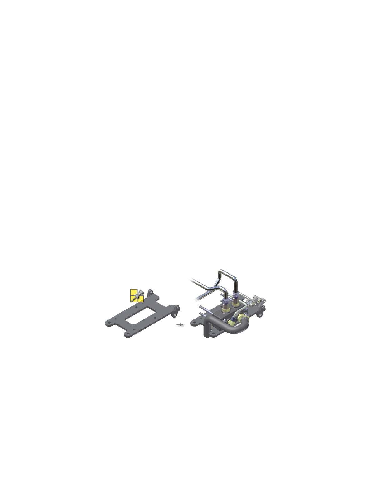
Place Components
In the assembly environment, you can add existing parts and subassemblies
to create assemblies, or you can create parts and subassemblies in-place.
A component (a part or subassembly) can be an unconsumed sketch, a part,
a surface, or any mixture of both.
When you create a component in-place, you can do one of the following:
■ Sketch on one of the assembly origin planes.
■ Click in empty space to set the sketch plane to the current camera plane.
■ Constrain a sketch to the face of an existing component.
When a component is active, the rest of the assembly is shaded in the browser
and graphics window. Only one component can be active at a time.
Choose a fundamental part or subassembly, such as a frame or base plate, to
be the first component in an assembly. Except for the first placed component,
all placed components are unconstrained and ungrounded. You add the
constraints you need.
The first component you place in an assembly is automatically grounded (all
degrees of freedom are removed). Its origin and coordinate axes are aligned
with the origin and coordinate axes of the assembly. It is a good practice to
place assembly components in the order in which they would be assembled
in manufacturing.
30 | Chapter 2 Create Digital Prototypes
Page 37

When you create a component in the assembly context, the created component
is nested under the active main assembly or subassembly in the browser. A
sketch profile for the in-place component that uses projected loops from other
components within the assembly, is associatively tied to the projecting
components.
Drag Components into Assemblies
You can place multiple components in an assembly file in a single operation
by dragging them into an open assembly window.
Drop the files over the graphics window where the assembly model is displayed.
A single occurrence of each component is placed in the assembly file. The
dropped components appear at the bottom of the browser in the receiving
assembly.
LocationFor more information
Search: “Assembly components”Help topic
Assembly Constraints
Assembly constraints establish the orientation of the components in the
assembly and simulate mechanical relationships between components. For
example, you can:
■ Mate two planes.
■ Specify that cylindrical features on two parts remain concentric.
■ Constrain a spherical face on one component to remain tangent to a planar
face on another component.
Each time you update the assembly, the assembly constraints are enforced.
Assemble and Constrain ComponentsTutorial
Assembly Constraints | 31
Page 38

Degrees of Freedom
Each unconstrained component in an assembly has six degrees of freedom
(DOF). It can move along or rotate about each of the X, Y, and Z axes. The
ability to move along X, Y, and Z axes is called translational freedom. The
ability to rotate around the axes is called rotational freedom.
Whenever you apply a constraint to a component in an assembly, you remove
one or more degrees of freedom. A component is fully constrained when all
degrees of freedom (DOF) are removed. You are not required to constrain
completely any component in an assembly in Autodesk Inventor.
To verify the DOF of components in an assembly:
■ Select Degrees of Freedom from the Visibility panel of the View tab.
■ Drag a component in the graphics window. Other components in the
assembly will move based on existing constraints.
LocationFor more information
Help topic
Search:
“Assembly Constraints Overview”
“Degrees of Freedom in Assemblies”
“Plan Constraints”
Assemble and Constrain ComponentsTutorial
32 | Chapter 2 Create Digital Prototypes
Page 39
Top-down Design
Once you are satisfied with the state of your layout, you make components
from the sketch blocks. This process, also known as push-derive, results in
part and assembly files that are associated to the layout sketch blocks. When
you change the sketch block definitions, your component files automatically
reflect the changes.
Experiment with top-down design to experience the power of truly associative
designs.
The top-down design technique (also known
as skeletal modeling) centralizes control of your
design. The technique enables you to update
your design efficiently and with minimal disruption to your design documents.
Top-down design begins with the layout. The
layout is a 2D part sketch that is the root document of your design. You create a layout that
represents your assembly, subassembly, floor
plan, or equivalent. In the layout, you use 2D
sketch geometry and sketch blocks to represent
the design components. You position these
components, in the layout, to evaluate design
feasibility.
LocationFor more information
Search: “Top-down design”Help topics
Top-down WorkflowTutorial
Create Subassemblies In-place
In the assembly environment, you can add existing parts and subassemblies
to create assemblies or you can create new parts and subassemblies in-place.
A component (a part or subassembly) can be an unconsumed sketch, a part,
a surface, or any mixture of both.
Top-down Design | 33
Page 40

When you create a component in-place, you can do one of the following:
■ Sketch on one of the assembly origin planes.
■ Click in empty space to set the sketch plane to the current camera plane.
■ Constrain a sketch to the face of an existing component.
When you create a subassembly in place, you define an empty group of
components. The new subassembly automatically becomes the active assembly,
and you can start to populate it with placed and in-place components. When
you reactivate the parent assembly, the subassembly is treated as a single unit
in the parent assembly.
Optionally, you can select components at the same assembly level in the
browser, right-click, and then select Component ➤ Demote to place them
into a new subassembly. You are asked to specify a new file name, template,
location, and default bill of materials structure. You can then move
components between assembly levels by dragging components in the browser.
Subassemblies can be nested many layers deep in a large assembly. By planning
and building subassemblies, you can efficiently manage the construction of
large assemblies. You can create subassemblies that match the intended
manufacturing scheme to facilitate the creation of your assembly
documentation.
LocationFor more information
Search: “Top-down, bottom-up, middle-out design”Help
Design Assemblies and ConstraintsTutorial
AssembliesSkill Builders
Design Accelerator Components
Design Accelerator provides a set of generators and calculators to create
mechanically correct components automatically from simple or detailed
mechanical attributes you enter.
34 | Chapter 2 Create Digital Prototypes
Page 41

You insert components using Design Accelerator generators and calculators
in the assembly environment. The generators and calculators are grouped
according to functional areas. For example, all welds are together.
For more information
Search: “Design Accelerator”Help topic
Tutorials
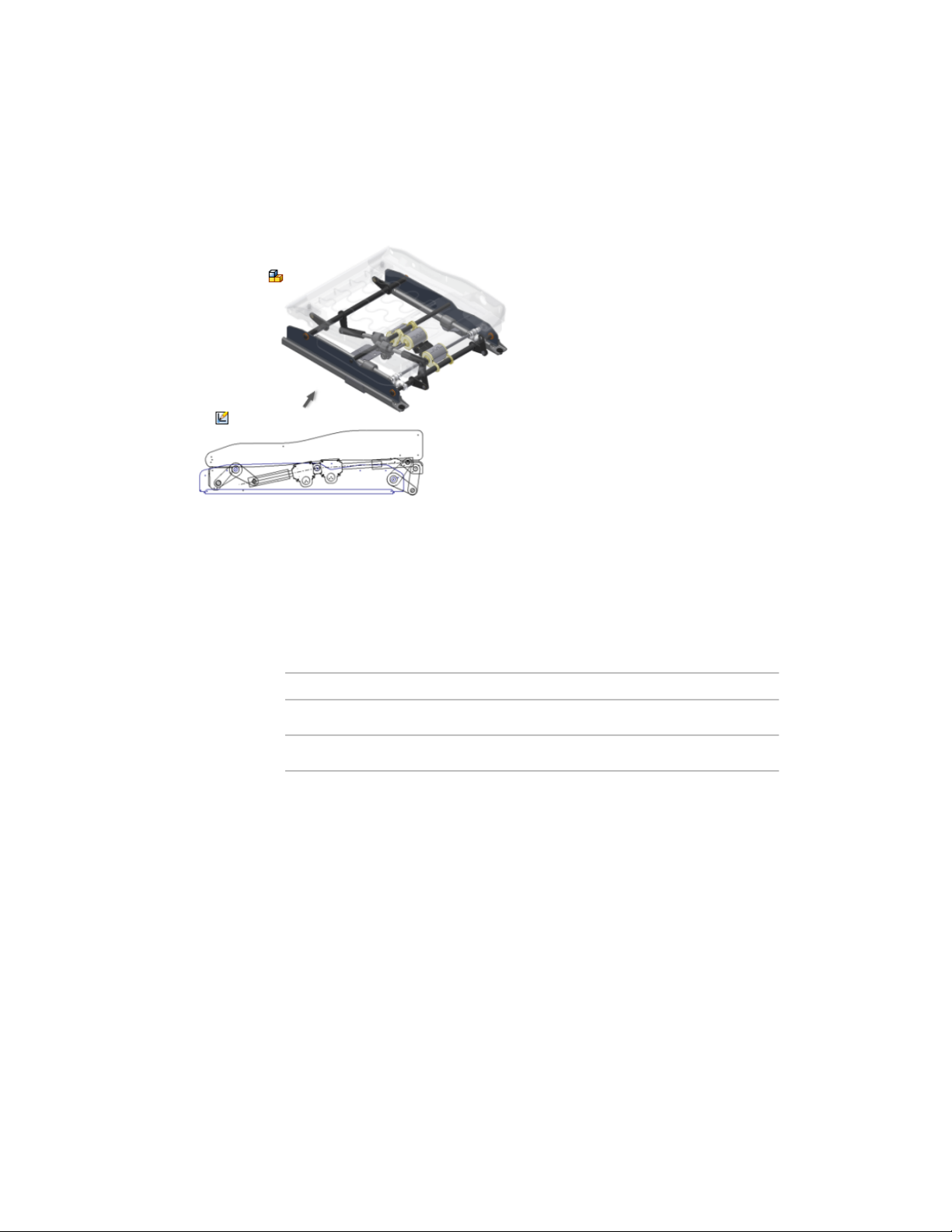
Design Mechanisms
A mechanism is defined as a design with one or more moving parts. Inventor
provides numerous tools to assist you in creating and evaluating a mechanical
design.
Use sketch blocks in a 2D part sketch to create a schematic layout of your
mechanism. Create flexible, nested blocks and apply sketch constraints to
define subassembly kinematics. Derive sketch blocks into component files
and create other features to develop your 3D models. The components remain
associated to their corresponding blocks and update to reflect any changes in
block shape.
Use the following tools to evaluate a mechanism in the 3D environment:
■ Animate an assembly constraint and enable collision detection to determine
the exact point of contact. For example, animate an angular constraint to
evaluate the range of motion before contact occurs.
Design Bolted Connections, Shafts, Spur Gears Connections,
Bearings, V-belts Connections, Disc Cams, Compression
Springs
Design AcceleratorSkill Builder
Design Mechanisms | 35
Page 42

■ Create a Contact Set and add members as required to simulate physical
contact between components and to determine the range of motion.
■ Use Positional representations to save a mechanism in various states such
as maximum and minimum extension.
■ Use Inventor Studio to animate simultaneous or sequential movement.
36 | Chapter 2 Create Digital Prototypes
Page 43

■ Use the Dynamic Simulation Environment to calculate displacements,
velocities, accelerations, and reaction forces without the cost of a physical
prototype.
■ Use the Stress Analysis Environment to conduct structural static and modal
stress analysis studies on the digital prototype.
LocationFor more information
Search: “Physical environment”Help topic
Tutorial
Check for Interference
In the physical product built from your design, two or more components
cannot occupy the same space at the same time unless they are specifically
designed to do so. To check for such errors, Autodesk Inventor can analyze
assemblies for interference.
The Analyze Interference command checks for interference between sets of
components or among the components in a single set. If interference exists,
Autodesk Inventor displays it as a solid and displays a dialog box that contains
the volume and centroid of each interference. You can then modify or move
the components to eliminate the interference.
Animate Assemblies
Explore Part Stress Analysis
Explore Assembly Simulation
LocationFor more information
Search: “Check for interference between components”Help topic
Optimize AssembliesTutorial
Check for Interference | 37
Page 44

iAssemblies
An iAssembly is a configuration of a model with a few or many variations
called members. Each member has a set of unique identifiers, such as diameter
or length. A member could have different components, such as a power train
for a vehicle with several different engine sizes.
Create an iAssembly if you want to show different quantities for assembly
components in a parts list. You can define the required parts list quantity for
each iAssembly member.
You can manage iAssemblies from a table. In an iAssembly, you can replace
one member with another member from the same factory by selecting a
different row in the table. The bill of materials and parts list automatically
update when you edit members.
LocationFor more information
Search: “iAssemblies”Help topic
38 | Chapter 2 Create Digital Prototypes
Page 45

Document and Publish Designs
During the process of creating digital prototypes in Inventor, there is often a need to
communicate the design to individuals outside the design team. In Autodesk Inventor®, you
can create the appropriate type of documentation for any consumer, such as customers or
manufacturers. The document types available are:
■ 2D drawings
■ 3D CAD files
■ Read-only files, such as DWF or PDF
■ Photo realistic renderings
You can create the documentation at any stage during the process of creating digital prototypes.
3
Drawings
A drawing consists of one or more sheets that each contain one or more 2D
drawing views and annotations. Drawings are associative to the digital
prototypes. Any change to the model is automatically reflected in the drawing
the next time you open it. You can create a drawing at any point in the design
process, and it always reflects the current state of the digital prototype.
Annotations can include dimensions, symbols, tables, and text.
Start Drawings
Drawings are created from a drawing template file. Autodesk Inventor includes
standard templates (.idw, .dwg) stored in the Autodesk\Inventor (version
39
Page 46

number)\Templates folder. The available templates are presented in the tabs
of the New File dialog box.
Drawing templates can contain sheet formats, borders, title blocks, and
sketched symbols. Templates also control the default styles and standards used
for the appearance of views and annotations.
When you start a drawing, the title block, border, sheet size, and other elements
come from the template.
Inventor Drawing Tips:
■ The template you select to create a drawing file determines the default
sheet size, title block, border, and so on. You can change the sheet size,
title block, and border after you create the drawing. The template controls
the default styles and standards used for the appearance of views and
annotations.
■ You can create customized templates and save them in the Templates folder.
To set up a drawing template, open a template file from Autodesk\Inventor
(version number)\Templates. Make your changes, and save the file with a
new name in the Templates folder. The new template is available the next
time the New File dialog box displays.
■ You can create different templates for the different sheets sizes you use,
or create multiple sheet formats in a single template.
■ To customize a drawing sheet in a template, change the default sheet size
and specify sheet orientation. Then modify the border and title blocks to
fit the sheet. Available borders and title blocks are listed in the Drawing
Resources folder in the browser.
LocationFor more information
Help topics
Search:
“Drawing Environment”
“Templates for drawings”
“Create drawings”
Prepare Final DrawingsTutorial
Types of Drawing Files
Autodesk Inventor supports IDW and DWG file types for drawings. Both file
types produce identical drawings. IDW files are the native Inventor format.
40 | Chapter 3 Document and Publish Designs
Page 47

You can open them only in Inventor or Inventor View. This file type results
in smaller file sizes.
The DWG file type is native to AutoCAD®. You can open DWG files in
AutoCAD, Inventor, or DWG TrueView. If you create data using Inventor in
a DWG file, you can modify the data only with Inventor. If you create data
using AutoCAD in a DWG file, you can modify the data only with AutoCAD.
If a downstream consumer of your Inventor data needs a DWG file, consider
using DWG files as the default in Inventor.
LocationFor more information
Help topics
Create Views of Models
A drawing view is a 2D representation of a 3D digital prototype that is placed
on a drawing sheet. The commands for views in Inventor are like view types
in drafting. The two types of view commands in Inventor are author and
modify. Author commands create new views. They are located in the Author
panel of the ribbon. Modify commands change existing views. They are located
on the Modify panel of the ribbon.
The first view placed on a drawing is a base view. Subsequent views are either
children of the base view or additional base views. As you create views, they
are listed in the browser with the sheet, title block, and border.
Types of Drawing Views
Base View
The first view created in a drawing. The base view is the source for
subsequent views and controls the scale and alignment for them.
You can create one or more base views on a drawing sheet.
You select the orientation of the view when you create it. The default
orientations are based on the origin in the digital prototype.
Search:
“Create drawing templates”
“DWG Translation”
Create Views of Models | 41
Page 48

Projected View
An orthographic or isometric view that is generated from a base view
or other existing view. You can create multiple projected views in a
single operation. The position of the cursor relative to the parent view
determines the orientation of the projected view.
Projected views inherit the scale and display settings from the parent
view. Orthographic projected views keep alignment with the parent
view. The active drafting standard defines the first-angle or third-angle
projection.
Auxiliary View
A view projected perpendicular to a user-selected line or edge. Use
Auxiliary View to document features on inclined faces.
The position of the cursor relative to the parent view determines the
orientation of the auxiliary view. Auxiliary views inherit the scale and
display settings from the parent view.
Section View
A view created by sketching a line that defines a plane used to cut
through a part or assembly. You draw the cutting line when you
create the view, or select it from a sketch associated to the parent
view. The cutting line can be a single straight segment or multiple
segments. The cutting line arrowheads on the base view automatically
orient to reflect the position of the section view relative to the base
view.
The crosshatching, section line, and labels are placed automatically.
Detail View
An enlarged view of a specified portion of another drawing view. By
default, the scale of the detail view is double the scale of the parent
view, but you can specify any scale. A detail view is created without
alignment to its parent view.
Autodesk Inventor labels the detail view and the area it is derived
from on its parent view. You can set either a circular or rectangular
fence for the detail.
42 | Chapter 3 Document and Publish Designs
Page 49

Overlay View
A single view that shows an assembly in multiple positions. Overlays
are available for base, projected, and auxiliary views. The overlay view
is created on top of the parent view.
Draft View
A view created from a 2D sketch in the drawing file. You can place a
draft view and construct a drawing without an associated model. A
draft view can provide detail that is missing in a model.
Drawing View Operations
Break
An operation that reduces the size of a model by removing or
“breaking” irrelevant portions. Create a break in a view if the component view exceeds the length of the drawing, or contains large
areas of nondescript geometry. An example is the center portion of
a shaft.
Dimensions that span the break reflect the true length.
Break Out
An operation that removes a defined area of material to expose obscured parts or features in an existing drawing view. The parent view
must have an associated sketch that contains the profile defining the
break out boundary.
Create Views of Models | 43
Page 50
Crop
An operation that provides control over the view boundary in an existing drawing view. The clipping boundary can be a rectangle or
circle you create during the command, or a closed profile you select
from a sketch.
Slice
An operation that produces a zero-depth section from an existing
drawing view. You perform the Slice operation in a selected target
view. The slice lines are defined in a sketch associated to a different
view.
Drawing View Tips
■ You can edit views placed in drawings to change settings such as scale,
hidden line display, thread display, and so on. If the edited view is a parent
view, changes to the view parameters are reflected in dependent views.
■ You can remove the association between a parent and a dependent view
by editing the dependent view. Then you can set independent scale, style,
and alignment for the dependent view.
■ You can move a view by clicking and dragging the red border. You can
move multiple views with a crossing selection window.
■ Most dependent views are created with an alignment (vertical, horizontal,
in position) to the parent. An aligned view can be moved only within its
constraints. If the parent view is moved, the aligned view moves to
maintain its alignment. You can manually break the alignment between
the child and parent view.
■ You can delete views that are no longer needed. If you delete a base view,
dependent projected and auxiliary views can be deleted or retained. Section
and detail views require a parent view and cannot be retained.
44 | Chapter 3 Document and Publish Designs
Page 51

■ You can suppress views so that they do not display on the drawing sheet.
Suppressed views are useful when one view is created only for creating a
child view. The suppressed view can still be accessed in the browser.
Exploded Views
LocationFor more information
Search: “Drawing views”Help topic
Prepare Final DrawingsTutorial
DrawingsSkill Builders
Exploded views are commonly used to describe assemblies by moving
components out from their assembled position. Exploded views are
often used to balloon an assembly using item numbers found in a
parts list or bill of material. Exploded views are created by using a
combination of assembly (.iam), presentation (.ipn), and drawing
(.idw, .dwg) files. A view of the assembly is created in the presentation
file and the components are repositioned in the view. Drawing views
are then generated from the presentation file.
Annotate Drawing Views
Drawing annotations provide additional information to drawing views to
complete documentation of a digital prototype. The styles that correspond to
the active drawing standard determine the appearance of drawing annotations.
Drawing annotations are linked to model geometry and update accordingly
with model changes. Once annotations are placed on the sheet, they can be
moved using grips.
LocationFor more information
Search: “Exploded views and presentations”Help topic
Create Exploded ViewsTutorial
Exploded Views | 45
Page 52

Types of Drawing Annotations
General Dimensions
You can create general dimensions in orthographic or isometric views.
The geometry you select determines the dimension type and the
options available in the right-click menu.
You can override the dimension text, which does not affect the
model geometry.
You can change the dimension precision and tolerance, edit the
leader and arrowheads, or modify the content of dimension text.
Baseline Dimensions and Baseline Dimension Sets
Creates multiple dimensions that display the orthogonal distance
between the origin (base line) and selected edges or points. The first
edge or point selected is the origin geometry. You can create individual dimensions or a dimension set.
Ordinate Dimensions and Ordinate Dimension Set
Creates multiple ordinate dimensions in a single process. Ordinate
dimensions automatically align as you place them. If dimension text
overlaps, you can modify the dimension position or dimension style.
You can create individual dimensions or a dimension set.
Retrieve Dimensions
Displays all model dimensions, or only dimensions related to selected
parts or features. You select the dimensions to maintain in the drawing
view.
Only model dimensions parallel to the view plane are available.
Model dimensions can be modified to manipulate the part file.
46 | Chapter 3 Document and Publish Designs
Page 53

Center Marks
Center marks are added to the selected arc or circle. Center mark
extension lines are automatically sized to fit the geometry.
Center marks can be added individually or using the automated
centerlines command.
Centerlines
Creates centerlines for selected edges, at the midpoint for lines, or
at the center point of arcs or circles. Creates a circular centerline when
features form a circular pattern.
Autodesk Inventor supports three types of centerlines: bisector,
centered pattern, and axial.
Hole/Thread Notes
Hole or thread notes display the information from hole, thread, and
cylindrical cut extrusion features on a model. The style of the hole
note varies depending on the type of feature selected.
Chamfer Notes
Chamfer notes contain distance and angle measurements for selected
model edges or sketched lines.
You can attach chamfer notes to angled edges in views and sketches.
A chamfer edge and reference edge from different bodies, models,
or sketches, must be part of the same view.
Symbols
Various types of symbols are available: Surface texture, welding, feature control frame, feature identifier, datum target, and datum identifier symbols. Symbols are created with or without a leader.
Annotate Drawing Views | 47
Page 54

User-defined or sketched symbols are defined in the Drawing Resources and are placed like standard symbols. They are used to define
custom symbols that are not available in Autodesk Inventor.
Bend Notes
A bend not adds fabricating information to sheet metal bend, contour
roll, and cosmetic centerlines. Bend notes can be added to flat pattern
views of sheet metal parts.
A bend note is associated with the selected bend centerline. The default placement of the bend note is above the selected bend centerline. It constrains the bend text to the midpoint of the centerline and
offsets by the Origin Offset value from the Dimension Style.
Punch Notes
A punch note includes data related to the punch feature: for example
the punch ID, angle, direction, depth, quantity note, and so on.
Punch notes can be added to flat pattern views of sheet metal parts.
Caterpillars
Weld caterpillars are used to denote weld features in 2D views. You
can add weld caterpillars manually using the Caterpillar command.
Add them automatically from weld features using Get Model Annotations > Get Weld Annotations on the right-click menu.
End Fills
End fills are used to represent the filled region indicating the end of
a weld bead. You can add them manually using the End Fill command
or automatically from weldment models using Get Model Annotations
> Get Weld Annotations.
Change end fill appearance through object properties.
48 | Chapter 3 Document and Publish Designs
Page 55

Balloons
Balloons are annotation tags that identify items listed in a parts list.
Balloons can be placed individually or automatically for all components
in a drawing view. You can add balloons to a custom part after it is
added to the parts list.
The balloon shape and value can be overridden using Edit Balloon
on the right-click menu. You can combine balloons to use a single
leader using the attach balloon options on the right-click menu.
Parts lists
Parts lists display data saved in the assembly bill of materials. The
parts list can be modified to include different columns or overriden
values. The bill of material data can be modified from the drawing
file or the assembly file.
Custom parts can be added to the parts list to include items that are
not modeled such as paint or grease.
Tables
You can create a general, configuration, or bend table.
A general table can have a default number of rows and columns, or
you can customize its size. The general table can reference external
data from .xls, .xlsx, or .csv files, or you can enter any other type of
data you need.
In drawings of iParts and iAssemblies, configuration table rows represent the members of the factory. You can specify the columns to include in the configuration table, such as exclusion status and values
that are different among members.
A bend table is created if a sheet metal part is the source of the table.
Bend tables contain bend information such as angle and radius.
Hole Tables
Hole tables show the size and location of the hole features in a model.
When a hole table is added, each individual hole receives a hole tag
and a corresponding row is added to the table.
You can also add center marks, punch features, and cylindrical cut
extrusion to a hole table by editing the table.
Annotate Drawing Views | 49
Page 56

Revision Tables and Tags
Revision tables include information about design changes. Revision
tables can be created for the entire drawing file or a single sheet.
A revision tag marks an object changed by design revisions. The default revision level for the tag is the latest revision in the table. The
revision level of the tag can be changed using the right-click menu.
Text or Leader Text
Use the Text command to add general notes to a drawing. General
notes are not attached to any view, symbol, or other object in the
drawing.
Use the Leader Text command to add notes to objects in a drawing.
If you attach the leader line to geometry in a view, the note is moved
or deleted when the view is moved or deleted.
LocationFor more information
Search “Drawing Annotations”Help topic
Prepare Final DrawingsTutorial
Skill Builder
Drawings:
Sketched Symbols: Stacking
Parts List - Add a Custom Part
Styles and Standards
Inventor uses styles and standards to control the formats of views and
annotation objects. The formats include dimension appearance, layers,
linetypes, text styles, table formatting, and any other formatting related to
annotation objects. Style and standard information is contained in a style
library that is referenced by all documents. When you install Autodesk
Inventor, you specify a default drafting standard which contains a set of styles.
You can install and configure multiple standards and styles.
Styles and standards tips:
■ You can customize existing styles or create new styles. Copy an existing
style, and make the desired changes to create a style. The style changes are
saved in the current document and are not available to other documents
until you save them to the style library.
50 | Chapter 3 Document and Publish Designs
Page 57

■ You can store all or some of the style information in a drawing file or
template instead of using the styles library. This method is useful when
you make one-time overrides that you do not want to affect all drawings.
■ If a style is stored in a template, it is available only to future documents
created with the template. Update manually the documents you created
previously. With style libraries, a style definition is available in any
document simply by refreshing the library.
■ Use the Object Defaults list to map drawing annotation objects to styles
and drawing layers.
■ Link a customized style library to a project file (.ipj) to share styles among
designers. All files included in the project then use the same styles for
formatting. Documents are uniformly formatted, and updates are easy.
When you update the main style definition in the library, all documents
that use the style library can update their formatting.
LocationFor more information
Help topic
Skill Builders
Search:
“Styles in drawings”
“Configure the company standard styles using the Styles
Editor”
Drawings:
Drawing Styles - Objects
Studio in Autodesk Inventor
Studio in Autodesk Inventor | 51
Page 58

Inventor Studio is a rendering and animation environment within Part and
Assembly documents. You can produce both illustrative and realistic imagery
of your part or assembly.
Inventor Studio images can be used to document products, present concepts
to investors, clients, or your management team. The images you create can
be used in a wide variety of places within the corporate environment. In
addition, you can provide animations of how your design works. And, even
better, with Video Producer (part of Studio) you are able to compose shots
from multiple cameras and produce a more cinematic animation video.
As an environment within part and assembly documents, you simply choose
when you want to enter the environment and do so. You can render an image
using one of the standard lighting and scene styles or make new ones to suit
your needs. You can save and share your custom lights, colors, and scene styles
with others in your design community. Animations use the existing assembly
constraints. All you do is specify a time period and what the intended end
condition of the constraint is. A timeline provides easy access to adjusting the
timing of each animated object.
Animating positional representations existing deep within the assembly
requires extra time and effort. We recommend that you become familiar with
Inventor Studio and the various representation options before you immerse
yourself in this area.
Find out more within the Help content, books about Inventor, online resources
of other Inventor users, and the Autodesk Newsgroup at
http://discussion.autodesk.com.
LocationFor more information
Search: “Render and animate with Inventor Studio”Help topic
Render Models with StudioTutorial
Animate Assemblies
Create Positional Representations
Studio:Skill Builders
Animate Camera
Advanced Camera Animation
52 | Chapter 3 Document and Publish Designs
Page 59

Publish Designs
Digital prototype data can be published to various formats in Inventor. This
data can include parts, assemblies, drawings, or a combination of these
depending on the file type selected. To publish, use the Save Copy As command
and select a file type, or use the various Export commands. Supported file
types include:
■ 2D and 3D DWF files
■ CAD file formats including Parasolid
■ 2D PDF files
■ Image files including BMP, JPEG, PNG, or TIFF
DWF files are an Autodesk file type that can contain 3D data, 2D data, and
bill of materials information. You can view DWF files in Autodesk® Design
Review, a free download that contains tools to view, print, and mark up DWF
files.
®
, Pro/ENGINEER®, and STEP
LocationFor more information
Help topic
Web links
Search:
“Publishing 3D data”
“Publishing 2D data”
“Publish to DWF”
“DWF markup”
“Export parts, assemblies, and more”
autodesk.com/designreview
dwfcommunity.autodesk.com
autodesk.com/dwfwriter-download
Publish Designs | 53
Page 60

54
Page 61

Manage Data
4
Autodesk Inventor® provides various means to share files within your internal workgroups,
and with team members outside your organization. You can import and export files from and
into other CAD software, and you can share Inventor files with team members who do not
use CAD software.
Share Files in Work Groups Using Vault
Autodesk® Vault is a work group data management system for sharing design
data across a project team. The vault provides a file management and version
control system for all engineering and related data. It provides design team
members with a central and secure collaborative environment.
Autodesk Vault in a shared environment consists of two components: the Vault
server and vault clients. The server stores the master data files of all design
information. The clients provide access to the files stored on the server.
55
Page 62

Design teams use Autodesk Vault for version control and to store and share
all types of engineering files and related data. Files can be Autodesk Inventor,
AutoCAD®, Autodesk® DWF™ (Design Web Format), FEA, CAM, or Microsoft
Office. They can be any other file used in the design process.
All versions of files that are checked into the vault are retained, along with
any file dependencies, providing a living history of the project. Team members
have access to the files and data stored on the server, and the history of files.
They check out files to prevent more than one member from editing the same
file at the same time. After a file is checked back into the vault, team members
can refresh their local copies.
Autodesk Vault Add-ins for Design Applications
Add-in clients provide basic vault functions within the environment of a
parent application, such as AutoCAD and Autodesk Inventor. Add-ins maintain
application-specific data relationships when adding files to a vault.
There are add-ins available for Autodesk® and non-Autodesk design
applications.
NOTE If an integrated client is available for a particular application, managing
files using that client minimizes loss of data, like assembly relationships. We
recommend that you use integrated clients whenever possible.
®
56 | Chapter 4 Manage Data
Page 63

Microsoft Office Add-ins
The Microsoft Office Add-in performs basic vault functions on documents,
spreadsheets, and other non-CAD data within any of these Microsoft Office
applications: Word, Excel®, and PowerPoint®.
Copy Designs Using Vault
The Copy Design function in Autodesk Vault copies an Inventor design with
all related files to create another design. Use Copy Design to copy an entire
assembly structure, including all related 2D drawings and 3D models, to derive
a new design. Copy Design preserves the relationships and can eliminate hours
of rework. For example, an existing part and the related drawing file are copied
and assigned new names. The new part and drawing are fully associative to
each other. The dimensions and view layout from the original source document
is preserved in the new drawing.
In the Copy Design dialog box, you can choose which parts of an existing
design to copy, reuse, exclude, or replace. You can define a naming scheme
for the files you copy to the new design. Alternatively, you can choose to add
a prefix and a suffix to the file names automatically. If the original file names
end in an integer, you can choose to automatically increment the names. You
can rename presentation files and drawing files to match the names of their
direct part or assembly source.
LocationFor more information
Help topics
Search:
“Learn about Autodesk Vault”
“The Autodesk Vault Environment”
“Tutorial: Performing Vault tasks in Autodesk Inventor”
“Getting Started with the Autodesk Vault Add-in”
“Autodesk Inventor and the Vault”
Share Files Externally
Team members outside your organization can access designs using Autodesk
Productstream and Autodesk Design Review software. They can review and
manage data throughout the design and manufacturing processes.
Microsoft Office Add-ins | 57
Page 64

Autodesk Vault Manufacturing
Vault Manufacturing is a product data management (PDM) application that
provides a modular and practical approach to controlling your design data.
It bridges the gap between CAD data and the manufacturing process. You can:
■ Track the life cycle of designs and materials used to manufacture a product.
■ Manage what you make, buy, assemble, and deliver to customers.
Vault Manufacturing automates the process of tracking and managing the
engineering release process. Items are managed through various working states
such as work-in-progress, released, and obsolete. Bills of material (BOMs)
coordinate the items in a total parts list. Change orders are submitted, reviewed,
approved, and tracked through the routing process using Vault Manufacturing.
Vault Manufacturing Web Client is the Web browser-based application that
gives access to the vault and its data to groups outside the engineering
department. They can:
■ Access all items and files in the Web Client, including released revisions.
■ View, and print details of items and files in the Web Client.
LocationFor more information
The separate Help in the Vault Manufacturing product.Vault Manufacturing Help
Autodesk Design Review
Using the free Autodesk Design Review software, team members who do not
use CAD can access designs. They can review, mark up, measure, and track
changes to designs and drawings. The markups and their statuses are saved
in the DWF file.
58 | Chapter 4 Manage Data
Search: “Installation and Deployment”Help topic
LocationFor more information
Design Review Help.Autodesk Design Review software
Search: “DWF markup”Help topic
Page 65

LocationFor more information
Web links
Import and Export Data
To translate files, you open or import the files in Autodesk Inventor. You can
also place part and assembly files as components in Autodesk Inventor
assemblies and drag and drop part and assembly files into Autodesk Inventor.
In the open, import, and place components workflows, you can choose from
specific import options to achieve the intended results. The import options
are available when you select a file and click Options on the dialog box. Details
of the import operation are contained in the translation report, under the
corresponding third-party browser node.
AutoCAD Files
When you open an AutoCAD file in Autodesk Inventor, you can select the
AutoCAD data to translate:
■ Model space, a single layout in paper space, or 3D solids.
■ One or more layers.
autodesk.com/designreview
dwfcommunity.autodesk.com
You can also place 2D translated data:
■ On a sketch in a new or existing drawing.
■ As a title block in a new drawing.
■ As a sketched symbol in a new drawing.
■ On a sketch in a new or existing part.
If you translate 3D solids, each solid becomes a part file containing an ASM
solid body. Blocks are translated as sketched symbols.
You can import AutoCAD (DWG) drawings into a part sketch, a drawing, or
a drawing sketch overlay. The converter takes the entities from the XY plane
of model space and places them on the sketch. In drawings, you cannot convert
certain entities, such as splines. You can choose to import AutoCAD blocks
as Autodesk Inventor sketch blocks.
Import and Export Data | 59
Page 66

You can export Autodesk Inventor drawings to AutoCAD. The converter creates
an editable AutoCAD drawing and places all data in paper space or model
space in the DWG file. If the Autodesk Inventor drawing has multiple sheets,
each is saved as a separate DWG file. The exported entities become AutoCAD
entities, including dimensions.
You can open a DWG file and then copy selected AutoCAD data to the
clipboard and paste into a part, assembly, or drawing sketch. The data is
imported at the cursor position.
The options for importing and saving AutoCAD® files in Autodesk Inventor
are:
■ Selection of layers.
■ Window selection of entities.
■ Saving files in DWG format.
■ Support for DXF files back to version 12.
■ Creation of AutoCAD
®
Mechanical files, if AutoCAD Mechanical is installed.
NOTE Mechanical Desktop files can be linked to Autodesk Inventor assemblies
without importing.
LocationFor more information
Help topics
60 | Chapter 4 Manage Data
Search:
“DWG Translation”
“Use your AutoCAD geometry”
“Export drawing data to AutoCAD”
Page 67

Import Files from Other CAD Systems
You can import part and assembly files from other
CAD systems. The import operation does not
maintain associativity with the original file, except
when you associatively import Alias files. After you
import the files, you can treat them as if they were
originally created in Autodesk Inventor. You can
import these files:
■ Alias
■ CATIA V5
■ JT
■ Pro/ENGINEER
■ Parasolid
■ SolidWorks
■ UGS NX
You can also import SAT, STEP, IGES, and Mechanical Desktop (DWG) files.
LocationFor more information
®
™
®
Help topics
Search:
“Parts and assemblies from other CAD systems”
”Import and use IGES data”
“Import and use STEP data”
Import Files from Other CAD Systems | 61
Page 68
Export Files to Other CAD System Formats
You can export Autodesk Inventor parts, assemblies, and more to other CAD system formats.
The export operation does not maintain associativity with the original Autodesk Inventor file.
You can export these files:
■ CATIA V5
■ JT
■ Pro/ENGINEER
■ Parasolid
You can also export to SAT, STEP, IGES, DWF,
and various graphic files formats.
LocationFor more information
®
®
Help topics
62 | Chapter 4 Manage Data
Search:
“Export parts, assemblies, and more”
“Save, Save As, Export”
“DWF markup”
Page 69

Set Your Environment
5
The basics in this manual get you started using the Autodesk Inventor® software. References
in For More Information tables throughout the manual guide you to Help topics, tutorials,
and other resources that contain detailed information and specific instructions.
Find out more within books about Autodesk Inventor, online resources of other Autodesk
Inventor users, and the Autodesk® Newsgroup at http://discussion.autodesk.com.
Along with the procedures in Help, the tutorials provide the step-by-step procedures that
complement the information in this manual.
When you launch Autodesk Inventor, and before you open a file, the Get Started tab displays
in the ribbon. The Get Started tab provides access to the many learning resources and customer
involvement opportunities.
Commands and Tools
The Quick Access Toolbar (QAT) at the top of the screen is a set of common
commands you can access across all environments. You can add commands to
the QAT. Then, if necessary to accommodate numerous commands, you can
dock the QAT under the ribbon.
The commands and tools for modeling are located on the ribbon below the
QAT, organized by tab and by panels on each tab. The panel display on each
tab is context dependent. In certain situations, a panel can be hidden. To check
for hidden panels, right-click in the ribbon next to the panels. A list of the
panels displays. Panels with no check marks are hidden. Select to add the check
mark and display the hidden panel.
This illustration shows some of the panels on the Sketch tab.
63
Page 70

The arrows on some of the commands and panel name bars reveal more
options.
The display of commands on the ribbon changes as you open and work in
different types of files. Commands that are not accessible are shown as shaded,
and you cannot select them.
Purpose or task drives the environments within Autodesk Inventor. The
components of each environment are consistent in their placement and
organization, including points of access for entry and exit. Unique colors
identify tabs specific to a specialized environment so you can recognize the
environment as you work.
To collapse the ribbon to the Panel name level, or to collapse it entirely, click
the arrow to the right of the tab names.
When you start a file, the ribbon is docked at the top of the screen immediately
below the QAT. View the video available in Help to see how to manipulate
and customize the display of the ribbon.
LocationFor more information
Help topics
Ribbon ➤ Get Started tab
64 | Chapter 5 Set Your Environment
Search:
“Customize work environments in Autodesk Inventor”
“View commands”
“Custom command aliases”
“Application Options settings”
Ribbon Introduction
Ribbon Tutorial
Command Locator
Getting Started Guide
Tutorials
Show Me Animations
Page 71

Environment Preferences
The options you select on the Application Options and Document Settings
dialog boxes control the display of the environment. Access to the dialog
boxes is on the Tools tab, Options panel.
Application Options
The settings in the Application Options dialog box control the look and feel
of Autodesk Inventor. Various tabs control the color of your display, the
behavior and settings of files, the default file locations, and various
multiple-user functions.
Application options remain in effect until you change them.
Access to Application Options is available at the bottom of the Applications
menu under Options.
Document Settings
The Document Settings dialog box controls the settings in individual files.
Various tabs control settings for the active document. You can specify the
active styles, units of measure, sketch and modeling preferences, bill of
materials, and default tolerance.
tion
Help topics
LocationFor more informa-
Search:
“Customize work environments in Autodesk Inventor”
“Application Options settings”
Styles and Standards
The Style and Standard Editor provides options where you set your preferences
for styles and standards. Access to the Style and Standard Editor is on the
Manage tab, Styles and Standards panel.
You select a drafting standard when you install Autodesk Inventor. The default
set of styles in standards control most objects used in documents, such as
balloons, dimensions, text, tables, and so on. The default styles are usually
Environment Preferences | 65
Page 72

enough to get you started. Use the Style and Standard Editor to customize
styles.
By default, actions such as creating or modifying styles affect only the current
document. You can choose to save the style to the style library, a master library
that contains definitions for all available styles associated with a drafting
standard. Usually, a CAD administrator manages the style library. This practice
ensures that no one replaces by accident the style definitions, used by all
documents that use the drafting standard, with a custom style.
Style Libraries
Style libraries make it easy to share formatting conventions across projects
because they contain the definitions of formatting objects. You can use a style
library to update a style for all documents. For instance, you can revise the
arrow heads of dimensions by editing the style and saving the revision to the
master style library. All documents that use that drafting standard have access
to the library and any new or changed styles that are added to it.
LocationFor more information
Help topics
Styles
Views of Models
The View tab contains commands for viewing models.
Search
“Work with styles”
“Styles in drawings”
Tutorials link from Help home page.Tutorial - Use Sheet Metal
66 | Chapter 5 Set Your Environment
Page 73

When ViewCube and NavBar are selected,
they display in the upper right corner of
the graphics window.
The NavBar contains the basic view commands.
LocationFor more information
Help topics
Templates
Once you activate Autodesk Inventor, you can open an existing file or start a
new file. Templates are available on the Application menu under New. You
can choose from several templates with predefined units. Use the tabs to select
your standard.
Search:
“Overview of the ViewCube”
“Navigation Tools”
“Views of models”
Templates | 67
Page 74

Templates are stored in the following directories in the English or Metric
subdirectories.
Projects
■ Windows
■ Windows Vista
®
XP: Autodesk\Inventor(version number)\Templates
®
: C:\Users\Public\Documents\Autodesk\Inventor(version
number)\Templates
Subdirectories in the Templates directory are displayed as tabs in the Open
New File dialog box. You can create and save custom templates in the Templates
directory..
LocationFor more information
Help topics
Search:
“Getting started”
“Create files from templates”
A project represents a logical grouping of a complete design project. A project
organizes your data by maintaining information about where design data is
stored, where you can edit files, and maintains valid links between them.
Projects are essential when you work in a team, work on multiple design
projects, and share libraries among several design projects.
Autodesk Inventor supports two types of projects:
■ Single-user Project
■ Vault Projects (if Vault is installed)
A Project Editor is provided for you to create and edit project. In the Project
Editor, you specify the project type, the default workspace, and library names
and locations. Set the remaining project options to suit your design
environment, and then specify project search paths.
Access to the Project Editor is provided:
■ On the Applications menu, under Manage.
■ In the Open dialog box.
■ On the Windows Start button, click Programs ➤ Autodesk ➤ Autodesk
Inventor ➤ Tools.
68 | Chapter 5 Set Your Environment
Page 75

Vault Projects
We recommend that you use Vault projects to collaborate on projects with
multiple designers. Common files are stored in a vault and are never accessed
directly. Each designer has a personal project that defines where the files are
copied for viewing and editing. The vault also maintains version history of
files as well as additional attributes.
To use the vault project, Autodesk Vault software must be installed. A different
dialog box opens so that you can create a Vault project. Characteristics of a
vault project include:
■ Designers never view or work directly on the vaulted version of a file.
■ Each designer uses a project file that defines a personal workspace where
Autodesk Vault copies the vaulted files for viewing and editing.
■ Changes to files made by other designers, and checked back into the vault,
are not visible until you refresh your files to get the latest version in your
workspace.
Vault Projects | 69
Page 76

■ Autodesk Vault maintains copies of all of the previous checked-in versions
of data files. It stores additions about edit history, file properties, and file
dependencies in its database.
■ You can set up queries on file properties, track file references, and retrieve
past configurations.
For a vault project, create a workspace at a path relative to the project file
folder (such as .\ or .\workspace), and no other editable locations.
Default Projects
When you install Autodesk Inventor, it creates a "Default" project, a "samples"
project, and a "tutorial_files" project automatically. If you do not create a
project or specify a different project, when you start working in Inventor a
default project is automatically active. Your files are saved to the Default
project.
The default project does not define an editable location. However, you can
use it to create designs immediately and save files anywhere without regard
to projects and file management. Generally, you use the default project for
experimentation only, not actual design work. It is easier to set up a project
before you start designing. It is more difficult to migrate your files to a project
when the design gets complex.
New Projects
Set up your file structure and understand who can access the file data before
you create a project.
Set the project type when you create or edit a project. The type determines
where files can be edited and saved, who has access to files, and check in and
check out behavior.
The Project Wizard creates a workspace in the same folder as the project file.
If you change that setting, keep the workspace as subfolders of the folder
containing the project file.
This table summarizes recommendations for each project type.
70 | Chapter 5 Set Your Environment
VaultSingle UserProject type
NoneNoneIncluded file
Page 77

tions
The default projects folder location is My Documents/Inventor, but you can
change it to a different location.
Learning Resources
Many opportunities for learning are available on the Get Started tab of the
ribbon, and on the Help home page in the Autodesk Inventor software
application.
One definedOne defined at .\Workspace locations
at .\
NoneNoneWorkgroup loca-
One or more not nested under workspaceOne or moreLibraries
LocationFor more information
Search: “Learn about projects”Help topic
Work with ProjectsTutorial
New Features Workshop
New Features Workshop is a resource for all users. It is listed on the home
page of the Help, and on the Get Started tab of the ribbon in Autodesk
Inventor. It contains a description and illustration of each new feature in that
particular version of Autodesk Inventor software.
Integrated Help
The Help is a comprehensive and convenient resource for learning about the
Autodesk Inventor software.
In the Help browser, use the tabs to find topics using your favorite method.
On the home page, specify the type of user you are, and link to Help topics,
additional information, resources, and services.
Many Help topics include example graphics and animations of functionality.
Learning Resources | 71
Page 78

Tutorials
The tutorials you link to from the Help home page and the Get Started tab
are a comprehensive set of hands-on lessons. The tutorial set is organized into
three categories: fundamental, general interest, and specific interest. You can
learn to be productive quickly, whether you are new to Autodesk Inventor or
transitioning from AutoCAD.
72 | Chapter 5 Set Your Environment
Page 79

Skill Builders
Skill Builders help you sharpen your skills in various specific areas of
functionality. Use the link on the Help home page to navigate to the Skill
Builders Web page.
LocationFor more information
Link from Help home pageNew Features Workshop
Help topics
Skill Builders Web page (internet connection required)
Tutorials
Search:
“Find the Information you need”
“Autodesk Inventor Learning Resources”
Help home pageOnline Help: The Inside Track
Link from Help home page
Ribbon Get Started tab
Link from Help home page
Ribbon Get Started tab
Skill Builders | 73
Page 80

74
Page 81

Index
A
add-ins
for design applications 56
for Microsoft Office 57
Analyze Interference tool 37
analyzing interference 37
animations 52
annotations in drawing views 45
assemblies 30
associative behavior 7
components 34
features 27
files 4
interference, checking 37
rendering and animating 52
subassemblies 34
associative behaviors 7
AutoCAD files 25, 59
Autodesk Design Review 1, 58
auxiliary views 42
B
balloons 6, 49
base views 41
baseline dimensions 46
bend notes 48
bend tables 49
bills of materials (BOMs) 49
break drawing views 43
break out drawing views 43
C
caterpillar annotations 48
center marks 47
centerlines 47
chamfer notes 47
chamfers 26
coil features 21
commands
editing features 29
sketching 23
viewing models 67
components
checking for interference 37
creating in place 33
Design Accelerator 34
dragging into assemblies 31
placing in assemblies 30
templates 3
constraints 31
Content Center
libraries 18
parts 16
Content Center Editor dialog box 18
copying designs 57
crop drawing views 44
custom parts 16
customer involvement 63
D
data, importing and exporting 59
decal features 23
default projects 70
Design Accelerator components 34
design mechanisms 35
designs
assembly components 30
copying with vault 57
design mechanisms 35
documenting 39, 52
mark up 58
top-down 33
detail views 42
dialog boxes
Application Options 65
Content Center Editor 18
Document Settings 65
Edit Feature 29
Index | 75
Page 82

Interference Detected 37
iPart Author 11
Open New File 68
Project Editor 68
Style and Standard Editor 65
digital prototypes 1, 9
publishing 53
workflow 1
dimensions in drawings 46
documenting designs 39, 52
DOF (degrees of freedom) 32
draft views 43
drafting standards 50
dragging components 31
drawing files 6
drawing views 41
annotating 45
operations 43
tips 44
types 41
drawings 6–7, 39
associative behavior 8
exporting to AutoCAD 60
file types 40
mark up 58
tables 49
templates 40
views 41
DWG files 40
F
features
assembly 27
coiled 21
decals 23
editing 29
embossed 22
extruded 20
hole 26
lofted 20
parts 18
placed 26
revolved 20
ribs 22
swept 21
work 28
files
assemblies 4
AutoCAD 59
drawings 6, 39–40
IDW and DWG 40
parts 9
presentation 5
sharing 55
templates 3
fillets 26
G
E
Edit Feature dialog box 29
emboss features 22
end fill annotations 48
engrave features 22
envelope parts 15
environments
assembly 4
part 9
rendering and animation 52
shared 55
sketch 23
user interface 63–64
exploding views 45
extruded features 20
76 | Index
grounded components 30
H
hole notes 47
hole tables 49
I
iAssemblies 38
iFeatures 18, 27
Interference Detected dialog box 37
interference, checking 37
Inventor Studio 52
iPart Author dialog box 11
Page 83

L
leader text in drawings 50
libraries of parts 18
lofted features 20
M
mark up designs and drawings 58
mirror features 26
model dimensions in drawings 46
multi-body parts 14
N
Project Editor dialog box 68
Project Wizard dialog box 70
projected views 42
projects 68
default folder location 71
modes 70
options 68
setting up 70
single-user 68, 70
types 70
vault 69–70
publishing designs 53
punch notes 48
punch tables 49
New Features Workshop 71
notes in drawings 50
O
Open New File dialog box 68
options in projects 68
ordinate dimensions 46
overlay views 43
P
part models 4
creating 3
modifying 29
templates 68
parts 9
assembly substitute 15
derived 13
envelope 15
features 18
multi-body 14
rendering 52
sheet metal 11
shrinkwrap 14
single body 10
parts lists 6
placed features 18
positional representations, animating 52
presentation files 5
R
renderings 52
retrieve dimensions in drawings 46
revision tables 50
revolved features 20
rib features 22
ribbon fundamentals 64
S
section views 42
sharing files 55
sheet metal parts 11
shell features 26
shrinkwrap parts 14
single body parts 10
skeletal modeling 33
sketch blocks 24
sketch constraints 25
sketch environment 23
sketched features 18–19
sketches, 2D AutoCAD data 25
slice drawing views 44
standard parts 16
standards, drafting 50
starting files 67
subassemblies 33
surfaces 21
sweep features 21
symbols in drawings 47
Index | 77
Page 84

T
table driven parts 10
templates 67
drawing files 40
new files 3
thread features 26
thread notes 47
top-down design 33
translating data 59
copying designs 57
Vault Manufacturing 58
Vault Manufacturing Web Client 58
Vault mode in projects 69
Video Producer 52
views
annotating 45
exploding 45
in drawings 41
modeling 66
V
vault 55
add-ins for design applications 56
W
work features 7, 18, 28
work groups 55
78 | Index
 Loading...