


Autodesk Inventor 2009
Getting Started
January 2008Part No. 527A1-050000-PM01A

©
2008 Autodesk, Inc. All Rights Reserved. Except as otherwise permitted by Autodesk, Inc., this publication, or parts thereof, may not be
reproduced in any form, by any method, for any purpose.
Certain materials included in this publication are reprinted with the permission of the copyright holder.
Trademarks
The following are registered trademarks or trademarks of Autodesk, Inc., in the USA and other countries: 3DEC (design/logo), 3December,
3December.com, 3ds Max, ActiveShapes, Actrix, ADI, Alias, Alias (swirl design/logo), AliasStudio, Alias|Wavefront (design/logo), ATC, AUGI,
AutoCAD, AutoCAD Learning Assistance, AutoCAD LT, AutoCAD Simulator, AutoCAD SQL Extension, AutoCAD SQL Interface, Autodesk, Autodesk
Envision, Autodesk Insight, Autodesk Intent, Autodesk Inventor, Autodesk Map, Autodesk MapGuide, Autodesk Streamline, AutoLISP, AutoSnap,
AutoSketch, AutoTrack, Backdraft, Built with ObjectARX (logo), Burn, Buzzsaw, CAiCE, Can You Imagine, Character Studio, Cinestream, Civil
3D, Cleaner, Cleaner Central, ClearScale, Colour Warper, Combustion, Communication Specification, Constructware, Content Explorer,
Create>what's>Next> (design/logo), Dancing Baby (image), DesignCenter, Design Doctor, Designer's Toolkit, DesignKids, DesignProf, DesignServer,
DesignStudio, Design|Studio (design/logo), Design Your World, Design Your World (design/logo), DWF, DWG, DWG (logo), DWG TrueConvert,
DWG TrueView, DXF, EditDV, Education by Design, Exposure, Extending the Design Team, FBX, Filmbox, FMDesktop, Freewheel, GDX Driver,
Gmax, Heads-up Design, Heidi, HOOPS, HumanIK, i-drop, iMOUT, Incinerator, IntroDV, Inventor, Inventor LT, Kaydara, Kaydara (design/logo),
LocationLogic, Lustre, Maya, Mechanical Desktop, MotionBuilder, Mudbox, NavisWorks, ObjectARX, ObjectDBX, Open Reality, Opticore,
Opticore Opus, PolarSnap, PortfolioWall, Powered with Autodesk Technology, Productstream, ProjectPoint, ProMaterials, Reactor, RealDWG,
Real-time Roto, Recognize, Render Queue, Reveal, Revit, Showcase, ShowMotion, SketchBook, SteeringWheels, StudioTools, Topobase, Toxik,
ViewCube, Visual, Visual Bridge, Visual Construction, Visual Drainage, Visual Hydro, Visual Landscape, Visual Roads, Visual Survey, Visual Syllabus,
Visual Toolbox, Visual Tugboat, Visual LISP, Voice Reality, Volo, Wiretap, and WiretapCentral
The following are registered trademarks or trademarks of Autodesk Canada Co. in the USA and/or Canada and other countries: Backburner,
Discreet, Fire, Flame, Flint, Frost, Inferno, Multi-Master Editing, River, Smoke, Sparks, Stone, and Wire
All other brand names, product names or trademarks belong to their respective holders.
Disclaimer
THIS PUBLICATION AND THE INFORMATION CONTAINED HEREIN IS MADE AVAILABLE BY AUTODESK, INC. "AS IS." AUTODESK, INC. DISCLAIMS
ALL WARRANTIES, EITHER EXPRESS OR IMPLIED, INCLUDING BUT NOT LIMITED TO ANY IMPLIED WARRANTIES OF MERCHANTABILITY OR
FITNESS FOR A PARTICULAR PURPOSE REGARDING THESE MATERIALS.
Published by:
Autodesk, Inc.
111 Mclnnis Parkway
San Rafael, CA 94903, USA

Contents
Chapter 1 Introducing Autodesk Inventor . . . . . . . . . . . . . . . . . . 1
Getting Started . . . . . . . . . . . . . . . . . . . . . . . . . . . . . . . 1
Projects . . . . . . . . . . . . . . . . . . . . . . . . . . . . . . . . 1
Data Files for Exercises . . . . . . . . . . . . . . . . . . . . . . . . 2
File Types . . . . . . . . . . . . . . . . . . . . . . . . . . . . . . . 2
Application Options . . . . . . . . . . . . . . . . . . . . . . . . . 3
Document Settings . . . . . . . . . . . . . . . . . . . . . . . . . . 3
Styles and Standards . . . . . . . . . . . . . . . . . . . . . . . . . 3
Using Shortcut Keys and Command Aliases . . . . . . . . . . . . . . . . 5
Viewing Models . . . . . . . . . . . . . . . . . . . . . . . . . . . . . . . 7
Zoom Tools . . . . . . . . . . . . . . . . . . . . . . . . . . . . . . 8
Zoom . . . . . . . . . . . . . . . . . . . . . . . . . . . . . . 8
Zoom All . . . . . . . . . . . . . . . . . . . . . . . . . . . . 8
Zoom Window . . . . . . . . . . . . . . . . . . . . . . . . . 9
Zoom Selected . . . . . . . . . . . . . . . . . . . . . . . . . 9
Pan . . . . . . . . . . . . . . . . . . . . . . . . . . . . . . . . . . 9
Look At . . . . . . . . . . . . . . . . . . . . . . . . . . . . . . . 10
Rotate . . . . . . . . . . . . . . . . . . . . . . . . . . . . . . . . 10
Shaded, Hidden Edge, and Wireframe Display . . . . . . . . . . . 11
Ground Shadow Display . . . . . . . . . . . . . . . . . . . . . . 11
Orthographic and Perspective Camera Views . . . . . . . . . . . . 11
Importing and Exporting Data . . . . . . . . . . . . . . . . . . . . . . 12
AutoCAD Files . . . . . . . . . . . . . . . . . . . . . . . . . . . . 13
Autodesk Mechanical Desktop Files . . . . . . . . . . . . . . . . . 14
iii

Files from Other Applications . . . . . . . . . . . . . . . . . . . . 14
SAT Files . . . . . . . . . . . . . . . . . . . . . . . . . . . . . . . 15
STEP Files . . . . . . . . . . . . . . . . . . . . . . . . . . . . . . 15
IGES Files . . . . . . . . . . . . . . . . . . . . . . . . . . . . . . 15
DWF Files . . . . . . . . . . . . . . . . . . . . . . . . . . . . . . . . . 15
Learning Autodesk Inventor . . . . . . . . . . . . . . . . . . . . . . . 16
Using Technical Publications . . . . . . . . . . . . . . . . . . . . 16
Help . . . . . . . . . . . . . . . . . . . . . . . . . . . . . . . . . 17
Help for AutoCAD Users . . . . . . . . . . . . . . . . . . . . . . 18
Tutorials and Show Me Animations . . . . . . . . . . . . . . . . . 19
Feedback Links . . . . . . . . . . . . . . . . . . . . . . . . . . . 19
Skill Builders . . . . . . . . . . . . . . . . . . . . . . . . . . . . . 20
Chapter 2 Creating Sketches . . . . . . . . . . . . . . . . . . . . . . . . . 21
Understanding Sketches . . . . . . . . . . . . . . . . . . . . . . . . . . 21
Sketch Environment . . . . . . . . . . . . . . . . . . . . . . . . 22
Sketch Coordinate System . . . . . . . . . . . . . . . . . . . . . 23
Using Model Edges as References for Sketches . . . . . . . . . . . 24
Precise Values . . . . . . . . . . . . . . . . . . . . . . . . . . . . 24
Creating Sketches . . . . . . . . . . . . . . . . . . . . . . . . . . . . . 25
Create Sketches . . . . . . . . . . . . . . . . . . . . . . . . . . . 25
Create Profiles with Tangencies . . . . . . . . . . . . . . . . . . . 28
Drag Sketch Geometry . . . . . . . . . . . . . . . . . . . . . . . 30
Tips for Sketching . . . . . . . . . . . . . . . . . . . . . . . . . . . . . 30
Constraining Sketches . . . . . . . . . . . . . . . . . . . . . . . . . . . 31
Add Constraints . . . . . . . . . . . . . . . . . . . . . . . . . . . 31
Open Data Files for Exercises . . . . . . . . . . . . . . . . . . . . 32
Add Constraints to the First Sketch . . . . . . . . . . . . . . . . . 33
Add Constraints to Existing Sketches . . . . . . . . . . . . . . . . 34
Delete and Add Constraints . . . . . . . . . . . . . . . . . . . . . 36
Tips for Constraining Sketches . . . . . . . . . . . . . . . . . . . . . . 37
Dimensioning Sketches . . . . . . . . . . . . . . . . . . . . . . . . . . 38
Place Dimensions . . . . . . . . . . . . . . . . . . . . . . . . . . 38
Automatic Dimensions . . . . . . . . . . . . . . . . . . . . . . . 39
Dimension Types . . . . . . . . . . . . . . . . . . . . . . . . . . 40
Diametric Dimensions . . . . . . . . . . . . . . . . . . . . 41
Driven Dimensions . . . . . . . . . . . . . . . . . . . . . . 41
Dimension Profiles . . . . . . . . . . . . . . . . . . . . . . . . . 41
Delete and Add Dimensions . . . . . . . . . . . . . . . . . . . . 45
Tips for Creating Dimensions . . . . . . . . . . . . . . . . . . . . . . . 46
Modifying Sketches . . . . . . . . . . . . . . . . . . . . . . . . . . . . 47
Patterning Sketches . . . . . . . . . . . . . . . . . . . . . . . . . . . . 47
Tips for editing sketch patterns . . . . . . . . . . . . . . . . . . . 49
Delete Sketches . . . . . . . . . . . . . . . . . . . . . . . . . . . . . . 49
Learning about 3D Sketches . . . . . . . . . . . . . . . . . . . . . . . . 50
iv | Contents

Chapter 3 Working with Sketched Features . . . . . . . . . . . . . . . . . 53
Parametric Part Modeling . . . . . . . . . . . . . . . . . . . . . . . . . 53
Part Modeling Environment . . . . . . . . . . . . . . . . . . . . 54
Workflows . . . . . . . . . . . . . . . . . . . . . . . . . . . . . . 55
Base Features . . . . . . . . . . . . . . . . . . . . . . . . . . . . 55
Adding Sketched Features . . . . . . . . . . . . . . . . . . . . . . . . . 57
Extrude Features . . . . . . . . . . . . . . . . . . . . . . . . . . . 58
Revolve Features . . . . . . . . . . . . . . . . . . . . . . . . . . . 60
Sweep Features . . . . . . . . . . . . . . . . . . . . . . . . . . . 61
Loft Features . . . . . . . . . . . . . . . . . . . . . . . . . . . . . 62
Coil Features . . . . . . . . . . . . . . . . . . . . . . . . . . . . . 63
Rib and Web Features . . . . . . . . . . . . . . . . . . . . . . . . 64
Modifying Features . . . . . . . . . . . . . . . . . . . . . . . . . . . . 66
Chapter 4 Creating and Editing Placed Features . . . . . . . . . . . . . . 69
Adding Placed Features . . . . . . . . . . . . . . . . . . . . . . . . . . 69
Hole Features . . . . . . . . . . . . . . . . . . . . . . . . . . . . 70
Fillet Features . . . . . . . . . . . . . . . . . . . . . . . . . . . . 73
Chamfer Features . . . . . . . . . . . . . . . . . . . . . . . . . . 75
Chamfers and Fillets . . . . . . . . . . . . . . . . . . . . . . . . 75
Tips for Working with Fillets . . . . . . . . . . . . . . . . . 84
Thread Features . . . . . . . . . . . . . . . . . . . . . . . . . . . 84
Shell Features . . . . . . . . . . . . . . . . . . . . . . . . . . . . 88
Creating Pattern Features . . . . . . . . . . . . . . . . . . . . . . 90
Rectangular Patterns . . . . . . . . . . . . . . . . . . . . . 90
Suppress Pattern Occurrences . . . . . . . . . . . . . . . . . 94
Circular Patterns . . . . . . . . . . . . . . . . . . . . . . . 94
Mirror Features . . . . . . . . . . . . . . . . . . . . . . . . 96
Patterns Along Paths . . . . . . . . . . . . . . . . . . . . . 97
Suppress Pattern Occurrences . . . . . . . . . . . . . . . . . 99
Analyzing Parts . . . . . . . . . . . . . . . . . . . . . . . . . . . . . . 100
Create Zebra Analyses . . . . . . . . . . . . . . . . . . . . . . . 101
Create Draft Analyses . . . . . . . . . . . . . . . . . . . . . . . 102
Chapter 5 Creating and Editing Work Features . . . . . . . . . . . . . . 105
Defining Work Features . . . . . . . . . . . . . . . . . . . . . . . . . 105
Work Planes . . . . . . . . . . . . . . . . . . . . . . . . . . . . 106
Work Axes . . . . . . . . . . . . . . . . . . . . . . . . . . . . . 106
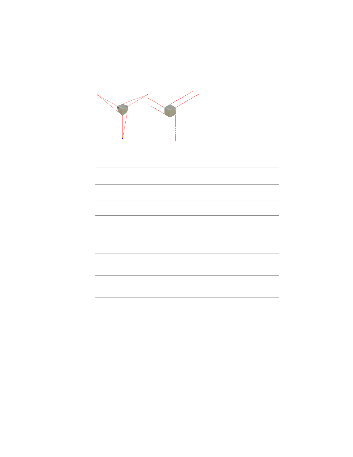
Work Points . . . . . . . . . . . . . . . . . . . . . . . . . . . . 107
Grounded Work Points . . . . . . . . . . . . . . . . . . . . . . 108
Modifying Work Features . . . . . . . . . . . . . . . . . . . . . . . . 109
Chapter 6 Using Projects to Organize Data . . . . . . . . . . . . . . . . 111
Key Terms . . . . . . . . . . . . . . . . . . . . . . . . . . . . . . . . 111
Contents | v

Learn About Projects . . . . . . . . . . . . . . . . . . . . . . . . . . . 114
Default Project . . . . . . . . . . . . . . . . . . . . . . . . . . . 114
Set an Active Project . . . . . . . . . . . . . . . . . . . . . . . . 114
How Referenced Files are Found . . . . . . . . . . . . . . . . . . 115
Setting Up Projects . . . . . . . . . . . . . . . . . . . . . . . . . . . . 116
Project Types . . . . . . . . . . . . . . . . . . . . . . . . . . . . 116
Single-user Projects . . . . . . . . . . . . . . . . . . . . . 117
Vault Projects . . . . . . . . . . . . . . . . . . . . . . . . 118
Set Up Folder Structures . . . . . . . . . . . . . . . . . . . . . . 119
Creating Projects . . . . . . . . . . . . . . . . . . . . . . . . . . . . . 120
Set Project Options . . . . . . . . . . . . . . . . . . . . . . . . . 123
Workspace . . . . . . . . . . . . . . . . . . . . . . . . . . 123
Library Locations . . . . . . . . . . . . . . . . . . . . . . 124
Library Locations for Mechanical Desktop Parts . . . . . . 125
Library Locations for iParts and iAssemblies . . . . . . . . 126
Content Center Files . . . . . . . . . . . . . . . . . . . . . 127
Other Types of Libraries In Projects . . . . . . . . . . . . . 128
Avoid Duplicate File Names . . . . . . . . . . . . . . . . . 129
Creating and Opening Files In Projects . . . . . . . . . . . . . . . . . 129
Chapter 7 Managing Assemblies . . . . . . . . . . . . . . . . . . . . . . 131
Assembly Environment . . . . . . . . . . . . . . . . . . . . . . . . . 131
Assembly Design Strategies . . . . . . . . . . . . . . . . . . . . 132
Bottom-Up Assembly Design . . . . . . . . . . . . . . . . 132
Top-Down Assembly Design . . . . . . . . . . . . . . . . . 133
Middle-Out Assembly Design . . . . . . . . . . . . . . . . 133
Assembly Coordinate System . . . . . . . . . . . . . . . . . . . 133
Assembly Constraints . . . . . . . . . . . . . . . . . . . . . . . 134
Assembly Analysis . . . . . . . . . . . . . . . . . . . . . . . . . 134
Storing Data Files In Projects . . . . . . . . . . . . . . . . . . . . . . 134
Working with the Assembly Browser . . . . . . . . . . . . . . . . . . 135
In-Place Activation . . . . . . . . . . . . . . . . . . . . . . . . . 135
Visibility of Components . . . . . . . . . . . . . . . . . . . . . 136
Assembly Structures . . . . . . . . . . . . . . . . . . . . . . . . 136
Restructure Assemblies . . . . . . . . . . . . . . . . . . . . . . . 137
Browser Display . . . . . . . . . . . . . . . . . . . . . . . . . . 138
Graphics Window Display . . . . . . . . . . . . . . . . . . . . . 139
Producing Bills of Materials . . . . . . . . . . . . . . . . . . . . . . . 140
Tips for Working with Assemblies . . . . . . . . . . . . . . . . . . . . 140
Chapter 8 Placing, Moving, and Constraining Components . . . . . . . . 141
Placing Components In Assemblies . . . . . . . . . . . . . . . . . . . 141
Drag Components into Assemblies . . . . . . . . . . . . . . . . 143
Simplify Assemblies . . . . . . . . . . . . . . . . . . . . . . . . 143
Grounded Components . . . . . . . . . . . . . . . . . . . . . . 144
vi | Contents

Other Sources of Components . . . . . . . . . . . . . . . . . . . . . . 144
Moving and Rotating Components . . . . . . . . . . . . . . . . . . . 145
Constraining Components . . . . . . . . . . . . . . . . . . . . . . . 145
Place Constraints . . . . . . . . . . . . . . . . . . . . . . . . . . 146
Mate Constraint . . . . . . . . . . . . . . . . . . . . . . . 148
Angle Constraint . . . . . . . . . . . . . . . . . . . . . . . 150
Tangent Constraint . . . . . . . . . . . . . . . . . . . . . 151
Insert Constraint . . . . . . . . . . . . . . . . . . . . . . . 152
Motion Constraints . . . . . . . . . . . . . . . . . . . . . 152
iMates . . . . . . . . . . . . . . . . . . . . . . . . . . . . 153
Viewing Constraints . . . . . . . . . . . . . . . . . . . . . . . . . . . 153
Editing Constraints . . . . . . . . . . . . . . . . . . . . . . . . . . . 154
Tips for Managing Assembly Constraints . . . . . . . . . . . . . . . . 154
Chapter 9 Creating Assemblies . . . . . . . . . . . . . . . . . . . . . . . 157
Creating Assembly Components . . . . . . . . . . . . . . . . . . . . 157
Parts In Place . . . . . . . . . . . . . . . . . . . . . . . . . . . . 157
Projected Edges and Features . . . . . . . . . . . . . . . . . . . 159
Subassemblies In Place . . . . . . . . . . . . . . . . . . . . . . . 160
Guidelines for Selecting Subassembly Components . . . . 161
Creating Component Patterns . . . . . . . . . . . . . . . . . . . . . . 161
Independent Instances . . . . . . . . . . . . . . . . . . . . . . . 163
Creating Assembly Features . . . . . . . . . . . . . . . . . . . . . . . 164
Use Assembly Features . . . . . . . . . . . . . . . . . . . . . . . 164
Using Work Features in Assemblies . . . . . . . . . . . . . . . . . . . 165
Replacing Components . . . . . . . . . . . . . . . . . . . . . . . . . 165
Mirroring Assemblies . . . . . . . . . . . . . . . . . . . . . . . . . . . 166
Copying Assemblies . . . . . . . . . . . . . . . . . . . . . . . . . . . 169
Chapter 10 Analyzing Assemblies . . . . . . . . . . . . . . . . . . . . . . 173
Checking for Interference . . . . . . . . . . . . . . . . . . . . . . . . 173
Checking for Degrees of Freedom . . . . . . . . . . . . . . . . . . . . 174
Unconstrained Drag . . . . . . . . . . . . . . . . . . . . . . . . 175
Constrained Drag . . . . . . . . . . . . . . . . . . . . . . . . . 175
Constraint Drivers . . . . . . . . . . . . . . . . . . . . . . . . . 176
Drive Constraints . . . . . . . . . . . . . . . . . . . . . . . . . 176
Animating Assembly Components . . . . . . . . . . . . . . . . . . . 178
Selecting Components . . . . . . . . . . . . . . . . . . . . . . . . . . 180
Chapter 11 Using Design Accelerator . . . . . . . . . . . . . . . . . . . . 185
What is Design Accelerator . . . . . . . . . . . . . . . . . . . . . . . 185
What operations can I perform within Design Accelerator? . . . 186
Work with Generators . . . . . . . . . . . . . . . . . . . . . . . 186
Work with Bolted Connections . . . . . . . . . . . . . . . 188
Contents | vii

Insert All Components At Once . . . . . . . . . . . . . . . 194
Work with Calculators . . . . . . . . . . . . . . . . . . . . . . . . . . 197
Author User Parts . . . . . . . . . . . . . . . . . . . . . . . . . . . . 198
Set File Names . . . . . . . . . . . . . . . . . . . . . . . . . . . 201
Chapter 12 Setting Up Drawings . . . . . . . . . . . . . . . . . . . . . . . 203
Creating Drawings . . . . . . . . . . . . . . . . . . . . . . . . . . . . 203
Edit Model Dimensions in Drawings . . . . . . . . . . . . . . . 205
Formatting Drawings with Styles . . . . . . . . . . . . . . . . . . . . 205
Use Styles In Templates . . . . . . . . . . . . . . . . . . . . . . 206
Share Styles Between Documents . . . . . . . . . . . . . . . . . 207
Use Styles Available In Drafting Standards . . . . . . . . . . . . 207
Create Styles . . . . . . . . . . . . . . . . . . . . . . . . . . . . 208
Object Defaults Styles and Layers . . . . . . . . . . . . . . . . . 209
Using Drawing Resources . . . . . . . . . . . . . . . . . . . . . . . . 210
Sheet Layouts . . . . . . . . . . . . . . . . . . . . . . . . . . . 211
Edit Default Sheets . . . . . . . . . . . . . . . . . . . . . . . . . 211
Format Sheets . . . . . . . . . . . . . . . . . . . . . . . . . . . 212
Sketch Overlays . . . . . . . . . . . . . . . . . . . . . . . 212
Drawing Borders . . . . . . . . . . . . . . . . . . . . . . . . . . 212
Title Blocks . . . . . . . . . . . . . . . . . . . . . . . . . . . . . 214
Align Title Blocks . . . . . . . . . . . . . . . . . . . . . . 216
Edit Title Blocks . . . . . . . . . . . . . . . . . . . . . . . 216
Tips for Creating Drawings . . . . . . . . . . . . . . . . . . . . . . . 216
Chapter 13 Creating Drawing Views . . . . . . . . . . . . . . . . . . . . . 219
Drawing Views . . . . . . . . . . . . . . . . . . . . . . . . . . . . . . 219
Drawing View Types . . . . . . . . . . . . . . . . . . . . . . . . 219
Base Views . . . . . . . . . . . . . . . . . . . . . . . . . . 221
Projected Views . . . . . . . . . . . . . . . . . . . . . . . 221
Editing Views . . . . . . . . . . . . . . . . . . . . . . . . . . . . . . . 221
Creating Multiview Drawings . . . . . . . . . . . . . . . . . . . . . . 222
Base Views . . . . . . . . . . . . . . . . . . . . . . . . . . . . . 222
Section Views . . . . . . . . . . . . . . . . . . . . . . . . . . . 225
Defining Section Views . . . . . . . . . . . . . . . . . . . 225
Auxiliary Views . . . . . . . . . . . . . . . . . . . . . . . . . . 228
Detail Views . . . . . . . . . . . . . . . . . . . . . . . . . . . . 229
Break Views . . . . . . . . . . . . . . . . . . . . . . . . . . . . 231
Draft Views . . . . . . . . . . . . . . . . . . . . . . . . . . . . . 232
Modifying Views and Sections . . . . . . . . . . . . . . . . . . . . . . 232
Delete Views . . . . . . . . . . . . . . . . . . . . . . . . . . . . 233
Align Views . . . . . . . . . . . . . . . . . . . . . . . . . . . . . 234
Edit Hatch Patterns . . . . . . . . . . . . . . . . . . . . . . . . 235
Rotate Views . . . . . . . . . . . . . . . . . . . . . . . . . . . . 236
Move Views . . . . . . . . . . . . . . . . . . . . . . . . . . . . 236
viii | Contents

Viewing Multiple Positions of Assemblies . . . . . . . . . . . . . . . . 236
Tips for Creating Drawing Views . . . . . . . . . . . . . . . . . . . . 237
Chapter 14 Annotating Drawings . . . . . . . . . . . . . . . . . . . . . . 239
Annotation Tools . . . . . . . . . . . . . . . . . . . . . . . . . . . . . 239
Using Styles to Format Annotations . . . . . . . . . . . . . . . . . . . 241
Working with Tables . . . . . . . . . . . . . . . . . . . . . . . . . . . 241
Hole Tables . . . . . . . . . . . . . . . . . . . . . . . . . . . . . 242
General and Configuration Tables . . . . . . . . . . . . . . . . . 242
Parts Lists . . . . . . . . . . . . . . . . . . . . . . . . . . . . . . 242
Creating Dimensions In Drawings . . . . . . . . . . . . . . . . . . . . 243
Place Dimensions . . . . . . . . . . . . . . . . . . . . . . . . . 243
Model Dimensions . . . . . . . . . . . . . . . . . . . . . . 243
Drawing Dimensions . . . . . . . . . . . . . . . . . . . . 244
Change Dimensions . . . . . . . . . . . . . . . . . . . . . . . . 245
Controlling Dimension Styles . . . . . . . . . . . . . . . . . . . . . . 245
Copy Dimension Styles among Drawings . . . . . . . . . . . . . 247
Placing Center Marks and Centerlines . . . . . . . . . . . . . . . . . . 247
Adding Notes and Leader Text . . . . . . . . . . . . . . . . . . . . . . 248
Using Hole and Thread Notes . . . . . . . . . . . . . . . . . . . . . . 249
Thread Representations . . . . . . . . . . . . . . . . . . . . . . 249
Working with Title Blocks . . . . . . . . . . . . . . . . . . . . . . . . 250
Working with Dimensions and Annotations . . . . . . . . . . . . . . 250
Turn Off Tangent Edge Displays . . . . . . . . . . . . . . . . . . 253
Add Model Dimensions . . . . . . . . . . . . . . . . . . . . . . 254
Reposition Model Dimensions . . . . . . . . . . . . . . . . . . . 255
Add Centerlines and Center Marks . . . . . . . . . . . . . . . . 256
Add Drawing Dimensions . . . . . . . . . . . . . . . . . . . . . 257
Format Dimensions . . . . . . . . . . . . . . . . . . . . . . . . 259
Add Notes and Leader Text . . . . . . . . . . . . . . . . . 260
Edit Model Dimensions . . . . . . . . . . . . . . . . . . . 261
Complete Title Blocks . . . . . . . . . . . . . . . . . . . . 262
Printing Drawing Sheets . . . . . . . . . . . . . . . . . . . . . . . . . 263
Plotting Multiple Sheets . . . . . . . . . . . . . . . . . . . . . . . . . 264
Tips for Annotating Drawings . . . . . . . . . . . . . . . . . . . . . . 264
Chapter 15 Using Content Center . . . . . . . . . . . . . . . . . . . . . . 265
About Content Center . . . . . . . . . . . . . . . . . . . . . . . . . . 265
Set and Manage Permissions . . . . . . . . . . . . . . . . . . . . 265
Content Center Library . . . . . . . . . . . . . . . . . . . . . . 266
Content Center Library Data . . . . . . . . . . . . . . . . 266
Working with Content Center . . . . . . . . . . . . . . . . . . . . . . 267
Content Center Environments . . . . . . . . . . . . . . . . . . 267
Consumer Environment . . . . . . . . . . . . . . . . . . . . . . 268
Editor Environment . . . . . . . . . . . . . . . . . . . . . . . . 269
Contents | ix

Tips for Using Content Center . . . . . . . . . . . . . . . . . . . . . . 270
Using the Publish Tool . . . . . . . . . . . . . . . . . . . . . . . . . . 270
Managing Administrative Tasks . . . . . . . . . . . . . . . . . . . . . 271
Chapter 16 Autodesk Inventor Utilities . . . . . . . . . . . . . . . . . . . 273
Editing Projects . . . . . . . . . . . . . . . . . . . . . . . . . . . . . . 273
Legacy Project Types . . . . . . . . . . . . . . . . . . . . . . . . . . . 276
Resolving File Links . . . . . . . . . . . . . . . . . . . . . . . . . . . 276
Search for Library and Non Library Files . . . . . . . . . . . . . 278
Search for Library References . . . . . . . . . . . . . . . . 278
Search for Non Library Locations . . . . . . . . . . . . . . 279
Use Substitution Rules to Find Missing Files . . . . . . . . . . . 279
Keeping Old File Versions . . . . . . . . . . . . . . . . . . . . . . . . 281
Moving, Copying, and Archiving Design Files . . . . . . . . . . . . . 283
Zip Files . . . . . . . . . . . . . . . . . . . . . . . . . . . . . . 284
Temporary Root Folders . . . . . . . . . . . . . . . . . . . . . . 285
Pack and Go . . . . . . . . . . . . . . . . . . . . . . . . . . . . 286
Design Assistant Manager . . . . . . . . . . . . . . . . . . . . . 287
Move and Copy Files Between Projects . . . . . . . . . . . . . . 288
Deleting Files . . . . . . . . . . . . . . . . . . . . . . . . . . . . . . . 289
Changing File Structure . . . . . . . . . . . . . . . . . . . . . . . . . 290
About Autodesk Vault . . . . . . . . . . . . . . . . . . . . . . . . . . 291
Index . . . . . . . . . . . . . . . . . . . . . . . . . . . . . . . 293
x | Contents

Introducing Autodesk Inventor
Welcome to Autodesk® Inventor™. This book explains the fundamental skills to start using
Autodesk Inventor. In these chapters, the basic features are presented through examples and
step-by-step procedures. The data files used in the procedures are installed with the Autodesk
Inventor software.
1
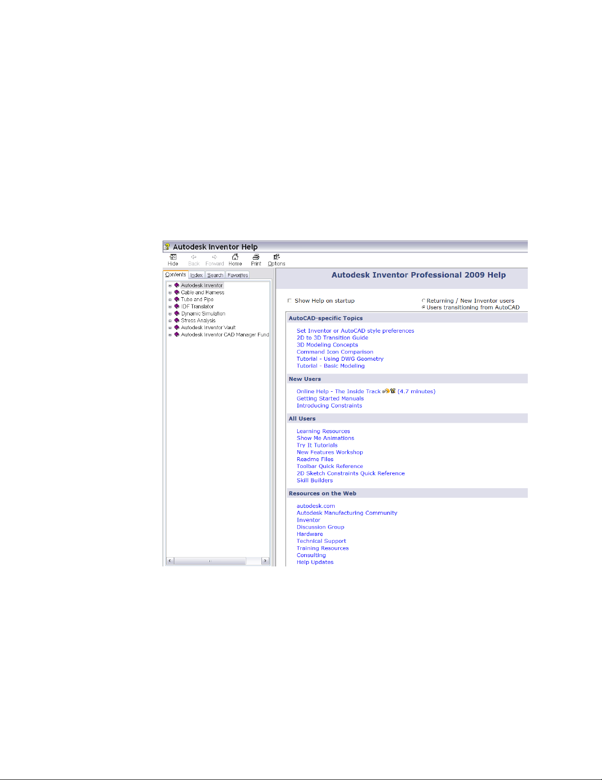
Getting Started
Autodesk Inventor provides options during installation. The options selected
determine what you see the first time you start Autodesk Inventor. If you indicate
during installation that you are a new or returning Autodesk Inventor user, you
are presented with the Open dialog box. If you indicated that you are
transitioning to Autodesk Inventor from AutoCAD®, an empty part file is
displayed (like opening a new DWG file during AutoCAD start-up). The main
Autodesk Inventor Help page is displayed with slightly different selections
depending on the selected install options. No matter how Autodesk Inventor
was installed, you can tailor the start-up experience through settings in the
Application Options dialog box to suit your needs. You can specify that Autodesk
Inventor always starts with the Open dialog box or always starts in a new file.
You can decide if you want to see Help on start-up or not (and which version
of the main Help page to see).
Projects
Autodesk Inventor uses projects to represent a logical grouping of a complete
design project. A project organizes your data by maintaining information about
1

where design data is stored, where you can edit files, and maintains valid links
between them. You use projects when you work in a team, work on multiple
design projects, and share libraries among several design projects. See
ProductName Utilities on page 273, for detailed information about setting up
and using projects.
Data Files for Exercises
When you install Autodesk Inventor, a project called tutorial_files is created.
Make this project active so that you can locate the data files that are used for
some exercises in this book.
TRY IT: Make the tutorial_files project active
1 In Autodesk Inventor, on the Standard toolbar, click Files ➤ Projects.
2 On the Project Editor, Select Project pane, double-click the tutorial_files
project to make it the active project.
In the Edit Project pane, in Location, the path to the folder containing
the tutorial data files is displayed. It is the folder where the files you create
and edit while performing the exercises are saved.
3 Close the Project Editor dialog box.
4 Click File ➤ Open.
The data files contained in the tutorial_files project are listed in the Open
File dialog box.
5 Click a file to see a preview of it, and double-click a file to open it in
Autodesk Inventor.
File Types
Once you activate a project, you can open an existing file or start a new file.
Click New to see the New File dialog box with templates for a new part,
assembly, presentation file, sheet metal part, weldment, or drawing. You can
choose from several templates with predefined units.
Templates are stored in the Autodesk\Inventor(version number)\Templates
directory or in the English or Metric subdirectories. Subdirectories in the
Templates directory are displayed as tabs in the Open New File dialog box. You
can create and save custom templates in the Templates directory.
2 | Chapter 1 Introducing Autodesk Inventor

A template can contain property information, such as part and project data,
and drawing views. You can see information stored in a file by viewing its
properties.
TRY IT: View the Properties dialog box
■ With a file open, right-click a component in the browser or in the graphics
window, and then choose Properties from the menu.
■ Click the tabs to see properties.
Application Options
You can change the look and feel of Autodesk Inventor using settings on the
Application Options dialog box. On the Standard toolbar, select Tools ➤
Application Options. Use the tabs on the Options dialog box to control the
color and display of your Autodesk Inventor work environment, the behavior
and settings of files, the default file locations, and a variety of multiple-user
functions.
Application options remain in effect until you change them.
Document Settings
You can specify settings in individual files. On the Standard toolbar, select
Tools ➤ Document Settings to display the Document Settings dialog box.
Click the tabs to view and specify settings for the active document, such as
indicating the active styles, units of measure, sketch and modeling preferences,
bill of materials, and default tolerance.
Styles and Standards
You select a drafting standard when you install Autodesk Inventor, and it
includes a default set of styles that control most objects used in documents,
such as balloons, dimensions, text, layers, parts lists, symbols and leaders,
materials, and lighting. Usually the default styles are enough to get you started,
but you can use the Styles and Standards Editor to create, modify, and purge
unused styles.
Application Options | 3

By default, actions such as creating or modifying styles affect only the current
document. You can choose to save the style to the style library, a master library
that contains definitions for all available styles associated with a drafting
standard. Usually, the style library is managed by a CAD administrator. This
practice ensures that the style definitions, used by all documents that use the
drafting standard, are not accidentally replaced by a custom style.
Style libraries make it easy to share formatting conventions across projects
because they contain the definitions of formatting objects. Using a style library,
you can update a style for all documents, such as revising the arrow heads of
dimensions, by editing the style and saving the revision to the master style
library. All documents that use that drafting standard have access to the library
and any new or changed styles that are added to it.
TRY IT: View the Styles and Standards Editor dialog box
1 In Autodesk Inventor, click File ➤ New and select the drawing template.
2 On the Standard toolbar, click Format ➤ Styles Editor.
3 On the Styles and Standards Editor dialog box, click Standard in the Style
Type browser, and then double-click a listed standard.
4 Click the General tab to see the values controlled there, and then click
the Available Styles tab to see the list of styles. As you click through the
style type list, you may notice that most names are checked. If the check
box is cleared, that style is not available for use in the current document.
5 In the left pane of the Styles and Standards Editor, click the Dimension
style, and then double-click one of the dimension styles to display it in
the right pane. Click through the tabs to see the settings for units,
alternate units, text, tolerance, options, and notes and leaders. Click a
different dimension style to see if any of the values differ.
6 In the top-right corner of the dialog box, click the Filter list and change
the filter type. Notice how the list of available styles changes if you select
All Styles, Local Styles (for the current document), or Active Standard.
You may notice differences in the lists because the local styles may have
had some unused styles purged to make the file size smaller.
7 Click Done. Any changed values are discarded.
If you click Save to preserve changes, the changes are saved only in the
current document.
4 | Chapter 1 Introducing Autodesk Inventor

Using Shortcut Keys and Command Aliases
Autodesk Inventor provides shortcut keys and command aliases to help you
perform certain tasks more quickly. A command alias is an alphanumeric
character or character sequence used to start a command. Define a shortcut
by using any of the following keys or key combinations:
■ A punctuation key (including ` - = [ ] \ ; ' , . /), or one of the following
virtual keys: Home, End, Page Up, Page Down, Up Arrow, Down Arrow.
■ A combination of the SHIFT key along with a numeric key (0-9),
punctuation key, or one of the following virtual keys: Home, End, Page
Up, Page Down, Up Arrow, Down Arrow.
■ Any combination of SHIFT, CTRL, and ALT keys along with an alphanumeric
character.
Remember that some shortcut keys and command aliases are active in specific
environments only.
TRY IT: View a complete guide to shortcut keys and command aliases
1 Open Autodesk Inventor.
2 On the Standard menu, click Tools ➤ Customize ➤ Keyboard tab. For
each category, there is a list of the command name and its associated
shortcut or alias, if one exists.
3 Click through several categories to see the associated commands.
The following is a list of some of the commonly used shortcut keys and
command aliases.
ResultKey
Displays Help for the active command or dialog box.F1
Pans the graphics window.F2
Zooms in or out in the graphics window.F3
Rotates objects in the graphics window.F4
Using Shortcut Keys and Command Aliases | 5

ResultKey
Returns to the previous view.F5
Returns to isometric view.F6
Adds a balloon to a drawing.B
Adds an assembly constraint.C
Adds a dimension to a sketch or drawing.D
Adds an ordinate dimension to a drawing.DO
Extrudes a profile.E
Adds a feature control frame to a drawing.FC
Adds a hole feature.H
Creates a line or arc.L
Places a component in the current assembly.P
Creates a revolved feature.R
Creates a 2D sketch on a face or plane.S
Tweaks a part in the current presentation file.T
Quits a command.ESC
Deletes selected objects.DELETE
In the active Line tool, removes the last sketched segment.BACKSPACE
In assemblies, applies a mate constraint.ALT + drag mouse
6 | Chapter 1 Introducing Autodesk Inventor

tool
ResultKey
In a sketch, moves spline shape points.
Activates the Select tool menu.SHIFT + right-click
Automatically rotates model in graphics window. Click to quit.SHIFT + Rotate
Return to previous editing state.CTRL + ENTER
Activates Redo (revokes the last Undo).CTRL + Y
Activates Undo (revokes the last action).CTRL + Z
Spacebar
NOTE Click Help ➤ Shortcut Quick Reference to see the list of command names
and associated shortcuts and aliases in the active environment.
Viewing Models
Use viewing tools to view a model:
■ Use the ViewCube to orbit your 3D model and to switch between standard
and isometric views.
■ Use the SteeringWheels to access a variety of navigational tools.
■ Select one of the viewing tools in the Standard toolbar to achieve a specific
view.
■ Right-click in the graphics window, and then select Isometric View from
the menu. The view vector changes to the isometric orientation.
■ Right-click in the graphics window, and then select Previous View from
the menu. The view changes back to the previous view.
■ Press F5 to return the model to the last view.
When the 3D Rotate tool is active, switches between dynamic rotation and standard isometric and single plane views.
Viewing Models | 7
To rotate a view in 3D, use the Free Orbit or Constrained Orbit tool in the
Standard toolbar to rotate a view around one of the coordinate axes.
Zoom Tools
The zoom tools are located in the Standard toolbar and are also available from
the SteeringWheels.
Zoom
Use the Zoom tool on the Standard toolbar to enlarge or reduce the image in
the graphics window. Click the tool. In the graphics window, press the cursor
as you move it up or down to zoom the view dynamically in or out. You can
zoom the view while other tools are active.
Zoom All
Use the Zoom All tool on the Standard toolbar to resize the image of a part or
assembly so that all elements are displayed in the graphics window. You can
zoom a drawing so that the active sheet fits within the graphics window.
8 | Chapter 1 Introducing Autodesk Inventor

Zoom Window
Use the Zoom Window tool on the Standard toolbar to define an area of a
part, assembly, or drawing to fill the graphics window.
Zoom Selected
Use the Zoom Selected tool on the Standard toolbar to zoom a selected edge,
feature, or other element to the size of the graphics window.
Pan
Use the Pan tool on the Standard toolbar to move the view in the graphics
window in any direction planar to the screen. You can pan the view while
other tools are active.
Pan | 9
Look At
Rotate
Use the Look At tool on the Standard toolbar to zoom and rotate the display
in the graphics window. You can position a selected planar element parallel
to the screen or position a selected edge or line horizontal to the screen.
Use the Orbit tools on the Standard toolbar to:
■ Rotate a part or assembly in the graphics window.
■ Display standard, isometric, and single plane projections of a part or
assembly.
■ Redefine the isometric view.
10 | Chapter 1 Introducing Autodesk Inventor

Shaded, Hidden Edge, and Wireframe Display
Use one of the Change Display tools to switch among the three display modes:
Shaded, Hidden Edge, and Wireframe. You can apply display modes to part
and assembly models, and to views in the Engineer's Notebook.
Ground Shadow Display
Use the Ground Shadow tool to cast a shadow on the plane beneath the model.
Orthographic and Perspective Camera Views
The Camera View tool has two settings: Orthographic Camera mode and
Perspective Camera mode.
In Perspective Camera mode, part or assembly models are displayed in
three-point perspective, a visual effect where parallel lines converge on a
Shaded, Hidden Edge, and Wireframe Display | 11
vanishing point. It is the way real objects are perceived by the human eye or
by a camera.
The following chart shows how the other viewing tools behave and how they
can be modified in each camera mode.
Zoom or
Pan Type
era Target Point Zoom
Zoom
tion
Orthographic
Camera mode
Camera mode
Importing and Exporting Data
You can import Pro/ENGINEER®, Parasolid®, SolidWorks™, UGS NX, SAT,
STEP, IGES, and AutoCAD and Autodesk® Mechanical Desktop® (DWG) files
for use in Autodesk Inventor. You can export AAutodesk Inventor parts and
assemblies to many file formats, including Pro/ENGINEER and Parasolid, and
Keys/CommandsPerspective
F2 PanYesYesCamera Translation Pan
SHIFT+F2 PanYesYesCamera Pivot Pan
F3 ZoomYesYesCamera Position Zoom
SHIFT+F3 ZoomYesNoCamera Position/Cam-
CTRL+F3 ZoomYesNoLens Focal Length
SHIFT+CTRL+F3 ZoomSet Perspective Distor-
12 | Chapter 1 Introducing Autodesk Inventor

you can export Autodesk Inventor drawings as DXF™ or AutoCAD drawing
(DWG) files.
The options for importing and saving AutoCAD files in Autodesk Inventor
are:
■ Selection of layers.
■ Window selection of entities.
■ Saving files in DWG format.
■ Support for DXF files back to version 12.
■ Creation of AutoCAD
installed.
NOTE Mechanical Desktop files can be linked to Autodesk Inventor assemblies
without importing.
AutoCAD Files
When you open an AutoCAD file in Autodesk Inventor, you can specify the
AutoCAD data to translate. You can select:
■ Model space, a single layout in paper space, or 3D solids.
®
Mechanical files, if AutoCAD Mechanical is
■ One or more layers.
You can also place 2D translated data:
■ On a sketch in a new or existing drawing.
■ As a title block in a new drawing.
■ As a sketched symbol in a new drawing.
■ On a sketch in a new or existing part.
If you translate 3D solids, each solid becomes a part file containing an ASM
solid body. Blocks are translated as sketched symbols.
When you import AutoCAD (DWG) drawings into a part sketch, a drawing,
or a drawing sketch overlay, the converter takes the entities from the XY plane
of model space and places them on the sketch. In a drawing, certain entities,
such as splines, cannot be converted.
AutoCAD Files | 13

When you export Autodesk Inventor drawings to AutoCAD, the converter
creates an editable AutoCAD drawing and places all data in paper space or
model space in the DWG file. If the Autodesk Inventor drawing has multiple
sheets, each is saved as a separate DWG file. The exported entities become
AutoCAD entities, including dimensions.
You can open a .dwg file and then copy selected AutoCAD data to the clipboard
and paste into a part, assembly, or drawing sketch. The data is imported at
the cursor position.
Autodesk Mechanical Desktop Files
Autodesk Inventor can translate Autodesk Mechanical Desktop parts and
assemblies so the design intent is preserved. You can import a Mechanical
Desktop file as either an ASM body or a full conversion when Mechanical
Desktop is installed and running on your system. Using the DWG/DXF File
Import Wizard, you can import Mechanical Desktop data, including parts,
assemblies, and drawings. The data is associative to Autodesk Inventor drawing
views and annotations.
Features that are supported in Autodesk Inventor are converted. Unsupported
features t are not translated. If Autodesk Inventor cannot translate a feature
it skips that feature, places a note in the browser, and then completes the
translation.
Files from Other Applications
You can open and change models created in Pro/ENGINEER, Parasolid,
SolidWorks, and UGS NX. Autodesk Inventor translates assembly and part
files, solids, multi-solids, surfaces, and more. After the import operation is
complete, you can change the model as if it was originally created in Autodesk
Inventor.
After changing a file, you can continue to use it as an Autodesk Inventor file
or export it to other file formats, including Pro/ENGINEER and Parasolid.
14 | Chapter 1 Introducing Autodesk Inventor

SAT Files
SAT (*.sat) files contain nonparametric solids that can be Boolean solids or
parametric solids with the relationships removed. You can use a SAT file in
an assembly and add parametric features to the base solid.
When you import a SAT file that contains a single body, it produces an
Autodesk Inventor part file with a single part. If it contains multiple bodies,
it produces an assembly with multiple parts. Surface data in a SAT file is also
supported.
STEP Files
STEP files are the international format developed to overcome some of the
limitations of data conversion standards. Past efforts in developing standards
have resulted in localized formats such as IGES (U.S.), VDAFS (Germany), or
IDF (for circuit boards). Those standards do not address many developments
in CAD systems. The STEP converter for Autodesk Inventor is designed for
effective communication and reliable interchange with other CAD systems.
When you import a STEP (*.stp, *.ste, *.step) file, only 3D solid, part, surface,
and assembly data are converted. Drafting, text, and wireframe data are not
processed by the STEP converter. If a STEP file contains one part, it produces
an Autodesk Inventor part file. If it contains assembly data, it produces an
assembly with multiple parts.
IGES Files
IGES (*.igs, *.ige, *.iges) files are a standard in the United States. Many NC/CAM
software packages require files in IGES format. Autodesk Inventor imports and
exports IGES files, including wireframe data.
DWF Files
Design Web Format (DWF™) is a compressed, secure format used to publish
CAD data. DWF files are fast to open and view, and can easily be shared by
e-mail with customers, vendors, marketing, and others who do not have
Autodesk Inventor installed. Use the DWF Publisher to publish an accurate
SAT Files | 15

visual representation of 2D and 3D data in one file. Download and install the
free Autodesk Design Review viewer to view a DWF file.
Learning Autodesk Inventor
You can select a learning tool that suits your preferred learning style. You can
get help for the current task, follow a workflow in a tutorial or Show Me
animation, learn a new skill using a Skill Builder, or click through Help topics.
You can gain 3D knowledge as you transition from 2D and watch animations
of operations.
Be more productive with Autodesk software. Get trained at an Autodesk
Authorized Training Center (ATC®) with hands-on, instructor-led classes to
help you get the most from your Autodesk products. Enhance your productivity
with proven training from over 1,400 ATC sites in more than 75 countries.
For more information about Autodesk Authorized Training Centers, contact
atc.program@autodesk.com or visit the online ATC locator at
www.autodesk.com/atc.
Using Technical Publications
Autodesk Inventor integrates software tools, knowledge, and interactive
learning for assistance in specific work tasks and to increase your productivity.
The complete set of technical publications includes:
®
■ Printed Getting Started manual
■ Help
■ Help for the AutoCAD user
■ Welcome modules
■ Tutorials
■ Show Me animations
■ New Features Workshop to explore what’s new in Autodesk Inventor
■ User comments links
■ Skill Builders
16 | Chapter 1 Introducing Autodesk Inventor
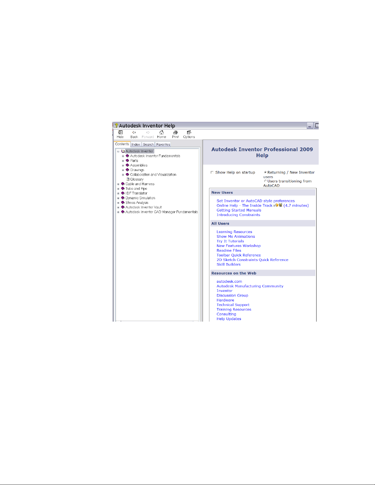
Help
Click Help ➤ Help topics for easy access to the Help topics, Skill Builders,
and Tutorials. You can also navigate through the Table of Contents or use the
Index and Search functions.
When using Autodesk Inventor, click Help buttons on dialog boxes to retrieve
a reference topic automatically that describes options for the dialog box.
Help | 17
Help for AutoCAD Users
In Autodesk Inventor, click Help. If you selected “Users transitioning from
AutoCAD” as your preference during the installation, your Help home page
opens with topics and tutorials that ease the transition from 2D to 3D. You
can also navigate to them through the AutoCAD Topics section in the Table
of Contents. There are explanations of the differences between designing in
2D and 3D, equivalents to AutoCAD commands, tutorials, and a workflow to
explain everything from sketching to presentations.
18 | Chapter 1 Introducing Autodesk Inventor
Tutorials and Show Me Animations
Online tutorials are step-by-step illustrated lessons that show you how to
create and document your designs. You can access them from the Help home
page or click Help ➤ Tutorials.
Show Me animations are videos that show step-by-step instructions how to
complete an operation. You can access Show Me animations from the Standard
toolbar, the Help home page, and in individual help topics.
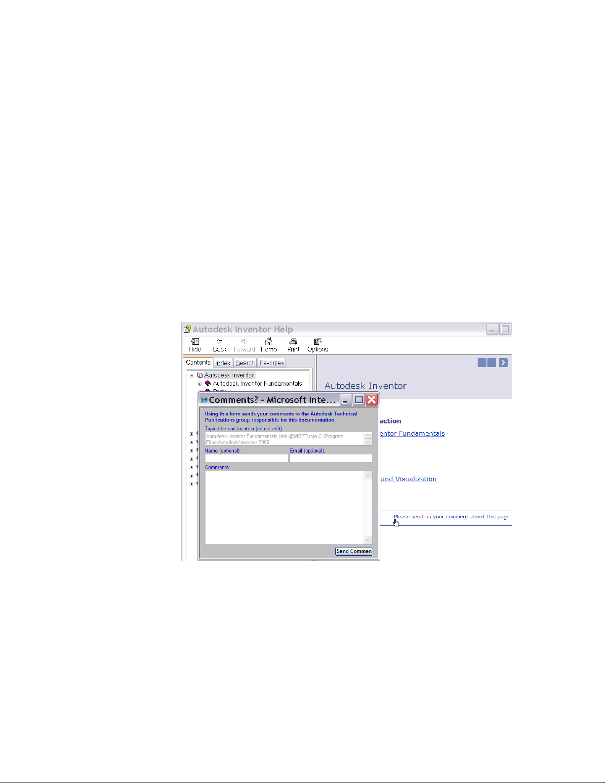
Feedback Links
Click the Comments Link on a Help topic page to address specific topics,
provide general feedback about the topic, and submit input about what you
want and need from the Autodesk Inventor Technical Publications team.
Tutorials and Show Me Animations | 19
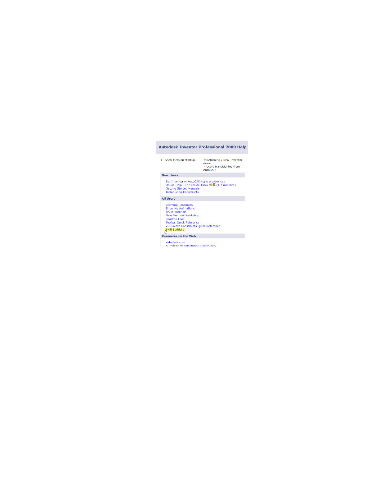
Skill Builders
Autodesk Inventor provides extended learning through its Skill Builders
learning modules. Skill Builders are posted throughout a release cycle on the
Web to address customer needs and requests.
You can access them (if you have Internet access) by clicking the link on the
Help home page.
20 | Chapter 1 Introducing Autodesk Inventor

Creating Sketches
2
In Autodesk® Inventor™, sketching is the first step in creating a part. This chapter gives you
an overview of the sketch environment and the workflow for creating sketches.
Understanding Sketches
Most parts start with a sketch. A sketch is the profile of a feature and any
geometry (such as a sweep path or axis of rotation) required to create the feature.
All sketch geometry is created and edited in the sketch environment, using
Sketch tools on the panel bar. You can control the sketch grid, and use sketch
tools to draw lines, splines, circles, ellipses, arcs, rectangles, polygons, or points.
You can fillet corners, extend or trim curves, and offset and project geometry
from other features.
To start a sketch from scratch, open a new part file, select a Sketch tool, and
then start sketching in the graphics window. As you sketch, constraints are
automatically applied to the various sketch elements as you sketch. For example,
if you sketch a line nearly horizontal, a horizontal constraint is implied. You
can modify or delete any implied sketch constraint. You can also add constraints
manually to any sketch element. To exit a given sketch tool right-click, and
then select Done, or press ESC.
You create a 3D model from a sketch by extruding the profile or revolving it
around an axis.
21

The model you create in Autodesk Inventor is linked to its underlying sketches
and sketch information. If you change a sketch, the model is automatically
updated.
Sketch Environment
When you create or edit a sketch, you work in the sketch environment. The
sketch environment consists of a sketch and sketch tools to control the sketch
grid, and to draw lines, splines, circles, ellipses, arcs, rectangles, polygons, or
points.
When you open a new part file, the sketch environment is active. The 2D
Sketch button is selected, and the Sketch tools are available, along with a
sketch plane on which to sketch. You can control the initial sketch setup by
using template files or settings on the Sketch tab of the Application Options
dialog box. Click Tools ➤ Application Options ➤ Sketch tab to customize
the settings.
When you create a sketch, a sketch icon is displayed in the browser. When
you create a feature from a sketch, a feature icon is displayed in the browser
with the sketch icon nested under it. When you click a sketch icon in the
browser, the sketch is highlighted in the graphics window.
After you create a model from a sketch, re-enter the sketch environment to
make changes or start a new sketch for a new feature. In an existing part file,
first activate the sketch in the browser. This action activates the tools in the
sketch environment. You can create geometry for part features. The changes
you make to a sketch are reflected in the model.
22 | Chapter 2 Creating Sketches

Sketch Coordinate System
When you start a new sketch, the sketch coordinate system is displayed as X
and Y axes of the sketch grid. You can turn on the 3D indicator to display it
at the sketch origin. (Click Tools ➤ Application Options ➤ Sketch tab. In
the Display box, select the Coordinate System Indicator check box.) The default
grid lies on the sketch plane.
You can reposition and change orientation of the sketch coordinate system
to:
■ Change the orientation of dimensions you create.
■ Aid in precise input for sketch geometry.
TRY IT: Reposition the sketch origin in the coordinate system
1 Open a part file. In the browser, click the plus sign in front of a feature
to expand the display.
2 In the expanded feature display, right-click the sketch, and then click
Edit Coordinate System on the menu.
In the graphics window, the axis icon is displayed for the highlighted
sketch.
3 On the axis icon, click the red arrow to realign the X axis, the green arrow
to realign the Y axis, or the blue centroid to relocate the origin.
4 Select one of the following methods to relocate the highlighted axis:
■ A feature vertex to move the coordinate system.
■ A feature edge to rotate the coordinate system.
To flip the axis, right-click and select Flip axis from the menu.
5 Right-click, and then click Done to activate the new coordinate system.
The sketch origin in the coordinate system is repositioned.
Sketch Coordinate System | 23

Using Model Edges as References for Sketches
While you sketch, you can:
■ Automatically project edges of the part to the sketch plane as you sketch
a curve.
■ Create dimensions and constraints to edges of the part that do not lie on
the sketch plane.
■ Control the automatic projection of part edges to the sketch plane.
Workflow overview: Project part edges to a sketch plane
■ Click the Project Geometry tool, and then select any part edge.
■ Select an edge of the part while creating a dimension or constraint.
NOTE You can also use model edges as references for continuous loops or points.
Precise Values
In the sketch environment, you can enter relative X and Y distances from the
last point selected. The tools for precise input are located on the Precise Input
toolbar. It is only available when a sketch tool that requires placement of a
point is activated. For example, you can use precise input to define a line, a
sketch point, and a three-point arc, among others.
Enter precise values for geometry as you sketch. The Precise Input toolbar has
X and Y fields. You can enter both values to define a point, or enter only X
or Y to limit the placement of the point to a vertical or horizontal line.
TRY IT: Input precise values
1 In the sketch environment, click a Sketch tool to make it active.
2 On the standard toolbar, click View ➤ Toolbar ➤ Autodesk Inventor
Precise Input.
The toolbar is displayed in the graphics window.
3 Click a start point, or on the Precise Input dialog box, enter a value in
the X field.
24 | Chapter 2 Creating Sketches

4 Press TAB to activate the Y field, and then enter a value.
5 Press ENTER to accept your input.
The sketch is drawn according to the input.
6 Right-click and select Done to end the sketch tool.
Creating Sketches
In this exercise, you create a part file, and then create sketch geometry using
basic sketching techniques. The following illustrates a completed sketch and
sketched feature.
Create Sketches
When you open a new part file, the Sketch environment is active.
The current grid setting provides a visual clue to the size of sketches. Use
Application Options and Document Settings to define the grid display.
TRY IT: Modify the sketch grid display
1 Click Tools ➤ Application Options.
2 On the Sketch tab, define the grid line display. You can also select the
Snap to Grid setting.
TRY IT: Modify the grid spacing
1 Click Tools ➤ Document Settings.
2 Select the Sketch tab and make adjustments, as needed.
Creating Sketches | 25

TRY IT: Start a sketch
1 On the standard toolbar, click File ➤ New. On the Metric tab,
double-click Standard(mm).ipt.
The new part is listed in the browser, and the sketch environment is
active.
2 On the 2D Sketch panel bar, click the Line tool. Click the left side of the
graphics window to specify a first point, move the cursor to the right
approximately 100 units, and then click to specify a second point.
As you sketch, the position of the current point, length, and angle of the
line are dynamically displayed in the lower right border of the graphics
window.
NOTE Use the Zoom tool to zoom out if a line of 100 units does not fit in the
graphics window.
The position of the current line point is relative to the sketch 0,0 coordinates.
The line angle is relative to the sketch X axis. Symbols to indicate implied
constraints are displayed next to the current line point as you sketch.
TRY IT: Complete the sketch
1 Move the cursor up approximately 40 units, and then click to create a
perpendicular line.
2 Move the cursor to the left and create a horizontal line of approximately
30 units. The parallel constraint symbol is displayed.
26 | Chapter 2 Creating Sketches

3 Move the cursor down and create a vertical line of approximately 10
units.
4 Move the cursor to the left to create a horizontal line of approximately
40 units.
5 Move the cursor up until the parallel constraint symbol is displayed and
a dotted line appears. Click to specify a point.
6 Move the cursor left until the parallel constraint symbol is displayed and
a dotted line appears, and then click to specify a point.
Create Sketches | 27

7 Move the cursor down until it touches the first point you specified at the
beginning of the exercise. When the coincident constraint symbol is
displayed, click to close the sketch.
8 In the graphics background, right-click and select Done.
9 Right-click again and select Finish Sketch.
The sketch is completed. Do not save the file.
Create Profiles with Tangencies
In this exercise, you create a part file, and then use basic sketching techniques
to create a simple profile. The profile consists of lines and tangential arcs.
TRY IT: Create a sketch
1 Click the New tool on the standard toolbar, select the Metric tab, and
then double-click Standard(mm).ipt.
A new part and sketch are listed in the browser. The sketch environment
is active.
28 | Chapter 2 Creating Sketches

2 On the standard toolbar, click View ➤ Toolbar ➤ Autodesk Inventor
Precise Input to display the Precise Input toolbar.
3 Click the Line tool on the panel bar or on the 2D Sketch panel toolbar.
Click the center of the graphics window, and then enter 65 in the X field
of the Precise Input toolbar. Move the cursor to the right to display the
horizontal constraint symbol, and then click to create a 65-mm horizontal
line.
4 On the Precise Input dialog box, click the Y field, and then enter 15.
Move the cursor to display the perpendicular constraint symbol, and
then click the second point. A perpendicular line of 15 units is sketched.
NOTE Use the Zoom tool to zoom out and view the entire line if it is not
visible in the graphics window.
5 Move the cursor up and to the left, and then click to create a sloping line.
The exact angle is not important.
TRY IT: Complete the sketch
1 Click the end of the line, hold, and drag the endpoint to create a tangent
arc. Release the mouse button to place the endpoint of the arc.
Create Profiles with Tangencies | 29

2 Move the cursor to the start point of the profile and click when the
coincident constraint symbol is displayed.
3 In the graphics background, right-click, and select Done, and then
right-click and select Finish Sketch.
The sketch is completed. Do not save the file.
Drag Sketch Geometry
After you create sketch geometry, and while it is unconstrained or
underconstrained, you can drag it to resize it.
Tips for Sketching
■ Start a line by dragging off a circle or an arc.
Drag radially for a perpendicular line or drag tangentially for a tangent
line.
■ Start a line by dragging off the interior (not the endpoints) of another line
and drag in a perpendicular direction.
The new line is constrained perpendicular to the existing line.
■ Create an arc by dragging off the end of a line.
Return the pointer to the endpoint of the line to change the direction of
an arc.
■ Start a spline tangent to a line by dragging off the line.
Select the endpoint of a line, and then drag it in the direction of tangency
to end a spline tangent to a line.
■ Create coincident constraints.
30 | Chapter 2 Creating Sketches

When you start a new line, arc, or circle from an existing line, Autodesk
Inventor can infer a coincident constraint to the midpoint, endpoint, or
interior of the line.
■ Use SHIFT to drag.
All drag features, except for a tangent spline, are also available by pressing
and holding SHIFT while moving the cursor.
■ Drag multiple lines, curves, or points at the same time.
Select the geometry, and then drag the last item you selected.
■ Switch between the Trim and Extend tools.
Press SHIFT or select the other tool from the context menu to switch
between Trim and Extend.
Constraining Sketches
Constraints limit changes and define the shape of a sketch. For example, if a
line is horizontally constrained, dragging an endpoint changes the length of
the line or moves it vertically, but does not affect its slope. You can place
geometric constraints between two objects in the same sketch, or between a
sketch and geometry projected from an existing feature or a different sketch.
Constraints are automatically applied when you sketch. For example, if the
horizontal or vertical symbol is displayed when you create a line, then the
associated constraint is applied. Depending on how accurately you sketch,
one or more constraints may be required to stabilize the sketch shape or
position.
Although you can use unconstrained sketches, fully constrained sketches result
in more predictable updates.
NOTE The term constraints is often used in Autodesk Inventor to refer to both
geometric constraints and dimensions. Remember that dimensions and geometric
constraints work together to create a sketch that meets design intent.
Add Constraints
Define your design intent by adding geometric constraints to the sketch. You
can use autodimensioning to confirm whether a sketch is fully constrained
and apply any needed constraints. You can also create constraints by inference
Constraining Sketches | 31

by dragging geometry until the cursor brushes the geometry you want to
constrain.
To view or remove constraints, use the Show Constraints tool on the 2D Sketch
panel toolbar. Alternatively, right-click in the graphics window, and then use
options on the menu to show or hide all constraints at once. To delete a
constraint, select a constraint symbol, right-click, and then select Delete.
Some geometric constraints work only with lines, while others work only with
arcs, circles, or radial features.
Open Data Files for Exercises
The location of data files for the exercises in this manual are specified in the
project called tutorial_files. This project must be activate so you have access
to the required files. Once the project is active, you can open the tutorial files.
TRY IT: Activate the project file and open the tutorial file for an exercise
1 Close any open Autodesk Inventor files.
2 On the standard toolbar, click File ➤ Projects.
3 On the Project Editor, top pane, double-click the tutorial_files project to
make it the active project. Click Done.
4 Click File ➤ Open.
5 On the Open dialog box, click the file consketch.ipt see a preview of it,
and double-click it to open it.
The file opens in Autodesk Inventor. You are ready to start the exercise.
32 | Chapter 2 Creating Sketches

Add Constraints to the First Sketch
In this exercise, you practice adding geometric constraints to an existing sketch
containing three closed loops. In some cases, you can greatly reduce the
number of dimensional constraints required on a sketch.
This exercise contains geometry that does not meet design criteria and requires
additional geometric constraints to comply with the design intent.
TRY IT: Add constraints to the first sketch
1 On the standard toolbar, click the Look At tool, and then select any curve.
The plan view is displayed.
2 Click the Zoom All tool on the standard toolbar to view the three loops.
3 In the browser, double-click Sketch1 to make it active.
4 On the standard toolbar, click the Zoom Window tool, and then draw a
window around the sketch loop on the left.
The sketch loop is centered on your screen.
5 Right-click the graphics window, and select Show All Constraints. The
current sketch constraints are displayed.
6 Move the cursor over the constraint glyphs to highlight the sketch
geometry that is constrained.
In this example, you want the sloping lines in the sketch to be vertical,
so you now add a vertical constraint.
7 Right-click the graphics window, and select Hide All Constraints.
8 Click the down arrow beside the Constraint tool in the 2D Sketch panel
bar, and then click the Vertical constraint tool.
NOTE The cursor displays the constraint type. In this case, the vertical symbol
is displayed.
Add Constraints to the First Sketch | 33

Click the three sloping lines (be sure that you do not select the midpoint
of the lines).
Your sketch should look like the one in the following figure.
9 Right-click the graphics window, and select Done.
10 Right-click the graphics window, and select Show All Constraints.
11 All constraints display as shown in the following figure.
12 Right-click the graphics window, and select Hide All Constraints.
13 Click Return on the standard toolbar to exit the sketch.
Add Constraints to Existing Sketches
Constraints can be added to a sketch after it is created. In this procedure, you
add constraints to the second sketch.
To redisplay all of the sketches, use the Zoom All tool on the standard toolbar.
TRY IT: Add constraints to a sketch
1 Double-click Sketch2 in the browser.
2 On the standard toolbar, click the Zoom Window tool, and then drag a
window around the second sketch loop.
The second sketch loop is centered on your screen.
34 | Chapter 2 Creating Sketches

3 Click the arrow beside the Constraint tool on the panel bar or on the 2D
Sketch panel toolbar to open the pop-up menu. Click the Collinear
constraint tool. Click the horizontal lines at the top of the sketch.
Your sketch should look like the following figure. Note the collinear lines
identified by the red arrows.
4 Press ESC to cancel the Collinear constraint tool. Drag the top-right
horizontal line down and note how the sketch changes. This technique
is known as constrained drag.
5 Click the down arrow beside the Constraint tool again, and then click
the Equal constraint tool. Click the horizontal line at the lower left of
the sketch and then click the horizontal line at the upper left.
Make the two horizontal lines on the right side equal to the line at the
lower left.
Your sketch should look like the following figure.
6 Press ESC to cancel the Constraint tool. Drag the right vertical line and
note how the sketch changes. With the equal constraint applied, the
sketch retains its symmetry as you drag the vertical lines.
Add Constraints to Existing Sketches | 35

7 In the graphics background, right-click and select Done, and then
right-click Finish Sketch to exit the sketch.
Delete and Add Constraints
Constraints can be removed from sketches. Show constraints, and then use
the Delete option on the context menu.
TRY IT: Delete a constraint and add a constraints
1 Activate Sketch3.
2 On the standard toolbar, click the Zoom Window tool, and then drag a
window around the third sketch loop.
The third sketch loop is centered on your screen.
Click the Show Constraints tool on the panel bar or on the 2D Sketch
panel toolbar. Pause the cursor over the vertical line at the left of the
sketch. The constraints are displayed.
3 Move the cursor over the Equal constraint symbol, and then click to select
it. Right-click, and then select Delete to remove the constraint.
4 Click the down arrow beside the Constraint tool on the panel bar or the
2D Sketch panel toolbar to open the pop-up menu. Click the Horizontal
constraint tool.
5 Click the center point of the arc at the left of the sketch, and then click
the center point of the arc in the center of the sketch.
Repeat this process for the third center point.
Your sketch should look like the following figure.
36 | Chapter 2 Creating Sketches

6 Apply a tangent constraint to the arc and line at the left side of the sketch.
7 Apply equal constraints to the radii of the three arcs.
Your sketch should look like the following figure.
8 In the graphics background, right-click and click Finish Sketch to exit
the sketch.
Do not save the file.
Tips for Constraining Sketches
■ Turn off automatic constraints. Press and hold CTRL while sketching.
■ Infer a constraint. Move the cursor over other geometry while sketching
to infer a constraint.
■ Define dimensions with equations. Double-click a dimension to open the
Edit Dimension dialog box. Click the reference geometry, and its dimension
identifier appears on the dialog box. You can use the dimension identifier
in a mathematical expression (for example, D1*2). Dimensions that are
based on equations are marked with the fx: prefix.
■ Override the units on a particular dimension. For example, in a part file
set to metric dimensions, you can enter 1 inch on the Edit Dimension
dialog box.
Tips for Constraining Sketches | 37

Dimensioning Sketches
To retain design intent, sketch geometry generally requires dimensions in
addition to geometric constraints to maintain size and position.
Geometric constraints, such as horizontal, vertical, or parallel can be applied
while you sketch. Dimensions are typically added after your sketch geometry
is in place.
In general, all dimensions within Autodesk Inventor are parametric. You can
modify the dimension to change the size of the item dimensioned. You can
also specify that a dimension be driven. The dimension reflects the size of the
item but cannot be used to modify the size of the item.
When you add parametric dimensions to sketch geometry, you are applying
constraints that control the size and position of objects in the sketch. The
sketch is automatically updated when changes are made to the dimension
values.
Examples of dimensioned sketches are shown in the following illustration.
To create dimensions, use the General Dimension tool on the panel bar or on
the 2D Sketch panel toolbar. You select the sketch geometry you want to
dimension, and then click to place the dimension.
The selection of geometry and the placement of the dimension determine the
kind of dimension that is created. For example, if you select the edge of one
circle, a radial dimension is created. If you select the edges of two circles, a
linear dimension is established between their center points.
Place Dimensions
Parametric dimensions define the size of your sketch. After you add a
dimension, you cannot change the size of a line or curve by dragging it. In
Autodesk Inventor, you cannot apply double dimensions to a sketch.
38 | Chapter 2 Creating Sketches

TRY IT: Create a parametric dimension
1 Create a sketch, or open an existing sketch.
2 In the Sketch environment, on the panel bar or on the 2D Sketch panel
toolbar, click the General Dimension tool.
3 Select the sketch geometry you want to dimension, and then drag to a
point to display the dimension.
4 Double-click the dimension to open the Edit Dimension box.
5 Enter a dimension value. You can enter numeric values or the parameter
names associated with other dimensions or equations. Dimensions based
on equations, as shown in the following image, are preceded by the fx:
prefix.
Automatic Dimensions
You can also use the Auto Dimension tool on the panel bar or from the 2D
Sketch panel toolbar to speed up the dimensioning process. You individually
select sketch geometry such as lines, arcs, circles, and vertices and dimensions
and constraints are automatically applied. If you do not individually select
sketch geometry, all undimensioned sketched objects are automatically
dimensioned. The Auto Dimension tool provides a fast and easy way to
dimension sketches in a single step.
You can:
■ Use Auto Dimension to fully dimension and constrain an entire sketch.
■ Identify specific curves or the entire sketch for constraining.
■ Create only dimensions, only constraints, or both.
Automatic Dimensions | 39

■ Use the Dimension tools to provide critical dimensions, and then use Auto
Dimension to finish constraining the sketch.
■ Use AutoDimension in complicated sketches when you are unsure which
dimensions are missing to constrain the sketch fully.
■ Remove automatic dimensions and constraints.
NOTE To ensure that your sketch is fully dimensioned, use the Project Geometry
tool to project all reference geometry to the sketch before using the Auto
Dimension tool.
You can define dimensions with other dimension values. The names of
dimensions are parameters. When you edit a dimension, you can enter an
equation that uses one or more parameters.
You can display sketch dimensions in one of three forms:
■ Calculated value
■ Parameter name
■ Parameter name and calculated value
You can modify dimensions using the Edit Dimension box. To display the
Edit Dimension box, click the dimension when it is placed, or double-click
the dimension when the General Dimension tool is not active.
There are two ways to display the Edit Dimension box upon placement of a
dimension:
■ Click Tools ➤ Application Options ➤ Sketch tab, and turn on Edit
Dimension when Created
■ With General Dimension active, right-click in the graphics window and
select Edit Dimension.
Dimension Types
In some cases, the dimension preview does not meet the design intent. You
can change the dimension type by repositioning the dimension, or you can
right-click, and then select the type from the menu. You can also control
which type of linear dimension is applied by selecting and edge or a vertex.
40 | Chapter 2 Creating Sketches

For example, when you dimension an edge to a vertex, the dimension
automatically aligns itself with the edge.
Diametric Dimensions
In the design process of creating a revolved part, you can add a centerline as
the axis of rotation. If this centerline is used in a sketch dimension, it is placed
as a diametric dimension by default.
Driven Dimensions
You can place driven dimensions with Autodesk Inventor, and you can change
the dimension type of an existing dimension to driven. A driven dimension
reflects the size of the geometry, but you cannot edit the dimension value.
Use driven dimensions to display dimension values for reference purposes
only.
Workflow overview: Apply a driven dimension
■ For an existing dimension, select the dimension, and then select the Driven
dimension button from the standard toolbar.
■ To create driven dimensions on the fly, while the General Dimension tool
is active, select the Driven dimension button from the standard toolbar.
Driven dimensions are displayed in parentheses.
You can also create driven dimensions automatically on constrained sketch
objects. When you try to place a dimension on a constrained sketch object,
a dialog box is displayed where you can choose to accept a driven dimension
or cancel the placement.
Dimension Profiles
In this exercise, you add dimensional constraints to a sketch. The completed
exercise is shown in the following figure.
Dimension Profiles | 41

TRY IT: Apply dimensions to linear objects
1 With the project tutorial_files active, open the file dimsketch.ipt.
The sketch geometry requires dimensional constraints to maintain its
overall size. Geometric constraints were already applied to maintain the
shape of the sketch.
2 In the browser, double-click Sketch1 to make the sketch active.
3 Click the Look At tool on the standard toolbar, and then select any line
to obtain a plan view of the sketch.
Click the Zoom All tool to view the entire sketch.
4 Click the General Dimension tool on the panel bar or on the 2D Sketch
panel toolbar.
5 Click the top horizontal line of the sketch, and then place the dimension.
42 | Chapter 2 Creating Sketches

6 Click the dimension to display the Edit Dimension box. Enter 135 and
press ENTER.
In this example, you clicked the dimension to display the dialog box. If
you are placing many dimensions, you can display the Edit Dimension
box automatically.
7 With the General Dimension tool active, right-click the graphics window
background, and select Edit Dimension from the context menu.
8 Complete the dimensional constraints as follows:
Add a dimension of 10.
Add a dimension of 60.
Dimension Profiles | 43

Add a dimension of 35.
Add a dimension of 10.
44 | Chapter 2 Creating Sketches

Add dimensions of 25 and 30.
9 Right-click the graphics window and select Done from the context menu
to exit the General Dimension tool.
Delete and Add Dimensions
Next, you remove the existing dimensions and use the Auto Dimension tool
to quickly dimension the sketch.
TRY IT: Remove dimensions and add dimensions to the sketch
1 Hold down the SHIFT key while you select each of the dimensions on
your sketch.
2 When all the dimensions are selected, press DELETE to remove them.
3 Click the Auto Dimension tool on the 2D Sketch panel bar.
4 When the Auto Dimension dialog box is displayed, click Apply to accept
the default settings and begin to dimension the sketch.
The dimensions are applied to the sketch.
Delete and Add Dimensions | 45

Notice that the Auto Dimension dialog box now indicates that two
dimensions are required. This is due to two missing Fix constraints.
5 Click Done on the Auto Dimension dialog box.
6 In the sketch, select and reposition dimensions so they are easier to read.
Your dimensions should look like the following figure.
Close the file without saving changes.
Tips for Creating Dimensions
■ Place critical dimensions using the General Dimension tool, and then use
Auto Dimension to speed up the dimensioning process. For remaining
objects to dimension, you may find it faster to automatically dimension
46 | Chapter 2 Creating Sketches

all sketch geometry. You can then delete unwanted dimensions instead of
selecting sketch geometry individually for automatic dimensioning.
■ If Auto Dimension does not dimension your sketch appropriately, you can
experiment with selecting some of the sketch geometry to control how
automatic dimensions are applied.
■ If you use automatic dimensions, you may find it easier to accept sketch
default dimension values, and then edit them with correct values in an
order (large to small) so you can control sketch behavior.
■ Use geometric constraints when possible. For example, place a
perpendicular constraint instead of using a dimension value of 90 degrees.
■ Place large dimensions before small ones.
■ Incorporate relationships between dimensions.
■ Consider both dimensional and geometric constraints to meet the overall
design intent.
Modifying Sketches
After you create sketch geometry, you can refine and adjust the proportions
of the sketch by applying dimensions or geometric constraints. You can also
drag any unconstrained or underconstrained geometry.
Patterning Sketches
You can use the Circular and Rectangular pattern tools on the Sketch toolbar
to create patterns of your original sketch. The pattern geometry is fully
constrained. These constraints are maintained as a group, If you remove the
pattern constraints, all constraints to the pattern geometry are deleted.
Workflow overview: Create a circular sketch pattern
1 Use sketch tools to create the geometry to include in the pattern.
2 Click the Circular Pattern tool on the Sketch toolbar, and then select the
sketch geometry to pattern.
3 On the Circular Pattern dialog box, click Axis, and then select the point,
vertex, or work axis to use as the pattern axis.
Modifying Sketches | 47

4 In the Count box, specify the number of elements in the pattern.
5 In the Angle box, specify the angle to use for the circular pattern.
6 Optionally, click More, and then choose one or more options:
■ Click Suppress to select individual pattern elements to remove from
the pattern. The geometry is suppressed.
■ Click Associative to specify that the pattern updates when changes
are made to the part.
■ Click Fitted to specify that pattern elements are equally fitted within
the specified angle. If not selected, the pattern spacing measures the
angle between elements instead of the overall angle for the pattern.
7 Click OK to create the pattern.
Workflow overview: Create a rectangular sketch pattern
1 Use sketch tools to create the geometry to include in the pattern.
2 Click the Rectangular Pattern tool on the Sketch toolbar, and then select
the sketch geometry to pattern.
3 Click the Direction 1 button, and then select geometry to define the first
direction for the pattern.
4 In the Spacing box, specify the spacing between the elements.
5 Click the Direction 2 button, select geometry to define the second
direction for the pattern, and then specify the Count and Spacing.
6 Optionally, click More, and then choose one or more options:
■ Click Suppress to select individual pattern elements to remove from
the pattern. The geometry is suppressed.
■ Click Associative to specify that the pattern updates when changes
are made to the part.
■ Click Fitted to specify that pattern elements are equally fitted within
the specified angle. If not selected, the pattern spacing measures the
angle between elements instead of the overall angle for the pattern.
7 Click OK to create the pattern.
48 | Chapter 2 Creating Sketches

Tips for editing sketch patterns
■ You can modify the spacing between pattern elements, change the pattern
count and direction, change the pattern calculation method, and suppress
geometry in the sketch pattern. Right-click the sketch in the browser and
select Edit Sketch. Then right-click a pattern member in the graphics
window, and select Edit Pattern. On the pattern dialog box, revise values
as needed.
■ You can edit pattern dimensions. In the sketch, double-click the dimension
to change, enter a new value on the Edit Dimension box, and then click
the check mark. You can enter dimensions as equations, parameter names,
or specific values.
■ You can remove the associative relationship among pattern elements but
the geometry becomes individual curves and pattern editing options are
no longer available. Right-click a pattern member and then, on the pattern
dialog box, click More. Clear the Associative check box and then click OK.
■ Suppress one or more pattern elements to remove them from the pattern.
Right-click the sketch in the browser, and select Edit Sketch. Right-click
the pattern geometry to suppress and select Suppress Elements. Suppressed
pattern elements are not included in profiles and do not appear in drawing
sketches.
■ Pattern elements, including dimensions and sketch geometry used to define
axis and directions, can be deleted but not while the pattern is associative.
If you want to retain the relationships among the pattern elements, but
need to remove one or more instances, consider using Suppress to remove
them.
Delete Sketches
If a sketch was used in a feature, you cannot delete the sketch. You can edit
the feature sketch and delete sketch geometry, but the feature might not
update properly. You may need to edit the sketch or feature to recover the
feature.
Workflow overview: Delete a sketch
1 In the browser, select the sketch to delete.
2 Press DELETE or right-click and select Delete.
Tips for editing sketch patterns | 49

NOTE To delete individual sketch curves, edit the sketch, select the curve, and
then press Delete.
You can remove dimensional constraints from a sketch, and allow the sketch
to resize as needed. Parts with adaptive features resize in when they are
constrained to fixed geometry.
Workflow overview: Delete sketch dimensions
1 Right-click the sketch in the browser and choose Edit Sketch.
2 Click the Select tool.
3 Right-click the dimension in the graphics window and select Delete.
NOTE If the sketch is part of a feature, click Update after you delete dimensions.
You can delete a sketch pattern or suppress selected elements of a sketch
pattern.
Workflow overview: Delete sketch patterns
1 In the browser, select the sketch, right-click and then select Edit Sketch.
2 Select the sketch pattern geometry to delete.
3 Right-click and select an option. The selection options are determined
by selected geometry:
■ Non pattern geometry: Click Delete to remove the selected geometry.
■ Pattern geometry: Select Delete Pattern to remove the entire pattern
or Suppress Elements to suppress selected pattern geometry.
■ Non pattern and pattern geometry: Select Delete to remove non
pattern geometry, and select Delete Pattern to remove the entire
pattern, or select Suppress Elements to suppress selected pattern
geometry.
Learning about 3D Sketches
You are now familiar with sketching in 2D because it is much like sketching
on paper. You can also sketch in 3D, connecting points on X, Y, and Z planes
to create a three-dimensional shape. A 3D sketch provides a way to create a
path for 3D sweep features, such as those used in wiring, cabling, and tubing.
50 | Chapter 2 Creating Sketches

When working in a 3D sketch, points can lie on any plane. Like 2D sketches,
you can constrain sketch geometry to control its shape, add dimensions, and
precisely position points relative to the last placed point.
One way to learn about sketching in 3D is to create a box.
TRY IT: Create a box and sketch 3D lines on X, Y, and Z planes
1 On the 2D Sketch panel bar, click the rectangle tool and create a rectangle
and then enter E on your keyboard to use the shortcut to start the Extrude
command.
2 On the Extrude dialog box, enter any distance and click OK.
3 Right-click in the graphics window and choose Isometric View. On the
standard toolbar, click Display and choose Wireframe Display.
Now you have a 3D “space” in which to visualize the sketch.
4 On the standard toolbar, click the arrow beside the Sketch button and
select 3D Sketch. In the browser, a 3D sketch icon is added and the 3D
Sketch panel bar is activated.
5 On the 3D Sketch panel bar, click the Line tool. Notice that the 3D triad
displays with arrows to indicate the X, Y, and Z axes. The Autodesk
Inventor Precise Input toolbar may display, but you can sketch without
entering coordinates.
Click anywhere in space to start the line. On the 3D triad, click a plane
or arrow to change the sketch plane and then click to place another sketch
point. As you change sketch planes, notice the sketch grid for that plane
becomes active.
Bends might be automatically added as you sketch the lines. This setting
is controlled on the Sketch tab of the Application Options dialog box.
6 Continue to place points as needed, changing sketch planes as you go to
make sure that you are sketching in all dimensions. When finished,
right-click and select Done.
7 On the standard toolbar, click the Rotate tool and rotate the box in all
directions.
You can see that the 3D line has points on X, Y, and Z planes.
Now that you can see the line in the context of the box, start a new file and
experiment with creating a 3D sketch without the box. Because the file opens
with a 2D sketch active, click Return on the standard toolbar to close the
sketch, and then click Sketch ➤ 3D Sketch.
Learning about 3D Sketches | 51

Sketch some 3D lines and then use some of the other tools on the 3D Sketch
panel bar:
■ Use the General Dimension tool to dimension the lines.
■ Use constraint tools to constrain 3D lines to other lines or points.
■ Optionally, change the setting on the Sketch tab of the Application Options
dialog box to add or remove automatic bends in 3D lines.
52 | Chapter 2 Creating Sketches

Working with Sketched Features
In this chapter, you learn about parametric part modeling and the process for creating sketched
features on parts.
3
Parametric Part Modeling
A part model is a collection of features. Parametric modeling gives you the
flexibility to adjust the parameters that control the size and shape of a model,
and automatically see the effect of your modifications.
To create a 3D part model in Autodesk® Inventor™, you extrude sketch geometry,
sweep or project sketch geometry along a path, or revolve sketch geometry
around an axis. These models are often called solids because they enclose volume,
unlike wireframe models which only define edges. The solid models in Autodesk
Inventor are constructed of features.
You can also create surfaces with many of these operations. Use surfaces to
define shapes or aspects of the part body. For example, a curved surface can be
used as a termination plane for cuts in a housing.
You can edit the characteristics of a feature by returning to its underlying sketch
or changing the values used in feature creation. For example, you can change
the length of an extruded feature by entering a new value for the extent of the
extrusion. You can also use equations to derive one dimension from another.
Using Autodesk Inventor, you can create several kinds of features, including
sketched, placed, work, pattern, and library. Some features require that you
create sketches or paths, while others do not. Some represent visible geometry,
and some, such as work features, help you precisely position geometry on a
part. You can edit a feature at any time.
53

Parent/child relationships exist between features, which means that one feature
controls another. There can be multiple levels of parent/child relationships.
A child feature is created after the parent feature, and cannot exist without a
parent feature. For example, you can create a boss on a casting, and it may or
may not have a hole drilled in it, depending on the application. The boss (the
parent) can exist without the hole (the child), but the hole cannot exist without
the boss.
Part Modeling Environment
The part modeling environment is active any time you create or edit a part.
In the part modeling environment, create or modify features, define work
features, create patterns, and combine features to create parts. Use the browser
to edit sketches or features, show or hide features, create design notes, make
features adaptive, and access properties.
Your first sketch for a part can be a simple shape. You can edit features after
you add them, so you can develop your design quickly. Throughout the design
process, add geometric and dimensional detail and constraints to improve
your models. Evaluate design alternatives by changing relationships and
constraints, or adding and deleting features.
The browser displays the part icon, with its features nested below. Surface
features and work features are nested, or consumed by default. To edit a feature,
right-click it in the browser or the graphics window. From the context menu,
select Edit Feature to revise the feature creation parameters or Edit Sketch to
revise the underlying sketch. To control nesting, or consumption of surface
and work features for all features, set the option using the Tools ➤
Applications Options, Part tab. To override consumption on a per-feature
basis, right click the feature in the browser, and then select Consume Inputs.
54 | Chapter 3 Working with Sketched Features

Workflows
Before you begin, analyze the part to determine which features to create, and
the most efficient order in which to create them.
Answer these questions before you start to model your design:
■ Are you creating a stand-alone part, a component in an assembly, or the
first of a family of parts?
Determine whether to create the part in a part file or within an assembly
file, and whether you create constraints using fixed values or equations.
■ Which view of the part best describes its basic shape?
The most prominent feature in that view is usually the best feature to begin
modeling. The first feature in your part is called the base feature.
■ Which features require the use of work planes and work points to position
the model geometry?
■ What are the most important features of your part?
Create these features early in the modeling process so that the dimensions
of other features can be based on their dimension values.
■ Which features of your part can be added with sketched features, and
which features can be added with placed features?
■ Based on these feature decisions, which features should be created first?
Base Features
The first feature you create in a part is the base feature. The base feature is
most commonly based on a sketch profile, and represents the most basic shape
in the part. The base feature may also be an imported base solid (.sat or .step
file format). You can also create a work feature as the base feature.
You create additional features to complete your part. Since these features are
dependent on the base feature, good planning can dramatically reduce the
time required to create a part. After you plan your strategy, decide how to
create the base feature.
Workflows | 55

Workflow overview: Create a parametric solid model and associated drawings
1 Create a part in a part file (.ipt) or assembly (.iam) file. If you are working
on a small assembly or it is early in the design process, consider creating
your part in a part file.
2 Use tools on the Sketch toolbar or panel bar to sketch the basic shape of
the base feature.
Geometric constraints define the shape of objects in your sketch.
3 Analyze your sketch geometry and, if necessary, choose the appropriate
geometric constraint from the panel bar or from the Sketch toolbar.
You can add or delete constraints later to modify the shape of the sketch.
Dimensions define the size of the objects in your sketch.
4 Click the General Dimension tool in the panel bar or from the Sketch
toolbar and apply dimensions.
56 | Chapter 3 Working with Sketched Features

You can change the lengths of lines and the radii of arcs within the sketch
at a later time.
5 Extrude, revolve, sweep, loft, or coil the parametric sketch to create the
first, or base feature of the part.
6 Repeat the process to create additional features, selecting join, cut, or
intersect to complete the part.
7 Document the part in an Autodesk Inventor drawing file to create the
desired annotated 2D drawing views.
Any time during the part modeling process, you can create a drawing file
(.idw) and begin making a fabrication drawing of your part. Changes you
make to your part are automatically reflected in drawing views of the
part.
Adding Sketched Features
Sketched part features depend on sketch geometry. The first feature of a part,
the base feature, is typically a sketched feature.
Adding Sketched Features | 57

You can select a face on an existing part, and sketch on it. The sketch is
displayed with the Cartesian grid defined. If you want to construct a feature
on a curved surface, or at an angle to a surface, first construct a work plane.
Each of the following operations creates a solid extrusion from a sketch profile.
Extrude, Revolve, Sweep, and Loft can also create surface extrusions:
Extrude
Loft
The same procedure for creating a sketched base feature is used to create
additional sketched features.
Extrude Features
Use the Extrude tool to create a feature by adding depth to an open or closed
profile or a region.
■ In the Assembly environment, the Extrude tool is available on the Assembly
Panel bar when you are creating an assembly feature.
■ In the Weldment environment, the Extrude tool is available on the
Weldment Panel bar when you are creating a preparation or machining
feature.
Projects a sketch profile along a straight path. Use to
create surfaces as well as solids.
Projects a sketch profile around an axis.Revolve
Projects a sketch profile along a sketched path.Sweep
Constructs a feature with two or more sketch profiles
sketched on multiple part faces or work planes. The
model transitions from one shape to the next, and can
follow a curved path.
Projects a sketch profile along a helical path.Coil
Creates a rib or web extrusion from a 2D sketch.Rib
■ In the Part environment, the Extrude tool is available on the Part Features
panel bar when you are creating an extrusion for a single part.
Workflow overview: Create a parametric solid model and associated drawings
1 Start with a sketch, or select a profile or region that represents the cross
section of the extruded feature you want to create. Open profiles cannot
be used when creating extrusions as assembly features.
58 | Chapter 3 Working with Sketched Features

2 Click the Extrude tool to display the Extrude dialog box.
If there is only one profile in the sketch, it is automatically selected.
If there are multiple profiles, on the Shape tab, click Profile, and then
select the profile to extrude. Use Select Other to cycle through selectable
geometry, and then click to select.
3 In Output, click either the Solid or Surface button.
For base features, only Surface is available for open profiles. For assembly
extrusions, only Solid is available.
4 Click the Join, Cut, or Intersect button.
For assembly extrusions, only the Cut operation is available.
5 In Extents, on the drop-down menu, select the method to terminate the
extrusion. Some methods are not available for base features.
Distance: Enter the distance of the extrusion.
To Next: Click the direction of the extrusion.
NOTE To Next is not available for assembly extrusions.
To: Click a sketch point, work point, model vertex, work plane, or the
End termination plane.
From-To: Click the Start and End termination planes.
By default, the extrusion terminates on the maximum-distance plane
To and From-To extents: Click Minimum Solution to terminate on the
nearest-distance plan.
All: Click the direction of the extrusion or to extrude equally in both
directions.
NOTE If termination options are ambiguous, such as on a cylinder or irregular
surface, click the More tab, and then use Flip to specify direction
6 On the More tab, enter a Taper angle, if necessary.
In the graphics window, an arrow shows the taper direction.
Click OK.
The sketch is extruded.
Extrude Features | 59

Close the file without saving.
Revolve Features
Use the Revolve tool on the Part Feature panel bar to create a feature by rotating
one or more sketched profiles around an axis. The axis and the profile must
be coplanar. If this is the first feature, it is the base feature.
Workflow overview: Create a revolved feature
1 To begin, sketch a profile that represents the cross section of the revolved
feature you want to create. Except for surfaces, profiles must be closed
loops.
2 Click the Revolve tool to display the Revolve dialog box.
If there is only one profile in the sketch, it is automatically selected.
If there are multiple profiles, on the Shape tab click Profile, and then
select the profile to extrude.
Use only unconsumed closed sketches in the active sketch plane.
3 Click Axis, and then select an axis from the active sketch plane.
4 Click Join, Cut, Intersect, or Surface. Surface outputs, along with cut and
intersect operations, are not allowed as base features.
5 In Extents, select Angle or Full.
6 Click a direction button to revolve the feature in either direction or
equally in both directions.
Results are previewed on the model.
60 | Chapter 3 Working with Sketched Features

Sweep Features
Use the Sweep tool on the Part Features panel bar to create a feature by moving
or sweeping one or more sketched profiles along a selected path. The path
may be an open or closed loop, but must pierce the profile plane. Except for
surfaces, profiles must be closed loops.
There are three ways to create sweeps. You can create a sweep surface by:
■ Sweeping a profile along a path.
■ Sweeping a profile along a path and guide rail. The guide rail controls scale
and twist of the swept profile.
■ Sweeping a profile along a path and guide rail. The guide rail controls scale
and twist of the swept profile.
Workflow overview: Create a sweep feature along a path
1 To start, sketch a profile and then sketch a path on an intersecting plane.
2 Click the Sweep tool.
If there is only one profile in the sketch, it is automatically highlighted.
If there are multiple profiles, click Profile, and then select the profile to
sweep.
3 Click Path, and select a 3d sketch or planar path sketch
4 From the Type list, select Path.
5 Click the orientation for the path.
■ Path holds the sweep profile constant to the path.
■ Parallel holds the sweep profile parallel to the original profile.
6 Enter a Taper angle, if desired.
In the graphics window, a symbol shows taper direction.
7 Click Join, Cut, Intersect with another feature. Some methods are not
available for base features.
8 Click Solid or Surface.
Sweep Features | 61

9 Click OK.
The sweep feature is created.
Loft Features
Use the Loft tool on the Part Features panel bar to blend or transition between
the shapes of two or more profiles (called sections) on work planes or part
faces. You can create a simple loft, a loft with rails (path), or a centerline loft.
You can also select a point for one or both end sections of an open loft.
To use an existing face as the beginning or end of a loft, create a sketch on
the face so the edges of the face are selectable for the loft. If using the loop of
a planar or non planar face, select it directly without creating a sketch on the
face.
Workflow overview: Create a loft or loft with rails feature
1 Sketch profiles on separate planes to represent cross sections of the loft
feature.
2 Click the Loft tool to display the Loft dialog box.
3 On the Curves tab, in Output, click solid or surface.
4 Click in Sections and then click the profiles to loft in the sequence you
want the shapes to blend. If you select multiple profiles on any plane,
they must intersect.
NOTE If there is more than one loop in a sketch, first select the sketch, and
then select the curve or loop.
5 Optionally, click the Rails button to designate guide paths, and then click
to add 2D or 3D curves for shape control. Sections (profiles) must intersect
rails (guide paths). This option is not available when rail curves are
specified.
62 | Chapter 3 Working with Sketched Features

6 If appropriate, click the Closed Loop check box to join the beginning
and ending profiles of the loft.
7 If appropriate, click the Merge Tangent Faces check box so that an edge
is not created between tangent faces.
8 In Operation, click Join, Cut, or Intersect.
9 On the Conditions tab, the start and end profiles are listed. Click each,
and specify a boundary condition:
Apply no boundary conditions. It is the default.Free Condition
Tangent Condition
Direction Condition
Smooth (G2) Condition
10 On the Transition tab, Automatic Mapping is selected by default. If
desired, clear the check box to modify automatically created point sets
or add or delete points.
■ Click the point set row to modify, add, or delete.
■ A default calculated map point is created for each profile sketch. Click
position to specify a unitless value. Zero represents one end of the
line; one represents the other end. Decimal values represent positions
between ends.
If you selected a loop or the profile is in a separate
sketch on the boundary of a face. Creates a loft
tangent to the adjacent faces.
Specify an angle measured relative to the section
or rail plane. Set the angle and weight of the condition.
Creates a loft curvature continuous to the adjacent
faces.
11 Click OK to create the loft.
Coil Features
Use the Coil tool on the Part Features panel bar to create a helix-based feature.
Use this feature to create coil springs and threads. If the coil is the first feature
created, it is the base feature.
Coil Features | 63

Workflow overview: Create a coil spring
1 To begin, sketch a profile that represents the cross section of the coil
feature, and then use the Line tool or the Work Axis tool to create an axis
of revolution for the coil.
2 Click the Coil tool. The Coil dialog box is displayed.
If there is only one profile in the sketch, it is automatically highlighted.
3 If there are multiple profiles, click Profile, and then select the profile.
4 Click Axis.
It can be at any orientation but cannot intersect the profile.
5 On the Coil Size tab, click the down arrow on the Type box, and then
select one of the following types:
Pitch and Revolution
Revolution and Height
Pitch and Height
Spiral
Enter the Pitch, Height, Revolution, or Taper as appropriate. Taper is not
available for a Spiral.
6 On the Coil Ends tab, choose one of the following methods to define the
start and end of the coil, for example, to stand upright on a flat surface:
Flat
Create a transition in the pitch of the coil. Enter a
Transition Angle and then a Flat Angle (up to 360
degrees).
End the coil without transition.Natural
Rib and Web Features
Use the Rib tool to create ribs (thin-walled closed support shapes) and webs
(thin-walled open support shapes).
64 | Chapter 3 Working with Sketched Features

Use the Zoom and Rotate tools to position the part so the face where the rib
is located is visible.
Workflow overview: Set the sketch plane and create profile geometry for a
rib
1 Create a work plane to use as the sketch plane.
2 On the Standard toolbar, click the 2D Sketch tool, and then click the
work plane or a planar face to set the sketch plane.
3 Use the Look At tool to reorient the sketch.
4 Use tools on the 2D Sketch panel to create an open profile to represent
the rib shape.
Workflow overview: Create a rib
1 Click the Rib tool on the Part Features panel bar, and then click the
profile, if it is not already selected.
2 Click the Direction button to set the direction of the rib.
Pause the cursor over the open profile to see direction arrows that indicate
if the rib extends parallel or perpendicular to your sketch geometry.
3 The Extend Profile check box is displayed if the ends of the profile do
not intersect the part.
The ends of the profile automatically extend. If you prefer, clear the check
box to create a rib or web the exact length of your profile.
4 In the Thickness box, enter the rib thickness.
Click a Flip button to specify the direction of the rib thickness.
5 Click one of the following buttons to set the depth of the rib:
To Next Terminate the rib on the next face.
Finite Enter a value in the box to set a depth.
Rib and Web Features | 65

6 Optionally, in the Taper box, enter a taper or draft value. The direction
must be perpendicular to the sketch plane to apply a taper value.
7 Click OK to create the rib.
NOTE To create a rib or web network, sketch multiple intersecting or non-
intersecting profiles on the sketch plane, and then follow the previous steps.
Modifying Features
There are several methods available to modify an existing feature. In the
browser, right-click a feature, and then use one of three options on the menu:
Displays the sketch dimensions so you can edit them.Show Dimensions
■ Change the dimensions of a feature sketch.
■ Change, add, or delete constraints
Activates the sketch so it is available for edit.Edit Sketch
■ Select a different profile for the feature
After you modify a part sketch, exit the sketch and the
part is updated automatically.
Opens the dialog box for that feature.Edit Feature
■ Choose a different method to terminate the feature
■ Choose whether the feature joins, cuts, or intersects
another feature.
3D Grips
Uses grip handles to drag a feature or face, or snap to
other geometry to resize a feature. Arrows indicate the
drag direction. The feature preview shows the expected
results before you commit to the change.
66 | Chapter 3 Working with Sketched Features

Modifying Features | 67

68

Creating and Editing Placed Features
In this chapter, you learn about placing and editing part features. Exercises step you through
creation of holes, fillets, chamfers, threads, shells, circular and rectangular patterns, mirror
features and analyzing faces.
4
Adding Placed Features
Placed features are common engineering features that do not require a sketch
when you create them with Autodesk® Inventor™. When you create these
features, you usually provide only the location and a few dimensions. The
standard placed features are shell, fillet, chamfer, face draft, hole, and thread.
Here are some of the tools for placed features, located on the Part Features panel
bar:
Places a fillet or round on selected edges.Fillet
Chamfer
Thread
Breaks sharp edges. Removes material from an outside
edge and can add material to an inside edge.
Places a specified hole in a part, optionally with thread.Hole
Creates regular and tapered external and internal threads
on cylindrical or conical faces.
Produces a hollow part with a wall thickness you define.Shell
Creates a rectangular pattern of features.Rectangular Pattern
Creates a circular pattern of features.Circular Pattern
Creates a mirror image across a plane.Mirror Feature
69

Dialog boxes define values for placed features, such as the Hole dialog box in
the following illustration.
Hole Features
With Autodesk Inventor, you can create different types of holes:
■ Drill
■ Counterbore
■ Countersink
■ Spotface
You can specify hole depth using one of three termination options: Distance,
Through All, and To.
Use the Drill Point option to set flat or angle drill points.
Holes also can be classified as simple hole, clearance hold, tapped hole, or
taper tapped hole. However, you cannot create a taper tapped hole of
counterbore type.
When you create a tapped hole or taper tapped hole, the tap data is stored
with the hole, and the threads are displayed when any isometric view is active.
TRY IT: Create a hole feature on a part
1 With the project tutorial_files active, open the file Upper_Plate.ipt.
2 On the Part Features panel bar, click the Hole tool.
3 On the Holes dialog box, Placement, select Linear from the drop-down
list.
4 Click the Face button, and then in the graphics window, click the face
where you want to place the hole
5 Click an edge of the face to specify Reference 1, and then click another
edge of the face to specify Reference 2.
The reference dimensions from each edge are displayed. You can
double-click each dimension and enter changes to define placement of
the hole.
6 Select the first hole type, Drilled, and then enter a diameter of .25 in.
70 | Chapter 4 Creating and Editing Placed Features

7 In Termination, select Through All.
8 Click OK.
The hole you defined is placed on the face.
Close the file without saving or save the file under a different name to
preserve the original data file.
You can specify hole depth using one of three termination options: Distance,
Through All, and To.
TRY IT: Place a hole feature using arc centers
1 With the project tutorial_files active, open file hole.ipt.
The part looks like the following figure.
2 Click the Sketch tool on the Standard toolbar, and then click the
rectangular face.
Hole Features | 71

The edges of the face and arc centers are projected onto the new sketch,
allowing you to position the hole features.
3 In the graphics background, right-click, and then click Finish Sketch to
close the sketch.
4 Click the Hole tool in the Part Features panel bar to display the Holes
dialog box.
In the preview window, edit the value of the hole diameter to read 6 mm.
5 Click the four arc centers.
6 In Termination, select Distance.
7 In the preview window, edit the value of the hole diameter to read 6 mm.
8 Click OK.
The hole feature is created, and is added to the browser. Notice that one
feature defines all four holes.
72 | Chapter 4 Creating and Editing Placed Features

Close the file without saving or save the file with a new name to preserve
the original data file.
Fillet Features
Fillet features add fillets or rounds to one or more part edges, between two
faces or face sets, or between three adjacent faces or face sets. Fillets add
material to interior edges to create a smooth transition from one face to
another. Rounds remove material from exterior edges. You can create
constant-radius and variable-radius edge fillets and edge fillets of different
sizes in a single operation. For edge fillets, tangent (G1) or smooth (G2)
continuity can be applied to adjacent faces. You specify values in a dialog box
and select the edges to create the fillet.
For edge fillets you can use the All Fillets and All Rounds selection modes to
apply fillets to multiple edges as shown in the following figure.
The corner style can be set to either rolling ball or blend.
Fillet Features | 73

When you create variable radius edge fillets and rounds, you choose between
a smooth blend from one radius to another and a straight blend between radii.
The method you choose depends on your part design and the way adjacent
part features blend into the edge.
You can also specify points between the start and endpoints of a selected edge,
and then define their relative distances from the start point and their radii.
This technique provides flexibility when creating variable radius edge fillets
and rounds.
This illustration shows smooth and straight transitions on variable-radius
rounds.
You can model special fillet applications where more than three edges
converge. Choose a different radius for each converging edge, if needed.
To find the radius of an existing fillet, right-click the feature in the browser,
and then choose Show Dimensions. The fillet radius is displayed on your part.
For information on face fillets and full round fillets, refer to “fillet features”
in the Help index.
74 | Chapter 4 Creating and Editing Placed Features

Chamfer Features
Chamfers are like fillets, except that the edge is beveled rather than rounded.
When you create a chamfer on an interior edge, material is added to your
model. When you create a chamfer on an exterior edge, material is cut away
from your model.
When you create a chamfer, you can specify one of three operations:
■ Distance
■ Distance and Angle
■ Two Distances
A distance chamfer creates a face at an equal distance along the two faces that
meet at the selected edge. A Distance and Angle chamfer is established at a
distance from the edge and at an angle from a selected face. A two distances
chamfer creates a face at different offset distances from the edge.
Chamfers and Fillets
In this exercise, you add chamfer and edge fillet features to complete the shaft
socket bracket model.
The completed model is shown in the following figure.
Chamfer Features | 75

TRY IT: Add a chamfer
1 With the project tutorial_files active, open the file chamfillet.ipt.
The file contains a model of a shaft socket bracket.
2 Click Chamfer from the Part Features panel bar.
3 On the Chamfer dialog box, click the Edges button, and then select the
four vertical edges of the base.
NOTE You may need to rotate the model to select the appropriate edges.
Press F6 to return to the default isometric view.
4 In Distance, enter 10 mm, and then click OK.
The chamfers are added to the model and the browser
76 | Chapter 4 Creating and Editing Placed Features

Next, you add equal distance chamfers to top-hole edges.
5 Click Chamfer, and then select the top edge of each of the three holes
in the part.
6 On the Chamfer dialog box, change the distance to 1 mm, and then click
OK.
Next, you add different distance chamfers to complete the basic shape
of the socket support.
7 Click Chamfer, and then click the Two Distances button. Select the edge
shown in the following figure.
Chamfers and Fillets | 77

8 Enter the following values:
Distance 1: 14 mm
Distance 2: 18 mm
Click the Direction button to see how the preview changes when the
distances are switched.
9 Click the Direction button again to return to the original settings, and
then click OK to create the chamfer feature.
10 Repeat this process to add the same size chamfer to the other side of the
part.
Your part should now look like the following figure.
Next, you add fillets to complete the final shape of the part.
78 | Chapter 4 Creating and Editing Placed Features

TRY IT: Add fillets to a part
1 Click Fillet from the Part Features panel bar and ensure that the Edge
Fillet button is selected. Select the two edges shown in the following
figure.
2 Rotate the part, and then select the same two edges on the other side. In
the Fillet dialog box, on the Constant tab, change the radius to 16 mm.
3 Under the edges and radius text, click the line that reads Click to Add.
For the next set of edges, select the two vertical edges at the corners at
the top of the part.
4 Change the radius for the fillet to 32 mm. When your dialog box and
preview look like the following figures, click OK.
Chamfers and Fillets | 79

The fillet feature is added to the part and to the browser.
5 Click Fillet, and then select the two horizontal edges on the front of the
rib, as shown in the following figure.
6 On the Fillet dialog box, enter 30 mm for the radius.
7 To add another set of edges, click the Click to Add text, and then select
the two horizontal edges shown in the following figure.
80 | Chapter 4 Creating and Editing Placed Features

8 On the Fillet dialog box, change the radius for the second selection set
to 22 mm. Click the Click to Add text to create a third set of edges.
9 Rotate the model and select the horizontal edge on the back face directly
opposite the second selection set. Enter 10 mm for the radius. When your
dialog box and preview look like the following figures, click OK.
Fillet preview
Chamfers and Fillets | 81

Fillet feature added to part
10 Click Fillet, and then select the three edges where the rib meets the
cylinder at the top of the part. Change the radius to 2 mm, and then click
OK.
11 Click Fillet. Select the two front edges of the rib, and then select the back
edge of the rib (A). These edges are added to the selection set.
12 Select the three edges on each side where the base meets the other features
(B).
13 On the Fillet dialog box, select the Loop option in the Select Mode section.
Select anywhere on the back edge of the part above the base (C). Notice
how the Loop option automatically selected additional edges.
14 Verify that the fillet radius is set to 2 mm. When your preview looks like
the following figure, click OK. The fillet fails, and an error box is displayed.
82 | Chapter 4 Creating and Editing Placed Features

15 In the Error box, click Edit.
16 On the Fillet dialog box, select the Edge selection mode. Press SHIFT while
you select the six edges where the base meets the other features of the
part. When these edges are removed from the selection set, click OK.
17 Add a 2 mm fillet to the edges where the base meets the other features of
the part. Notice how the fillets from Fillet 4 connect all the edges so only
one selection point is required on each side.
The completed part looks like the following figure.
Chamfers and Fillets | 83

Close the file without saving or save the file with a new name to preserve
the original data file.
Tips for Working with Fillets
■ To edit a fillet, right-click the fillet name in the browser and select Edit
Feature.
■ To edit only the dimensional value of a fillet, double-click the fillet name
in the browser. In the Edit Dimension box, change the value of the fillet.
■ Alternately, you can change the select priority to Feature Priority, and then
double-click a fillet on the part to display the dimensions.
■ After editing a fillet, click the Update tool to update the part.
Thread Features
In this exercise, use the Thread tool to create a thread feature on mating faces
of a plastic bottle and cap.
TRY IT: Add threads
1 With the project tutorial_files active, open the file threads.iam. The file
contains a model of a plastic bottle and cap.
84 | Chapter 4 Creating and Editing Placed Features

2 Use Zoom Window to zoom in on the bottle top and cap.
3 Use Zoom Window to zoom in on the bottle top and cap.
Thread Features | 85

4 In the graphics window or browser, select the cap, and then right-click
and clear the check mark on Visibility in the context menu.
5 In the graphics window or browser, double-click the bottle to activate
editing mode.
6 Click the Thread tool on the Part Features panel bar.
7 On the Location tab, enter settings to match the following figure.
8 Select the split surface as shown in the following figure.
Notice how the thread is previewed on the model.
9 Select the Specification tab, adjust settings as necessary to match the
following figure, and then click OK.
86 | Chapter 4 Creating and Editing Placed Features

The Thread feature is created, as shown in the following figure, and is
added to the browser.
NOTE You can temporarily change the part color to see the threads more
easily. On the Standard toolbar, click the arrow on the Styles box and choose
a different color.
10 Click the Return button to exit edit mode for the bottle, and then turn
off visibility for the bottle.
11 In the browser, double-click cap:1 to activate editing mode.
12 Repeat steps 5 through 8 and select the inside surface of the cap as shown
in the following figure.
The thread is completed, as shown in the following figure.
Thread Features | 87

13 Double-click the assembly in the browser, turn on visibility of the bottle,
and then restore the Isometric view.
Your completed model should look like the following figure.
Close the file without saving or save the file with a new name to preserve
the original data file.
Shell Features
The Shell tool creates a hollow cavity in a part with walls of a specific thickness.
It removes material from a part by offsetting existing faces to create new ones
on the inside, outside, or both sides of the part. Use the shell feature to create
multisided parts like casings or enclosures. A part can have multiple shell
features.
When you start the shelling process, you specify which part faces to remove
or offset, and you can specify a unique wall thickness for each face on a part.
Use the Shell tool on the Part Features panel bar to remove material from a
part interior, creating a cavity with walls of a specified thickness. By default,
88 | Chapter 4 Creating and Editing Placed Features

Autodesk Inventor provides a precise shell feature. If a precise solution does
not exist and approximation is enabled, an approximation is attempted.
Start with a single feature, a part, or a part in an assembly.
Workflow overview: Create a shell feature
1 For this exercise, create a simple block or cube.
2 After you extrude the sketch profile, click the Shell tool.
3 In the graphics window, select the face or faces to remove.
4 On the Shell dialog box, click one of the three direction buttons, Inside,
Outside, or Both, to specify the direction of the shell from the surface of
the selected face.
5 Enter a value for the face thickness.
6 Click OK.
This time, create a shell feature with varying shell thicknesses.
Workflow overview: Create a shell feature with varying thicknesses
1 Select the shell feature in the browser, and then press the Delete key.
2 Click the Shell tool, and then select the faces to remove.
3 On the Shell dialog box, click a direction button (Inside, Outside, or Both)
to specify the direction of the shell from the surface of the selected face.
4 Enter a value for the face thickness.
5 Click the More button in the Shell dialog box.
6 Select Click to Add, and then select a face and enter a specific shell
thickness for it.
In Unique Face Thickness, enter a value that is different from the value
for the main shell thickness.
7 Click OK to create the shell.
Close the file without saving or save the file with a new name to preserve
the original data file.
Shell Features | 89

Creating Pattern Features
Many designs call for the repetitive use of one or more features on a single
part. Single features or groups of features can be duplicated and arranged in
patterns. A pattern feature is a rectangular, circular, or mirrored duplication
of features or groups of features. Individual occurrences in a pattern can be
suppressed, as necessary. An example of a pattern feature is a rectangular
pattern of identical holes cut from a calculator case.
NOTE Features that you can pattern include part features, surface features, and
assembly features.
The pattern tools require reference geometry to define the pattern. You can
create patterns using the Rectangular Pattern, Circular Pattern, and Mirror
Feature tools. You can set the number of occurrences in the pattern, the angular
spacing between occurrences, and the direction of the repetition.
Pattern creation methods include:
All occurrences use an identical termination.Identical
Adjust to Model
Optimized
You can suppress components in a component pattern without removing
them from the assembly. It makes it easy to replace parts and to create unique
members in assemblies.
The termination of each occurrence is calculated individually.
Creates a copy and reproduces faces instead of features.
Optimizes patterns for faster calculation.
Rectangular Patterns
Features can be duplicated and arrayed in a rectangular or circular pattern. In
the first part of this exercise, you create a single hole and then use it to add a
rectangular pattern of holes to a plastic cover plate. You also complete an
exercise that uses a circular pattern.
The following is an illustration of the completed exercises.
90 | Chapter 4 Creating and Editing Placed Features
 Loading...