

Page 1

WinCue Pro and
WinCue Pro News
BORIS Multiple control
Interface Virtual
Spider Box
Thursday, 10 February 2005
Version 1.0
Prepared by: Richard Waldron
Wiring Diagrams: Patrick Straughn
QTV
208 Harbor Drive
Stamford, CT 06902,
USA
203 406 1400
support@qtv.com
L www.qtv.com
© QTV, A Division of Autocue Ltd 2005 – All Rights Reserved
Page 2

Virtual Spider Box Guide Page 2
Table of Contents
1. Introduction............................................................................................................3
2. Specific Hardware Requirements ..........................................................................3
3. VSB Advantages....................................................................................................3
4. Theory of Operation...............................................................................................4
5. VSB Diagram.........................................................................................................5
6. VSB Configuration ................................................................................................6
Appendices.....................................................................................................................8
Appendix A. Multibutton Wiring diagrams...............................................................9
Appendix B. Foot control Wiring diagrams ............................................................11
Page 3

Virtual Spider Box Guide Page 3
1. I
NTRODUCTION
This document is intended to provide information on the Virtual Spider Box (VSB) –
a software replacement for the now obsolete hardware spider box. The VSB is a
licensable option contained within WinCue Pro 1.3 from Build 607 Onwards.
2. S
PECIFIC HARDWARE REQUIREMENTS
The user must have an available Serial port for each scroll control they wish to
connect to the prompter machine. Additional Serial ports may be added to machine
via Multiport Serial Cards, we currently support the Digi Neo 4 and 8 Port cards.
Hybrid Multibutton and IMT Two-Button scroll controls are not supported by the
VSB as this would require an additional IMT card for each individual hybrid
multibutton and causes problems with the software handling of scroll rates and button
presses (especially Fwd/Rev). Diagrams are provided in the appendices for instruction
on the rewiring of hybrid multibuttons to a straight serial multibutton.
Converted multibutton scroll controls will work individually or as part of the spider
box from WinCue Pro 1.3 Build 607 Onwards.
3. VSB
ADVANTAGES
The software based VSB allows the user to have more than then the previous
hardware spider box maximum of 4 scroll controls connected at any one time and
removes the need for dual extension cabling for each multibutton,
The data sent over the single cable is straight serial data so cables can also be
extended over a greater distance than before.
Page 4

Virtual Spider Box Guide Page 4
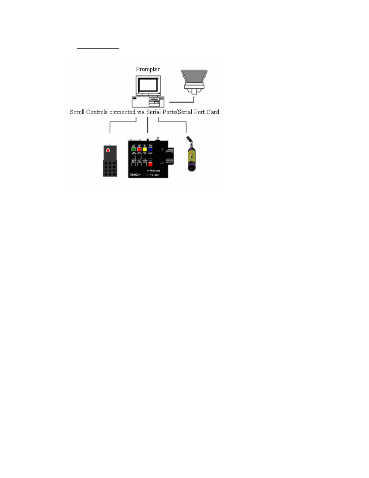
4. THEORY OF OPERATION
The VSB allows an unlimited* number of hand or foot controls to be connected to a
prompter machine to control the prompt output. Selection of the appropriate controller
is based on three methods. The three modes of operations are as follows:
(*-One COM port is required for each separate scroll control)
Mode A – Active Controller Wins:
In this mode the active scroll control must return the potentiometer to zero (counter
clockwise) and the other controller must advance the potentiometer. The VSB will
switch to the new controller. Control is maintained as long as the pot is not at the zero
position or as long as all the other controls have their pot at zero. To switch, it is
important that the controller giving up is returned to zero or switching will not occur.
Mode B – Last User Wins
In this mode, the VSB will switch anytime any potentiometer is adjusted, either up or
down. This mode has the advantage of working if a centre pot mode is selected. This
mode is more intuitive and does not require the controller giving up control to return
to the zero pot position, therefore hand and foot con trol combinations are best su it ed
for mode B operation.
Mode C – Fastest User Wins
The user with the potentiometer at the highest rate will have control the prompt
output.
Page 5
Virtual Spider Box Guide Page 5
5. VSB DIAGRAM
Page 6
Virtual Spider Box Guide Page 6
6. VSB CONFIGURATION
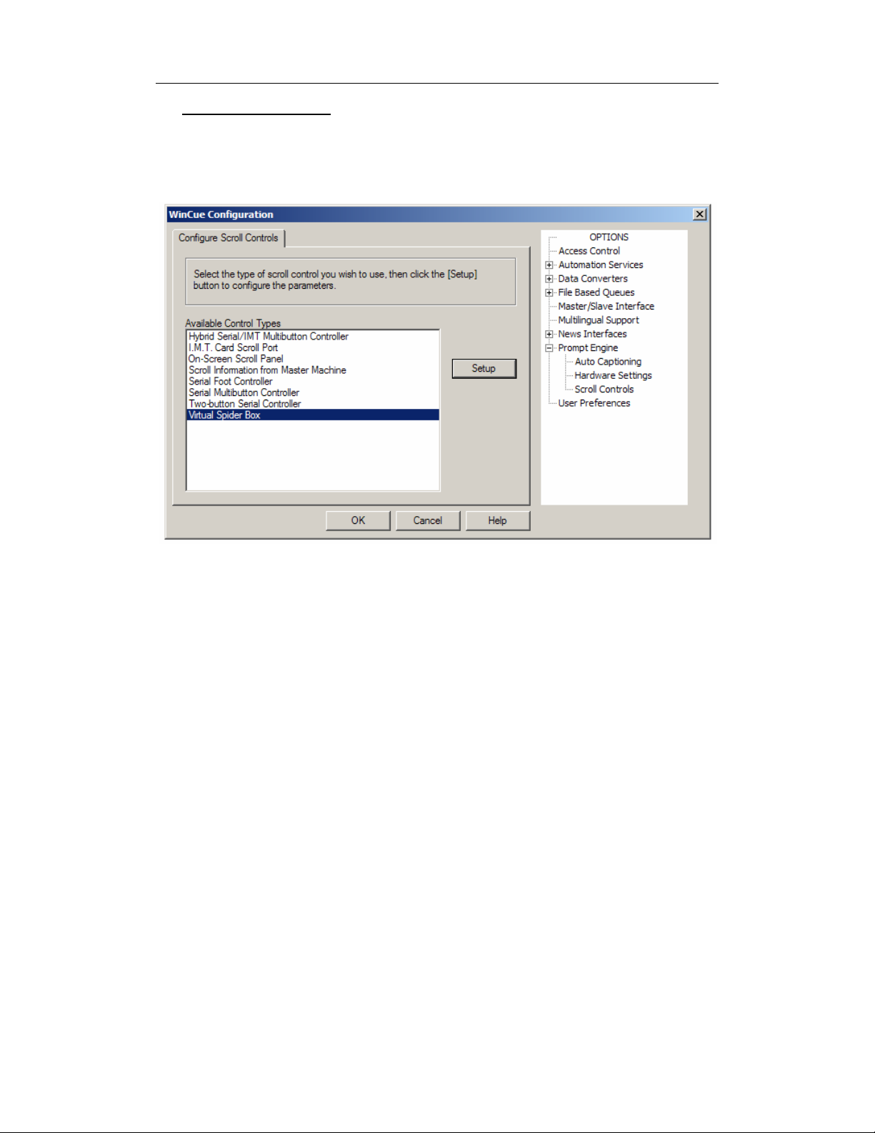
The VSB is configured in much the same way as existing scroll controls – via the
Client by selecting the ‘Tools | Options’ menu and the ‘Prompt Engine | Scroll
Controls’ property sheet (Figure 1)
The user must select the ‘Virtual Spider Box‘ and press the ‘Setup’ button to be able
to configure the Scroll Controls that are connected to the various Serial Ports.
Upon pressing the ‘Setup’ button the user will see the dialog shown in Figure 2
figure 1
Page 7
Virtual Spider Box Guide Page 7
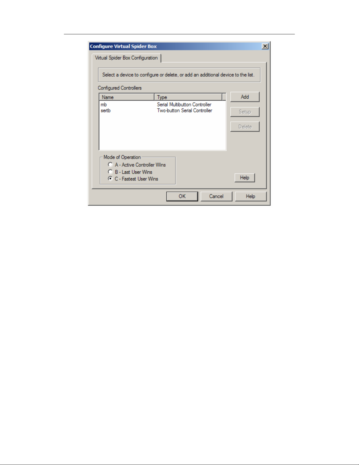
figure 2
Figure 2 shows the configuration dialog for the VSB where the user can add/remove
and configure the various supported Scroll Controls and select the scroll speed mode
of operation (see 4. Theory of Operation for details)
Page 8

Virtual Spider Box Guide Page 8
APPENDICES
Page 9
Virtual Spider Box Guide Page 9
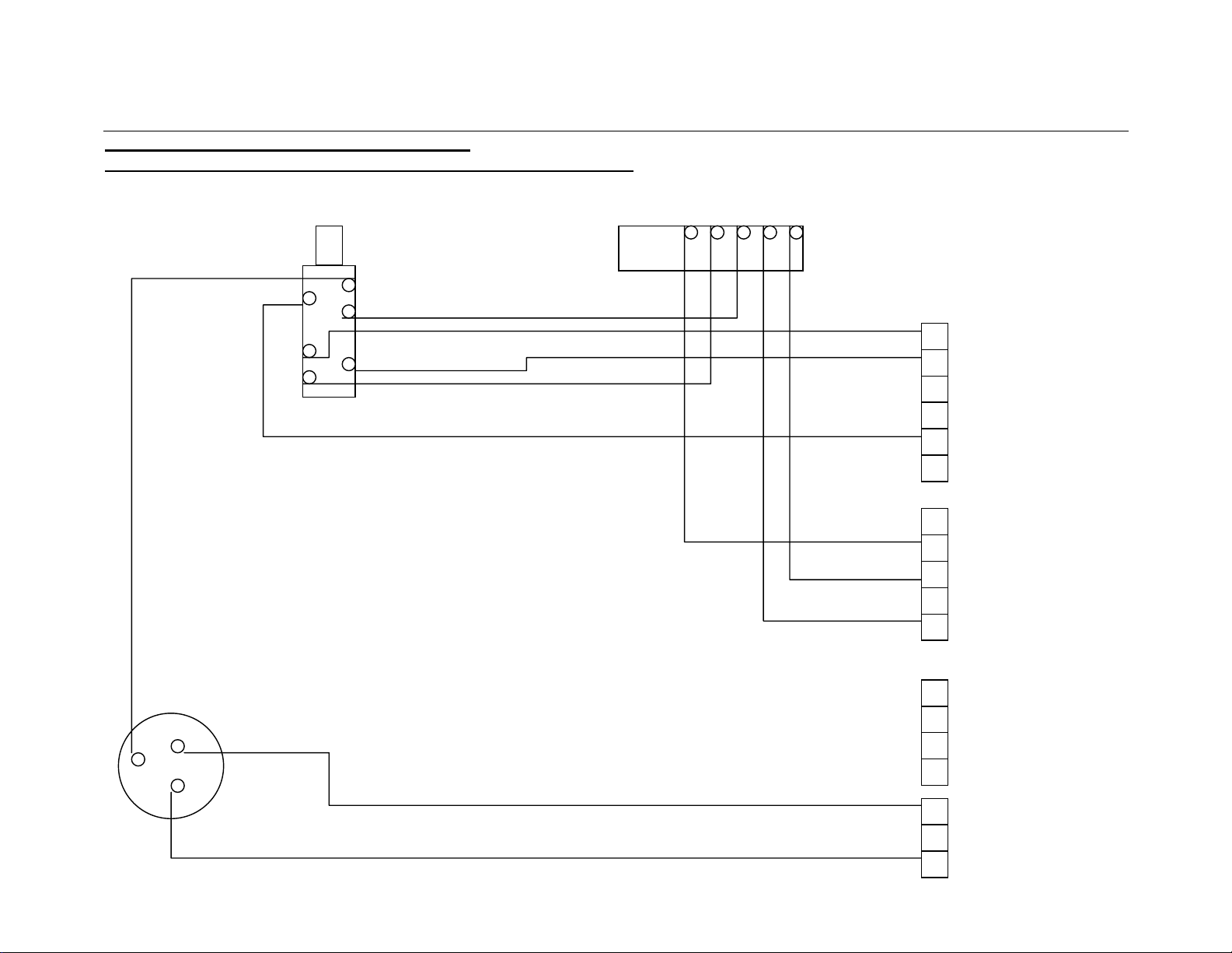
APPENDIX A. MULTIBUTTON WIRING DIAGRAMS
C
ONVERTING T HE HYBRID MULTIBUTTON INTO A SERIAL MULTIBUTTON
A 3way molex connector is required for J4, An extra wire is now required on pin 13 of the 15way D connector
13 12 11 10 9
Foot/ Hand switch Remote socket
Blue
Blue
Green
J1
Purple
Red
J2
Black
Scroll Pot White
Brown
Purple
J3 Yellow
Red
J4
Black
Page 10

Virtual Spider Box Guide Page 10
BACK VIEW OF THE MULTIBUTTON PCB 60-497-01
Link these pins together
J1
J2
J3
J4
Page 11
Virtual Spider Box Guide Page 11
APPENDIX B. FOOT CONTROL WIRING DIAGRAMS
F
OOT CONTROL CABLE MODIFICATIONS
Open the 15way D plug and perform the following modifications
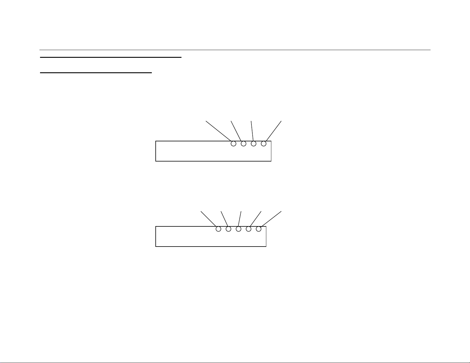
Blue Yellow Black Red/Green
Old wiring for 15way D
Green Blue Yellow Black Red
New wiring for 15way D
Yellow, Black, Red wires control the scroll control
Green, Blue wires control the Fwd/Rev button
Page 12

Virtual Spider Box Guide Page 12
MODIFICATION TO THE FOOT CONTROL
NOTE: This is only required if the foot control card has been manufactured in the USA before 2005.
This is NOT required if the card has been manufactured by Autocue (UK) and has the GEMINI label
Unscrew and remove the Green and Blue wires from the Fwd/Rev switch (cut and discard)
Cut the Blue and Green wires from the 6-way Molex connector
Now reconnect the Green and Blue wires that were on the 6-way Molex connector to the Fwd/Rev switch
Page 13

Virtual Spider Box Guide Page 13
END OF DOCUMENT
DELIBERATELY BLANK
 Loading...