

Page 1
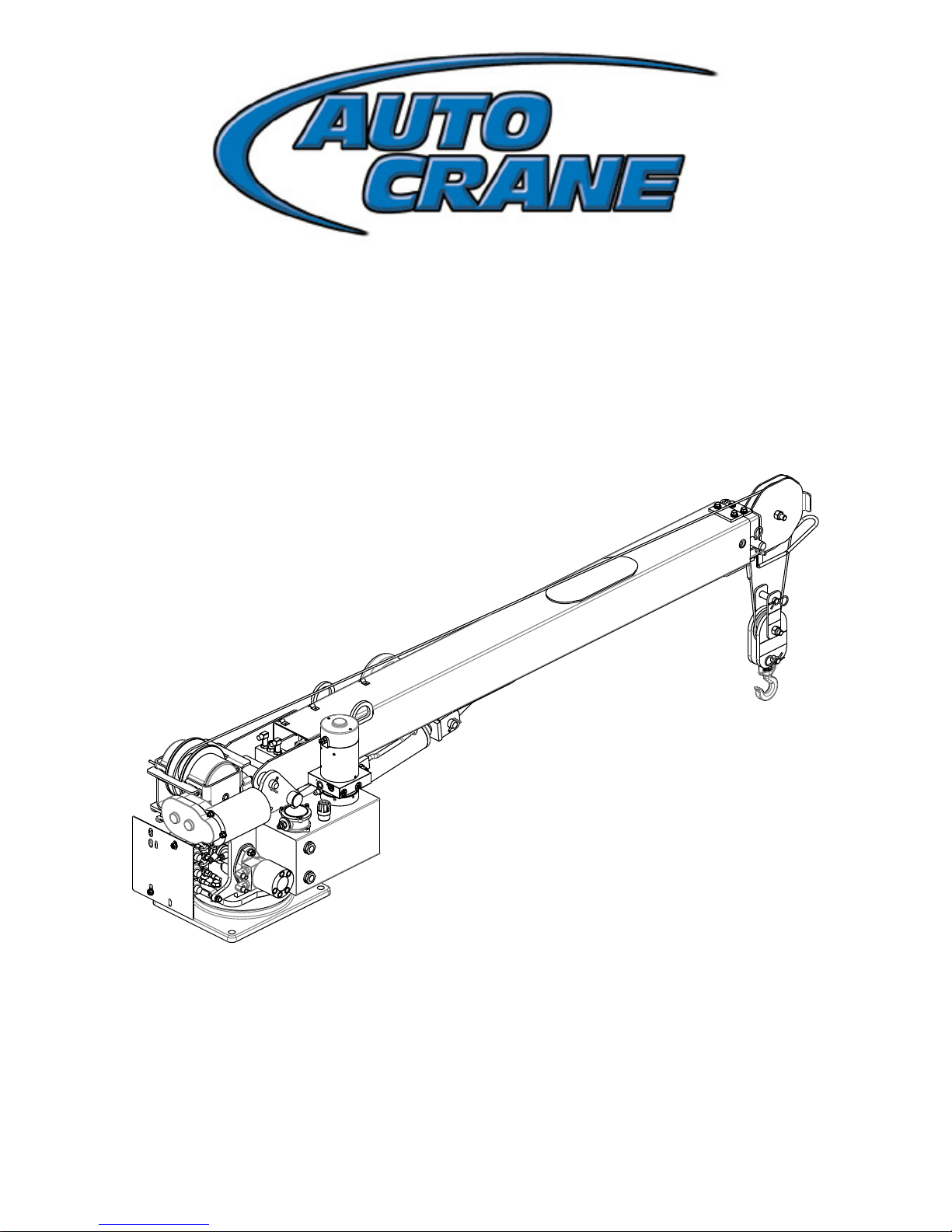
3203 PR/PRX/PRFX
O
WNERS MANU
AL
erial No. __________________
S
Mailing Address:
P.O. Box 580697 Tulsa,
OK 74158-0697 Physical
Address: 4707 N. Mingo
Rd. Tulsa, OK 74117-5904
Phone 1-800-777-2760
Fax (918) 269-6688
http://www.autocrane.com
OM-320950000-0-%
Page 2

Page 3
Product Registration Rev 05152014
Auto Crane Registration
From: Date:
End User Information:
Company: Phone:
Address:
City: State: Zip:
Contact: E-mail:
Distributor Information:
Company: Phone:
Address:
City: State: Zip:
Contact: E-mail:
Product Information:
Model No: Serial No: Date Delivered:
VIN #:
ONE REGISTRATION FORM PER UNIT (CRANE, BODY, OR COMPRESSOR)
Please submit form within 15 days after installation
Online:
www.autocrane.com | Resources | Warranties
Fax: 918-234-2177
Mail: Product Registration, Auto Crane Company, PO Box 580697, Tulsa, OK 74158-0697
Page 4

Page 5
WARNINGS
WARNING! Federal law (49 cfr part 571) requires that the Final Stage Manufacturer of a vehicle certify that
e
hicle complies with all applicable federal regulations. Any modifications performed on the vehicle
the v
prior to the final state are also considered intermediate stage manufacturing and must be certified as to
compliance. The installer of this crane and body is considered one of the manufacturers of the vehicle.
As such a manufacturer, the installer is responsible for compliance with all applicable federal and state
regulations, and is required to certify that the vehicle is in compliance.
WARNING! It is the further responsibility of the installer to comply with the OSHA Truck Crane Stability
Requirements as specified by 29 CFR part 1910.180 (C) (1).
WARNING! NEVER OPERATE THE CRANE NEAR ELECTRICAL POWER LINES!
Death or serious injury will result from boom, line, or load contacting electric lines. Do not use crane
within 10 feet (3.05m) of electric power lines carrying up to 50,000 volts. One-foot additional clearance
is required for every additional 30,000 volts or less. SEE DANGER DECAL (P/N 040529) in this Owner’s
Manual.
WARNING! NEVER .....................................................
♦ EXCEED load chart capacities (centerline of rotation to hoist hook).
♦ Un-reel last 5 wraps of cable from drum!
♦ Wrap cable around load!
♦ Attempt to lift or drag a load from the side! The boom can fail far below its rated capacity.
♦ Weld, modify, or use unauthorized components on any Auto Crane unit! This will void any warranty or
liability. Also failure of the crane may result.
♦ Place a chain link on the tip of the hook and try to lift a load!
♦ Use a sling bar or anything larger than the hook throat that could prevent the hook latch from closing,
thus negating the safety feature!
♦ Hold on any pendant Select Switch that will cause unsafe operating conditions!
WARNING! In using a hook with latch, ALWAYS make sure that the hook throat is closed before lifting
a load! Proper attention and common sense applied to the use of the hoist hook and various slings will
prevent possible damage to material being hoisted and may prevent injury to personnel.
WARNING! Failure to correctly plumb and wire crane can cause inadvertent operation and damage to
crane and/or personnel!
WARNING! Auto Crane Company remote controlled cranes are not designed or intended for use for any
applications involving the lifting or moving of personnel.
WARNING! ALWAYS operate the crane in compliance with the load capacity chart. DO NOT USE the
overload shutdown device to determine maximum rated loads, if the crane is equipped with this type of
device.
READ THIS PAGE
Page 6

Page 7

3203 PR/PRX/PRFX
TABLE O
INTRODUCTION ……………………………………………………………… 1
GENERAL SPECIFICATIONS ……………………………………………………………… 3
SAFETY TIPS AND PRECAUTIONS ……………………………………………………………… 4
OPERATING PRACTICES & WARNINGS ……………………………………………………………… 6
QUALIFICATIONS FOR OPERATORS ……………………………………………………………… 7
OPERATION OF UNIT / OUTRIGGERS ……………………………………………………………… 11
INSPECTION ……………………………………………………………… 12
TESTING ……………………………………………………………… 15
MAINTENANCE ………………………………………………
BATTERIES ……………………………………………………………… 18
LUBRICATION AND MAINTENANCE SCHEDULE ……………………………………………………………… 20
SINGLE LINE PROCEDURE ……………………………………………………………… 22
ROTATION BEARING REPLACEMENT ……………………………………………………………… 23
SAFETY DECAL SECTION ……………………………………………………………… 24
F CONTENTS
……………… 16
GENERAL DIMENSIONS ……………………………………………………………… 31
MOUNTING AND INSTALLATION ……………………………………………………………… 32
GENERAL ASSEMBLY, HARDWIRED ……………………………………………………………… 3
PEDESTAL ASSEMBLY ……………………………………………………………… 40
BOOM ASSEMBLY ……………………………………………………………… 52
HOIST ASSEMBLY ……………………………………………………………… 49
TRAVELING BLOCK ASSEMBLY ……………………………………………………………… 63
RELAY PANEL ASSEMBLY ……………………………………………………………… 65
ELECTRICAL SECTION, HARDWIRED ……………………………………………………………… 66
PENDANT ASSEMBLY ……………………………………………………………… 68
TWECO W/SWITCH MOUNT ……………………………………………………………… 71
HYDRAULIC SECTION ………………………………………………………
POWER UNIT ……………………………………………………………… 75
GENERAL ASSEMBLY, FM ……………………………………………………………… 76
FM CONTROL USE & CARE ……………………………………………………………… 82
TRANSMITTER ASSEMBLY, FM ……………………………………………………………… 83
……… 72
4
ELECTRICAL SECTION, FM ……………………………………………………………… 85
FM, DIAGNOSTICS, TROUBLESHOOTING, AND ID PROG. ……………………………………………………………… 86
LOAD CHART …………
CONVERSION TO SINGLE LINE ................................................................ 95
…………………………………………………… 94
Page 8

Page 9

3203PR/PRX
INT
Auto Crane products are designed to provide
n
y years of safe, trouble-free, dependable
ma
service when properly used and maintained.
To assist you in obtaining the best service
from your crane and to avoid untimely crane
and/or vehicle failure, this manual provides
the following operating and service instructions. It is specifically recommended that all
operating and service personnel consider this
manual as mandatory material for reading
and study before operating or servicing Auto
Crane products. It is highly recommended
that crane owners, equipment managers, and
supervisors also read this manual.
Auto Crane has incorporated several safety
features in the 3203 PR/PRX crane for your
protection.
For your convenience the overall dimensions
of the 3203 PR/PRX crane are included on the
General Dimension Drawing. Rotation and
turning radius are also listed on that drawing.
Remember, the crane adds weight to the vehicle.
Adding weight may change the driving and
riding characteristics of the vehicle unless the
appropriate overload spring(s) are installed
on the truck. The payload of the vehicle is
reduced by the weight of the crane. The operator
should exercise care when loading the vehicle.
Distributing the payload on the vehicle evenly
will greatly improve the driving and riding
characteristics of the vehicle.
Auto Crane Company issues a limited
warranty certificate with each unit sold.
See last page for warranty.
The 3203 PR/PRX cranes are attached to your
truck electrical system through the Main Power
Switch provided. The
3203 PR/PRX is another highly efficient
Auto Crane product. The use of a maintenancefree battery is not recommended on any Auto
Crane product. The recommended alternator
and battery
RODUCTION
that will give the longest life with the most useful
d
ty cycle is a 125-amp alternator with a 500 cold
u
cranking amp battery. These specifications should
be considered minimum.
It has always been Auto Crane Company policy
to handle all warranty claims we receive as
promptly as possible. If a warranty claim involves
discrepant material or workmanship, Auto
Crane will take immediate corrective action. It
is understandable that Auto Crane Company
cannot assume responsibility of liability when it
is obvious that our products have been abused,
misused, overloaded or otherwise damaged by
inexperienced persons trying to operate the
equipment without reading the manual.
Auto Crane will not assume responsibility
or liability for any modifications or changes
made to unit, or installation of component
parts without authorization.
Auto Crane maintains a strong distributor
network and a knowledgeable Customer Service
Department. In most cases, an equipment problem
is solved via phone conversation with our customer
service department. The customer service
department also has the ability to bring a local
distributor, a regional sales manager, or a factory
serviceman into the solution of an equipment
problem.
If, through no fault of Auto Crane Company,
it is necessary to send an experienced factory
serviceman on a field service call the rates stated in
the Auto Crane Distributor’s Flat Rate Manual will
apply.
Auto Crane Company’s extensive Research and
Development Program allow our customers
to use the best equipment on the market. Our
Engineering Staff and our knowledgeable sales
people are always available to our customers
in solving crane and winch-type application
problems. When in doubt, call the Auto Crane
factory.
Note: This manual should remain with the
crane at all times.
1
Page 10

3203PR/PRX
INT
DISTRIBUTOR ASSISTANCE :
S
uld you require any assistance not given in
ho
this manual, we recommend that you consult
your nearest Auto Crane Distributor. Our
distributors sell authorized parts and have
service departments that can solve almost any
needed repair. This manual does not cover all
maintenance, operating, or repair instructions
pertinent to all possible situations. If you require
additional information, please contact the Auto
Crane Company at the following telephone
number: (918) 836-0463. The information
contained in the manual is in effect at the time
of this printing. Auto Crane Company reserves
the right to update this material without notice
or obligation.
RODUCTION
2
Page 11
LIFTING CAPACITIES
Ō lbs Ō lbs
2 3,200 9 1,100
3 3,200 10 1,000
4 2,500 11 900
5 2,000 12 830
6 1,670 13 770
7 1,500 14 710
8 1,250 15 660
3203PR/PRX
GE
NERAL SPECIFICATIONS
DIMENS
id
W
Height: 24.00 in (0.61 m)
Length: 9 ft 1-1/2 in (2.78 m)
[boom(s) stored]
Weight: 860 lbs (390kg)
CAPACITY
IONS
th: 21 in (0.53 m)
10,000 ft-lbs (1.38
[ft-lbs = horizontal distance from centerline
of rotation to free hanging weight (feet) x
amount of weight (pounds)]
tt-m)
REACH
S
cond boom will reach from 7 feet 4
e
inches to 11 feet 4 inches.
Third boom will reach from 11 feet 4
inches to 15 feet 4 inches.
CABLE
62 ft (18.9) of 7/32 in (5.56 mm) di
aircraft quality cable. This cable has a single
line breaking strength of
5,600 lbs (2,540 kg).
ameter
CHASSIS REQUIREMENTS
201,600 in-lbs (22,777 N
8,800 LBS (3,992 kg.) GVWR minimum
m) RBR minimum
ELECTRICAL SYSTEM
REQUIREMENTS
ltage: 12 VDC
Vo
Alternator: 125 amp (minimum)
Battery: 130 minute reserve
capacity (minimum)
Maintenance type
ROTATION
360º Co
ntinuous
TANK OIL CAPACITY
2.4 GALLO
NS (9.08 LITERS)
3
Page 12

--
- IMPORTANT ---
SAFETY TIPS AND PRECAUTIONS
o unqualified or unauthorized person shall be
1. N
allowed to operate the crane.
e
2. WARNING: N
unauthorized components / parts on any Auto
Crane unit. This will void any warranty or
liability. Also, failure of the crane may result.
3.
ake certain the vehicle meets minimum chassis
M
requirements. (These requirements do not
guarantee unit stability.)
4. Make certain the crane is installed per factory
specifications. Contact your local distributor or the
Auto Crane factory if any questions arise.
5. Visual inspections and tests should be conducted at
the beginning of each shift each day to insure that
the crane and all its operating systems are in good
condition and working order before it is used.
6. Inspect hydraulic hoses frequently for signs of
deterioration, and replace them as required.
7. If a hydraulic break occurs, leave the area of the
break and do not attempt to stop the break by hand
as the hydraulic oil may be hot and under high
pressure which can cause serious injury. Shut the
system down as soon as possible.
8. Check the hook at least every thirty days for
distortions or cracks and replace it as required.
9. Oil gears as required.
10. Stop all operations when cleaning, adjusting or
lubricating the machine.
11. Keep dirt and grit out of moving parts by keeping
crane clean. Make sure machine is free of excess oil,
grease, mud and rubbish, thus reducing accidents
and fire hazards.
12. When a new cable is installed, operate first with a
light load to let the cable adjust itself.
13. Locate the vehicle at the work site for the best
stability possible.
14. Keep the vehicle in a level position while loading or
unloading.
15. Observe operating area for obstructions and/or
power lines that might be a hazard.
ver weld, modify, or use
16. WARNING: NEVER OPERATE THE CRANE
u
NEAR ELECTRICAL POWER LINES. A
Crane Company recommends that the crane
never be any closer to a power line (including
telephone lines) than 10 feet at any point.
l
ow the vehicle engine to warm up before
17. Al
operating crane.
18. Know the weight of your rigging and load to
avoid overloading the crane.
19. Deduct the weight of the load handling equipment
from the load rating to determine how much weight
can be lifted.
20. All load ratings are based on crane capacity, NOT
the vehicle stability. Remember in lifting a heavy
load, the weight can create enough tipping moment
to overturn the vehicle
21. Always comply with load chart capacities,
(centerline of rotation to hook).
22. Secure all loads before lifting.
23. Always set the emergency brake before
beginning operation.
24. Keep objects and personnel clear of crane path
during operation.
25. Operate control levers slowly and smoothly in
order to meter oil flow for safe operation. (Not
applicable to electric-hydraulic cranes.)
26. Always extend the outriggers from vehicle to the
ground before crane operation. Insure that they are
firmly positioned on solid footings. Stand
clear of outriggers while they are being extended.
27. If any outrigger, when extended, rests on a curb or
other object that prevents it from extending to its
maximum distance, shorten bearing or
fulcrum point and reduce the maximum load
accordingly.
28. When an outrigger will not reach the ground due to
holes or grades, it shall be blocked up to provide
level and firm support for the truck.
29. When working in soft earth, use wide pads
under outrigger feet to prevent sinking.
30. Always store outriggers before transportation.
to
WARNING!
Auto Crane Company cranes are not designed or intended for use in lifting or moving persons. Any such
use sha
ll be considered to be improper and the seller shall not be responsible for any claims arising there
from. This sale is made with the express understanding that there is no warranty that the goods shall be
fit for the purpose of lifting or moving persons or other improper use and there is no implied warranty or
responsibility for such purposes.
4
Page 13

--- IMPORTANT ---
SAF
31. Alway
32. Remember the overall height of the entire
33. Disengage power takeoff (PTO) before
34. Always walk around the vehicle before
35. Never drive with a load suspended from
36. Do not take your eyes off a moving load.
37. Never swing a load over people.
38. Do not stop the load sharply in midair so
39. Crane boom length should be kept as
40. Keep the load directly and vertically under
s store the crane in its stowed position for
transportation.
for garage door clearance or when
moving under objects with low overhead
clearance
moving the vehicle.
(Not applicable to electric-hydraulic cranes.)
moving.
crane.
Look in the direction you are moving.
that it swings like a pendulum. Meter the
control levers to avoid this situation.
(Not applicable to electric-hydraulic cranes.)
short as possible for maximum lifting
capacity and greater safety. Longer booms
require additional care in accelerating and
decelerating the swing motion, and thus
slow down the working cycle and reduce
productivity.
the boom point at all times. Crane booms
are designed to handle vertical loads, not
side lifts.
ETY TIPS AND PRECAUTIONS
unit
WARNING: Never attempt to lift, drag, tow or
pull a load from the side. The boom can fail
far below its rated capacity.
o no
41. D
42. Do not lift personnel with any wire rope
43. WARNING: In us
44. WARNING: Ne
45. WARNING: Ne
46. Do no
47. WARNING: Ne
t push down on anything with boom
extensions; similarly do not lift anything with
boom extensions.
attachment or hook. There is no implied
warranty or responsibility for such purposes.
ing a safety hook, ALWAYS
close the hook throat before lifting a load.
Proper attention and common sense applied
to the use of the hook and various slings will
prevent possible damage to material being
hoisted and may prevent injury to personnel.
ver place a chain link on the
tip of the hook and try to lift a load with the
hoist.
ver use a sling bar or
anything larger than the hook throat which
could prevent the safety latch from closing,
thus negating the safety feature.
t wrap the wire rope around sharp
objects when using winch.
ver unreel last 5 wraps of
cable from drum.
5
Page 14

--- IMPORTANT ---
OP
ERATING PRACTICES AND WARNINGS
ake certain the vehicle meets minimum chassis
1. M
requirements. (These requirements do not
guarantee unit stability)
2. Make certain the crane is installed per factory
specifications. Contact your local Distributor or the Auto
Crane factory if any questions arise.
3. Keep the vehicle in as level a position as possible while
loading or unloading.
4. ALWAYS set the vehicle emergency brake before
beginning crane operations.
5. ALWAYS use outriggers from vehicle to the ground during
crane operation. Make sure they are firmly positioned on
solid footings.
6. All load ratings are based on crane capacity, NOT truck/
crane stability.
7. Keep objects and personnel clear of crane path
during operation.
8. Keep hoist cable pulled tight at all times.
9. REMEMBER, in lifting a heavy load, the weight can
create enough tipping momentum to overturn the
vehicle.
10. ALWAYS keep load as close to ground as
possible.
11. Hydraulic hoses need to be inspected frequently for signs
of deterioration, and be replaced as required.
12. The hoist hook is an important item that an operator
should consider and use properly. It should be
checked on a daily basis for distortion or cracks.
13. ALWAYS store outriggers before road travel.
ARNING! NEVER OPERATE THE CRANE NEAR
14. W
E
LECTRICAL POWER LINES! Death or serious injury
will result from boom, line, or load contacting electric
lines. Do not use crane within
10 feet (3.05m) of electric power lines carrying up to
50,000 volts. One foot additional clearance is required
for every additional 30,000 volts or less.
15. WARNING! NEVER EXCEED load chart
capacities (centerline of rotation to hoist hook).
16. WARNING! NEVER un-reel last 5 wraps of cable
from drum!
17. WARNING! NEVER wrap cable around load!
18. WARNING! NEVER attempt to lift or drag a load
from the side! The boom can fail far below its
rated capacity.
19. WARNING! NEVER weld, modify, or use
unauthorized components on any Auto Crane unit!
This will void any warranty or liability. Also failure of
the crane may result.
20. WARNING! NEVER place a chain link on the tip of the
hook and try to lift a load!
21. WARNING! NEVER use a sling bar or anything larger
than the hook throat that could prevent the hook latch
from closing, thus negating the safety feature!
22. WARNING! In using a hook with latch, ALWAYS insure
that the hook throat is closed before lifting
a load! Proper attention and common sense applied
to the use of the hoist hook and various slings will
prevent possible damage to material being hoisted
and may prevent injury to
personnel.
WARNING! NEVER hold any Control Select Switch
on that will cause unsafe operating conditions!
WARNING!
ut
o Crane Company remote controlled, stiff boom cranes are not designed or
A
intended for use on any applications involving the lifting or moving of personnel.
6
Page 15

QUALIFICATIONS FOR AND CONDUCT OF
OP
ERATORS AND OPERATING PRACTICES
REFERENCE A
O
ERATORS
P
1. C
rane operation shall be limited to personnel
ith the following minimum qualifications:
w
A. Designated persons.
B. Trainees under the direct supervision of a
designated person.
C. Maintenance and test personnel (when it is
necessary in the performance of their duties).
D. Inspectors (crane).
2. No one other than the personnel specified above
shall enter the operating area of a crane with the
exception of persons such as oilers, supervisors, and
those specified persons authorized by supervisors
whose duties require them to do so and then only
in the performance of their duties and with the
knowledge of the operator or other persons.
SME B30.5a AND OSHA 1910.180 FOR COMPLETE QUALIFICATION
QUALIFICATIONS FOR OPERATORS
erators shall be required by the employer to pass
1. Op
a practical operating examination. Qualifications
shall be limited to the specific type of equipment for
which examined.
2. Operators and operator trainees shall meet the
following physical qualifications:
A. Vision of at least 20/30 Snellen in one eye and
20/50 in the other, with or without corrective
lenses.
B. Ability to distinguish colors, regardless of
position, if color differentiation is required for
operation.
C. Adequate hearing with or without hearing aid
for the specific operation.
3. Evidence of physical defects or emotional
instability, which render a hazard to operator or
others, which in the opinion of the examiner could
interfere with the operator’s performance, may be
sufficient cause for disqualification. In such cases,
specialized clinical or medical judgment and tests
may be required.
4. Evidence that operator is subject to seizures or loss
of physical control shall be sufficient reason for
disqualification. Specialized medical
REQUIREMENTS
tests may be required to determine these conditions.
5. Operators and operator trainees should have normal
depth perception, coordination, and no tendencies to
dizziness or similar undesirable characteristics.
6. In addition to the above listed requirements, the
operator shall:
A. Demonstrate the ability to comprehend and
B. Posses the knowledge of emergency procedures
C. Demonstrate to the employer the ability to
D. Be familiar with the applicable safety regulations.
E. Understand the operating procedures as outlined
F. Be thoroughly familiar with the crane and its
G. Understand the operating procedures as outlined
CONDUCT OF OPERATORS
1. The o
will divert his attention while actually operating the
crane.
2. Each operator shall be responsible for those operations
under the operator’s direct control. Whenever there is
any doubt as to safety, the operator shall consult with
the supervisor before handling the loads.
3. The operator should not leave a suspended load
unattended unless specific precautions have been
instituted and are in place.
4. If there is a warning sign on the switch or engine
starting controls, the operator shall not close the switch
or start the engine until the warning sign has been
removed by the appointed person.
5. Before closing the switch or starting the engine, the
operator shall see that all controls are in the “OFF”
interpret all labels, operator’s manuals, safety
codes, and other information pertinent to correct
crane operations.
and implement it.
operate the specific type of equipment.
by the manufacturer.
control functions.
by the manufacturer.
perator shall not engage in any practice, which
7
Page 16

QUALIFICATIONS FOR AND CONDUCT OF
OP
ERATORS AND OPERATING PRACTICES
or neutral position and all personnel are in the clear.
6.
f power fails during operation, the operator shall:
I
A. Move power controls to the “OFF” or neutral
position.
B. Land the suspended load and boom, if practical.
7. The operator shall be familiar with the
equipment and its proper care. If adjustments or
repairs are necessary, the operator shall report the
same promptly to the appointed person, and shall
also notify the next operator.
8. The operator at the start of each shift shall test all
controls. If any controls do not operate properly, they
shall be adjusted or repaired before operations are
begun.
9. Stabilizers shall be visible to the operator while
extending or setting unless a signal person assists
operator.
OPERATING PRACTICES/HANDLING THE
LOAD
ize of load.
1. S
A. No crane shall be loaded beyond the rated load
except for test purposes.
B. The load to be lifted is to be within the rated load
of the crane and its existing configuration.
C. When loads that are not accurately known are
to be lifted, the person responsible for the job
shall ascertain that the weight of the load does
not exceed the crane rated load at the radius at
which the load is to be lifted.
2. Attaching the load.
A. The load shall be attached to the hook by means
of slings or other devices of sufficient capacity.
B. Hoist rope shall not be wrapped around the load.
3. Moving the load.
The operator shall determine that:
A. The crane is level and, where necessary, the
vehicle/carrier is blocked properly.
B. The load is well secured and balanced in the
sling or lifting device before it is lifted more
than a few inches.
C. Means are provided to hold the vehicle
stationary while operating the crane.
D. Before starting to lift, the hook shall be
positioned over the load in such a manner as to
minimize swinging.
E. During lifting care shall be taken that:
1. There is no sudden acceleration or
deceleration of the moving load.
2. Load, boom or other parts of the crane do
not contact any obstruction.
F. Cranes shall not be used for dragging loads
sideways.
G. This standard recognizes that telescopic boom
cranes are designed and intended for handling
materials. They do not meet personnel lift or
elevator requirements. Therefore, no lifting,
lowering, swinging or traveling shall be done
while a person is on the hook or load. Hook
attached suspended work platforms (baskets)
shall not be used with cranes covered by this
standard. Crane manufacturer must approve
work platforms attached to the boom.
H. The operator should avoid carrying loads over
people.
I. When the crane is so equipped, the
stabilizers shall be fully extended and set.
Blocking under stabilizers shall meet the
requirements as follows:
1. Strong enough to prevent crushing.
2. Of such thickness, width and length as
to completely support the stabilizer pad.
J. Firm footing under all tires, or individual
stabilizer pads should be level. Where such
a footing is not otherwise supplied, timbers,
cribbing, or other structural members to
distribute the load so as to not exceed allowable
bearing capacity or the underlying material
should provide it.
K. In transit, the boom shall be carried in stowed
position.
L. When rotating the crane, sudden starts and
stops shall be avoided. Rotational speed
shall be such that the load does not swing
out beyond the radius at which it can be
controlled.
M. The crane shall not be transported with a
load on the hook unless recommended by the
manufacturer.
8
Page 17

QUALIFICATIONS FOR AND CONDUCT OF
OP
ERATORS AND OPERATING PRACTICES
o person should be permitted to stand or
N. N
pass under a suspended load.
4. Stowing procedure.
Follow the manufacturer’s procedure and sequence
when stowing and un-stowing the crane.
MISCELLANEOUS
P
ERATING NEAR ELECTRICAL POWER
O
LINES
3. Caution shall be exercised when working near overhead
lines, because they can move horizontally or vertically
due to wind, moving the danger zone to new positions.
4. In transit with no load and boom lowered the clearance
shall be specified in Table 1.
5. A qualified signalperson shall be assigned to observe
the clearance and give warning before approaching the
above limits.
A. Any overhead wire shall be considered to be an
energized line unless and until the person owning
such line or the electrical utility authorities verify
that it is not an energized line.
B. Exceptions to this procedure are allowed, if approved
by the administrative or regulatory authority
provided the alternate procedure insures equivalent
protection and is set forth in writing.
C. Durable signs shall be installed at the operator’s
station and on the outside of the crane, warning that
electrocution or serious bodily injury may
occur unless a minimum clearance of 10 ft.
(3.0m) between the crane or the load being handled
and energized power lines. Greater clearances are
required because of higher voltage as stated above.
These signs shall be revised but not removed when
local jurisdiction requires greater clearances.
1. Cranes shall be operated so that no part of the crane
r load enters into the danger zone shown above.
o
EXCEPTIONS
A. The danger zone may be entered after
nfirmation by an appointed person that the
co
electrical distribution and transmission lines
have been de-energized and visibly grounded at
the point of work; or
B. The danger zone may be entered if insulating
barriers (not a part of nor an attachment to the
crane) have been erected to prevent physical
contact with the lines.
2. For lines rated 50 kV or below, minimum clearance
between the lines and any part of the crane or load
(including handling appendages) shall be 10-ft. (3m).
For higher voltages, see Table 1.
BLE 1
TA
minimum required
__clearance____
__
normal voltage, kV
phase to phase) ft (m)
(
when operating near high voltage power lines
over to 50 10 (3.50)
er 50 to 200 15 (4.6)
ov
over 200 to 350 20 (6.1)
over 350 to 500 25 (7.62)
over 500 to 750 35 (10.67)
over 750 to 1000 45 (13.72)
while in transit with no load and boom lowered
ov e r to 0.75 4 ( 1 . 2 2 )
ov er 0.75 t o 50 6 (1.83)
ov e r 50 to 345 10 (3.83)
ov e r 345 to 750 16 (4.87)
over 750 to 1000 20 (6.1)
9
Page 18
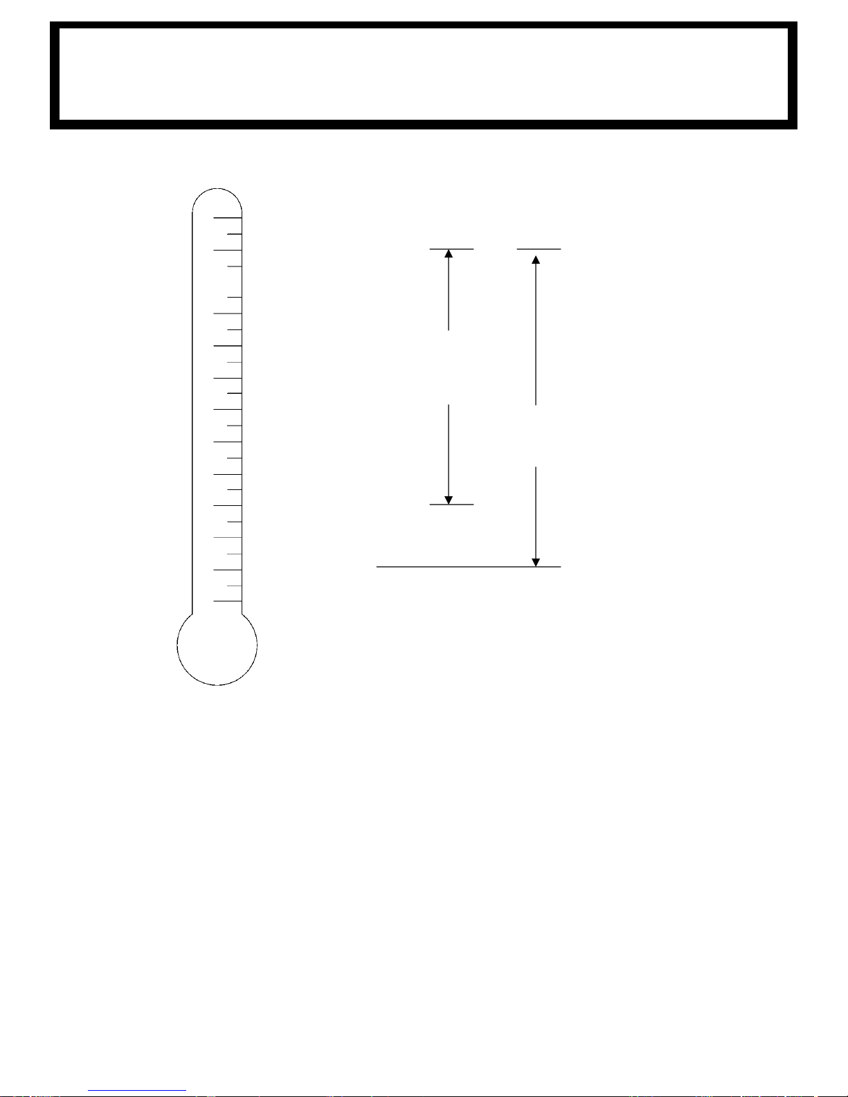
RANGE - SMALL EH CRANES
RECO
MMENDED OPERATING TEMPERATURE
OIL TEMPERATURE
200° F (93.3°C)
180° F (82.2°C)
160° F (71.1° C)
140° F (60° C)
120° F (48.9°C)
100° F (37.8°C)
80° F (26.7° C)
60° F (15.6° C)
40° F (4.4°C)
20° F (-6.6°C)
0° F (-17.8 C)
-20° F (-28.9° C)
-40° F (-40°C)
5W20 ANTI-WEAR
AULIC OIL OR
HYDR
EQUIVALENT
HySyn ISO32 SYNTHETIC
HYDRAULIC OIL OR
EQUIVALENT
NOTES
1. In applications where low oil temperatures may exist (below -20°F), an ex ternal
heating system may be required.
2. A symptom of excessively low temperatures is hydraulic motor operation but
no fluid flow from tank.
CAUTION! HYDRAULIC RESERVOIR OIL TEMPERATURE MUST NOT EX CEED
180°F OR DAMAGE TO CRANE MAY OCCUR. THIS MAY AFFECT
CRANE WARRANTY
10
Page 19

--- IMPORTANT ---
OP
ERATION OF UNIT
ake sure this manual has been thoroughly read
1. M
by all crane operating personnel and supervisors.
2. A routine inspection of the crane should be
mandatory before each operating day. Any defects
should be corrected immediately.
3. At a job site the vehicle should be positioned so that the
crane can adequately reach the load within the rated
capacity (centerline of rotation to hoist hook).
4. Keep the vehicle as level as possible during
operation.
5. For electric cranes, engage emergency brake and leave
ignition on with transmission in neutral (or in
park for automatic transmissions). Activate any crane
power switches. For Auto Crane units requiring
battery and hydraulic operation, engage emergency
brake, place gear selector in neutral, press clutch,
activate PTO, release clutch and, after hydraulic fluid is
warm, set throttle control to proper engine speed.
6. Always use outriggers from the truck to the ground.
Be sure these are firm and adequately positioned. When
rotating, keep load as low to the ground as possible.
7. Remove the transmitter from cab or storage area.
Power transmitter on. Detach hook from dead man.
Crane is now ready for operation.
OPERATION OF
8. Always boom up before rotating so the boom will clear
the required boom support.
9. When extending the boom, always maintain
clearance between the boom crown and the
traveling block or hoist hook.
10. Always observe safe and practical operation to
avoid possible accidents. Refer to Safety Tips and
Precautions.
11. After completing lifting operations, return the
boom to stowed position on the boom support.
Avoid unneeded pressure on the boom support.
12. Store transmitter in proper location (in cab or
storage area).
13. Return outriggers to stowed position. Make sure
they are pinned in place or jacklegs are returned to
compartment.
14. Check work area for any tools or equipment not stored.
15. Release throttle control, depress clutch and
disengage PTO. Deactivate any crane power switches.
16. Report any unusual occurrence during crane
operation that may indicate required maintenance or
repair.
17. NEVER use two cranes to support a load too large
for either crane.
HYDRAULIC OUTRIGGERS
1. Shift crane/outrigger control valve to
utrigger” position.
“o
2. Operate the outrigger control valves to
position the outriggers.
3. After outriggers are positioned, return
crane/outrigger selector to “crane”
position.
4. Crane is now ready to operate.
OU
TRIGGERS
MANUAL OUTRIGGERS
1. Pull lock pins to release jackleg or drop
wn outrigger and move to outermost lock
do
position.
2. Make sure lock pins are reinstalled
properly.
3. Lower outrigger pad to firm ground and
adjust foot to take out slack.
4. Crane is now ready to operate.
11
Page 20
INSPECTION
RE
QUIREMENTS
REFERENCE A
P
ECTION CLASSIFICATION
INS
1.
nitial inspection.
I
Prior to initial use, all new, altered, modified or
extensively repaired cranes shall be inspected by a
designated person to insure compliance with provisions
of this standard.
2. Regular inspection.
Inspection procedure for cranes in regular service is
divided into two general classifications based upon
the intervals at which inspection should be performed.
The intervals in turn are dependent upon the nature
of the components of the crane and the degree of their
exposure to wear, deterioration, or malfunction. The
two general classifications are herein designated as
“frequent” and “periodic” with respective intervals
between inspections as defined below.
A. Frequent inspection - daily or before each use
B. Periodic inspection - one to twelve-month
intervals or as specifically recommended by the
manufacturer or qualified person.
DESIGNATED PERSONNEL SHALL
RFORM INSPECTIONS ONLY.
PE
SME B30.5a AND OSHA 1910.180 FOR COMPLETE INSPECTION REQUIREMENTS
FREQUENT INSPECTION
pections should also occur during operation for
Ins
any deficiencies that might appear between regular
inspections. Any deficiencies, such as those listed below,
shall be carefully examined and a determination made as
to whether they constitute a hazard:
1. Inspect control mechanisms for maladjustment that
interferes with proper operation.
2. Inspect control mechanisms for excessive wear of
components and contamination by lubricants or other
foreign matter.
3. Inspect safety devices for malfunction.
4. Visually inspect all hydraulic hoses, particularly
those that flex in normal operation of crane functions.
5. Inspect hooks and latches for deformation, chemical
damage, cracks, and wear. Refer to ANSI/ASME B30.10.
6. Inspect for proper rope reeving.
7. Inspect electrical wiring and components for
malfunctioning, signs of excessive deterioration, dirt
and moisture accumulation.
8. Inspect hydraulic system for proper oil level and leaks.
9. Inspect tires for recommended inflation pressure, cuts
and loose wheel nuts.
10. Inspect connecting pins and locking device for wear
damage and loose retaining bolts.
11. Inspect rope for gross damage, such as listed below,
which may be an immediate hazard.
A. Distortion such as kinking, crushing, un stranding,
birdcaging, main strand displacement, or core
protrusion. Loss of rope diameter in a short length or
unevenness of outer strands should be replaced.
B. General corrosion.
C. Broken or cut strands.
D. Use care when inspecting sections of rapid
deterioration around flange points, crossover points,
and repetitive pickup points on drums.
E. Inspect number, distribution, and type of visible
broken wires. Reference Rope Maintenance section
in the owner’s manual.
Continued use of rope depends upon good
judgment by a designated person in evaluating
remaining strength in a used rope after allowance
for deterioration disclosed by inspection. Continued
rope operation depends upon this remaining
strength.
12
Page 21

INSPECTION
RE
QUIREMENTS
ODIC INSPECTION
PERI
Any deficiencies, such as those listed below, shall be
c
refully examined and determination made as to
a
whether they constitute a hazard:
1. Inspect for deformed, cracked or corroded members in
the crane structure and entire boom.
2. Inspect for loose bolts, particularly mounting bolts.
3. Inspect for cracked or worn sheaves and drums.
4. Inspect for worn, cracked, or distorted parts such
as pins, bearings, shafts, gears, rollers and devices.
5. Inspect for excessive wear on brake and clutch system
parts and lining.
6. Inspect crane hooks for cracks.
7. Inspect travel steering, braking, and locking devices
for malfunction.
8. Inspect for excessively worn or damaged tires.
9. Inspect hydraulic hose, fittings, and tubing for the
following problems:
A. Evidence of leakage at the surface of the flexible
hose or its junction with metal and coupling.
B. Blistering, or abnormal deformation to the outer
covering of the hydraulic or pneumatic hose.
C. Leakage at threaded or clamped joints that
cannot be eliminated by normal tightening or
recommended procedures.
D. Evidence of excessive abrasion or scrubbing on
the outer surface of a hose, rigid tube, or fitting.
Means shall be taken to eliminate the interference
of elements in contact or otherwise protect the
components.
10. Inspect hydraulic pumps and motors for the following
problems:
A. Loose bolts and fasteners.
B. Leaks at joints between sections.
C. Shaft seal leaks.
D. Unusual noises or vibrations.
E. Loss of operating speed.
F. Excessive heating of the fluid.
G. Loss of pressure.
11. Inspect hydraulic valves for the following problems:
A. Cracks in valve housing.
B. Improper return of spool to neutral position.
C. Leaks at spools or joints.
D. Sticking spools.
E. Failure of relief valves to attain or maintain
correct pressure setting.
F. Relief valve pressure shall be checked as specified by the
manufacturers.
12. Inspect hydraulic cylinders for the following problems:
A. Drifting caused by fluid leaking across piston.
B. Rod seals leaking.
C. Leaks at welding joints.
D. Scored, nicked, or dented cylinder rods.
E. Damaged case (barrel).
F. Loose or deformed rod eyes or connecting joints.
13. Inspect hydraulic filters for evidence of rubber particles
on the filter elements indicating possible hose, O ring,
or other rubber component deterioration. Metal chips or
pieces on the filter
may denote failure in pumps, motors, or cylinders.
Further inspection will be necessary to determine
the origin of the problem before corrective action
can be taken.
14. Inspect labels to confirm correct location and legibility.
Reference decal layout in this manual for proper location
of decals.
15. Rope Inspections need not be at equal calendar intervals and
should be more frequent as the rope approaches the end of
useful life.
A qualified person shall inspect the wire rope based
on such factors as:
A. Expected rope life as determined by experience on the
particular installation or similar installations.
B. Severity of environment.
C. Percentage of capacity lifts.
D. Frequency rates of operation.
E. Exposure to shock loads.
This inspection shall cover the entire length of the
rope. Only the surface wires need to be inspected and
no attempt should be made to open the rope. Any
deterioration resulting in appreciable loss of original
strength shall be noted and determination made as to
whether use of the rope would constitute a hazard. A few
notable deterioration points are listed below:
13
Page 22

INSPECTION
RE
QUIREMENTS
eduction of rope diameter below nominal
A. R
diameter due to loss of core support.
B. Internal or external corrosion.
C. Wear of outside wires.
D. Severely corroded, cracked, bent, worn, or
improperly applied connections.
CRANES NOT IN REGULAR USE
ne, which has been idle for a period of over one
A cra
month or more, shall be given an inspection conforming
to the “initial” and “regular” inspection requirements of
this section.
INSPECTION RECORDS
ted records of periodic inspection should be made
Da
on critical items such as brakes, crane hooks, rope,
cylinders, and relief pressure valves.
14
Page 23

TESTING
RE
QUIREMENTS
REFERENCE A
TESTING SHALL BE PERFORMED BY DESIGNATED PERSONNEL ONLY.
ri
or to initial use, all new, altered, modified, or extensively repaired cranes shall be tested for compliance with
P
the operational requirements of this crane.
Test requirements:
1. Test all functions to verify speed and operation.
2. Check that all safety devices are working properly.
3. Confirm operating controls comply with appropriate function labels.
4. Test loads shall not exceed 110% of the manufacturer’s load rating.
5. Written reports shall be maintained showing test procedures and confirming the adequacy of repairs.
SME B30.5a AND OSHA 1910.180 FOR COMPLETE TESTING REQUIREMENTS
15
Page 24

GENERAL
RE
PAIRS AND MAINTENANCE
REFERENCE A
SME B30.5a AND OSHA 1910.180 FOR COMPLETE MAINTENANCE AND REPAIR
REQUIREMENTS
A preventative maintenance program should be
ta
blished based on this section and all replacement
es
parts should be obtained from AutoCrane Company. For
replacement parts contact your local authorized distributor.
MAINTENANCE PRECAUTIONS
lace crane where it will cause the least interference
1. P
with other equipment or operations.
2. Verify all controls are in the “off” position and all
operating features secured from inadvertent motion by
brakes, pawls, or other means.
3. The means for starting the crane shall be rendered
inoperative.
4. The boom should be secured in place before
maintenance.
5. Relieve hydraulic oil pressure from all hydraulic circuits
before loosening or removing hydraulic components.
6. Warning or “OUT OF ORDER” signs shall be placed on
all crane controls.
7. After adjustments and repairs have been made,
the crane shall not be returned to service until all
guards have been reinstalled, trapped air removed
from hydraulic system (if required), safety devices
reactivated, and maintenance equipment removed.
ADJUSTMENTS AND REPAIRS
ny hazardous conditions disclosed by the inspection
1. A
requirements shall be corrected before operation of
crane is resumed. Only designated personnel shall do
adjustments and repairs.
2. Adjustments shall be maintained to assure correct
functioning of components, the following are
examples:
A. Functional operating mechanism.
B. Safety devices.
C. Control systems.
3. Repairs or replacements shall be provided as needed
for operation, the following are examples:
A. Critical parts of functional operating mechanisms
which are cracked, broken, corroded, bent, or
excessively worn.
B. Critical parts of the crane structure which are
cracked, bent, broken, or excessively corroded.
C. Crane hooks showing cracks, damage, or corrosion
shall be taken out of service. Repairs by welding are
not recommended.
4. If bleeding the hydraulic system is required, run each
crane function until smooth operation of that particular
function is noticeable.
LUBRICATION
ving parts of the crane, for which lubrication
All mo
is specified, should be regularly lubricated per the
manufacturer’s recommendations and procedures.
Reference Lubrication and Maintenance Schedule in this
manual.
ROPE REPLACEMENT
precise rules can be given for determination of the exact
No
time for replacement of rope, since many variable factors are
involved.
1. Conditions such as the following shall be reason for
questioning continued use of the rope or increasing the
frequency of inspection:
A. In running ropes, six randomly distributed broken
wires in one lay or three broken wires in one strand
in one lay.
B. One outer wire broken at the contact point with the
core of the rope structure and protrudes or loops
out of the rope structure. Additional
inspection of this section is required.
C. Wear of one third of the original diameter of the
outside individual wire.
D. Kinking, crushing, bird caging, or any other
damage resulting in distortion of the rope
structure.
E. Evidence of any heat damage from any cause. F.
Reduction from nominal diameter of more than
1/64 in. (0.4mm) for diameters up to and including
5/16 in. (8 mm), 1/32 in. (0.8 mm) for diameter 3/8
in. (9.5 mm) to and including 1/2 in. (13 mm), 3/64
in. (1.2 mm) for diameter 9/16 in. (14.5 mm) to
and including 3/4 in. (19
mm). 1/16 in. (1.6 mm) for diameter 7/8 in. (22
mm) to and including 11/8 in. (29 mm), 3/32 in.
16
Page 25

GENERAL
RE
PAIRS AND MAINTENANCE
(2.4 mm) fo
including 11/2 in. (38 mm).
G. In standing ropes, more than two broken wires in
one lay in sections beyond end connections or more
than one broken wire at an end
connection.
2. Replacement rope shall have a strength rating at least as
great as the original rope furnished or recommended
by AutoCrane. A rope manufacturer, AutoCrane, or a
qualified person shall specify any deviation from the
original size, grade, or construction.
r diameters 11/4 in. (32 mm) to and
ROPE MAINTENANCE
ope should be stored to prevent damage or
1. R
deterioration.
2. Unreeling or uncoiling of rope shall be done as
recommended by the rope manufacturer and with
care to avoid kinking or inducing twist.
3. Before cutting a rope, seizing shall be placed on each
side of the place where the rope is to be cut
to prevent unlaying of the strands. On pre-formed
rope, one seizing on each side of the cut is required.
On non-preformed ropes of 7/8 in. (22
mm) diameter or smaller, two seizings on each
side of the cut are required, and for non-preformed
rope 1 in. (25 mm) diameter or larger, three seizings on
each side of the cut are required.
4. During installation care should be exercised to avoid
dragging of the rope in the dirt or around objects that
will scrape, nick crush or induce sharp bends in it.
5. Rope should be maintained in a well-lubricated
condition. It is important that lubricant applied as a
part of a maintenance program shall be compatible
with the original lubricant and to this end the rope
manufacturer should be consulted. Lubricant applied
shall be the type that does not hinder visual inspection.
Those sections of rope that are located over sheaves or
otherwise hidden during inspection and maintenance
procedures require special attention when lubricating
rope. The object of rope lubrication is to reduce
internal friction and to prevent corrosion.
6. When an operating rope shows greater wear or well-
defined localized areas than on the remainder of the
rope, rope life can be extended in some cases by shifting
the wear to different areas of the rope.
17
Page 26

MAINTENANCE
OF
BATTERIES
intenance of Auto Crane unit batteries differs very
Ma
little from the generally prescribed maintenance of any
lead acid battery. All batteries must be kept properly
charged, properly filled with water, and relatively clean.
Keep Properly Charged
a
ny things affect the proper charge to a battery,
M
as:
1. Regulator settings.
2. Proper tightness of belts on the alternator or
generator.
3. Good, clean connections of all cables and wires at the
following places:
such
deterioration of the remaining parts of the
battery.
Keep A Relatively Clean Battery
The b
ttery should be kept clean. Batteries filled
a
with
acid and which are not in use self-discharge to
a limited degree because of the nature of the materials
within the battery. If dirt is allowed to collect on the
top of the battery (and this dirt absorbs moisture)
and electrical path can be set up between the various
terminals of the battery and the ground. Once such a
path has been established, the self discharge of the battery
is accelerated. This also accelerates corrosion of the
battery cables at the terminals.
a. Battery.
b. Regulator.
c. Starting motor.
d. Alternator or generator.
e. Ground connections (most important).
It is of extreme importance to keep the battery as
fully charged as possible without overcharging,
especially when vehicles are left outside for extended
periods in extremely cold climates. A battery can
freeze. Freezing points for various specific gravities
of acid are as follows:
Specific Gravity Freezing Temp.
(Corrected to 80ºF) Degrees F.
1.280 -90ºF
1.250 -62ºF
1.200 -16ºF
1.150 5ºF
1.100 19ºF
As shown, a half-charged battery (about 1.100
specific
gravity) cannot stand for any length of time at 20ºF or it
will freeze.
The main reason for keeping the battery as fully
charged as possible without over-charging is to insure
that power is available even though the vehicle has been
standing for some time.
Periodic Maintenance is Needed
finite program of periodic maintenance of all
A de
batteries should be conducted on a regular basis.
Periodic maintenance includes:
1. Checking belts for tightness on the charging
equipment.
2. Checking battery electrolyte levels.
3. Checking cables for good connections.
4. Cleaning where corrosion is apparent.
When corrosion is cleaned off, the cable terminals
and
battery terminals should be coated with a light
coating of petroleum jelly before they are replaced.
When terminals are cleaned, the top of the battery
should be cleaned with a mild solution of soda water.
Low Maintenance Batteries
(Maintenance Free)
Low maintenance batteries should not be used on
toCrane Cranes or trucks equipped with AutoCrane
Au
Cranes. The batteries are not
designed for “deep” discharge.
Testing Your Battery
Keep Properly Filled with Water
The battery should always be p
roperly filled with water.
If the electrolyte level is allowed to fall below the top of
the plates, the results become threefold:
1. The exposed portion of the plate will become
sulfated.
2. The portion of the plate exposed is not usable.
3. That portion of the acid remaining becomes
more concentrated and may cause more rapid
ondition of the battery is in question, it should
If the c
removed from the vehicle, taken to the shop, and
allowed to reach room temperature. It should then
be recharged until specific gravity readings taken at
one-half hour intervals. If the specific gravity readings
are fairly uniform, the battery should be checked with
a high rate tester. Use the tester in accordance with the
manufacturer’s instructions. The high rate tester is the
best method to test a questionable battery.
18
be
Page 27

MAINTENANCE
OF
BATTERIES
, after charging, it is noted that the specific gravity
If
reading of one cell is 30 points less than any of the other
cells, it may be assumed that the cell is bad
and that the battery should be replaced. If all cells are
uniform but not up to full charge, a low rate of charge
should be attempted for an extended time. This usually
will recover a badly sulfated battery.
Replacing a Battery
t is necessary to replace a battery, and a dry
If i
charge battery is used, the following procedure
applies:
1. Fill the battery with electrolyte of the proper
specific gravity.
2. Place the battery on charge according to the
manufacturer’s instructions.
It is essential that the second step above be followed
to ensure that the battery going on the vehicle is fully
charged.
It is also very important that the battery hold-downs
checked periodically to insure that the batteries
are properly positioned to avoid vibration problems,
breakage of cables or terminals. Care must be taken
to avoid cracking or breaking containers or covers by
tightening hold-down fixtures excessively. They also
must not be so loose that breakage results from a holddown that is too loose.
be
19
Page 28
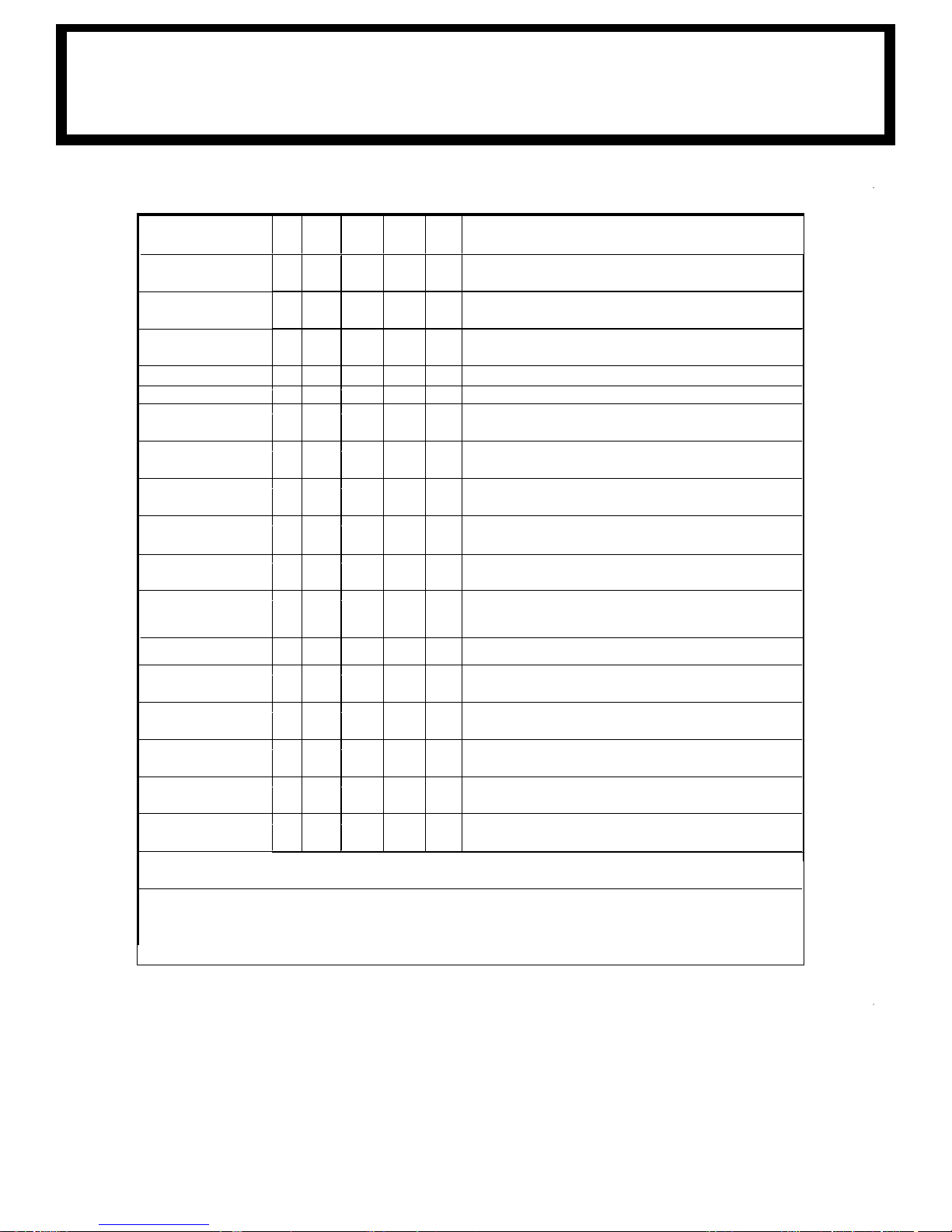
SERVICE
PERFORMED
DAY WKLY 3 MOS 6 MOS YEAR NOTES
LOAD HOOK X
CABLE DRUM X
HOIST / BOOM
CABLE
HYD. HOSES
HYD. FLUID
MOTOR
CO
NNECTIONS
POWER CABLE
PIN RETAINING
BOLTS
MOUNTING BOLTS X
ROTATION RING
GEAR
SHEAVE
BEARINGS
ALL OTHER BOLTS X
LIFT CYLINDER
BEARINGS
ROTATION
BEARING
ROTATION
BEARING BOLTS
ROTATION WORM
BEARING
HY
DRAULIC FLUID X
BOOM SLIDE
PADS
FOR ADDITIONAL
INFORMATION
SEE:
1) OWNER’S MANUAL
2) OSHA SECTION 1910.180
3) ANSI B30.5-1989
INSPECT HOOK & LATCH FOR DEFORMATION,
CRACKS, & CORROSION
MAKE SURE CABLE IS WOUND EVENLY ON
DRUM
NEKORB & ,SKNIK ,GNINETTALF ROF KCEHCX
STRANDS, SEE MANUAL
NOITCEPSNI LAUSIVX
LEVEL DIULF KCEHCX
X CH
ECK TERMINALS FOR TIGHT CONNECTIONS
X
CHECK INSULATION FOR DAMAGE OR
DETERIORATION
X
CHECK TORQUE TO 23 FT-LBS (GRADE 5), 35 FT-
LBS (GRADE 8) AS REQUIRED
CHECK TORQUE TO 335 FT-LBS FOR 3/4-16
X
LUBE WITH MOBILETAC LL, OR LUBRIPLATE P/N
15263, OR EQUAL
X
SEALED BEARING, REPLACE IF ROUGH OR
LOOS
E
CHECK TIGHTEN AS REQUIRED
X GREASE WITH MOBILEPLEX EP-2 OR
EQUIVALENT @ ZERKS
X GREASE WITH MOBILEPLEX EP-2 OR
EQUIVALENT @ ZERKS
X CHECK TORQUE TO 170 FT-LBS (HEX HEAD)
X GREASE WITH MOBILEPLEX EP-2 OR
EQUIVALENT @ ZERKS
DRAIN, FLUSH, AND REFILL
WITH MOBILE
DTE 13 HYD. OIL
PADS GREASED WHEN REPLACED
1) OWNER’S MANUAL
2) OSHA SECTION 1910.180
3) ANSI B30.5-1989
CAUTION: Routine maintenance insures trouble-free operation and
protects your investment. All warranties are void if maintenance is neglected.
3203PR/PRX
LUB
RICATION & MAINTENANCE SCHEDULE
20
Page 29

3203PR/PRX
LUB
TES:
NO
U
se only authorized parts. Any damage or malfunction caused by the use of unauthorized parts is not
1.
covered by Warranty or Product Liability.
2. Once a bolt has been torqued to its rated capacity and then removed; the bolt should be replaced with a
new one.
3. Auto Crane Company recommends that this crane be serviced per “Crane Inspection Log” P/N
999978. These logs should be filled in at the intervals noted and kept as a permanent record.
Additional copies are available from your local distributor.
RICATION & MAINTENANCE SCHEDULE
21
Page 30

CONVERTING FOR SINGLE LINE TO
DOUBLE LINE ON 3203EH CRANES
This procedure gives step by step directions for taking a double line and converting to a single line. Keep
in mind when using a single line, the max capacity drops from 3200lbs to 1600lbs.
1. Remove hook from traveling block by removing pin
Figure 1
2. Remove traveling block from rope
3. Disconnect the rope from the crown by removing pin.
4. Pivot single line bars 180 degrees then attach hook to the bars using the pin removed in step 1
5. Attach the rope to the traveling block side plates using the pin removed in step 3. Reference
pictures below for proper configuration.
Remove this pin
Remove this pin
Attach Rope Here
Single Line Bars
3203EH SINGLE LINE PROCEDURE
22
Page 31

3203PR/PRX/PRFX
BRA
KE ADJUSTMENT
ADJUS
The oil-cooled, fully adjustable, automatic safety brake operates in the worm housing lubricant, all
p
can be adjusted as follows:
If the brake does not respond to adjustment then a new leaf spring and brake disc is needed.
A torque wrench can be equipped with a special adapter to fit the input shaft (worm) of the winch.
The adapter can be made by welding a nut to the end of a piece of tubing as shown in the following
figure.
TING OIL COOLED WORM BRAKE
a
rt being submerged in oil. When the brake wears to the point that the load begins to drift, the brake
1. Loosen the lock nut on the adjusting screw.
2. Tighten the brake by turning the adjusting screw clockwise.
CAUTION:
use overheating, and damage to the brake parts. Tighten the lock nut after adjustment is
ca
completed.
Only ¼ turn is usually required to adjust the brake. Over-tightening can
er welding the cap and nut to the tubing, slot the tubing as shown. This will allow the special
Aft
adapter to slide over the keyway and then act as a large socket. A torque wrench can then be used to
apply the proper torque. Turn the torque wrench so that the drum turns in the spool out direction or
lowering direction. The torque ratings should be between 12-16 ft-lbs.
If the torque wrench does not show the proper value as it turns, then the worm brake adjusting bolt
should be turned clockwise ¼ turn. Each time the adjusting bolt is turned, check the torque reading.
Continue this procedure until the proper torque reading is achieved. Then tighten the lock nut.
23
Page 32
ROTATION BEARING REPLACEMENT
GUIDELINES-2003-4004
l bearings can wear over time. This includes the ma
Al
rules can be given for replacement of the rotation bearing, since many factors are in volved. However,
there are common symptoms seen during crane operation that may be caused by rotation bearing
wear. These symptoms include:
1. Excessive Noise
2. Rough rotation
3. Increased drive power required to rotate.
4. Metal particles in grease
REASONS FOR ROTATION BEARING REPLACEMENT
Any noticeable cracking in the bearing housing
1.
2. Excessive axial play (reference axial play check instructions below)
WARNING! NEVER TRY TO REPAIR A ROTATION BEARING. FOR A REPLACE MENT
BEARING CONTACT YOUR LOCAL AUTHORIZED DISTRIBUTOR.
AXIAL PLAY ALLOWANCE CHECK PROCEDURE
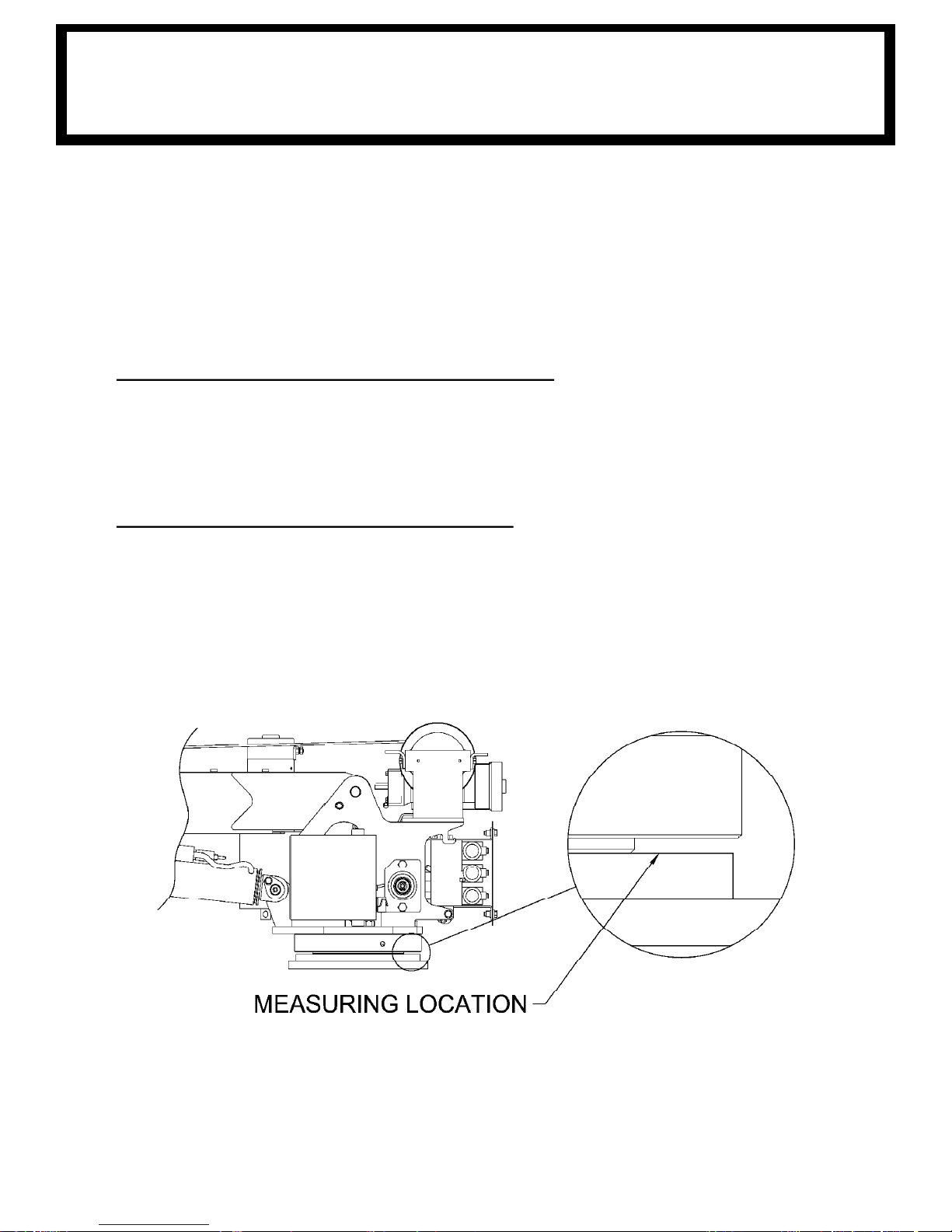
Boom up to the max boom angle and measure the clearance between base plate and the rotation
1.
bearing with a dial or filler gauge. Reference figure 1 for location.
2. Boom down to the horizontal position and measure the clearance between the base plate and the
rotation bearing with a dial indicator or feeler gauge. Reference figure 1 for loca tion.
3. If the difference between the two measurements exceeds 1.5mm, replace bearing.
4. Rotate crane 45 degrees then repeat steps above until you reach 360 degrees of rotation.
in rotation bearing on the crane. No pre cise
Rotation bearing replacement kit part number is 320878010
WARNING! WHEN REPLACING ROTATION BEARING, USE NEW HARDWARE WHICH IS
INCLUDED IN THE KIT ABOVE.
24
Page 33
3203PR/PRX
SAF
ETY DECAL SECTION
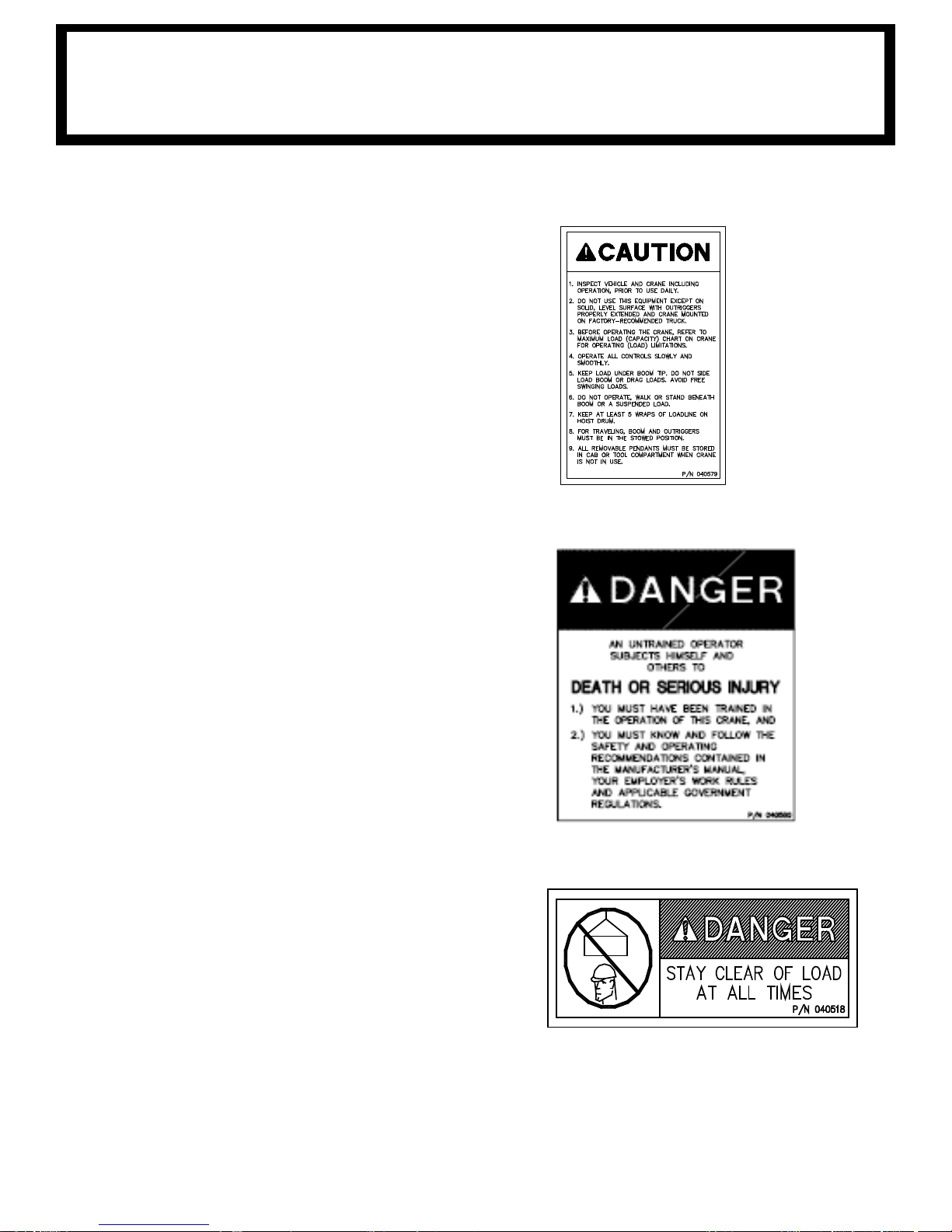
T NO.: 040579000
PAR
DECAL: OPERATING INSTRUCTIONS
FUNCTION: To inform the operator of the proper
procedure to follow for safe operation of
the crane.
USED ON: All Cranes
QUANTITY: 1
PLACEMENT: Right side plate
T NO.: 040580000
PAR
DECAL: OPERATING TRAINING
FUNCTION: To inform the operator of the need to
receive proper training before using
the crane.
USED ON: All Cranes
QUANTITY: 1
PLACEMENT: Right side plate
PART NO.: 040632000
DECAL: TAMPERING WITH OVERLOAD DEVICE
FUNCTION: To inform the operator that tamperating
w
it
h the overload device may cause a unit
failure or possible personal injury.
USED ON: All Cranes equiped with a load sensor
QUANTITY: 1
PLACEMENT: Right side of valve sensor.
25
Page 34
3203PR/PRX
SAF
ETY DECAL SECTION
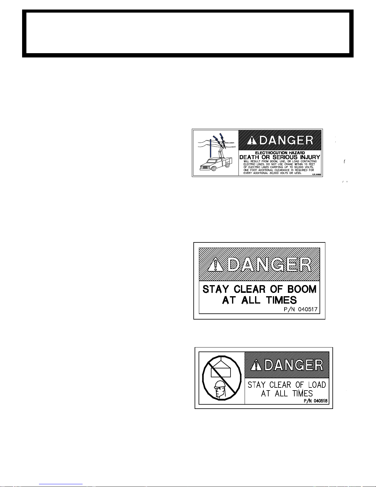
T NO.: 040529000
PAR
DECAL: ELECTROCUTION HAZARD
FUNCTION: To inform the operator of the
hazard involved with contacting
electrical power lines with crane
boom.
USED ON: All Cranes
QUANTITY: 2
PLACEMENT: Both sides of end of lower boom
PART NO.: 040517000
DECAL: STAY CLEAR OF BOOM
FUNCTION: To inform the operator of the
hazard of proximity or contact
with the crane boom during
operation.
USED ON: All Cranes
QUANTITY: 2
PLACEMENT: Both sides of crown
PART NO.: 040518000
DECAL: STAY CLEAR OF LOAD
FUNCTION: To inform the operator of the
hazard of proximity or contact
with the crane load during
operation.
USED ON: All Cranes
QUANTITY: 2
PLACEMENT: Both sides of traveling block
26
Page 35
3203PR/PRX
SAF
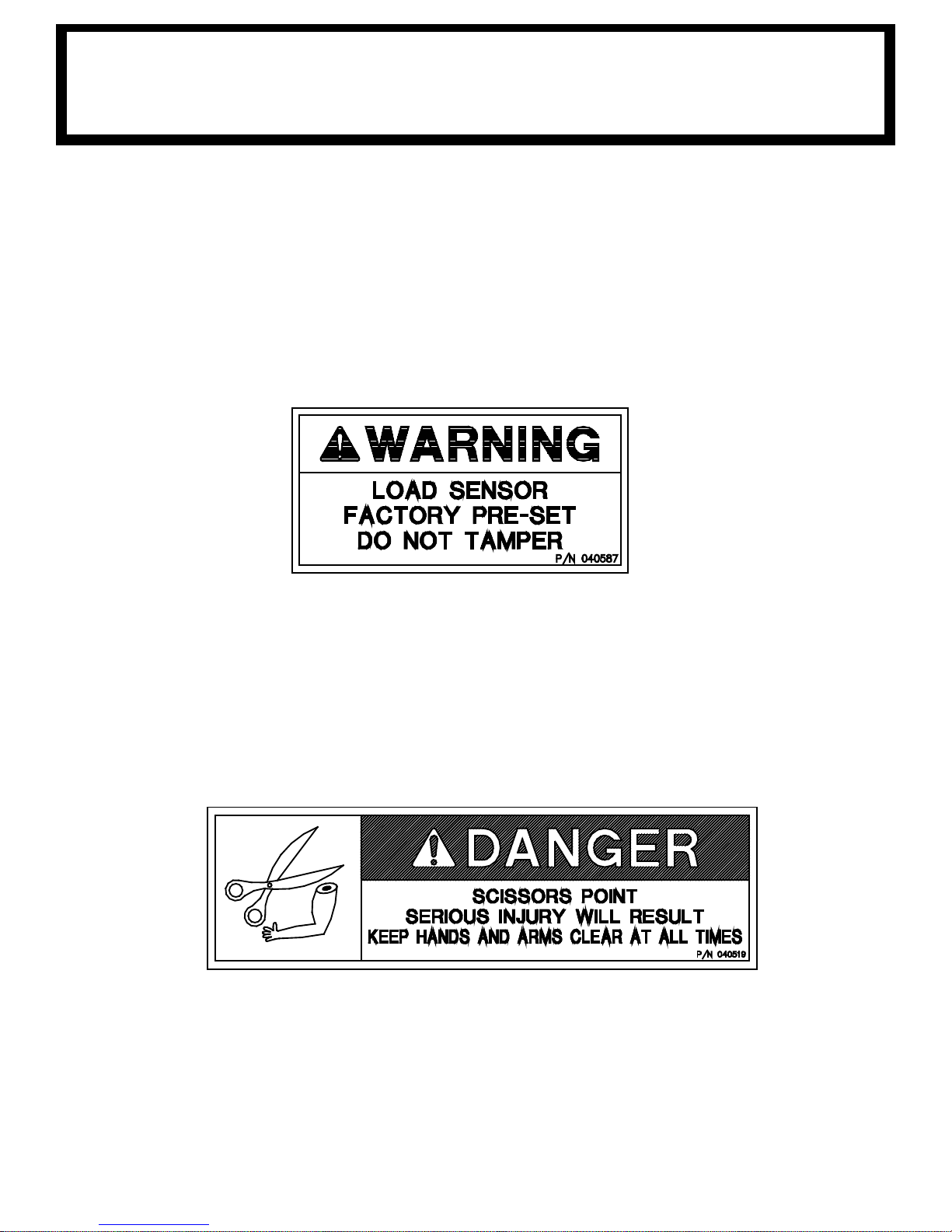
T NO.: 040587000 USED ON: All cranes equipped with a load
PAR
DECAL: LOAD SENSOR, DON’T TAMPER
FUNCTION: To inform the operator that the load
sensor is pre-set and that tampering
with the sensor may cause potentially
hazardous situation.
ETY DECAL SECTION
sensor.
QUANTITY: 2
PLACEMENT: Both sides of the lift cylinder near
the load sensor
PART NO.: 040519000 USED ON: All cranes.
DECAL: SCISSORS POINT QUANTITY: 2
FUNCTION: To inform the operator of possible
danger at scissors point on crane.
PLACEMENT: Both sides of the lift cylinder
27
Page 36

REMOTE CONTROL SAFETY PRECAUTIONS
READ THE OPERATOR'S MANUAL before using the Remote Control System.
Failur
e to follow the safety precautions may result in equipment failure or serious
personal injury.
MAKE SURE MACHINERY AND SUROUNDING AREA IS CLEAR BEFORE
OPERATING REMOTE CONTROL SYSTEM. Do not activate the Remote Control
System unless it is safe to do so.
TURN OFF THE RECEIVER POWER BEFORE WORKI
NG ON THE MACHINE.
Always disconnect the Remote Control System before doing any maintenance to
prevent accidental operation of the machine.
DO NOT MODIFY EQUIPMENT WITHOUT WRITTEN APPROVAL FROM THE
MANUFACTURER.
CARE
KEEP DRY. Do not clean the Transmitter / Receiver under high pressure. If water
or
other liquids get inside the Transmitter battery or Receiver compartment,
immediately dry the unit.
Remove the case and let the unit air dry.
Clean the unit after operation using a damp cloth to remove any mud, dirt, concrete,
etc. from the unit and prevent clogging of buttons, switches, etc.
MAINTENANCE / WELDING
DISCONNECT THE RECEIVER BEFORE WELDING ON THIS MACNINE. Failure
to di
sconnect will result in the destruction of the Receiver.
WARNING
3203PR/PRX
SAF
T NO.: 460169000 USED ON: All Cranes equiped with FM
PAR
ETY DECAL SECTION
controls.
DECAL: REMOTE CONTROL QUANTITY: 1
FUNCTION: To inform the operator of failure to
PLACEMENT: FRONT OF POWER UNIT
follow the saftey precautions may result
in equipment failure or serious personal
injury.
28
Page 37
1
3
4
6
5
7
8
9
10
14
16
11
3
1
4
12
14
16
17
FRONT OF
RESERVOIR
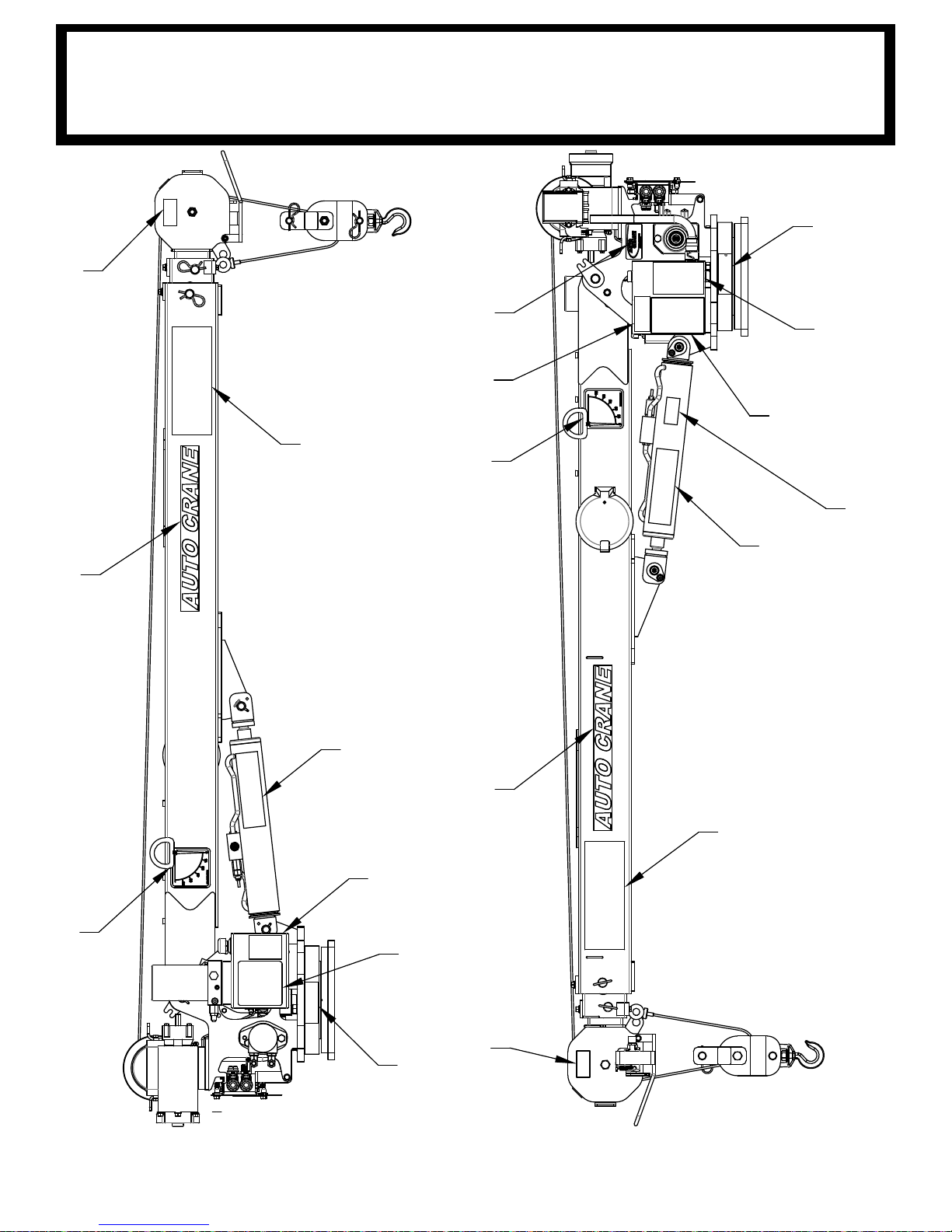
3203PR/PRX DECAL LAYOUT
P/
N: 320988004
29
Page 38

13
2
ITEM NO. QTY PART NUMBER DESCRIPTION
1 2 040517000 DECAL STAY CLEAR OF BOOM
2 2 040518000 DECAL STAY CLEAR OF LOAD
3 2 040519000 DECAL DANGER SCISSOR POINT
4 2 040529000
DECAL DANGER "ELECTROCUTION HAZARD" POWER LINE
5 1 040579000 DECAL OPERATION INSTRUCTIONS
6 1 040580000 DECAL TRAINED OPERATOR
7 1 040587000 DECAL WARNING LOAD SENSOR
8 1 330622000 DECAL SERIAL NO
9 1 40619001 DECAL AUTO CRANE LOGO
10 1 320318000 DECAL ANGLE INDICATOR CS
11 1 320318001 DECAL ANGLE INDICATOR SS
12 1 320988005 DECAL 3203 LOAD CHART
13 2 320433100 DECAL, TRAVELING BLOCK 3203
14 2 320918000 DECAL 3203 HORIZONTAL
15 1 360034000 DECAL AUTO CRANE LOGO
16 2 600047000 DECAL AUTO CR
ANE
17 1 460169000 DECAL WARNING, REMOTE CONTROL
18 1 040632000 DECAL WARNING - OVERLOAD
19 1 040824000
DECAL, AMERICAN FLAG, MADE IN THE U.S.A.
15
19
NEXT TO SWITCH
3203PR/PRX DECAL LAYOUT
P/N
: 320988004
30
Page 39

14 3/8" 7'-4 1/4"
15'-4/14"
19 3/4"
11 5/8"
19 1/8"
9'-1 5/8"
9"
13 1/8"
C
L
C
L
9"
Ø 9"
11 1/2"13 1/2"
14 3/4"
16 3/4"
1"
1"
Ø 7/8"
SERIAL NUMBER
SERIAL NUMBER
R16 3/4"
3203PR/PRX
GE
NERAL DIMENSIONS
31
Page 40
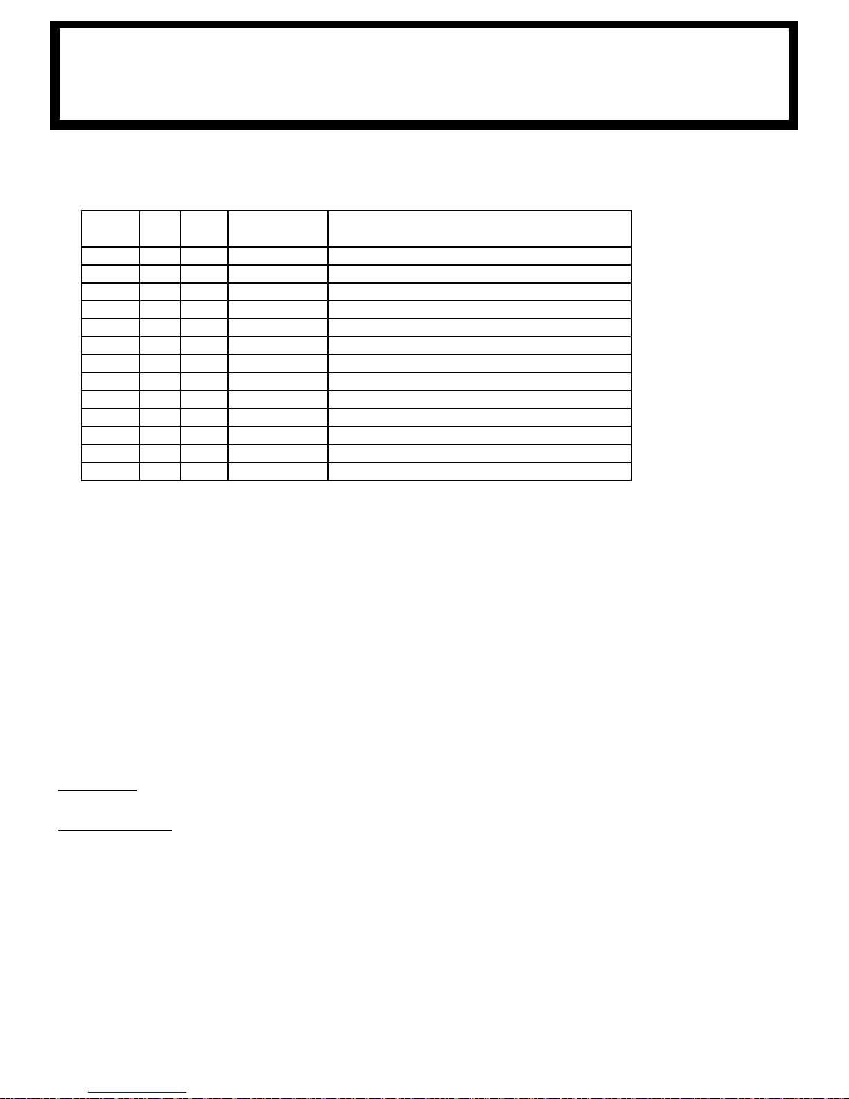
ITEM
QTY
FM
QTY
HW
PART NO DESCRIPTION
1 1 1 320433000 TRAVELING BLOCK ASSY
2 6 6 083800000 CLIP, CABLE 3838 (FRAME)
3 4 4 404226000 SCREW, HS HD,, 3/4 - 16UNF X 3" LG GRADE 8
4 4 4 404227000 NUT HX 3/4 - 16 UNF
5 4 022101000 WASHER, SP. LK 3/4
6 8 4 022102000 WASHER FL 3/4
7 1 1 320950000 OWNER'S MANUAL (3203 PR/PRX/PRFX)
8 1 1 404223020 COND ASSY 4 GA X 48" BLK
9 1 1 404223010 CABLE PWR, 25 FT
10 1 460157000 TRANSMITTER
11 1 460159000 TETHER CABLE, TRANSMITTER
12 1 1 40
4218000 TWECO CABLE ASSY W/MASTER SWITCH
13 1 680179000 PENDANT ASSY
3203PR/PRX
MO
heck to make sure the following items are with your crane.
1. C
UNTING AND INSTALLATION
2. Vehicle should meet minimum GVW rating of 8,800pounds. (does not include bodies or acce-
ries)
sso
3. Make sure mounting surface is properly reinforced to withstand 12,000 -lb capacity loading of
crane and that outriggers are used to provide total stability for the truck.
4. A 9” dia. hole should be cut out of mounting location (centered with mounting bolts) for access.
Reference general dimensions for bolt pattern.
5. Make sure the mounting bolts are 3/4”-16UNF, grade 8UNF. Torque bolts to 335 -lbs (dry).
6. When crane is not in operation, a boom support should always be used. Traveling block should
be connected to hook loop.
7. See the following page for installation.
8. See the following pages for additional electrical installation.
9. Load test the crane to ensure proper functioning and truck stability
10. Make certain the owner’s manual is delivered to the customer.
11. For additional help: call the service department at the Auto Crane Company. (918) 836-0463
(Tulsa,Oklahoma)
WARNING
FEDERAL LAW (49 CFR PART 571) REQUIRES THAT THE FINAL STAGE MANUFACTURER OF A
VEHICLE CERTIFY THAT HE VEHICLE COMPLIES WITH ALL APPLICABLE FEDERAL REGULATIONS. ANY MODIFICATIONS PERFORMED ON THE VEHICLE PRIOR TO THE FINAL STAGE
ARE ALSO CONSIDERED INTERMEDIATE STAGE MANUFACTURING AND MUST BE CERTIFIED
AS TO COMPLIANCE. THE INSTALLER OF THIS CRANE AND BODY IS CONSIDERED ONE OF
THE MANUFACTURERS OF THE VEHICLE. AS SUCH A MANUFACTURER, THE INSTALLER IS RESPONSIBLE FOR COMPLIANCE WITH ALL APPLICABLE FEDERAL AND STATE REGULATIONS,
AND IS REQUIRED TO CERTIFY THAT THE VEHICLE IS IN COMPLIANCE. IT IS THE FURTHER
RESPONSIBILITY OF THE INSTALLER OF THE CRANE TO
COMPLY WITH THE OSHA TRUCK CRANE STABILITY REQUIREMENTS AS SPECIFIED BY 29 CFR
PART 1910.180 (C) (1).
32
Page 41
14
1
3
4
6
5
2
10
12
13
9
11
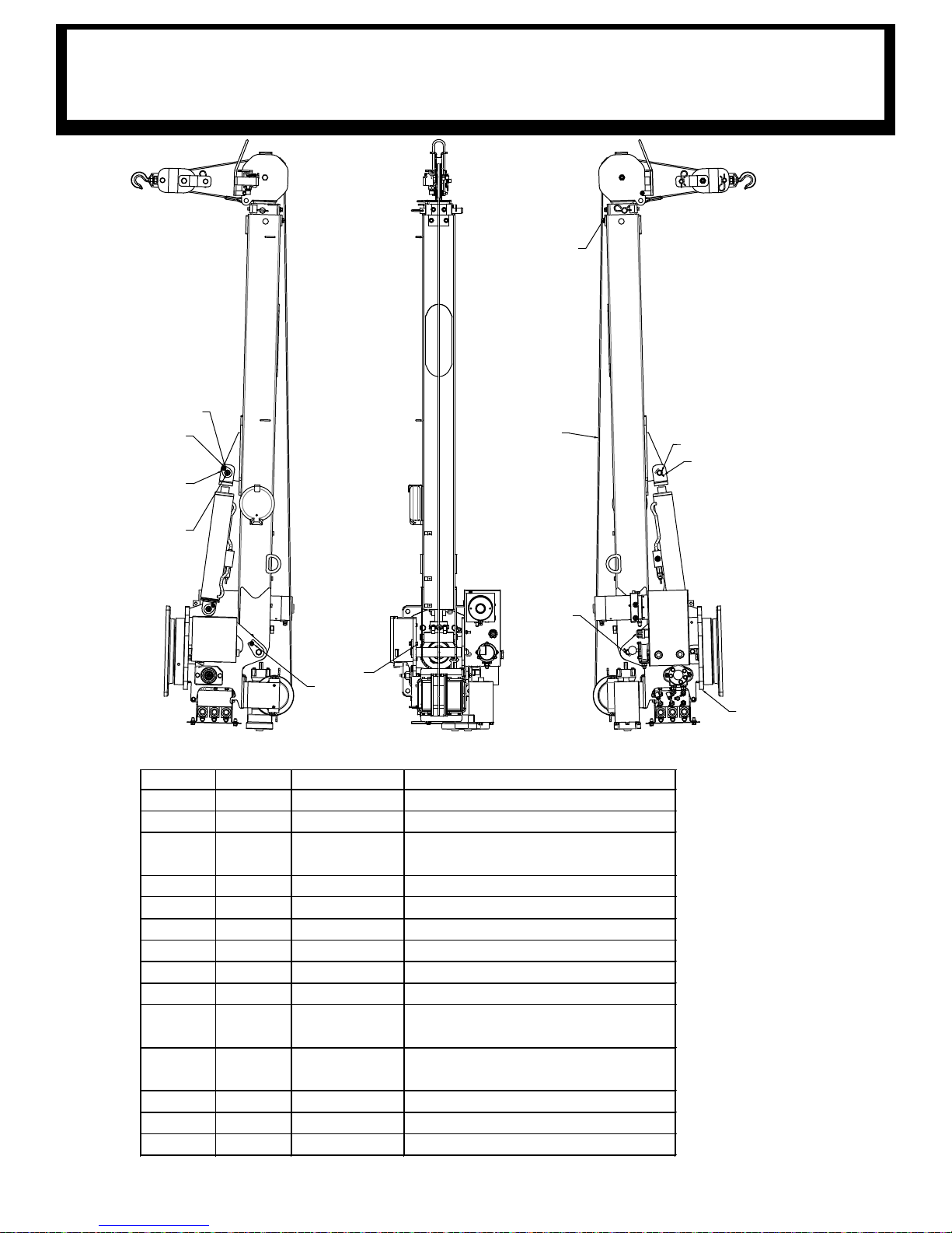
GENERAL ASSEMBLY
ITEM NO. QTY. PART NO. DESCRIPTION
1 1 320988203 PEDEST A L ASSEMBLY, 3203 PRX
2 1 320988102 BOOM ASSY 3203 PRX
3 1 320338002
CABLE ASS'Y , 7/32" x 62FT, THI MBLE
END
4 1 404220000 PIN WDMT BOOM/PED
5 1 320824000 PIN, LIFT CY LINDER
6 2 360678000 PIN, 3/16 COTT ERLESS RING
7* 1 320988004 DECAL LAY OUT, 3203
8* 1 320988012 SHI P KIT, 3203 PR/PRX, HW
9 1 239300000 ZERK, GREA SE
10 1 330371000
SCREW HX HD 3/8-16UNC X 1 LG
GR8
11 1 366159000
SCREW HX HD 3/8-16UNC X 1 1/2 LG
GR8
12 2 02110000
0 WASHER SP LK 3/8
13 2 021200000 WA SHER FL 3/8
14 1 330372000 NUT HX 3/8-16UNC
3203P
R CRANE
*NOT SHOWN FOR CLARITY
33
Page 42
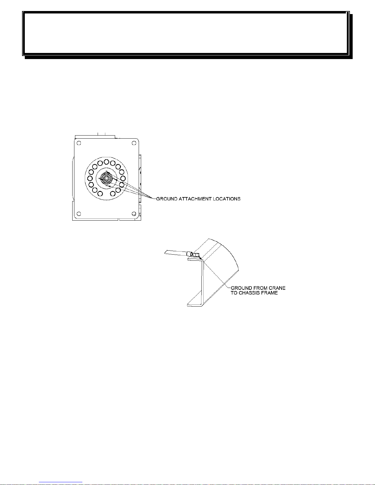
3203PR GENERAL ASSEMBLY
HARD
Attach ground wire (404223020) to bottom of the crane. Run the ground wire
o
wn through the crane box. Locate cable so that it will be protected and avoid
d
sharp edges. Attach ground from crane to chassis frame.
WIRED
34
Page 43
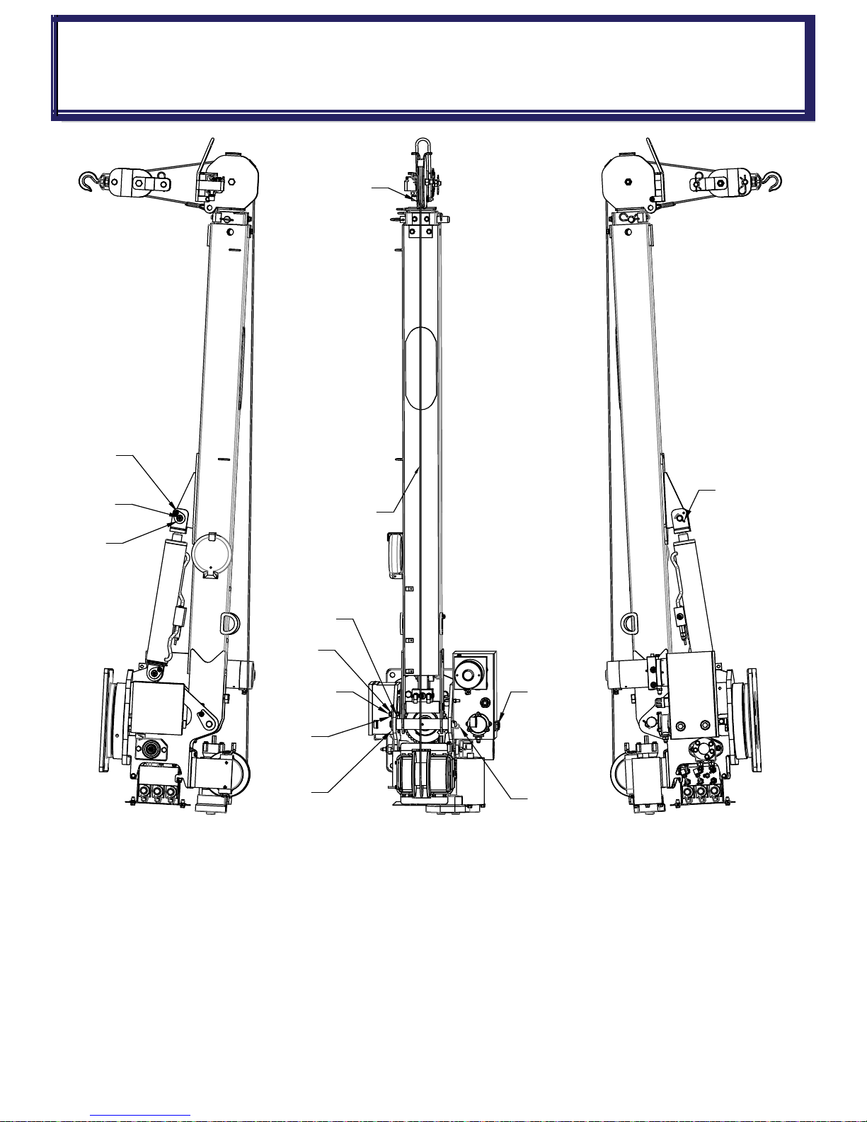
3203PRX GENERAL ASSEMBLY
6
1
3
4
14
12
11
13
2
10
9
5
6
HAR
DWIRED - P/N:320989002
35
Page 44

ITEM
NO.
QTY
PART
NUMBER
DESCRIPTION
1 1 320988203 PEDESTAL ASSEMBLY, 3203 PRX
2 1 320988102 BOOM ASSY 3203 PRX
3 1 320338002 CABLE ASS'Y, 7/32" x 62FT, THIMBLE END
4 1 404220000 PIN WDMT BOOM/PED
5 1 320824000 PIN, LIFT CYLINDER
6 2 360678000 PIN, 3/16 COTTERLESS RING
7* 1 320988004 DECAL LAYOUT, 3203
8* 1 320988012 SHIP KIT, 3203 PR/PRX, HW
9 1 239300000 ZERK, GREASE
10 1 330371000 SCREW HX HD 3/8-16UNC X 1 LG GR8
11 1 366159000
SCREW HX HD 3/8-16UNC X 1 1/2 LG GR8
12 2 021100000 WASHER SP LK 3/8
13 2 021200000 WASHER FL 3/8
14 1 330372000 NUT HX 3/8-16UNC
* NOT SHOWN FOR CLARITY
3203PRX GENERAL ASSEMBLY
HAR
DWIRED-P/N:320989002
36
Page 45
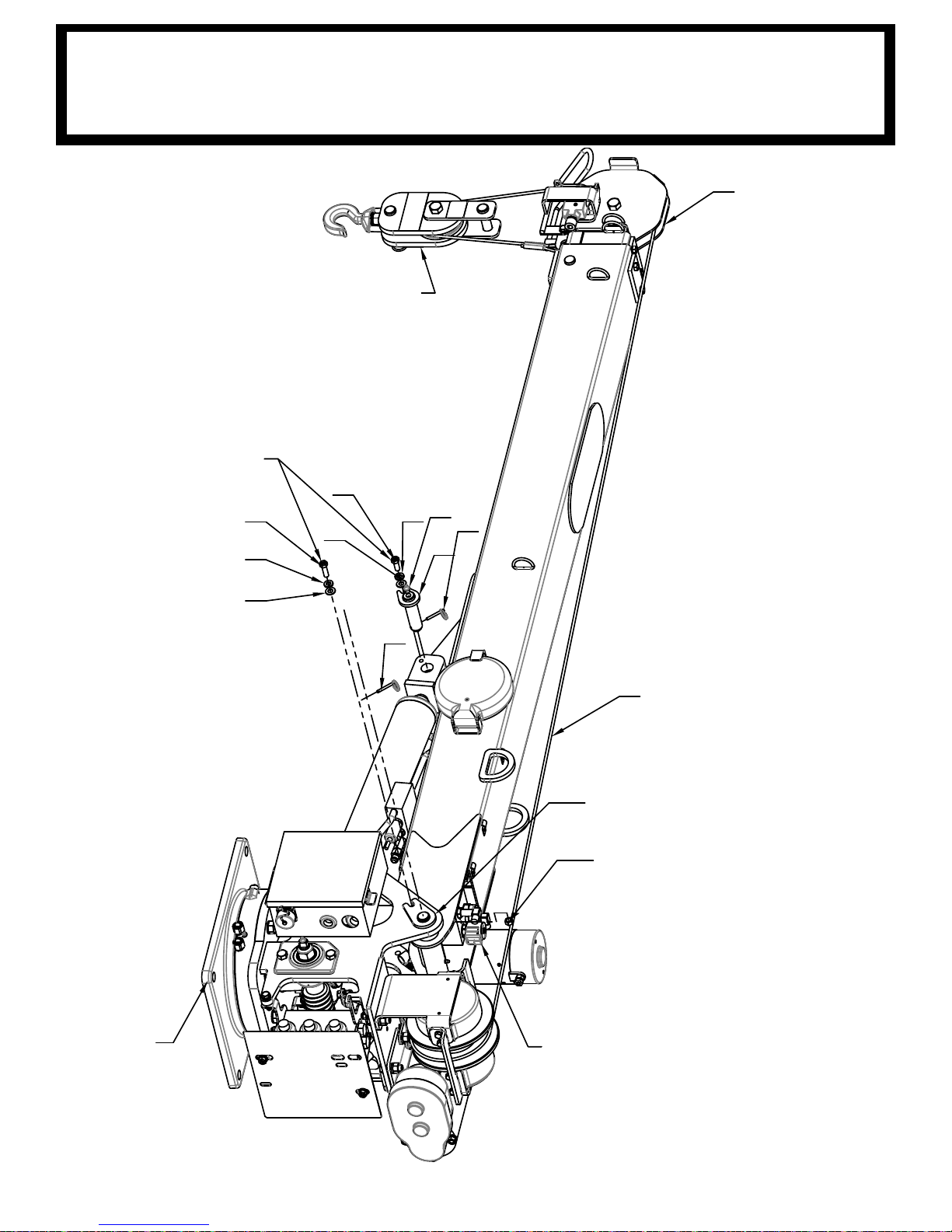
9
4
5
6
7
8
6
7
PLUG REG FROM
320990310 INTO COIL
14
2
TRAVELING BLOCK IS
SHOWN FOR REFERENCE
AND IS LOCATED IN THE
SHIP KIT
APPLY LOCK-TITE
242 OR 243 TO
BOLT THREAD
10
10
13
1
3
3203PRFX GENERAL ASSEMBLY
HAR
DWIRED - P/N: 320990001
37
Page 46

ITEM NO. QTY PART NO. DESCRIPTION
1 1 320990200 PEDESTAL ASSEMBLY, 3203 PRFX
2 1 320990100 BOOM ASSY 3203PRFX
3 1 404220000 PIN WDMT BOOM/PED
4 1 320824000 PIN, LIFT CYLINDER
5 1 239300000 ZERK, GREASE
6 2 021200000 WASHER FL 3/8
7 2 021100000 WASHER SP LK 3/8
8 1 330371000 SCREW HX HD 3/8-16UNC X 1 LG GR8
9 1 330372000 NUT HX 3/8-16UNC
10 2 360678000 PIN, 3/16 COTTERLESS RING
11* 1 320988012 SHIP KIT, 3203 PR/PRX, HW
12* 1 320988004 DECAL LAYOUT, 3203
13 1 366159000 SCREW HX HD 3/8-16UNC X 1 1/2 LG GR8
14 1 320338002 CABLE ASS'Y, 7/32" x 62FT, THIMBLE END
* ITEM NOT SHOWN
3203PRFX GENERAL ASSEMBLY
HAR
DWIRED - P/N: 320990001
38
Page 47
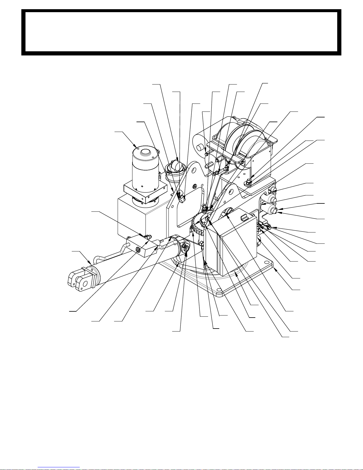
3203PR PEDESTAL ASSEMBLY
ATTACH GROUND CABLE
29
28
37
18
46
2
26
40
53
14
52
38
22
15
16
36
59
7
61
43
30
60
66
17
19
31
11
39
41
4
6
3
ATTACH GROUND
CABLES FROM:
HOIST (600317)
PUMP (600318)
RELAY PANEL (BLACK WIRE)
5
13
12
64
45
251
27
47
48
44
58
37
P/N
: 320988204
HYDRAULICS:
PORT
PORT A-2 CCW BOTTOM MOTOR PORT
PORT B-1 BOOM DOWN
PORT B-2 CW TOP MOTOR PORT
CYLINDER SEAL KIT: 320845002
C’BAL CARTRIDGE: 480188000
A-1 BOOM UP
39
Page 48
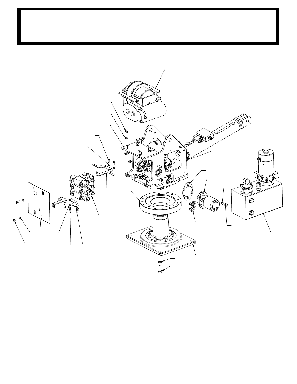
2
16
15
9
8
48
15
16
37
30
18 62
60
20
21
61
59
20
21
1
1
13
12
4
5
3203PR PEDESTAL ASSEMBLY
P/N
: 320988204
40
Page 49
ITEM NO. QTY PART NO. DESCRIPTION
1 1 320988210 PEDESTAL WELDMENT, 3203 PR / PRX / H
2 1 110703 WINCH-DCG8R FOR AUTOCRANE #3203 PRX
3 1 320991240 KIT, HOSE NEXSTAR 3203PRX/4004EH
4 1 320991237 BASE PLATE MACH 3203 LESS GROUND HOLE
5 1 320878000 ROTATION BEARING
6 1 340602000 KEY, 3/4 SQ X 1
7 1 320988253 GEAR, WORM, 4.00 ID, .75 KEY, 3203
8 1 404241285 MOTOR, HYD 8.0 CU IN, SAE 2-BOLT 1" SHAFT
9 1 320879000 SPACER ROTATION
10 1 330483000 SPACER
11 1 404015 WORM SHAFT
12 22 023902000 WASHER FL 5/8 HARDENED
13 22 012198000 SCREW HX HD 5/8-11UNC X 1 3/4 LG GR8
14 6 011603000 SCREW HX HD 1/2-13UNC X 1 3/4 LG
15 10 021500000 WASHER, SP LK 1/2
16 10 017701000 NUT HX 1/2-13UNC
17 2 009109000 SCREW HX HD 3/8-16UNC X 1 1/2 LG
18 7 021100000 WASHER SP LK 3/8
19 4 736274000 NUTSERT 3/8-16UNC X .027-.15 GRIP
20 4 330252000 SCREW HX HD 5/16-18UNC X 3/4 LG GR5
21 4 020601000 WASHER SP LK 5/16
22 3 010201000 SCREW HX HD 1/2-13UNC x 1 1/2 LG
23 4 006200000 SCREW HX HD 1/4-20UNC X 1 1/4 LG
24 4 020200000 WASHER SP LK 1/4
25 2 239300000 ZERK, GREASE
26 2 330372000 NUT HX 3/8-16UNC
27 1 360678000 PIN, 3/16 COTTERLESS RING
28 2 021200000 WASHER FL 3/8
29 1 330394000 SCREW HX HD 3/8-16UNC X 1 1/2 LG
30 3 330371000 SCREW HX HD 3/8-16UNC X 1 LG GR8
31 1 019000000 NUT HX NYLK 7/8-14UNF
32* 2 812026016 HOSE ASSY -4 HOSE -6 FEMALE JIC
33* 1 812209023 HOSE ASSY, SHORT, 23"
3203PR PEDESTAL ASSEMBLY
P/N
320988204
41
Page 50
ITEM NO. QTY PART NO. DESCRIPTION
34* 1 812209028 HOSE ASSY, SHORT, 28"
35 1 202756000 ADAPTER, STRAIGHT 8SAE(M)-6JIC(M)
36 1 320988258 UPPER TWECO BRACKET WLDMT, 3203
37 1 320991279 POWER UNIT, ENTRY LEVEL 3203/4004 EH
38 1 404187000 SPRING PLATE, GROUND BRUSH, 4004
39* 1 320988300 RELAY PANEL ASSEMBLY, 3203
40 1 404198000 SCREW HX HD 3/8-16UNC X 1 1/2 LG, BRONZE
41 1 404213000 SEAL, 2.50 OD X 1.5 ID
42 1 320858000 BEARING, SPHERICAL 1.00 ID
43 1 404028000 RETAINING RING, SNAP RING
44 1 320845000 CYLINDER, LIFT
45 1 320824000 PIN, LIFT CYLINDER
46 2 480024000 MOUNT PENDANT CABLE RETAINER
47 1 320917000 PRESSURE SWITCH, N.C. 1,900 PSI
48* 1 200876000 FITTING 6 SAE/6 JIC STRAIGHT
49* 3 490198000 FITTING 10SAE(M)/6JIC ELBOW 90
50 1 320988270 KIT, HYDRAULIC, 3203 PR
51 1 680156100 KIT-ELECTRICAL, 3203 PR/PRX
52 2 002901000 TERMINAL, RING #4 - 3/8
53 1 002702000 TERMINAL, RING #4 - 5/16
54* 1 660116000 CABLE ASSY, 6 AWG, 16 1/4 " WIRE LGTH
55* 1 600318000 CABLE ASSY, 6 AWG, 11" WIRE LGTH
56 1 002900000 SCREW SET 0.25-20 X 0.25
57* 1 645000000 TWECO, MALE MODIFIED
58 1 320988261 VALVE, FLOW REGULATOR, IN-LINE
59 1 320989204 UPPER VALVE BRACKET, 3203H
60 1 320989203 LOWER VALVE BRACKET, 3203H
61 1 320989420 VALVE ASSY, 3 SPOOL, NON-PROP., 12 VOLT
62 1 366688000 COVER, REAR
63* 2 360447000 FITTING, CAP, JIC, -6
64 1 320989235 BRACKET, POWER UNIT
65* 2 480194000 FITTING 6JIC/6JIC ELBOW 90
66 1 330478000 BEARING HOUSING ASSY
* ITEMS NOT SHOWN
3203PR PEDESTAL ASSEMBLY
P/N
320988204
42
Page 51
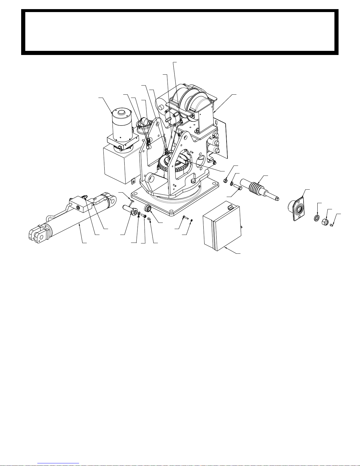
3
68
9
30
24
31
22
23
15
14
13
10
36
24
29
17
39
26
38
59
41
64
33
40
27
28
25
34
32
ATTACH GROUND
CABLES FROM:
HOIST (600317)
PUMP (600318)
RELAY PANEL (BLACK WIRE)
Attach Ground Cable
32
03PRX PEDESTAL ASSEMBLY
P/N: 320988203
HYDR
PORT A-1 RETRACT
PORT A-2 BOOM DOWN
PORT A-3 CCW BOTTOM MOTOR PORT
PORT B-1 EXTEND
PORT B-2 BOOM UP
PORT B-3 CW TOP MOTOR PORT
CYLINDER SEAL KIT: 320845002
C’BAL CARTRIDGE: 480188000
AULICS:
43
Page 52
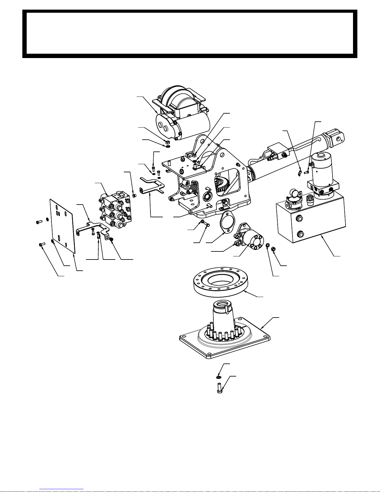
3
15
14
33
14
15
19
64
17
16
8
51
7
14
15
4
2
11
12
29
17
63
19 20 18
61
62
13
18
60
19
20
ATTACH
GROUND
CABLE
3203
PRX PEDESTAL ASSEMBLY
P/N: 320988203
44
Page 53

3203PRX PEDESTAL ASSEMBLY
ITEM NO QTY PART NO. DESCRIPTION
1 1 320988210 PEDESTAL WELDMENT, 3203 PR / PRX / H
2 1 320991237 BASE PLATE MACH 3203 LESS GROUND HOLE
3 1 110703 WINCH-DCG8R FOR AUTOCRANE #3203 PRX
4 1 320878000 ROTATION BEARING
5 1 340602000 KEY, 3/4 SQ X 1
6 1 320988253 GEAR, WORM, 4.00 ID, .75 KEY, 3203
7 1 404241285 MOTOR, HYD 8.0 CU IN, SAE 2-BOLT 1" SHAFT
8 1 320879000 SPACER ROTATION
9 1 330483000 SPACER
10 1 404015000 WORM SHAFT
11 24 023902000 WASHER FL 5/8 HARDENED
12 24 012198000 SCREW HX HD 5/8-11UNC X 1 3/4 LG GR8
13 6 011603000 SCREW HX HD 1/2-13UNC X 1 3/4 LG B
14 10 021500000 WASHER, SP LK 1/2
15 9 017701000 NUT HX 1/2-13UNC
16 2 009109000 SCREW HX HD 3/8-16UNC X 1 1/2 LG
17 5 021100000 WASHER SP LK 3/8
18 4 736274000 NUTSERT 3/8-16UNC X .027-.15 GRIP
19 5 330252000 SCREW HX HD 5/16-18UNC X 3/4 LG GR5
20 4 020601000 WASHER SP LK 5/16
21 3 010201000 SCREW HX HD 1/2-13UNC x 1 1/2 LG
22 4 006200000 SCREW HX
HD 1/4-20UNC X 1 1/4 LG
23 4 0202000000 WASHER SP LK 1/4
24 2 239300000 ZERK, GREASE
25 2 330372000 NUT HX 3/8-16UNC
26 1 360678000 PIN, 3/16 COTTERLESS RING
27 1 320976000 WASHER, FLAT, 3/8 SAE HARDENED
28 1 09116000 SCREW HX HD 3/8-16UNC X 2 GR5
29 3 330371000 SCREW HX HD 3/8-16UNC X 1 LG GR8
30 1 019000000 NUT HX NYLK 7/8-14UNF
31 1 320988300 RELAY PANEL ASSEMBLY, 3203
32 1 320988258 UPPER TWECO BRACKET WLDMT, 3203
33 1 404187000 SPRIN
G PLATE, GROUND BRUSH, 4004
34 1 404198000 SCREW HX HD 3/8-16UNC X 1 1/2 LG, BRONZE
P/N
320988203
45
Page 54
3203PRX PEDESTAL ASSEMBLY
ITEM NO QTY PART NO. DESCRIPTION
35 1 404213000 SEAL, 2.50 OD X 1.5 ID
36 1 320858000 BEARING, SPHERICAL 1.00 ID
37 1 404028000 RETAINING RING, SNAP RING
38 1 320845000 CYLINDER, LIFT
39 1 320824000 PIN, LIFT CYLINDER
40 2 480024000 MOUNT PENDANT CABLE RETAINER
41 1 320917000 PRESSURE SWITCH, N.C. 1,900 PSI
42 16 374085000 NYLON HOSE SLEEVE
43 1 812209028 HOSE ASSY, -6 HOSE, -6 JICF / -6 JICF 90DEG
44 1 812209023 HOSE ASSY, -6 HOSE, -6 JICF / -6 JICF 90DEG
45 2 81203701
8 HOSE ASSEMBLY, -6 JIC 90/-4 HOSE
46 1 812037031 HOSE ASSY, -6 JICF/ -6 90 DEG ELL, -4 HOSE x
47 1 812037027 HOSE ASSY, -6 JICF/ -6 90 DEG ELL, -4 HOSE x
48 2 812026016 HOSE ASSY -4 HOSE -6 FEMALE JIC
49 1 202756000 ADAPTER, STRAIGHT 8SAE(M)-6JIC(M)
50 2 200876000 FITTING 6 SAE/6 JIC STRAIGHT
51 2 490198000 FITTING 10SAE(M)/6JIC ELBOW 90
52 1 320988251 KIT, HYDRAULIC, 3203 PRX/ 4004
55 1 660116000 CABLE ASSY, 6 AWG, 16 1/4"
WIRE LGTH, ø3/8
56 1 600318100
CABLE ASSY, 6 AWG, 24" WIRE LGTH, ø3/8 TMNL, ø5
57 1 002900000 SCREW SET 0.25-20 X 0.25
58 1 645000000 TWECO, MALE MODIFIED
59 1 320988261 VALVE, FLOW REGULATOR, IN-LINE
60 1 320989204 UPPER VALVE BRACKET, 3203H
61 1 320989203 LOWER VALVE BRACKET, 3203H
62 1 320989420 VALVE ASSY, 3 SPOOL, NON-PROP., 12 VOLT
63 1 366688000 COVER, REAR
64 1 320991279 POWER UNIT, ENTRY LEVEL 3203/4004 EH B
65 1 320989235 BRACKET, POWER UNIT
66 1 680156100 KIT-ELECTRICAL, 3203 PR/PRX
67 1 017301000 NUT
HX NYLK 3/8-16UNC CP
68 1 330478000 BEARING HOUSING ASSY
P/N
320988203
46
Page 55

3203PRFX PEDESTAL ASSEMBLY
5
2
13
44
57
56
47
12
71
11
62
60
55
56
57
37
59
51
15
61
38
49
60
20
32 17
69
3
18
51
ATTACH GROUND
CABLES FROM:
HOIST (600317)
PUMP (600318)
RELAY PANEL (BLACK WIRE)
P/N
: 320990200
HYDRAULICS:
T A-1 RETRACT
POR
PORT A-2 BOOM DOWN
PORT A-3 CCW BOTTOM MOTOR PORT
PORT B-1 EXTEND
PORT B-2 BOOM UP
PORT B-3 CW TOP MOTOR PORT
CYLINDER SEAL KIT: 320845002
C’BAL CARTRIDGE: 480188000
47
Page 56

57
56
19
10
31
47
48
6
54
46
45
54
46
45
38
49
49
38
55
5338
31
66
68
65
67
23
24
25
26
26
7
69
5
3203PRFX PEDESTAL ASSEMBLY
P/N
: 320990200
48
Page 57
ITEM
NO.
QTY
PART
NUMBER
DESCRIPTION
1 2 320991240 KIT, HOSE NEXSTAR 3203PRX/4004EH
2 1 404187000 SPRING PLATE, GROUND BRUSH, 4004
3 1 320988258 UPPER TWECO BRACKET WLDMT, 3203
4 1 320988210 PEDESTAL WELDMENT, 3203 PR / PRX / H
5 1 110703 WINCH-DCG8R FOR AUTOCRANE #3203 PRX
6 1 320878000 ROTATION BEARING
7 1 320991237 BASE PLATE MACH 3203 LESS GROUND HOLE
8 1 340602 KEY, 3/4 SQ X 1
9 1 320988253 GEAR, WORM, 4.00 ID, .75 KEY, 3203
10 1 320879000 SPACER ROTATION
11 1 330483 SPACER
12 1 404015 WORM SHAFT
13 1 404198000 SCREW HX HD 3/8-16UNC X 1 1/2 LG, BRONZE
14 1 404213000 SEAL, 2.50 OD X 1.5 ID
15 1 320858000 BEARING, SPHERICAL 1.00 ID
16 1 320824000 PIN, LIFT CYLINDER
17 1 320917000 PRESSURE SWITCH, N.C. 1,900 PSI
18 1 320845000 CYLINDER, LIFT
19 1 404241285 MOTOR, HYD 8.0 CU IN, SAE 2-BOLT 1" SHAFT
20 1 320988261 VALVE, FLOW REGULATOR, IN-LINE
21* 1 812209028
HOSE ASSY, -6 HOSE, -6 JICF / -6 JICF 90DEG SHORT,
28" LONG
22* 1 812209023
HOSE ASSY, -6 HOSE, -6 JICF / -6 JICF 90DEG SHORT,
23" LONG
23* 2 812026016 HOSE ASSY -4 HOSE -6 FEMALE JIC
24* 1 812037027 HOSE ASSY, -6 JICF/ -6 90 DEG ELL, -4 HOSE x 27" LG
25* 1 812037031 HOSE ASSY, -6 JICF/ -6 90 DEG ELL, -4 HOSE x 31" LG
26* 2 812037018 HOSE ASSEMBLY, -6 JIC 90/-4 HOSE
27* 16 374085000 NYLON HOSE SLEEVE
28* 1 480194000 FITTING 6JIC/6JIC ELBOW 90
29* 1 202756000 ADAPTER, STRAIGHT 8SAE(M)-6JIC(M)
30 1 320988251 KIT, HYDRAULIC, 3203 PRX/ 4004
31* 2 490198 FITTING 10SAE(M)/6JIC ELBOW 90
32* 2 200876 FITTING 6 SAE/6 JIC STRAIGHT
33 1 680156100 KIT-ELECTRICAL, 3203 PR/PRX
34** 1 660116000
CABLE ASSY, 6 AWG, 16 1/4" WIRE LGTH, ø3/8 TMNL,
ø5/16 TMNL
35** 1 600318100
CABLE ASSY, 6 AWG, 24" WIRE LGTH, ø3/8 TMNL, ø5/16
TMNL
3203PRFX PEDESTAL ASSEMBLY
P/N
: 320990200
49
Page 58

ITEM
NO.
QTY
PART
NUMBER
DESCRIPTION
36** 1 645000000 TWECO, MALE MODIFIED
37** 1 320988300 RELAY PANEL ASSEMBLY, 3203
38 6 021100000 WASHER SP LK 3/8
39 1 017301000 NUT HX NYLK 3/8-16UNC CP
40 2 320976000 WASHER, FLAT, 3/8 SAE HARDENED
41 1 8702000 SCREW HX HD 3/8-16UNC X 1 1/4 LG GR5
42 1 009116000 SCREW HX HD 3/8-16UNC X 2 GR5
43 2 480024000 MOUNT PENDANT CABLE RETAINER
44 3 330372000 NUT HX 3/8-16UNC
45 4 020601000 WASHER SP LK 5/16
46 5 330252000 SCREW HX HD 5/16-18UNC X 3/4 LG GR5
47 23 012198000 SCREW HX HD 5/8-11UNC X 1 3/4 LG GR8
48 23 023902000 WASHER FL 5/8 HARDENED
49 3 330371000 SCREW HX HD 3/8-16UNC X 1 LG GR8
50 1 002900000 SCREW SET 0.25-20 X 0.25
51 4 006200000 SCREW HX HD 1/4-20UNC X 1 1/4 LG
52 1 404028000 RETAINING RING, SNAP RING
53 2 09109000 SCREW HX HD 3/8-16UNC X 1 1/2 LG
54 4 736274000 NUTSERT 3/8-16UNC X .027-.15 GRIP
55 5 011603000 SCREW HX HD 1/2-13UNC X 1 3/4 LG
56 8 021500000 WASHER, SP LK 1/2
57 8 017701000 NUT HX 1/2-13UNC
58 3 010201000 SCREW HX HD 1/2-13UNC x 1 1/2 LG
59 4 020200000 WASHER SP LK 1/4
60 2 023930000 ZERK, GREASE
61 1 360678000 PIN, 3/16 COTTERLESS RING
62 1 019000000 NUT HX NYLK 7/8-14UNF
63 1 320990310 HARNESS, WIRE, REGENERATIVE CIRCUIT, 3203PRFX
64 1 320990201 PRESSURE SWITCH, NC, 1450 PSI, 10 AMP
65 1 320989420 VALVE ASSY, 3 SPOOL, NON-PROP., 12 VOLT
66 1 320989204 UPPER VALVE BRACKET, 3203H
67 1 320989203 LOWER VALVE BRACKET, 3203H
68 1 366688000 COVER, REAR
69 1 320991279 POWER UNIT, ENTRY LEVEL 3203/4004 EH
70 1 320989235 BRACKET, POWER UNIT
71 1 330478000 BEARING HOUSING ASSY
* HYDRAULIC KIT 320988251
** ELECTRICAL KIT 680156100
3203PRFX PEDESTAL ASSEMBLY
P/N
: 320990200
50
Page 59
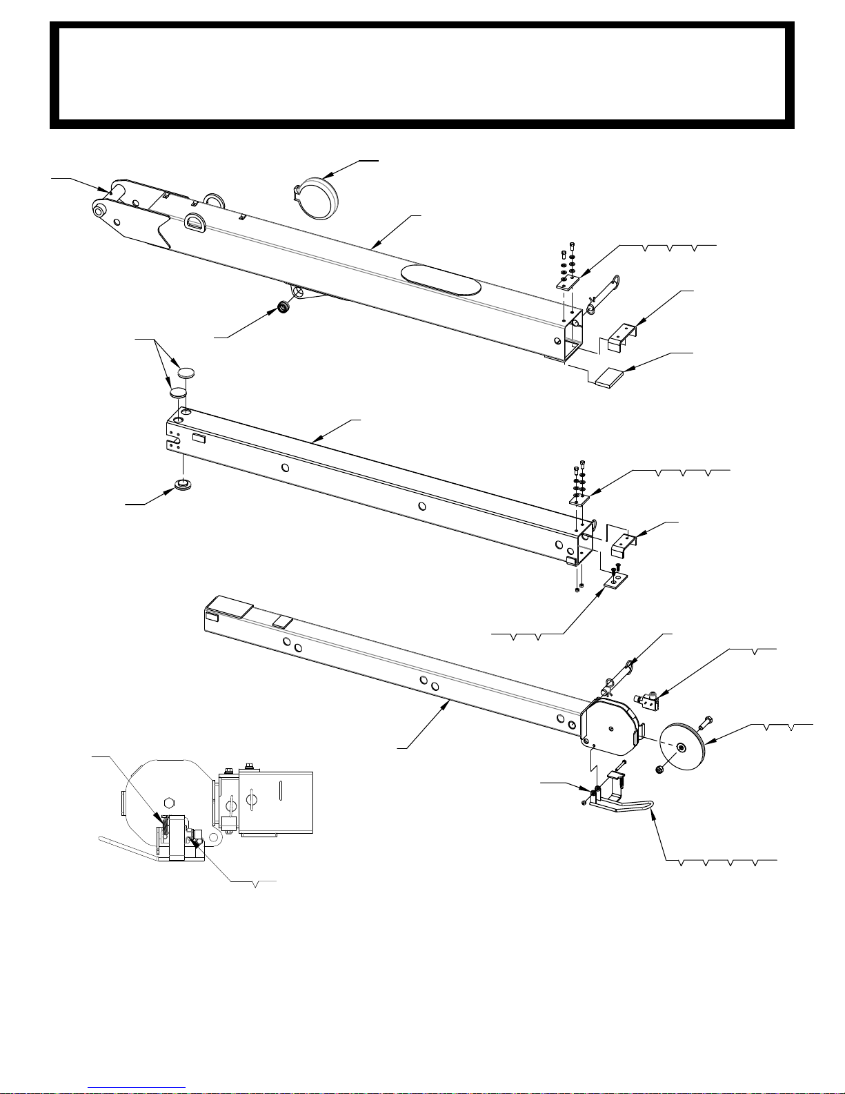
14
27 28 25
15 27 28 25
172021
6
9 22 26 21
7
16
4
18
18
3
11 12
1
2
10
19
8
5 23
24
13
ADD WASHERS BETWEEN
BAIL
AND CROWN ALSO
13
11
12
3203PR BOOM ASSEMBLY
P/N
: 320988103
NOTE:
APPLY LOCTITE 242
8 PLC’S BEFORE INSTALLING
CYLINDER SEAL KIT: 320835002
C’BAL
CARTRIDGE: 480188000
TO BOLT THREADS.
51
Page 60
ITEM
NO.
QTY.
PART
NUMBER
DESCRIPTION
1 1 320988110 LOWER BOOM WELDMENT, 3203 PR/PRX
2 1 320988165 MID BOOM WMT, 3203
3 1 320988160 UPPER BOOM WLDMT 3203
4 1 320858000 BEARING, SPHERICAL 1.00 ID
5 1 320883000 SHEAVE ASSEMBLY
6 1 366112000 STOP UPPER BOOM
7 1 366183000 STOP CENTER BOOM
8 2 366190000 PIN ASSY W/LANYARD
9 1 320871000 BAIL WELDMENT
10 1 404205000 CORD REEL ASSY
11 1 646900000 SWITCH, ANTI-TWO BLOCK
12 1 642918000 CORD CONNECTOR
13 1 366678000 SPRING, EXTENSION
14 1 366201000 WEAR PAD 3 .75 X 2.00 X .313
15 1 366202000 PAD, BOOM TOP
16 1 320988155 BOOM PAD 4.50 X 2.50 X .50, 3203
17 1 320990104 WEAR PAD, 2 X 4 X .25, W/ CSINK HOLES
18 3 407203000 PAD, BOOM, 2.50 O.D. x .563 THK
19 1 239000000 ZERK DRIVE GR
20 2 320990105 SCREW, FLAT HEAD, 5/16-18 UNC X 1, ZP
21 3 016801000 NUT HX NYLK 5/16-18UNC CP
22 1 811029000 SCREW HX HD 5/16-18UNC X 2 1/2 LG
23 1 366393000 SCREW HX HD 5/8-11UNC X 2 1/2 LG GR8
24 1 018200000 NUT HX NY LK 5/8-11UNC
25 4 738733100 SCREW HX HD 3/8-24UNF X 7/8 LG
26 4 020901000 WASHER FL 5/16
27 8 021200000 WASHER FL 3/8
28 4 021100000 WASHER SP LK 3/8
3203PR BOOM ASSEMBLY
P/N
: 320988103
52
Page 61

19
17
18
20 33
34
31
21333431
2326
14
6
1527 32
14
7
22
4
1112
1030
14
24
24
13
9
3
17 18
1
2
16
25
8
5 28 29
19
ADD WASHERS BETWEEN
BAIL AND CROWN ALSO
3203PRX BOOM ASSEMBLY
P/N
: 320988102
NOTE: APPLY LOCTITE 242 TO BOLT
CYLINDER S
C’BAL CARTRIDGE: 480188000
THREADS. 8 PLC’S BEFORE INSTALLING
EAL KIT: 320835002
53
Page 62
ITEM NO. QTY
PART
NUMBER
DESCRIPTION
1 1 320988110 LOWER BOOM WELDMENT, 3203 PR/PRX
2 1 320988165 MID BOOM WMT, 3203
3 1 320988160 UPPER BOOM WLDMT 3203
4 1 320858000 BEARING, SPHERICAL 1.00 ID
5 1 320883000 SHEAVE ASSEMBLY
6 1 366112000 STOP UPPER BOOM
7 1 366183000 STOP CENTER BOOM
8 1 366190000 PIN ASSY W/LANYARD
9 1 320988142 EXTENSION CYLINDER, 3203
10 2 320888001 RETAINER, EXTENSION CYLINDER
11 1 320988115 PIN 1 DIA X 6.905 LG, 3203
12 2 360122000 RING RETAINING 5100-98
13 2 330645000 FITTING 90 6-SAE/6-JIC LONG
14 11 016801000 NUT HX NYLK 5/16-18UNC CP
15 1 320871000 BAIL WELDMENT
16 1 404205000 CORD REEL ASSY
17 1 646900000 SWITCH, ANTI-TWO BLOCK
18 1 642918000 CORD CONNECTOR
19 1 366678000 SPRING, EXTENSION
20 1 366201000 WEAR PAD 3 .75 X 2.00 X .313
21 1 366202000 PAD, BOOM TOP
22 1 320988155 BOOM PAD 4.50 X 2.50 X .50, 3203
23 1 320990104 WEAR PAD, 2 X 4 X .25, W/ CSINK HOLES
24 3 407203000 PAD, BOOM, 2.50 O.D. x .563 THK
25 1 239000000 ZERK DRIVE GR
26 2 320990105 SCREW, FLAT HEAD, 5/16-18 UNC X 1, ZP
27 1 811029 SCREW HX HD 5/16-18UNC X 2 1/2 LG
28 1 366393000 SCREW HX HD 5/8-11UNC X 2 1/2 LG GR8
29 1 018200000 NUT HX NY LK 5/8-11UNC
30 8 007804000 SCREW HX HD 5/16-18UNC X 1 1/4 LG CP
31 4 738733100 SCREW HX HD 3/8-24UNF X 7/8 LG
32 4 020901000 WASHER FL 5/16
33 8 021200000 WASHER FL 3/8
34 4 021100000 WASHER SP LK 3/8
3203PRX BOOM ASSEMBLY
P/N
: 320988102
54
Page 63

11
30
17
18
3
14
16
32
33
26
10
9
21
24
28
12
8
27
25
4
1 19
13
20
23
29
15
7
22
5
2
6
34
19
19
30
17
19
22
22
28
31
25
22
3203PRFX BOOM ASSEMBLY
P/N
: 320990100
CYLINDER SEAL KIT: 320988146
BAL CARTRIDGE: 480188000
C’
55
Page 64

ITEM
NO.
QTY
PART
NUMBER
DESCRIPTION
1 1 320988145
CYLINDER, TELESCOPIC, 48" FIRST STAGE, 48"
SECOND STAGE, 3-3/8 OD
2 1 320990110 LOWER BOOM WMT 3203 PRFX
3 1 320990120 MID BOOM WMT 3203 PRFX
4 1 738732000 PIN 1n X 4.063 LG
5 1 320988115 PIN 1 DIA X 6.905 LG, 3203
6 1 239000000 ZERK DRIVE GR
7 1 320858000 BEARING, SPHERICAL 1.00 ID
8 1 320871000 BAIL WELDMENT
9 1 646900000 SWITCH, ANTI-TWO BLOCK
10 1 642918000 CORD CONNECTOR
11 1 404205000 CORD REEL ASSY
12 1 366678000 SPRING, EXTENSION
13 2 330645000 FITTING 90 6-SAE/6-JIC LONG
14 2 366483000 PLATE, WEAR PAD .25 X 2 X 4
15 1 320988156 BOOM PAD WITH NUTS, 4.75 X 3 X .313, 3203
16 1 320990104 WEAR PAD, 2 X 4 X .25, W/ CSINK HOLES
17 2 366201000 WEAR PAD 3 .75 X 2.00 X .313
18 1 320988155 BOOM PAD 4.75 X 2.50 X .50, 3203
19 8 360767000 PAD BOOM 1.5 O.D.
20 1 407202000 PAD BOOM 2.50 O.D.
21 1 320883000 SHEAVE ASSEMBLY
22 4 360122000 RING RETAINING 5100-98
23 2 460177162 SCREW SOC HD 5/8-11UNC X 3/4 LG
24 1 811029000 SCREW HX HD 5/16-18UNC X 2 1/2 LG
25 3 016801000 NUT HX NYLK 5/16-18UNC CP
26 1 366393000 SCREW HX HD 5/8-11UNC X 2 1/2 LG GR8
27 1 018200000 NUT HX NY LK 5/8-11UNC
28 4 020901000 WASHER FL 5/16
29 4 005406000 SCREW HX HD 1/4-28UNF X 1/2 LG
30 4 738733000 SCREW HX HD 3/8-24UNF X 3/4 LG
31 1 320990101
VALVE, SPOOL, 3-WAY, W/ COIL & DEUTSCH
CONNECTION
32 2 320990105 SCREW, FLAT HEAD, 5/16-18 UNC X 1, ZP
33 1 320990140 UPPER BOOM WMT 3203 PRFX
34 1 470048000 PAD, BOOM 2.50 O.D. X 0.063 THICK
3203PRFX BOOM ASSEMBLY
P/N
: 320990100
56
Page 65
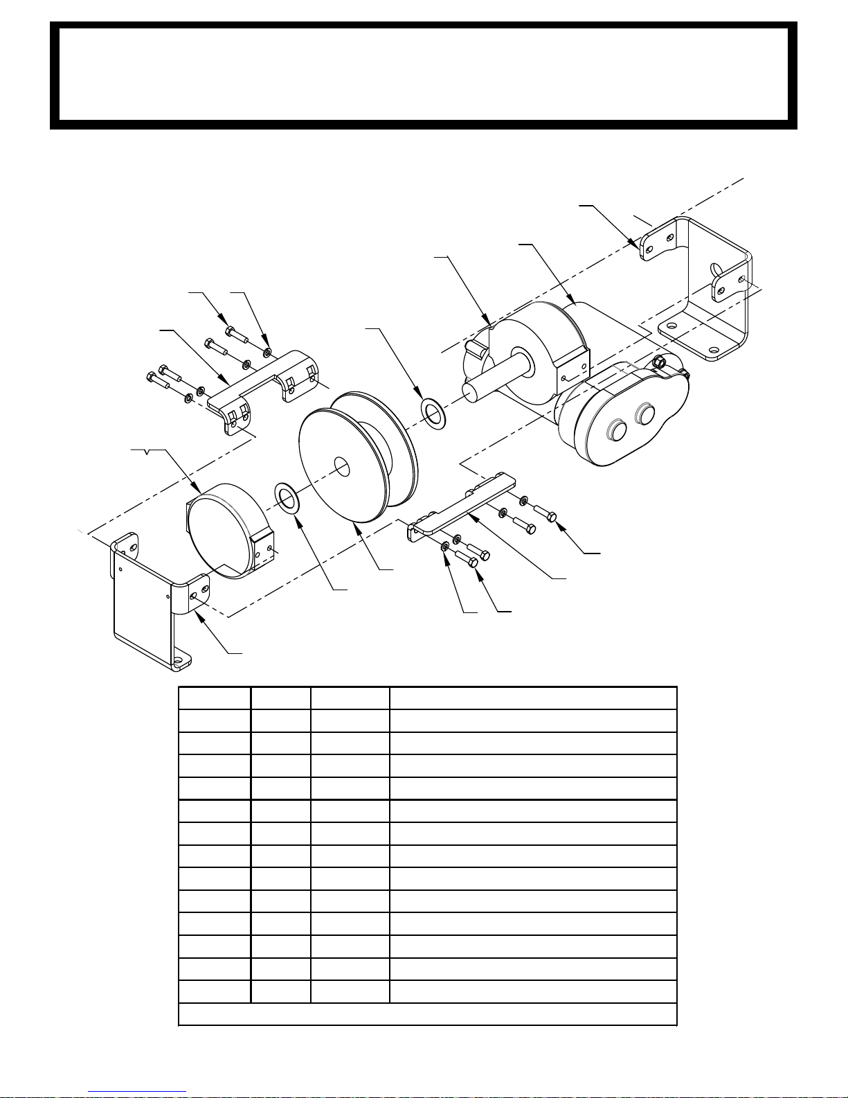
8
7
3
1
5
5
2
4
78
6
910
11
12
13
ITEM NO. QTY PART NO. DESCRIPTION
1 1 320836 WINCH MOUNTING BRACKET CS
2 1 320837 WINCH MOUNTING BRACKET SS
3 1 320838 WINCH TIE BAR
4 1 320839 WINCH TIE BAR, FRONT
5 2 320887 BEARING, BRONZE
6 1 320379 DRUM
7 8 418163 WASHER SP LK 5/16
8 7 414136 SCREW HX HD 5/16-18UNC X 1 1/4 LG CP
9 1 412003 FLANGE BEARING
10 1 338053 WINCH END BEARING
11 1 414865 CAPSCREW-5/16-18NCX1LG HX SOC HD
12 1 296907 HSG ASSY-SPUR GEAR
13* 1 262037 MTR ASS'Y-12V, 2.5 HP
*In
cluded with Item No. 12
3203PR/PRX HOIST ASSEMBLY
P/N
: 110703
57
Page 66
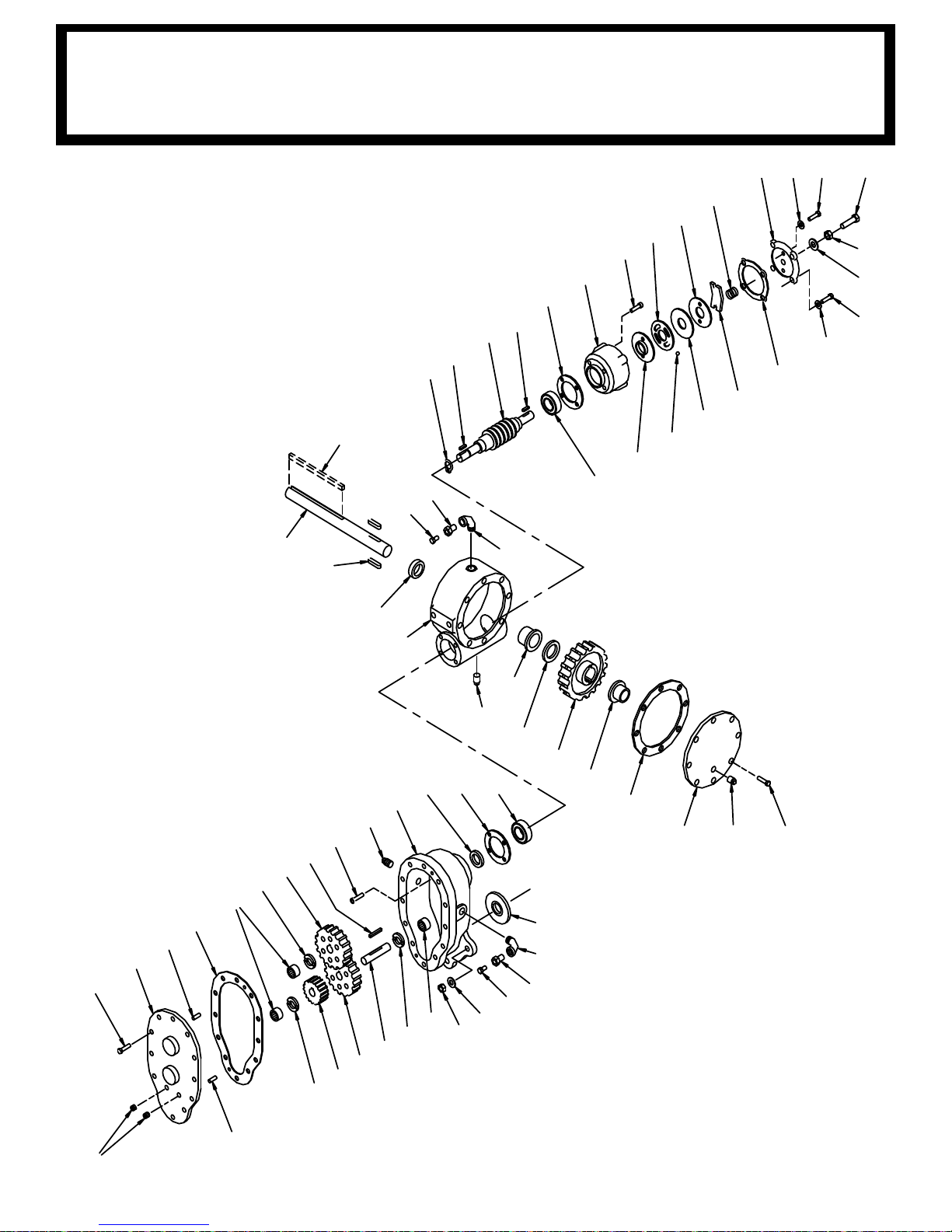
22
42
10
32
2
19
61
5 38 65 31
30
37
59
35
45
1
55
23
13
25
51
27
63
8
26
44
3
51 28
12
11
56
42
25
52
33
16
7
62
24
43
54
4
66
54
62
24
62
20
7
6
50
47
39
36
58
40
29
21
18
57
47
53
17
41
14
60
15
3203PR/PRX HOIST ACTUATOR
58
Page 67

ITEM NO. QT Y. PART NO. DESCRIPTION
1 1 306034 SPRING FLAT
2 1 314008 PLATE CAM
3 1 328009 COVER GEAR HOUSING
4 1 328106 COVER WORM GEAR HOUSING
5 1 328128 COVER BRAKE
6 1 334001 IDLER GEAR
7 2 334003 SPUR GEAR
8 1 334007 GEAR WORM RH
9
10 1 338007 HOUSING BRAKE
11 1 338203 SPUR GEAR HOUSING
12 1 338238 GEAR HOUSING
13 1 340002 HUB BRAKE
14 1 342023 KEY 3/16 SQ X 1/2 LG
15 1 342027 KEY 3/16 SQ X 1 LG
16 1 342033 KEY 3/16 SQ X 1 7/16 LG
17 1 342198 KEY 1/4 SQ X 2 1/8 LG
18 2 342075 KEY RD 5/16 X 5/16 X 15/16 LG
19 1 352022 PLATE RETAINER
20 1 356901 SPUR GEAR SHAFT
21 1 357515 OUTPUT SHAFT
22 1 368192 WORM R.H.
23 2 400003 BALL
24 3 402001 BEARING NEEDLE
25 2 402002 BEARING BALL
26 1 412003 BUSHING
27 1 412046 BUSHING
28 8 414020 SCREW HX HD 1/4-20UNC X 3/4 LG NY LK
29 12 414038 SCREW HX HD 1/4-20UNC X 3/4 LG
30 4 414039 SCREW HX HD 1/4-20UNC X 1 LG
31 1 414224 SCREW HX HD 3/8-16UNC X 1 1/2 LG ALL THD
32 4 414821 SCREW BTN HD 1/4-20UNC X 7/8 LG
33 4 414845 SCREW SOC HD 1/4-20UNC X 1 LG
34
35 1 418036 NUT JAM 3/8-16UNC
36 3 418040 NUT HX 3/8-24UNF
37 4 486070 WASHER SP LK 1/4 MED SECT
38 2 418154 WASHER FL 1/4 ALUM
39 3 418177 WASHER SP LK 3/8
40 1 432011 ELL 90 DEG 3/8-18 NPT BOTH ENDS
41 1 432012 ELL 90 DEG 1/4-18 NPT BOTH ENDS
42 2 442184 GASKET BEARING
43 1 442185 GASKET SPUR GEAR HOUSING
44 1 442186 GASKET GEAR HOUSING COVER
NOT USED
NOT USED
3203PR/PRX HOIST ACTUATOR
59
Page 68
ITEM NO.
QTY. PART NO. DESCRIPTION
44 1 442186 GASKET GEAR HOUSING COVER
45 1 442189 GASKET BRAKE COVER
46
47 2 456008 FITTING RELIEF
48
49
50 1 468002 REDUCER -6NPT/-2NPT
51 2 468010 PLUG PIPE -4NPT SQ HD
52 1 468018 PLUG PIPE -6NPT HX SOC HEADLESS
53 1 468024 REDUCER -4NPT/-2NPT
54 2 470001 PIN DOWELL
55 1 474001 PLATE THRUST
56 1 486009 OIL SEAL 3/4 ID X 1 1/4 OD X 1/4 THK
57 1 486017 OIL SEAL 1 1/4 ID X 1 3/4 OD X 1/4 THK
58 1 486023 OIL SEAL 1 1/2 ID X 2 1/4 OD X 5/16 THK
59
60 1 490003 SNAP RING
61 1 494007 SPRING
62 3
518002 WASHER THRUST
63 1 518015 WASHER THRUST
64 1 518018 WASHER FIBER
65 1 414021 SCREW HX HD 1/4-20UNC X 1 LG NYLK
66 2 468017 PIPE PLUG SOC HD -4NPT
NOT USED
NOT USED
NOT USED
NOT USED
3203PR/PRX HOIST ACTUATOR
60
Page 69

ITEM
NO. QTY
PART
NUMBER
DESCRIPTION
1 1 100309000 SWIVEL HOOK ASSY W/LATCH
2 2 320403000 SIDE PLATE, 3203
3 1 200909000 SHEAVE ASSEMBLY
4 2 320404000 BLOCK TRAVELING
5 2 320434001 PIN, 3/4 X 2-3/4LG
6 1 018200000 NUT HX NY LK 5/8-11UNC
7 1 013512000 SCREW HX HD 5/8-11UNC X 3 1/2 LG
8 2 366813000 PIN HITCH
9 2 330100000 WASHER, FL 5/8 X 7/8 OD
10 2 320433100 DECAL, TRAVELING BLOCK 3203
11 2 040518000 DECAL STAY CLEAR OF LOAD
5
7
4
2
3
9
9
2
4
11
1
8
6
8
5
10
32
03 TRAVELING BLOCK ASSEMBLY
P/N: 320433000
61
Page 70

NOTE
S
62
Page 71
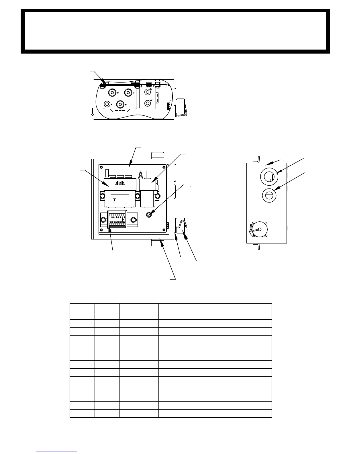
4
3
6
REF FOR REPLACEMENT PART ONLY
(680178000) RECEPTACLE W/WIRE PIGTAIL
2
A
1
7 5
12
5
9
8
13
ITEM NO. QTY PART NO. DESCRIPTION
1 1 320988256 BULKHEAD ELECTRICAL PLATE
2 1 320589000 RELAY, HOIST
3 1 320584000 RELAY, POWER UNIT
4 1 320988399 TERMINAL STRIP 8
5 10 736272000 NUTSERT 1/4-20UNC X .027-.165 GRIP
6 1 320562000 RECEPTACLE, 11 PIN, 1/4 TURN, BAYONET
7 6 360493000 SCREW HX WHIZ-LK 1/4-20UNC X 1/2 LG
8 1 371024000 GROMET 3/4" I.D.
9 1 320988255 ELECTRICAL BOX, 8X8X4
10 7 366367000 DEUTSCH 2 PIN Assembly
11 1 360769001 HOUSING, DEUTSCH 2-PIN RECEPTACLE
12 1 320564000 CAP WITH CHAIN (FOR RECEPTACLE)
13 1 750282000 GROMMET, RUBBER, 1.375 OD, 1.00 ID
3203PR/PRX RELAY PANEL ASSEMBLY
P/N
: 320988300
63
Page 72
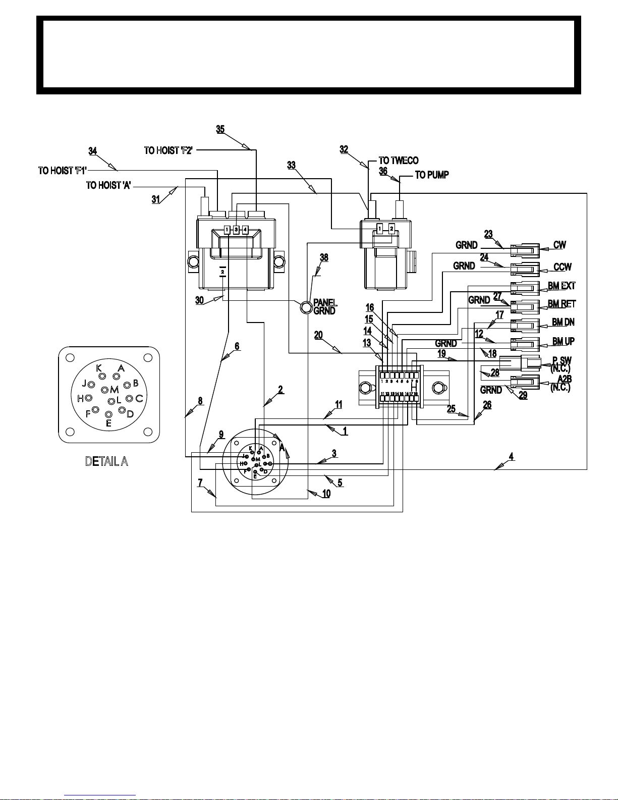
3203PR/PRX ELECTRICAL SCHEMATIC
DETAIL A
P/N
: 320988300
64
Page 73
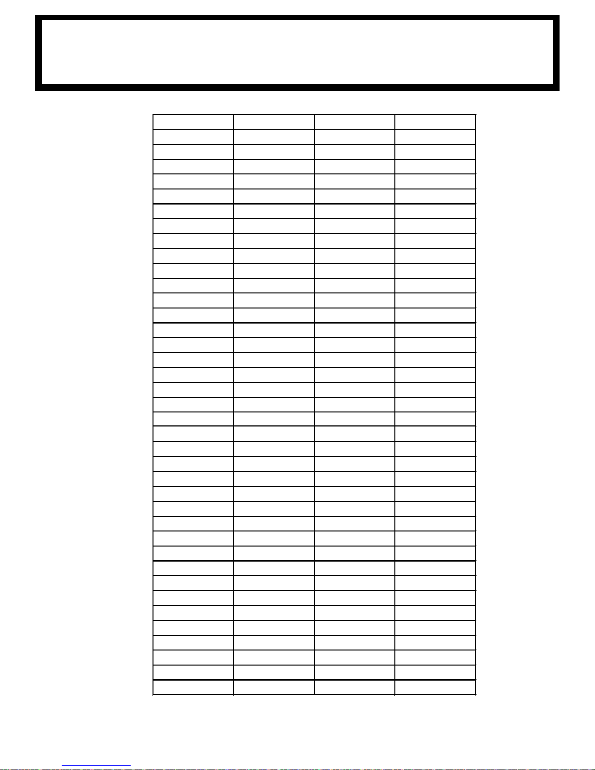
ITEM NO. PART NO. COLOR GAGE
1 REF YELLOW 16
2 REF GREEN 16
3 REF ORANGE 16
4 REF RED 16
5 REF WHITE/RED 16
6 REF RED/BLACK 16
7 REF GREEN/BLACK 16
8 REF WHITE/BLACK 16
9 REF BLUE 16
10 REF BLACK 16
11 REF ORANGE/BLACK 16
12 REF WHITE 16
13 REF
ORANGE
16
14 REF WHITE/RED 16
15 REF GREEN/BLACK 16
16 REF ORANGE/BLACK 16
17 REF BLUE 16
18 REF YELLOW 16
19 REF RED 16
20 REF GREEN/WHITE 16
21
22
23 REF WHITE 16
24 REF WHITE 16
25 REF RED/WHITE 16
26 REF BLUE/WHITE 16
27 REF WHITE 16
28 REF WHITE/RED 16
29 REF WH
ITE 16
30 REF WHITE 16
31 320988331 BLACK 6
32 320988332 BLACK 6
33 320988333 BLACK 6
34 320988334 BLACK 6
35 320988335 BLACK 6
36 320988336 BLACK 6
37 REF WHITE 16
38 320988338 BLACK 16
NOT USED
NOT USED
3203PR/PRX ELECTRICAL SCHEMATIC
P/N
: 320988300
65
Page 74
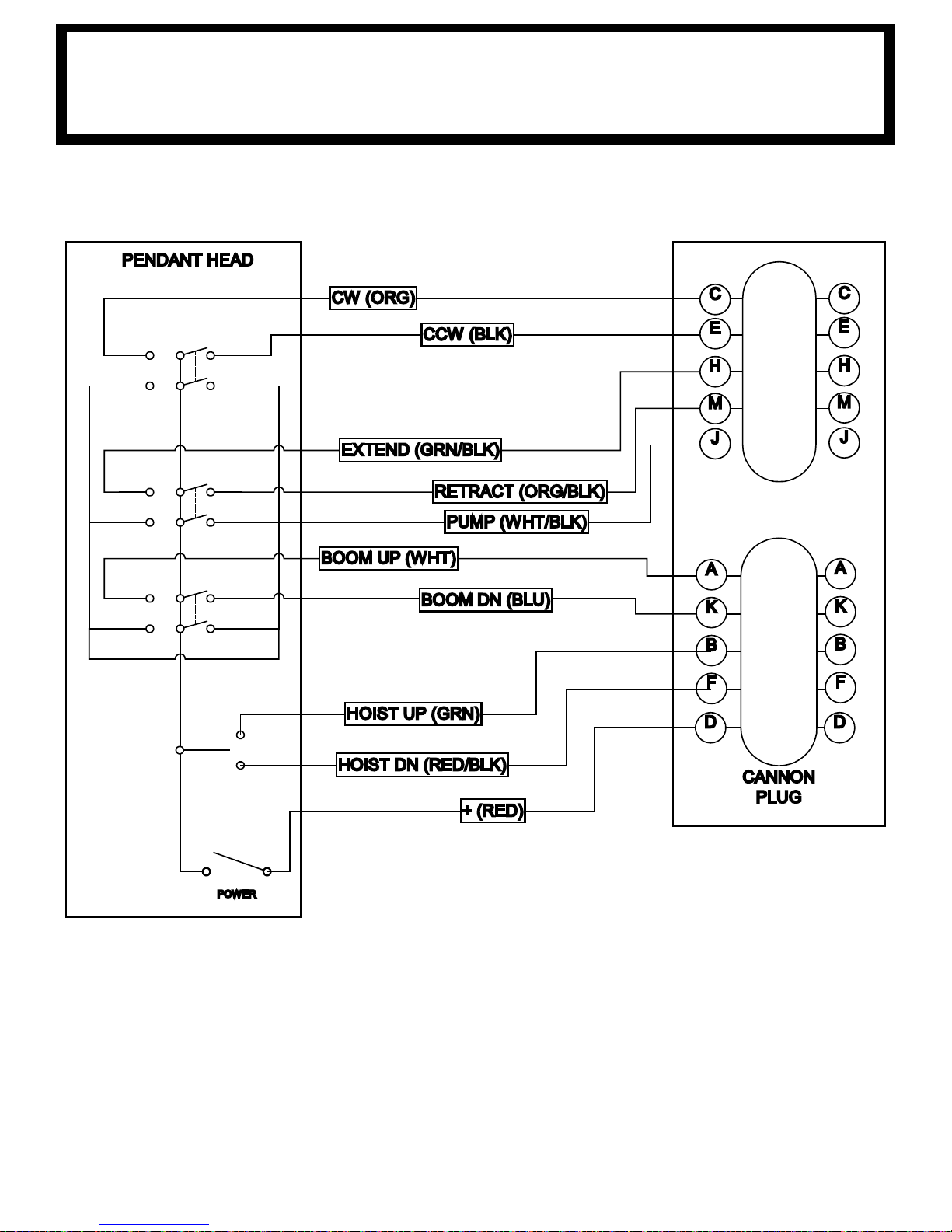
RETRACT (ORG/BLK)
CCW (BLK)
CANNON
PLUG
CW (ORG)
EXTEND (GRN/BLK)
BOOM UP (WHT)
BOOM DN (BLU)
PUMP (WHT/BLK)
C
E
H
M
J
A
K
B
F
C
E
H
M
J
A
K
B
F
PENDANT HEAD
POWER
D D
+ (RED)
HOIST UP (GRN)
HOIST DN (RED/BLK)
3203PR/PRX PENDANT ASSEMBLY
P/N
: 680179000
66
Page 75

6
9
3
7
10
4
2
1
11
6
5
8
ITEM
NO.
QTY.
PART
NO. DESCRIPTION
1 1 480501000 PENDANT HOUSING
2 1 366719000 DECAL, PENDANT 8 FUNC W/PWR
3 1 480504000 PENDANT BACK PLATE
4 1 600820000 CORD GRIP, 3/4 NPT, .50-.625" CORD
5 1 680179001 PENDANT CABLE, 11 PIN BAYONET
6 1 480598000 COVER TRIGGER OPENING
7 1 750090000 TOGGLE SWITCH, 1 POLE, 2 POSITION
8 4 634200000 TOGGLE SWITCH KIT
9 4 001004000 SCREW PN HD #6 X 3/4 LG
10 2 002607000 SCREW RD HD #10-24UNC X 3/4 LG CP
11 2 015801000 NUT HX NYLK #10-24UNC ZP
32
03PR/PRX PENDANT ASSEMBLY
P/N: 680179000
67
Page 76

NOTE
S
68
Page 77
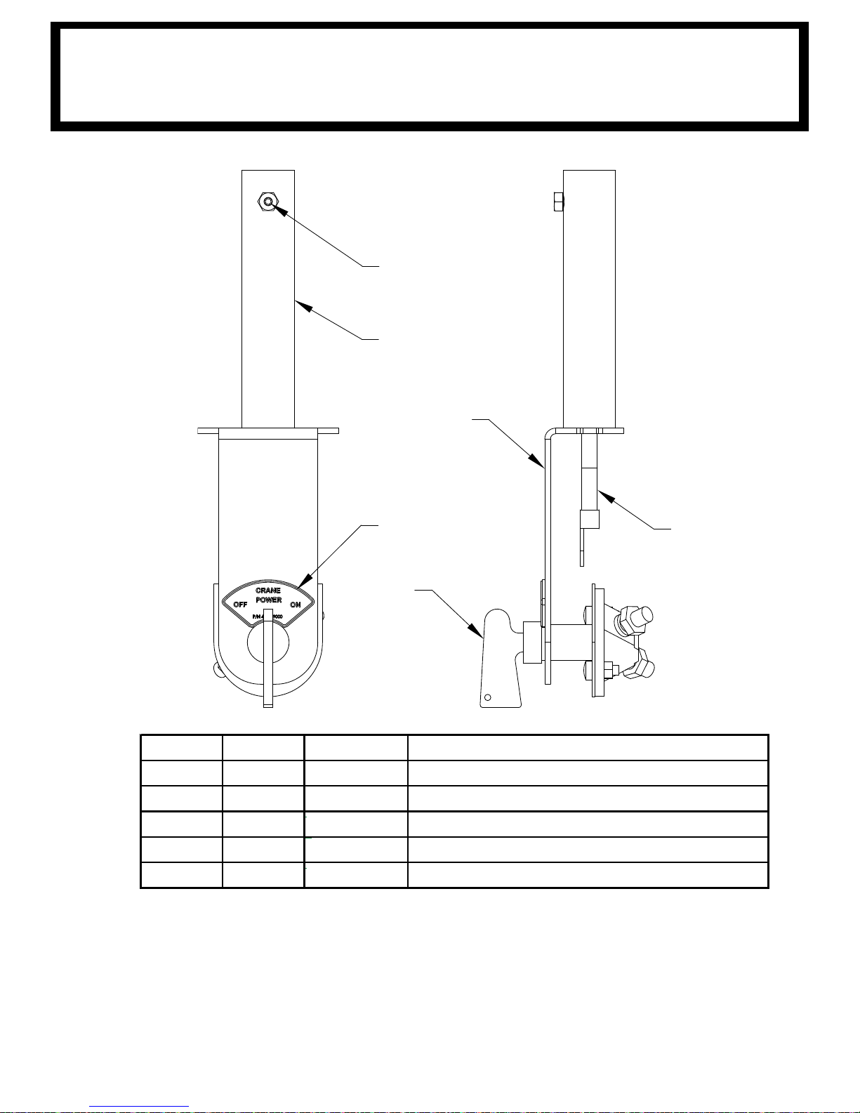
ITEM NO. QTY PART NO. DESCRIPTION
1 1 404217000 LOWER TWECO WELD WITH SWITCH MOUNT
2 1 404224000 CABLE ASSY 11 IN, TWECO TO TERMINAL
3 1 002900000 SCREW SET 1/4-20UNC X 1/4 LG
4 1 404216000 MASTER SWITCH
5 1 404219000 DECAL, CRANE POWER
5
3
1
4
1
2
3203PR/PRX TWECO W/SWITCH MOUNT
P/N
: 404218000
69
Page 78
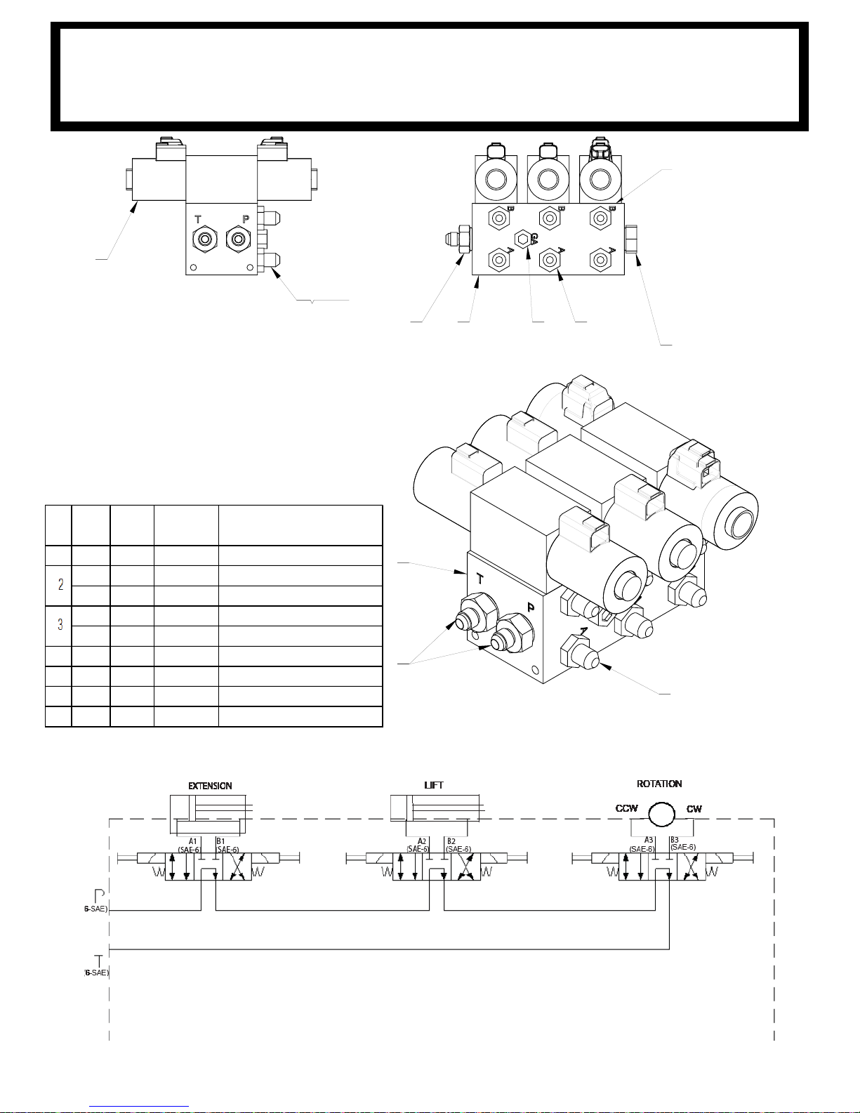
5 TYP
6
1 76
SEAL KIT P/N
320989424
5
66
5
1
ITEM
NO.
HYTOS
QTY
PARKER
QTY.
PART NUMBER DESCRIPTION
1 1 1 320989421 MANIFOLD BLOCK, DO3
3 - 320989428 VALVE, DO3 STACK TYPE, HYTOS
- 3 320989422 VALVE, DO3 STACK TYPE, PARKER
6
- 320989429 COIL, 12V-2.7A HYTOS, FOR 320989420
-
6
320989423 COIL, 12V-2.5A PARKER, FOR 320989420
4 2 2 330072000 PLUG, #10 SAE
5 6 6 202756000 FITTING 6-8 STRAIGHT
6 2 2 202755000 FITTING, -10 SAE/-6 JIC, STR
7 1 1
751034000 PLUG, -6ORB
REPLACEMENT COILS:
(BLACK) = 320989423
(STEEL) = 320989429
4
3203PR/PRX HYDRAULIC CONTROL VALVE
P/N
: 320989420
70
Page 79
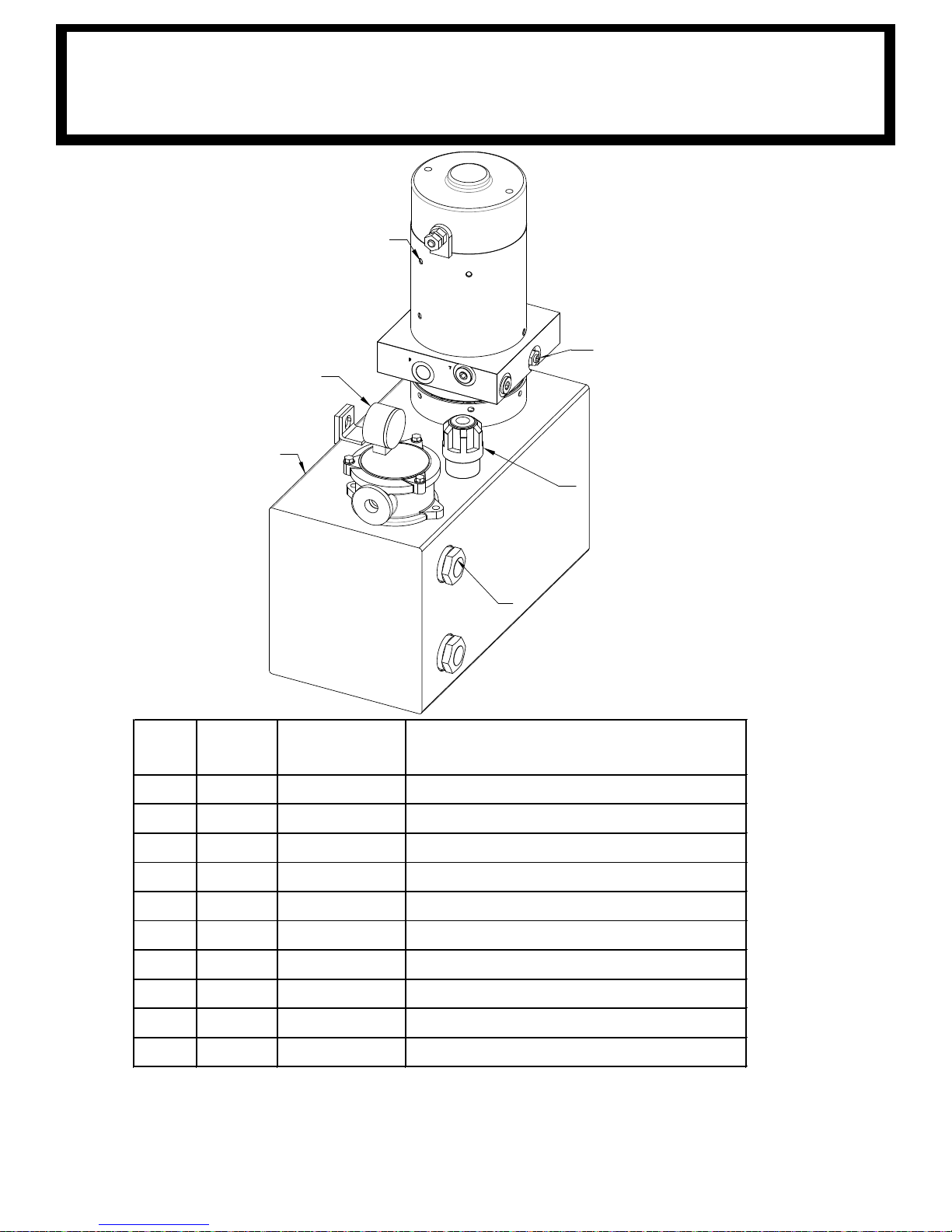
3203 POWER UNIT
5
4
6
3
1
2
ITEM
NO. QTY
PART
NUMBER DESCRIPTION
1 1 320991272 TANK, NEXSTAR 3203/4004EH
2 1 320991908 GAUGE, FILTER USED W/320991270
3 2 320991274 GLASS, SIGHT USED W/320991270
4 1 320991284 BASE ASSEMBLY USED W/320991270
5 1 320991271 MOTOR, NEXSTAR 3203/4004EH
6 1 320991275 CAP,FILLER USED W/ 320991270
7* 1 320991277 VALVE, RELIEF USED W/320991270
8* 1 320991910 FILTER, ELEMENT SMALL EH NEXSTAR
9* 1 320991285 O-RING USED W/ 320991270
10* 1 3209912
86 PUMP, 3203/4004EH
* NOT SHOWN
P/N
320991279
71
Page 80

3203PR GENERAL ASSEMBLY
2
6
14
18
3
12
1
15
17
4
7
16
8
13
9
19
5
APPLY LOCTITE 242 OR 243
TO THREADS OF BOLTS
FM
- P/N: 320989005
72
Page 81
ITEM
NO.
QTY
PART
NUMBER
DESCRIPTION
1 1 320988204 PEDESTAL ASSEMBLY, 3203 PR
2 1 320988103 BOOM ASSY 3203 PR
3 1 320824000 PIN, LIFT CYLINDER
4 1 404220000 PIN WDMT BOOM/PED
5 2 360678000 PIN, 3/16 COTTERLESS RING
6 1 320338002 CABLE ASS'Y, 7/32" x 62FT, THIMBLE END
7 1 361102001 MOUNTING BRACKET, OMNEX PENDANT PLUG
8 1 460158000 RECEIVER, NON-PROPORTIONAL,
9 1 680180000 HARNESS, FM, 3203PR(X)
10* 1 320988013 SHIP KIT, 3203 PR/PRX, FM
11* 1 320988004 DECAL LAYOUT, 3203
12 1 23
9300000 ZERK, GREASE
13 2 005604000 SCREW HX HD 1/4-20UNC X 1 LG
14 1 330371000 SCREW HX HD 3/8-16UNC X 1 LG GR8
15 1 366159000 SCREW HX HD 3/8-16UNC X 1 1/2 LG GR8
16 2 020200000 WASHER SP LK 1/4
17 2 021200000 WASHER FL 3/8
18 2 021100000 WASHER SP LK 3/8
19 1 330372000 NUT HX 3/8-16UNC
* NOT SHOWN
3203PR GENERAL ASSEMBLY
FM
- P/N: 320989005
73
Page 82

3203PRX GENERAL ASSEMBLY
19
5
1789
13
7
1
3
16
14
18
5
4
15
12
6
2
1
APPLY LOCK-TITE
242 OR 243 T
O
BOLT
THREAD
FM
- P/N: 320989004
74
Page 83
ITEM NO. QTY PART NO. DESCRIPTION
1 1 320988203 PEDESTAL ASSEMBLY, 3203 PRX
2 1 320988102 BOOM ASSY 3203 PRX
3 1 404220000 PIN WDMT BOOM/PED
4 1 320824000 PIN, LIFT CYLINDER
5 2 360678000 PIN, 3/16 COTTERLESS RING
6 1 320338002
CABLE ASS'Y, 7/32" x 62FT, THIMBLE END
7 1 680180000 HARNESS, FM, 3203PR(X)
8 1 361102001
MOUNTING BRACKET, OMNEX PENDANT PLUG
9 1 460158000 RECEIVER, NON-PROPORTIONAL,
10* 1 320988004 DECAL LAYOUT, 3203
11* 1 320988013 SHIP KIT, 3203 PR/PRX, FM
12 1 000239300 ZERK, GREASE
13 2 005604000 SCREW HX HD 1/4-20UNC X 1 LG
14 1 366159000 SCREW HX HD 3/8-16UNC X 1 1/2 LG
15 1 330371000 SCREW HX HD 3/8-16UNC X 1 LG
16 2 021100000 WASHER SP LK 3/8
17 2 020200000 WASHER SP LK 1/4
18 2 021200000 WASHER FL 3/8
19 1 330372000 NUT HX 3/8-16UNC
*NOT SHOWN
3203PRX GENERAL ASSEMBLY
FM
- P/N: 320989004
75
Page 84

12
4
5
6
7
8
3
6
7
PLUG REG FROM
320990310 INTO COIL
19
2
TRAVELING BLOCK IS
SHOWN FOR REFERENCE
AND IS LOCATED IN THE
SHIP KIT
APPLY LOCK-TITE
242 OR 243 TO
BOLT THREAD
14
15
9
10
11
13
13
3203PRFX GENERAL ASSEMBLY
FM
- P/N: 320990000
76
Page 85
ITEM
NO.
QTY
PART
NUMBER
DESCRIPTION
1 1 320990200 PEDESTAL ASSEMBLY, 3203 PRFX
2 1 320990100 BOOM ASSY 3203PRFX
3 1 404220000 PIN WDMT BOOM/PED
4 1 320824000 PIN, LIFT CYLINDER
5 1 239300000 ZERK, GREASE
6 2 021200000 WASHER FL 3/8
7 2 021100000 WASHER SP LK 3/8
8 1 330371000 SCREW HX HD 3/8-16UNC X 1 LG GR8
9 1 460158000 RECEIVER, NON-PROPORTIONAL,
10 2 020200000 WASHER SP LK 1/4
11 2 005604000 SCREW HX HD 1/4-20UNC X 1 LG
12 1 330372000 NUT HX 3/8-16UNC
13 2 360678000 PIN, 3/16 COTTERLESS RING
14 1 680180000 HARNESS, FM, 3203PR(X)
15 1 361102001 MOUNTING BRACKET, OMNEX PENDANT PLUG
16 1 320988013 SHIP KIT, 3203 PR/PRX, FM
17 1 320988004 DECAL LAYOUT, 3203
18 1 366159000 SCREW HX HD 3/8-16UNC X 1 1/2 LG GR8
19 1 320338002 CABLE ASS'Y, 7/32" x 62FT, THIMBLE END
3203PRFX GENERAL ASSEMBLY
FM
- P/N: 320990000
77
Page 86
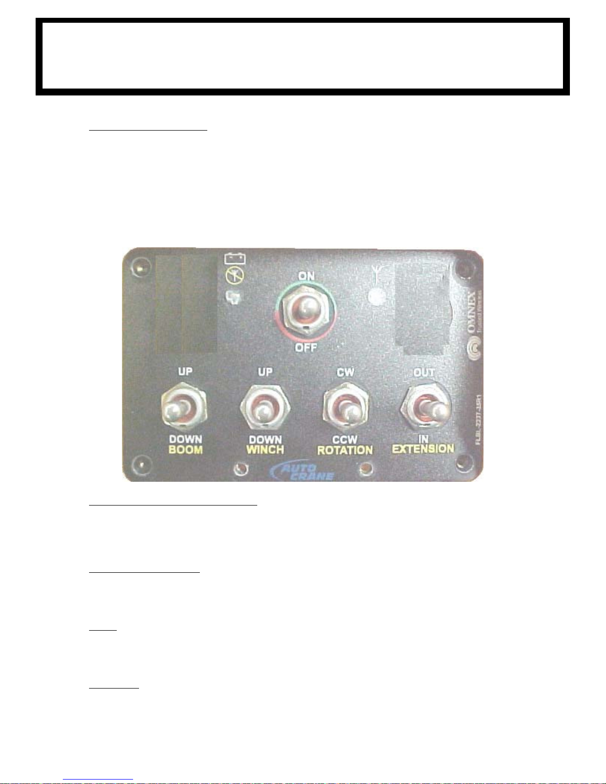
FM CONTROL
US
E AND CARE
TRANSMITTER LAYOUT
nd a y
There is a red light to the left of the ON/OFF Toggle switch a
battery runs down, the red light will begin to flash as well as the yellow light.
If the yellow light is rapidly flashing this indicates that the unit is transmitting. Refer to the Transmitter
Diagnostics Section for a detailed explanation of each light combination.
In addition to the two lights mentioned above there are four function toggle switches. These functions
from left to right are to be used to raise and lower the boom, raise and lower the hoist
cable, rotate the crane and extend and retract the boom.
ellow light to the right. As the
POWER O
The transmitter is powered by 4-AA alkaline batteries, located under the back cover of the housing.
urn the transmitter on, press and hold the Power On Toggle, release once the transmit light
To t
starts blinking. To turn the unit off, press and hold the power off toggle, release after the transmit
light stops flashing.
N/OFF TOGGLE SWITCH
FUNCTION SWITCHES
To operate a function, toggle one of the function switches with either the thumb of the hand holding
the unit o
one time.
CARE
KEEP D
inside the transmitter battery or receiver compartment, immediately dry the unit. Remove the case and
let the unit air dry.
WELDING
DISCONNECT THE RADIO RECEIVER BEFORE WELDING on the crane, load, or truck. Failure to
disconnect will result in the destruction of the radio receiver.
r the thumb or fingers of the opposite hand. More than one function can be activated at
RY. Do not clean the transmitter / receiver under high pressure. If water or other liquids get
78
Page 87
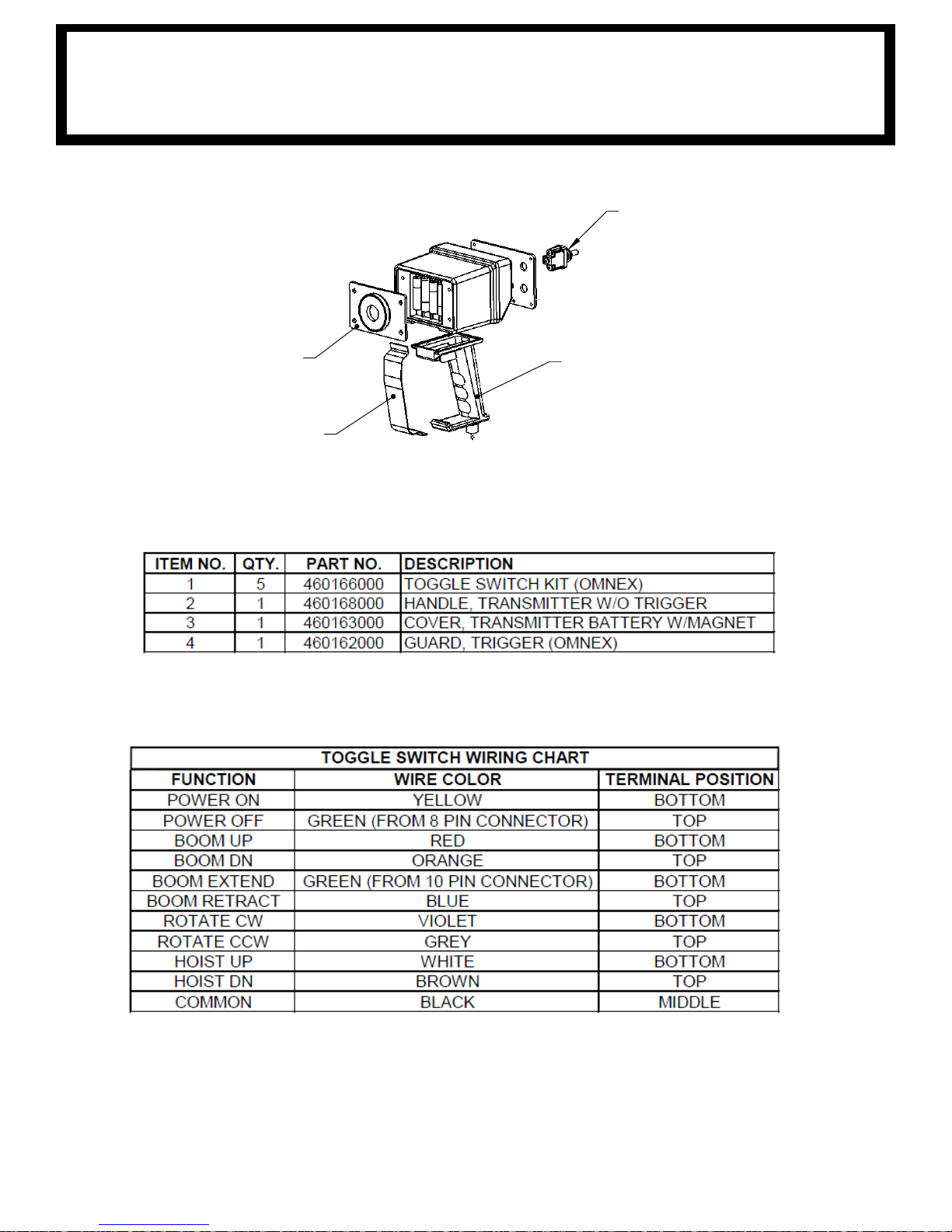
TRA
NSMITTER - P/N: 460157000
FM CONTROL
1
3
4
2
79
Page 88

3203PR/PRX ELECTRICAL SCHEMATIC
ROTATE CW
ROTATE CCW
WINCH UP
WINCH DOWN
BOOM UP
BOOM DOWN
PEND (A)
PEND (B)
1
2
3
4
5
6
7
8
9
10
11
12
B (BLACK PLUG)
(WHT/BLK)
(BLK)
(RED)
PUMP
GROUND
POWER W/LINK
POWER
EXTEND
RETRACT
1
2
3
4
5
6
7
8
9
10
11
12
A (GREY PLUG)
CANNON PLUG
J
L
D
H
M
J
L
D
C
K
F
A
(GRN/BLK)
M
H
E
B
(ORG)
(WHT/RED)
(GRN)
(RED/BLK)
(WHT)
(BLU)
(BRN)
(BLU)
K
F
A
C
E
B
2
4
13 5
(GRY)
(BLK)
PENDANT
PLUG
(ORG/BLK)
(WHT)
P/N
: 680180000
80
Page 89
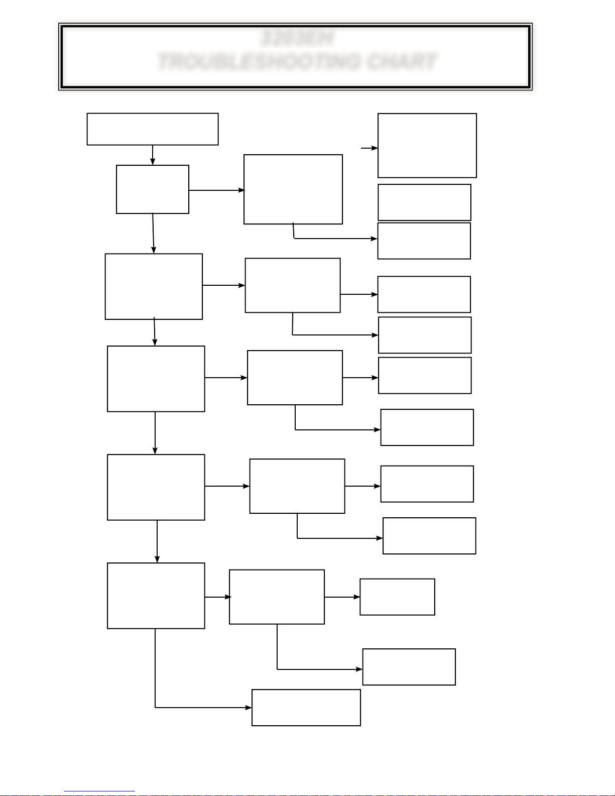
3203EH
TROUBLESHOOTING CHART
CRANE DOES NOT OPERATE
CORRECTL
THIS
CRANE
DOES THE
CRANE OPERATE
UNEXPECT
A FUNCTION IS
NOT SELECTED?
DOES THE
CRANE NOT MOVE
WHEN
IS SELECTED?
Y
IS
A
FM
NO
ADLY WHEN
NO
A FUNCTION
YES
YES
YES
DOES THE LED
LIGHTS SHOW NOR-
OPERA
MAL
WHEN YOU UNPLUG THE
CORRESPONDING COIL?
WHEN YOU MANAULLY
TION ON
RECEIVER
(REF PAGE 83)
DOES IT
MOVING
STOP
DOES IT
T MOVING
STAR
OVERRIDE?
REF. PAGE 88
NO
NO
YES
YES
LIGHTS SHOW NORMAL
GO TO TRANSMITTER
TROUBLE SHOOTING SECTION—P
GO TO RECEIVER TROUBLE
SHOOTING SECTION—
PAGE
GO TO ELECTRICAL
TROUBLE SHOOTING
SECTION— PAGE 82
GO TO HYDRAULIC
TROUBLE SHOOTING
SECTION— PAGE 89
YES
GO TO ELECTRICAL
TROUBLE SHOOTING
SECTION— PAGE 82
DOES THE LED
OPERA
TION ON
TRANSMITTER
(REF PAGE 83)
AGE 86
83
YES
NO
NO
DOES THE
CRANE MOVE SLOW OR
ERRATIC
A FUNCTION
WHEN
IS SELECTED?
NO
IS THERE
EXCESSIVE AMP
OR WIRES HEATING UP?
DRAW
NO
YES
YES
SOUND LIKE THE POWER
UNIT
NO
DOES IT
T MOVING
STAR
NORMALLY WHEN YOU
MANAULLY OVERRIDE?
REF. PAGE 88
NO
DOES IT
IS GOING OVER
RELIEF
CONTACT AN AUTOCRANE
REPRESENTATIVE FOR MORE
DETAILED TROUBLE-SHOOTING
YES
NO
GO TO HYDRAULIC
TROUBLE SHOOTING
SECTION— PAGE 89
YES
GO TO ELECTRICAL
TROUBLE SHOOTING
SECTION— PAGE 82
GO TO HYDRAULIC
TROUBLE SHOOTING
SECTION— PAGE 89
GO TO HYDRAULIC
TROUBLE SHOOTING
SECTION— PAGE 89
GO TO ELECTRICAL
TROUBLE SHOOTING
SECTION— PAGE 82
81
Page 90
3203EH
ELECTRICAL TROUBLESHOOTING CHAR
PROBLEM POSSIBLE CAUSE DIAGNOSIS SOLUTION
CRANE OPERA
UNEXPECT
NO FUNCTION
OPERATES ON THE
CRANE.
TES
ADLY
DAMAGED TOGGLE SWITCH TURN OFF OR UNPLUG PENDANT. SEE
SHORT IN HARNESS UNEXPECTED MOVEMENT WOULD
HOIST FUNCTION ALWAYS
RUNNING (HOIST UP OR
DOWN)
POWER UNIT ALWAYS
ACTIVE
PENDANT TURNED OFF VERIFY TOGGLE SWITCH ON PENDANT
TRANSMITTER/ RECEVIER
NOT SYNCHRONIZED (FM
UNITS ONLY)
CRANE TURNED OFF CHECK MAIN DISCONNECT SWITCH
IF MOVEMENT STOPS
ONLY OCCUR WHEN MULTI-FUNCTIONING FOR HYDRAULIC FUNCTIONS.
UNPLUG COIL TO SEE IF MOVEMENT
STOPS. CHECK FOR VOLTAGE AT THE
COIL CONTACTS.
WITHOUT HOIST BEING SELECTED, THE
HOIST FUNCTION IS OPERATIONAL
IF NO FUNCTION IS SELECTED BUT THE
POWR UNIT IN RUNNING ON WHEN NO
FUNCTION IS SELECTED
IS IN THE “ON POSITION” - HW UNITS
VERIFY YELLOW LIGHT IS FLASHING—
FM UNITS
CHECK LED LIGHTS WITH TRANSMITTER TURNED ON. LINK LIGHT & STATUS
LIGHT SHOULD BE GREEN
LOCATED IN CRANE BOX AND VERIFY IT
IS IN THE ON POSITION.
VERIFY THAT NOTHING WAS ACTIVATING TOGGLE
SWITCH AT TIME OF MOVEMENT. IF NOT ACTIVATED THEN REPLACE SWITCH
TRACE WIRE BACK TO 1/4 TURN BAYONET PLUG.
VERIFY NO DAMAGE TO THE WIRE. CHECK CONNECTORS, THEY SHOULD BE CLEAR OF DEBRIS
AND WATER.
CHECK HOIST RELAY
CHECK WIRING FOR A SHORT
CHECK POWER UNIT RELAY
CHECK WIRING FOR SHORT GOING TO POWER
UNIT
TURN ON TRANSMITTER BY TOGGLING THE
POWER SWITCH INTO THE “ON” POSITION.
SYNCHRONIZE TRANSMITTER—REFERENCE ID
CODE PROGRAMMING SECTION IN MANUAL
TURN SWITCH INTO THE “ON” POSITION
T
THE FOLLOWING FUNCTIONS ARE
INOPERABLE
BOOM DOWN, EXTEND,
HOIST UP
CRANE ROTATES
SLOWLY
LOW TRANSMITTER BATTERY
(FM UNITS ONLY)
LOST GROUND USING A VOLTMETER CHECK MAIN
LOW TRUCK BATTERY
VOLTAGE
POWER UNIT NOT ACTIVATING
ANTI-2 BLOCK CHECK CONTINUITY AT A2B PLUG IN
CRANE OVERLOAD CHECK CONTINUITY AT THE PRESSURE
ADEQUATE OPERATING
CLEARANCES BETWEEN
WORM GEAR AND WORM
WHILE THE TRANSMITTER IS TURNED
ON, CHECK THE YELLOW LED ON
TRANSMITTER SHOULD BE FLASHING SLOWLY. RED FLASHING IS LOW
BATTERY
POWER WIRE AT RELAY PANEL USING
GROUND ON CRANE. THEN CHECK TO
SEE IF SAME VOLTAGE FROM CHASSIS
GROUND & RELAY PANEL POWER.
WHEN RUNNING A FUNCTION, CHECK
VOLTAGE AT HOIST OR HYDRAULIC
POWER UNIT. SHOULD NOT DROP
BELOW 10V.
IF RECEIVER HAS POWER BUT THE
POWR UNIT DOESN’T TURN ON WHEN A
FUNCTION IS SELECTED
THE PEDESTAL WHEN DISCONNECTED
ON THE CORD REEL SIDE. SHOULD BE
A CLOSED CIRCUIT
SWITCH WHEN DISCONNECTED ON THE
PRESSURE SWITCH SIDE. SHOULD BE
A CLOSED CIRCUIT
ROTATION WILL SLOW AT A PARTICULAR
POINT ON THE WORM GEAR
REPLACE TRANSMITTER BATTERIES. IT REQUIRES
(4) AA BATTERIES
USING OHMMETER CHECK RESISTANCE ACROSS
ALL COMPONENTS IN THE GROUND CIRCUIT. PAY
SPECIAL ATTENTION TO GROUND CONTACTING
WORM GEAR. REPLACE OR REMOVE IMPEDENCE
FROM CIRCUIT.
VERIFY TRUCK IS RUNNING WHILE OPERATING
CRANE
CHECK VEHICLE BATTERY FLUID LEVEL
CHECK FOR ADEQUATE WIRE SIZING FOR LENGTH
AND AMPERAGE REQUIREMENTS
CHECK POWER UNIT RELAY
CHECK GROUNDING WIRE FROM RELAY TO PUMP
CHECK MAIN GROUNDING WIRE FROM PUMP TO
GROUNDING BOLT ON PEDESTAL
VERIFY THAT THE TRAVELING BLOCK IS NOT IN
CONTACT WITH BAIL. IF SO, HOIST DN AND CHECK
FUNCTIONS AGAIN. INSPECT END OF BOOM TO
VERIFY BAIL IS IN CONTACT WITH ANTI-2 BLOCK
SWITCH. CHECK BAIL SPRING. CHECK CORD REEL
& WIRE ON SIDE OF CRANE FOR DAMAGE.
VERIFY LOAD ON CRANE DOES NOT EXCEED MOMENT RATING. REFERENCE LOAD CHART.
CHECK PRESSURE ON CYLINDER IN GAUGE
PORT—BOOM MUST BE SUPPORTED BEFORE
REMOVING GAUGE PORT PLUG. VERIFY SWITCH
IS PLUGGED INTO HARNESS.
SLIGHTLY LOOSEN BOLTS ATTACHING TAPERED
BEARINGS TO PEDESTAL. TAP THE BEARING
HOUSING USING A HAMMER AWAY FROM THE
WORM GEAR. RETIGHTEN BOLTS.
ALL FUNCTIONS
OPERATE SLOWLY
LOW TRUCK BATTERY
VOLTAGE
WHEN RUNNING A FUNCTION, CHECK
VOLTAGE AT HOIST OR HYDRAULIC
POWER UNIT. SHOULD NOT DROP
BELOW 10V.
82
VERIFY TRUCK IS RUNNING WHILE OPERATING
CRANE
CHECK VEHICLE BATTERY FLUID LEVEL
CHECK FOR ADEQUATE WIRE SIZING FOR LENGTH
AND AMPERAGE REQUIREMENTS
Page 91

FM CONTROL
Light Legend
Solid
Slow
Flash
Fast
Flash
Red
Light
Green
Light
Alternating Red
& Green Light
Yellow
Light
Tether connection detected
Low battery. Unit will run approximately 10 hours after Battery light starts flashing.
Flashing rapidly for 10 seconds indicates a transmitter failure.
Normal Operation
The Active light will flash several times per second, indicating that the transmitter is sending
signals to the receiver. The Active light will remain on momentarily whenever a function
changes
Normal Operation
The transmitter is in Download Mode.
Stuck switch detected. Ensure that all switches are in a centered position. The transmitter
will not power up when a function is ON.
On Power Down
Unit is still powered. Check for stuck switches, as the transmitter will not power down when a
function is ON. Alternating flash means that the transmitter is in Calibration Mode.
TRA
NSMITTER TROUBLESHOOTING
83
Page 92

Light Legend
Solid
Slow
Flash
Fast
Flash
Red
Light
Green
Light
Alternating Red
& Green Light
Yellow
Light
Normal Operation
Transmitter is OFF
If the transmitter is off, the receiver is operating properly.
Transmitter is ON
When the transmitter is turned on, the Link light (fast flashing) and E-Stop (GREEN) indicates the receiver is
operating properly
Transmitter is in Operation
When a function is activated on the transmitter, the Fault light will turn on GREEN. This indicates the
receiver is operating properly
Transmitter is OFF
When a latched function is activated then the transmitter is turned off, the Fault light will stay on GREEN. If the
system was intentionally designed this way, the receiver is operating properly, if not call for service.
ESTOP
FAULT LINK
STATUS
ESTOP
FAULT LINK
STATUS
Indicator Lights Description Solution
Transmitter is ON
The reason is the transmitter is not
communicating with the receiver.
Refer to Trouble Shooting Chart #3 for solutions
Transmitter is ON
A low battery condition has been detected.
To detect intermittent conditions caused by poor or corroded
ground or power circuits, the GREEN light will continue to flash for
30 seconds after the condition has been removed.
Transmitter is ON
An internal fault with the E-Stop has
been detected.
Check fuse, if OK then: Inspect E-Stop wiring for short circuit. Disconnect E-Stop wire as close to the receiver output as possible. If the
Status light changes to:
t GREEN, a short occurs after disconnection point.
t Stays flashing RED, send it in for service .
Transmitter is ON
A short to ground or excessive current
draw on an output. It is most likely
caused by a wiring fault.
Ensure transmitter is functioning properly, check status of each output
connection: Press each function button and observe Fault Light.
t If GREEN, everything is OK.
t If RED, there is a short in that connection.
Transmitter is ON
E-Stop output is connected with one of
the other outputs or one of the outputs is
shorted to power
Turn off transmitter, if condition clears follow E-Stop wire and
check for connections with other wires. If condition remains one of
the outputs is shorted to power. Test all outputs wires for power.
Transmitter is OFF
A wiring short to the battery has been
detected.
Refer to Trouble Shooting Chart #1 for solutions
Transmitter is OFF
The receiver has detected an internal
fault.
Refer to Trouble Shooting Chart #1 for solutions
Transmitter is ON
Blown fuse detected. (not functional with
proportional units)
Refer to Page 8 for instructions on how to open the receiver case to
access fuse. Check wiring for shorts or bare spots. If fuses continue to blow, call for service.
A setup failure has occurred.
Either hold the Setup button for 5 seconds to return to Setup mode or
cycle power to return to the normal operating mode.
Transmitter is OFF
The receiver is powered incorrectly.
Most likely cause of this condition is that an output wire or the E-Stop
wire has been connected to a power source while the power wire is
disconnected from the Power Input (A6). I.E. Receiver is being powered from an output and not Power Input.
Trouble Indicators
Note: In some cases, the indicator lights will be different depending on whether the transmitter is on or off. Please note the transmitter status in the
“Description” column for each case.
ESTOP
FAULT LINK
STATUS
ESTOP
FAULT LINK
STATUS
ESTOP
FAULT LINK
STATUS
ESTOP
FAULT LINK
STATUS
ESTOP
FAULT LINK
STATUS
ESTOP
FAULT LINK
STATUS
ESTOP
FAULT LINK
STATUS
ESTOP
FAULT LINK
STATUS
ESTOP
FAULT LINK
STATUS
ESTOP
FAULT LINK
STATUS
ESTOP
FAULT LINK
STATUS
ESTOP
FAULT LINK
STATUS
FM CONTROL
RE
CEIVER TROUBLESHOOTING
84
Page 93

Start
Initial Condition:
Turn transmitter off (all lights are off—press
[POWER] OFF)
Cycle power to receiver (turn off and back on)
What is the state
of the lights on
the receiver?
OK state:
Status—GREEN
Link—RED
Fault—OFF
E-Stop—RED
Note: If there is a short to ground on
an output, it is not indicated at this
stage. To test for short to ground,
refer to the “*Fault Light is RED*”
procedure at the bottom of this page
and follow the instructions.
Problem state:
Status—RED
Go to Chart 2
What is the
state of the E-
Stop light ?
OK state:
E-Stop—RED
Problem state:
E-Stop— Flashing
RED
Is the Status
light flashing
RED?
Fuse is blown, change fuse
1. Inspect wiring looking for short circuits (e.g. bare wires)
2. If problem re-occurs, call for service.
YES
NO
Inspect E-Stop wiring looking for short circuits (e.g. bare
wires)
Disconnect the E-Stop output as close to the
receiver output as possible.
If the Status light changes to:
t GREEN, there is a short is the wiring after the discon-
nection point.
t Stays flashing RED, call for service .
What is the
state of the
Fault light ?
Fault Light is
OFF
Fault Light is
Flashing RED
*Fault Light is
RED*
Call for service.
There is a short to supply.
1. Disconnect A & B connectors from receiver and check all
outputs for power (e.g. bare wires, improper connections)
make the correct adjustments
2. Call for service.
There is a short to ground.
Note: This should only occur when the transmitter is on and a
function button is pressed. In this case the Status light will be
GREEN and will turn RED at the same time as the Fault light.
Go to Chart 2 to test the transmitter. If the transmitter is functioning properly, proceed to check the status of each of the output connections:
Press each of the function buttons and observe the Fault Light.
If the light turn GREEN, everything is OK.
If the Light turns RED, there is a short in that connection.
Test the Receiver—R160
Problem state:
Status—flashing
GREEN & RED
The system is wired incorrectly.
Most likely cause is one of the input/output wires has been
connected to the power source.
RE
FM CONTROL
CEIVER TROUBLESHOOTING
85
Page 94
What is the state of
the lights?
Active light is flashing
rapidly and Battery
light flashing slowly
Low Battery—Change Batteries
Note: Low batteries will last approximately 10 hours once the Low Battery
light begins to flash.
Replace batteries by next shift.
Battery light and
Active light flash
alternately.
The transmitter is in Calibration mode
1. Turn unit OFF, then turn back ON
2. If condition persists, call for service.
Test the Transmitter—T150
Turn off the receiver
Ensure there are good batteries in the transmitter
Turn on the transmitter
OK state:
Active light—steady for
about 3 seconds then
goes to fast flash.
Battery light—OFF
Go to Chart 3
Activate a
function
Does the Active
light go to solid
YELLOW?
YES
Either the switch/trigger is
defective or the switch/trigger
connection to the circuit board
is broken.
Call for service
Complete the following steps in order:
1. Check battery orientation
2. Clean battery contacts
3. Check or Replace batteries
4. Call for service
Stuck switch:
1. Return all switches to neutral (OFF)
position
2. Toggle the switch a few times
3. Call for service
No light comes on
at any time
Both the Active light
and the Battery light
flash at the same time
NO
Press and release E-Stop if the condition
persists, then either there is a faulty EStop or transmitter failure—call for service
Battery light flashes
for 10 seconds then
all lights are OFF
FM CONTROL
TRA
NSMITTER TROUBLESHOOTING
86
Page 95
FM CONTROL
Testing the Transmitter / Receiver Communication
What is the status of
the lights of both the
transmitter and
receiver?
Transmitter:
Active light is flashing
Receiver:
Status—GREEN
Link—Flashing GREEN
Fault—OFF
E-Stop—GREEN
Transmitter:
Active light is flashing
Receiver:
Status—GREEN
Link—RED
Fault—OFF
E-Stop—RED
There is no link between the
transmitter and receiver
Do you have a
matched set? (i.e. the
transmitter and re-
ceiver should have
identical ID codes
YES
NO
Was the transmitter
accidentally swapped
with another one on
the job site?
Search the job site for
the correct transmitter.
POSSIBLY
Transmitter and receiver
should be working properly.
The problem may rest with
the machine instead of the
radio system
Call for service
Was it found?
Turn on the transmitter
to check if the units
function correctly. If
not, proceed to Chart 1
NO
YES
The transmitter
code may need to
be re-downloaded
to the receiver
NO
!!Caution!!
Note: Before you proceed with the Download ID procedure located on Page 8, great
care and caution must be adhered to.
If by accident, the transmitters have been switched with another unit, by downloading the
ID code to a new receiver, it is possible for the transmitter to operate 2 units at the same
time (if the original receiver unit is still on the job site). Therefore it must be
certain that the transmitter / receiver pair are the correct set.
Secondly, once the download procedure is completed, ensure all other units on the job
site are stopped. Test the operation of the n
ewly configured set to ensure no other
machines on the site work with the same transmitter.
Once you are certain that the transmitter / receiver pair are a unique set, continue
normal operations.
Call for service.
TR
OUBLESHOOTING CHART 3
87
Page 96
3203EH
PROBLEM POSSIBLE CAUSE DIAGNOSIS SOLUTION
JAMMED CARTRIDGE
TRY TO MANUALLY OVERRIDE VALVE
IF UNABLE TO MOVE STEM.
CARTRIDGE IS JAMMED
REPLACE CARTRIDGE
COUNTER-BALANCE SET
TOO LOW (BOOM-UP &
BOOM-DN )
ADJUST THE COUNTER-BALANCE OUT
TO SEE IF MOVEMENT STOPS.
CONTACT AUTOCRANE FOR PROPER SETTING
OF COUNTER-BALANCE. YOU MAY NEED TO
REPLACE COUNTER-BALANCE.
CONTAMINATE IN CARTRIDGE VALVE STICKS IN CERTAIN POSITIONS
CLEAN CARTRIDGE
NO FUNCTION
OPERATES ON CRANE
HYDRAULIC TANK IS LOW
OR EMPTY
VISUALLY INSPECT THE HYDRAULIC
OIL LEVEL IN THE TANK
FILL TANK TO PROPER LEVEL.
ALL FUNCTIONS
OPERATE SLOWLY
FILTER CLOGGED
CHECK FILTER GAUGE LOCATED ON FILTER
HOUSING
REPLACE FILTER
EXCESSIVE HEAT
DURING OPERATION
OPERATION TIME
CRANE OPERATION IS GENERALLY
DESIGNED FOR INTERMITTENT DUTY
(7 MIN. LOADED / 30 MIN. COOLDOWN)
REDUCE USE OF CRANE TO ALLOW OIL TO
COOL
CRANE MOVES
UNEXPECTEDLY
HYDRAULIC TROUBLESHOOTING CHART
88
Page 97
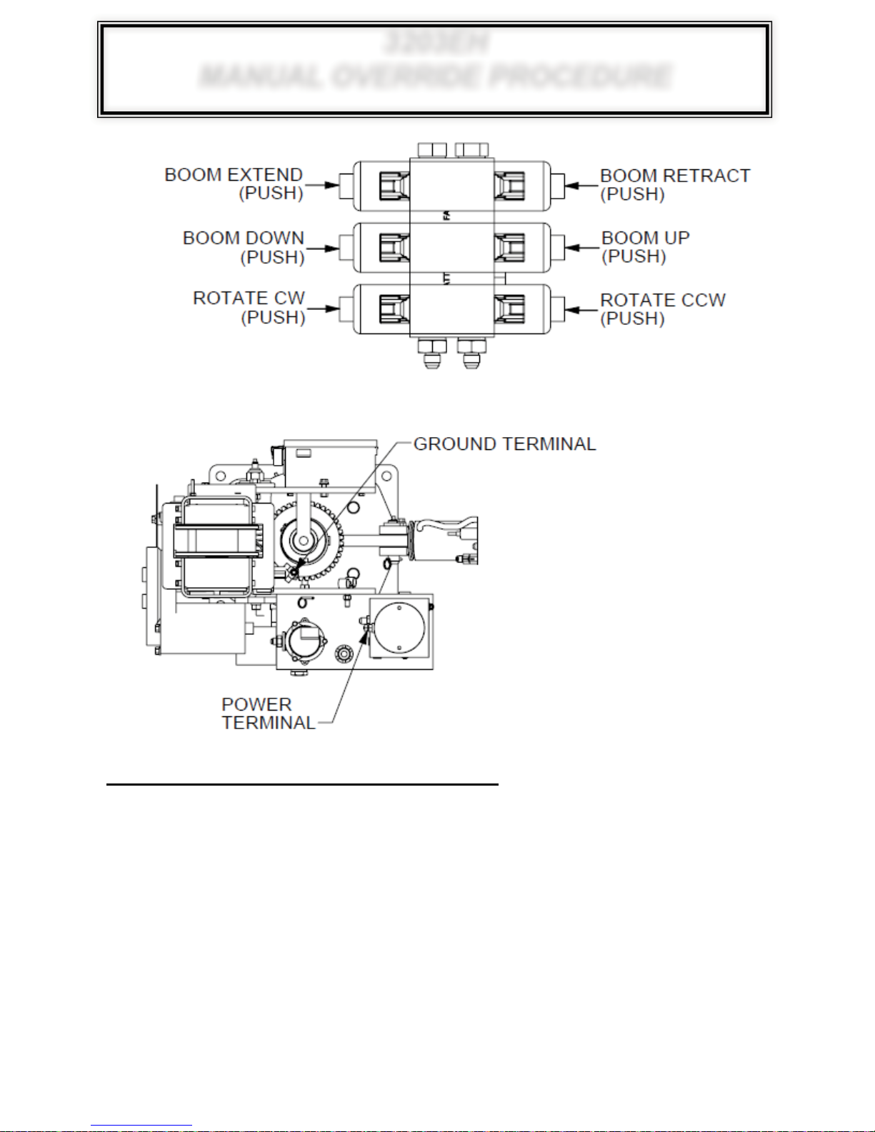
3203EH
MANUAL OVERRIDE PROCEDURE
MANUAL OVERRIDE PROCEDURES
1. APPL
2. APPLY GROUND FROM BATTERY TO GROUNDING CONNECTION
3. SELECT THE FUNCTION DESIRED, THEN PUSH IN OVERRIDE LOCATED ON THE END
CAUTION: MANUALLY OVERRIDING CRANE BYPASSES ALL SAFETY FEATURES. DURING OPERATION MAKE SURE LOAD DOES NOT EXCEED CRANE CAPACITY AND THE
TRAVELING BLOCK DOES NOT COME INTO CONTACT WITH BOOM TIP.
Y 12VDC FROM BATTERY TO PUMP POWER TERMINAL
OF THE COIL USING A PUNCH OR OTHER SMALL OBJECT
89
Page 98
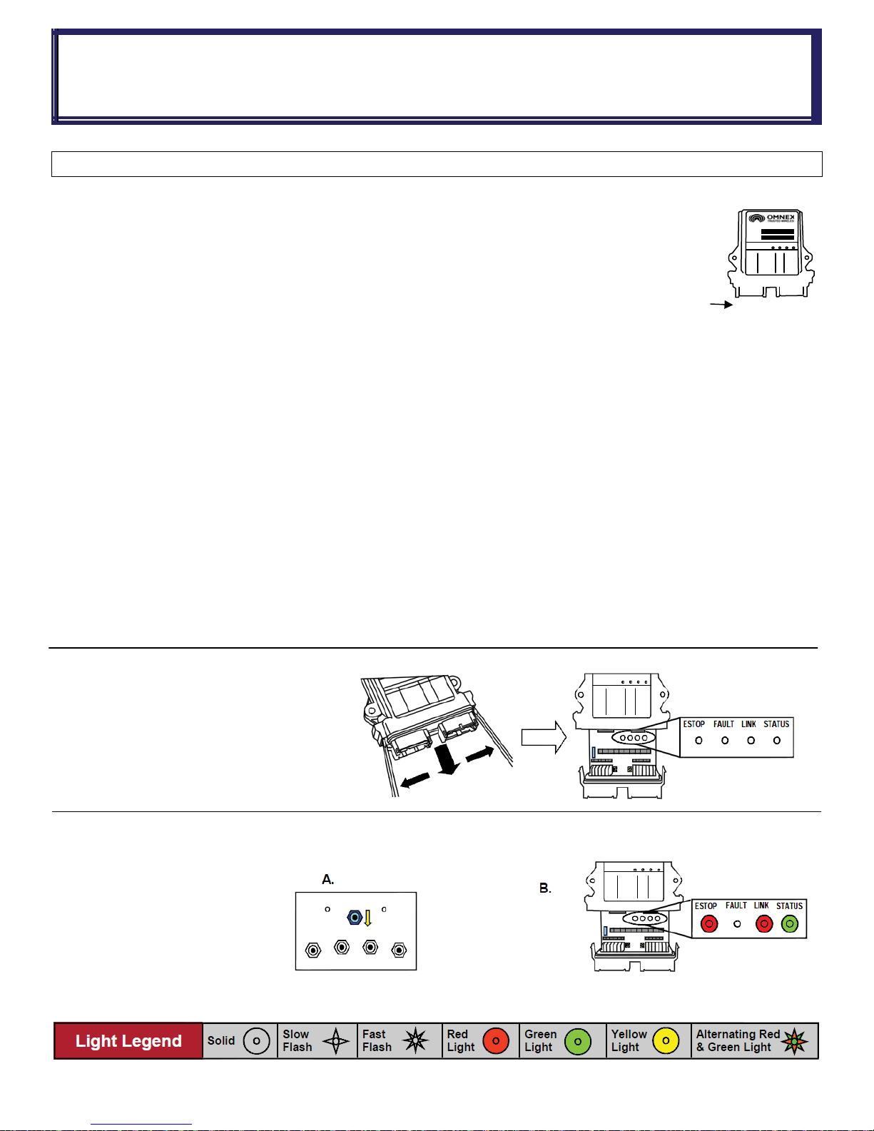
FM CONTROL
ID CODE PROGRAMMING
Download ID Code (
N
ote: Before attempting reprogramming with another transmitter, understand that re-
programming the receiver with another transmitter, could result in two receivers on the job
site responding to the one transmitter. If the original transmitter was sent in for repair,
disconnect the receiver (disconnect connector A) to continue using the machine without
remote capability and without fear of inadvertently operating the machine with the other
transmitter.
Reprogramming Tips:
se a pointy instrument to depress the Setup button on the receiver (i.e. a pen) as the button is relatively small
1. U
2. Follow each step as laid out in the procedure
3. Never lay the receiver circuit board down on anything metallic (there are contact points on the back which could con tact the
metal and damage the receiver)
llow these steps to download the transmitter’s unique ID Code into the receiver. This will allow the receiver to establish
Fo
a radio link with that transmitter.
Refer to the Light Legend below for diagram details.
NOTE: It is necessary to download the ID Code when replacing either the transmitter or the receiver.
NOTE: If the transmitter is connected to the receiver with a Tether Cable, completing only steps 3 and 5 is necessary (it is not
necessary to open the R160 case and press the Setup button).
Use in case of Link Test failure)
!!Caution!!
Connector A
1. Opening the Receiver Case
p is held on by two plastic tabs at
The ca
opposing sides, which can be unlatched as
shown using a screwdriver. Once the cap is free,
the R160 can slide open.
Use a small slotted screwdriver to press the Side
Tabs inward.
2. Prepare Transmitter, Power Receiver
A. Press [POWER] OFF
B. Supply power to the receiver
90
Page 99
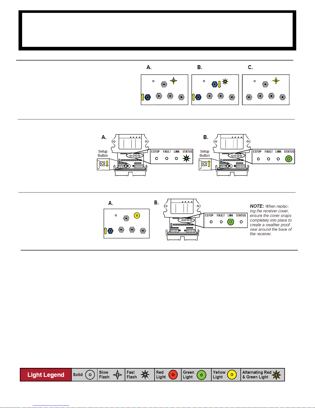
ID CODE PROGRAMMING (CONT.)
FM
3. Power Transmitter into Configuration Mode
A. Press & hold [BOOM] switch in the UP position
B. Press & release [POWER] switch in the OFF
position
C. Release [BOOM] switch
The ACTIVE LED will flash once per second.
4. Put Receiver into Setup
A. Press & hold [Setup] button
until (Status) light goes from
slow flash to fast flash
B. Release [Setup] button.
(Status) light goes to solid
GREEN, (Link) light turns off
CONTROL
NOTE: If left idle in Setup Mode for over 30 seconds, the receiver will time out. The (Link) light and (Status) light will flash RED rap-
idly. To return to Setup Mode, repeat step 4.
Download ID Code
5.
A. Press & release [BOOM]
switch in the UP position
B. The R160 (Link) light goes to
GREEN. Once complete, (Link)
light goes to RED as the transmitter turns off
91
Page 100

NOTE
S
92
 Loading...