

Page 1
QUICK START GUIDE
Thank-you for your purchase!
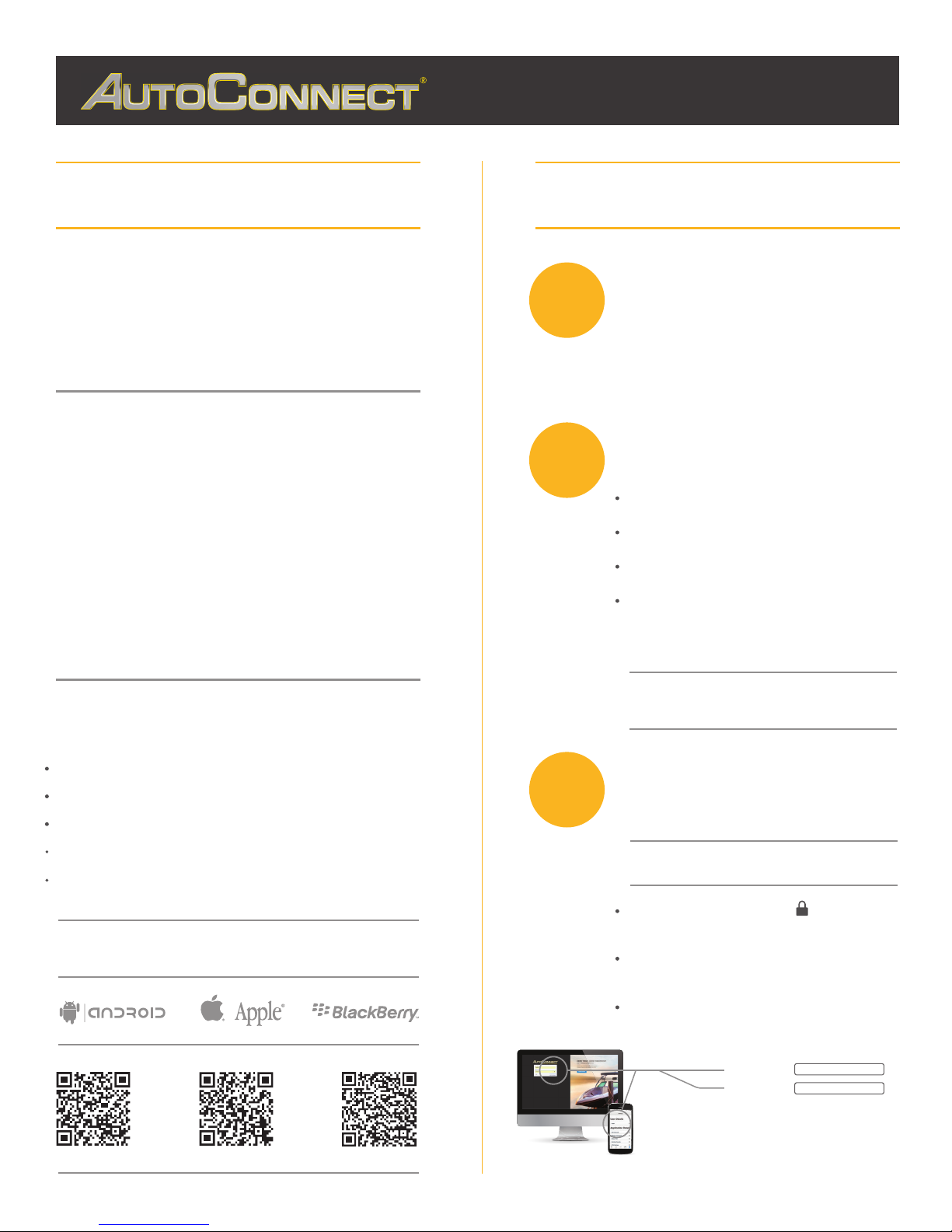
INSTALLER PORTAL
You’ve made the decision to have full control of
your vehicle. Follow the steps below to begin a
new era of vehicle controls.
1.
Ensure you have the Serial # for your device.
Visit our website and click on the “Activate” tab, 2.
3. Select YOUR model number (device type) and
and fully complete forn
Once submitted you will receive a confirmation
email from Northsat Distribution with the details
of your device activation.
autoconnectgps.com1 855 287 4477
TAKE CONTROL OF YOUR VEHICLES LIKE
NEVER BEFORE!
1
2
DETERMINE INSTALLATION TYPE
When installing an Autoconnect device you
must first determine the installation type.
The following pages will help you determine
the type and instructions for installation.
INSTALL YOUR AUTOCONNECT
GPS MODEM
Choose proper installation location ensuring to
follow instructions on install guide
Determine with customer if installation is to be
stealth (not visible)
Have label facing the sky and clear from any
metal above it.
Actual location will vary by vehicle year, make
and model.
TIP
WE RECOMMEND AFFIXING THE SID STICKER
TO THE DOOR JAMB OF THE VEHICLE
Start, Lock, Unlock, open your trunk (*AC200GPS3G Only)
Know the vital statistics of your vehicle(s)
Request a vehicle(s) Location On-Demand
Monitor vehicle(s) for Aggressive Driving and Excessive Idling
Know where your vehicle(s) went, and how they got there
ON ALL THREE MAJOR PLATFORMS
3
TEST THE DEVICE FUNCTIONS
TIP
Choose the proper IC3 Protocol if applicable
before sending any test commands
Click on the Customer Log-in icon at the top
of any page of the autoconnectgps.com website
or download the free App for your mobile device.
Each Device comes with “TEST DATA” for you
to test all functions. This data will expire a few
days after installation.
Use the SID# for USERNAME and PASSWORD.
Username
Password
REV030617
Page 2
QUICK INSTALL GUIDE
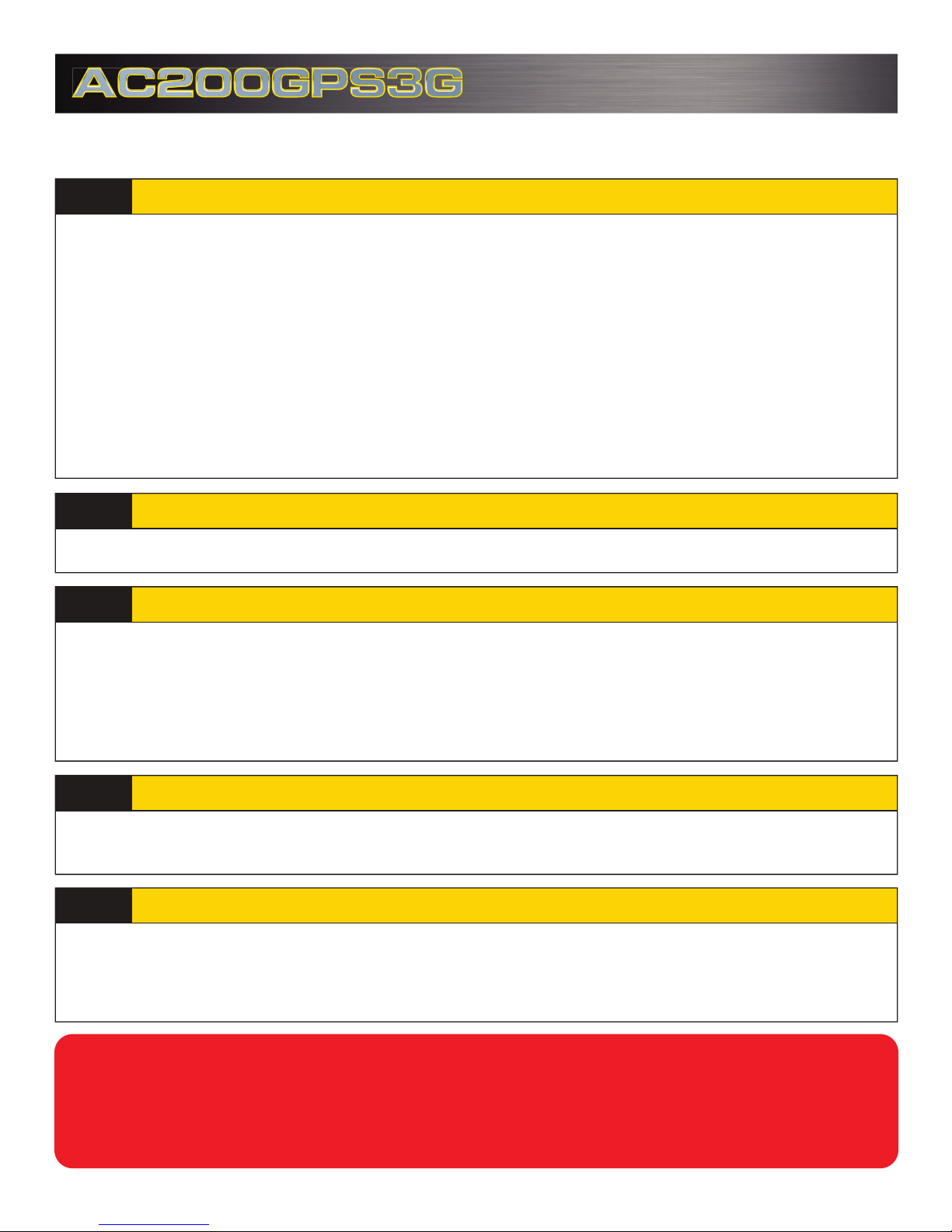
Attention: This modem is shipped temporarily pre-activated for the installer to send
up to 50 test commands before having to send in the activation form.
STEP 1:
Depending upon your requirements, the AC200GPS3G module can be installed in a variety of ways.
Fortin EVO-ALL (Standalone FW)
Fortin EVO-ONE
STEP 2:
Please see the following pages for detailed instructions and wiring diagrams.
STEP 3:
Failure to adhere to these suggestions will result in a weak cellular and/or GPS signal and will affect
the performance of the device.
- Secure in upper portion of dash in a hidden location with correct side pointing
skyward .(label will indicate proper orientation)
- Do not cover with metal or position near any source of interference (Vehicle Radio, BCM). Keep a
safe distance of at least 24”.
Determine Installation Type and Options
Complete the wire connections according to the selected Installation Type.
Position the AC200GPS3G Module in an Optimal Location
STEP 4:
Blue: 2 Flashes / Second Connected / Online
Green: 1 Flash / Second Valid GPS
STEP 5:
Each AC200GPS3G device is shipped pre-activated for the installer to send up to 50 test
commands before having to complete the online activation form. It is HIGHLY recommended that
you follow one of the test procedures below to ensure proper functionality. Alternatively you can
call Certified Tracking Solutions and we will perform the test with you.
Conrm LED Status
Conrm Vehicle Connectivity and GPS location
Call Certified Tracking Solutions at 1-780-391-3800.
For Live Tech Support:
Toll Free 1-855-287-4477(CTS-4GPS)
Monday to Friday 8AM to 5PM MST
AutoConnectGPS.com
REV022 717
Page 3
QUICK INSTALL GUIDE
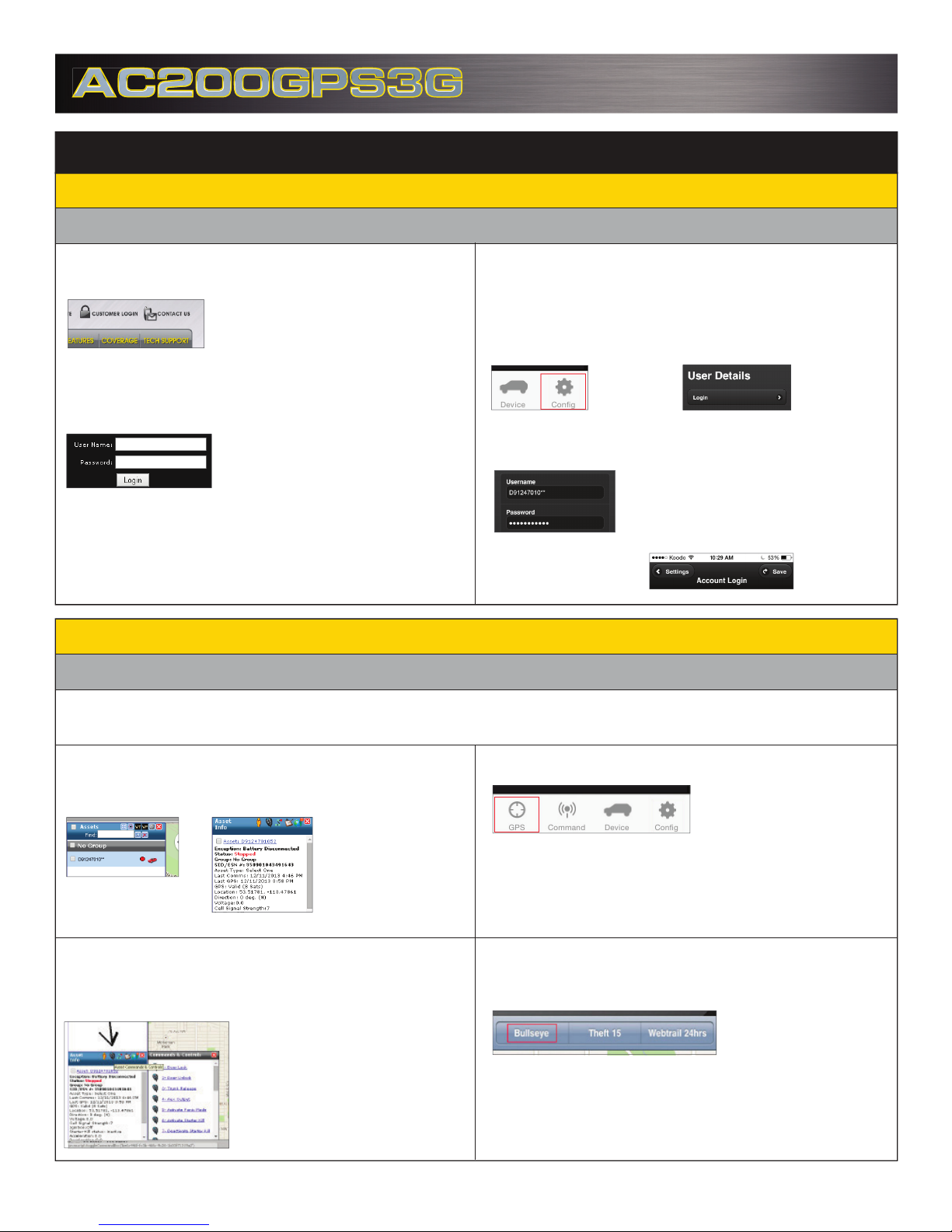
Test procedure
1) Login to view and test the AC200GPS device
A: via the AutoConnect website B: via the AutoConnect Smartphone App
a) Go to www.AutoconnectGPS.com and
click on “ Customer Login”
a) Download the AutoConnect Smartphone app by searching “Autoconnect
GPS” for iPhone, Android or Blackberry
b) Open App and click on “Config ” then
“Login”
b) Enter the AC200GPS3G’s Serial# (ESN)
for both the User Name and password.
c) Click Login.
c) Enter the AC200GPS3G’s Serial# (ESN)
for both the User Name and password.
The AutoConnect website dashboard
should load and display the Serial number
of the AC200GPS3G device that you are
installing.
d) Click “Save”
2) Test Vehicle GPS Connectivity
A: via the AutoConnect website B: via the AutoConnect Smartphone App
The successful completion of this section will enable you to see the current position of the
AC200GPS3G device on the dashboard/Smartphone map.
a) Click on device serial # on the left side
of the screen. The asset info box will open
on the bottom left corner of the screen.
b) Click on the “Asset Commands & Controls” icon located at the top of the Asset
Info box*
*if using Type 2 to Type 9 please ensure you
have selected appropriate data protocol
a) Click on the “GPS” tab
b) Click on the “Bullseye” button at top left
of screen
Page 4
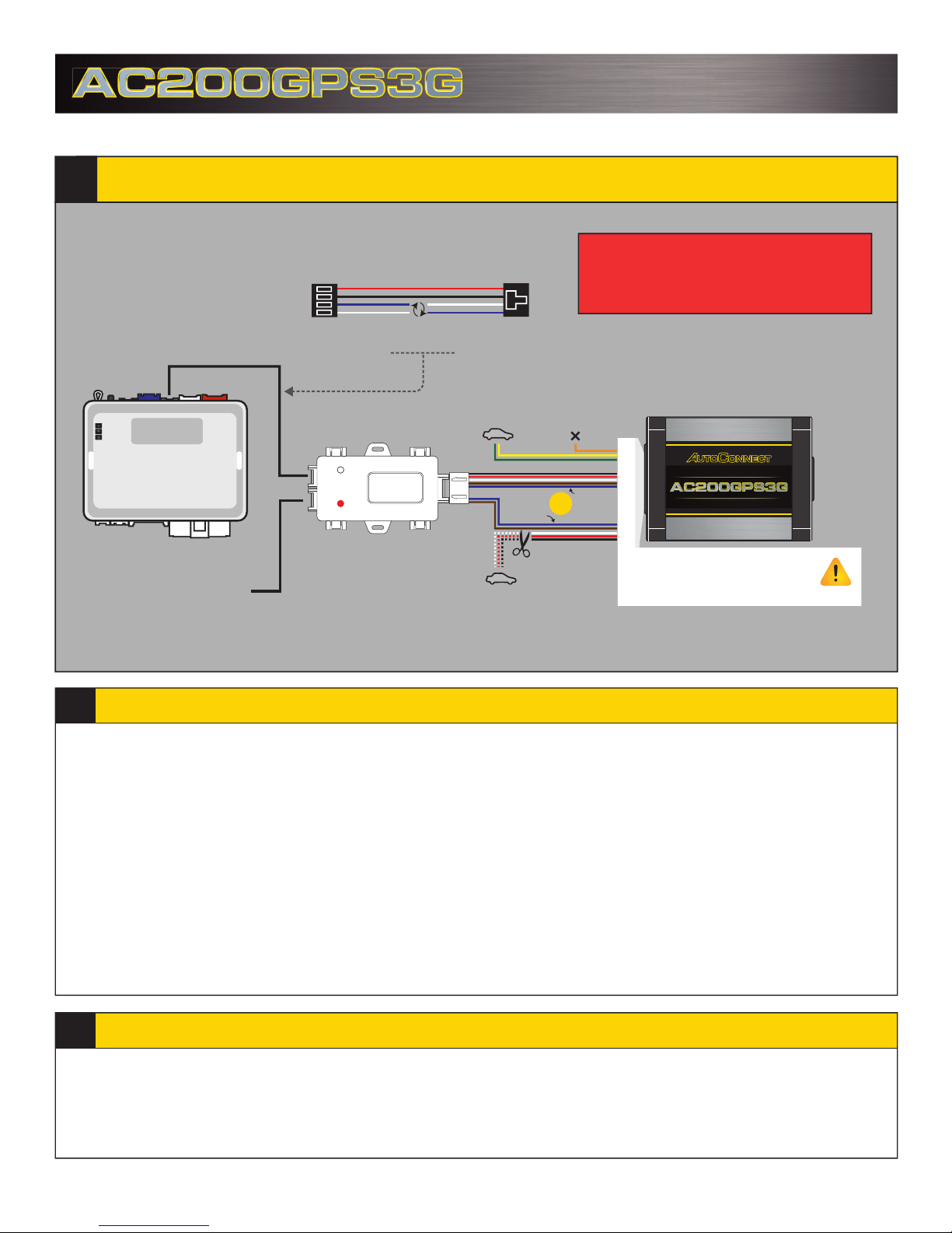
Fortin EVO-ALL (Standalone FW)
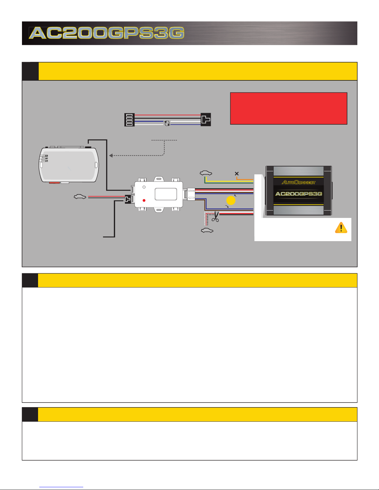
EVO-ALL & AC200GPS3G
RS232
Data Port
Red - 12V+
Black - Ground
*Required if not using
a T-Harness
To Optional Solace RF Kit
REQUIRED DATALINK
CABLE MODIFICATION*
Swap the BLUE & WHITE wires on one end of
the cable or cut and reconnect.
*CABLE TO BE MODIFIED
IC3
Requirements
IC3 Firmware :
IC3 Protocol Ver :
Ver 22 & UP
IC3 Protocol 2 (FoRF)
Option H2 Fortin RFBypass Program :
Optional Connections
Green - Starter Kill (-)
Yellow - Input (-)
Orange - Not Used
THIS SIDE UP TOWARDS SKY
T R A CKING SYST EMS
Option 1
Option 2*
OR
www.AutoConnectGPS.com
Attention:
Applying 12V+ to the Brown
Black - Ground
Red - 12V(+)
White - Ignition
*Hardwiring these connections are optional for True Voltage readings.
or Blue Wire will void warranty
Installation Steps
1. Program EVO-ALL as per Fortin installation instructions for vehicle. (Ensuring to select option H2 in Flashlink Manager) or visit
http://fortin.ca/download/20101/autoconnect_evo-all.pdf
2. Complete installation as per Fortin installation diagram including the programming of the bypass module.
3. Ensure you have swapped the BLUE & WHITE wires on datalink cable between the IC3 and Fortin module.
4. Connect Data link cable from IC3 to RS232 port on EVO-ALL (Ports are interchangeable on IC3). Connect Power and Ground
if not using a T-Harness.
5. For true voltage cut and hardwire the Red, Black, and White directly from the Autoconnect devic
*DO NOT CUT THE DATALINK CABLE
6. Scroll to the bottom of the commands and send the required Installer Protocol.
7. For Fortin EVO-ALL select IC3 Protocol 2 (FoRF)
Program the Autoconnect to Fortin module by performing the following:
8.
-Hold programming button while inserting datalink cable to EVO-ALL. Release button when Blue & Red LED’s Turn on
-Press and hold the programming button on the EVO-ALL (The LED’s will turn o then back on approx 5 seconds),
release button
-Turn Ignition ON (ALL 3 LED’s should be on now)
-Send the Lock command from the Autoconnect. The Blue and Red LED’s should ash once.
-Turn Ignition OFF
9. Mount the Autoconnect module as described in Autoconnect Install.
e to the vehicle.
Programming and Testing
1. Open the Autoconnect App or Dashboard
2. Log in to the Autoconnect device installed using the SID # as both username and password.
3. Go to the command
4. Test all the application functions (Start, Stop, Lock, Unlock, Auxiliaries, ETC. GPS).
5. We reccomend axing the SID Sticker to the door jamb of the vehicle.
tab on the bottom of the app, or the remote funciton of dashboard
Page 5
Fortin EVO-ONE
EVO-ONE & AC200GPS3G
RF PORT
To Optional Solace RF Kit
REQUIRED DATALINK
CABLE MODIFICATION
Swap the BLUE & WHITE wires on one end of
the cable or cut and reconnect
*CABLE TO BE MODIFIED
IC3
Requirements
IC3 Firmware :
IC3 Protocol Ver :
Ver 22 & UP
IC3 Protocol 2 (FoRF)
Option H2 Fortin RFBypass Program :
Optional Connections
Green - Starter Kill (-)
Yellow - Input (-)
Orange - Not Used
THIS SIDE UP TOWARDS SKY
T R A CKING SYST EMS
Option 1
Option 2*
OR
www.AutoConnectGPS.com
Attention:
Applying 12V+ to the Brown
Black - Ground
Red - 12V(+)
White - Ignition
*Hardwiring these connections are optional for True Voltage readings.
or Blue Wire will void warranty
Installation Steps
1. Program EVO-ONE as per Fortin installation instructions for vehicle (Ensuring to select option H2 in Flashlink Manager) or visit
http://fortin.ca/download/26701/autoconnect_evo-one.pdf
2. Complete installation as per Fortin installation diagram.
3. Ensure you have swapped the BLUE & WHITE wires on datalink cable between the IC3 and Fortin module.
4. Connect Data link cable from IC3 to BLUE RF PORT on EVO-ONE (Ports are interchangeable on IC3).
5. For true voltage cut and hardwire the Red, Black, and White directly from the Autoconnect device to the vehicle.
*DO NOT CUT THE DATALINK CABLE
6. Scroll to the bottom of the commands and send the required Installer Protocol.
7. For Fortin EVO-ONE select IC3 Protocol 2 (FoRF)
8. Program the Autoconnect to Fortin module by performing the following:
-Turn Ignition On.
-Press and
-Press and release the brake pedal.
-Send the Lock command from the Autoconnect. The park lights will ash once to conrm.
-Press and release the brake pedal then turn igntion OFF.
9. Mount the Autoconnect module as described in the Autoconnect Install guide Step 3.
hold the Valet switch until LED ashes then release. Then press Valet switch 5x.
Programming and Testing
1. Open the Autoconnect App or Dashboard
2. Log in to the Autoconnect device installed using the SID # as both username and password.
3. Go to the command tab on the bottom of the app, or the remote funciton of dashboard
4. Test all the application functions (Start, Stop, Lock, Unlock, Auxiliaries, ETC.
5. We reccomend axing the SID Sticker to the door jamb of the vehicle.
GPS).
Page 6
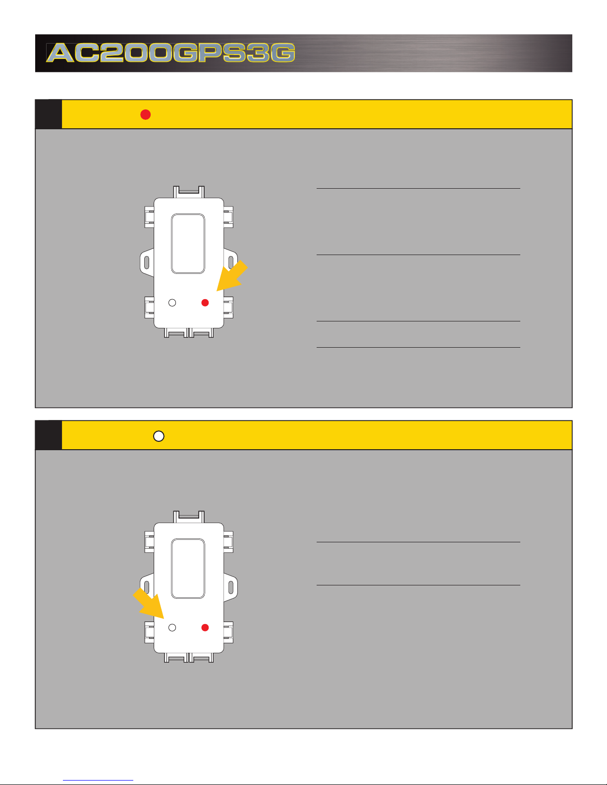
Red LED
LED Diagnostics
FLASHING
Quick ashes
FW Verison Number
eg, 2 quick then 2 quick = Ver 22
IC3IC3
Slow ashes
Data Protocol Version
eg, 5 Flashes = IC3 Data Protocol 5 (SO/TI)
Solid ON = Ignition ON
White LED
Solid OFF = Ignition OFF
FLASHING
1 Flash = AC200 to Device
2 Flashes = Device to AC200
 Loading...